EP0986207A2 - Transmission of a subchannel, using a pilot signal - Google Patents
Transmission of a subchannel, using a pilot signal Download PDFInfo
- Publication number
- EP0986207A2 EP0986207A2 EP99117442A EP99117442A EP0986207A2 EP 0986207 A2 EP0986207 A2 EP 0986207A2 EP 99117442 A EP99117442 A EP 99117442A EP 99117442 A EP99117442 A EP 99117442A EP 0986207 A2 EP0986207 A2 EP 0986207A2
- Authority
- EP
- European Patent Office
- Prior art keywords
- signal
- frequency
- data
- sub
- main
- Prior art date
- Legal status (The legal status is an assumption and is not a legal conclusion. Google has not performed a legal analysis and makes no representation as to the accuracy of the status listed.)
- Withdrawn
Links
Images


Classifications
-
- H—ELECTRICITY
- H04—ELECTRIC COMMUNICATION TECHNIQUE
- H04H—BROADCAST COMMUNICATION
- H04H20/00—Arrangements for broadcast or for distribution combined with broadcast
- H04H20/44—Arrangements characterised by circuits or components specially adapted for broadcast
-
- H—ELECTRICITY
- H04—ELECTRIC COMMUNICATION TECHNIQUE
- H04H—BROADCAST COMMUNICATION
- H04H20/00—Arrangements for broadcast or for distribution combined with broadcast
- H04H20/28—Arrangements for simultaneous broadcast of plural pieces of information
-
- H—ELECTRICITY
- H04—ELECTRIC COMMUNICATION TECHNIQUE
- H04L—TRANSMISSION OF DIGITAL INFORMATION, e.g. TELEGRAPHIC COMMUNICATION
- H04L5/00—Arrangements affording multiple use of the transmission path
- H04L5/02—Channels characterised by the type of signal
- H04L5/06—Channels characterised by the type of signal the signals being represented by different frequencies
Landscapes
- Engineering & Computer Science (AREA)
- Signal Processing (AREA)
- Computer Networks & Wireless Communication (AREA)
- Radio Relay Systems (AREA)
- Digital Transmission Methods That Use Modulated Carrier Waves (AREA)
- Synchronisation In Digital Transmission Systems (AREA)
- Reduction Or Emphasis Of Bandwidth Of Signals (AREA)
Abstract
Description
- The present invention relates to a data transmission system, a communication station and a data transmission method and more particularly, to a communication technology which is suitable when digital signal data is transmitted between communication stations located away from each other in the form of microwave. Data to be transmitted include television signals of digital and analog types and other types of information.
- Explanation will be made below as to a general arrangement of a transmission system for transmitting data with use of high frequencies of about 1 GHz or more.
- A transmission side once performs baseband modulation over input data to obtain a signal subjected to the baseband modulation, and creates a signal Sit having an intermediate frequency from the baseband-modulated signal. And the transmission side eventually creates a signal Sht having a final radio frequency (RF) after subjected to an up-conversion, and transmits the radio-frequency signal Sht.
- A receiver side, on the other hand, converts a radio-frequency signal Shr received and amplified in a similar manner to in the transmission side to a frequency down-conversion to obtain a signal Sir having an intermediate frequency, and then subjects the signal Sir to a baseband demodulation.
- An example of a transmission system having a prior art arrangement is shown in Fig. 7.
- In the transmission side, a
baseband modulator 1 converts main data (to be transmitted) received from aterminal 22 to the signal Sit of the intermediate frequency on the basis of a clock CK2 of a frequency f2 received from an oscillator (OSC) 9B. In the illustrated example, the frequency fit of the signal Sit is related to the frequency f2 of the clock CK2. In other words, an accuracy in the frequency fit of the signal Sit depends on an accuracy in the frequency f2 of the clock CK2. - A
frequency converter 3 converts with respect to frequency the signal Sit of the intermediate frequency fit to the signal Sht of the radio-frequency fht on the basis of a frequency f1 of a clock CK1 received from an oscillator (OSC) 9 as a reference frequency. - A
power amplifier 4 amplifies the signal Sht to such an level that the signal Sht can have a predetermined transmission power, and transmits the power-amplified radio-frequency transmission signal from anantenna 5 toward anantenna 10 on the receiver side. - In the receiver side, a
preamplifier 13 outputs a received signal as the radio-frequency-amplified signal Shr. Afrequency converter 11 down-converts the signal Shr to the signal Sir of an intermediate frequency fir on the basis of a frequency f3 of a clock CK3 received from an oscillator (OSC) 9C as a reference frequency. In the illustrated example, a frequency shift in the oscillator (OSC) 9C is related to a frequency shift in the signal Sir of the intermediate frequency. - A
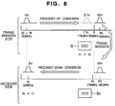
baseband demodulator 12 demodulates the original main data from the signal Sir of the intermediate frequency on the basis of a frequency f4 of a clock CK4 received from oscillator (OSC) 9D as a reference frequency, and then outputs the demodulated data to aterminal 24. - The entire operation of the above system including the frequency conversion will now briefly explained with use of Fig. 8. It is assumed that the intermediate-frequency signal Sit on the transmission side has the frequency fit and the final radio-frequency signal Sht on the transmission side has the frequency fht. It is also assumed that the receive signal Shr on the receiver side has the frequency fhr and the intermediate-frequency signal Sir on the receiver side has the frequency fir.
- In this case, the frequency conversion is carried out by multiplying the clock CK1 corresponding to the frequency difference f1 between the frequency fit and the reference frequency fht of the transmission side by the signal Sit.
- This results in generation of the signal Sht of the frequency fht obtained by adding the frequency fit to the frequency f1 as well as generation of a signal S'ht of a frequency f'ht obtained by subtracting the frequency fit from the frequency f1.
- A specific example of how to obtain an final output frequency of 1.82 GHz will be explained below.
- When fit = 20 MHz and f1 = 1.8 GHz, output signals having frequencies of 1.82 GHz and 1.78 GHz are obtained. In this case, one of the output signals having the frequency of 1.78 GHz is removed by a filter and only the signal of the frequency of 1.82 GHz is used as a transmission signal.
- Such a prior art arrangement as mentioned above has a practical problem that, even when the oscillators (OSC's) 9 and 9C located as separated into the transmission and receiver sides are each of a high-accuracy crystal resonator type, differences in temperature characteristic, etc. between the oscillators causes the oscillation frequencies of the oscillators not to become exactly the same, because the oscillators are asynchronous, thus resulting more or less in a frequency difference.
- As mentioned above, the intermediate-frequency signal Sit is up-converted by the
frequency converter 3 of the transmission side to the radio-frequency signal Sht and is down-converted by thefrequency converter 11 of the receiver side to the intermediate-frequency signal Sir. - At this time, if the frequency f1 of the oscillator (OSC) 9 coincides with the frequency f3 of the oscillator (OSC) 9C, then the frequency fit of the signal Sit of the transmission side coincides with the frequency fir of the signal Sir of the receiver side. However, due to the aforementioned frequency difference, since the signal Sir has such a frequency shift as mentioned above in the
baseband demodulator 12 of the receiver side, the original main data cannot be normally demodulated. - In the case of ground wave digital TV broadcasting using an orthogonal frequency division multiplex (OFDM) system for example, a baseband modulating and demodulating system uses about 6,000 multicarriers having an interval of about 1 KHz. Thus when there exists 1 KHz or more of accuracy lack, in particular, in the frequency conversion of the receiver side, this will involve great influence such as difficult normal demodulation.
- In the case of OFDM wave used in the ground wave digital TV broadcasing, there is a pilot signal interpolation system wherein some of multicarriers are used as frequency references in transmission and receiver sides. A technique for interpolating a pilot signal in an OFDM signal is disclosed in "Development of the OFDM Modem", Kisoda. et al., Technical Report of The Institute of Image Information and Television Engineers, August 26, 1997, pp. 13-18.
- However, the pilot signal interpolation system has its limit in synchronizable range. In particular, when signals of an UHF band are frequency-converted to signals of a microwave band as a transmission band and converted again to signals of the UHF band in the receiver side, the frequency shift becomes great.
- In this case, the accuracy of the oscillator is defined by ppm. For example, even when the oscillators of the transmission and receiver sides have each an accuracy of 1 ppm, a frequency error between the transmission and receiver sides is 7 KHz for a transmission band of 7 GHz and is about 800 Hz for a transmission band of 800 MHz.
- Accordingly when frequency conversion is carried out from the UHF band to the microwave band, an error caused by the up-conversion/down-conversion of at the transmission/receiver side is increased to about 10 times an error of the frequency conversion in UHF band, which causes a great harm in the entire baseband demodulating operation based on the pilot signal interpolation system.
- Further, even when the frequency shift is suppressed to such a level as to cause no influence on the baseband demodulation, the frequency error to be transmitted in broadcasting applications is restricted to an accurate range of several tens of Hz.
- For this reason, an arrangement of provision of accurate and highly expensive oscillators of rubidium or the like in the respective frequency converters in the transmission and receiver sides has had to be employed for the broadcasting applications.
- Further, in addition to the problem of oscillator frequency fluctuations, the data transmission system has a problem that there must be provided a private line for maintenance contact or control signal which is to be used by a radio facility manager, in addition to the main data transmission line.
- More specifically, there are transmission requests which include a digitized voice signal for contact between the transmission and receiver sides and control data for control of devices in the receiver or relay stations. In order to meet such a demand, it is indispensable as a practical matter to secure a special channel for the control data in addition to the main data line.
- For example, portable phones spread in these years, but relay or transmission points of the phones are often positioned out of their speech enable areas, which requires provision of additional radio channel exclusive for maintenance contact and control signals. In reality, however, it is practically impossible to provide such radio channels as contactable with all the relay and transmission points.
- There is also considered a method for inserting contact information in part of the aforementioned main data (such as a vertical blanking period having VITC (Vertical Interval Time Code) or the like embedded therein in an analog system) in the data transmission. In this method, however, when it is desired to make a separate contact from a first relay point to a second relay point, it becomes highly troublesome to exchange detailed contact information.
- More specifically, in order to interchange information inserted in the main data, it is necessary to demodulate the main data up to its baseband, interchange part thereof for other data, and then re-modulate it. This involves generation of a processing delay time. Accordingly it is impossible to interchange the partial data during use of the main data as ordinary broadcasting data.
- It is therefore an object of the present invention to solve the problems in the prior art, enable elimination of a frequency shift even when an inexpensive oscillator is used and normal demodulation of predetermined data, and also enable transmission of other data in addition to the predetermined data.
- In a data transmission system in accordance with the present invention, a transmission side adds to a main signal a sub-signal having a frequency out of a frequency band of the main signal as frequency conversion information and transmits the composite signal including the sub-signal and the main signal, whereas, a receiver side extracts the added sub-signal from the received composite signal to make a frequency conversion reference for demodulation of the main signal coincide with that of the transmission side. At the same time, the transmission side modulates the sub-signal to be added with sub-data and also transmits it, while the receiver side demodulates the sub-data.
-
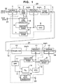
- Fig. 1 is a block diagram of an entire arrangement of an embodiment of a data transmission system in accordance with the present invention;
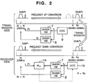
- Fig. 2 is a diagram for explaining the basic operation of the data transmission system of the present invention;
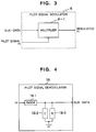
- Fig. 3 is a block diagram of an example of a pilot signal modulator used in the data transmission system;
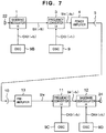
- Fig. 4 is a block diagram of an example of a pilot signal demodulator used in the data transmission system;
- Fig. 5 is a block diagram of an entire arrangement of another embodiment of the data transmission system in accordance with the present invention;
- Fig. 6 is a block diagram of an entire arrangement of a signal relay system to which the data transmission system of the present invention is applied;
- Fig. 7 is a block diagram of an entire arrangement of a general data transmission system;
- Fig. 8 is a diagram for explaining the basic operation of the data transmission system of Fig. 7;
- Fig. 9 is a block diagram of a further embodiment of the data transmission system in accordance with the present invention; and
- Fig. 10 is a block diagram of an STL to which the data transmission system of the present invention is applied.
-
- The basic operation of a data transmission system of the present invention as an example will be explained with reference to Fig. 2.
- In a transmission side, a main signal Sit subjected to a baseband modulation is created based on a reference clock (for example, having a frequency f2 of 20 MHz obtained by frequency-dividing a signal having a frequency f1 of, e.g., 1,800 MHz from an oscillator (OSC) 9 by, e.g., 90) for the baseband modulation.
- Also previously added to the main signal Sit is a pilot signal (sub-signal) Pt obtained by frequency-dividing the signal of the frequency f1 (of 1,800 MHz) from the
OSC 9 by, e.g., 60. And a signal Si&Pt having the added pilot signal Pt is up-converted to a signal Sh&Pt of a frequency of 1,820 and then transmitted. - A receive signal Sh&Pr amplified in a receiver side is down-converted based on an output of a voltage-controlled oscillator (VCO) 15 into a signal Si&Pr. And a pilot signal Pr is extracted from the signal Si&Pr, and compared with a result obtained by frequency-dividing the output of the
VCO 15 by 60 to correct an frequency f1c of the output of theVCO 15. - That is, since control is carried out in such a manner that the frequency f1 of the
OSC 9 in the transmission side becomes equal to the frequency f1c of theVCO 15 in the receiver side, the frequency of the signal Si&Pt of the transmission side is also equal to the frequency of the signal Si&Pr of the receiver side. In this connection, if there is a frequency shift but the pilot signal is set to have a frequency located out of the band of a main data modulated wave, the pilot signal can be instantly discriminated from the main data modulated wave. - Since a non-modulated pilot signal sometimes adversely affects other communication, it may be legally restricted. To avoid this, the pilot signal is used as modulated. Sub-data for modulation of the pilot signal Pt are considered to include digitized audio signal data for contact and control data for control of devices in signal receiver and relay stations.
- In this way, the modulation of the pilot signal with the sub-data can realize a transmission system which can transmit the sub-data while eliminating the need for provision of an additional channel exclusive to transmit the sub-data.
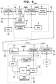
- Fig. 1 shows a block diagram of an entire arrangement of an embodiment of the data transmission system in accordance with the present invention, which will be detailed below.
- A transmitter
basic section 20, similarly to Fig. 7, includes abaseband modulator 1, afrequency converter 3, apower amplifier 4, anantenna 5 and an oscillator (OSC) 9. The transmitterbasic section 20 also includes apilot signal adder 2, apilot signal modulator 6, andfrequency dividers - An output of the oscillator (OSC) 9 is connected to a terminal Lo of the
frequency converter 3 and thefrequency dividers frequency divider 7 is sent to thepilot signal adder 2 via thepilot signal modulator 6 as a pilot signal Pt to be used as a reference of frequency conversion in the transmitterbasic section 20. - Sub-data received from a terminal 23 is applied to the
pilot signal modulator 6. In this connection, the sub-data are considered to include digitized voice signal data for contact between the transmission and receiver sides and control data for control of devices in signal receiver and relay stations. - An output of the
frequency divider 8 is applied to thebaseband modulator 1 as a reference clock of the transmitterbasic section 20. - A receiver
basic section 21, on the other hand, includes, similarly to Fig. 7, apreamplifier 13, afrequency converter 11 and abaseband demodulator 12. The receiverbasic section 21 further include apilot signal demodulator 18,frequency dividers - An output of the
VCO 15 is applied to thefrequency dividers frequency divider 7 is applied to thePLL 14. An output of thefrequency converter 11 is applied to thebaseband demodulator 12 andBPF 17. An output of theBPF 17 is applied to the other input of thePLL 14 and to thepilot signal demodulator 18. An output ε of thePLL 14 is connected to a control terminal of theVCO 15. - The processing operations of the parts of the data transmission system of Fig. 1 will be explained by referring also to Fig. 2.
- The frequency f2 (of, e.g., 20 MHz obtained by frequency-dividing the output (having the frequency f1 of, e.g., 1,800 MHz) of the
OSC 9 by, e.g., 90) of thefrequency divider 8 is used as a frequency reference in the baseband modulation. As a result, a modulated signal Sit having a frequency of 20 MHz is created by thebaseband modulator 1. The output of theOSC 9 is frequency-divided by, e.g., 60 in thefrequency divider 7 into a pilot signal Pt of a frequency of 30 MHz modulated with the sub-data. - The
pilot signal adder 2 adds together the signal Sit modulated with the main data and the pilot signal Pt modulated with the sub-data to generate a signal Si&Pt, and then outputs the signal Si&Pt. - The
frequency converter 3 up-converts the signal Si&Pt to a signal Sh&Pt having a radio frequency of, e.g., 1,820 MHz. - The radio-frequency signal Sh&Pt is transmitted from the transmission side to the receiver side, and amplified by the
preamplifier 13 of the receiver side to a signal Sh&Pr. And the signal Sh&Pr is frequency-converted by thefrequency converter 11 to a signal Si&Pr having an intermediate frequency. The signal Si&Pr contains a component corresponding to the sender-side signal Sit of 20 MHz modulated with the main data and a component corresponding to the pilot signal Pr of 30 MHz modulated with the sub-data. - In this case, when the frequency f1c of the
VCO 15 is not equal to the frequency f1 of theOSC 9 of the transmission side, the main data and sub-data subjected to the frequency conversion both do not have carrier frequencies of 20 MHz and 30 MHz respectively, thus generating a frequency shift corresponding to a difference between the frequencies f1 and f1c. - The
BPF 17, by utilizing the frequency difference, extracts the pilot signal Pr component of about 30 MHz from the composite signal Si&Pr of the intermediate frequency. ThePLL 14 compares the frequency of the extracted pilot signal Pr component with a frequency obtained by dividing the output frequency of theVCO 15 by 60, and controls the frequency f1c of theVCO 15 in such a manner that the both frequencies become equal. - Now explanation will be made below as to a relationship between the frequency of the extracted pilot signal Pr down-converted by the
frequency converter 11 and the frequency of the signal obtained by frequency-dividing the output of theVCO 15 by 60. - For example, when the oscillation frequency f1c of the
VCO 15 is initially 1,803 MHz, a frequency obtained by frequency-dividing the oscillation frequency f1c of theVCO 15 by 60 is 30.05 MHz (= f1c/60 = 1,803 MHz/60). - Meanwhile, the frequency of the extracted pilot signal Pr by subtracting the oscillation frequency f1c of the
VCO 15 from a sum of the frequency f1 of theOSC 9 of the transmission side and the frequency (30 MHz) of the pilot signal Pt of the transmission side becomes 27 MHz (= f1 + 30 MHz - f1c = 1,800 MHz + 30 MHz - 1,803 MHz). - In this case, the
PLL 14 is controlled so that the oscillation frequency f1c of theVCO 15 decreases. - As a result, when the oscillation frequency f1c of the
VCO 15 is fluctuated, for example, from 1,803 MHz to 1,801 MHz, the frequency obtained by frequency-dividing the oscillation frequency f1c of theVCO 15 by 60 becomes 30.017 MHz (= f1c/60 = 1,801 MHz/60). - Meanwhile, the frequency of the extracted pilot signal Pr becomes 29 MHz (= f1 + 30 MHz - f1c = 1,800 MHz + 30 MHz - 1,801 MHz).
- As a result of repetition of such control, when the oscillation frequency tic of the
VCO 15 is varied from 1,801 MHz to 1,800 MHz, the frequency obtained by frequency-dividing the frequency f1c by 60 becomes 30.00 MHz (= f1c/60 = 1,800 MHz/60). - Meanwhile, the frequency of the extracted pilot signal Pr becomes 30 MHz (= f1 + 30 MHz - f1c = 1,800 MHz + 30 MHz - 1,800 MHz).
- As a result, the frequency of the pilot signal Pr in the transmission side becomes equal to that in the receiver side, so that the reference frequency of the frequency down-conversion of the receiver side is controlled to be equal to the reference frequency of the frequency up-conversion of the transmission side, thus generating no frequency shift between the transmission and receiver sides. The pilot signal Pr extracted by the
BPF 17 is supplied to thepilot signal demodulator 18 where the sub-data is demodulated therefrom and then output to a terminal 25. - Explanation will next be made as to an example of the
pilot signal modulator 6 of Fig. 3. Since the pilot signal is used as the frequency reference in the transmission side, thepilot signal modulator 6 is of a modulation type wherein a center of fluctuation frequencies of the pilot signal is fixed independently of contents of the sub-data. A simplest form of the modulation type is amplitude modulation. - A multiplier 6-1 multiplies the sub-data by the pilot signal to generate a pilot signal Pt modulated with the sub-data, and outputs the pilot signal Pr.
- Explanation will then be made as to an example of the
pilot signal demodulator 18 of Fig. 4. - It goes without saying that the
pilot signal demodulator 18 is of a demodulation type associated with the modulation type used in the transmission side. In the illustrated example, the demodulation type is amplitude demodulation. - In this case, since the pilot signal Pr is sent via a diode 18-1 to a capacitor 18-2 and a resistor 18-3 to be accumulated therein and discharged therefrom, an envelope of the sub-data can be reproduced and the sub-data can be demodulated.
- As mentioned above, since a digitized voice signal for contact between the transmission and receiver sides as well as control data for control of devices in signal receiving and relay stations can be carried on the pilot signal as the sub-data, these signals can be transmitted while eliminating the need for provision of a private line or channel.
- In this connection, when the sub-data is modulated at a high rate, the frequency fluctuation width of the pilot signal Pt is increased, for which reason it is necessary to restrict the modulation degree to such a level that will not interfere with the frequency band of the modulated main data signal Sit.
- Another embodiment of the data transmission system in accordance with the present invention shown in Fig. 5 will be explained. This embodiment is arranged so that addition of the pilot signal in a transmission side is carried out after frequency up-conversion, while extraction of the pilot signal in a receiver side is carried out prior to frequency down-conversion.
- In this case, accordingly, the outputs of the OSC's 9 and 15 can be directly used as the pilot signal and its comparison signal. In this case, however, it becomes necessary to provide a high-resolution filter for removing a signal f'h&Pt of a lower side band generated after the frequency up-conversion.
- Fig. 6 shows an arrangement of a radio relay system having a plurality of relay points, to which the data transmission system of the present invention is applied.
- In this system, a
transmitter base section 20a located in a first point (a first communication station) transmits a send signal having a frequency fh1, whereas, areceiver base section 21a provided in a second point (a relay station as a second communication station) receives the signal of the frequency fh1 and converts it to a signal Si&Pr having an intermediate frequency. - The pilot signal Pr having a frequency out of the frequency band is removed by a
BPF 19 from the signal Si&Pr to leave only the signal Sir having a frequency within the band. The signal Sir is provided to atransmitter base section 20b and afrequency converter 30a. Thetransmitter base section 20b adds the pilot signal Pr modulated with the sub-data to the signal Sir, converts it to a send signal having a frequency fh2, and then transmits the converted signal toward a third point (a third communication station), similarly to the above. - In the relay station at the second point, the signal Sir is converted to a signal having a UHF band frequency and power amplified by a
UHF band amplifier 31, and only the main data subjected to the UHF band conversion is transmitted from anantenna 32 toward the periphery of the second point. UHF electromagnetic wave transmitted from theantenna 32 is received by the receivers of subscribers within a wave reach area. - At the third point, a received signal is frequency-converted by a
receiver base section 21b to a signal Sir&Pr having an intermediate frequency, passed through aBPF 19 to obtain only the signal Sir, and then applied to afrequency converter 30b, similarly to the above. As in the second point, the signal Sir is converted by thefrequency converter 30b to a signal having a UHF band frequency, power amplified by anUHF band amplifier 31, and then sent to aUHF band antenna 32 to transmit only the main data converted to the UHF band to the periphery of the second point. UHF electromagnetic wave transmitted from theantenna 32 is received by the receivers of subscribers within the wave reach area. - In this connection, if the contents of the sub-data is set identical for all relay points, information having the same contents can be delivered to the relay points. Further, when the contents of the sub-data is changed for each of the relay points, different information can be transmitted to the respective relay points.
- Shown in Fig. 9 is a block diagram of a further embodiment of the data transmission system in accordance with the present invention. The embodiment of Fig. 9 is basically the same as the embodiment of Fig. 1, except for the structures of the frequency divider and OSC. The same elements in Fig. 9 as those in Fig. 1 are denoted by the same reference numerals. In the embodiment of Fig. 9, a local oscillation signal for use in a
baseband modulator 1 and a local oscillation signal for use in afrequency converter 3 are supplied from individual OSC's 40 and 9 respectively. Accordingly, the embodiment of Fig. 9 has no such afrequency divider 8 as used in the embodiment of Fig. 1.Reference symbol 20m denotes a transmitter basic section andsymbol 21m denotes a receiver basic section. The transmitter and receiverbasic sections basic sections - The
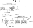
baseband modulator 1 converts an input signal to a signal having an intermediate frequency Sit according to a clock generated by theOSC 40. Thebaseband demodulator 12 converts an input signal having the intermediate frequency Sit to a signal of a baseband according to a clock generated by anOSC 41. In the absence of thefrequency divider 8, an error in the OSC's 40 and 41 remains in an output of a receiver side. However, since the OSC's 40 and 41 generate the clocks having frequencies of several tens of MHz, even when the error is 1 ppm, a frequency difference therebetween is several Hz that is practically insignificant. - Next Fig. 10 shows a block diagram of yet another embodiment of the data transmission system in accordance with the present invention. In the system of the embodiment of Fig. 10, a communication station corresponding to the second point in the embodiment of Fig. 6 does not perform relay transmission to a third point. The communication station as a second point, after receiving a microwave signal from a first point (communication station), converts the received signal to a UHF electromagnetic wave signal and then transmits it to an associated subscriber.
- Fig. 10 shows an example of a studio-to-transmitter link (STL) of transmitting a signal in the form of microwave and then transmitting the signal having a UHF band frequency to general homes. In order to completely remove sub-data, the signal is passed through a
BPF 19 to obtain only a main data component, frequency-converted by afrequency converter 30 to a signal having the UHF band frequency, amplified by aUHF band amplifier 31 to an output of a large to intermediate level, and then transmitted from anantenna 32 in the form of broadcasting wave. - It goes without saying that the present invention is not limited to the foregoing embodiments mentioned above. The pilot signal, that is, the sub-signal modulated with the sub-data in the present invention may have a frequency that is higher or lower than the band of the main signal. Further, the baseband modulator may employ a digital modulation system other than the OFDM modulation system or an analog modulation system. Data to be transmitted in the data transmission system of the present invention are considered to TV broadcasting signals or signals indicative of various media information other than the broadcasting signals. The signal transmission between the communication stations or between the communication and relay stations may be realized not only by the radio transmission but also by wired communication medium including an optical fiber cable.
- As has been explained in the foregoing, in accordance with the present invention, since the reference frequency in the receiver side is controlled on the basis of the pilot frequency extracted in the receiver side, the frequency conversion reference of the transmission side can be made to coincide with that of the receiver side. At the same time, there can be realized a transmission system which can transmit sub-data while eliminating the need for provision of an additional channel for the sub-data.
Claims (23)
- A data transmission system for transmitting data from a transmitter (20) to a receiver (21) located away therefrom, wherein said transmitter (20) includes circuitry for transmitting together a main signal (Sit) having a carrier modulated with main data (22) to be transmitted and as well as a sub-signal (Pt) to be used in frequency conversion and generated by modulating a carrier of a predetermined frequency out of a frequency band of said main signal, and said receiver (21) includes circuitry (11, 17) for receiving a receive signal (Sh&Pr) from said transmitter and extracting said sub-signal (Pr) therefrom and also includes circuitry (14, 15, 7) for generating a signal (f1c) to be used as a reference at the time of converting said receive signal to a signal having a predetermined frequency on the basis of said extracted sub-signal.
- A data transmission system as set forth in claim 1, wherein said sub-signal (Pt) has a frequency away from an occupation band (Si) of said main data by a known predetermined frequency.
- A data transmission system as set forth in claim 1, wherein said transmitter includes means for modulating said main data with a signal frequency band of said main data signal and a frequency up-converter (3) for converting the modulated signal of said main data to a signal having a frequency higher therethan, said sub-signal contains frequency information relating to frequency conversion of said frequency up-converter, and said receiver includes a frequency down-converter (11) for converting said receive signal to a signal having lower frequency than said receive signal's frequency on the basis of frequency information of said extracted sub-signal.
- A data transmission system as set forth in claim 3, wherein said means for modulating said main data with the frequency band of said main data signal includes digital modulation means (1) for modulating the main data with a baseband signal band.
- A data transmission system as set forth in claim 4, wherein said digital modulation means modulates said main data based on OFDM and said frequency up-converter includes means for converting an OFDM-modulated signal to a signal of a microwave frequency band.
- A data transmission system as set forth in claim 1, wherein said sub-data contains an audio signal.
- A data transmission system as set forth in claim 3, wherein said receiver includes a local oscillator (15) for outputting a frequency for conversion of said receive signal to a signal of a frequency lower there than in said frequency down-converter and means (7, 14) for adjusting an output frequency of said local oscillator so that a difference between the frequency information of said extracted sub-signal and a reference frequency obtained by frequency dividing an output of said local oscillator becomes close to a predetermined value.
- A data transmission system as set forth in claim 3, wherein said transmitter includes a local oscillator (9) for outputting a predetermined frequency and frequency dividers (7, 8) for dividing an output frequency of said local oscillator to output a first reference frequency (f2) to be used at the time of modulating said main data with the signal frequency band of the main data and to output a second reference frequency (Pt) for conversion of the modulated signal of said main data to a signal having a frequency higher therethan in said frequency up-converter.
- A data transmission system as set forth in claim 3, wherein said transmitter includes a first local oscillator (40) for generating a first reference frequency to be used at the time of modulating said main data with the signal frequency band of the main data, a second local oscillator (9) having an output different from that of said first local oscillator, a frequency divider (7) for dividing an output of said second local oscillator to output a second reference frequency for conversion of a modulated signal of said main data to a signal having a frequency higher therethan in said frequency up-converter.
- A data transmission system as set forth in claim 3, wherein said transmitter has an adder for adding said sub-signal to said main signal, said adder being provided at an upstream stage of said frequency up-converter.
- A data transmission system as set forth in claim 3, wherein said transmitter has an adder (2) for adding said sub-signal to said main signal, said adder being provided at a downstream stage of said frequency up-converter.
- A data transmission system as set forth in claim 1, wherein said main signal includes digital television signal and a digital audio signal.
- A communication station in a data transmission system for transmitting data between communication stations located away from each other, comprising:a transmitter (20b) having circuits for transmitting together a main signal having a carrier modulated with main data to be transmitted and a sub-signal to be used in frequency conversion generated by modulating a carrier having a predetermined frequency out of a frequency band of said main signal with sub-data different from said main data; anda receiver (21a) having a circuit for receiving a receive signal from a transmitter of another communication station and extracting a sub-signal from said receive signal and a circuit for generating a reference signal at the time of converting said receive signal to a signal of a predetermined frequency on the basis of said extracted sub-signal.
- A communication station as set forth in claim 13, wherein said transmitter includes means for modulating said main data with a signal frequency band of said main data signal and a frequency up-converter (3) for converting the modulated signal of said main data to a signal having a frequency higher therethan, said sub-signal contains frequency information relating to frequency conversion of said frequency up-converter, and said receiver includes a frequency down-converter (11) for converting said receive signal to a signal having lower frequency than said receive signal's frequency on the basis of frequency information of said extracted sub-signal.
- A communication station as set forth in claim 13, further comprising a second transmitter (30a, 31; 30, 31) for receiving a receive signal from a transmitter of another communication station, converting the received signal to a signal of a frequency band lower therethan and transmitting a converted signal.
- A communication station as set forth in claim 13, wherein said main signal includes a digital television signal and a digital audio signal.
- A communication station as set forth in claim 13, wherein said sub-signal has a frequency that is out of an occupation band of said main data and is away therefrom by a known predetermined frequency.
- A method for transmitting data from a transmitter to a receiver located away therefrom, comprising the steps of:generating a main signal having a carrier modulated with main data to be transmitted;generating a sub-signal to be used in frequency conversion and generated by modulating a carrier of a predetermined frequency out of a frequency band of said main signal with sub-data different from said main data;transmitting said main signal and said sub-signal together to said transmitter (20);receiving a receive signal from said transmitter in said receiver (21);extracting said sub-signal from the receive signal; andgenerating a reference signal at the time of converting said receive signal to a signal having a predetermined frequency on the basis of said extracted sub-signal.
- A data transmission method as set forth in claim 18, wherein said sub-signal has a frequency away from an occupation band of said main data by a known predetermined frequency.
- A data transmission method as set forth in claim 18, wherein said main signal generating step includes a step of modulating said main data with a signal frequency band of said main data signal and a frequency up-converter step of converting the modulated signal of said main data to a signal having a frequency higher therethan, said sub-signal containing frequency information relating to frequency conversion of said frequency up-converter, and said receiving step includes a frequency down-converter step of converting said receive signal to a signal having lower frequency than said receive signal's frequency on the basis of frequency information of said extracted sub-signal.
- A data transmission method as set forth in claim 20, wherein said step of modulating said main data with the frequency band of said main data signal includes a step of digitally modulating the main data with a baseband signal band.
- A data transmission method as set forth in claim 21, wherein said digital modulating step is carried out by modulating said main data based on OFDM and said frequency up-converter step includes a step of converting an OFDM-modulated signal to a signal of a microwave frequency band.
- A data transmission method as set forth in claim 18, wherein said sub-data contains a voice signal.
Applications Claiming Priority (2)
| Application Number | Priority Date | Filing Date | Title |
|---|---|---|---|
| JP10259016A JP2000092142A (en) | 1998-09-11 | 1998-09-11 | Data transmission system |
| JP25901698 | 1998-09-11 |
Publications (2)
| Publication Number | Publication Date |
|---|---|
| EP0986207A2 true EP0986207A2 (en) | 2000-03-15 |
| EP0986207A3 EP0986207A3 (en) | 2003-09-24 |
Family
ID=17328188
Family Applications (1)
| Application Number | Title | Priority Date | Filing Date |
|---|---|---|---|
| EP99117442A Withdrawn EP0986207A3 (en) | 1998-09-11 | 1999-09-08 | Transmission of a subchannel, using a pilot signal |
Country Status (3)
| Country | Link |
|---|---|
| US (1) | US6813326B1 (en) |
| EP (1) | EP0986207A3 (en) |
| JP (1) | JP2000092142A (en) |
Families Citing this family (10)
| Publication number | Priority date | Publication date | Assignee | Title |
|---|---|---|---|---|
| US6724804B1 (en) * | 1998-07-13 | 2004-04-20 | Kabushiki Kaisha Kobe Seiko Sho | Frequency converter and radio communications system employing the same |
| US7027776B2 (en) * | 2000-01-26 | 2006-04-11 | Vyyo, Inc. | Transverter control mechanism for a wireless modem in a broadband access system |
| US7359314B2 (en) * | 2001-12-26 | 2008-04-15 | Hitachi, Ltd. | Signal transmission system for transmitting a signal with a guard interval and a demodulation method thereof |
| EP2800277B1 (en) | 2003-04-01 | 2024-02-21 | Nec Corporation | Data processing terminal system and transmitting and receiving method using the same |
| KR20070006784A (en) * | 2004-03-25 | 2007-01-11 | 마쓰시다 일렉트릭 인더스트리얼 컴패니 리미티드 | Radio system and radio communication device |
| JP4560103B2 (en) * | 2008-05-12 | 2010-10-13 | 株式会社東芝 | Relay device |
| JP2011259091A (en) * | 2010-06-07 | 2011-12-22 | Sony Corp | Signal transmission system, signal processor, reference signal transmitter, reference signal receiver, electronic apparatus, signal transmission method |
| JP4846864B2 (en) * | 2010-06-14 | 2011-12-28 | 株式会社東芝 | Signal transmission apparatus and signal transmission method |
| JP6080169B2 (en) * | 2014-03-14 | 2017-02-15 | 古河電気工業株式会社 | Transmission / reception system, transmission device, and reception device |
| JP5840283B1 (en) * | 2014-12-18 | 2016-01-06 | 古河電気工業株式会社 | Receiver |
Citations (3)
| Publication number | Priority date | Publication date | Assignee | Title |
|---|---|---|---|---|
| US4837786A (en) * | 1986-08-07 | 1989-06-06 | Comstream Corporation | Technique for mitigating rain fading in a satellite communications system using quadrature phase shift keying |
| WO1997008861A1 (en) * | 1995-08-25 | 1997-03-06 | Terayon Corporation | Apparatus and method for digital data transmission |
| US5796783A (en) * | 1995-10-31 | 1998-08-18 | Andre Alain Tabourian | Digital transmission system |
Family Cites Families (8)
| Publication number | Priority date | Publication date | Assignee | Title |
|---|---|---|---|---|
| JPS5636242A (en) | 1979-08-31 | 1981-04-09 | Nec Corp | Satellite communication system |
| US5408686A (en) * | 1991-02-19 | 1995-04-18 | Mankovitz; Roy J. | Apparatus and methods for music and lyrics broadcasting |
| US5339184A (en) * | 1992-06-15 | 1994-08-16 | Gte Laboratories Incorporated | Fiber optic antenna remoting for multi-sector cell sites |
| KR0165277B1 (en) * | 1993-02-27 | 1999-03-20 | 김광호 | Apparatus for recording and reproducing a digital signal |
| JP3390260B2 (en) | 1994-08-09 | 2003-03-24 | 日本放送協会 | Method and apparatus for recovering a reference carrier frequency for OFDM modulated signal demodulation |
| JP3145003B2 (en) | 1995-03-23 | 2001-03-12 | 株式会社東芝 | Orthogonal frequency division multiplexing transmission system and transmitter and receiver thereof |
| JP3289610B2 (en) * | 1996-07-31 | 2002-06-10 | 日本ビクター株式会社 | OFDM demodulator and method |
| US5844939A (en) * | 1997-02-14 | 1998-12-01 | Hewlett-Packard Company | Low-cost phaselocked local oscillator for millimeter wave transceivers |
-
1998
- 1998-09-11 JP JP10259016A patent/JP2000092142A/en active Pending
-
1999
- 1999-09-08 EP EP99117442A patent/EP0986207A3/en not_active Withdrawn
- 1999-09-10 US US09/394,276 patent/US6813326B1/en not_active Expired - Fee Related
Patent Citations (3)
| Publication number | Priority date | Publication date | Assignee | Title |
|---|---|---|---|---|
| US4837786A (en) * | 1986-08-07 | 1989-06-06 | Comstream Corporation | Technique for mitigating rain fading in a satellite communications system using quadrature phase shift keying |
| WO1997008861A1 (en) * | 1995-08-25 | 1997-03-06 | Terayon Corporation | Apparatus and method for digital data transmission |
| US5796783A (en) * | 1995-10-31 | 1998-08-18 | Andre Alain Tabourian | Digital transmission system |
Also Published As
| Publication number | Publication date |
|---|---|
| JP2000092142A (en) | 2000-03-31 |
| US6813326B1 (en) | 2004-11-02 |
| EP0986207A3 (en) | 2003-09-24 |
Similar Documents
| Publication | Publication Date | Title |
|---|---|---|
| JP4354530B2 (en) | Frequency drift correction at subscriber terminals | |
| US4941150A (en) | Spread spectrum communication system | |
| US6377314B1 (en) | Methods and apparatus for transmitting analog and digital information signals | |
| US6823178B2 (en) | High-speed point-to-point modem-less microwave radio frequency link using direct frequency modulation | |
| US6973328B1 (en) | Millimeter wave band transmitter, millimeter wave band receiver and millimeter wave band communication apparatus carrying out radio communication in millimeter wave band region | |
| CN1143432A (en) | Local oscillator phase noise cancelling modulation technique | |
| JP2000512813A6 (en) | Frequency drift correction in subscriber terminals | |
| US4618996A (en) | Dual pilot phase lock loop for radio frequency transmission | |
| US6370361B1 (en) | Transceiver with a receive/transmit fast switch function | |
| US5953045A (en) | Channel selection type radio transmission apparatus | |
| US6813326B1 (en) | Data transmission system, data transmission communication station, and data transmission method | |
| CN100395958C (en) | Method and system for re-modulation using zero if | |
| US7177591B2 (en) | Frequency converter and radio communications system employing the same | |
| JP4160181B2 (en) | Signal transmission method and relay device | |
| JP2005287065A (en) | Millimeter band communication device | |
| US5604746A (en) | Digital data receiver | |
| EP1168649A2 (en) | Two-way radio communication system and two-way radio communication method. | |
| US20070230970A1 (en) | Transmission Device, Reception Device, Signal Transmission Device, and Signal Transmission Method | |
| US6433830B1 (en) | Off-air phase lock technique | |
| US6917787B2 (en) | System and method for superheterodyne frequency multiplication signal expansion to achieve a reduced bandwidth frequency or phase modulation communication channel | |
| US6522637B1 (en) | System and method for allocating a carrier wave frequency of one channel between two carrier wave frequencies of another channel | |
| JPS61103324A (en) | Synthesizer circuit of radio communication equipment | |
| JP3745610B2 (en) | Millimeter-wave wireless communication method | |
| KR100732885B1 (en) | Apparatus for reduling phase noise in gap filler | |
| JP4560103B2 (en) | Relay device |
Legal Events
| Date | Code | Title | Description |
|---|---|---|---|
| PUAI | Public reference made under article 153(3) epc to a published international application that has entered the european phase |
Free format text: ORIGINAL CODE: 0009012 |
|
| 17P | Request for examination filed |
Effective date: 19990908 |
|
| AK | Designated contracting states |
Kind code of ref document: A2 Designated state(s): AT BE CH CY DE DK ES FI FR GB GR IE IT LI LU MC NL PT SE |
|
| AX | Request for extension of the european patent |
Free format text: AL;LT;LV;MK;RO;SI |
|
| RIN1 | Information on inventor provided before grant (corrected) |
Inventor name: TSUKAMOTO, NOBUO Inventor name: NAKADA, TATSUHIRO Inventor name: TAKESUE, HIROYUKI Inventor name: ISHIDA, ITSUO Inventor name: KODA, HISAO Inventor name: SANO, SEEICHI Inventor name: AKIYAMA, TOSHIYUKI Inventor name: MIYASHITA, ATSUSHI |
|
| PUAL | Search report despatched |
Free format text: ORIGINAL CODE: 0009013 |
|
| AK | Designated contracting states |
Kind code of ref document: A3 Designated state(s): AT BE CH CY DE DK ES FI FR GB GR IE IT LI LU MC NL PT SE |
|
| AX | Request for extension of the european patent |
Extension state: AL LT LV MK RO SI |
|
| RIC1 | Information provided on ipc code assigned before grant |
Ipc: 7H 04L 27/00 B Ipc: 7H 04L 5/06 A |
|
| AKX | Designation fees paid |
Designated state(s): DE FR GB |
|
| STAA | Information on the status of an ep patent application or granted ep patent |
Free format text: STATUS: THE APPLICATION IS DEEMED TO BE WITHDRAWN |
|
| 18D | Application deemed to be withdrawn |
Effective date: 20060401 |