EP0986217A2 - Network transceiver for steering network data to selected paths based on determined link speeds - Google Patents
Network transceiver for steering network data to selected paths based on determined link speeds Download PDFInfo
- Publication number
- EP0986217A2 EP0986217A2 EP99301073A EP99301073A EP0986217A2 EP 0986217 A2 EP0986217 A2 EP 0986217A2 EP 99301073 A EP99301073 A EP 99301073A EP 99301073 A EP99301073 A EP 99301073A EP 0986217 A2 EP0986217 A2 EP 0986217A2
- Authority
- EP
- European Patent Office
- Prior art keywords
- network
- data
- transceiver
- link
- repeater
- Prior art date
- Legal status (The legal status is an assumption and is not a legal conclusion. Google has not performed a legal analysis and makes no representation as to the accuracy of the status listed.)
- Granted
Links
Images


Classifications
-
- H—ELECTRICITY
- H04—ELECTRIC COMMUNICATION TECHNIQUE
- H04L—TRANSMISSION OF DIGITAL INFORMATION, e.g. TELEGRAPHIC COMMUNICATION
- H04L25/00—Baseband systems
- H04L25/02—Details ; arrangements for supplying electrical power along data transmission lines
- H04L25/03—Shaping networks in transmitter or receiver, e.g. adaptive shaping networks
- H04L25/03878—Line equalisers; line build-out devices
- H04L25/03885—Line equalisers; line build-out devices adaptive
-
- G—PHYSICS
- G01—MEASURING; TESTING
- G01B—MEASURING LENGTH, THICKNESS OR SIMILAR LINEAR DIMENSIONS; MEASURING ANGLES; MEASURING AREAS; MEASURING IRREGULARITIES OF SURFACES OR CONTOURS
- G01B7/00—Measuring arrangements characterised by the use of electric or magnetic techniques
- G01B7/02—Measuring arrangements characterised by the use of electric or magnetic techniques for measuring length, width or thickness
-
- H—ELECTRICITY
- H04—ELECTRIC COMMUNICATION TECHNIQUE
- H04B—TRANSMISSION
- H04B3/00—Line transmission systems
- H04B3/02—Details
- H04B3/46—Monitoring; Testing
-
- H—ELECTRICITY
- H04—ELECTRIC COMMUNICATION TECHNIQUE
- H04J—MULTIPLEX COMMUNICATION
- H04J3/00—Time-division multiplex systems
- H04J3/02—Details
- H04J3/06—Synchronising arrangements
- H04J3/0635—Clock or time synchronisation in a network
- H04J3/0685—Clock or time synchronisation in a node; Intranode synchronisation
- H04J3/0688—Change of the master or reference, e.g. take-over or failure of the master
-
- H—ELECTRICITY
- H04—ELECTRIC COMMUNICATION TECHNIQUE
- H04L—TRANSMISSION OF DIGITAL INFORMATION, e.g. TELEGRAPHIC COMMUNICATION
- H04L12/00—Data switching networks
- H04L12/28—Data switching networks characterised by path configuration, e.g. LAN [Local Area Networks] or WAN [Wide Area Networks]
- H04L12/46—Interconnection of networks
- H04L12/4604—LAN interconnection over a backbone network, e.g. Internet, Frame Relay
- H04L12/462—LAN interconnection over a bridge based backbone
- H04L12/4625—Single bridge functionality, e.g. connection of two networks over a single bridge
-
- H—ELECTRICITY
- H04—ELECTRIC COMMUNICATION TECHNIQUE
- H04L—TRANSMISSION OF DIGITAL INFORMATION, e.g. TELEGRAPHIC COMMUNICATION
- H04L41/00—Arrangements for maintenance, administration or management of data switching networks, e.g. of packet switching networks
- H04L41/04—Network management architectures or arrangements
- H04L41/046—Network management architectures or arrangements comprising network management agents or mobile agents therefor
-
- H—ELECTRICITY
- H04—ELECTRIC COMMUNICATION TECHNIQUE
- H04L—TRANSMISSION OF DIGITAL INFORMATION, e.g. TELEGRAPHIC COMMUNICATION
- H04L69/00—Network arrangements, protocols or services independent of the application payload and not provided for in the other groups of this subclass
- H04L69/18—Multiprotocol handlers, e.g. single devices capable of handling multiple protocols
-
- H—ELECTRICITY
- H04—ELECTRIC COMMUNICATION TECHNIQUE
- H04L—TRANSMISSION OF DIGITAL INFORMATION, e.g. TELEGRAPHIC COMMUNICATION
- H04L69/00—Network arrangements, protocols or services independent of the application payload and not provided for in the other groups of this subclass
- H04L69/30—Definitions, standards or architectural aspects of layered protocol stacks
- H04L69/32—Architecture of open systems interconnection [OSI] 7-layer type protocol stacks, e.g. the interfaces between the data link level and the physical level
- H04L69/322—Intralayer communication protocols among peer entities or protocol data unit [PDU] definitions
- H04L69/323—Intralayer communication protocols among peer entities or protocol data unit [PDU] definitions in the physical layer [OSI layer 1]
-
- G—PHYSICS
- G01—MEASURING; TESTING
- G01R—MEASURING ELECTRIC VARIABLES; MEASURING MAGNETIC VARIABLES
- G01R31/00—Arrangements for testing electric properties; Arrangements for locating electric faults; Arrangements for electrical testing characterised by what is being tested not provided for elsewhere
- G01R31/08—Locating faults in cables, transmission lines, or networks
- G01R31/081—Locating faults in cables, transmission lines, or networks according to type of conductors
- G01R31/086—Locating faults in cables, transmission lines, or networks according to type of conductors in power transmission or distribution networks, i.e. with interconnected conductors
-
- H—ELECTRICITY
- H04—ELECTRIC COMMUNICATION TECHNIQUE
- H04L—TRANSMISSION OF DIGITAL INFORMATION, e.g. TELEGRAPHIC COMMUNICATION
- H04L12/00—Data switching networks
- H04L12/28—Data switching networks characterised by path configuration, e.g. LAN [Local Area Networks] or WAN [Wide Area Networks]
- H04L12/40—Bus networks
- H04L12/4013—Management of data rate on the bus
- H04L12/40136—Nodes adapting their rate to the physical link properties
-
- H—ELECTRICITY
- H04—ELECTRIC COMMUNICATION TECHNIQUE
- H04L—TRANSMISSION OF DIGITAL INFORMATION, e.g. TELEGRAPHIC COMMUNICATION
- H04L49/00—Packet switching elements
- H04L49/30—Peripheral units, e.g. input or output ports
- H04L49/3054—Auto-negotiation, e.g. access control between switch gigabit interface connector [GBIC] and link
Definitions
- the present invention relates to network interfacing, and more particularly to a novel network transceiver that steers network data streams to a selected data path compatible with the operating speed of a network link partner.
- a Local Area Network is a communications systems that provides a connection among a number of independent computing stations within a small area, such as a single building or group of adjacent buildings.
- One type of network structure uses one or more repeaters in a star topology, with each repeater having several ports. A data packet received at one port is retransmitted to all other ports of the repeater. Each repeater in turn restores timing and amplitude degradation ofdata packets received at one port and retransmits the packets to all other ports.
- Ethernet networks (10BASE-T) operate at 10Mb/s Ethernet protocol, as described by IEEE Standard 802.3;the majority of Ethernet interfaces currently operate at this data rate.
- IEEE Standard 802.3u a newer Ethernet standard, under IEEE standard 802.3u, accomplishes the faster operation of 100 BASE-T systems, at a 100 Mb/s data rate (i.e., a 125Mb/s encoded bit rate) using unshielded twisted pair (UTP) physical media.
- the 100 BASE-T standard defines operation over two pairs of category 5 UTP (100 BASE-TX) and over four pairs of category 3 UTP.
- the 100 BASE-FX network medium covered by the 100 BASE-T standard, allows operation over dual fiber optic cabling.
- Ethernet protocol provides for a Media Access Control (MAC), enabling network interface devices at each network node to share accesses to the network medium.
- MAC Media Access Control
- One type of connection termed a Media Independent Interface, or MII
- MII Media Independent Interface
- PHY physical layer
- the physical layer transceiver is configured for converting the MII protocol signals output by the MAC into analog network signals, such as Multiple Layer Transition-3 (MLT-3) signals for 100 Mb/s Ethernet networks, or Manchester-encoded signals for 10 Mb/s Ethernet networks.
- MLT-3 Multiple Layer Transition-3
- Ethernet switches have multiple interfaces, each capable ofeither 10Mb/s or 100 Mb/s operation, and are able to be connected in communication with a link partner operating at a corresponding data rate. Because a switch allows multiple simultaneous traffic between its ports, it is possible to allow the ports to operate a different speeds relative to each other.
- a repeater on the other hand, is configured to operate at only a single data rate.
- a 10Mb/s repeater for example, cannot be placed in communication with a link partner operating at 100 Mb/s.
- the vast majority of Ethernet interfaces in today's networks operate only at 10 Mb/s, hence are unable to communicate with a repeater or switch that operates only at 100 Mb/s.
- a 10/100 Mb/s switch is defined as one in which each switch port has a means of negotiating the speed of operation with a link partner connected to the port via a network medium.
- Auto-negotiation is performed by the switch as a link startup procedure each time a link to the switch port is connected, powered on or reset.
- the switch automatically configures the link partner according to network configuration parameters; if the link partner cannot run at 100 Mb/s, the switch configures the link to run at 10 MB/s.
- Repeaters are more economical than switches. But the limitation in operating speed versatility of a repeater makes it unsuitable in operating environments where it is necessary to adapt to the data rate of a link partner. It would be desirable to provide a repeater or repeater system having the variable data rate attributes of a switch. To achieve this objective, the invention implements automatic steering of a network data stream to a selected repeater interface having a data rate operating at the same data rate as the link speed ofthe network link partner.
- the invention concerns a novel method of operating repeaters or other hub devices in a local area network, such as one conforming to Ethernet protocol, in which there are a one or a plurality of repeaters having repeater interfaces operating at respectively different data rates for communicating with a link partner on a network medium.
- the methodology comprises determining the data rate link speed ofthe link partner, and based on that data rate, and automatically multiplexing data between the network medium and a selected one of the repeater interfaces.
- a network transceiver is configured for supplying network data, transported via a network medium between a link partner, to a selected repeater interface.
- the network transceiver includes an auto-negotiation unit for determining a link speed ofthe link partner via the network medium.
- the network transceiver also includes first and second data busses for providing data communication with first and second repeater interfaces at respective data rates, and a multiplexer circuit.
- the multiplexer circuit is configured for supplying the network data between the network medium and a selected one of the first and second data busses for data communication with the corresponding selected repeater interface at the corresponding data rate, based on the determined link speed of the link partner.
- the multiplexer circuit and the first and second data busses enables the network data from one or a plurality of link partners to be automatically supplied (i.e., steered) to the appropriate repeater interface, based on the corresponding link speed ofthe link partner.
- the repeater interfaces maybe implemented in separate repeaters operating at respective data rates, or in an integrated repeater having two separate data rate domains.
- a repeater system comprises first and second repeater interfaces outputting network data at respective data rates, and a network transceiver.
- the network transceiver is configured for supplying the network data to at least one link partner via a corresponding network medium.
- the network transceiver includes a multiplexer circuit for supplying the network data between a selected one of the first and second repeater interfaces and the link partner according to a determined link speed ofthe link partner.
- the link partner is automatically connected to the appropriate repeater based on the determined link speed, enabling different speed network nodes to be connected by the network transceiver.
- Still another aspect of the invention provides a method of supplying network data between repeater interfaces having respective data rates a network medium providing communication for a link partner.
- the method comprises determining a link speed ofthe link partner on the network medium, and connecting the link partner to a selected one of the repeater interfaces based on the determined link speed of the link partner.
- the link partner is automatically connected to a selected repeater interface, ensuring compatibility between network components having different data rate capabilities.
- Fig. 1 is a block diagram ofan exemplary local area network architecture including a repeater system for transporting network data at different data rates according to an embodiment of the present invention.
- the network 5 includes a network switch 10, a repeater 12 operating at a first data rate such as 10 Mb/s, a second repeater 14 operating at a second data rate such as 100 Mb/s, and a multiple port physical layer transceiver 16.
- the switch 10 and the repeater 12 transfer network data via a data link 18 operating at the first data rate of 10 Mb/s.
- the switch 10 and the repeater 14 transfer data via a different data link 20 operating at the second data rate of 100 Mb/s.
- the repeaters 12 and 14 transfer data to and from the network transceiver 16 via repeater interfaces 22 and 24 operating at 10 Mb/s and 100 Mb/s, respectively.
- the repeater 12 may also transfer network data to individual network workstations 26 operating at 10 Mb/s via a shared medium 28, and the repeater 14 may transfer data to network workstations 30 operating at 100 Mb/s via a network medium 32.
- the network 5 includes a first data rate domain of 10 Mb/s and a second data rate domain of 100 Mb/s.
- Conventional systems would require separate physical layer (PHY) transceivers 34 and 36 that can operate only at a specific data rate.
- the PHY 34 would operate only at 10 Mb/s
- the PHY 36 would operate only at 100 Mb/s.
- the multiple port physical layer transceiver 16 enables multiple workstations 26', 30' having different data rates of 10 Mb/s and 100 Mb/s, respectively, to be connected to a single PHY unit for communication with the repeater interfaces 22 and 24. Moreover, the physical layer transceiver 16 enables the network data from different workstations 26' and 30' to be automatically supplied (i.e., steered) to the appropriate data rate domain, enabling more flexible implementation of multiple-rate networks. A discussion ofthis steering of network data will be provided with reference to a single-port PHY transceiver in Fig. 2.
- Fig. 2 shows a single-port PHY transceiver, in accordance with an embodiment of the invention, for establishing a communication path between a link partner 50 on a network medium 52 and one repeater interface from among a plurality of repeater interfaces that is data rate compatible with the operating speed (i.e., link speed) of the link partner 50.
- the repeater interfaces 22, 24 are implemented as Media Independent Interfaces (MIIs), and may correspond to separate repeaters, or an integrated multiple port repeater having different data rates.
- the repeaters 12 and 14, as well as the PHY 16 may be integrated on a single chip, or integrated on a hybrid circuit having multiple integrated circuits on a shared substrate.
- the transceiver 16 of Fig. 2 (illustrated as a single-port PHY transceiver) comprises an auto-negotiation unit 54 that determines the speed of operation of link partner 50 on the network medium 52 using well-known auto-negotiation techniques. Additional details regarding auto-negotiation are disclosed in Breyer et al., "Switched and Fast Ethernet: How It Works and How to Use It", Ziff-Davis Press, Emeryville, California (1995), pp. 60-70, and Johnson, "Fast Ethernet: Dawn of a New Network", Prentice-Hall, Inc. (1996), pp. 158-175.
- the transceiver 16 also includes a first data rate path 56 for converting network data between MII format and 10 Mb/s Manchester-encoded signals for transmission and reception on a 10 Mb/s medium, and a second data rate path 58.
- the second data rate path 58 converts network data between MII format and a selected 100 Mb/s signal format, such as MLT-3 encoded signals.
- the transceiver 16 also includes two or more data busses 48a and 48b connecting the PHY 16 to respective MIIs 22 and 24, and a multiplexer circuit.
- the multiplexer circuit 60 routes the output of the data paths 56 or 58 through a selected media independent interface 22, 24, etc., via the appropriate data bus 48, based on whichever one of the repeater interface 22, 24, etc. is data rate compatible with link partner 50.
- network data from the link partner 50 is transmitted via the medium 52 to an output interface 64 of the PHY transceiver 16 via a magnetic coupler 62.
- the magnetic coupler 62 coupled to the unshielded twisted pair (UTP) medium 52, provides AC coupling between the PHY interface 64 and the medium 52, plus electrical isolation.
- the received analog network signals are supplied to the appropriate data path 56 or 58 to recover the network data in digital format from the received analog signals.
- the network data, recovered from the analog network signals, is then supplied by the appropriate data path 56 or 58 to the multiplexer circuit 60 for steering to the appropriate MII 22 or 24 Note that additional MIIs (not shown) may be coupled to the multiplexer circuit 60.
- Fig. 4 illustrates the relationship between an NRZI-encoded digital signal and a corresponding three-level MLT-3 encoded analog signal in the 100 Mb/s data path 58
- NRZI is a two-level signal, in which a transition indicates a logical one value and a lack oftransition indicates a logical 0 value.
- MLT-3 is a tri-level signal, in which all transitions are between 0 and +1 volt or 0 and - 1 volt, and where successive transitions are opposite in polarity, as shown in the Figure 4.
- MLT-3 encoding is to convert the NRZI bi-level digital signal into a tri-level signal more closely resembling a sinusoid having no DC component, and having energy of reduced intensity.
- the receive channel of the data path 58 recovers the digital data from the MLT-3 encoded signals received from the network medium 52, and passes to the appropriate MII (via the multiplexer circuit 60) a sequence of data nibbles or data bytes of network data from the link partner 50.
- the 10Mb/s channel receiver data path 56 requires no equalization or compensation of data incoming from the network because the rate of transmission is slower.
- the 10BASE-T receiver 56 identifies the amplitude of the incoming signal and determines whether the signal is of the correct width and amplitude. If the incoming signal from the network medium is determined to be a Manchester signal, shown in Fig. 5, the receiver 56 decodes it into NRZI signal protocol to be supplied to the appropriate MII.
- pre-emphasis may be be added to the analog network signal transmitted to the link partner 50 compensate for signal decay on the network before a signal reaches its link partner. This pre-emphasis is in the form of a waveform bulge at the leading edge of each transition, as depicted by dotted lines in Fig. 5.
- the auto-negotiation unit 54 determines the rate of data transmission at which the link partner 50 is capable of transmitting. If the link partner is capable of transmitting at 100Mb/s, the auto-negotiation unit 36 controls the PHY device 16 to receive on the 100Mb/s data path channel 58 and controls multiplexer circuit 60 to steer the output of the data path channel 58 to the data bus 48b for supply to the 100 Mb/s repeater interface 24. Similarly, network data output from the 100 Mb/s MII repeater interface 24 via the data bus 48b is supplied by the multiplexer circuit 60 to the data path 58 for transmission to the 100 Mb/s capable link partner 50.
- the auto-negotiation unit 54 determines that the link partner 50 is capable of operating only at 10Mb/s, controls the PHY device to receive on the 10Mb/s data path channel 56 and controls multiplexer circuit 60 to steer the output of the data path 56 to the data bus 48a for supply to the 10Mb/s repeater interface 22.
- network data output from the 10 Mb/s MII repeater interface 22 via the data bus 48a is supplied by the multiplexer circuit 60 to the data path 56 for transmission to the 10 Mb/s capable only link partner 50.
- Fig. 2 enables a single link partner 50 to be connected to the appropriate MII repeater interface 22, 24, etc. based on the link speed of the link partner 50.
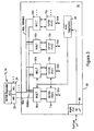
- Fig. 3 shows another embodiment of the invention, in which the PHY transceiver 16 includes multiple PHY transceiver devices 70, each selectively connected, through corresponding multiplexers 60, to either the MII 22 or the MII 24 via the corresponding shared data busses 48a or 48b.
- Each PHY layer transceiver 70 includes a 10 Mb/s data path 56 and a 100 Mb/s data path 58.
- the shared data busses 48a and 48b may provide data communication with the shared MIIs 22 and 24 for multiple transceivers 70.
- other signals may be shared on the busses 48, for example carrier sense (CRS), collision (COL), transmit clock, etc.
- the auto-negotiation unit 54 determines the link speed for each link partner for the corresponding PHY transceiver 70, and controls each corresponding multiplexer circuit 60 to connect to the appropriate data bus 48 based on the determined link speed of the link partner.
- the PHY layer device 16 also includes a management port 80, also referred to as a microprocessor port, that enables a management agent such as a microprocessor to access and control the auto-negotiation unit 54 and the multiplexers 60.
- a management agent such as a microprocessor to access and control the auto-negotiation unit 54 and the multiplexers 60.
- an external microprocessor may send control commands to the multiplexer circuits 60 and the auto-negotiation unit 54 to cause the auto-negotiation unit 54 to release control of the circuits 60.
- the microprocessor may then send switch-type instructions to the multiplexers 60 for more advanced steering operations
- the multiple-port arrangement 16 is integrated on a single chip 90, and is particularly economical in sharing the auto-negotiation unit 54 and other management functions across the multiple PHY transceivers 70.
- the invention has been described with reference to specific embodiments thereof. It will, however, be evident that various modifications and changes may be made thereto without departing from the scope ofthe invention as defined in the accompanying claims.
- the specification and drawings are, accordingly, to be regarded in an illustrative way, rather than in a restrictive sense.
- the invention is applicable in standards other than 10/100BASE-TX, for example 100BASE-FX in which fiber optic interfacing is added, and some signal processing varied, in ways known to persons skilled in the art.
- the described embodiment provides repeaters that are external to the PHY device, the repeaters could, alternatively, be configured within the PHY functionality.
- the invention encompasses repeater systems having additional busses 48 for multiple operating speeds, for example a repeater system for steering data between 10 Mb/s, 100 Mb/s, and Gigabit domains.
Abstract
Description
- The present invention relates to network interfacing, and more particularly to a novel network transceiver that steers network data streams to a selected data path compatible with the operating speed of a network link partner.
- A Local Area Network, or (LAN), is a communications systems that provides a connection among a number of independent computing stations within a small area, such as a single building or group of adjacent buildings. One type of network structure uses one or more repeaters in a star topology, with each repeater having several ports. A data packet received at one port is retransmitted to all other ports of the repeater. Each repeater in turn restores timing and amplitude degradation ofdata packets received at one port and retransmits the packets to all other ports.
- Traditional Ethernet networks (10BASE-T) operate at 10Mb/s Ethernet protocol, as described by IEEE Standard 802.3;the majority of Ethernet interfaces currently operate at this data rate. However, a newer Ethernet standard, under IEEE standard 802.3u, accomplishes the faster operation of 100 BASE-T systems, at a 100 Mb/s data rate (i.e., a 125Mb/s encoded bit rate) using unshielded twisted pair (UTP) physical media. The 100 BASE-T standard defines operation over two pairs of
category 5 UTP (100 BASE-TX) and over four pairs ofcategory 3 UTP. The 100 BASE-FX network medium, covered by the 100 BASE-T standard, allows operation over dual fiber optic cabling. - Ethernet protocol provides for a Media Access Control (MAC), enabling network interface devices at each network node to share accesses to the network medium. One type of connection, termed a Media Independent Interface, or MII, connects the MAC to a physical layer (PHY) transceiver configured for a particular network medium, e.g., 10 BASE-T, 100 BASE-FX, or 100 BASE-TX. The physical layer transceiver is configured for converting the MII protocol signals output by the MAC into analog network signals, such as Multiple Layer Transition-3 (MLT-3) signals for 100 Mb/s Ethernet networks, or Manchester-encoded signals for 10 Mb/s Ethernet networks. (Networks often use several PHY devices operating over different media types.)
- Ethernet switches have multiple interfaces, each capable ofeither 10Mb/s or 100 Mb/s operation, and are able to be connected in communication with a link partner operating at a corresponding data rate. Because a switch allows multiple simultaneous traffic between its ports, it is possible to allow the ports to operate a different speeds relative to each other. A repeater, on the other hand, is configured to operate at only a single data rate. A 10Mb/s repeater, for example, cannot be placed in communication with a link partner operating at 100 Mb/s. Moreover, the vast majority of Ethernet interfaces in today's networks operate only at 10 Mb/s, hence are unable to communicate with a repeater or switch that operates only at 100 Mb/s.
- A 10/100 Mb/s switch is defined as one in which each switch port has a means of negotiating the speed of operation with a link partner connected to the port via a network medium. Auto-negotiation is performed by the switch as a link startup procedure each time a link to the switch port is connected, powered on or reset. During auto-negotiation, the switch automatically configures the link partner according to network configuration parameters; if the link partner cannot run at 100 Mb/s, the switch configures the link to run at 10 MB/s.
- Repeaters are more economical than switches. But the limitation in operating speed versatility of a repeater makes it unsuitable in operating environments where it is necessary to adapt to the data rate of a link partner. It would be desirable to provide a repeater or repeater system having the variable data rate attributes of a switch. To achieve this objective, the invention implements automatic steering of a network data stream to a selected repeater interface having a data rate operating at the same data rate as the link speed ofthe network link partner.
- The invention concerns a novel method of operating repeaters or other hub devices in a local area network, such as one conforming to Ethernet protocol, in which there are a one or a plurality of repeaters having repeater interfaces operating at respectively different data rates for communicating with a link partner on a network medium. The methodology comprises determining the data rate link speed ofthe link partner, and based on that data rate, and automatically multiplexing data between the network medium and a selected one of the repeater interfaces.
- In accordance with one aspect ofthe invention, a network transceiver is configured for supplying network data, transported via a network medium between a link partner, to a selected repeater interface. The network transceiver includes an auto-negotiation unit for determining a link speed ofthe link partner via the network medium. The network transceiver also includes first and second data busses for providing data communication with first and second repeater interfaces at respective data rates, and a multiplexer circuit. The multiplexer circuit is configured for supplying the network data between the network medium and a selected one of the first and second data busses for data communication with the corresponding selected repeater interface at the corresponding data rate, based on the determined link speed of the link partner. Use of the multiplexer circuit and the first and second data busses enables the network data from one or a plurality of link partners to be automatically supplied (i.e., steered) to the appropriate repeater interface, based on the corresponding link speed ofthe link partner. The repeater interfaces maybe implemented in separate repeaters operating at respective data rates, or in an integrated repeater having two separate data rate domains.
- In accordance with another aspect ofthe invention, a repeater system comprises first and second repeater interfaces outputting network data at respective data rates, and a network transceiver. The network transceiver is configured for supplying the network data to at least one link partner via a corresponding network medium. The network transceiver includes a multiplexer circuit for supplying the network data between a selected one of the first and second repeater interfaces and the link partner according to a determined link speed ofthe link partner. Hence, the link partner is automatically connected to the appropriate repeater based on the determined link speed, enabling different speed network nodes to be connected by the network transceiver.
- Still another aspect of the invention provides a method of supplying network data between repeater interfaces having respective data rates a network medium providing communication for a link partner. The method comprises determining a link speed ofthe link partner on the network medium, and connecting the link partner to a selected one of the repeater interfaces based on the determined link speed of the link partner. Hence, the link partner is automatically connected to a selected repeater interface, ensuring compatibility between network components having different data rate capabilities.
- Further features of the present invention will become more readily apparent to those skilled in the art from the following description of a specific embodiment thereof, especially when taken in conjunction with the accompanying drawings, in which:
- Figure 1 is a diagram of a local area network architecture including a repeater system for transporting network data at different data rates according to an embodiment ofthe present invention;
- Figure 2 is a simplified diagram of a single-port network transceiver according to an embodiment of the present invention;
- Figure 3 is a diagram of a multiple-port network transceiver according to another embodiment of the present invention;
- Figure 4 shows NRZI and MLT-3 waveforms bearing a common bit sequence, and
- Figure 5 shows processing of a Manchester encoded signal.
-
- Fig. 1 is a block diagram ofan exemplary local area network architecture including a repeater system for transporting network data at different data rates according to an embodiment of the present invention. As shown in Figure 1, the
network 5 includes anetwork switch 10, arepeater 12 operating at a first data rate such as 10 Mb/s, asecond repeater 14 operating at a second data rate such as 100 Mb/s, and a multiple portphysical layer transceiver 16. Theswitch 10 and therepeater 12 transfer network data via adata link 18 operating at the first data rate of 10 Mb/s. Theswitch 10 and therepeater 14 transfer data via adifferent data link 20 operating at the second data rate of 100 Mb/s. Therepeaters network transceiver 16 viarepeater interfaces repeater 12 may also transfer network data toindividual network workstations 26 operating at 10 Mb/s via a sharedmedium 28, and therepeater 14 may transfer data tonetwork workstations 30 operating at 100 Mb/s via anetwork medium 32. - Hence, the
network 5 includes a first data rate domain of 10 Mb/s and a second data rate domain of 100 Mb/s. Conventional systems would require separate physical layer (PHY)transceivers PHY 36 would operate only at 100 Mb/s. Such an arrangement severely limits flexibility in design and enhancement of existing local area networks having slower data-rate workstations with newer workstations having faster data rates. - The multiple port
physical layer transceiver 16 enables multiple workstations 26', 30' having different data rates of 10 Mb/s and 100 Mb/s, respectively, to be connected to a single PHY unit for communication with therepeater interfaces physical layer transceiver 16 enables the network data from different workstations 26' and 30' to be automatically supplied (i.e., steered) to the appropriate data rate domain, enabling more flexible implementation of multiple-rate networks. A discussion ofthis steering of network data will be provided with reference to a single-port PHY transceiver in Fig. 2. - Fig. 2 shows a single-port PHY transceiver, in accordance with an embodiment of the invention, for establishing a communication path between a
link partner 50 on anetwork medium 52 and one repeater interface from among a plurality of repeater interfaces that is data rate compatible with the operating speed (i.e., link speed) of thelink partner 50. Therepeater interfaces repeaters PHY 16, may be integrated on a single chip, or integrated on a hybrid circuit having multiple integrated circuits on a shared substrate. - The
transceiver 16 of Fig. 2 (illustrated as a single-port PHY transceiver) comprises an auto-negotiation unit 54 that determines the speed of operation oflink partner 50 on thenetwork medium 52 using well-known auto-negotiation techniques. Additional details regarding auto-negotiation are disclosed in Breyer et al., "Switched and Fast Ethernet: How It Works and How to Use It", Ziff-Davis Press, Emeryville, California (1995), pp. 60-70, and Johnson, "Fast Ethernet: Dawn of a New Network", Prentice-Hall, Inc. (1996), pp. 158-175. - The
transceiver 16 also includes a firstdata rate path 56 for converting network data between MII format and 10 Mb/s Manchester-encoded signals for transmission and reception on a 10 Mb/s medium, and a seconddata rate path 58. The seconddata rate path 58 converts network data between MII format and a selected 100 Mb/s signal format, such as MLT-3 encoded signals. - The
transceiver 16 also includes two or more data busses 48a and 48b connecting thePHY 16 to respective MIIs 22 and 24, and a multiplexer circuit. Themultiplexer circuit 60 routes the output of thedata paths independent interface repeater interface link partner 50. Hence, network data from thelink partner 50 is transmitted via the medium 52 to anoutput interface 64 of thePHY transceiver 16 via amagnetic coupler 62. As known in the art, themagnetic coupler 62, coupled to the unshielded twisted pair (UTP) medium 52, provides AC coupling between thePHY interface 64 and the medium 52, plus electrical isolation. Depending on the determined data rate, the received analog network signals are supplied to theappropriate data path appropriate data path multiplexer circuit 60 for steering to theappropriate MII multiplexer circuit 60. - Fig. 4 illustrates the relationship between an NRZI-encoded digital signal and a corresponding three-level MLT-3 encoded analog signal in the 100 Mb/s
data path 58 NRZI is a two-level signal, in which a transition indicates a logical one value and a lack oftransition indicates a logical 0 value. MLT-3 is a tri-level signal, in which all transitions are between 0 and +1 volt or 0 and - 1 volt, and where successive transitions are opposite in polarity, as shown in the Figure 4. The purpose of MLT-3 encoding is to convert the NRZI bi-level digital signal into a tri-level signal more closely resembling a sinusoid having no DC component, and having energy of reduced intensity. The receive channel of thedata path 58 recovers the digital data from the MLT-3 encoded signals received from thenetwork medium 52, and passes to the appropriate MII (via the multiplexer circuit 60) a sequence of data nibbles or data bytes of network data from thelink partner 50. - The 10Mb/s channel
receiver data path 56 requires no equalization or compensation of data incoming from the network because the rate of transmission is slower. The 10BASE-T receiver 56 identifies the amplitude of the incoming signal and determines whether the signal is of the correct width and amplitude. If the incoming signal from the network medium is determined to be a Manchester signal, shown in Fig. 5, thereceiver 56 decodes it into NRZI signal protocol to be supplied to the appropriate MII. On the transmit side of the 10Mb/sdata path 56, pre-emphasis may be be added to the analog network signal transmitted to thelink partner 50 compensate for signal decay on the network before a signal reaches its link partner. This pre-emphasis is in the form of a waveform bulge at the leading edge of each transition, as depicted by dotted lines in Fig. 5. - As described above, the auto-
negotiation unit 54 determines the rate of data transmission at which thelink partner 50 is capable of transmitting. If the link partner is capable of transmitting at 100Mb/s, the auto-negotiation unit 36 controls thePHY device 16 to receive on the 100Mb/sdata path channel 58 and controls multiplexercircuit 60 to steer the output of the data path channel 58 to thedata bus 48b for supply to the 100 Mb/srepeater interface 24. Similarly, network data output from the 100 Mb/sMII repeater interface 24 via thedata bus 48b is supplied by themultiplexer circuit 60 to thedata path 58 for transmission to the 100 Mb/scapable link partner 50. - If, however, the auto-
negotiation unit 54 determines that thelink partner 50 is capable of operating only at 10Mb/s, the auto-negotiation unit 54 controls the PHY device to receive on the 10Mb/sdata path channel 56 and controls multiplexercircuit 60 to steer the output of thedata path 56 to thedata bus 48a for supply to the 10Mb/srepeater interface 22. Similarly, network data output from the 10 Mb/sMII repeater interface 22 via thedata bus 48a is supplied by themultiplexer circuit 60 to thedata path 56 for transmission to the 10 Mb/s capable only linkpartner 50. - Hence, the arrangement of Fig. 2 enables a
single link partner 50 to be connected to the appropriateMII repeater interface link partner 50. An alternative arrangement enabling sharing of management resources, etc., in a multiple port PHY, is shown in Fig 3. - Fig. 3 shows another embodiment of the invention, in which the
PHY transceiver 16 includes multiple PHY transceiver devices 70, each selectively connected, through correspondingmultiplexers 60, to either theMII 22 or theMII 24 via the corresponding shared data busses 48a or 48b. Each PHY layer transceiver 70 includes a 10 Mb/sdata path 56 and a 100 Mb/sdata path 58. Hence, the shared data busses 48a and 48b may provide data communication with the shared MIIs 22 and 24 for multiple transceivers 70. Note that other signals may be shared on the busses 48, for example carrier sense (CRS), collision (COL), transmit clock, etc. - As shown in Fig. 3, the auto-
negotiation unit 54 determines the link speed for each link partner for the corresponding PHY transceiver 70, and controls eachcorresponding multiplexer circuit 60 to connect to the appropriate data bus 48 based on the determined link speed of the link partner. ThePHY layer device 16 also includes amanagement port 80, also referred to as a microprocessor port, that enables a management agent such as a microprocessor to access and control the auto-negotiation unit 54 and themultiplexers 60. Hence, an external microprocessor may send control commands to themultiplexer circuits 60 and the auto-negotiation unit 54 to cause the auto-negotiation unit 54 to release control of thecircuits 60. The microprocessor may then send switch-type instructions to themultiplexers 60 for more advanced steering operations - As shown in Fig. 3, the multiple-
port arrangement 16 is integrated on asingle chip 90, and is particularly economical in sharing the auto-negotiation unit 54 and other management functions across the multiple PHY transceivers 70. - In the foregoing specification, the invention has been described with reference to specific embodiments thereof. It will, however, be evident that various modifications and changes may be made thereto without departing from the scope ofthe invention as defined in the accompanying claims. The specification and drawings are, accordingly, to be regarded in an illustrative way, rather than in a restrictive sense. For example, the invention is applicable in standards other than 10/100BASE-TX, for example 100BASE-FX in which fiber optic interfacing is added, and some signal processing varied, in ways known to persons skilled in the art. As another variation, although the described embodiment provides repeaters that are external to the PHY device, the repeaters could, alternatively, be configured within the PHY functionality. In addition, the invention encompasses repeater systems having additional busses 48 for multiple operating speeds, for example a repeater system for steering data between 10 Mb/s, 100 Mb/s, and Gigabit domains.
Claims (22)
- A network transceiver (16) for supplying network data, transported via a network medium (52) between a link partner (50), to a selected repeater interface (22, 24), the network transceiver (16) comprising:an auto-negotiation unit (54) for determining a link speed ofthe link partner (50) via the network medium (52);first and second data busses (48) for providing data communication with first and second repeater interfaces (22, 24) at respective data rates; anda multiplexer circuit (60) for supplying the network data between the network medium (52) and a selected one of the first and second data busses (48) for data communication with the corresponding selected repeater interface (22, 24) at the corresponding data rate, based on the determined link speed of the link partner (50).
- A transceiver as claimed in claim 1, wherein first and second repeater interfaces (22, 24) are media independent interfaces conforming to IEEE Std. 802.3.
- A transceiver as claimed in claim 1 or claim 2, wherein at least one of the first and second repeater interfaces (22, 24) are shared media independent interfaces for transporting data received from the network medium and a second network medium providing communication with a second link partner.
- A transceiver as claimed in claim 3, further comprising a second multiplexer circuit for supplying network data between the second network medium and the selected repeater interface based on a determined link speed of the second link partner.
- A transceiver as claimed in claim 4, further comprising first and second physical layer transceivers (70) for outputting network signals carrying network data from the selected repeater interface to the network medium and the second network medium, respectively.
- A transceiver as claimed in claim 5, wherein each physical layer transceiver (70) includes first and second data rate paths, selected by the auto-negotiation unit (54) based on the corresponding determined link speed.
- A transceiver as claimed in claim 6, wherein the first data rate path generates the corresponding network signals as MLT-3 encoded signals at 100 MB/s, and the second data rate path generates the corresponding network signals as Manchester-encoded signals at 10 MB/s.
- A transceiver as claimed in any preceding claim, including a management port (80) configured for supplying microprocessor control commands to the multiplexer circuit (60) and the auto-negotiation unit (54), the auto-negotiation unit (54) releasing control of the multiplexer circuit in response to selected microprocessor control commands.
- A transceiver as claimed in any preceding claim, including a microprocessor port coupled to said multiplexer circuit (60) for controlling operations of said multiplexer circuit.
- A transceiver as claimed in claim 1, further comprising a plurality of physical layer devices (70) recovering network data from a plurality of network media links at respective determined link speeds, the multiplexer circuit (60) selectively steering the network data from the respective physical layer devices (70) to the first and second data busses (48) based on the respective determined link speeds.
- A transceiver as claimed in claim 10, including a management port (80) configured for supplying microprocessor control commands to the multiplexer circuit (60) and the auto-negotiation unit (54), the auto-negotiation unit (54) releasing control of the multiplexer circuit (60) in response to selected microprocessor control commands.
- A transceiver as claimed in any preceding claim, wherein the transceiver (16) is integrated on a single chip.
- A repeater system, comprising:first and second repeater interfaces (22, 24) outputting network data at respective data rates; anda network transceiver (16) for supplying the network data to at least one link partner (50) via a corresponding network medium (52), the network transceiver comprising a multiplexer circuit (60) for supplying the network data between a selected one of the first and second repeater interfaces (22, 24) and the at least one link partner (50) according to a determined link speed of the link partner.
- A system as claimed in claim 13, wherein the network transceiver further comprises first and second data busses (48) for providing the network data to the multiplexer circuit (60) from the first and second repeater interfaces (22, 24) at the respective operating speeds.
- A system as claimed in claim 14, wherein the multiplexer circuit (60) connects the first data bus to a first plurality of the link partners (50) operating at a first determined link speed, and connects the second data bus to a second plurality of the link partners operating at a second determined link speed.
- A system as claimed in claim 13, 14 or 15, further comprising an auto-negotiation unit (54) for determining the link speeds of the link partners (50), respectively.
- A system as claimed in any one of claims 13 to 16, the network transceiver (16) including a microprocessor port (80) for controlling operations of said multiplexer circuit (60).
- A method of supplying network data between repeater interfaces (22, 24) having respective data rates a network medium (52) providing communication for a link partner (50), the method comprising:determining a link speed ofthe link partner (50) on the network medium (52); andconnecting the link partner (50) to a selected one of the repeater interfaces (22, 24) based on the determined link speed of the link partner (50).
- A method as claimed in claim 18, wherein the correcting step comprises:connecting the repeater interfaces (22, 24) to a multiplexer circuit (60) using a plurality of data busses (48), respectively; andcontrolling the multiplexer circuit (60) to connect the link partner (50) to the one data bus (48) connected to the selected one repeater interface.
- A method as claimed in claim 18 or claim 19, further comprising connecting a first group of network media links for respective link partners (50), each operating at a first link speed, to a corresponding first of the data busses based an the first link speed and the corresponding data rate of the first of the data busses.
- A method as claimed in claim 20, further comprising connecting a second group of network media links for respective link partners (50), each operating at a second link speed different from the first link speed, to a corresponding second of the data busses based on the second link speed and the corresponding data rate of the second of the data busses.
- A method as claimed in claim 21, further comprising:receiving a microprocessor control signal via a management port interface; andselectively connecting the network media links between the busses based on the microprocessor control signal.
Applications Claiming Priority (4)
| Application Number | Priority Date | Filing Date | Title |
|---|---|---|---|
| US82183 | 1993-06-24 | ||
| US8218398P | 1998-04-17 | 1998-04-17 | |
| US225219 | 1999-01-04 | ||
| US09/225,219 US6556589B2 (en) | 1998-04-17 | 1999-01-04 | Network transceiver for steering network data to selected paths based on determined link speeds |
Publications (3)
| Publication Number | Publication Date |
|---|---|
| EP0986217A2 true EP0986217A2 (en) | 2000-03-15 |
| EP0986217A3 EP0986217A3 (en) | 2002-01-02 |
| EP0986217B1 EP0986217B1 (en) | 2006-05-10 |
Family
ID=26767165
Family Applications (1)
| Application Number | Title | Priority Date | Filing Date |
|---|---|---|---|
| EP99301073A Expired - Lifetime EP0986217B1 (en) | 1998-04-17 | 1999-02-15 | Network transceiver for steering network data to selected paths based on determined link speeds |
Country Status (4)
| Country | Link |
|---|---|
| US (1) | US6556589B2 (en) |
| EP (1) | EP0986217B1 (en) |
| DE (1) | DE69931227T2 (en) |
| TW (1) | TW410299B (en) |
Cited By (7)
| Publication number | Priority date | Publication date | Assignee | Title |
|---|---|---|---|---|
| EP1441482A2 (en) | 2003-01-23 | 2004-07-28 | Alcatel | System and method for providing traffic flow control in a communication network |
| US7054309B1 (en) | 2001-11-21 | 2006-05-30 | Marvell International Ltd. | Ethernet automatic fiber/copper media selection logic |
| CN100337429C (en) * | 2002-05-24 | 2007-09-12 | 阿尔卡塔尔加拿大公司 | Partitioned interface architecture for transmission of broadband network traffic |
| US7324507B1 (en) | 2001-11-21 | 2008-01-29 | Marvell International Ltd. | Ethernet automatic fiber/copper media selection logic |
| EP1933510A2 (en) | 2006-12-13 | 2008-06-18 | Avaya Technology Llc | Network switch that is optimized for a telephony-capable endpoint |
| US7675855B2 (en) | 2002-05-24 | 2010-03-09 | Alcatel Lucent | System and method for providing traffic flow control in a communication network |
| US7885192B1 (en) | 2005-04-01 | 2011-02-08 | Marvell International Ltd. | Generalized auto media selector |
Families Citing this family (29)
| Publication number | Priority date | Publication date | Assignee | Title |
|---|---|---|---|---|
| JP2000215598A (en) | 1999-01-27 | 2000-08-04 | Sony Corp | Digital signal transmitting method, digital signal transmitting system, digital signal transmitting device, and recording medium |
| US6816505B1 (en) * | 2000-02-09 | 2004-11-09 | Marvell International Ltd. | Chip-to-chip interface for 1000 BASE T gigabit physical layer device |
| US7009963B1 (en) * | 2000-10-11 | 2006-03-07 | Marconi Intellectual Property (Ringfence), Inc. | Dual optimality for different data rate backplane transfer |
| US6973043B1 (en) * | 2000-10-20 | 2005-12-06 | Advanced Micro Devices, Inc. | Arrangement for converting between a media independent interface and a twisted pair medium using a field programmable gate array |
| US7624197B1 (en) * | 2000-12-18 | 2009-11-24 | Marvell International Ltd. | Apparatus and method for automatic speed downshift for a two pair cable |
| JP3655211B2 (en) * | 2001-06-01 | 2005-06-02 | シャープ株式会社 | Transmission / reception circuit and transmission / reception method |
| US7023876B2 (en) * | 2001-07-09 | 2006-04-04 | Quantum Corporation | Point-to-point protocol |
| US6741612B1 (en) * | 2002-03-05 | 2004-05-25 | Omninet Capital, Llc | Two-port ethernet line extender |
| US7194008B2 (en) * | 2002-03-15 | 2007-03-20 | Broadcom Corporation | Method and apparatus for parsing data streams |
| US7283481B2 (en) * | 2002-03-21 | 2007-10-16 | Broadcom Corporation | Auto detection of copper and fiber mode |
| US7376146B2 (en) * | 2002-05-16 | 2008-05-20 | Intel Corporation | Bus conversion device, system and method |
| US7676592B2 (en) * | 2003-09-24 | 2010-03-09 | Adc Telecommunications, Inc. | 10/100 Mbs network device |
| US7496671B2 (en) | 2003-10-06 | 2009-02-24 | Avago Technologies Fiber Ip (Singapore) Pte. Ltd. | Self-configuring communications module adaptive to different host system types |
| US7558280B2 (en) * | 2003-12-11 | 2009-07-07 | Broadcom Corporation | Apparatus and method for auto-negotiation in a communication system |
| US7757020B2 (en) * | 2005-06-29 | 2010-07-13 | Intel Corporation | Point-to-point link negotiation method and apparatus |
| US20070162662A1 (en) * | 2005-12-23 | 2007-07-12 | Duggan Brian J | Methods and apparatuses for dynamically switching network protocols for use in a printing device |
| KR100706801B1 (en) * | 2006-01-04 | 2007-04-12 | 삼성전자주식회사 | Multi processor system and data transfer method thereof |
| US7586854B2 (en) * | 2006-03-13 | 2009-09-08 | Alcatel Lucent | Dynamic data path component configuration apparatus and methods |
| US7953866B2 (en) * | 2006-03-22 | 2011-05-31 | Mcdata Corporation | Protocols for connecting intelligent service modules in a storage area network |
| US7782825B2 (en) * | 2007-03-30 | 2010-08-24 | Intel Corporation | Methods and arrangements for link rate adaptation in multi-radio co-existence platforms |
| US7730343B2 (en) * | 2007-04-11 | 2010-06-01 | International Business Machines Corporation | Optimization of port link recovery |
| US8085816B2 (en) * | 2007-10-08 | 2011-12-27 | Adc Dsl Systems, Inc. | Regenerator unit |
| US7836199B2 (en) * | 2008-09-24 | 2010-11-16 | Applied Micro Circuits Corporation | System and method for multilane link rate negotiation |
| US7849209B2 (en) * | 2008-09-24 | 2010-12-07 | Applied Micro Circuits Corporation | System and method for link rate negotiation |
| US7936057B2 (en) * | 2008-11-04 | 2011-05-03 | Seagate Technology Llc | High bandwidth package |
| US20130009969A1 (en) * | 2011-07-05 | 2013-01-10 | Netanel Goldberg | Methods circuits & systems for wireless transmission of a video signal from a computing platform |
| KR101985157B1 (en) | 2013-12-26 | 2019-05-31 | 인텔 코포레이션 | Multichip package link |
| WO2015176303A1 (en) * | 2014-05-23 | 2015-11-26 | Qualcomm Incorporated | Auto-detection of fiber working modes |
| US10547566B2 (en) | 2017-09-29 | 2020-01-28 | Deere & Company | Ethernet adaptive network repeater with auto-link-speed negotiation |
Citations (4)
| Publication number | Priority date | Publication date | Assignee | Title |
|---|---|---|---|---|
| US5617418A (en) * | 1992-11-02 | 1997-04-01 | National Semiconductor Corporation | Network link detection and generation |
| WO1997029573A1 (en) * | 1996-02-09 | 1997-08-14 | Level One Communications, Inc. | Automatic speed switching repeater |
| WO1998030039A1 (en) * | 1996-12-30 | 1998-07-09 | 3Com Corporation | Shared auto-negotiation logic for multiple port network devices |
| EP0897231A2 (en) * | 1997-08-13 | 1999-02-17 | Hewlett-Packard Company | Repeater circuit |
Family Cites Families (10)
| Publication number | Priority date | Publication date | Assignee | Title |
|---|---|---|---|---|
| FR2474257A1 (en) * | 1979-12-27 | 1981-07-24 | Thomson Csf | CHARGED TRANSFER VOLTAGE GENERATOR, ENCODER AND ANALOGUE-DIGITAL DECODER HAVING SUCH A GENERATOR |
| US4462735A (en) * | 1982-05-27 | 1984-07-31 | Rockwell International Corporation | Newspaper live storage buffer |
| JP3023029B2 (en) * | 1992-02-06 | 2000-03-21 | 三菱電機株式会社 | Communication method between cards in shelf configuration |
| EP0675616A3 (en) * | 1994-03-04 | 1995-11-29 | At & T Corp | Local area network. |
| US5566160A (en) * | 1994-11-10 | 1996-10-15 | Advanced Micro Devices, Inc. | Media attachment unit management interface |
| US5754540A (en) * | 1995-07-18 | 1998-05-19 | Macronix International Co., Ltd. | Expandable integrated circuit multiport repeater controller with multiple media independent interfaces and mixed media connections |
| US6067585A (en) * | 1997-06-23 | 2000-05-23 | Compaq Computer Corporation | Adaptive interface controller that can operate with segments of different protocol and transmission rates in a single integrated device |
| US5991303A (en) * | 1997-07-28 | 1999-11-23 | Conexant Systems, Inc. | Multi-rate switching physical device for a mixed communication rate ethernet repeater |
| US6055241A (en) * | 1997-11-13 | 2000-04-25 | Cypress Semiconductor Corp. | Architecture for a dual segment dual speed repeater |
| US6141350A (en) * | 1998-04-17 | 2000-10-31 | Advanced Micro Devices, Inc. | Auto-negotiation using negative link pulses |
-
1999
- 1999-01-04 US US09/225,219 patent/US6556589B2/en not_active Expired - Lifetime
- 1999-02-10 TW TW088102021A patent/TW410299B/en not_active IP Right Cessation
- 1999-02-15 EP EP99301073A patent/EP0986217B1/en not_active Expired - Lifetime
- 1999-02-15 DE DE69931227T patent/DE69931227T2/en not_active Expired - Lifetime
Patent Citations (4)
| Publication number | Priority date | Publication date | Assignee | Title |
|---|---|---|---|---|
| US5617418A (en) * | 1992-11-02 | 1997-04-01 | National Semiconductor Corporation | Network link detection and generation |
| WO1997029573A1 (en) * | 1996-02-09 | 1997-08-14 | Level One Communications, Inc. | Automatic speed switching repeater |
| WO1998030039A1 (en) * | 1996-12-30 | 1998-07-09 | 3Com Corporation | Shared auto-negotiation logic for multiple port network devices |
| EP0897231A2 (en) * | 1997-08-13 | 1999-02-17 | Hewlett-Packard Company | Repeater circuit |
Non-Patent Citations (1)
| Title |
|---|
| JOHNSON H W: "FAST ETHERNET. DAWN OF A NEW NETWORK, PASSAGE TEXT" 1996 , FAST ETHERNET. DAWN OF A NEW NETWORK, UPPER SADDLE RIVER, PRENTICE HALL PTR, US, PAGE(S) 41-52,115-125 XP002072114 ISBN: 0-13-352643-7 * the whole document * * |
Cited By (14)
| Publication number | Priority date | Publication date | Assignee | Title |
|---|---|---|---|---|
| US7639675B1 (en) | 2001-11-21 | 2009-12-29 | Marvell International Ltd | Ethernet automatic media selection logic |
| US8582434B1 (en) | 2001-11-21 | 2013-11-12 | Marvell International Ltd. | Generalized auto media selector |
| US7054309B1 (en) | 2001-11-21 | 2006-05-30 | Marvell International Ltd. | Ethernet automatic fiber/copper media selection logic |
| US8018923B1 (en) | 2001-11-21 | 2011-09-13 | Marvell International Ltd. | Method and apparatus for establishing a link over a preferred media in an ethernet network |
| US7324507B1 (en) | 2001-11-21 | 2008-01-29 | Marvell International Ltd. | Ethernet automatic fiber/copper media selection logic |
| US7688812B1 (en) | 2001-11-21 | 2010-03-30 | Marvell International Ltd. | Ethernet automatic media selection logic with preferred medium selector |
| CN100337429C (en) * | 2002-05-24 | 2007-09-12 | 阿尔卡塔尔加拿大公司 | Partitioned interface architecture for transmission of broadband network traffic |
| US7675855B2 (en) | 2002-05-24 | 2010-03-09 | Alcatel Lucent | System and method for providing traffic flow control in a communication network |
| EP1441482A2 (en) | 2003-01-23 | 2004-07-28 | Alcatel | System and method for providing traffic flow control in a communication network |
| EP1441482A3 (en) * | 2003-01-23 | 2005-08-03 | Alcatel | System and method for providing traffic flow control in a communication network |
| US7885192B1 (en) | 2005-04-01 | 2011-02-08 | Marvell International Ltd. | Generalized auto media selector |
| EP1933510A3 (en) * | 2006-12-13 | 2009-04-29 | Avaya Technology Llc | Network switch that is optimized for a telephony-capable endpoint |
| EP1933510A2 (en) | 2006-12-13 | 2008-06-18 | Avaya Technology Llc | Network switch that is optimized for a telephony-capable endpoint |
| US8144583B2 (en) | 2006-12-13 | 2012-03-27 | Avaya Inc. | Network switch that is optimized for a telephony-capable endpoint |
Also Published As
| Publication number | Publication date |
|---|---|
| DE69931227T2 (en) | 2007-02-22 |
| EP0986217B1 (en) | 2006-05-10 |
| EP0986217A3 (en) | 2002-01-02 |
| US20020146043A1 (en) | 2002-10-10 |
| US6556589B2 (en) | 2003-04-29 |
| TW410299B (en) | 2000-11-01 |
| DE69931227D1 (en) | 2006-06-14 |
Similar Documents
| Publication | Publication Date | Title |
|---|---|---|
| US6556589B2 (en) | Network transceiver for steering network data to selected paths based on determined link speeds | |
| US7047428B2 (en) | Method and apparatus for performing wake on LAN power management | |
| US8576820B2 (en) | Standby mode for use in a device having a multiple channel physical layer | |
| US5953340A (en) | Adaptive networking system | |
| US7706433B2 (en) | Physical layer device having an analog SERDES pass through mode | |
| CA2450825C (en) | Protocol independent transmission using a 10 gigabit attachment unit interface | |
| US7102995B2 (en) | Supporting SDH/SONET APS bridge selector functionality for ethernet | |
| AU2005237495B2 (en) | 10/100/1000/2500 Mbps serial media independent interface (SGMII) | |
| EP1443723B1 (en) | Method of communication for a media independent interface for a highly integrated ethernet network element | |
| US7957283B2 (en) | Multi-port ethernet transceiver | |
| US6115389A (en) | Auto-negotiation for multiple ports using shared logic | |
| US6169729B1 (en) | 200 Mbps PHY/MAC apparatus and method | |
| US6618392B1 (en) | Network transceiver using signal detect input to control modes of operation | |
| US6483849B1 (en) | Network transceiver having a LED interface operable in parallel and serial modes | |
| JPH10504435A (en) | Multi-port LAN switch for token ring | |
| US6507591B1 (en) | Handshaking between repeater and physical layer device in a variable rate network transceiver | |
| US6141350A (en) | Auto-negotiation using negative link pulses | |
| US6529961B1 (en) | Network transceiver having media independent interface operable in a general purpose serial interface mode | |
| US6484213B1 (en) | Adapting networking device for enhancing performance of a hybrid networking system | |
| JP3551934B2 (en) | GBIC communication interface device and GBIC communication interface method | |
| US10523402B1 (en) | Multi-media full duplex packet data splitter | |
| KR20030036874A (en) | Arrangement for converting between a reduced media independent interface data stream and a media independent interface data stream | |
| Kaplan et al. | The Ethernets: Evolution from 10 to 10,000 Mbps–How it all Works! |
Legal Events
| Date | Code | Title | Description |
|---|---|---|---|
| PUAI | Public reference made under article 153(3) epc to a published international application that has entered the european phase |
Free format text: ORIGINAL CODE: 0009012 |
|
| AK | Designated contracting states |
Kind code of ref document: A2 Designated state(s): AT BE CH CY DE DK ES FI FR GB GR IE IT LI LU MC NL PT SE Kind code of ref document: A2 Designated state(s): DE GB |
|
| AX | Request for extension of the european patent |
Free format text: AL;LT;LV;MK;RO;SI |
|
| PUAL | Search report despatched |
Free format text: ORIGINAL CODE: 0009013 |
|
| AK | Designated contracting states |
Kind code of ref document: A3 Designated state(s): AT BE CH CY DE DK ES FI FR GB GR IE IT LI LU MC NL PT SE |
|
| AX | Request for extension of the european patent |
Free format text: AL;LT;LV;MK;RO;SI |
|
| RIC1 | Information provided on ipc code assigned before grant |
Free format text: 7H 04L 12/413 A, 7H 04L 29/06 B, 7H 04L 12/44 B |
|
| 17P | Request for examination filed |
Effective date: 20020510 |
|
| AKX | Designation fees paid |
Free format text: DE GB |
|
| 17Q | First examination report despatched |
Effective date: 20021029 |
|
| GRAP | Despatch of communication of intention to grant a patent |
Free format text: ORIGINAL CODE: EPIDOSNIGR1 |
|
| GRAS | Grant fee paid |
Free format text: ORIGINAL CODE: EPIDOSNIGR3 |
|
| GRAA | (expected) grant |
Free format text: ORIGINAL CODE: 0009210 |
|
| AK | Designated contracting states |
Kind code of ref document: B1 Designated state(s): DE GB |
|
| REG | Reference to a national code |
Ref country code: GB Ref legal event code: FG4D |
|
| REF | Corresponds to: |
Ref document number: 69931227 Country of ref document: DE Date of ref document: 20060614 Kind code of ref document: P |
|
| PLBE | No opposition filed within time limit |
Free format text: ORIGINAL CODE: 0009261 |
|
| STAA | Information on the status of an ep patent application or granted ep patent |
Free format text: STATUS: NO OPPOSITION FILED WITHIN TIME LIMIT |
|
| 26N | No opposition filed |
Effective date: 20070213 |
|
| REG | Reference to a national code |
Ref country code: GB Ref legal event code: 732E Free format text: REGISTERED BETWEEN 20091210 AND 20091216 |
|
| PGFP | Annual fee paid to national office [announced via postgrant information from national office to epo] |
Ref country code: DE Payment date: 20110228 Year of fee payment: 13 |
|
| PGFP | Annual fee paid to national office [announced via postgrant information from national office to epo] |
Ref country code: GB Payment date: 20110124 Year of fee payment: 13 |
|
| GBPC | Gb: european patent ceased through non-payment of renewal fee |
Effective date: 20120215 |
|
| REG | Reference to a national code |
Ref country code: DE Ref legal event code: R119 Ref document number: 69931227 Country of ref document: DE Effective date: 20120901 |
|
| PG25 | Lapsed in a contracting state [announced via postgrant information from national office to epo] |
Ref country code: GB Free format text: LAPSE BECAUSE OF NON-PAYMENT OF DUE FEES Effective date: 20120215 |
|
| PG25 | Lapsed in a contracting state [announced via postgrant information from national office to epo] |
Ref country code: DE Free format text: LAPSE BECAUSE OF NON-PAYMENT OF DUE FEES Effective date: 20120901 |