EP0992255A2 - Dialysis system and cleaning and priming method thereof - Google Patents
Dialysis system and cleaning and priming method thereof Download PDFInfo
- Publication number
- EP0992255A2 EP0992255A2 EP99119162A EP99119162A EP0992255A2 EP 0992255 A2 EP0992255 A2 EP 0992255A2 EP 99119162 A EP99119162 A EP 99119162A EP 99119162 A EP99119162 A EP 99119162A EP 0992255 A2 EP0992255 A2 EP 0992255A2
- Authority
- EP
- European Patent Office
- Prior art keywords
- dialysate
- blood
- line
- dialyzer
- dialysis system
- Prior art date
- Legal status (The legal status is an assumption and is not a legal conclusion. Google has not performed a legal analysis and makes no representation as to the accuracy of the status listed.)
- Granted
Links
Images


Classifications
-
- A—HUMAN NECESSITIES
- A61—MEDICAL OR VETERINARY SCIENCE; HYGIENE
- A61M—DEVICES FOR INTRODUCING MEDIA INTO, OR ONTO, THE BODY; DEVICES FOR TRANSDUCING BODY MEDIA OR FOR TAKING MEDIA FROM THE BODY; DEVICES FOR PRODUCING OR ENDING SLEEP OR STUPOR
- A61M1/00—Suction or pumping devices for medical purposes; Devices for carrying-off, for treatment of, or for carrying-over, body-liquids; Drainage systems
- A61M1/36—Other treatment of blood in a by-pass of the natural circulatory system, e.g. temperature adaptation, irradiation ; Extra-corporeal blood circuits
- A61M1/3621—Extra-corporeal blood circuits
- A61M1/3643—Priming, rinsing before or after use
-
- A—HUMAN NECESSITIES
- A61—MEDICAL OR VETERINARY SCIENCE; HYGIENE
- A61M—DEVICES FOR INTRODUCING MEDIA INTO, OR ONTO, THE BODY; DEVICES FOR TRANSDUCING BODY MEDIA OR FOR TAKING MEDIA FROM THE BODY; DEVICES FOR PRODUCING OR ENDING SLEEP OR STUPOR
- A61M1/00—Suction or pumping devices for medical purposes; Devices for carrying-off, for treatment of, or for carrying-over, body-liquids; Drainage systems
- A61M1/14—Dialysis systems; Artificial kidneys; Blood oxygenators ; Reciprocating systems for treatment of body fluids, e.g. single needle systems for hemofiltration or pheresis
- A61M1/16—Dialysis systems; Artificial kidneys; Blood oxygenators ; Reciprocating systems for treatment of body fluids, e.g. single needle systems for hemofiltration or pheresis with membranes
- A61M1/1621—Constructional aspects thereof
- A61M1/1635—Constructional aspects thereof with volume chamber balancing devices between used and fresh dialysis fluid
- A61M1/1639—Constructional aspects thereof with volume chamber balancing devices between used and fresh dialysis fluid linked by membranes
-
- A—HUMAN NECESSITIES
- A61—MEDICAL OR VETERINARY SCIENCE; HYGIENE
- A61M—DEVICES FOR INTRODUCING MEDIA INTO, OR ONTO, THE BODY; DEVICES FOR TRANSDUCING BODY MEDIA OR FOR TAKING MEDIA FROM THE BODY; DEVICES FOR PRODUCING OR ENDING SLEEP OR STUPOR
- A61M1/00—Suction or pumping devices for medical purposes; Devices for carrying-off, for treatment of, or for carrying-over, body-liquids; Drainage systems
- A61M1/14—Dialysis systems; Artificial kidneys; Blood oxygenators ; Reciprocating systems for treatment of body fluids, e.g. single needle systems for hemofiltration or pheresis
- A61M1/16—Dialysis systems; Artificial kidneys; Blood oxygenators ; Reciprocating systems for treatment of body fluids, e.g. single needle systems for hemofiltration or pheresis with membranes
- A61M1/1654—Dialysates therefor
- A61M1/1656—Apparatus for preparing dialysates
- A61M1/1657—Apparatus for preparing dialysates with centralised supply of dialysate or constituent thereof for more than one dialysis unit
-
- A—HUMAN NECESSITIES
- A61—MEDICAL OR VETERINARY SCIENCE; HYGIENE
- A61M—DEVICES FOR INTRODUCING MEDIA INTO, OR ONTO, THE BODY; DEVICES FOR TRANSDUCING BODY MEDIA OR FOR TAKING MEDIA FROM THE BODY; DEVICES FOR PRODUCING OR ENDING SLEEP OR STUPOR
- A61M1/00—Suction or pumping devices for medical purposes; Devices for carrying-off, for treatment of, or for carrying-over, body-liquids; Drainage systems
- A61M1/34—Filtering material out of the blood by passing it through a membrane, i.e. hemofiltration or diafiltration
- A61M1/342—Adding solutions to the blood, e.g. substitution solutions
- A61M1/3424—Substitution fluid path
- A61M1/3427—Substitution fluid path back through the membrane, e.g. by inverted trans-membrane pressure [TMP]
-
- A—HUMAN NECESSITIES
- A61—MEDICAL OR VETERINARY SCIENCE; HYGIENE
- A61M—DEVICES FOR INTRODUCING MEDIA INTO, OR ONTO, THE BODY; DEVICES FOR TRANSDUCING BODY MEDIA OR FOR TAKING MEDIA FROM THE BODY; DEVICES FOR PRODUCING OR ENDING SLEEP OR STUPOR
- A61M1/00—Suction or pumping devices for medical purposes; Devices for carrying-off, for treatment of, or for carrying-over, body-liquids; Drainage systems
- A61M1/34—Filtering material out of the blood by passing it through a membrane, i.e. hemofiltration or diafiltration
- A61M1/342—Adding solutions to the blood, e.g. substitution solutions
- A61M1/3424—Substitution fluid path
- A61M1/3431—Substitution fluid path upstream of the filter
- A61M1/3434—Substitution fluid path upstream of the filter with pre-dilution and post-dilution
-
- A—HUMAN NECESSITIES
- A61—MEDICAL OR VETERINARY SCIENCE; HYGIENE
- A61M—DEVICES FOR INTRODUCING MEDIA INTO, OR ONTO, THE BODY; DEVICES FOR TRANSDUCING BODY MEDIA OR FOR TAKING MEDIA FROM THE BODY; DEVICES FOR PRODUCING OR ENDING SLEEP OR STUPOR
- A61M1/00—Suction or pumping devices for medical purposes; Devices for carrying-off, for treatment of, or for carrying-over, body-liquids; Drainage systems
- A61M1/34—Filtering material out of the blood by passing it through a membrane, i.e. hemofiltration or diafiltration
- A61M1/342—Adding solutions to the blood, e.g. substitution solutions
- A61M1/3424—Substitution fluid path
- A61M1/3437—Substitution fluid path downstream of the filter, e.g. post-dilution with filtrate
-
- A—HUMAN NECESSITIES
- A61—MEDICAL OR VETERINARY SCIENCE; HYGIENE
- A61M—DEVICES FOR INTRODUCING MEDIA INTO, OR ONTO, THE BODY; DEVICES FOR TRANSDUCING BODY MEDIA OR FOR TAKING MEDIA FROM THE BODY; DEVICES FOR PRODUCING OR ENDING SLEEP OR STUPOR
- A61M1/00—Suction or pumping devices for medical purposes; Devices for carrying-off, for treatment of, or for carrying-over, body-liquids; Drainage systems
- A61M1/34—Filtering material out of the blood by passing it through a membrane, i.e. hemofiltration or diafiltration
- A61M1/342—Adding solutions to the blood, e.g. substitution solutions
- A61M1/3455—Substitution fluids
- A61M1/3458—Substitution fluids having electrolytes not present in the dialysate
-
- A—HUMAN NECESSITIES
- A61—MEDICAL OR VETERINARY SCIENCE; HYGIENE
- A61M—DEVICES FOR INTRODUCING MEDIA INTO, OR ONTO, THE BODY; DEVICES FOR TRANSDUCING BODY MEDIA OR FOR TAKING MEDIA FROM THE BODY; DEVICES FOR PRODUCING OR ENDING SLEEP OR STUPOR
- A61M1/00—Suction or pumping devices for medical purposes; Devices for carrying-off, for treatment of, or for carrying-over, body-liquids; Drainage systems
- A61M1/34—Filtering material out of the blood by passing it through a membrane, i.e. hemofiltration or diafiltration
- A61M1/342—Adding solutions to the blood, e.g. substitution solutions
- A61M1/3455—Substitution fluids
- A61M1/3465—Substitution fluids using dialysate as substitution fluid
-
- A—HUMAN NECESSITIES
- A61—MEDICAL OR VETERINARY SCIENCE; HYGIENE
- A61M—DEVICES FOR INTRODUCING MEDIA INTO, OR ONTO, THE BODY; DEVICES FOR TRANSDUCING BODY MEDIA OR FOR TAKING MEDIA FROM THE BODY; DEVICES FOR PRODUCING OR ENDING SLEEP OR STUPOR
- A61M1/00—Suction or pumping devices for medical purposes; Devices for carrying-off, for treatment of, or for carrying-over, body-liquids; Drainage systems
- A61M1/36—Other treatment of blood in a by-pass of the natural circulatory system, e.g. temperature adaptation, irradiation ; Extra-corporeal blood circuits
- A61M1/3621—Extra-corporeal blood circuits
- A61M1/3627—Degassing devices; Buffer reservoirs; Drip chambers; Blood filters
- A61M1/3633—Blood component filters, e.g. leukocyte filters
- A61M1/3635—Constructional details
-
- A—HUMAN NECESSITIES
- A61—MEDICAL OR VETERINARY SCIENCE; HYGIENE
- A61M—DEVICES FOR INTRODUCING MEDIA INTO, OR ONTO, THE BODY; DEVICES FOR TRANSDUCING BODY MEDIA OR FOR TAKING MEDIA FROM THE BODY; DEVICES FOR PRODUCING OR ENDING SLEEP OR STUPOR
- A61M1/00—Suction or pumping devices for medical purposes; Devices for carrying-off, for treatment of, or for carrying-over, body-liquids; Drainage systems
- A61M1/36—Other treatment of blood in a by-pass of the natural circulatory system, e.g. temperature adaptation, irradiation ; Extra-corporeal blood circuits
- A61M1/3621—Extra-corporeal blood circuits
- A61M1/3643—Priming, rinsing before or after use
- A61M1/3644—Mode of operation
- A61M1/3646—Expelling the residual body fluid after use, e.g. back to the body
-
- A—HUMAN NECESSITIES
- A61—MEDICAL OR VETERINARY SCIENCE; HYGIENE
- A61M—DEVICES FOR INTRODUCING MEDIA INTO, OR ONTO, THE BODY; DEVICES FOR TRANSDUCING BODY MEDIA OR FOR TAKING MEDIA FROM THE BODY; DEVICES FOR PRODUCING OR ENDING SLEEP OR STUPOR
- A61M1/00—Suction or pumping devices for medical purposes; Devices for carrying-off, for treatment of, or for carrying-over, body-liquids; Drainage systems
- A61M1/36—Other treatment of blood in a by-pass of the natural circulatory system, e.g. temperature adaptation, irradiation ; Extra-corporeal blood circuits
- A61M1/3621—Extra-corporeal blood circuits
- A61M1/3643—Priming, rinsing before or after use
- A61M1/3644—Mode of operation
- A61M1/365—Mode of operation through membranes, e.g. by inverted trans-membrane pressure [TMP]
Definitions
- the present invention relates to a dialysis system and a method of cleaning and priming a blood circulation path of the dialysis system. More particularly, the invention relates to a dialysis system capable of using a dialysate in place of physiological saline as a replenisher solution when blood pressure is lowered and capable of using a dialysate in place of physiological saline in a cleaning and priming operation and in a blood returning operation in blood dialysis treatment, and relates to a method of cleaning and priming of dialysis system.
- a dialysate is used in blood dialysis. Air or filled sterilized water is contained in a dialyzer before the dialyzer is used in blood dialysis and so the air or the sterilized water needs to be removed. Therefore, as a pretreatment, conventionally, the inside of a dialyzer and the inside of a blood line connected to the dialyzer (hereinafter, referred to as the inside of a blood circulation path) are cleaned and primed by using, for example, physiological saline (normally, about 500 through 1000 ml).
- blood returning blood remaining in the inside of the blood circulation path needs to be returned into the body of a patient who has undergone the blood dialysis treatment (referred to as blood returning) as much as possible, and as a post treatment, conventionally, blood is returned into the human body by using, for example, physiological saline (about 300 ml).
- a dialysate reservoir bag is connected to intermediate point of an artery side line through a branch tube and dialysate in the dialysate reservoir bag can be transferred to prime a blood chamber and a vein side line through the artery side line.
- the method there are drawbacks in that not only is the dialysate reservoir bag expensive but also an operation of filling the dialysate into the bag becomes necessary and the operation is troublesome.
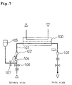
- a replenisher solution (normally, a physiological saline is used) is injected into the body of a patient when the blood pressure of the patient is lowered during blood dialysis treatment, and in infusing the replenisher solution, conventionally, there are adopted methods, for example, as illustrated in Fig. 7 and Fig. 8.
- a replenisher solution supply source 105 is connected to a blood circulation path 101 and the replenisher solution is infused while stopping the blood dialysis operation.
- the replenisher solution supply source 105 a bottle or a bag filled with sterilized replenisher solution is generally adopted.
- a valve 106 is closed, a valve 107 is opened and the replenisher solution is infused from the replenisher solution supply source 105 into the blood circulation path 101 by a blood pump 104.
- Flow rate of the replenisher solution is determined by the blood pump 104.
- numeral 100 designates a dialyzer and numerals 102 and 103 designate drip chambers.
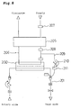
- a replenisher solution line 209 is separately provided and a dialysate in a dialysate circulation path 206 which is cleaned by endotoxin filters 207 and 208 is infused into a blood circulation path 201.
- the replenisher solution line 209 is provided with an endotoxin filter 211 for further cleaning the dialysate and the replenisher solution is infused by a replenisher solution pump 210.
- numeral 200 designates a dialyzer and numeral 205 designates a closed type water-removal control apparatus.
- the setup operation of connecting the replenisher solution supply source to the blood line and adding the replenisher solution (the case of a large amount of the replenisher solution) requires additional labor, and there are drawbacks in that there is a danger of erroneous operation or contamination since the replenishing operation is comparatively troublesome and that the cost is considerable.
- the dialysate is infused directly into the blood circulation path and accordingly, two of the endotoxin filters are normally needed and the cost is increased. Further, although the solution needs to be replenished when the blood pressure is lowered, according to the system of Fig. 8, water is removed by the dialyzer by a volume of the replenished solution and accordingly, there is a drawback in that the solution cannot be substantially replenished.
- the invention has been carried out in view of the above-described situation and it is an object thereof to provide a dialysis system which does not need to use physiological saline in replenishing a solution or in cleaning and priming the dialysis system, does not need a troublesome setup operation and replenishing of the solution can easily and accurately be set with the flow rate of a replenished solution.
- the inventors have conceived of a system in which a pump for infusing a dialysate is provided in a communication line of the dialysate and the dialysate is pressurized into a closed communication line of the dialysate and by which the dialysate is infused from a side of a dialysate chamber to a side of a blood chamber of a dialyzer, and completed the invention.
- a method of cleaning and priming a dialysis system which includes a closed type water-removal control apparatus, a dialysate line, a dialyzer and a blood line wherein a dialysate is made to flow into a blood circulation path through a membrane of the dialyzer by pressurizing the dialysate from a dialysate source into a closed communication line of the dialysate.
- the dialysis system is a dialysis system for central dialysate (i.e., multiple persons) supply.
- a dialysis system comprising a dialyzer having a dialysate flow path and a blood flow path partitioned by a dialysis membrane, a closed-type water-removal control apparatus for controlling a difference between volumes of a fresh dialysate flowing into the dialyzer and a used dialysate flowing out of the dialyzer by removing a volume of water, a dialysate line connecting the closed-type water-removal control apparatus and the dialysate flow path of the dialyzer, a dialysate pressurizing line branched between a dialysate source and the closed type water-removal control apparatus and connected to a communication line of the dialysate, a dialysate pressurizing pump provided in the dialysate pressurizing line, an artery side blood line connected to a blood inlet of the dialyzer, a blood pump provided in the artery side blood line and a vein side blood line connected to a blood outlet of
- the dialysis system is a dialysis system for central dialysate supply.
- the dialysate pressurizing pump is controlled by pressure of the dialysate and/or pressure of vein.
- the dialysate pressurizing pump can also be set with a flow rate and a volume of pressurizing the dialysate.
- An endotoxin filter can be provided in a dialysate line between the dialysate pressurizing line and the dialyzer.
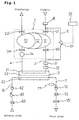
- a dialysis system includes a dialyzer 2, a closed type water-removal control apparatus 1 for controlling a difference between volumes of a fresh dialysate flowing into the dialyzer 2 and a used dialysate flowing out of the dialyzer 2 according to a water-removal amount, a fresh dialysate line 3 as well as a used dialysate line 4, a dialysate pressurizing line 5, a dialysate pressurizing pump 51 installed in the dialysate pressurizing line 5, an artery side blood line 6, a blood pump 61 installed in the artery side blood line 6 and a vein side blood line 7.
- the dialysate is pressurized from the dialysate pressurizing line 5 into a communication line of the dialysate which includes the closed-type water-removal control apparatus 1, the fresh dialysate line 3 and the used dialysate line 4, by means of which the dialysate is made to flow from a dialysate flow path 21 into a blood flow path 22 through a dialysis membrane 23 of the dialyzer 2 to thereby clean and prime an inside of a blood circulation path including the blood flow path 22 and the blood lines 6 and 7.
- the dialysate pressurizing line 5 is connected to the fresh dialysate line 3 and the fresh dialysate line 3 is installed with an endotoxin filter 31 preferably downstream from a portion thereof connected with the dialysate pressurizing line 5.
- numeral 8 designates an endotoxin filter
- numeral 14 designates a solution pressurizing pump
- numeral 32 designates a dialysate line pressure sensor
- numeral 52 designates a control apparatus
- numerals 62 and 72 designate drip chambers
- numerals 63 and 73 designate air bubble sensors
- numeral 71 designates a blood line pressure sensor and notations V1, V2, V3, V4 and V5 designate opening and closing valves.
- Fig. 1 illustrates an apparatus similar to disclosed in by Japanese Patent Publication No. 54590/1991.
- the apparatus is provided with a constant volume chamber partitioned into a fresh dialysate chamber 11 and a used dialysate chamber 13 by a flexible partition wall 12 filled with silicone oil, and when an opening and closing valve V1 is opened, dialysate from a dialysate source (not illustrated) is filled in the fresh dialysate chamber 11.
- the dialyzer 2 is provided with the dialysate flow path 21 and the blood flow path 22 partitioned by the dialysis membrane 23 and an inlet and an outlet of the dialysate flow path 21 of the dialyzer 2 are connected to the fresh dialysate chamber 11 and the used dialysate chamber 13 of the closed type water-removal control apparatus 1 respectively through the fresh dialysate line 3 and the used dialysate line 4.
- an inlet and an outlet of the blood flow path 22 of the dialyzer 2 are respectively connected with the artery side blood line 6 and the vein side blood line 7.
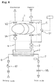
- the dialysate pressurizing pump 51 and the blood pump 61 are operated in directions of arrow marks A and B. Then, a fresh dialysate from a dialysate source is supplied to the dialysate flow path 21 of the dialyzer 2 via the dialysate pressurizing line 5 and the endotoxin filter 31 by the dialysate pressurizing pump 51, flows to the side of the blood flow path 22 by permeating the dialysis membrane 23 in the dialyzer 2 and is discharged to the outside via the artery side blood line 6. The inside of the blood circulation path on the artery side is cleaned and primed during this procedure.
- the fresh dialysate supplied to the dialysate flow path 21 of the dialyzer 2 similarly flows to the side of the blood flow path 22 and is discharged to the outside via the vein side blood line 7 in this case.
- the inside of the blood circulation path on the vein side is cleaned and primed during this procedure.
- the dialysate pressurizing pump 51 is stopped, the cleaning solution in the blood circulation path is substituted by a heparinized physiological saline (however, a line for supplying the physiological saline needs to be installed separately), as necessary and thereafter the opening and closing valve V5 is closed (refer to Fig. 6) and the blood lines 6 and 7 are connected to the vein of a patient for which the dialysis treatment has been prepared.
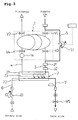
- the dialysate from the dialysate source is fills the fresh dialysate chamber 11 of the closed-type water-removal control apparatus 1 via the endotoxin filter 8.
- the opening and closing valves V1 and V2 are closed, the opening and closing valves V3 and V4 are opened (at this point, the communication line of the dialysate becomes a closed line), a solution pressurizing pump 14 is operated, and the blood pump 61 is operated in a direction of an arrow mark C.
- the fresh dialysate is supplied from the fresh dialysate chamber 11 to the dialysate flow path 21 of the dialyzer 2 via the fresh dialysate line 3 and the blood of the patient is delivered to the blood flow path 22 by passing though the artery side blood line 6 by the blood pump 61.
- the blood is dialyzed in the dialyzer through the dialysis membrane 23 and is returned to the patient via the vein side blood line 7.
- the used dialysate fills the used dialysate chamber 13 via the used dialysate line 4.
- the communication line of the dialysate becomes the closed line and, therefore, water can accurately be removed by discharging the silicone oil of the partition wall 12 from the chamber.
- the opening and closing valves V1 and V2 are opened and the opening and closing valves V3 and V4 are closed. Then, the dialysate from the dialysate source fills the fresh dialysate chamber 11 via the endotoxin filter 8 and the used dialysate having a volume equal to that of the fresh dialysate supplied to the fresh dialysate chamber 11, is discharged from the used dialysate chamber 13. Thereafter, a similar dialysis operation is repeated.
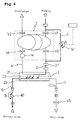
- the dialysate pressurizing pump 51 of the dialysate pressurizing line 5 is operated in the direction of the arrow mark A.
- the dialysate pressurizing line 5 is connected to the fresh dialysate line 3 or the used dialysate line 4 (not shown) and the fresh dialysate line 3 is preferably installed with the endotoxin filter 31.
- the fresh dialysate from the dialysate source is delivered to the fresh dialysate line 3 via the dialysate pressurizing line 5 by the dialysate pressurizing pump 51 and is supplied to the dialysate flow path 21 of the dialyzer 2 via the endotoxin filter 31 and the solution pressure sensor 32.
- the fresh dialysate exceeding the volume of the constant volume chamber permeates the dialysis membrane 23 of the dialyzer 2 and flows from the dialysate flow path 21 to the blood flow path 22, and is supplied into the body of the patient via the vein side blood line 7.
- the recovery of the blood can be carried out by a method quite similar to the method of cleaning and priming. That is, the opening and closing valves V3, V4 and V5 are closed, as illustrated in Fig. 4, the dialysate pressurizing pump 51 and the blood pump 61 are operated in the directions of the arrow marks A and B, then, the fresh dialysate flows into the blood circulation path at the artery side and the blood in the artery side blood circulation path is returned into the body of the patient. Next, as illustrated in Fig. 5, the blood pump 61 is stopped and the opening and closing valve V5 is opened. Then, in this case, the fresh dialysate flows into the blood circulation path on the vein side and blood in the vein side blood circulation path is returned into the body of the patient. When the recovery operation of blood in the blood circulation path has been finished, as illustrated in Fig. 6, the dialysate pressurizing pump 51 is stopped, the opening and closing valve V5 is closed and the blood lines 6 and 7 are detached from the vein of the patient.
- the blood solution pressurizing pump 51 can be controlled by dialysate line pressure detected by the solution pressure sensor 32 (in the drawing, fresh dialysate pressure is detected) or can be controlled by blood line pressure detected by the line pressure sensor 71 (in the drawing, vein pressure is detected) or can be controlled by both of the dialysate line pressure and the blood line pressure as necessary. Further, it is preferable that the dialysate pressurizing pump 51 is set with a flow speed or a dialysate pressurizing amount. Further, air bubble sensor 63 can be installed in the artery side blood line 6 to confirm finishing of the artery side cleaning and priming.
- fresh dialysate from a dialysate source can be used as a replenisher solution, as a solution for blood recovery and as a cleaning and priming solution and accordingly, there is no need of conducting a troublesome setup operation which is conventially out in replenishing the solution, cleaning and priming the blood line and recovering blood and labor of persons engaged in medical treatment can be considerably reduced. Further, the flow rate of the replenishing solution can be set easily and accurately. Further, the use of sterilized physiological saline in recovering blood is dispensed with and, therefore, the cost of dialysis treatment can be significantly reduced.
Abstract
Description
- The present invention relates to a dialysis system and a method of cleaning and priming a blood circulation path of the dialysis system. More particularly, the invention relates to a dialysis system capable of using a dialysate in place of physiological saline as a replenisher solution when blood pressure is lowered and capable of using a dialysate in place of physiological saline in a cleaning and priming operation and in a blood returning operation in blood dialysis treatment, and relates to a method of cleaning and priming of dialysis system.
- A dialysate is used in blood dialysis. Air or filled sterilized water is contained in a dialyzer before the dialyzer is used in blood dialysis and so the air or the sterilized water needs to be removed. Therefore, as a pretreatment, conventionally, the inside of a dialyzer and the inside of a blood line connected to the dialyzer (hereinafter, referred to as the inside of a blood circulation path) are cleaned and primed by using, for example, physiological saline (normally, about 500 through 1000 ml).
- Further, after finishing blood dialysis, blood remaining in the inside of the blood circulation path needs to be returned into the body of a patient who has undergone the blood dialysis treatment (referred to as blood returning) as much as possible, and as a post treatment, conventionally, blood is returned into the human body by using, for example, physiological saline (about 300 ml).
- However, since physiological saline is expensive, a conventional blood dialysis system using a large amount thereof is problematic because of the considerable cost of the blood dialysis.
- Hence, in order to resolve such a drawback, there have been proposed a method and an apparatus of blood dialysis (Japanese Unexamined Patent Publication No. 80346/1996) capable of achieving a reduction in the cost of the blood dialysis by reducing the volume of physiological saline used in the priming and blood returning operations, and a physical solution treating apparatus (Japanese Unexamined Patent Publication No. 150201/1996) capable of using a dialysate in place of a physiological saline used in the priming and blood returning operations.
- According to the blood dialysis system of Japanese Unexamined Patent Publication No. 80346/1996, when a blood dialysis operation is stopped, a dialysate from dialysate supply source is filtered to clean the dialysate and the provided filtered dialysate is pressurized from a dialysate flow path of a dialyzer to a blood flow path through dialysis membranes constituting a dialysis element. However, according to the method, in respect of blood remaining in a blood circulation path upstream from the blood flow path, the blood needs to be pushed out to the blood flow path by using physiological saline. Thus, despite the improvement, there is a drawback in that a necessary amount of physiological saline needs to be prepared and the operation takes time and labor.
- Meanwhile, according to the physical solution treating apparatus of Japanese Unexamined Patent Publication No. 150201/1996, a dialysate reservoir bag is connected to intermediate point of an artery side line through a branch tube and dialysate in the dialysate reservoir bag can be transferred to prime a blood chamber and a vein side line through the artery side line. However, according to the method, there are drawbacks in that not only is the dialysate reservoir bag expensive but also an operation of filling the dialysate into the bag becomes necessary and the operation is troublesome.
- Further, there is a case in which a replenisher solution (normally, a physiological saline is used) is injected into the body of a patient when the blood pressure of the patient is lowered during blood dialysis treatment, and in infusing the replenisher solution, conventionally, there are adopted methods, for example, as illustrated in Fig. 7 and Fig. 8.
- According to the method illustrated in Fig. 7, a replenisher
solution supply source 105 is connected to ablood circulation path 101 and the replenisher solution is infused while stopping the blood dialysis operation. As the replenishersolution supply source 105, a bottle or a bag filled with sterilized replenisher solution is generally adopted. In replenishing the solution, avalve 106 is closed, avalve 107 is opened and the replenisher solution is infused from the replenishersolution supply source 105 into theblood circulation path 101 by ablood pump 104. Flow rate of the replenisher solution is determined by theblood pump 104. Further, in the drawing,numeral 100 designates a dialyzer andnumerals 102 and 103 designate drip chambers. - According to the method illusstrated in Fig. 8, a
replenisher solution line 209 is separately provided and a dialysate in adialysate circulation path 206 which is cleaned byendotoxin filters blood circulation path 201. Thereplenisher solution line 209 is provided with anendotoxin filter 211 for further cleaning the dialysate and the replenisher solution is infused by areplenisher solution pump 210. Further, in the drawing,numeral 200 designates a dialyzer andnumeral 205 designates a closed type water-removal control apparatus. - However, according to the method illustrated in Fig. 7, the replenisher solution needs to be prepared, the setup operation of connecting the replenisher solution supply source to the blood line and adding the replenisher solution (the case of a large amount of the replenisher solution) requires additional labor, and there are drawbacks in that there is a danger of erroneous operation or contamination since the replenishing operation is comparatively troublesome and that the cost is considerable.
- Meanwhile, according to the method illustrated in Fig. 8, the dialysate is infused directly into the blood circulation path and accordingly, two of the endotoxin filters are normally needed and the cost is increased. Further, although the solution needs to be replenished when the blood pressure is lowered, according to the system of Fig. 8, water is removed by the dialyzer by a volume of the replenished solution and accordingly, there is a drawback in that the solution cannot be substantially replenished.
- The invention has been carried out in view of the above-described situation and it is an object thereof to provide a dialysis system which does not need to use physiological saline in replenishing a solution or in cleaning and priming the dialysis system, does not need a troublesome setup operation and replenishing of the solution can easily and accurately be set with the flow rate of a replenished solution.
- As a result of intensive study in view of the above-described situation, the inventors have conceived of a system in which a pump for infusing a dialysate is provided in a communication line of the dialysate and the dialysate is pressurized into a closed communication line of the dialysate and by which the dialysate is infused from a side of a dialysate chamber to a side of a blood chamber of a dialyzer, and completed the invention. That is, according to an aspect of the invention, there is provided a method of cleaning and priming a dialysis system which includes a closed type water-removal control apparatus, a dialysate line, a dialyzer and a blood line wherein a dialysate is made to flow into a blood circulation path through a membrane of the dialyzer by pressurizing the dialysate from a dialysate source into a closed communication line of the dialysate. In this case, it is preferable that the dialysis system is a dialysis system for central dialysate (i.e., multiple persons) supply.
- Further, according to another aspect of the invention, there is provided a dialysis system comprising a dialyzer having a dialysate flow path and a blood flow path partitioned by a dialysis membrane, a closed-type water-removal control apparatus for controlling a difference between volumes of a fresh dialysate flowing into the dialyzer and a used dialysate flowing out of the dialyzer by removing a volume of water, a dialysate line connecting the closed-type water-removal control apparatus and the dialysate flow path of the dialyzer, a dialysate pressurizing line branched between a dialysate source and the closed type water-removal control apparatus and connected to a communication line of the dialysate, a dialysate pressurizing pump provided in the dialysate pressurizing line, an artery side blood line connected to a blood inlet of the dialyzer, a blood pump provided in the artery side blood line and a vein side blood line connected to a blood outlet of the dialyzer. In this case, it is preferable that the dialysis system is a dialysis system for central dialysate supply. Further, it is preferable that the dialysate pressurizing pump is controlled by pressure of the dialysate and/or pressure of vein. The dialysate pressurizing pump can also be set with a flow rate and a volume of pressurizing the dialysate. An endotoxin filter can be provided in a dialysate line between the dialysate pressurizing line and the dialyzer.
-
- Fig. 1 is an outline constitution view of an embodiment of the invention;
- Fig. 2 is an explanatory view illustrating a state of carrying out a dialysis treatment in the system of Fig. 1;
- Fig. 3 is an explanatory view illustrating a solution replenishing operation under a dialysis treatment in the system of Fig. 1;
- Fig. 4 is an explanatory view illustrating a cleaning and priming operation of an artery side of a blood circulation path in the system of Fig. 1;
- Fig. 5 is an explanatory view illustrating the cleaning and priming operation of a vein side of the blood circulation path in the system of Fig. 1;
- Fig. 6 is an explanatory view illustrating a state of finishing the cleaning and priming operation in the system of Fig. 1;
- Fig. 7 is an explanatory view of a conventional solution replenishing method; and
- Fig. 8 is an explanatory view of another conventional solution replenishing method.
-
- An explanation will be given of embodiments of the invention with reference to the drawings as follows.
- As illustrated in Fig. 1, a dialysis system according to the invention includes a
dialyzer 2, a closed type water-removal control apparatus 1 for controlling a difference between volumes of a fresh dialysate flowing into thedialyzer 2 and a used dialysate flowing out of thedialyzer 2 according to a water-removal amount, afresh dialysate line 3 as well as a useddialysate line 4, adialysate pressurizing line 5, adialysate pressurizing pump 51 installed in the dialysate pressurizingline 5, an arteryside blood line 6, ablood pump 61 installed in the arteryside blood line 6 and a veinside blood line 7. According to the dialysis system, the dialysate is pressurized from the dialysate pressurizingline 5 into a communication line of the dialysate which includes the closed-type water-removal control apparatus 1, thefresh dialysate line 3 and the useddialysate line 4, by means of which the dialysate is made to flow from adialysate flow path 21 into ablood flow path 22 through adialysis membrane 23 of thedialyzer 2 to thereby clean and prime an inside of a blood circulation path including theblood flow path 22 and theblood lines - Further, according to Fig. 1, the dialysate
pressurizing line 5 is connected to thefresh dialysate line 3 and thefresh dialysate line 3 is installed with anendotoxin filter 31 preferably downstream from a portion thereof connected with thedialysate pressurizing line 5. Further, in the drawing,numeral 8 designates an endotoxin filter,numeral 14 designates a solution pressurizing pump,numeral 32 designates a dialysate line pressure sensor,numeral 52 designates a control apparatus,numerals numerals 63 and 73 designate air bubble sensors,numeral 71 designates a blood line pressure sensor and notations V1, V2, V3, V4 and V5 designate opening and closing valves. - As the closed-type water-removal control apparatus 1, there is adopted an apparatus disclosed in, for example, Japanese Patent Publication No. 82/1981 (U.S. Patent No.4,676,905), Japanese Unexamined Patent Publication No. 66761/1982 or Japanese Patent Publication No. 54590/1991 (U.S. Patent No.4,935,125), the disclosure of each of which is incorporated herein by reference. Fig. 1 illustrates an apparatus similar to disclosed in by Japanese Patent Publication No. 54590/1991. The apparatus is provided with a constant volume chamber partitioned into a
fresh dialysate chamber 11 and a useddialysate chamber 13 by aflexible partition wall 12 filled with silicone oil, and when an opening and closing valve V1 is opened, dialysate from a dialysate source (not illustrated) is filled in thefresh dialysate chamber 11. Further, thedialyzer 2 is provided with thedialysate flow path 21 and theblood flow path 22 partitioned by thedialysis membrane 23 and an inlet and an outlet of thedialysate flow path 21 of thedialyzer 2 are connected to thefresh dialysate chamber 11 and the useddialysate chamber 13 of the closed type water-removal control apparatus 1 respectively through thefresh dialysate line 3 and the useddialysate line 4. Further, an inlet and an outlet of theblood flow path 22 of thedialyzer 2 are respectively connected with the arteryside blood line 6 and the veinside blood line 7. - In a dialysis treatment, first, the inside of the blood circulation path including the
dialyzer 2, the arteryside blood line 6 and the veinside blood line 7 needs to be cleaned and primed. - In a state of closing the opening and closing valves V1, V2, V3, V4 and V5, illustrated in Fig. 4, the
dialysate pressurizing pump 51 and theblood pump 61 are operated in directions of arrow marks A and B. Then, a fresh dialysate from a dialysate source is supplied to thedialysate flow path 21 of thedialyzer 2 via the dialysate pressurizingline 5 and theendotoxin filter 31 by thedialysate pressurizing pump 51, flows to the side of theblood flow path 22 by permeating thedialysis membrane 23 in thedialyzer 2 and is discharged to the outside via the arteryside blood line 6. The inside of the blood circulation path on the artery side is cleaned and primed during this procedure. Next, as illustrated in Fig. 5, when theblood pump 61 is stopped and the opening and closing valve V5 is opened, the fresh dialysate supplied to thedialysate flow path 21 of thedialyzer 2 similarly flows to the side of theblood flow path 22 and is discharged to the outside via the veinside blood line 7 in this case. The inside of the blood circulation path on the vein side is cleaned and primed during this procedure. When the cleaning and priming operation in the blood circulation path is finished, thedialysate pressurizing pump 51 is stopped, the cleaning solution in the blood circulation path is substituted by a heparinized physiological saline (however, a line for supplying the physiological saline needs to be installed separately), as necessary and thereafter the opening and closing valve V5 is closed (refer to Fig. 6) and theblood lines - First, when the opening and closing valves V1 and V2 are opened, the dialysate from the dialysate source is fills the
fresh dialysate chamber 11 of the closed-type water-removal control apparatus 1 via theendotoxin filter 8. When thefresh dialysate chamber 11 becomes full with the dialysate from the dialysate source, as illustrated in Fig. 2, the opening and closing valves V1 and V2 are closed, the opening and closing valves V3 and V4 are opened (at this point, the communication line of the dialysate becomes a closed line), asolution pressurizing pump 14 is operated, and theblood pump 61 is operated in a direction of an arrow mark C. Then, the fresh dialysate is supplied from thefresh dialysate chamber 11 to thedialysate flow path 21 of thedialyzer 2 via thefresh dialysate line 3 and the blood of the patient is delivered to theblood flow path 22 by passing though the arteryside blood line 6 by theblood pump 61. The blood is dialyzed in the dialyzer through thedialysis membrane 23 and is returned to the patient via the veinside blood line 7. Meanwhile, the used dialysate fills the useddialysate chamber 13 via the useddialysate line 4. In this case, the communication line of the dialysate becomes the closed line and, therefore, water can accurately be removed by discharging the silicone oil of thepartition wall 12 from the chamber. When the useddialysate chamber 13 becomes full with the used dialysate, the opening and closing valves V1 and V2 are opened and the opening and closing valves V3 and V4 are closed. Then, the dialysate from the dialysate source fills thefresh dialysate chamber 11 via theendotoxin filter 8 and the used dialysate having a volume equal to that of the fresh dialysate supplied to thefresh dialysate chamber 11, is discharged from the useddialysate chamber 13. Thereafter, a similar dialysis operation is repeated. - There is a case in which the solution needs to be replenished when the blood pressure of the patient is lowered in the dialysis treatment.
- In that case, as illustrated in Fig. 3, the
dialysate pressurizing pump 51 of thedialysate pressurizing line 5 is operated in the direction of the arrow mark A. Thedialysate pressurizing line 5 is connected to thefresh dialysate line 3 or the used dialysate line 4 (not shown) and thefresh dialysate line 3 is preferably installed with theendotoxin filter 31. The fresh dialysate from the dialysate source is delivered to thefresh dialysate line 3 via thedialysate pressurizing line 5 by thedialysate pressurizing pump 51 and is supplied to thedialysate flow path 21 of thedialyzer 2 via theendotoxin filter 31 and thesolution pressure sensor 32. Then, since the communication line of the dialysate becomes a closed line, the fresh dialysate exceeding the volume of the constant volume chamber permeates thedialysis membrane 23 of thedialyzer 2 and flows from thedialysate flow path 21 to theblood flow path 22, and is supplied into the body of the patient via the veinside blood line 7. - When the dialysis treatment is finished, blood remaining in the blood circulation path needs to be returned into the body (vein) of the patient (referred to as recovery of blood).
- The recovery of the blood can be carried out by a method quite similar to the method of cleaning and priming. That is, the opening and closing valves V3, V4 and V5 are closed, as illustrated in Fig. 4, the
dialysate pressurizing pump 51 and theblood pump 61 are operated in the directions of the arrow marks A and B, then, the fresh dialysate flows into the blood circulation path at the artery side and the blood in the artery side blood circulation path is returned into the body of the patient. Next, as illustrated in Fig. 5, theblood pump 61 is stopped and the opening and closing valve V5 is opened. Then, in this case, the fresh dialysate flows into the blood circulation path on the vein side and blood in the vein side blood circulation path is returned into the body of the patient. When the recovery operation of blood in the blood circulation path has been finished, as illustrated in Fig. 6, thedialysate pressurizing pump 51 is stopped, the opening and closing valve V5 is closed and theblood lines - Further, the blood
solution pressurizing pump 51 can be controlled by dialysate line pressure detected by the solution pressure sensor 32 (in the drawing, fresh dialysate pressure is detected) or can be controlled by blood line pressure detected by the line pressure sensor 71 (in the drawing, vein pressure is detected) or can be controlled by both of the dialysate line pressure and the blood line pressure as necessary. Further, it is preferable that thedialysate pressurizing pump 51 is set with a flow speed or a dialysate pressurizing amount. Further,air bubble sensor 63 can be installed in the arteryside blood line 6 to confirm finishing of the artery side cleaning and priming. - As is apparent from the above description, according to the invention, fresh dialysate from a dialysate source can be used as a replenisher solution, as a solution for blood recovery and as a cleaning and priming solution and accordingly, there is no need of conducting a troublesome setup operation which is conventially out in replenishing the solution, cleaning and priming the blood line and recovering blood and labor of persons engaged in medical treatment can be considerably reduced. Further, the flow rate of the replenishing solution can be set easily and accurately. Further, the use of sterilized physiological saline in recovering blood is dispensed with and, therefore, the cost of dialysis treatment can be significantly reduced.
Claims (7)
- A method of cleaning and priming a dialysis system comprising a closed type water-removal control apparatus, a dialysate line, a dialyzer and a blood line:
wherein a dialysate is made to flow into a blood circulation path through a membrane of the dialyzer by pressuring the dialysate from a dialysate source into a closed communication line of the dialysate. - The cleaning and priming method of a dialysis system according to Claim 1:
wherein the dialysis system is a dialysis system for a central dialysate supply. - A dialysis system comprising:a dialyzer having a dialysate flow path and a blood flow path partitioned by a dialysis membrane;a closed type water-removal control apparatus for controlling a difference between volumes of a fresh dialysate flowing into the dialyzer and a used dialysate flowing out of the dialyzer by removing a volume of water;a dialysate lines connecting the closed-type water-removal control apparatus and the dialysate flow path of the dialyzer;a dialysate pressurizing line branched between a dialysate source and the closed-type water-removal control apparatus and connected to a communication line of the dialysate;a dialysate pressurizing pump provided in the dialysate pressurizing line;an artery side blood line connected to a blood inlet of the dialyzer;a blood pump provided in the artery side blood line; anda vein side blood line connected to a blood outlet of the dialyzer.
- The dialysis system according to Claim 1:
wherein the dialysis system is a dialysis system for a central dialysate supply. - The dialysis system according to Claim 3 or 4:
wherein the dialysate pressurizing pump is controlled by dialysate line pressure and/or blood line pressure. - The dialysis system according to any one of Claims 3 through 5:
wherein the dialysate pressurizing pump is set with a flow rate and a volume of pressurizing the dialysate. - The dialysis system according to any one of Claims 3 through 6:
wherein an endotoxin filter is provided in the dialysate line between the dialysate pressurizing pump and the dialyzer.
Applications Claiming Priority (2)
| Application Number | Priority Date | Filing Date | Title |
|---|---|---|---|
| JP10285711A JP2000107283A (en) | 1998-10-07 | 1998-10-07 | Dialysis apparatus and washing priming method |
| JP28571198 | 1998-10-07 |
Publications (3)
| Publication Number | Publication Date |
|---|---|
| EP0992255A2 true EP0992255A2 (en) | 2000-04-12 |
| EP0992255A3 EP0992255A3 (en) | 2000-10-11 |
| EP0992255B1 EP0992255B1 (en) | 2005-12-14 |
Family
ID=17695049
Family Applications (1)
| Application Number | Title | Priority Date | Filing Date |
|---|---|---|---|
| EP99119162A Expired - Lifetime EP0992255B1 (en) | 1998-10-07 | 1999-10-06 | Dialysis system and cleaning and priming method thereof |
Country Status (4)
| Country | Link |
|---|---|
| US (2) | US6277272B1 (en) |
| EP (1) | EP0992255B1 (en) |
| JP (1) | JP2000107283A (en) |
| DE (1) | DE69928887T2 (en) |
Cited By (28)
| Publication number | Priority date | Publication date | Assignee | Title |
|---|---|---|---|---|
| WO2002098491A1 (en) * | 2001-06-05 | 2002-12-12 | Gambro Lundia Ab | Method for filling and washing a filter for a dialysis machine |
| EP1295617A1 (en) * | 2000-06-15 | 2003-03-26 | JMS Co., Ltd. | Automatic dialyzer and dialyzing method |
| EP1655044A3 (en) * | 2004-11-05 | 2006-11-02 | Nipro Corporation | Blood purification apparatus |
| WO2010027435A1 (en) | 2007-02-27 | 2010-03-11 | Deka Products Limited Partnership | Hemodialysis systems, cassettes and methods |
| US7794141B2 (en) | 2006-04-14 | 2010-09-14 | Deka Products Limited Partnership | Thermal and coductivity sensing systems, devices and methods |
| US7967022B2 (en) | 2007-02-27 | 2011-06-28 | Deka Products Limited Partnership | Cassette system integrated apparatus |
| US8042563B2 (en) | 2007-02-27 | 2011-10-25 | Deka Products Limited Partnership | Cassette system integrated apparatus |
| US8197439B2 (en) | 2008-01-23 | 2012-06-12 | Deka Products Limited Partnership | Fluid volume determination for medical treatment system |
| US8246826B2 (en) | 2007-02-27 | 2012-08-21 | Deka Products Limited Partnership | Hemodialysis systems and methods |
| US8366316B2 (en) | 2006-04-14 | 2013-02-05 | Deka Products Limited Partnership | Sensor apparatus systems, devices and methods |
| US8393690B2 (en) | 2007-02-27 | 2013-03-12 | Deka Products Limited Partnership | Enclosure for a portable hemodialysis system |
| US8409441B2 (en) | 2007-02-27 | 2013-04-02 | Deka Products Limited Partnership | Blood treatment systems and methods |
| US8425471B2 (en) | 2007-02-27 | 2013-04-23 | Deka Products Limited Partnership | Reagent supply for a hemodialysis system |
| EP2583702A1 (en) * | 2011-10-20 | 2013-04-24 | D_MED Consulting AG | Method for ending haemodialysis |
| US8491184B2 (en) | 2007-02-27 | 2013-07-23 | Deka Products Limited Partnership | Sensor apparatus systems, devices and methods |
| US8562834B2 (en) | 2007-02-27 | 2013-10-22 | Deka Products Limited Partnership | Modular assembly for a portable hemodialysis system |
| US8708950B2 (en) | 2010-07-07 | 2014-04-29 | Deka Products Limited Partnership | Medical treatment system and methods using a plurality of fluid lines |
| US8771508B2 (en) | 2008-08-27 | 2014-07-08 | Deka Products Limited Partnership | Dialyzer cartridge mounting arrangement for a hemodialysis system |
| US9028691B2 (en) | 2007-02-27 | 2015-05-12 | Deka Products Limited Partnership | Blood circuit assembly for a hemodialysis system |
| US9078971B2 (en) | 2008-01-23 | 2015-07-14 | Deka Products Limited Partnership | Medical treatment system and methods using a plurality of fluid lines |
| EP1450879B2 (en) † | 2001-11-23 | 2015-12-30 | Gambro Lundia AB | Method of priming a dialysis machine |
| US9517295B2 (en) | 2007-02-27 | 2016-12-13 | Deka Products Limited Partnership | Blood treatment systems and methods |
| US9597442B2 (en) | 2007-02-27 | 2017-03-21 | Deka Products Limited Partnership | Air trap for a medical infusion device |
| US9724458B2 (en) | 2011-05-24 | 2017-08-08 | Deka Products Limited Partnership | Hemodialysis system |
| US9861732B2 (en) | 2011-11-04 | 2018-01-09 | Deka Products Limited Partnership | Medical treatment system and methods using a plurality of fluid lines |
| US10201650B2 (en) | 2009-10-30 | 2019-02-12 | Deka Products Limited Partnership | Apparatus and method for detecting disconnection of an intravascular access device |
| AU2013364131B2 (en) * | 2012-12-21 | 2019-07-04 | Deka Products Limited Partnership | System, method, and apparatus for electronic patient care |
| US10537671B2 (en) | 2006-04-14 | 2020-01-21 | Deka Products Limited Partnership | Automated control mechanisms in a hemodialysis apparatus |
Families Citing this family (48)
| Publication number | Priority date | Publication date | Assignee | Title |
|---|---|---|---|---|
| JP3941092B2 (en) * | 2000-07-14 | 2007-07-04 | ニプロ株式会社 | Dialysis machine with dialysate preparation mechanism |
| JP4000584B2 (en) * | 2000-07-14 | 2007-10-31 | ニプロ株式会社 | Dialysate preparation device |
| JP3719375B2 (en) * | 2000-07-26 | 2005-11-24 | ニプロ株式会社 | Solution preparation equipment |
| JP4457235B2 (en) * | 2001-12-18 | 2010-04-28 | 株式会社北九州バイオフィジックス研究所 | Automatic hemodialysis apparatus and priming method using the apparatus. |
| US7544179B2 (en) | 2002-04-11 | 2009-06-09 | Deka Products Limited Partnership | System and method for delivering a target volume of fluid |
| US8038639B2 (en) | 2004-11-04 | 2011-10-18 | Baxter International Inc. | Medical fluid system with flexible sheeting disposable unit |
| US8029454B2 (en) | 2003-11-05 | 2011-10-04 | Baxter International Inc. | High convection home hemodialysis/hemofiltration and sorbent system |
| CN1327913C (en) * | 2004-04-23 | 2007-07-25 | 暨南大学 | Method and apparatus for dialysate preparation and supply |
| JP2006006433A (en) * | 2004-06-23 | 2006-01-12 | Toray Medical Co Ltd | Method and device for autotransfusion of hemodialyzer |
| JP2008512195A (en) * | 2004-09-07 | 2008-04-24 | マイクロメツド・カーデイオバスキユラー・インコーポレイテツド | Method and system for physiological control of a blood pump |
| ES2356669T3 (en) * | 2005-09-15 | 2011-04-12 | Gambro Lundia Ab | PROCEDURE AND APPLIANCE FOR FILLING AND / OR RINING AN EXTRACORPOROUS BLOOD CIRCUIT. |
| US10463774B2 (en) | 2007-02-27 | 2019-11-05 | Deka Products Limited Partnership | Control systems and methods for blood or fluid handling medical devices |
| US8764702B2 (en) * | 2007-07-05 | 2014-07-01 | Baxter International Inc. | Dialysis system having dual patient line connection and prime |
| US8240636B2 (en) | 2009-01-12 | 2012-08-14 | Fresenius Medical Care Holdings, Inc. | Valve system |
| US8105487B2 (en) * | 2007-09-25 | 2012-01-31 | Fresenius Medical Care Holdings, Inc. | Manifolds for use in conducting dialysis |
| US20090101577A1 (en) * | 2007-09-28 | 2009-04-23 | Fulkerson Barry N | Methods and Systems for Controlling Ultrafiltration Using Central Venous Pressure Measurements |
| US9308307B2 (en) | 2007-09-13 | 2016-04-12 | Fresenius Medical Care Holdings, Inc. | Manifold diaphragms |
| US8535522B2 (en) * | 2009-02-12 | 2013-09-17 | Fresenius Medical Care Holdings, Inc. | System and method for detection of disconnection in an extracorporeal blood circuit |
| US20090114037A1 (en) * | 2007-10-11 | 2009-05-07 | Mark Forrest Smith | Photo-Acoustic Flow Meter |
| US9358331B2 (en) | 2007-09-13 | 2016-06-07 | Fresenius Medical Care Holdings, Inc. | Portable dialysis machine with improved reservoir heating system |
| US8040493B2 (en) * | 2007-10-11 | 2011-10-18 | Fresenius Medical Care Holdings, Inc. | Thermal flow meter |
| US8475399B2 (en) * | 2009-02-26 | 2013-07-02 | Fresenius Medical Care Holdings, Inc. | Methods and systems for measuring and verifying additives for use in a dialysis machine |
| US9199022B2 (en) | 2008-09-12 | 2015-12-01 | Fresenius Medical Care Holdings, Inc. | Modular reservoir assembly for a hemodialysis and hemofiltration system |
| US20090076434A1 (en) * | 2007-09-13 | 2009-03-19 | Mischelevich David J | Method and System for Achieving Volumetric Accuracy in Hemodialysis Systems |
| US8597505B2 (en) | 2007-09-13 | 2013-12-03 | Fresenius Medical Care Holdings, Inc. | Portable dialysis machine |
| US8444587B2 (en) | 2007-10-01 | 2013-05-21 | Baxter International Inc. | Fluid and air handling in blood and dialysis circuits |
| US8123947B2 (en) * | 2007-10-22 | 2012-02-28 | Baxter International Inc. | Priming and air removal systems and methods for dialysis |
| US8114276B2 (en) | 2007-10-24 | 2012-02-14 | Baxter International Inc. | Personal hemodialysis system |
| MX2010005907A (en) | 2007-11-29 | 2010-12-20 | Fresenius Med Care Hldg Inc | System and method for conducting hemodialysis and hemofiltration. |
| US10201647B2 (en) | 2008-01-23 | 2019-02-12 | Deka Products Limited Partnership | Medical treatment system and methods using a plurality of fluid lines |
| US10195330B2 (en) | 2008-01-23 | 2019-02-05 | Deka Products Limited Partnership | Medical treatment system and methods using a plurality of fluid lines |
| US20090294359A1 (en) * | 2008-06-03 | 2009-12-03 | Baxter International Inc. | Priming system and method using pumping and gravity |
| DE102008045422B4 (en) * | 2008-09-02 | 2017-10-12 | Fresenius Medical Care Deutschland Gmbh | Device for filling a filter and method for this purpose |
| US20100184198A1 (en) * | 2009-01-16 | 2010-07-22 | Joseph Russell T | Systems and Methods of Urea Processing to Reduce Sorbent Load |
| AU2009302327C1 (en) * | 2008-10-07 | 2015-09-10 | Fresenius Medical Care Holdings, Inc. | Priming system and method for dialysis systems |
| CA2739807C (en) | 2008-10-30 | 2017-02-28 | Fresenius Medical Care Holdings, Inc. | Modular, portable dialysis system |
| CN101564559B (en) * | 2009-05-15 | 2011-08-10 | 重庆山外山科技有限公司 | Volume-varied balancer for purifying blood |
| JP2011182992A (en) * | 2010-03-09 | 2011-09-22 | Kawasumi Lab Inc | Priming method and dialyzer of dialysis system |
| JP5560954B2 (en) * | 2010-06-25 | 2014-07-30 | ニプロ株式会社 | Blood return operation method and blood purification apparatus in blood purification apparatus |
| ES2445592T3 (en) | 2010-12-20 | 2014-03-04 | Gambro Lundia Ab | Method and system for providing priming and restitution fluids for extracorporeal blood treatment |
| US9999717B2 (en) | 2011-05-24 | 2018-06-19 | Deka Products Limited Partnership | Systems and methods for detecting vascular access disconnection |
| FR2980712B1 (en) | 2011-10-03 | 2013-10-04 | Physidia | DIALYSIS MACHINE COMPRISING MEANS FOR ULTRAFILTRATION AND RETROFILTRATION |
| US9201036B2 (en) | 2012-12-21 | 2015-12-01 | Fresenius Medical Care Holdings, Inc. | Method and system of monitoring electrolyte levels and composition using capacitance or induction |
| US9157786B2 (en) | 2012-12-24 | 2015-10-13 | Fresenius Medical Care Holdings, Inc. | Load suspension and weighing system for a dialysis machine reservoir |
| US9433720B2 (en) | 2013-03-14 | 2016-09-06 | Fresenius Medical Care Holdings, Inc. | Universal portable artificial kidney for hemodialysis and peritoneal dialysis |
| US20140263062A1 (en) | 2013-03-14 | 2014-09-18 | Fresenius Medical Care Holdings, Inc. | Universal portable machine for online hemodiafiltration using regenerated dialysate |
| US9354640B2 (en) * | 2013-11-11 | 2016-05-31 | Fresenius Medical Care Holdings, Inc. | Smart actuator for valve |
| US9486590B2 (en) | 2014-09-29 | 2016-11-08 | Fenwal, Inc. | Automatic purging of air from a fluid processing system |
Citations (4)
| Publication number | Priority date | Publication date | Assignee | Title |
|---|---|---|---|---|
| JPS5682B2 (en) | 1975-12-15 | 1981-01-06 | ||
| US4935125A (en) | 1987-09-01 | 1990-06-19 | Shibuya Kogyo Co., Ltd. | Dialysis system |
| JPH0880346A (en) | 1994-09-13 | 1996-03-26 | Toray Medical Kk | Blood dialyzing method and apparatus therefor |
| JPH08150201A (en) | 1994-11-30 | 1996-06-11 | Kawasumi Lab Inc | Body fluid treating device and priming method for body fluid treating device |
Family Cites Families (6)
| Publication number | Priority date | Publication date | Assignee | Title |
|---|---|---|---|---|
| US4495067A (en) * | 1980-12-02 | 1985-01-22 | Tracor, Inc. | Apparatus for preparation of infusion grade water |
| JP2979234B2 (en) | 1990-03-05 | 1999-11-15 | 旭メディカル株式会社 | Hemodialysis machine |
| US5336165A (en) * | 1991-08-21 | 1994-08-09 | Twardowski Zbylut J | Artificial kidney for frequent (daily) Hemodialysis |
| DE4208274C1 (en) * | 1992-03-13 | 1993-10-21 | Medical Support Gmbh | Method and arrangement for rinsing and filling the extracorporeal blood circuit of dialysis machines |
| US5591344A (en) * | 1995-02-13 | 1997-01-07 | Aksys, Ltd. | Hot water disinfection of dialysis machines, including the extracorporeal circuit thereof |
| US6331252B1 (en) * | 1998-07-31 | 2001-12-18 | Baxter International Inc. | Methods for priming a blood compartment of a hemodialyzer |
-
1998
- 1998-10-07 JP JP10285711A patent/JP2000107283A/en active Pending
-
1999
- 1999-10-06 EP EP99119162A patent/EP0992255B1/en not_active Expired - Lifetime
- 1999-10-06 DE DE69928887T patent/DE69928887T2/en not_active Expired - Lifetime
- 1999-10-07 US US09/413,817 patent/US6277272B1/en not_active Expired - Lifetime
-
2001
- 2001-06-25 US US09/886,986 patent/US6551513B2/en not_active Expired - Fee Related
Patent Citations (5)
| Publication number | Priority date | Publication date | Assignee | Title |
|---|---|---|---|---|
| JPS5682B2 (en) | 1975-12-15 | 1981-01-06 | ||
| US4676905A (en) | 1975-12-15 | 1987-06-30 | Toray Industries, Inc. | Fluid separation method and apparatus |
| US4935125A (en) | 1987-09-01 | 1990-06-19 | Shibuya Kogyo Co., Ltd. | Dialysis system |
| JPH0880346A (en) | 1994-09-13 | 1996-03-26 | Toray Medical Kk | Blood dialyzing method and apparatus therefor |
| JPH08150201A (en) | 1994-11-30 | 1996-06-11 | Kawasumi Lab Inc | Body fluid treating device and priming method for body fluid treating device |
Cited By (79)
| Publication number | Priority date | Publication date | Assignee | Title |
|---|---|---|---|---|
| EP1295617A1 (en) * | 2000-06-15 | 2003-03-26 | JMS Co., Ltd. | Automatic dialyzer and dialyzing method |
| EP1295617A4 (en) * | 2000-06-15 | 2008-04-09 | Jms Co Ltd | Automatic dialyzer and dialyzing method |
| EP1395311B2 (en) † | 2001-06-05 | 2017-03-15 | Gambro Lundia AB | Method for filling and washing a filter for a dialysis machine |
| EP1395311B1 (en) | 2001-06-05 | 2008-01-02 | Gambro Lundia AB | Method for filling and washing a filter for a dialysis machine |
| WO2002098491A1 (en) * | 2001-06-05 | 2002-12-12 | Gambro Lundia Ab | Method for filling and washing a filter for a dialysis machine |
| EP1450879B2 (en) † | 2001-11-23 | 2015-12-30 | Gambro Lundia AB | Method of priming a dialysis machine |
| EP1655044A3 (en) * | 2004-11-05 | 2006-11-02 | Nipro Corporation | Blood purification apparatus |
| US7722557B2 (en) | 2004-11-05 | 2010-05-25 | Nipro Corporation | Blood purification apparatus |
| US7794141B2 (en) | 2006-04-14 | 2010-09-14 | Deka Products Limited Partnership | Thermal and coductivity sensing systems, devices and methods |
| US10537671B2 (en) | 2006-04-14 | 2020-01-21 | Deka Products Limited Partnership | Automated control mechanisms in a hemodialysis apparatus |
| US10302075B2 (en) | 2006-04-14 | 2019-05-28 | Deka Products Limited Partnership | Fluid pumping systems, devices and methods |
| US8366316B2 (en) | 2006-04-14 | 2013-02-05 | Deka Products Limited Partnership | Sensor apparatus systems, devices and methods |
| US8292594B2 (en) | 2006-04-14 | 2012-10-23 | Deka Products Limited Partnership | Fluid pumping systems, devices and methods |
| US8968232B2 (en) | 2006-04-14 | 2015-03-03 | Deka Products Limited Partnership | Heat exchange systems, devices and methods |
| US8870549B2 (en) | 2006-04-14 | 2014-10-28 | Deka Products Limited Partnership | Fluid pumping systems, devices and methods |
| US8992075B2 (en) | 2007-02-27 | 2015-03-31 | Deka Products Limited Partnership | Sensor apparatus systems, devices and methods |
| US8985133B2 (en) | 2007-02-27 | 2015-03-24 | Deka Products Limited Partnership | Cassette system integrated apparatus |
| US8393690B2 (en) | 2007-02-27 | 2013-03-12 | Deka Products Limited Partnership | Enclosure for a portable hemodialysis system |
| US8409441B2 (en) | 2007-02-27 | 2013-04-02 | Deka Products Limited Partnership | Blood treatment systems and methods |
| US8425471B2 (en) | 2007-02-27 | 2013-04-23 | Deka Products Limited Partnership | Reagent supply for a hemodialysis system |
| US10851769B2 (en) | 2007-02-27 | 2020-12-01 | Deka Products Limited Partnership | Pumping cassette |
| WO2010027435A1 (en) | 2007-02-27 | 2010-03-11 | Deka Products Limited Partnership | Hemodialysis systems, cassettes and methods |
| US8459292B2 (en) | 2007-02-27 | 2013-06-11 | Deka Products Limited Partnership | Cassette system integrated apparatus |
| US8491184B2 (en) | 2007-02-27 | 2013-07-23 | Deka Products Limited Partnership | Sensor apparatus systems, devices and methods |
| US8499780B2 (en) | 2007-02-27 | 2013-08-06 | Deka Products Limited Partnership | Cassette system integrated apparatus |
| US8545698B2 (en) | 2007-02-27 | 2013-10-01 | Deka Products Limited Partnership | Hemodialysis systems and methods |
| US8562834B2 (en) | 2007-02-27 | 2013-10-22 | Deka Products Limited Partnership | Modular assembly for a portable hemodialysis system |
| US10500327B2 (en) | 2007-02-27 | 2019-12-10 | Deka Products Limited Partnership | Blood circuit assembly for a hemodialysis system |
| US8721884B2 (en) | 2007-02-27 | 2014-05-13 | Deka Products Limited Partnership | Hemodialysis systems and methods |
| US8721879B2 (en) | 2007-02-27 | 2014-05-13 | Deka Products Limited Partnership | Hemodialysis systems and methods |
| US10441697B2 (en) | 2007-02-27 | 2019-10-15 | Deka Products Limited Partnership | Modular assembly for a portable hemodialysis system |
| US8366655B2 (en) | 2007-02-27 | 2013-02-05 | Deka Products Limited Partnership | Peritoneal dialysis sensor apparatus systems, devices and methods |
| US8357298B2 (en) | 2007-02-27 | 2013-01-22 | Deka Products Limited Partnership | Hemodialysis systems and methods |
| US8888470B2 (en) | 2007-02-27 | 2014-11-18 | Deka Products Limited Partnership | Pumping cassette |
| US8926294B2 (en) | 2007-02-27 | 2015-01-06 | Deka Products Limited Partnership | Pumping cassette |
| US8317492B2 (en) | 2007-02-27 | 2012-11-27 | Deka Products Limited Partnership | Pumping cassette |
| US9649418B2 (en) | 2007-02-27 | 2017-05-16 | Deka Products Limited Partnership | Pumping cassette |
| US8992189B2 (en) | 2007-02-27 | 2015-03-31 | Deka Products Limited Partnership | Cassette system integrated apparatus |
| US8273049B2 (en) | 2007-02-27 | 2012-09-25 | Deka Products Limited Partnership | Pumping cassette |
| US7967022B2 (en) | 2007-02-27 | 2011-06-28 | Deka Products Limited Partnership | Cassette system integrated apparatus |
| US10077766B2 (en) | 2007-02-27 | 2018-09-18 | Deka Products Limited Partnership | Pumping cassette |
| US9028691B2 (en) | 2007-02-27 | 2015-05-12 | Deka Products Limited Partnership | Blood circuit assembly for a hemodialysis system |
| US9987407B2 (en) | 2007-02-27 | 2018-06-05 | Deka Products Limited Partnership | Blood circuit assembly for a hemodialysis system |
| US9115708B2 (en) | 2007-02-27 | 2015-08-25 | Deka Products Limited Partnership | Fluid balancing systems and methods |
| US8246826B2 (en) | 2007-02-27 | 2012-08-21 | Deka Products Limited Partnership | Hemodialysis systems and methods |
| US9951768B2 (en) | 2007-02-27 | 2018-04-24 | Deka Products Limited Partnership | Cassette system integrated apparatus |
| US9272082B2 (en) | 2007-02-27 | 2016-03-01 | Deka Products Limited Partnership | Pumping cassette |
| US9302037B2 (en) | 2007-02-27 | 2016-04-05 | Deka Products Limited Partnership | Hemodialysis systems and methods |
| US9700660B2 (en) | 2007-02-27 | 2017-07-11 | Deka Products Limited Partnership | Pumping cassette |
| US9677554B2 (en) | 2007-02-27 | 2017-06-13 | Deka Products Limited Partnership | Cassette system integrated apparatus |
| US9517295B2 (en) | 2007-02-27 | 2016-12-13 | Deka Products Limited Partnership | Blood treatment systems and methods |
| US9535021B2 (en) | 2007-02-27 | 2017-01-03 | Deka Products Limited Partnership | Sensor apparatus systems, devices and methods |
| US9539379B2 (en) | 2007-02-27 | 2017-01-10 | Deka Products Limited Partnership | Enclosure for a portable hemodialysis system |
| US9555179B2 (en) | 2007-02-27 | 2017-01-31 | Deka Products Limited Partnership | Hemodialysis systems and methods |
| US8042563B2 (en) | 2007-02-27 | 2011-10-25 | Deka Products Limited Partnership | Cassette system integrated apparatus |
| US9597442B2 (en) | 2007-02-27 | 2017-03-21 | Deka Products Limited Partnership | Air trap for a medical infusion device |
| US9603985B2 (en) | 2007-02-27 | 2017-03-28 | Deka Products Limited Partnership | Blood treatment systems and methods |
| US8840581B2 (en) | 2008-01-23 | 2014-09-23 | Deka Products Limited Partnership | Disposable components for fluid line autoconnect systems and methods |
| US9022969B2 (en) | 2008-01-23 | 2015-05-05 | Deka Products Limited Partnership | Fluid line autoconnect apparatus and methods for medical treatment system |
| US9358332B2 (en) | 2008-01-23 | 2016-06-07 | Deka Products Limited Partnership | Pump cassette and methods for use in medical treatment system using a plurality of fluid lines |
| US9839775B2 (en) | 2008-01-23 | 2017-12-12 | Deka Products Limited Partnership | Disposable components for fluid line autoconnect systems and methods |
| US9839776B2 (en) | 2008-01-23 | 2017-12-12 | Deka Products Limited Partnership | Fluid flow occluder and methods of use for medical treatment systems |
| US8197439B2 (en) | 2008-01-23 | 2012-06-12 | Deka Products Limited Partnership | Fluid volume determination for medical treatment system |
| US9248225B2 (en) | 2008-01-23 | 2016-02-02 | Deka Products Limited Partnership | Medical treatment system and methods using a plurality of fluid lines |
| US9078971B2 (en) | 2008-01-23 | 2015-07-14 | Deka Products Limited Partnership | Medical treatment system and methods using a plurality of fluid lines |
| US9987410B2 (en) | 2008-01-23 | 2018-06-05 | Deka Products Limited Partnership | Fluid line autoconnect apparatus and methods for medical treatment system |
| US9028440B2 (en) | 2008-01-23 | 2015-05-12 | Deka Products Limited Partnership | Fluid flow occluder and methods of use for medical treatment systems |
| EP3689390A3 (en) * | 2008-08-27 | 2020-12-16 | DEKA Products Limited Partnership | A cassette-based fluid balancing system for a hemodialysis apparatus |
| US8771508B2 (en) | 2008-08-27 | 2014-07-08 | Deka Products Limited Partnership | Dialyzer cartridge mounting arrangement for a hemodialysis system |
| US10201650B2 (en) | 2009-10-30 | 2019-02-12 | Deka Products Limited Partnership | Apparatus and method for detecting disconnection of an intravascular access device |
| US8708950B2 (en) | 2010-07-07 | 2014-04-29 | Deka Products Limited Partnership | Medical treatment system and methods using a plurality of fluid lines |
| US9366781B2 (en) | 2010-07-07 | 2016-06-14 | Deka Products Limited Partnership | Medical treatment system and methods using a plurality of fluid lines |
| US10780213B2 (en) | 2011-05-24 | 2020-09-22 | Deka Products Limited Partnership | Hemodialysis system |
| US9724458B2 (en) | 2011-05-24 | 2017-08-08 | Deka Products Limited Partnership | Hemodialysis system |
| AU2019226218B2 (en) * | 2011-05-24 | 2021-03-25 | Deka Products Limited Partnership | Blood treatment systems and methods |
| EP2583702A1 (en) * | 2011-10-20 | 2013-04-24 | D_MED Consulting AG | Method for ending haemodialysis |
| US9981079B2 (en) | 2011-11-04 | 2018-05-29 | Deka Products Limited Partnership | Medical treatment system and methods using a plurality of fluid lines |
| US9861732B2 (en) | 2011-11-04 | 2018-01-09 | Deka Products Limited Partnership | Medical treatment system and methods using a plurality of fluid lines |
| AU2013364131B2 (en) * | 2012-12-21 | 2019-07-04 | Deka Products Limited Partnership | System, method, and apparatus for electronic patient care |
Also Published As
| Publication number | Publication date |
|---|---|
| JP2000107283A (en) | 2000-04-18 |
| US6551513B2 (en) | 2003-04-22 |
| US6277272B1 (en) | 2001-08-21 |
| DE69928887T2 (en) | 2006-07-27 |
| US20010035378A1 (en) | 2001-11-01 |
| EP0992255A3 (en) | 2000-10-11 |
| EP0992255B1 (en) | 2005-12-14 |
| DE69928887D1 (en) | 2006-01-19 |
Similar Documents
| Publication | Publication Date | Title |
|---|---|---|
| EP0992255B1 (en) | Dialysis system and cleaning and priming method thereof | |
| US6582604B2 (en) | Method of cleaning and priming dialysis system | |
| EP2142234B1 (en) | Method and apparatus for priming an extracorporeal blood circuit | |
| KR100857291B1 (en) | Method and apparatus for a hemodiafiltration delivery module | |
| EP2883558B1 (en) | Blood purification device and priming method therefor | |
| EP2612684B1 (en) | Balanced flow dialysis machine | |
| KR102001142B1 (en) | Dialysis machine including ultrafiltration and backfiltration means | |
| CA2425574C (en) | Method and apparatus for generating a sterile infusion fluid | |
| US7935258B2 (en) | Process and an apparatus for filling and/or rinsing an extracorporeal blood circuit | |
| JPH09501862A (en) | Method and apparatus for purified pulsed peritoneal dialysis | |
| JP5399218B2 (en) | Blood purification equipment | |
| WO2018190433A1 (en) | Method and device for determining state of connection of liquid replenishing line to blood circuit in hemodialysis device | |
| WO2004043520A1 (en) | 'a dialysis system and a method for automatically priming a dialyzer' | |
| US11690942B2 (en) | Blood purification apparatus with a bypass line that bypasses an ultrafiltration pump | |
| US5893382A (en) | Method and device for flushing a membrane apparatus | |
| JPH0880346A (en) | Blood dialyzing method and apparatus therefor | |
| JP6636770B2 (en) | Blood purification device | |
| JP7165222B2 (en) | blood purifier | |
| US20230106599A1 (en) | Dialysis machine and method for rinsing same | |
| JPH06134031A (en) | Blood dialyzing and filtering device |
Legal Events
| Date | Code | Title | Description |
|---|---|---|---|
| PUAI | Public reference made under article 153(3) epc to a published international application that has entered the european phase |
Free format text: ORIGINAL CODE: 0009012 |
|
| AK | Designated contracting states |
Kind code of ref document: A2 Designated state(s): DE FR GB IT |
|
| AX | Request for extension of the european patent |
Free format text: AL;LT;LV;MK;RO;SI |
|
| PUAL | Search report despatched |
Free format text: ORIGINAL CODE: 0009013 |
|
| AK | Designated contracting states |
Kind code of ref document: A3 Designated state(s): AT BE CH CY DE DK ES FI FR GB GR IE IT LI LU MC NL PT SE |
|
| AX | Request for extension of the european patent |
Free format text: AL;LT;LV;MK;RO;SI |
|
| RIC1 | Information provided on ipc code assigned before grant |
Free format text: 7A 61M 1/16 A, 7A 61M 1/36 B |
|
| 17P | Request for examination filed |
Effective date: 20010118 |
|
| AKX | Designation fees paid |
Free format text: DE FR GB IT |
|
| RAP1 | Party data changed (applicant data changed or rights of an application transferred) |
Owner name: NIPRO CORPORATION |
|
| 17Q | First examination report despatched |
Effective date: 20040205 |
|
| GRAP | Despatch of communication of intention to grant a patent |
Free format text: ORIGINAL CODE: EPIDOSNIGR1 |
|
| GRAS | Grant fee paid |
Free format text: ORIGINAL CODE: EPIDOSNIGR3 |
|
| GRAA | (expected) grant |
Free format text: ORIGINAL CODE: 0009210 |
|
| AK | Designated contracting states |
Kind code of ref document: B1 Designated state(s): DE FR GB IT |
|
| PG25 | Lapsed in a contracting state [announced via postgrant information from national office to epo] |
Ref country code: IT Free format text: LAPSE BECAUSE OF FAILURE TO SUBMIT A TRANSLATION OF THE DESCRIPTION OR TO PAY THE FEE WITHIN THE PRESCRIBED TIME-LIMIT;WARNING: LAPSES OF ITALIAN PATENTS WITH EFFECTIVE DATE BEFORE 2007 MAY HAVE OCCURRED AT ANY TIME BEFORE 2007. THE CORRECT EFFECTIVE DATE MAY BE DIFFERENT FROM THE ONE RECORDED. Effective date: 20051214 |
|
| REG | Reference to a national code |
Ref country code: GB Ref legal event code: FG4D |
|
| REF | Corresponds to: |
Ref document number: 69928887 Country of ref document: DE Date of ref document: 20060119 Kind code of ref document: P |
|
| ET | Fr: translation filed | ||
| PLBE | No opposition filed within time limit |
Free format text: ORIGINAL CODE: 0009261 |
|
| STAA | Information on the status of an ep patent application or granted ep patent |
Free format text: STATUS: NO OPPOSITION FILED WITHIN TIME LIMIT |
|
| 26N | No opposition filed |
Effective date: 20060915 |
|
| REG | Reference to a national code |
Ref country code: FR Ref legal event code: PLFP Year of fee payment: 17 |
|
| PGFP | Annual fee paid to national office [announced via postgrant information from national office to epo] |
Ref country code: IT Payment date: 20151028 Year of fee payment: 17 Ref country code: GB Payment date: 20151021 Year of fee payment: 17 Ref country code: DE Payment date: 20151022 Year of fee payment: 17 |
|
| PGFP | Annual fee paid to national office [announced via postgrant information from national office to epo] |
Ref country code: FR Payment date: 20151023 Year of fee payment: 17 |
|
| REG | Reference to a national code |
Ref country code: DE Ref legal event code: R119 Ref document number: 69928887 Country of ref document: DE |
|
| GBPC | Gb: european patent ceased through non-payment of renewal fee |
Effective date: 20161006 |
|
| REG | Reference to a national code |
Ref country code: FR Ref legal event code: ST Effective date: 20170630 |
|
| PG25 | Lapsed in a contracting state [announced via postgrant information from national office to epo] |
Ref country code: GB Free format text: LAPSE BECAUSE OF NON-PAYMENT OF DUE FEES Effective date: 20161006 Ref country code: FR Free format text: LAPSE BECAUSE OF NON-PAYMENT OF DUE FEES Effective date: 20161102 Ref country code: DE Free format text: LAPSE BECAUSE OF NON-PAYMENT OF DUE FEES Effective date: 20170503 |
|
| PG25 | Lapsed in a contracting state [announced via postgrant information from national office to epo] |
Ref country code: IT Free format text: LAPSE BECAUSE OF NON-PAYMENT OF DUE FEES Effective date: 20161006 |