EP0992409A1 - Assembly kit as well as its layout and use in a vehicle - Google Patents
Assembly kit as well as its layout and use in a vehicle Download PDFInfo
- Publication number
- EP0992409A1 EP0992409A1 EP99105595A EP99105595A EP0992409A1 EP 0992409 A1 EP0992409 A1 EP 0992409A1 EP 99105595 A EP99105595 A EP 99105595A EP 99105595 A EP99105595 A EP 99105595A EP 0992409 A1 EP0992409 A1 EP 0992409A1
- Authority
- EP
- European Patent Office
- Prior art keywords
- unit
- vehicle
- location
- structural unit
- kit according
- Prior art date
- Legal status (The legal status is an assumption and is not a legal conclusion. Google has not performed a legal analysis and makes no representation as to the accuracy of the status listed.)
- Withdrawn
Links
Images

Classifications
-
- B—PERFORMING OPERATIONS; TRANSPORTING
- B60—VEHICLES IN GENERAL
- B60R—VEHICLES, VEHICLE FITTINGS, OR VEHICLE PARTS, NOT OTHERWISE PROVIDED FOR
- B60R25/00—Fittings or systems for preventing or indicating unauthorised use or theft of vehicles
- B60R25/10—Fittings or systems for preventing or indicating unauthorised use or theft of vehicles actuating a signalling device
- B60R25/102—Fittings or systems for preventing or indicating unauthorised use or theft of vehicles actuating a signalling device a signal being sent to a remote location, e.g. a radio signal being transmitted to a police station, a security company or the owner
-
- B—PERFORMING OPERATIONS; TRANSPORTING
- B60—VEHICLES IN GENERAL
- B60R—VEHICLES, VEHICLE FITTINGS, OR VEHICLE PARTS, NOT OTHERWISE PROVIDED FOR
- B60R25/00—Fittings or systems for preventing or indicating unauthorised use or theft of vehicles
- B60R25/30—Detection related to theft or to other events relevant to anti-theft systems
- B60R25/33—Detection related to theft or to other events relevant to anti-theft systems of global position, e.g. by providing GPS coordinates
-
- B—PERFORMING OPERATIONS; TRANSPORTING
- B60—VEHICLES IN GENERAL
- B60W—CONJOINT CONTROL OF VEHICLE SUB-UNITS OF DIFFERENT TYPE OR DIFFERENT FUNCTION; CONTROL SYSTEMS SPECIALLY ADAPTED FOR HYBRID VEHICLES; ROAD VEHICLE DRIVE CONTROL SYSTEMS FOR PURPOSES NOT RELATED TO THE CONTROL OF A PARTICULAR SUB-UNIT
- B60W2556/00—Input parameters relating to data
- B60W2556/45—External transmission of data to or from the vehicle
- B60W2556/50—External transmission of data to or from the vehicle for navigation systems
Definitions
- the invention relates to a kit according to claim 1, its arrangement and Use in a vehicle according to the preambles of claims 8 and 10th
- DE-U 296 00 600, EP-A 0 679 041 and WO 97/25223 makes suggestions, such as in connection with a GPS (Global Positioning System) in a vehicle breakdown, accident, navigation aid etc. could be requested.
- GPS Global Positioning System
- the object of the invention is to provide a simple and inexpensive device, which replaces the previous device, which is a complex software and Hardware expenditure required, the device according to the invention also can be installed in a vehicle with minimal assembly effort.
- the minimal installation effort is achieved according to the invention in that a structure is created with a simple terminal device which, combined with optimized software processes, enables reliable assistance, for example an emergency call.
- a kit according to the invention has been created which has only a first and a second module for the additional functions for traffic telematics. This is the only way to achieve a minimal installation effort.
- Both units can be constructed in one housing and are arranged locally separated from one another in the vehicle.
- the signal connection can then only be made by a cable or, as in a special embodiment, wirelessly via electromagnetic radiation, which can be in the high-frequency and also in the infrared range.
- the first structural unit contains an antenna together with an evaluation unit that recognizes the geographical location, such as a GPS unit.
- the second structural unit can have a control unit with buttons and an information memory as a trigger unit.
- a GLONASS unit may be used (Glo bal Na vigation S atellite S ystem).
- the first structural unit will advantageously be equipped with a magnetic base, so that they can be easily and easily attached to a vehicle roof and back is removable.
- the second structural unit is preferably designed as a key mat, into which the corresponding electronic components or display elements are integrated. This mat can then be glued to the inside of the vehicle where it is good is visible or operable.
- the first structural unit as the more expensive one is designed to be exchangeable, while the latter significantly cheaper second unit is glued in the vehicle interior and in usually stays there. However, they will be designed to be detachable so that the driver or his passenger can choose an optimal location.
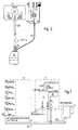
- Figure 1 shows the kit according to the invention, which is intended for installation in a vehicle for radio transmission of information.
- the kit has first and second assemblies 1 and 3, respectively. Both units 1 and 3 are here, for example, electrically connected to a hands-free device 5 within a vehicle, not shown.
- the first structural unit 1 is constructed in a single housing.
- the housing includes an antenna base, which supports the antenna 7 for telecommunications transmissions, as well as a GPS (G lobal- Positioning System) and -Empfangs- - schemes fürsaku recognized as a geographic location evaluation unit for determining the position.
- This GPS reception and data processing unit provides an exact localization of the vehicle carrying the antenna. So that the first assembly 1 can be easily attached to the vehicle roof, it has a magnetic base, not shown. Because of this magnetic base and the plug-in connection with the second structural unit 3 described below, the first structural unit 1 can be installed on other vehicles as the one that is more easily exchangeable than the first, more expensive one.
- the second module 3 has a control unit 9 containing the software and a voltage stabilizer 11 connected to it for keeping the supply voltage of the existing electronic components or the optical display 13 listed below and a serial EEPROM 15 as an information memory.
- the second structural unit 3 is also designed as a single housing.
- the second assembly 3 is designed as a stick-on key mat. A housing in the usual sense is therefore no longer available.
- the second structural unit 3 can still be referred to as a single housing, since it is self-contained and is protected from the outside.
- buttons n 19 to 21 are arranged on the mat top 17 as part of a trigger unit for manually triggering a breakdown emergency call, a help call for informing the police and ambulance, and a service call for general information, such as route information, tourist information, etc.
- the optical display 13 with green and red LEDs is inserted into the upper side 17 .
- the electrical connections of the control unit 9 to the buttons 19 to 21 and to the two LEDs are indicated schematically in FIG. 1 by the two integrated line pairs e 23a and 23b .
- a contact point of the control unit 9 designated RX / TX, is connected to the unit 1 by a signal line 24 in the connection cable 25 described below.
- Another contact point of the control unit 9 designated RX / TX2 is connected to the hands-free device 5 via a signal line 27 of the connecting cable 25 .
- the kit according to the invention is connected to the hands-free device 5 in FIG .
- This hands-free device 5 is not absolutely necessary for the automatic process described below to function properly. It can be omitted, but it has some electrical connections with which very simple cabling is possible. If the hands-free system is not available, a connecting cable 25 configured differently must be used.
- the hands-free device 5 shown in Figure 1 has a connection 29 to a car battery, not shown, and a connection 30 which is connected to the vehicle ignition. It can then also be established via the communications link whether the vehicle ignition is switched on. Another connection 31 serves to mute a car radio in order to obtain better communication in the event of message traffic in the vehicle.
- a speaker (not shown) belonging to an optional hands-free device can be connected to a connection 32 . The transition to a mobile phone is based on this optional mobile phone.
- a microphone (not shown) can be connected to a connector 33 .
- a connection 34 is connected to the units 1 and 3 via the connecting cable 25 and is used in particular for the power supply and for extending and extending the antenna 7 .
- the hands-free device 5 and the two structural units 1 and 3 are connected to one another via an earth conductor 41 .
- the connecting cable 25 has a plug 35 with which it can be detachably connected to the first structural unit 1 . 3 from the spout 7 of the plug 35, a first wiring harness 39 goes to the second module 5 and is connected captively with this.
- the cable harness 39 contains the signal lines 24 and 27 and the lines for the power supply.
- a second cable harness 40 is led out of the grommet 37 .
- This cable loom 40 later branches into three cable sub-lanes 41, 42 and 43 .
- the lower cable strand 41 is used for grounding and is connected to a ground connection 45 of the hands-free device 5 , if it is present, otherwise to the vehicle chassis.
- the lower cable strand 42 is used for the power supply and is connected to the connection 34 of the hands-free device 5 , if it is present, otherwise to the cigarette lighter (not shown).
- the cable lower line 43 contains the signal line 27 and is led to the hands-free device 5 , but can be connected to a cell phone in the absence thereof.
- the control unit 9 receives location data from the evaluation unit, which processes it appropriately and stores it in the information memory 15 , in which these new data previously determined are overwritten. Is z. If, for example, the emergency call button 20 is pressed, only a call is set up for a specific, predetermined service number and the data telegram is sent in accordance with the subsequent clarifications. The user is identified in the call only by the intrinsic properties of the transmission of the telephone number and in the data telegram by the transmission of the serial number of the second module. After pressing the emergency button 20, the control unit 9 also checks whether there is a registration in the home network.
- the generally valid emergency number "112" is dialed from the information store 15 and the emergency call is sent. Since the normal emergency call receiving stations cannot yet receive a position message, the current position determined by GPS is not yet transmitted, but can also be transmitted later. If the emergency call is triggered, the optical display 13 lights up red.
- the optical display 13 lights up green, while the connection is being established, a blinking green is present.
- the optical display flashes red. If there is an indentation, the automatic selection takes place with the number available in the memory 15 , a location is transmitted with data from GPS and possibly further data already stored in the memory. At the moment when the connection is established, the visual display 13 lights up green. If no connection is established here either, the optical display flashes red.
- the GPS unit in the structural unit 1 continuously determines the position when it is switched on.
- the data for this are stored in the memory 15 , ie continuously overwritten.
- the control unit 9 sets up the call and then sends the data telegram when the connection is established.
- a data telegram from the control center receiving the data to control processes and an acknowledgment of receipt are not transmitted.
- the module 3 only initiates the establishment of a call to a certain previously stored service number. All other processes in the handling of the call are carried out with the existing hands-free device. There is no user authentication; the data is not encrypted; Also, a radio processing center (head office) does not send an activation profile for the end device in the vehicle. The integrity of the data sent is also not checked. The user is identified in the call by the intrinsic property of the transmission of the telephone number. In the data telegram, it is carried out by transmitting a serial number stored in the memory 15 . With all of these measures, previous software processes are reduced, which means that the greatly simplified hardware structure mentioned above can only be achieved. A conversation with an operator in the processing center (head office) and the call being aborted are carried out using the above-mentioned hands-free facility, which accepts the mobile phone.
- the emergency call has top priority.
- An emergency call cancels any other service or phone call.
- the button 20 must be pressed for at least two seconds. Other security measures are also possible.
- the control unit 9 When triggered by a manual keystroke, the control unit 9 first queries the mobile phone for the current status (for example, whether it is logged into the home network). Only then is the data telegram with the location of the vehicle sent to the control center while setting up the call. If the "home network" is not available but the radio coverage is provided by another network, no data telegram is sent and a call to the emergency number 112 is established. The conversation with an operator in a processing station and the call being aborted are carried out via the above-mentioned hands-free facility which receives the mobile radio telephone.
- buttons 19 to 21 on the second module 3 instead of the three buttons 19 to 21 on the second module 3 , only a single button, preferably only the emergency button, can also be provided. However, you can also provide more than just three buttons.
- a magnetic base for fastening the first structural unit 1 to the vehicle roof instead of a magnetic base for fastening the first structural unit 1 to the vehicle roof, other holding elements can of course also be used. It can also be screwed on. A simple exchange is then no longer possible. A so-called squeegee can also be used.
- the second structural unit 3 which is mainly operated by vehicle occupants, usually the vehicle driver, is attached in a position which is easy to operate. It has now been shown that this position is not the same for every vehicle driver. For this reason, the second assembly 3 has also been designed as a stick-on key mat. In order to give an operator a completely free choice of position for the second control unit in the vehicle, it has not only been produced so that it can be stuck on, in particular removed and re-stuck on, but has also been designed in such a way that electrical connecting cables are not required.
- FIG. 1 Such an arrangement is now shown in FIG .
- a second structural unit 50 with the same properties as the structural unit 3 is formed in two parts with the partial units 51 and 53 .
- the sub-unit 51 is now also designed as a key mat with three keys 55 to 57 for breakdown assistance, emergency calls and service.
- This key mat also has a display 59 which is analogous to the optical display 13 .
- the subunit 51 is energetically and signallessly connected to the subunit 53 .
- the connection between the two subunits 51 and 53 takes place via the two antennas 61a and 61b coupled to one another.
- the sub-unit 51 has a transmit / receive module 61 and a control module 63 , which performs the circuitry and logic combination for the key functions and the display.
- the control module 63 generates a direct current from high-frequency radiation received with the receiver module, which is stored in a rechargeable energy storage r 65 .
- a mini button cell is used as the energy store, since the electrical components of the component 50 have only a low power requirement.
- Data can also be transmitted via the antenna 62a of the unit 50 with almost no energy consumption by modulation and in particular by attenuation of the electromagnetic field.
- the sub-unit 53 has the remaining components analogous to the unit 1 .
- the subunit 53 also has an antenna 62b and a transmit / receive component 67 .
- Voltage stabilizer, control unit and information memory are designed analogously to the components of the one-piece unit 3 and are therefore also identified by the same reference numerals 11, 9 and 15 .
- the transmit / receive module 61 of the sub-unit 51 immediately sends the corresponding data telegram to the transmit / receive module 67 via the antenna 62a .
- the duration of the pressure on the key 56 is measured by the control unit 9 . If the time period required to trigger the emergency call is exceeded by 2 seconds, the data telegram is sent to the processing point by setting up the call via antenna 7 .
- a shock sensor can also be installed in the subunit 51 instead of the emergency call button 56 or in addition to it. In the event of a vehicle accident, an emergency call is now automatically initiated via this shock sensor.
- the subunit no longer has to be connected to cables, it can be installed in the vehicle can be installed at almost any point, where you then click on buttons and / or display can be omitted.
- infrared can of course also be used Radiation can be used with appropriate transmitters and receivers.
- the hardware expenditure can be reduced further as a result:
- the control of the mobile phone in response to this triggering is inserted as a software module in the controller of the unit 1 , which is then next to the calculation of the geographical location must also respond to this trigger signal.
- the computing power of a GPS processor is completely sufficient to safely process this process.
- the entire arrangement is then reduced to the use of a plug with the cable 40 and the connections 41 , 42 and 43 which is suitably converted to the plug 35 . Only this unit 1 is then connected to this modified plug.
- the entire structural unit 3 could also be connected to the structural unit 1 in a contactless manner.
- limit values in the driver's cabin must not be exceeded.
- unit 1 would also be configured independently of the vehicle electrical system, for example with its own battery supply.
Abstract
Description
Die Erfindung betrifft einen Bausatz gemäß Patentanspruch 1, dessen Anordung und Verwendung in einem Fahrzeug gemäß der Oberbegriffe der Patentansprüche 8 bzw. 10.The invention relates to a kit according to claim 1, its arrangement and Use in a vehicle according to the preambles of claims 8 and 10th
Im Bereich der Verkehrstelematik wurden in der DE-U 296 00 600, der EP-A 0 679 041 und der WO 97/25223 Vorschläge unterbreitet, wie im Zusammenhang mit einem GPS (Global Positioning System) in einem Fahrzeug Pannen-, Unfall-, Navigationshilfe usw. angefordert werden konnten.In the field of traffic telematics, DE-U 296 00 600, EP-A 0 679 041 and WO 97/25223 makes suggestions, such as in connection with a GPS (Global Positioning System) in a vehicle breakdown, accident, navigation aid etc. could be requested.
Gemeinsam ist dem hier aufgeführten Stand der Technik die zwingende Verwendung eines Mobiltelefons für die Datenübertragung zu einer Bearbeitungsstelle bzw. Verteilerstelle. Es wird ferner eine umfangreiche Steuerelektronik benötigt, welche den Benützer authentifiziert, die Datenübertragung verschlüsselt, Dienstberechtigungen vergibt bzw. eine Neukonfiguration des Übermittlungssystems vornimmt. Hieraus ergibt sich ein enormer Soft- und Hardwareaufwand im betreffenden Endgerät.Common to the prior art listed here is the mandatory use a mobile phone for data transmission to a processing point or distribution point. Extensive control electronics are required, which the user authenticated, data transmission encrypted, service authorizations granted or reconfiguring the transmission system. From this results there is an enormous amount of software and hardware in the relevant device.
Aufgabe der Erfindung ist es, eine einfache und kostengünstige Vorrichtung zu schaffen, welche die bisherige Vorrichtung ersetzt, welche einen aufwendigen Soft- und Hardwareaufwand benötigten, wobei die erfindungsgemäße Vorrichtung sich zudem mit einem minimalen Montageaufwand in ein Fahrzeug einbauen lassen soll.The object of the invention is to provide a simple and inexpensive device, which replaces the previous device, which is a complex software and Hardware expenditure required, the device according to the invention also can be installed in a vehicle with minimal assembly effort.
Der minimale Montageaufwand wird erfindungsgemäß dadurch erreicht, daß ein Aufbau mit einem einfachen Endgerät geschaffen wird, welches mit optimierten Softwareabläufen kombiniert eine zuverlässige Hilfeleistung, z.B. einen Notruf ermöglicht. Hierzu ist ein erfindungsgemäßer Bausatz geschaffen worden, der für die Zusatzfunktionen zur Verkehrstelematik lediglich eine erste und eine zweite Baueinheit aufweist. Nur hierdurch ist ein minimaler Montageaufwand erreichbar. Beide Baueinheiten können eingehäusig ausgebildet sein und werden im Fahrzeug örtlich voneinander getrennt angeordnet. Die signalmäßige Verbindung kann dann lediglich durch ein Kabel erfolgen oder wie in einer besonderen Ausgestaltung schnurlos über eine elektromagnetische Strahlung, welche im hochfrequenten sowie auch im infraroten Bereich liegen kann. Die erste Baueinheit enthält eine Antenne zusammen mit einer den geographischen Ort erkennenden Auswerteeinheit, wie beispieslweise einer GPS-Einheit. Die zweite Baueinheit kann als Auslöseeinheit eine Tasten aufweisende Bedieneinheit mit einem Informationsspeicher haben. Anstelle einer GPS-Einheit kann auch eine GLONASS-Einheit (Global Navigation Satellite System) verwendet werden.The minimal installation effort is achieved according to the invention in that a structure is created with a simple terminal device which, combined with optimized software processes, enables reliable assistance, for example an emergency call. For this purpose, a kit according to the invention has been created which has only a first and a second module for the additional functions for traffic telematics. This is the only way to achieve a minimal installation effort. Both units can be constructed in one housing and are arranged locally separated from one another in the vehicle. The signal connection can then only be made by a cable or, as in a special embodiment, wirelessly via electromagnetic radiation, which can be in the high-frequency and also in the infrared range. The first structural unit contains an antenna together with an evaluation unit that recognizes the geographical location, such as a GPS unit. The second structural unit can have a control unit with buttons and an information memory as a trigger unit. Instead of a GPS unit, a GLONASS unit may be used (Glo bal Na vigation S atellite S ystem).
Die erste Baueinheit wird man in vorteilhafter Weise mit einem Magnetfuß ausrüsten, damit sie problemlos und einfach auf einem Fahrzeugdach anbringbar und wieder wegnehmbar ist.The first structural unit will advantageously be equipped with a magnetic base, so that they can be easily and easily attached to a vehicle roof and back is removable.
In bevorzugter Weise ist die zweite Baueinheit als Tastenmatte ausgebildet, in welche die entsprechenden elektronischen Bauelemente bzw. Anzeigeelemente integriert sind. Diese Matte kann dann in der Fahrzeuginnenseite dort angeklebt werden, wo sie gut sichtbar bzw. bedienbar ist. The second structural unit is preferably designed as a key mat, into which the corresponding electronic components or display elements are integrated. This mat can then be glued to the inside of the vehicle where it is good is visible or operable.
Die erste Baueinheit als die teurere ist auswechselbar ausgebildet, während die hierzu bedeutend billigere zweite Baueinheit im Fahrzeuginnenraum eingeklebt wird und in der Regel dort verbleibt. Man wird sie jedoch lösbar ausbilden, damit der Fahrer bzw. sein Beifahrer einen optimalen Ort wählen können.The first structural unit as the more expensive one is designed to be exchangeable, while the latter significantly cheaper second unit is glued in the vehicle interior and in usually stays there. However, they will be designed to be detachable so that the driver or his passenger can choose an optimal location.
Weitere Vorteile der Erfindung sowie Ausführungsvarianten ergeben sich aus dem untenstehenden Text.Further advantages of the invention as well as design variants result from the following Text.
Im folgenden werden Beispiele des erfindungsgemässen Bausatzes anhand der Zeichnungen näher erläutert. Es zeigen:
- Fig. 1
- ein elektrisches Blockschaltbild eines beispielsweise mit einer Freisprecheinrichtung in einem Fahrzeug verbundenen erfindungsgemässen Bausatzes,
- Fig. 2
- eine beispielsweise Ausführung einer elektrischen Verbindung zu der Darstellung in Figur 1 und
- Fig. 3
- eine Variante einer zweiten Baueinheit des in Figur 1 dargestellten Bausatzes.
- Fig. 1
- 2 shows an electrical block diagram of a kit according to the invention connected, for example, to a hands-free device in a vehicle,
- Fig. 2
- an example of an electrical connection to the representation in Figure 1 and
- Fig. 3
- a variant of a second unit of the kit shown in Figure 1 .
Figur 1 zeigt den erfindungsgemäßen Bausatz, der für eine Montage in einem Fahrzeug
zur funktechnischen Übermittlung von Informationen vorgesehen ist. Der Bausatz
hat ein erste und eine zweite Baueinheit 1 bzw. 3. Beide Baueinheiten 1 und 3 sind hier
beispielsweise mit einer Freisprecheinrichtung 5 innerhalb eines nicht dargestellten
Fahrzeugs elektrisch verbunden. Figure 1 shows the kit according to the invention, which is intended for installation in a vehicle for radio transmission of information. The kit has first and
Die erste Baueinheit 1 ist eingehäusig aufgebaut. Das Gehäuse beinhaltet einen Antennenfuß,
der die Antenne 7 für die nachrichtentechnischen Übermittlungen trägt, sowie
eine GPS (Global-Positioning System)-Empfangs- und -datenverarbeitungseinheit
als eine den geographischen Ort erkennende Auswerteeinheit zur Positionsbestimmung.
Mit dieser GPS-Empfangs- und -datenverarbeitungseinheit ist eine exakte Lokalisierung
des die Antenne tragenden Fahrzeugs gegeben. Damit die erste Baueinheit 1
problemlos auf dem Fahrzeugdach befestigbar ist, hat sie einen nicht dargestellten
Magnetfuß. Aufgrund dieses Magnetfußes und der unten beschriebenen steckbaren
Verbindung mit der zweiten Baueinheit 3 kann die erste Baueinheit 1 als das gegenüber
dem ersten teureren problemlos austauschbar auch an anderen Fahrzeugen installiert
werden.The first structural unit 1 is constructed in a single housing. The housing includes an antenna base, which supports the antenna 7 for telecommunications transmissions, as well as a GPS (G lobal- Positioning System) and -Empfangs- -datenverarbeitungseinheit recognized as a geographic location evaluation unit for determining the position. This GPS reception and data processing unit provides an exact localization of the vehicle carrying the antenna. So that the first assembly 1 can be easily attached to the vehicle roof, it has a magnetic base, not shown. Because of this magnetic base and the plug-in connection with the second
Die zweite Baueinheit 3 hat eine die Software enthaltende Steuereinheit 9 sowie einen
mit dieser verbundenen Spannungskonstanthalter 11 zum Konstanthalten der Versorgungsspannung
der vorhandenen elektronischen Bauelemente bzw. der unten angeführten
optischen Anzeige 13 und ein serielles EEPROM 15 als Informationsspeicher.
Auch die zweite Baueinheit 3 ist hier in einer bevorzugten Ausführungsform eingehäusig
ausgeführt. Die zweite Baueinheit 3 ist als aufklebbare Tastenmatte ausgebildet.
Ein Gehäuse im landläufigen Sinn ist somit nicht mehr vorhanden. Man kann die zweite
Baueinheit 3 jedoch immer noch als eingehäusig bezeichnen, da es in sich abgeschlossen
und nach außen geschützt ausgebildet ist.The
Auf der Mattenoberseite 17 sind hier beispielsweise drei Tasten 19 bis 21 als Teil einer
Auslöseeinheit für ein manuelles Auslösen eines Pannennotrufes, eines Hilferufes zur
Information von Polizei und Ambulanz sowie eines Servicerufes für allgemeine Informationen,
wie Streckeninformation, touristische Informationen etc. angeordnet. Ferner
ist in die Oberseite 17 die optische Anzeige 13 mit grünen und roten LED's eingesetzt.
Die elektrischen Verbindungen der Steuereinheit 9 zu den Tasten 19 bis 21 sowie zu
den beiden LED's sind in Figur 1 schematisch durch die beiden integrierten Leitungspaare
23a und 23b angedeutet. Ein Kontaktpunkt der Steuereinheit 9, mit RX/TX bezeichnet,
ist mit einer Signalleitung 24 im unten beschriebenen Verbindungskabel 25
mit der Baueinheit 1 verbunden. Ein weiterer, mit der Bezeichnung RX/TX2 versehener
Kontaktpunkt der Steuereinheit 9 ist über eine Signalleitung 27 des Verbindungskabels
25 mit der Freisprecheinrichtung 5 verbunden.For example, three
Der erfindungsgemäße Bausatz ist in Figur 1 mit der Freisprecheinrichtung 5 verbunden.
Für eine einwandfreie Funktion des unten beschriebenen automatischen Ablaufs
ist diese Freisprecheinrichtung 5 nicht zwingend notwendig. Auf sie kann verzichtet
werden, sie weist jedoch einige elektrische Anschlüsse auf, mit denen eine sehr einfache
Verkabelung möglich ist. Ist die Freisprecheinrichtung nicht vorhanden, ist ein entsprechend
anders konfiguriertes Verbindungskabel 25 zu verwenden.The kit according to the invention is connected to the hands-
Die in Figur 1 gezeigte Freisprecheinrichtung 5 hat einen Anschluß 29 an eine nicht
dargestellte Autobatterie sowie einen Anschluß 30, der mit der Fahrzeugzündung verbunden
ist. Hiermit ist dann auch über die nachrichtentechnische Verbindung feststellbar,
ob die Fahrzeugzündung eingeschaltet ist. Ein weiterer Anschluß 31 dient zur
Stummschaltung eines Autoradios, um eine bessere Verständigung bei einem Nachrichtenverkehr
im Fahrzeug zu erhalten. An einem Anschluß 32 ist ein nicht dargestellter,
zu einer fakultativen Freisprecheinrichtung gehörender Lautsprecher anschließbar.
Der Übergang zu einem Mobiltelefon erfolgt auf der Basis dieses fakultativen Mobiltelefons.
An einem Anschluß 33 ist ein nicht dargestelltes Mikrofon anschließbar. Ein
Anschluß 34 ist über das Verbindungskabel 25 mit den Baueinheiten 1 und 3 verbunden
und dient insbesondere zur Stromversorgung sowie zum Ein- und Ausfahren der
Antenne 7. Die Freisprecheinrichtung 5 und die beiden Baueinheiten 1 und 3 sind über
einen Erdleiter 41 miteinander verbunden.The hands-
Das Verbindungskabel 25 hat einen Stecker 35, mit dem es an die erste Baueinheit 1
lösbar anschließbar ist. Aus der Tülle 37 des Steckers 35 geht ein erster Kabelstrang
39 zur zweiten Baueinheit 5 und ist mit diesem unverlierbar fest verbunden. Der
Kabelstrang 39 enthält die Signalleitungen 24 und 27 sowie die Leitungen für die
Stromversorgung. Aus der Tülle 37 wird neben dem ersten Kabelstrang 39 ein zweiter
Kabelstrang 40 herausgeführt. Dieser Kabelstrang 40 verzweigt sich später in drei Kabelunterstränge
41, 42 und 43. Der Kabelunterstrang 41 dient zur Erdung und wird an
einen Erdungsanschluß 45 der Freisprecheinrichtung 5 angeschlossen, sofern diese
vorhanden ist, ansonsten an das Fahrzeugschassis. Der Kabelunterstrang 42 dient zur
Stromversorgung und wird an den Anschluß 34 der Freisprecheinrichtung 5 angeschlossen,
sofern diese vorhanden ist, ansonsten an den nicht dargestellten Zigarettenanzünder.
Der Kabelunterstrang 43 enthält die Signalleitung 27 und wird zur Freisprecheinrichtung
5 geführt, kann aber bei deren Fehlen mit einem Handy verbunden
werden.The connecting
Beim Betrieb des im Fahrzeug eingebauten Bausatzes empfängt die Steuereinheit 9
Ortsdaten von der Auswerteeinheit, welche diese geeignet bearbeitet und im Informationsspeicher
15 speichert, in dem diese neuen Daten vorhergehend ermittelten überschrieben
werden. Wird z. B. die Notruftaste 20 gedrückt, so wird nur der Aufbau eines
Rufes zu einer bestimmten, vorgegebenen Service-Rufnummer vorgenommen und
entsprechend der nachfolgenden Abklärungen das Datentelegramm gesendet. Eine
Identifizierung des Benutzers erfolgt im Ruf nur durch netzimmanente Eigenschaften
der Übertragung der Telefonnummer sowie in dem Datentelegramm durch Übertragung
der Seriennummer der zweiten Baueinheit. Nach Drücken der Notruftaste 20 prüft ferner
die Steuereinheit 9, ob eine Einbuchung im Heimnetz besteht. Besteht diese Einbuchung
nicht, wird durch einen entsprechenden Abruf aus dem Informationsspeicher
15 die allgemein gültige Notrufnummer "112" gewählt und der Notruf ausgesandt.
Da im Augenblick die normalen Notrufempfangsstellen eine Positionsmitteilung noch
nicht empfangen können, wird die mit GPS ermittelte augenblickliche Ortsposition noch
nicht ausgesendet, kann aber später auch mit ausgesendet werden. Ist der Notrufausgelöst,
leuchtet die optische Anzeige 13 rot auf.During operation of the kit installed in the vehicle, the
Ist jedoch eine Einbuchung in das Heimnetz bei Drücken der Notruftaste gegeben, wird
die entsprechende Nummer für das Heimnetz gewählt und die mit GPS ermittelte Ortsposition
durchgegeben. Ist die Verbindung aufgebaut, leuchtet die optische Anzeige 13
grün, während des Aufbaus ist ein blinkendes Grün vorhanden.However, if the home network is logged on when the emergency button is pressed, the corresponding number is dialed for the home network and the location determined using GPS is transmitted. If the connection is established, the
Wird ein Pannenrufdurch Drücken der Taste 19 ausgelöst und ist eine entsprechende
Einbuchung im Heimnetz nicht vorhanden, so blinckt die optische Anzeige rot. Ist eine
Einbuchtung vorhanden, so erfolgt die automatische Anwahl mit der im Speicher 15
vorhandenen Nummer, eine Ortsübermittlung mit Daten von GPS und eventuell weiteren
im Speicher bereits abgespeicherten Daten. In dem Augenblick, in dem die Verbindung
zustande gekommen ist, leuchtet die optische Anzeige 13 grün. Kommt auch hier
keine Verbindung zustande, blinkt die optische Anzeige rot.If a breakdown call is triggered by pressing
Die GPS-Einheit in der Baueinheit 1 führt im eingeschalteten Zustand eine kontinuierliche
Positionsbestimmung durch. Die Daten hierzu werden im Speicher 15 abgespeichert,
d.h. laufend überschrieben. Die Steuereinheit 9 baut den Ruf auf und versendet
bei stehender Verbindung dann das Datentelegramm. Ein Datentelegramm der die Daten
empfangenden Zentrale zur Steuerung von Abläufen und eine Empfangsbestätigung
wird nicht übertragen. Es erfolgt auch keine Verschlüsselung der Daten. Es werden
lediglich Daten gesandt. Aus diesen Daten wird dann in der Zentrale die entsprechende
auszuführende Dienstleistung von einem Operator erkannt und die entsprechenden
Handlungen in Auftrag gegeben.The GPS unit in the structural unit 1 continuously determines the position when it is switched on. The data for this are stored in the
Die Baueinheit 3 initiiert nur den Aufbau eines Rufes zu einer bestimmten vorher abgespeicherten
Service-Nummer. Alle weiteren Abläufe in der Behandlung des Rufes werden
mit der vorhandenen Freisprechvorrichtung vorgenommen. Auf eine Benutzerauthentikation
wird verzichtet; es erfolgt keine Verschlüsselung der Daten; auch versendet
eine funktechnische Bearbeitungsstelle (Zentrale) kein Freischaltungsprofil für
das Endgerät im Fahrzeug. Eine Überprüfung der Integrität der gesendeten Daten wird
ebenfalls nicht vorgenommen. Die Identifizierung des Benutzers erfolgt im Ruf durch
die netzimmanente Eigenschaft der Übertragung der Telefonnummer. In dem Datentelegramm
erfolgt sie durch eine Übertragung einer im Speicher 15 abgespeicherten Seriennummer.
Durch all diese Maßnahmen werden bisherige Softwareabläufe verringert,
wodurch der oben erwähnte stark vereinfachte Hardwareaufbau erst erreichbar ist. Ein
Gespräch mit einem Operator in der Bearbeitungsstelle (Zentrale) und der Abbruch des
Rufes erfolgen mit der oben genannten Freisprecheinrichtung, die das Mobiltelefon aufnimmt.The
Der Notruf hat oberste Priorität. Ein Notruf bricht jeden anderen Dienst und jedes Telefongespräch
ab. Um zu verhindern, daß ein Notrufversehentlich ausgelöst wird, muß
die Taste 20 mindestens zwei Sekunden gedrückt werden. Andere Sicherungsmaßnahmen
sind ebenfalls möglich.The emergency call has top priority. An emergency call cancels any other service or phone call. To prevent an emergency call from being triggered accidentally, the
Bei einem Auslösen durch einen manuellen Tastendruck fragt die Steuereinheit 9 vom
Mobiltelefon zuerst den aktuellen Zustand ab (z.B. ob im Heimnetz eingebucht ist). Erst
anschließend wird das Datentelegramm mit der Ortsposition des Fahrzeugs an die
Zentrale unter Aufbau des Rufes gesandt. Ist das "Heimnetz" nicht verfügbar aber die
Funkversorgung durch ein anderes Netz gegeben, wird kein Datentelegramm gesendet
und ein Rufzur Notrufnummer 112 aufgebaut. Das Gespräch mit einem Operator in
einer Bearbeitungsstelle und der Abbruch des Rufes erfolgen über die oben genannte
Freisprecheinrichtung, die das Mobilfunktelefon aufnimmt.When triggered by a manual keystroke, the
Anstelle der drei Tasten 19 bis 21 auf der zweiten Baueinheit 3 kann auch nur eine
einzige, bevorzugt nur die Notruftaste, vorgesehen werden. Man kann jedoch auch
mehr als nur drei Tasten vorsehen.Instead of the three
Anstelle eines Magnetfußes für die Befestigung der ersten Baueinheit 1 auf dem Fahrzeugdach, können selbstverständlich auch andere Halteelemente benützt werden. Sie kann auch angeschraubt werden. Ein einfaches Auswechseln ist dann allerdings nicht mehr gegeben. Es kann auch ein sog. Saugfuß verwendet werden.Instead of a magnetic base for fastening the first structural unit 1 to the vehicle roof, other holding elements can of course also be used. It can also be screwed on. A simple exchange is then no longer possible. A so-called squeegee can also be used.
Wie oben beschrieben, wird die zweite Baueinheit 3, welche hauptsächlich von Fahrzeuginsassen,
in der Regel dem Fahrzeuglenker bedient wird, in einer gut bedienbaren
Position angebracht. Es hat sich nun gezeigt, daß diese Position nicht für jeden Fahrzeuglenker
dieselbe ist. Aus diesem Grund ist die zweite Baueinheit 3 auch als aufklebbare
Tastenmatte ausgebildet worden. Um einem Bediener nun eine vollkommen
freie Positionswahl der zweiten Bedieneinheit im Fahrzeug zu geben, ist diese nicht nur
aufklebbar, insbesondere abnehmbar und wieder aufklebbar hergestellt worden, sondern
zusätzlich noch derart ausgebildet worden, daß elektrische Verbindungskabel
entfallen.As described above, the second
In Figur 3 ist nun eine derartige Anordnung dargestellt. Im Gegensatz zu der in Figur 1
dargestellten Baueinheit 3 ist eine zweite Baueinheit 50 mit denselben Eigenschaften
wie die Baueinheit 3 zweiteilig mit den Teileinheiten 51 und 53 ausgebildet. Die Teileinheit
51 ist nun ebenfalls als Tastenmatte mit drei Tasten 55 bis 57 für Pannenhilfe, Notruf
und Service ausgebildet. Ferner hat diese Tastenmatte eine zur optischen Anzeige
13 analoge Anzeige 59.Such an arrangement is now shown in FIG . In contrast to the
Die Teileinheit 51 ist energetisch und signalmäßig kontaktlos mit der Teileinheit 53 verbunden.
Die Verbindung zwischen beiden Teileinheiten 51 und 53 erfolgt über die beiden
miteinander gekoppelten Antennen 61a und 61b. Zusätzlich zur Antenne 61a hat
die Teileinheit 51 einen Sende-/Empfangsbaustein 61 und einen Steuerbaustein 63,
der die schaltungstechnische und logische Verknüpfung für die Tastenfunktionen und
die Anzeige vornimmt. Ferner erzeugt der Steuerbaustein 63 aus einer mit dem Empfangsbaustein
empfangenen Hochfrequenzstrahlung einen Gleichstrom, der in einen
aufladbaren Energiespeicher 65 gespeichert wird. Als Energiespeicher wird eine Miniknopfzelle
verwendet, da die elektrischen Bauelemente des Bauteils 50 nur einen geringen
Strombedarf aufweisen. Auch kann eine Datenaussendung über die Antenne
62a der Baueinheit 50 nahezu ohne Energieverbrauch durch Modulation und insbesondere
durch Dämpfung des elektromagnetischen Feldes erfolgen.The
Die Teileinheit 53 weist die restlichen Bauelemente analog zur Baueinheit 1 auf. Ferner
hat die Teileinheit 53 eine Antenne 62b und einen Sende-/Empfangsbaustein 67.
Spannungskonstanthalter, Steuereinheit und Informationsspeicher sind analog zu den
Bausteinen der einteiligen Baueinheit 3 ausgebildet und somit auch mit den gleichen
Bezugszeichen 11, 9 und 15 gekennzeichnet.The sub-unit 53 has the remaining components analogous to the unit 1 . The
Wird jetzt z. B. die Notruftaste 56 gedrückt, so sendet der Sende-/Empfangsbaustein
61 der Teileinheit 51 sofort das entsprechende Datentelegramm über die Antenne
62a an den Sende-/Empfangsbaustein 67. Im ständigen Datenaustausch wird die
Dauer des Drucks auf die Taste 56 durch die Steuereinheit 9 gemessen. Ist der zum
Auslösen des Notrufs notwendige Zeitraum von 2 Sekunden überschritten, wird das
Datentelegramm an die Bearbeitungsstelle unter Aufbau des Rufes über die Antenne 7
gesandt.Now z. For example, if the
Anstelle einen Notruf über den Tastendruck auszusenden, kann auch in die Teileinheit
51 ein Schocksensor anstelle der Notruftaste 56 oder zusätzlich zu dieser eingebaut
werden. Bei einem Fahrzeugunfall wird nun automatisch ein Notruf über diesen
Schocksensor initiiert.Instead of sending an emergency call by pressing a button, a shock sensor can also be installed in the
Da die Teileinheit nicht mehr mit Kabeln verbunden werden muß, kann sie im Fahrzeug an nahezu beliebigen Stellen eingebaut werden, wobei man dann hier auf Tasten und/oder Anzeige verzichten kann.Since the subunit no longer has to be connected to cables, it can be installed in the vehicle can be installed at almost any point, where you then click on buttons and / or display can be omitted.
Anstelle einer Hochfrequenzstrahlung kann selbstverständlich auch eine infrarote Strahlung mit entsprechenden Sendern und Empfängern verwendet werden.Instead of high-frequency radiation, infrared can of course also be used Radiation can be used with appropriate transmitters and receivers.
Wird von der Teileinheit 51 bzw. von der einteiligen Baueinheit 3 nur eine automatische
Notruffunktion ausgeführt, so kann hierdurch der Hardwareaufwand weiter reduziert
werden: Die Steuerung des Mobiltelefons als Reaktion auf diese Auslösung wird als
Softwaremodul in den Controller der Baueinheit 1 eingefügt, der dann neben der Berechnung
der geographischen Lage auch auf dieses Auslösesignal reagieren muß. Die
Rechenleistung eines GPS-Prozessors reicht völlig aus, um diesen Ablauf sicher abzuarbeiten.
Die gesamte Anordnung reduziert sich dann auf die Verwendung eines zum
Stecker 35 geeignet umgebauten Steckers mit dem Kabel 40 und den Anschlüssen 41,
42 und 43. An diesem modifizierten Stecker ist dann nur noch die Baueinheit 1 angeschlossen.If only an automatic emergency call function is carried out by the sub-unit 51 or by the one-
Anstelle nur die Teileinheit 51 kontaktlos anzuordnen, könnte auch die ganze Baueinheit
3 kontaktlos mit der Baueinheit 1 verbunden werden. Es ist jedoch hierbei zu beachten,
daß bei einer Verwendung von Hochfrequenzstrahlung für den Energietransport
Grenzwerte in der Fahrerkabine nicht überschritten werden dürfen. In diesem Fall
würde lediglich von der Baueinheit eine Antenne in die Fahrerkabine, z. B. durch einen
Schlitz zwischen seitlichem Fenster und dessen Rahmen gezogen. Die Baueinheit 1
würde man in diesem Fall ebenfalls vom Bordnetz unabhängig z.B. mit einer eigenen
Batterieversorgung ausgestalten.Instead of only arranging the
Claims (10)
Priority Applications (1)
| Application Number | Priority Date | Filing Date | Title |
|---|---|---|---|
| DE29924325U DE29924325U1 (en) | 1998-10-08 | 1999-03-18 | Assembly kit and its arrangement and use in a vehicle |
Applications Claiming Priority (2)
| Application Number | Priority Date | Filing Date | Title |
|---|---|---|---|
| CH203898 | 1998-10-08 | ||
| CH203898 | 1998-10-08 |
Publications (1)
| Publication Number | Publication Date |
|---|---|
| EP0992409A1 true EP0992409A1 (en) | 2000-04-12 |
Family
ID=4224489
Family Applications (1)
| Application Number | Title | Priority Date | Filing Date |
|---|---|---|---|
| EP99105595A Withdrawn EP0992409A1 (en) | 1998-10-08 | 1999-03-18 | Assembly kit as well as its layout and use in a vehicle |
Country Status (1)
| Country | Link |
|---|---|
| EP (1) | EP0992409A1 (en) |
Cited By (1)
| Publication number | Priority date | Publication date | Assignee | Title |
|---|---|---|---|---|
| DE10146979A1 (en) * | 2001-09-24 | 2003-06-18 | Harman Becker Automotive Sys | Upgrading of an existing motor vehicle radio by addition of one or more functions, by upgrading radio software or hardware, especially for addition of an emergency function, e.g. for sending an emergency text or SMS message |
Citations (7)
| Publication number | Priority date | Publication date | Assignee | Title |
|---|---|---|---|---|
| DE4203865A1 (en) * | 1991-08-30 | 1993-03-04 | Erich Matouschek | Alarm and alerting appts. for motor vehicle |
| US5223844A (en) * | 1992-04-17 | 1993-06-29 | Auto-Trac, Inc. | Vehicle tracking and security system |
| WO1993016452A1 (en) * | 1992-02-06 | 1993-08-19 | Simms Industries, Inc. | Personal security system |
| US5311197A (en) * | 1993-02-01 | 1994-05-10 | Trimble Navigation Limited | Event-activated reporting of vehicle location |
| WO1996018275A1 (en) * | 1994-12-08 | 1996-06-13 | Stanford Telecommunications, Inc. | System for providing simultaneous data and voice communication |
| EP0748727A1 (en) * | 1995-06-15 | 1996-12-18 | Seguridad Mapfre, Segurmap, S.A. | Safety system for vehicles |
| US5793283A (en) * | 1997-01-21 | 1998-08-11 | Davis; Ronnie | Pager vehicle theft prevention and recovery system |
-
1999
- 1999-03-18 EP EP99105595A patent/EP0992409A1/en not_active Withdrawn
Patent Citations (8)
| Publication number | Priority date | Publication date | Assignee | Title |
|---|---|---|---|---|
| DE4203865A1 (en) * | 1991-08-30 | 1993-03-04 | Erich Matouschek | Alarm and alerting appts. for motor vehicle |
| WO1993016452A1 (en) * | 1992-02-06 | 1993-08-19 | Simms Industries, Inc. | Personal security system |
| US5223844A (en) * | 1992-04-17 | 1993-06-29 | Auto-Trac, Inc. | Vehicle tracking and security system |
| US5223844B1 (en) * | 1992-04-17 | 2000-01-25 | Auto Trac Inc | Vehicle tracking and security system |
| US5311197A (en) * | 1993-02-01 | 1994-05-10 | Trimble Navigation Limited | Event-activated reporting of vehicle location |
| WO1996018275A1 (en) * | 1994-12-08 | 1996-06-13 | Stanford Telecommunications, Inc. | System for providing simultaneous data and voice communication |
| EP0748727A1 (en) * | 1995-06-15 | 1996-12-18 | Seguridad Mapfre, Segurmap, S.A. | Safety system for vehicles |
| US5793283A (en) * | 1997-01-21 | 1998-08-11 | Davis; Ronnie | Pager vehicle theft prevention and recovery system |
Cited By (2)
| Publication number | Priority date | Publication date | Assignee | Title |
|---|---|---|---|---|
| DE10146979A1 (en) * | 2001-09-24 | 2003-06-18 | Harman Becker Automotive Sys | Upgrading of an existing motor vehicle radio by addition of one or more functions, by upgrading radio software or hardware, especially for addition of an emergency function, e.g. for sending an emergency text or SMS message |
| DE10146979B4 (en) * | 2001-09-24 | 2005-09-15 | Harman Becker Automotive Systems (Becker Division) Gmbh | Car radio receiver with several function keys |
Similar Documents
| Publication | Publication Date | Title |
|---|---|---|
| DE60018263T2 (en) | BOARD COMMUNICATION SENDING DEVICE AND INFORMATION SUPPLY CENTER FOR THIS UNIT | |
| DE19922862C2 (en) | Communication device and unit for a communication device | |
| DE69930505T2 (en) | Kommunikationsschittstellenadapter | |
| DE60120537T2 (en) | Infrared communication system for vehicle | |
| DE10137850B4 (en) | Emergency information terminal and an emergency information system including the terminal | |
| DE4244468C2 (en) | Control device for an operating system | |
| EP1444664A2 (en) | Method and emergency call device for triggering an emergency call from a vehicle | |
| EP1737135B1 (en) | Car telephone installation | |
| DE102005054215A1 (en) | Portable communication device | |
| EP2822819A1 (en) | Mobile-radio-based additional electronic immobilizer having a door opener having a theft alarm | |
| DE2108602A1 (en) | Message transmission device, in particular radiotelephone system | |
| EP0376951A1 (en) | Car radio with theft protection | |
| DE19850044C2 (en) | Mobile phone holder for a vehicle | |
| DE102009023640B4 (en) | Handsfree in a vehicle | |
| EP1690409B1 (en) | Hands-free device for operating different types of mobile radio devices | |
| EP0992409A1 (en) | Assembly kit as well as its layout and use in a vehicle | |
| DE102015215332B4 (en) | Vehicle key for informing a user about a status of a means of transportation | |
| DE102009012628A1 (en) | Arrangement for sending emergency call i.e. short message service, during e.g. accident of car, has mobile telephone transceiver integrated into body control module, where body control module activates emergency call by transceiver | |
| DE19804476B4 (en) | Car radio with removable control panel | |
| EP1012992B1 (en) | Receiver in an antenna base | |
| DE10216100A1 (en) | Motor vehicle communications system combines mobile phone and navigation system to form an integral system in which the phone can be used hands free, while the navigation system can connect to the phone network via the phone | |
| EP0636071B1 (en) | Communication device for a Vehicle | |
| DE19947310A1 (en) | Motor vehicle | |
| DE10217044A1 (en) | Antenna system architecture with integrated systems | |
| DE102006007959B4 (en) | System with vehicle installation module and control system |
Legal Events
| Date | Code | Title | Description |
|---|---|---|---|
| PUAI | Public reference made under article 153(3) epc to a published international application that has entered the european phase |
Free format text: ORIGINAL CODE: 0009012 |
|
| AK | Designated contracting states |
Kind code of ref document: A1 Designated state(s): DE FR GB IT |
|
| AX | Request for extension of the european patent |
Free format text: AL;LT;LV;MK;RO;SI |
|
| 17P | Request for examination filed |
Effective date: 20001009 |
|
| AKX | Designation fees paid |
Free format text: DE FR GB IT |
|
| 17Q | First examination report despatched |
Effective date: 20020122 |
|
| STAA | Information on the status of an ep patent application or granted ep patent |
Free format text: STATUS: THE APPLICATION IS DEEMED TO BE WITHDRAWN |
|
| 18D | Application deemed to be withdrawn |
Effective date: 20020802 |