EP0994602A2 - Computer system and network performance monitoring - Google Patents
Computer system and network performance monitoring Download PDFInfo
- Publication number
- EP0994602A2 EP0994602A2 EP99306854A EP99306854A EP0994602A2 EP 0994602 A2 EP0994602 A2 EP 0994602A2 EP 99306854 A EP99306854 A EP 99306854A EP 99306854 A EP99306854 A EP 99306854A EP 0994602 A2 EP0994602 A2 EP 0994602A2
- Authority
- EP
- European Patent Office
- Prior art keywords
- computer system
- network
- performance statistics
- information
- network performance
- Prior art date
- Legal status (The legal status is an assumption and is not a legal conclusion. Google has not performed a legal analysis and makes no representation as to the accuracy of the status listed.)
- Granted
Links
- 238000012544 monitoring process Methods 0.000 title claims abstract description 28
- 238000000034 method Methods 0.000 claims abstract description 70
- 238000004891 communication Methods 0.000 claims abstract description 58
- 230000015654 memory Effects 0.000 claims abstract description 41
- 230000004044 response Effects 0.000 claims abstract description 32
- 230000002596 correlated effect Effects 0.000 claims abstract description 11
- 230000008569 process Effects 0.000 claims description 30
- 238000007726 management method Methods 0.000 claims description 21
- 238000012545 processing Methods 0.000 claims description 11
- 238000013500 data storage Methods 0.000 claims description 6
- 230000000875 corresponding effect Effects 0.000 description 14
- 239000000523 sample Substances 0.000 description 6
- 238000012552 review Methods 0.000 description 5
- 238000010586 diagram Methods 0.000 description 4
- 230000009471 action Effects 0.000 description 2
- 238000010420 art technique Methods 0.000 description 2
- 230000008901 benefit Effects 0.000 description 2
- 230000008859 change Effects 0.000 description 2
- 230000000717 retained effect Effects 0.000 description 2
- 230000003068 static effect Effects 0.000 description 2
- 230000005540 biological transmission Effects 0.000 description 1
- 238000012937 correction Methods 0.000 description 1
- 230000003111 delayed effect Effects 0.000 description 1
- 238000006073 displacement reaction Methods 0.000 description 1
- 230000000694 effects Effects 0.000 description 1
- 230000006870 function Effects 0.000 description 1
- 238000011835 investigation Methods 0.000 description 1
- 239000004973 liquid crystal related substance Substances 0.000 description 1
- 238000012986 modification Methods 0.000 description 1
- 230000004048 modification Effects 0.000 description 1
- 230000003287 optical effect Effects 0.000 description 1
- 230000011664 signaling Effects 0.000 description 1
- 239000000126 substance Substances 0.000 description 1
- 239000013589 supplement Substances 0.000 description 1
Images


Classifications
-
- G—PHYSICS
- G06—COMPUTING; CALCULATING OR COUNTING
- G06F—ELECTRIC DIGITAL DATA PROCESSING
- G06F11/00—Error detection; Error correction; Monitoring
- G06F11/30—Monitoring
- G06F11/34—Recording or statistical evaluation of computer activity, e.g. of down time, of input/output operation ; Recording or statistical evaluation of user activity, e.g. usability assessment
- G06F11/3466—Performance evaluation by tracing or monitoring
- G06F11/3495—Performance evaluation by tracing or monitoring for systems
-
- G—PHYSICS
- G06—COMPUTING; CALCULATING OR COUNTING
- G06F—ELECTRIC DIGITAL DATA PROCESSING
- G06F11/00—Error detection; Error correction; Monitoring
- G06F11/30—Monitoring
- G06F11/34—Recording or statistical evaluation of computer activity, e.g. of down time, of input/output operation ; Recording or statistical evaluation of user activity, e.g. usability assessment
- G06F11/3409—Recording or statistical evaluation of computer activity, e.g. of down time, of input/output operation ; Recording or statistical evaluation of user activity, e.g. usability assessment for performance assessment
- G06F11/3419—Recording or statistical evaluation of computer activity, e.g. of down time, of input/output operation ; Recording or statistical evaluation of user activity, e.g. usability assessment for performance assessment by assessing time
-
- H—ELECTRICITY
- H04—ELECTRIC COMMUNICATION TECHNIQUE
- H04L—TRANSMISSION OF DIGITAL INFORMATION, e.g. TELEGRAPHIC COMMUNICATION
- H04L41/00—Arrangements for maintenance, administration or management of data switching networks, e.g. of packet switching networks
- H04L41/14—Network analysis or design
- H04L41/142—Network analysis or design using statistical or mathematical methods
-
- H—ELECTRICITY
- H04—ELECTRIC COMMUNICATION TECHNIQUE
- H04L—TRANSMISSION OF DIGITAL INFORMATION, e.g. TELEGRAPHIC COMMUNICATION
- H04L41/00—Arrangements for maintenance, administration or management of data switching networks, e.g. of packet switching networks
- H04L41/50—Network service management, e.g. ensuring proper service fulfilment according to agreements
- H04L41/5003—Managing SLA; Interaction between SLA and QoS
- H04L41/5009—Determining service level performance parameters or violations of service level contracts, e.g. violations of agreed response time or mean time between failures [MTBF]
-
- H—ELECTRICITY
- H04—ELECTRIC COMMUNICATION TECHNIQUE
- H04L—TRANSMISSION OF DIGITAL INFORMATION, e.g. TELEGRAPHIC COMMUNICATION
- H04L43/00—Arrangements for monitoring or testing data switching networks
- H04L43/06—Generation of reports
- H04L43/067—Generation of reports using time frame reporting
-
- H—ELECTRICITY
- H04—ELECTRIC COMMUNICATION TECHNIQUE
- H04L—TRANSMISSION OF DIGITAL INFORMATION, e.g. TELEGRAPHIC COMMUNICATION
- H04L43/00—Arrangements for monitoring or testing data switching networks
- H04L43/10—Active monitoring, e.g. heartbeat, ping or trace-route
- H04L43/106—Active monitoring, e.g. heartbeat, ping or trace-route using time related information in packets, e.g. by adding timestamps
-
- G—PHYSICS
- G06—COMPUTING; CALCULATING OR COUNTING
- G06F—ELECTRIC DIGITAL DATA PROCESSING
- G06F2201/00—Indexing scheme relating to error detection, to error correction, and to monitoring
- G06F2201/805—Real-time
-
- H—ELECTRICITY
- H04—ELECTRIC COMMUNICATION TECHNIQUE
- H04L—TRANSMISSION OF DIGITAL INFORMATION, e.g. TELEGRAPHIC COMMUNICATION
- H04L41/00—Arrangements for maintenance, administration or management of data switching networks, e.g. of packet switching networks
- H04L41/02—Standardisation; Integration
- H04L41/0213—Standardised network management protocols, e.g. simple network management protocol [SNMP]
-
- H—ELECTRICITY
- H04—ELECTRIC COMMUNICATION TECHNIQUE
- H04L—TRANSMISSION OF DIGITAL INFORMATION, e.g. TELEGRAPHIC COMMUNICATION
- H04L41/00—Arrangements for maintenance, administration or management of data switching networks, e.g. of packet switching networks
- H04L41/06—Management of faults, events, alarms or notifications
- H04L41/0631—Management of faults, events, alarms or notifications using root cause analysis; using analysis of correlation between notifications, alarms or events based on decision criteria, e.g. hierarchy, tree or time analysis
-
- H—ELECTRICITY
- H04—ELECTRIC COMMUNICATION TECHNIQUE
- H04L—TRANSMISSION OF DIGITAL INFORMATION, e.g. TELEGRAPHIC COMMUNICATION
- H04L43/00—Arrangements for monitoring or testing data switching networks
- H04L43/08—Monitoring or testing based on specific metrics, e.g. QoS, energy consumption or environmental parameters
- H04L43/0823—Errors, e.g. transmission errors
-
- H—ELECTRICITY
- H04—ELECTRIC COMMUNICATION TECHNIQUE
- H04L—TRANSMISSION OF DIGITAL INFORMATION, e.g. TELEGRAPHIC COMMUNICATION
- H04L43/00—Arrangements for monitoring or testing data switching networks
- H04L43/08—Monitoring or testing based on specific metrics, e.g. QoS, energy consumption or environmental parameters
- H04L43/0852—Delays
-
- H—ELECTRICITY
- H04—ELECTRIC COMMUNICATION TECHNIQUE
- H04L—TRANSMISSION OF DIGITAL INFORMATION, e.g. TELEGRAPHIC COMMUNICATION
- H04L43/00—Arrangements for monitoring or testing data switching networks
- H04L43/12—Network monitoring probes
Definitions
- the present invention relates to the field of computer system communication networks.
- the present invention pertains to computer system and network monitoring and management.
- Computer systems linked to each other in a communication network are commonly used in businesses and like organizations.
- Computer system communication networks (“networks") are growing in size - as measured by the number of applications and the number of users they support - due to improvements in network reliability and the recognition of associated benefits such as increased productivity.
- MlBs management information bases
- RMON and RMON2 thus are network management software tools that provide a set of standards for network management and control, including a standard protocol, a specification for database structure, and a set of data objects.
- RMON and RMON2 are implemented in a network through MlBs which contain instructions specifying the data that are to be collected, how the data are to be identified, and other information pertinent to the purpose of network monitoring.
- the MlBs are implemented through RMON probes to monitor the local areas of the network. (An RMON probe typically is a computer system strategically located within the network so as to monitor a local area of the network.)
- the network monitoring information obtained by the RMON probes is communicated to a central computer system that is accessible by the network manager.
- Prior art network monitoring and management tools have trouble aiding the network manager in determining whether a problem within the network is associated with the network equipment itself or with the computer systems coupled to the network. If this information were known, it would allow the network manager to identify and implement the appropriate corrective action. For example, if a user places a request for a particular application from a client computer system to a server computer system and a response is delayed or is not received, the prior art network management tools do not give the network manager enough information to identify whether the problem is occurring because of a bottleneck in the network equipment or because the client or server computer system is not functioning properly.
- SLA service level agreement
- Many businesses contract with vendors for network management services. Such contracts are typically implemented with SLAs which specify metrics against which the provider of the network management services is measured. These metrics are used to quantify standards of performance that allow businesses to assess not only the performance of the network but also the performance of the network management services provider.
- Prior art network management tools generally do not provide effective means for monitoring the network and facilitating compliance with the requirements contained in the SLAs.
- the prior art network monitoring and management tools are problematic because they do not provide the network manager with sufficient and readily accessible information enabling him/her to quickly pinpoint the source of a problem and solve it.
- the network manager must look at various sources of information, typically beginning with available network information from the RMON probes, to try to identify the cause of a problem. Once the network manager reviews the network information available, only then may he or she conclude that the problem is not with the network equipment but with a server or client computer system on the network. At this point, the network manager (or an equivalent system manager) begins a lengthy process of researching potential causes from the system perspective.
- Timely correction of problems on a network is essential, because of the effect on user productivity and the desire for fast service that is prevalent among users. Service level agreements also place a premium on timely resolution of network problems.
- the prior art techniques for monitoring networks and identifying problems and their causes are not responsive to the requirements of the users and the business served by the network.
- the prior art techniques are also not responsive to the needs of the network and/or system managers who are charged with accomplishing timely identification and resolution of problems.
- RMON probes are capable only of monitoring network performance.
- the RMON probes cannot monitor the performance of client and server computer systems and communicate information about system performance to the central computer system used by the network manager. Therefore, in the prior art, the monitoring tools do not provide information about system performance.
- a server computer system and a client computer system send messages, commonly referred to as "heartbeats," to each other to affirm that a connection exists and that both computer systems are functioning.
- the heartbeats only communicate between the lower levels of software in the computer systems (e.g., between the protocol stacks), and so do not provide an indication of a possible problem at the higher levels of software, such as "memory thrashing" in the central processor unit of a computer system.
- a computer system may in fact be experiencing a problem that would not be detectable in the prior art, and the network/system manager may conclude based on the information available that the computer system Is functioning satisfactorily.
- Another drawback to the prior art is that the limited network and system information that is available to the network manager is not historical; that is, information regarding the recent performance of the network and system preceding the occurrence of a problem is not retrievable by the network manager. As such, the network manager can only view network or system performance after a user has identified a problem. Thus, in the prior art, valuable historical information that may aid the network manager in understanding the source of a problem is not available.
- the present invention provides a method to monitor a computer system communication network that readily detects a problem and permits the network manager to quickly identify the cause of the problem.
- the present invention also provides a method that accomplishes the above and enables the network manager to demonstrate compliance with the provisions of the governing service level agreement (SLA).
- SLA service level agreement
- the present invention provides a method that accomplishes the above and is cost-effective and compatible with the Simple Network Management Protocol that is currently employed in many communication networks.
- a computer system of a communication network measures and time-stamps network performance statistics and stores them in a memory unit within the computer system.
- the computer system also measures and time-stamps system performance statistics and system parameters and stores them in the memory unit within the computer system.
- the computer system reports the network performance statistics and the system information to a central computer system at specified time intervals.
- the central computer system correlates the network performance statistics and the system information for a specified time period based on the time-stamps.
- the central computer system displays the correlated network performance statistics and system information to a user in response to the identification of a perturbation in the communication network, where the correlated network performance statistics and system Information are displayed for a time interval contemporaneous with the perturbation, so that the user can integrally analyze the information.
- the method provided by the present invention and described above is implemented using a management information base (MlB) extension to Remote Network Monitoring (RMON)-based software, where the RMON MIB specifies the system information to be measured and stored.
- MlB management information base
- RMON MIB Remote Network Monitoring
- client computer system 110 (the following discussion is also pertinent to a server computer system and a central computer system).
- client computer system 110 used by the embodiments of the present invention comprises a bus 100 for communicating information, a central processor 101 coupled with bus 100 for processing information and instructions, a random access memory 102 coupled with bus 100 for storing Information and Instructions for central processor 101, a read-only memory 103 coupled with bus 100 for storing static information and instructions for central processor 101, a data storage device 104 such as a magnetic or optical disk and disk drive coupled with bus 100 for storing information and instructions, a display device 105 coupled to bus 100 for displaying information to the computer user, an optional alphanumeric input device 106 including alphanumeric and function keys coupled to bus 100 for communicating Information and command selections to central processor 101, an optional cursor control device 107 coupled to bus 100 for communicating user input information and command selections to central processor 101, and a network interface card (NIC) 108 coupled to bus 100 for communicating from a communication network to
- NIC network interface card
- Display device 105 of Figure 1 utilized with client computer system 110 of the present invention may be a liquid crystal device, cathode ray tube, or other display device suitable for creating graphic images and alphanumeric characters recognizable to the user.
- Cursor control device 107 allows the computer user to dynamically signal the two-dimensional movement of a visible symbol (pointer) on a display screen of display device 105.
- cursor control device Many implementations of the cursor control device are known in the art including a trackball, mouse, joystick or special keys on alphanumeric input device 106 capable of signaling movement of a given direction or manner of displacement.
- the cursor means 107 also may be directed and/or activated via input from the keyboard using special keys and key sequence commands. Alternatively, the cursor may be directed and/or activated via input from a number of specially adapted cursor directing devices.
- FIG. 2 a diagram showing client computer system 110 coupled to server computer system 250 in communication network 205 is provided.
- host computer systems e.g., client computer systems and server computer systems
- client computer systems and server computer systems that are coupled to each other with communications equipment.
- client computer systems e.g., client computer systems and server computer systems
- a single client computer system 110 is shown coupled via communications lines 240 and 242 with a single server computer system 250, but more computer systems could be employed.
- the software executed by central processor 101 ( Figure 1) of client computer system 110 is represented by application layer 210 which is separated from the remainder of protocol stack 220.
- Application layer 210 defines the manner in which network applications interact with the communication network, where network applications include computer software programs, word processors, database management systems, electronic mail, and the like.
- Protocol stack 220 contains the remaining layers of software that define the computer-to-computer or computer-to-network protocol, where protocol defines the procedures to be followed when data are transmitted and received.
- server computer system 250 includes application layer 260 and protocol stack 270.
- one of the software layers (e.g., application layer 210) of client computer system 110 transmits a request to server computer system 250 in the form of request data packet 290, and server computer system 250 responds to the request in the form of response data packet 295.
- request data packet 290 and response data packet 295 are shown traveling by different communications lines (e.g., In a switched network environment), but it is appreciated that in the present invention the data packets alternatively can travel over the same communications line.
- Figure 3 shows segment 305 of a communication network including host computer systems exemplified by client computer systems 110, 110a, and 110b and server computer system 250, and central computer system 300 that is alternatively referred to as an "edge monitor.”
- a communication network typically includes communicatively coupled switches, routers and additional segments (not shown).
- Edge monitor 300 receives information from multiple network segments.
- the present invention includes a method for monitoring communication performance in a communication network such as that exemplified by Figure 3.
- a host computer system e.g., client computer system 110 or server computer system 250
- the host computer system also measures and stores historical information Including system information consisting of system performance statistics and system parameters.
- the network and system information are communicated to a central computer system (e.g., edge monitor 300), where the information is stored and catalogued in a manner that identifies the host computer system providing the information and the time period over which the information was measured by the host computer system.
- the network and system information is correlated so that it can be integrally analyzed. Based on the analysis, the present invention thus permits the network manager to make conclusions regarding the performance of the communication network and the cause of a network problem.
- client computer system 110 is coupled to server computer system 250 in a communication network (e.g., communication network 205 of Figure 2).
- a data packet takes a measurable amount of time to travel from client computer system 110 to server computer system 250, and vice versa. It also takes a measurable amount of time for a computer system to perform an application.
- protocol latency is the amount of time for a data packet to travel one-way through a protocol stack of a computer system.
- protocol latency is the amount of time for a data packet to travel from point A to point B or from point B to point A in protocol stack 220, or from point D to point E or point E to point D in protocol stack 270.
- application processing time is the time required for server computer system 250 to complete performing a network application in response to a request received from client computer system 110.
- application processing time is the elapsed time period between the time when request data packet 290 enters application layer 260 of server computer system 250 and the time when the corresponding response data packet 295 exits application layer 260 of server computer system 250 (one-way from point D to point D').
- application processing time is the period from the time when the application program interface of server computer system 250 issues a receive socket call corresponding to request data packet 290 to the time when the application program interface of server computer system 250 issues a send socket call corresponding to response data packet 295.
- application response time is the elapsed time period between the time when request data packet 290 exits application layer 210 of client computer system 110 and the time when response data packet 295 enters application layer 210 of client computer system 110 (round trip from point A to point C), where response data packet 295 is sent in response to request data packet 290.
- application response time is the time period between when the application program interface of client computer system 110 generates a send socket call corresponding to request data packet 290 and a receive socket call corresponding to receive socket call 295.
- network latency is the amount of time required for the data packet to travel from point B at which it exits one computer system to point E at which it enters another computer system, e.g., the time to travel one-way from network interface card 108 in client computer system 110 of Figure 1, to the network interface card in server computer system 250, and vice versa.
- the network performance statistics are determined using time-stamps that are applied by the client and server computer systems (e.g., client computer system 110 and server computer system 250 of Figure 2) to the request and response data packets (e.g., request data packet 290 and response data packet 295 of Figure 2).
- the network performance statistics are determined using time-stamps that are applied by client computer system 110 and server computer system 250 to the socket calls that are issued by the application program interface corresponding to request data packet 290 and response data packet 295.
- the difference between two time-stamps is used to measure the time for a data packet to travel from one of the points designated in Figure 4 to another designated point.
- data table 540 is used to store entries consisting of the time difference between time-stamps.
- data table 540 is alternatively referred to as a response time buffer.
- statistics table 550 is used to store performance statistics that are based on the information stored in data table 540 or in a response time buffer. At a time interval specified by the network manager, the performance statistics in statistics table 550 are read to user-history table 560. In the present embodiment, statistics table 550 accumulates the minimum, maximum, average and median for the entries stored in data table 540. The information stored in statistics table 550 is collected for a specified time interval, and then read to user-history table 560. In user-history table 560, a set of data are stored for each of a plurality of time intervals. The set of data stored for each time interval may also be combined to compute data for a longer time interval. The data stored in user-history table 560 are time-stamped to indicate the time interval corresponding to each set of data. Thus, the data can be sorted according to the time interval during which it was collected.
- the data stored in user-history table 560 are read to a central computer system (e.g., central computer system, or edge monitor, 300 of Figure 3).
- a central computer system e.g., central computer system, or edge monitor, 300 of Figure 3
- system information consisting of system performance statistics and system parameters are measured by a host computer system and communicated to a central computer system in accordance with the present invention.
- system performance statistics generally describe dynamic data collected by a host computer system (e.g., client computer system 110 or server computer system 250 of Figure 2) regarding its own performance.
- system performance statistics include the number of errors or the number of page faults that occur for a computer system during a time interval specified by the network manager.
- System performance statistics are periodically communicated to a central computer system (e.g., edge monitor 300 of Figure 3) at a time interval specified by the network manager.
- System performance statistics collected in one embodiment of the present invention are described in the Code Sections below. In alternative embodiments, additional system performance statistics are specified.
- system parameters generally describe static information or information that does not frequently change that is collected by a host computer system (e.g., client computer system 110 or server computer system 250) regarding its own hardware and software capabilities.
- system parameters include the quantity of memory available in a data storage device of a host computer system (e.g., data storage device 104 of Figure 1) or the quantity of random access memory available in a computer system (e.g., random access memory 102 of Figure 1).
- System parameters also describe the number of applications or the number of processes residing in a computer system.
- system parameters are periodically communicated to a central computer system (e.g., edge monitor 300 of Figure 3) at a time interval specified by the network manager.
- system parameters are only communicated to a central computer system when they change from a value previously reported to the central computer system.
- System parameters collected in one embodiment of the present invention are described in the Code Sections below. In alternative embodiments, additional system parameters are specified.
- the present invention uses an extension to an RMON MlB to implement the method and architecture for specifying and collecting the system information (system performance statistics and system parameters) to be measured.
- RMON is a supplement to the SNMP protocol currently employed in computer system communication networks, and thus the present embodiment of the present invention is compatible with the standards currently in use.
- the RMON MIB is implemented in the client and server computer systems in accordance with the application Title-TBD, Filing Date June 24, 1997, Serial Number-TBD, 3COM, Attorney Docket Number 9764-93-1, which is hereby incorporated by reference.
- the present embodiment of the present invention does not require additional hardware and so provides a cost-effective method for monitoring network and system performance.
- the Description Group of the RMON MIB specified in accordance with the present embodiment is described in the Code Section below.
- the Description Group lists the inventory of the computer system and includes a description table, a processor table, and an input/output bus table.
- the User Group of the RMON MIB specified in accordance with the present embodiment is described in the Code Section below.
- the User Group provides a table listing information regarding user sessions.
- the Central Processing Unit (CPU) Group of the RMON MlB specified in accordance with the present embodiment is described in the Code Section below.
- the CPU Group includes a table showing CPU usage.
- the Memory Group of the RMON MlB specified in accordance with the present embodiment is described in the Code Section below.
- the Memory Group provides a table that shows memory properties such as the available memory in a data storage device and in a random access memory unit.
- the Drive Group of the RMON MIB specified in accordance with the present embodiments is described in the Code Section below.
- the Drive Group provides information regarding the hard disk performance, drive properties, and drive controller properties, and includes a hard disk table, a drive table, and a drive controller table.
- the Application Group of the RMON MIB specified in accordance with the present embodiment is described In the Code Section below.
- the Application Group provides a summary of applications residing on the computer system and lists the application properties, and includes an applications summary table and an application table.
- the Process Group of the RMON MIB specified in accordance with the present embodiment is described in the Code Section below.
- the Process Group provides a summary of the processes utilized by the computer system and lists the process properties, and includes a process summary table and a process table.
- the Error Group of the RMON MIB specified in accordance with the present embodiment is described in the Code Section below.
- the Error Group lists a summary of errors and error properties, and includes an error summary table and an error table.
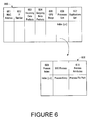
- Host group 600 is used to store the system information described by the Code Sections above. It is appreciated that host group 600 exemplifies a subset of the system information described by the Code Sections above, and that in another embodiment, host group 600 contains system information specified by the RMON MlB of the present embodiment of the present invention.
- the information in host group 600 is periodically transmitted to a central computer system (e.g., edge monitor 300 of Figure 3) at a time interval established by the network manager.
- the information In host group 600 is transmitted to edge monitor 300 when the information changes from a value previously communicated to the edge monitor.
- the information in host group 600 is time-stamped to indicate the time interval corresponding to when the information was collected.
- MAC (Medium Access Control) Address 601 identifies the particular host computer system to the edge monitor.
- IF (Interface) Number 602 identifies the particular segment (e.g., segment 305 of Figure 3) to the central computer system.
- edge monitor 300 can identify the specific host computer system associated with the system information received and catalogued by the edge monitor.
- edge monitor 300 can identify the network segment associated with the system information.
- Incoming data packets 603 represent the number of data packets received by the host computer (e.g., request data packet 290 received by server computer system 250 and response data packet 295 receivcd by client computer system 110 of Figure 2).
- Outgoing data packets 604 represent the number of data packets sent by the host computer (e.g., request data packet 290 sent by client computer system 110 and response data packet 295 sent by server computer system 250).
- CPU (central processing unit) usage 605 represents the amount of computer memory available (e.g., random access memory 102, read-only memory 103, and data storage device 104 of Figure 1), including the total memory available and the amount of memory being used, and thus the remaining memory available.
- computer memory available e.g., random access memory 102, read-only memory 103, and data storage device 104 of Figure 1
- host group 600 of Figure 6 also includes processes list 606 and applications list 607, which provide a compilation of the processes and applications residing in the host computer.
- Host group 600 is not limited to listing only the network processes and network applications.
- Process group 608 includes a tabulation by process index 609 of processes 610 and also includes process attributes 611.
- an analogous application group is referenced by host group 600.
- the present invention enables the network manager to integrally view network performance statistics and system information that correspond to a contemporaneous time period and also correspond to the time that a problem on the communication network occurs.
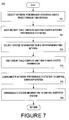
- Figure 7 illustrates a process 700 for collecting network and system information, where process 700 is implemented as program instructions stored in computer-readable memory units of client computer system 110 ( Figure 2) and executed by central processor 101 ( Figure 1), and also stored and executed on server computer system 250 ( Figure 2).
- step 701 of the present embodiment the network performance statistics described above are collected over a predetermined time interval for a client computer system and a server computer system (e.g., client computer system 110 and server computer system 250 of Figure 2) using the method described in the copending patent application filed herewith, assigned to the assignee of the present invention, entitled “Application Response Time and Network Latency Monitoring Using End-Node Computer Systems,” by Richard A. Fletcher and Prakash C. Banthia, with Serial Number , incorporated herewith by reference; and as described in the copending patent application filed herewith, assigned to the assignee of the present invention, entitled “Method for Analyzing Network Application Flows in an Encrypted Environment,” by Richard A. Fletcher and Carl Lin, with Serial Number , also incorporated herewith by reference.
- the network performance statistics are stored in a memory unit (e.g., user history table 560 of Figure 5) of a host computer system (either the client computer system or the server computer system) for each time interval.
- the network performance statistics are time-stamped by the host computer system to indicate the time interval over which the statistics were measured and collected so that historical data can be identified by its collection period. Additional information is provided in the above-named copending patent applications. Additional information is also provided in the copending patent application entitled Title-TBD, Filing Date June 24, 1997, with Serial Number-TBD, 3COM, Attomey Docket Number 9764-93-1.
- step 703 of Figure 7 concurrently with the collection of the network performance statistics, system information is collected by each host computer system regarding its own capabilities and performance.
- client computer system 110 measures and stores system information regarding its capabilities and performance
- server computer system 250 measures and stores system information regarding its capabilities and performance.
- the system performance statistics and system parameters collected by the host computer are as described in the Code Sections above.
- the system information for each host computer system is stored in a memory unit (e.g., host group 600 of Figure 6) of each host computer system for each time interval.
- the system Information is time-stamped by the host computer system to indicate the time interval over which the information was measured and collected so that historical data can be identified by its collection period.
- the network performance statistics are communicated over the communication network to a central computer system (e.g., edge monitor 300 of Figure 3) as described in the concurrent applications referenced above.
- the system information is also communicated over the communication network to edge monitor 300.
- updated system information is communicated to edge monitor 300 at predetermined intervals, e.g., at 30-second intervals, although it is appreciated that other time intervals can be specified in accordance with the present invention.
- system parameters and system performance statistics are communicated to the edge monitor only when a value changes from a value previously communicated to the edge monitor.
- FIG. 8 illustrates a process 800 for collecting network and system information, where process 800 is implemented as program instructions stored in computer-readable memory units of edge monitor 300 ( Figure 3) and executed by central processor 101 ( Figure 1).
- step 801 the network performance statistics determined by client computer system 110 and server computer system 250 and communicated to edge monitor 300 are stored in a memory unit of edge monitor 300.
- the network performance statistics are time-stamped to indicate the time interval over which the statistics were collected.
- the network performance statistics are accumulated and retained in edge monitor 300 for a period of time specified by the network manager.
- historical information and recent updates to the historical information are provided by the network performance data stored in edge monitor 300.
- the system information determined by a host computer system e.g., client computer system 110 or server computer system 250
- the system information is time-stamped to indicate the time interval over which the information was collected.
- the system information is accumulated over time and retained in edge monitor 300 for a period of time specified by the network manager.
- historical information and recent updates to the historical information are provided by the system information data stored in edge monitor 300.
- edge monitor 300 uses the time-stamps to correlate the network performance statistics and the system information collected over concurrent time periods. That is, the network performance statistics corresponding to a particular time interval are correlated to the system information corresponding to a contemporaneous time interval.
- the present invention enables the network manager to integrally view corresponding network performance statistics and system information for a selected time interval, or for the time interval corresponding to the identification of a perturbation in the communication network. Additional information is provided by the copending patent application entitled Title-TBD, Filing Date-TBD, with Serial Number 08/873,440, 3COM, Attorney Docket Number 9764-009500.
- the network and system information provided the present invention also enables the network manager to demonstrate compliance with a governing service level agreement.
- FIG. 3 An example is provided to illustrate the application of the present invention.
- a user of client computer system 110 is experiencing longer response times when running a network application over the communication network.
- the present invention is monitoring application response time (refer to Figure 4) between client computer system 110 and server computer system 250 and reporting the statistical results to edge monitor 300 as described above.
- edge monitor 300 detects that application response time is greater than a predetermined limit and triggers an alarm in order to bring the potential problem to the attention of the network manager.
- the network manager accesses edge monitor 300 to begin an investigation into the slow response time by reviewing network latency statistics (refer to Figure 4) to determine if there is a problem with communication line 240, or with a router or switch (not shown) on that line.
- the network manager accesses the historical network performance data corresponding to the period of time contemporary to the time the perturbation occurred or was identified as indicated by the alarm or by a trouble report. If a problem is not indicated in the network equipment, the network manager is able to use system information corresponding to the same time period (e.g., the period of time contemporary to the time the perturbation occurred or was identified) and stored in edge monitor 300 to review the system information pertaining to client computer system 110 and server computer system 250.
- the network manager might review the remaining amount of memory available or the number of page faults occurring in server computer system 250 in order to determine if the server computer system is "thrashing" because it is being overloaded by other users or by too many large network applications.
- the present invention provides integrated computer system and network monitoring to enable a network manager to integrally evaluate network and system information to readily ascertain the cause of a problem on the communication network.
- the present invention correlates the network and system information according to the time interval over which the information was collected, and the network manager is able to view the correlated information for the time period contemporaneous with the identification of a perturbation in the communication network.
- the present invention provides system information for the host computer systems on a communication network and, in conjunction with the concurrent applications referenced above, the present invention also provides network information.
- the present invention allows the network manager to integrally review both network and system performance data by providing that data in one location.
- the present invention provides access to historical data and recent updates to that data.
- the present invention correlates the network information and system information, so that the network manager is able to review a "snap shot" of the events that were occurring concurrently in the network and in the computer system during the period of time when a perturbation or problem in the communication network is identified.
- the network manager is able to identify whether the source of a problem is with the communication network equipment or with a host computer system on the network. Thus, in aocordance with the present invention, the network manager can then focus on either the communication network or on the computer system, and use the information provided by the present invention to determine the cause of the problem.
- the present invention provides a method to monitor a communication network that enables the network manager to readily detect a problem and determine the cause of the problem. Using the data provided by the present invention, the network manager is also able to demonstrate compliance with a service level agreement.
- the present embodiment of the present invention is implemented using an extension to an RMON MIB and is therefore compatible with SNMP protocol.
Abstract
Description
- The present invention relates to the field of computer system communication networks. In particular, the present invention pertains to computer system and network monitoring and management.
- Computer systems linked to each other in a communication network are commonly used in businesses and like organizations. Computer system communication networks ("networks") are growing in size - as measured by the number of applications and the number of users they support - due to improvements in network reliability and the recognition of associated benefits such as increased productivity.
- As the size of networks increases and as organizations become more reliant on such networks, the importance of effective network management tools also grows. In response to the need for standardization of such tools, primarily to control costs but also because components in a network are likely to originate from many different vendors, the Simple Network Management Protocol (SNMP) was developed and widely adopted. There have been a number of management information bases (MlBs) defined since adoption of SNMP, such as MlS-II, Remote Network Monitoring (RMON), and RMON2.
- SNMP, RMON and RMON2 thus are network management software tools that provide a set of standards for network management and control, including a standard protocol, a specification for database structure, and a set of data objects. RMON and RMON2 are implemented in a network through MlBs which contain instructions specifying the data that are to be collected, how the data are to be identified, and other information pertinent to the purpose of network monitoring. In the prior art, the MlBs are implemented through RMON probes to monitor the local areas of the network. (An RMON probe typically is a computer system strategically located within the network so as to monitor a local area of the network.) The network monitoring information obtained by the RMON probes is communicated to a central computer system that is accessible by the network manager.
- Prior art network monitoring and management tools have trouble aiding the network manager in determining whether a problem within the network is associated with the network equipment itself or with the computer systems coupled to the network. If this information were known, it would allow the network manager to identify and implement the appropriate corrective action. For example, if a user places a request for a particular application from a client computer system to a server computer system and a response is delayed or is not received, the prior art network management tools do not give the network manager enough information to identify whether the problem is occurring because of a bottleneck in the network equipment or because the client or server computer system is not functioning properly.
- Effective network monitoring and management tools are also needed in order for vendors of network management services to demonstrate compliance with the governing service level agreement (SLA). Many businesses contract with vendors for network management services. Such contracts are typically implemented with SLAs which specify metrics against which the provider of the network management services is measured. These metrics are used to quantify standards of performance that allow businesses to assess not only the performance of the network but also the performance of the network management services provider. Prior art network management tools generally do not provide effective means for monitoring the network and facilitating compliance with the requirements contained in the SLAs.
- The prior art network monitoring and management tools are problematic because they do not provide the network manager with sufficient and readily accessible information enabling him/her to quickly pinpoint the source of a problem and solve it. In the prior art, the network manager must look at various sources of information, typically beginning with available network information from the RMON probes, to try to identify the cause of a problem. Once the network manager reviews the network information available, only then may he or she conclude that the problem is not with the network equipment but with a server or client computer system on the network. At this point, the network manager (or an equivalent system manager) begins a lengthy process of researching potential causes from the system perspective. While there may be some degree of manual coordination of the network and system efforts to identify the cause of a problem, the network tools in the prior art are not capable of automatically facilitating a coordinated effort to an extent that is optimum. Thus, in the prior art it is not possible to quickly and automatically pinpoint a problem as either a network problem or a system problem.
- Timely correction of problems on a network is essential, because of the effect on user productivity and the desire for fast service that is prevalent among users. Service level agreements also place a premium on timely resolution of network problems. Thus, the prior art techniques for monitoring networks and identifying problems and their causes are not responsive to the requirements of the users and the business served by the network. The prior art techniques are also not responsive to the needs of the network and/or system managers who are charged with accomplishing timely identification and resolution of problems.
- Another disadvantage to the prior art is that the RMON probes are capable only of monitoring network performance. The RMON probes cannot monitor the performance of client and server computer systems and communicate information about system performance to the central computer system used by the network manager. Therefore, in the prior art, the monitoring tools do not provide information about system performance.
- In one prior art system, a server computer system and a client computer system send messages, commonly referred to as "heartbeats," to each other to affirm that a connection exists and that both computer systems are functioning. However, the heartbeats only communicate between the lower levels of software in the computer systems (e.g., between the protocol stacks), and so do not provide an indication of a possible problem at the higher levels of software, such as "memory thrashing" in the central processor unit of a computer system. Hence, a computer system may in fact be experiencing a problem that would not be detectable in the prior art, and the network/system manager may conclude based on the information available that the computer system Is functioning satisfactorily.
- Another drawback to the prior art is that the limited network and system information that is available to the network manager is not historical; that is, information regarding the recent performance of the network and system preceding the occurrence of a problem is not retrievable by the network manager. As such, the network manager can only view network or system performance after a user has identified a problem. Thus, in the prior art, valuable historical information that may aid the network manager in understanding the source of a problem is not available.
- Thus, a need exists for a method to monitor a computer system communication network that readily detects a problem and permits the network manager to quickly identify the cause of the problem. A need further exists for a method that accomplishes the above and enables the network manager to demonstrate compliance with the provisions of the governing SLA. A need yet exists for a method that accomplishes the above and is compatible with the SNMP protocol that is currently employed. The present invention solves these needs. These and other objects and advantages of the present invention will become obvious to those of ordinary skill in the art after having read the following detailed description of the preferred embodiments which are illustrated in the various drawing figures.
- The present invention provides a method to monitor a computer system communication network that readily detects a problem and permits the network manager to quickly identify the cause of the problem. The present invention also provides a method that accomplishes the above and enables the network manager to demonstrate compliance with the provisions of the governing service level agreement (SLA). Finally, the present invention provides a method that accomplishes the above and is cost-effective and compatible with the Simple Network Management Protocol that is currently employed in many communication networks.
- The present invention described herein provides a method for quantifying communication performance in a communication network having computer systems communicatively coupled to each other with communication equipment. In one embodiment, a computer system of a communication network measures and time-stamps network performance statistics and stores them in a memory unit within the computer system. The computer system also measures and time-stamps system performance statistics and system parameters and stores them in the memory unit within the computer system. The computer system reports the network performance statistics and the system information to a central computer system at specified time intervals. The central computer system correlates the network performance statistics and the system information for a specified time period based on the time-stamps. The central computer system displays the correlated network performance statistics and system information to a user in response to the identification of a perturbation in the communication network, where the correlated network performance statistics and system Information are displayed for a time interval contemporaneous with the perturbation, so that the user can integrally analyze the information.
- In one embodiment, the method provided by the present invention and described above is implemented using a management information base (MlB) extension to Remote Network Monitoring (RMON)-based software, where the RMON MIB specifies the system information to be measured and stored.
- The accompanying drawings, which are incorporated in and form a part of this specification, illustrate embodiments of the invention and, together with the description, serve to explain the principles of the invention:
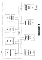
- FIGURE 1 shows a general purpose computer system upon which embodiments of the present invention may be practiced.
- FIGURE 2 is a diagram of an exemplary computer system communication network upon which the present invention may be practiced.
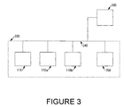
- FIGURE 3 is a diagram of a segment of an exemplary computer system communication network upon which the present invention may be practiced.
- FIGURE 4 is a diagram defining network performance statistics for an exemplary computer system communication network upon which the present invention may be practiced.
- FIGURE 5 is an Illustration of a network performance statistics data table in accordance with one embodiment of the present invention.
- FIGURE 6 is an illustration of a system Information host group in accordance with one embodiment of the present invention.
- FIGURE 7 is a flow chart of a process for collecting network performance statistics and system information in accordance with one embodiment of the present invention.
- FIGURE 8 is a flow chart of a process for correlating network performance statistics and system information in accordance with one embodiment of the present invention.
-
- Reference will now be made in detail to the preferred embodiments of the invention, examples of which are illustrated in the accompanying drawings. While the invention is described in conjunction with the preferred embodiments, it is understood that they are not intended to limit the invention to these embodiments. On the contrary, the invention is intended to cover alternatives, modifications and equivalents, which may be included within the spirit and scope of the Invention as defined by the appended claims. Furthermore, in the following detailed description of the present invention, numerous specific details are set forth in order to provide a thorough understanding of the present invention. However, it will be obvious to one of ordinary skill in the art that the present invention may be practiced without these specific details. In other instances, well-known methods, procedures, components, and circuits have not been described in detail so as not to unnecessarily obscure aspects of the present invention.
- Some portions of the detailed descriptions which follow are presented in terms of procedures, logic blocks, processing, and other symbolic representations of operations on data bits within a computer memory. These descriptions and representations are the means used by those skilled in the data processing arts to most effectively convey the substance of their work to others skilled in the art. A procedure, logic block, process, etc., is here, and generally, conceived to be a self-consistent sequence of steps or instructions leading to a desired result. The steps are those requiring physical manipulations of physical quantities. Usually, though not necessarily, these quantities take the form of electrical or magnetic signals capable of being stored, transferred, combined, compared, and otherwise manipulated in a computer system. It has proven convenient at times, principally for reasons of common usage, to refer to these signals as bits, bytes, values, elements, symbols, characters, terms, numbers, or the like.
- It should be bome in mind, however, that all of these and similar terms are to be associated with the appropriate physical quantities and are merely convenient labels applied to these quantities. Unless specifically stated otherwise as apparent from the following discussions, it is appreciated that throughout the present invention, discussions utilizing terms such as "processing" or "computing" or "calculating" or "determining" or "displaying" or the like, refer to the action and processes of a computer system (e.g., processes of Figures 7 and 8), or similar electronic computing device, that manipulates and transforms data represented as physical (electronic) quantities within the computer system's registers and memories into other data similarly represented as physical quantities within the computer system memories or registers or other such information storage, transmission or display devices.
- Refer to Figure 1 which illustrates a host computer system, client computer system 110 (the following discussion is also pertinent to a server computer system and a central computer system). In general,
client computer system 110 used by the embodiments of the present invention comprises abus 100 for communicating information, acentral processor 101 coupled withbus 100 for processing information and instructions, arandom access memory 102 coupled withbus 100 for storing Information and Instructions forcentral processor 101, a read-only memory 103 coupled withbus 100 for storing static information and instructions forcentral processor 101, adata storage device 104 such as a magnetic or optical disk and disk drive coupled withbus 100 for storing information and instructions, adisplay device 105 coupled tobus 100 for displaying information to the computer user, an optionalalphanumeric input device 106 including alphanumeric and function keys coupled tobus 100 for communicating Information and command selections tocentral processor 101, an optionalcursor control device 107 coupled tobus 100 for communicating user input information and command selections tocentral processor 101, and a network interface card (NIC) 108 coupled tobus 100 for communicating from a communication network tocentral processor 101. -
Display device 105 of Figure 1 utilized withclient computer system 110 of the present invention may be a liquid crystal device, cathode ray tube, or other display device suitable for creating graphic images and alphanumeric characters recognizable to the user.Cursor control device 107 allows the computer user to dynamically signal the two-dimensional movement of a visible symbol (pointer) on a display screen ofdisplay device 105. Many implementations of the cursor control device are known in the art including a trackball, mouse, joystick or special keys onalphanumeric input device 106 capable of signaling movement of a given direction or manner of displacement. It is to be appreciated that the cursor means 107 also may be directed and/or activated via input from the keyboard using special keys and key sequence commands. Alternatively, the cursor may be directed and/or activated via input from a number of specially adapted cursor directing devices. - With reference now to Figure 2, a diagram showing
client computer system 110 coupled toserver computer system 250 incommunication network 205 is provided. In a typical communication network, there are a plurality of host computer systems, e.g., client computer systems and server computer systems, that are coupled to each other with communications equipment. For the discussion herein, a singleclient computer system 110 is shown coupled viacommunications lines server computer system 250, but more computer systems could be employed. - With reference still to Figure 2, the software executed by central processor 101 (Figure 1) of
client computer system 110 is represented byapplication layer 210 which is separated from the remainder ofprotocol stack 220.Application layer 210 defines the manner in which network applications interact with the communication network, where network applications include computer software programs, word processors, database management systems, electronic mail, and the like.Protocol stack 220 contains the remaining layers of software that define the computer-to-computer or computer-to-network protocol, where protocol defines the procedures to be followed when data are transmitted and received. In a similar manner,server computer system 250 includesapplication layer 260 andprotocol stack 270. - Continuing with reference to Figure 2, one of the software layers (e.g., application layer 210) of
client computer system 110 transmits a request toserver computer system 250 in the form ofrequest data packet 290, andserver computer system 250 responds to the request in the form ofresponse data packet 295. In this example,request data packet 290 andresponse data packet 295 are shown traveling by different communications lines (e.g., In a switched network environment), but it is appreciated that in the present invention the data packets alternatively can travel over the same communications line. - Figure 3 shows
segment 305 of a communication network including host computer systems exemplified byclient computer systems server computer system 250, andcentral computer system 300 that is alternatively referred to as an "edge monitor." A communication network typically includes communicatively coupled switches, routers and additional segments (not shown).Edge monitor 300 receives information from multiple network segments. - The present invention includes a method for monitoring communication performance in a communication network such as that exemplified by Figure 3. In accordance with the present invention, a host computer system (e.g.,
client computer system 110 or server computer system 250) measures and stores network performance statistics. The host computer system also measures and stores historical information Including system information consisting of system performance statistics and system parameters. In the present invention, the network and system information are communicated to a central computer system (e.g., edge monitor 300), where the information is stored and catalogued in a manner that identifies the host computer system providing the information and the time period over which the information was measured by the host computer system. In accordance with the present invention, the network and system information is correlated so that it can be integrally analyzed. Based on the analysis, the present invention thus permits the network manager to make conclusions regarding the performance of the communication network and the cause of a network problem. - With reference now to Figure 4,
client computer system 110 is coupled toserver computer system 250 in a communication network (e.g.,communication network 205 of Figure 2). A data packet takes a measurable amount of time to travel fromclient computer system 110 toserver computer system 250, and vice versa. It also takes a measurable amount of time for a computer system to perform an application. - Continuing with reference to Figure 4, "protocol latency" is the amount of time for a data packet to travel one-way through a protocol stack of a computer system. Hence, protocol latency is the amount of time for a data packet to travel from point A to point B or from point B to point A in
protocol stack 220, or from point D to point E or point E to point D inprotocol stack 270. - With reference to Figure 4, "application processing time" is the time required for
server computer system 250 to complete performing a network application in response to a request received fromclient computer system 110. In one embodiment of the present invention, application processing time is the elapsed time period between the time whenrequest data packet 290 entersapplication layer 260 ofserver computer system 250 and the time when the correspondingresponse data packet 295exits application layer 260 of server computer system 250 (one-way from point D to point D'). In another embodiment, application processing time is the period from the time when the application program interface ofserver computer system 250 issues a receive socket call corresponding to requestdata packet 290 to the time when the application program interface ofserver computer system 250 issues a send socket call corresponding toresponse data packet 295. - With reference still to Figure 4, in one embodiment of the present invention, "application response time" is the elapsed time period between the time when
request data packet 290exits application layer 210 ofclient computer system 110 and the time whenresponse data packet 295 entersapplication layer 210 of client computer system 110 (round trip from point A to point C), whereresponse data packet 295 is sent in response to requestdata packet 290. In another embodiment, application response time is the time period between when the application program interface ofclient computer system 110 generates a send socket call corresponding to requestdata packet 290 and a receive socket call corresponding to receivesocket call 295. - With reference to Figure 4, "network latency" is the amount of time required for the data packet to travel from point B at which it exits one computer system to point E at which it enters another computer system, e.g., the time to travel one-way from
network interface card 108 inclient computer system 110 of Figure 1, to the network interface card inserver computer system 250, and vice versa. - The network performance statistics named above are determined as described In the copending patent application filed concurrently herewith and assigned to the assignee of the present invention, entitled "Application Response Time and Network Latency Monitoring Using End-Node Computer Systems," by Richard A. Fletcher and Prakash C. Banthia, with Serial Number ; and as described in the copending patent application filed concurrently herewith, assigned to the assignee of the present invention, entitled "Method for Analyzing Network Application Flows in an Encrypted Environment," by Richard A. Fletcher and Carl Lin, with Serial Number , both of which are hereby incorporated by reference.
- As described by the copending patent applications named above, in one embodiment the network performance statistics are determined using time-stamps that are applied by the client and server computer systems (e.g.,
client computer system 110 andserver computer system 250 of Figure 2) to the request and response data packets (e.g.,request data packet 290 andresponse data packet 295 of Figure 2). In another embodiment, the network performance statistics are determined using time-stamps that are applied byclient computer system 110 andserver computer system 250 to the socket calls that are issued by the application program interface corresponding to requestdata packet 290 andresponse data packet 295. As described in the copending patent applications referenced above, the difference between two time-stamps is used to measure the time for a data packet to travel from one of the points designated in Figure 4 to another designated point. - Refer now to Figure 5, which illustrates the memory structure of the present embodiment of the present invention within the computer-readable memory units of
client computer system 110 and also inserver computer system 250 of Figure 2. In one embodiment, data table 540 is used to store entries consisting of the time difference between time-stamps. In one embodiment, data table 540 is alternatively referred to as a response time buffer. - In the present embodiment, statistics table 550 is used to store performance statistics that are based on the information stored in data table 540 or in a response time buffer. At a time interval specified by the network manager, the performance statistics in statistics table 550 are read to user-history table 560. In the present embodiment, statistics table 550 accumulates the minimum, maximum, average and median for the entries stored in data table 540. The information stored in statistics table 550 is collected for a specified time interval, and then read to user-history table 560. In user-history table 560, a set of data are stored for each of a plurality of time intervals. The set of data stored for each time interval may also be combined to compute data for a longer time interval. The data stored in user-history table 560 are time-stamped to indicate the time interval corresponding to each set of data. Thus, the data can be sorted according to the time interval during which it was collected.
- At a time interval specified by the network manager, the data stored in user-history table 560 are read to a central computer system (e.g., central computer system, or edge monitor, 300 of Figure 3).
- In addition to the network performance statistics described above, system information consisting of system performance statistics and system parameters are measured by a host computer system and communicated to a central computer system in accordance with the present invention.
- In the present embodiment of the present invention, "system performance statistics" generally describe dynamic data collected by a host computer system (e.g.,
client computer system 110 orserver computer system 250 of Figure 2) regarding its own performance. For example, system performance statistics include the number of errors or the number of page faults that occur for a computer system during a time interval specified by the network manager. System performance statistics are periodically communicated to a central computer system (e.g., edge monitor 300 of Figure 3) at a time interval specified by the network manager. System performance statistics collected in one embodiment of the present invention are described in the Code Sections below. In alternative embodiments, additional system performance statistics are specified. - In the present embodiment, "system parameters" generally describe static information or information that does not frequently change that is collected by a host computer system (e.g.,
client computer system 110 or server computer system 250) regarding its own hardware and software capabilities. For example, system parameters include the quantity of memory available in a data storage device of a host computer system (e.g.,data storage device 104 of Figure 1) or the quantity of random access memory available in a computer system (e.g.,random access memory 102 of Figure 1). System parameters also describe the number of applications or the number of processes residing in a computer system. In one embodiment, system parameters are periodically communicated to a central computer system (e.g., edge monitor 300 of Figure 3) at a time interval specified by the network manager. In one embodiment, system parameters are only communicated to a central computer system when they change from a value previously reported to the central computer system. System parameters collected in one embodiment of the present invention are described in the Code Sections below. In alternative embodiments, additional system parameters are specified. - In the present embodiment, the present invention uses an extension to an RMON MlB to implement the method and architecture for specifying and collecting the system information (system performance statistics and system parameters) to be measured. As previously discussed, RMON is a supplement to the SNMP protocol currently employed in computer system communication networks, and thus the present embodiment of the present invention is compatible with the standards currently in use. In the present embodiment, the RMON MIB is implemented in the client and server computer systems in accordance with the application Title-TBD, Filing Date June 24, 1997, Serial Number-TBD, 3COM, Attorney Docket Number 9764-93-1, which is hereby incorporated by reference. Hence, the present embodiment of the present invention does not require additional hardware and so provides a cost-effective method for monitoring network and system performance.
- The RMON MlB specified in accordance with the present embodiment is described in the Code Sections below.


- The Description Group of the RMON MIB specified in accordance with the present embodiment is described in the Code Section below. The Description Group lists the inventory of the computer system and includes a description table, a processor table, and an input/output bus table.


- The User Group of the RMON MIB specified in accordance with the present embodiment is described in the Code Section below. The User Group provides a table listing information regarding user sessions.

- The Central Processing Unit (CPU) Group of the RMON MlB specified in accordance with the present embodiment is described in the Code Section below. The CPU Group includes a table showing CPU usage.

- The Memory Group of the RMON MlB specified in accordance with the present embodiment is described in the Code Section below. The Memory Group provides a table that shows memory properties such as the available memory in a data storage device and in a random access memory unit.


- The Drive Group of the RMON MIB specified in accordance with the present embodiments is described in the Code Section below. The Drive Group provides information regarding the hard disk performance, drive properties, and drive controller properties, and includes a hard disk table, a drive table, and a drive controller table.


- The Application Group of the RMON MIB specified in accordance with the present embodiment is described In the Code Section below. The Application Group provides a summary of applications residing on the computer system and lists the application properties, and includes an applications summary table and an application table.


- The Process Group of the RMON MIB specified in accordance with the present embodiment is described in the Code Section below. The Process Group provides a summary of the processes utilized by the computer system and lists the process properties, and includes a process summary table and a process table.


 The Error Group of the RMON MIB specified in accordance with the present embodiment is described in the Code Section below. The Error Group lists a summary of errors and error properties, and includes an error summary table and an error table.


- Refer now to Figure 6, which Illustrates the memory structure within the computer-readable memory units of
client computer system 110 and also inserver computer system 250 of Figure 2 in one embodiment of the present invention.Host group 600 is used to store the system information described by the Code Sections above. It is appreciated thathost group 600 exemplifies a subset of the system information described by the Code Sections above, and that in another embodiment,host group 600 contains system information specified by the RMON MlB of the present embodiment of the present invention. - In one embodiment, the information in
host group 600 is periodically transmitted to a central computer system (e.g., edge monitor 300 of Figure 3) at a time interval established by the network manager. In one embodiment, the information Inhost group 600 is transmitted to edge monitor 300 when the information changes from a value previously communicated to the edge monitor. The information inhost group 600 is time-stamped to indicate the time interval corresponding to when the information was collected. - With reference to Figure 6, MAC (Medium Access Control)
Address 601 identifies the particular host computer system to the edge monitor. IF (Interface)Number 602 identifies the particular segment (e.g.,segment 305 of Figure 3) to the central computer system. In this manner, edge monitor 300 can identify the specific host computer system associated with the system information received and catalogued by the edge monitor. In addition, edge monitor 300 can identify the network segment associated with the system information. - Continuing with reference to Figure 6, other information stored in
host group 600 in one embodiment is exemplified.Incoming data packets 603 represent the number of data packets received by the host computer (e.g.,request data packet 290 received byserver computer system 250 andresponse data packet 295 receivcd byclient computer system 110 of Figure 2).Outgoing data packets 604 represent the number of data packets sent by the host computer (e.g.,request data packet 290 sent byclient computer system 110 andresponse data packet 295 sent by server computer system 250). CPU (central processing unit)usage 605 represents the amount of computer memory available (e.g.,random access memory 102, read-only memory 103, anddata storage device 104 of Figure 1), including the total memory available and the amount of memory being used, and thus the remaining memory available. - In one embodiment,
host group 600 of Figure 6 also includesprocesses list 606 andapplications list 607, which provide a compilation of the processes and applications residing in the host computer.Host group 600 is not limited to listing only the network processes and network applications. Using processes list 606 as an example in Figure 6, the processes residing in the host computer are referenced to processgroup 608 byprocess index 609.Process group 608 includes a tabulation byprocess index 609 ofprocesses 610 and also includes process attributes 611. In this embodiment, an analogous application group is referenced byhost group 600. - The present invention enables the network manager to integrally view network performance statistics and system information that correspond to a contemporaneous time period and also correspond to the time that a problem on the communication network occurs.
- Figure 7 illustrates a
process 700 for collecting network and system information, whereprocess 700 is implemented as program instructions stored in computer-readable memory units of client computer system 110 (Figure 2) and executed by central processor 101 (Figure 1), and also stored and executed on server computer system 250 (Figure 2). - With reference to Figure 7, in
step 701 of the present embodiment, the network performance statistics described above are collected over a predetermined time interval for a client computer system and a server computer system (e.g.,client computer system 110 andserver computer system 250 of Figure 2) using the method described in the copending patent application filed herewith, assigned to the assignee of the present invention, entitled "Application Response Time and Network Latency Monitoring Using End-Node Computer Systems," by Richard A. Fletcher and Prakash C. Banthia, with Serial Number , incorporated herewith by reference; and as described in the copending patent application filed herewith, assigned to the assignee of the present invention, entitled "Method for Analyzing Network Application Flows in an Encrypted Environment," by Richard A. Fletcher and Carl Lin, with Serial Number , also incorporated herewith by reference. - In
step 702 of Figure 7, in the present embodiment, the network performance statistics are stored in a memory unit (e.g., user history table 560 of Figure 5) of a host computer system (either the client computer system or the server computer system) for each time interval. In the present embodiment, the network performance statistics are time-stamped by the host computer system to indicate the time interval over which the statistics were measured and collected so that historical data can be identified by its collection period. Additional information is provided in the above-named copending patent applications. Additional information is also provided in the copending patent application entitled Title-TBD, Filing Date June 24, 1997, with Serial Number-TBD, 3COM, Attomey Docket Number 9764-93-1. - In
step 703 of Figure 7, concurrently with the collection of the network performance statistics, system information is collected by each host computer system regarding its own capabilities and performance. In other words,client computer system 110 measures and stores system information regarding its capabilities and performance, andserver computer system 250 measures and stores system information regarding its capabilities and performance. In the present embodiment, the system performance statistics and system parameters collected by the host computer are as described in the Code Sections above. - In
step 704 of Figure 7, in the present embodiment, the system information for each host computer system is stored in a memory unit (e.g.,host group 600 of Figure 6) of each host computer system for each time interval. In the present embodiment, the system Information is time-stamped by the host computer system to indicate the time interval over which the information was measured and collected so that historical data can be identified by its collection period. - In
step 705 of Figure 7, the network performance statistics are communicated over the communication network to a central computer system (e.g., edge monitor 300 of Figure 3) as described in the concurrent applications referenced above. Instep 706, the system information is also communicated over the communication network to edgemonitor 300. In one embodiment, updated system information is communicated to edge monitor 300 at predetermined intervals, e.g., at 30-second intervals, although it is appreciated that other time intervals can be specified in accordance with the present invention. In an alternative embodiment, system parameters and system performance statistics are communicated to the edge monitor only when a value changes from a value previously communicated to the edge monitor. - Figure 8 illustrates a
process 800 for collecting network and system information, whereprocess 800 is implemented as program instructions stored in computer-readable memory units of edge monitor 300 (Figure 3) and executed by central processor 101 (Figure 1). Instep 801, the network performance statistics determined byclient computer system 110 andserver computer system 250 and communicated to edge monitor 300 are stored in a memory unit ofedge monitor 300. As noted above, the network performance statistics are time-stamped to indicate the time interval over which the statistics were collected. The network performance statistics are accumulated and retained in edge monitor 300 for a period of time specified by the network manager. Thus, in the present embodiment, historical information and recent updates to the historical information are provided by the network performance data stored inedge monitor 300. - In
step 802 of Figure 8, the system information determined by a host computer system (e.g.,client computer system 110 or server computer system 250) and communicated to edge monitor 300 are stored in a memory unit of the edge monitor. As noted above, the system information is time-stamped to indicate the time interval over which the information was collected. The system information is accumulated over time and retained in edge monitor 300 for a period of time specified by the network manager. Thus, in the present embodiment, historical information and recent updates to the historical information are provided by the system information data stored inedge monitor 300. - In
step 803 of Figure 8, in the present embodiment, edge monitor 300 uses the time-stamps to correlate the network performance statistics and the system information collected over concurrent time periods. That is, the network performance statistics corresponding to a particular time interval are correlated to the system information corresponding to a contemporaneous time interval. In this manner, the present invention enables the network manager to integrally view corresponding network performance statistics and system information for a selected time interval, or for the time interval corresponding to the identification of a perturbation in the communication network. Additional information is provided by the copending patent application entitled Title-TBD, Filing Date-TBD, with Serial Number 08/873,440, 3COM, Attorney Docket Number 9764-009500. The network and system information provided the present invention also enables the network manager to demonstrate compliance with a governing service level agreement. - With reference back to Figure 3, an example is provided to illustrate the application of the present invention. A user of
client computer system 110 is experiencing longer response times when running a network application over the communication network. In one embodiment, the present invention is monitoring application response time (refer to Figure 4) betweenclient computer system 110 andserver computer system 250 and reporting the statistical results to edge monitor 300 as described above. In this embodiment, edge monitor 300 detects that application response time is greater than a predetermined limit and triggers an alarm in order to bring the potential problem to the attention of the network manager. - Continuing with the example, in response to the alarm, the network manager accesses edge monitor 300 to begin an investigation into the slow response time by reviewing network latency statistics (refer to Figure 4) to determine if there is a problem with
communication line 240, or with a router or switch (not shown) on that line. The network manager accesses the historical network performance data corresponding to the period of time contemporary to the time the perturbation occurred or was identified as indicated by the alarm or by a trouble report. If a problem is not indicated in the network equipment, the network manager is able to use system information corresponding to the same time period (e.g., the period of time contemporary to the time the perturbation occurred or was identified) and stored in edge monitor 300 to review the system information pertaining toclient computer system 110 andserver computer system 250. For example, the network manager might review the remaining amount of memory available or the number of page faults occurring inserver computer system 250 in order to determine if the server computer system is "thrashing" because it is being overloaded by other users or by too many large network applications. Hence, in this manner the present invention provides integrated computer system and network monitoring to enable a network manager to integrally evaluate network and system information to readily ascertain the cause of a problem on the communication network. The present invention correlates the network and system information according to the time interval over which the information was collected, and the network manager is able to view the correlated information for the time period contemporaneous with the identification of a perturbation in the communication network. - In summary, the present invention provides system information for the host computer systems on a communication network and, in conjunction with the concurrent applications referenced above, the present invention also provides network information. The present invention allows the network manager to integrally review both network and system performance data by providing that data in one location. The present invention provides access to historical data and recent updates to that data. Using the time-stamps applied to the data, the present invention correlates the network information and system information, so that the network manager is able to review a "snap shot" of the events that were occurring concurrently in the network and in the computer system during the period of time when a perturbation or problem in the communication network is identified. Based on the information provided using the present invention, the network manager is able to identify whether the source of a problem is with the communication network equipment or with a host computer system on the network. Thus, in aocordance with the present invention, the network manager can then focus on either the communication network or on the computer system, and use the information provided by the present invention to determine the cause of the problem.
- The present invention provides a method to monitor a communication network that enables the network manager to readily detect a problem and determine the cause of the problem. Using the data provided by the present invention, the network manager is also able to demonstrate compliance with a service level agreement. The present embodiment of the present invention is implemented using an extension to an RMON MIB and is therefore compatible with SNMP protocol.
- The preferred embodiment of the present invention, integrated computer system and network performance monitoring, is thus described. While the present invention has been described in particular embodiments, it should be appreciated that the present invention should not be construed as limited by such embodiments, but rather construed according to the following claims.
Claims (25)
- In a communication network comprising computer systems communicatively coupled with communication equipment, a method for monitoring communication performance comprising the steps of:a) a computer system measuring and time-stamping network performance statistics and storing said network performance statistics in a memory unit of said computer system;b) said computer system measuring and time-stamping system information and storing said system information in said memory unit of said computer system, wherein said system information recites system performance statistics and system parameters of said computer system, wherein said steps a) and b) are performed concurrently;c) said computer system reporting said network performance statistics and said system information to a central computer system at specified time intervals, wherein said network performance statistics and said system information are indexed to said computer system; andd) said central computer system correlating network performance statistics measured during a specified time interval with system information measured during said specified time interval based on said time-stamping and storing said network performance statistics and said system information in a memory unit of said central computer system.
- The method as recited in Claim 1 further comprising the step of:
e) said central computer system displaying correlated network performance statistics and system information in response to identification of a perturbation in said communication network, wherein said correlated network performance statistics and system information are displayed for a time interval contemporaneous with said perturbation. - The method as recited in Claim 1 wherein said computer system is a client computer system.
- The method as recited in Claim 1 wherein said computer system is a server computer system.
- The method as recited in Claim 1 wherein step a) further comprises measuring application response time.
- The method as recited in Claim 1 wherein step a) further comprises measuring application processing time.
- The method as recited in Claim 1 wherein step a) further comprises measuring network latency.
- The method as recited in Claim 1 wherein step a) further comprises measuring protocol latency.
- The method as recited in Claim 1 wherein step b) is implemented using a management information base extension to Remote Network Monitoring (RMON)-based computer software, said management information base extension specifying said system information.
- The method as recited in Claim 1 wherein step b) further comprises measuring page faults by said computer system.
- The method as recited in Claim 1 wherein step b) further comprises measuring errors by said computer system.
- The method as recited in Claim 1 wherein step b) further comprises measuring hardware capabilities of said computer system.
- The method as recited in Claim 12 further comprising the step of quantifying available memory in a data storage device of said computer system.
- The method as recited in Claim 12 further comprising the step of quantifying available memory in a random access memory unit of said computer system.
- The method as recited in Claim 1 wherein step b) further comprises identifying network applications utilized by said computer system.
- The method as recited in Claim 1 wherein step b) further comprises identifying processes utilized by said computer system.
- A computer system comprising:a processor coupled to a bus; anda memory unit coupled to said bus and having stored therein instructions that when executed by said processor implement a method for monitoring communication performance of a communication network comprising computer systems communicatively coupled to each other, said method comprising the steps of:a) measuring and time-stamping network performance statistics and storing said network performance statistics in said memory unit of said computer system;b) measuring and time-stamping system information and storing said system information in said memory unit of said computer system, wherein said system information recites system performance statistics and system parameters of said computer system, wherein said steps a) and b) are performed concurrently; andc) reporting said network performance statistics and said system information to a central computer system at specified time intervals, wherein said network performance statistics and said system information are indexed to said computer system; whereind) said central computer system correlates network performance statistics measured during a specified time interval with system information measured during said specified time interval based on said time-stamping and storing said network perfomance statistics and said system information in a memory unit of said central computer system.
- The computer system as described in Claim 17 wherein said computer system is a client computer system.
- The computer system as described in Claim 17 wherein said computer system is a server computer system.
- The computer system as described in Claim 17 wherein said network performance statistics measure application response time, application processing time, network latency and protocol latency.
- The computer system as described in Claim 17 wherein said system information is specified in a management information base extension to Remote Network Monitoring (RMON)-based computer software.
- The computer system as described in Claim 17 wherein said system performance statistics measure page faults and errors by said computer system.
- The computer system as described in Claim 17 wherein said system parameters measure hardware capabilities of said computer system.
- The computer system as described in Claim 17 wherein said system parameters identify network applications and processes utilized by said computer system.
- In a communication network comprising computer systems communicatively coupled with communication equipment, a method for monitoring communication performance comprising the steps of:a) a computer system measuring and time-stamping network performance statistics and storing said network performance statistics in a memory unit of said computer system;b) said computer system measuring and time-stamping system information and storing said system information in said memory unit of said computer system, wherein said system information is specified by a management information base extension to Remote Network Monitoring (RMON)-based computer software, wherein said steps a) and b) are performed concurrently;c) said computer system reporting said network performance statistics and said system information to a central computer system at specified time intervals, wherein said network performance statistics and said system information are indexed to said computer system;d) said central computer system correlating network performance statistics measured during a specified time interval with system information measured during said specified time interval based on said time-stamping and storing said network performance statistics and said system information in a memory unit of said central computer system; ande) said central computer system displaying correlated network performance statistics and system information in response to identification of a perturbation in said communication network, wherein said correlated network performance statistics and system information are displayed for a time interval contemporaneous with said perturbation.
Applications Claiming Priority (2)
| Application Number | Priority Date | Filing Date | Title |
|---|---|---|---|
| US09/143,486 US6269401B1 (en) | 1998-08-28 | 1998-08-28 | Integrated computer system and network performance monitoring |
| US143486 | 1998-08-28 |
Publications (3)
| Publication Number | Publication Date |
|---|---|
| EP0994602A2 true EP0994602A2 (en) | 2000-04-19 |
| EP0994602A3 EP0994602A3 (en) | 2002-04-24 |
| EP0994602B1 EP0994602B1 (en) | 2005-06-01 |
Family
ID=22504297
Family Applications (1)
| Application Number | Title | Priority Date | Filing Date |
|---|---|---|---|
| EP99306854A Expired - Lifetime EP0994602B1 (en) | 1998-08-28 | 1999-08-27 | Computer system and network performance monitoring |
Country Status (4)
| Country | Link |
|---|---|
| US (1) | US6269401B1 (en) |
| EP (1) | EP0994602B1 (en) |
| AT (1) | ATE297087T1 (en) |
| DE (1) | DE69925557T2 (en) |
Cited By (9)
| Publication number | Priority date | Publication date | Assignee | Title |
|---|---|---|---|---|
| WO2001031539A1 (en) * | 1999-10-27 | 2001-05-03 | Market Data Systems, Inc. | Analysis and reporting of time dependent business performance data |
| WO2001097553A2 (en) * | 2000-06-15 | 2001-12-20 | Telefonaktiebolaget L M Ericsson (Publ) | Method and apparatus for obtaining measurement data for performance analysis in a radio network |
| EP1195947A2 (en) * | 2000-10-04 | 2002-04-10 | Nec Corporation | Network monitoring control system and method |
| EP1223695A2 (en) * | 2001-01-13 | 2002-07-17 | Philips Corporate Intellectual Property GmbH | Transponder for monitoring network elements in hybrid fiber/coax networks |
| EP1456982A1 (en) * | 2001-11-09 | 2004-09-15 | ADC DSL Systems, Inc. | Non-chronological system statistics |
| WO2005043818A1 (en) * | 2003-10-30 | 2005-05-12 | Telkom Sa Limited | A communications network test system |
| US7325037B2 (en) | 2002-02-27 | 2008-01-29 | Eastman Kodak Company | Method and system for client-based adaptive networking system |
| CN101584185B (en) * | 2007-01-24 | 2013-06-19 | 思科技术公司 | Method and system for identifying and reporting over-utilized, under-utilized, and bad quality trunks and gateways in internet protocol telephony networks |
| CN103493437A (en) * | 2011-04-19 | 2014-01-01 | 三菱电机株式会社 | Network analysis assistance device, network assessment device, network analysis assistance method, network assessment method, network analysis assistance programme and network assessment program |
Families Citing this family (213)
| Publication number | Priority date | Publication date | Assignee | Title |
|---|---|---|---|---|
| US6272559B1 (en) * | 1997-10-15 | 2001-08-07 | Sun Microsystems, Inc. | Deferred reconstruction of objects and remote loading for event notification in a distributed system |
| US6185611B1 (en) * | 1998-03-20 | 2001-02-06 | Sun Microsystem, Inc. | Dynamic lookup service in a distributed system |
| US6393497B1 (en) | 1998-03-20 | 2002-05-21 | Sun Microsystems, Inc. | Downloadable smart proxies for performing processing associated with a remote procedure call in a distributed system |
| KR20010041294A (en) * | 1998-02-26 | 2001-05-15 | 케네쓰 올센 | Dynamic lookup service in a distributed system |
| US6598090B2 (en) * | 1998-11-03 | 2003-07-22 | International Business Machines Corporation | Centralized control of software for administration of a distributed computing environment |
| US6446028B1 (en) * | 1998-11-25 | 2002-09-03 | Keynote Systems, Inc. | Method and apparatus for measuring the performance of a network based application program |
| US7058704B1 (en) * | 1998-12-01 | 2006-06-06 | Network Appliance, Inc.. | Method and apparatus for implementing a service-level agreement |
| JP3537356B2 (en) * | 1998-12-09 | 2004-06-14 | 株式会社日立製作所 | Delay factor analysis method in job system |
| US6349335B1 (en) * | 1999-01-08 | 2002-02-19 | International Business Machines Corporation | Computer system, program product and method for monitoring the operational status of a computer |
| JP3587352B2 (en) * | 1999-02-04 | 2004-11-10 | 富士通株式会社 | Network communication performance measurement method and apparatus, and computer-readable recording medium storing network communication performance measurement program |
| US6691067B1 (en) * | 1999-04-07 | 2004-02-10 | Bmc Software, Inc. | Enterprise management system and method which includes statistical recreation of system resource usage for more accurate monitoring, prediction, and performance workload characterization |
| US6571288B1 (en) * | 1999-04-26 | 2003-05-27 | Hewlett-Packard Company | Apparatus and method that empirically measures capacity of multiple servers and forwards relative weights to load balancer |
| EP1190342A2 (en) | 1999-05-24 | 2002-03-27 | Aprisma Management Technologies, Inc. | Service level management |
| US6654914B1 (en) * | 1999-05-28 | 2003-11-25 | Teradyne, Inc. | Network fault isolation |
| GB2350983B (en) * | 1999-06-10 | 2001-10-03 | 3Com Corp | Network problem indication |
| US6453268B1 (en) * | 1999-07-07 | 2002-09-17 | International Business Machines Corporation | Method, system, and program for monitoring a device with a computer using user selected monitoring settings |
| US6697969B1 (en) * | 1999-09-01 | 2004-02-24 | International Business Machines Corporation | Method, system, and program for diagnosing a computer in a network system |
| US7120694B2 (en) * | 1999-10-22 | 2006-10-10 | Verizon Laboratories Inc. | Service level agreements and management thereof |
| US6701342B1 (en) * | 1999-12-21 | 2004-03-02 | Agilent Technologies, Inc. | Method and apparatus for processing quality of service measurement data to assess a degree of compliance of internet services with service level agreements |
| US7792745B2 (en) * | 2000-02-25 | 2010-09-07 | Ipass Inc. | Method and system to facilitate financial settlement of service access transactions between multiple parties |
| US20010034693A1 (en) * | 2000-02-25 | 2001-10-25 | Jay Farhat | Method and system to broker a service access transaction |
| US6738349B1 (en) * | 2000-03-01 | 2004-05-18 | Tektronix, Inc. | Non-intrusive measurement of end-to-end network properties |
| US6792455B1 (en) * | 2000-04-28 | 2004-09-14 | Microsoft Corporation | System and method for implementing polling agents in a client management tool |
| US7039695B1 (en) * | 2000-04-28 | 2006-05-02 | Microsoft Corporation | System and method for archiving within a client management tool |
| US6889255B1 (en) * | 2000-04-28 | 2005-05-03 | Microsoft Corporation | System and method for caching data in a client management tool |
| FR2809513B1 (en) * | 2000-05-23 | 2003-09-12 | Bull Sa | QUALITY OF SERVICE CONTROL, ESPECIALLY TELECOMMUNICATION |
| US7519695B2 (en) * | 2000-05-26 | 2009-04-14 | Ipass Inc. | Service quality monitoring process |
| US6510463B1 (en) * | 2000-05-26 | 2003-01-21 | Ipass, Inc. | Service quality monitoring process |
| US6985945B2 (en) * | 2000-12-07 | 2006-01-10 | Ipass, Inc. | Service quality monitoring process |
| US7240112B2 (en) * | 2000-05-26 | 2007-07-03 | Ipass Inc. | Service quality monitoring process |
| US7082463B1 (en) | 2000-06-07 | 2006-07-25 | Cisco Technology, Inc. | Time-based monitoring of service level agreements |
| US7467192B1 (en) * | 2000-06-07 | 2008-12-16 | Cisco Technology, Inc. | Online standardized contract configuration for service level agreement monitoring |
| US7107496B1 (en) * | 2000-07-24 | 2006-09-12 | Nortel Networks Limited | Method, apparatus, computer-readable media and user interface for annunciating problems in a system |
| WO2002010932A1 (en) * | 2000-08-02 | 2002-02-07 | Ipass, Inc. | A method and system to customize and update a network connection application for distribution to mulitple end users |
| US6868434B1 (en) * | 2000-08-07 | 2005-03-15 | Sun Microsystems, Inc. | System and method for testing server latencies using multiple concurrent users in a computer system |
| US7082441B1 (en) * | 2000-08-17 | 2006-07-25 | Emc Corporation | Method and storage and manipulation of storage system metrics |
| US7278159B2 (en) * | 2000-09-07 | 2007-10-02 | Mazu Networks, Inc. | Coordinated thwarting of denial of service attacks |
| US7043759B2 (en) | 2000-09-07 | 2006-05-09 | Mazu Networks, Inc. | Architecture to thwart denial of service attacks |
| US6968540B2 (en) * | 2000-10-25 | 2005-11-22 | Opnet Technologies Inc. | Software instrumentation method and apparatus |
| US7379994B2 (en) * | 2000-10-26 | 2008-05-27 | Metilinx | Aggregate system resource analysis including correlation matrix and metric-based analysis |
| US6763385B1 (en) * | 2000-12-21 | 2004-07-13 | Unisys Corporation | Coordination of multiple processor bus tracings for enabling study of multiprocessor multi-bus computer systems |
| US7672947B2 (en) * | 2000-12-22 | 2010-03-02 | James H. Kerr, Sr. | Asset attachment device |
| US7003564B2 (en) * | 2001-01-17 | 2006-02-21 | Hewlett-Packard Development Company, L.P. | Method and apparatus for customizably calculating and displaying health of a computer network |
| WO2002075556A1 (en) * | 2001-03-19 | 2002-09-26 | Empirix Inc. | A method for the tracing and analysis of a multi-protocol communication using a multi-protocol communication analysis application program |
| US6782421B1 (en) * | 2001-03-21 | 2004-08-24 | Bellsouth Intellectual Property Corporation | System and method for evaluating the performance of a computer application |
| US7107339B1 (en) * | 2001-04-07 | 2006-09-12 | Webmethods, Inc. | Predictive monitoring and problem identification in an information technology (IT) infrastructure |
| US20030065919A1 (en) * | 2001-04-18 | 2003-04-03 | Albert Roy David | Method and system for identifying a replay attack by an access device to a computer system |
| US7469341B2 (en) * | 2001-04-18 | 2008-12-23 | Ipass Inc. | Method and system for associating a plurality of transaction data records generated in a service access system |
| US7921290B2 (en) * | 2001-04-18 | 2011-04-05 | Ipass Inc. | Method and system for securely authenticating network access credentials for users |
| US20020170038A1 (en) * | 2001-05-08 | 2002-11-14 | Bernard Yeh | Method and apparatus for measuring performance of a multi-computer communication protocol on a single computer system |
| WO2003009140A2 (en) * | 2001-07-20 | 2003-01-30 | Altaworks Corporation | System and method for adaptive threshold determination for performance metrics |
| US7061871B2 (en) * | 2001-07-31 | 2006-06-13 | Tandberg Telecom As | System and method for identifying errors in a video conference conducted on a packet-based network |
| US7761606B2 (en) * | 2001-08-02 | 2010-07-20 | Ipass Inc. | Method and system to secure a connection application for distribution to multiple end-users |
| US20030188160A1 (en) * | 2001-08-02 | 2003-10-02 | Singam Sunder | Method and system to securely update files via a network |
| US20030046383A1 (en) * | 2001-09-05 | 2003-03-06 | Microsoft Corporation | Method and system for measuring network performance from a server |
| US7756969B1 (en) | 2001-09-07 | 2010-07-13 | Oracle America, Inc. | Dynamic provisioning of identification services in a distributed system |
| US20030051030A1 (en) * | 2001-09-07 | 2003-03-13 | Clarke James B. | Distributed metric discovery and collection in a distributed system |
| US20090292821A1 (en) * | 2001-09-26 | 2009-11-26 | Grib Timothy E | Method and apparatus for performance measurement of different network routes between devices |
| US7237122B2 (en) * | 2001-10-19 | 2007-06-26 | Mcafee, Inc. | Method and apparatus to facilitate software installation using embedded user credentials |
| US7610366B2 (en) * | 2001-11-06 | 2009-10-27 | Canon Kabushiki Kaisha | Dynamic network device reconfiguration |
| JP3876692B2 (en) * | 2001-11-13 | 2007-02-07 | 株式会社日立製作所 | Network system failure analysis support method and method |
| US7154857B1 (en) | 2001-12-21 | 2006-12-26 | Mcafee, Inc. | Enterprise network analyzer zone controller system and method |
| US6892227B1 (en) * | 2001-12-21 | 2005-05-10 | Networks Associates Technology, Inc. | Enterprise network analyzer host controller/zone controller interface system and method |
| US6754705B2 (en) * | 2001-12-21 | 2004-06-22 | Networks Associates Technology, Inc. | Enterprise network analyzer architecture framework |
| US6789117B1 (en) * | 2001-12-21 | 2004-09-07 | Networks Associates Technology, Inc. | Enterprise network analyzer host controller/agent interface system and method |
| US7213264B2 (en) * | 2002-01-31 | 2007-05-01 | Mazu Networks, Inc. | Architecture to thwart denial of service attacks |
| US20030163558A1 (en) * | 2002-02-25 | 2003-08-28 | Docomo Communications Laboratories Usa, Inc. | System and method for Hyper Operator controlled network probing across overlaid heterogeneous access networks |
| KR100487121B1 (en) * | 2002-03-19 | 2005-05-03 | 삼성전자주식회사 | System for Service Quality Administration of Asymmetric Digital Subscriber Line |
| US7961884B2 (en) * | 2002-08-13 | 2011-06-14 | Ipass Inc. | Method and system for changing security information in a computer network |
| US20030225877A1 (en) * | 2002-05-31 | 2003-12-04 | Eric Packman | Method and apparatus of diagnosing network performance issues through correlative analysis |
| JP2004005085A (en) * | 2002-05-31 | 2004-01-08 | Hitachi Ltd | Storage network performance measuring system |
| US20040022258A1 (en) * | 2002-07-30 | 2004-02-05 | Docomo Communications Laboratories Usa, Inc. | System for providing access control platform service for private networks |
| US7305005B1 (en) * | 2002-08-05 | 2007-12-04 | Mcafee, Inc. | Correlation system and method for monitoring high-speed networks |
| US20040039728A1 (en) * | 2002-08-23 | 2004-02-26 | Diring Software | Method and system for monitoring distributed systems |
| US7243145B1 (en) * | 2002-09-30 | 2007-07-10 | Electronic Data Systems Corporation | Generation of computer resource utilization data per computer application |
| US7437446B2 (en) * | 2002-09-30 | 2008-10-14 | Electronic Data Systems Corporation | Reporting of abnormal computer resource utilization data |
| US20040068559A1 (en) * | 2002-10-04 | 2004-04-08 | Shaw Terry D. | Method for detection of unauthorized computer system usage |
| US7363656B2 (en) * | 2002-11-04 | 2008-04-22 | Mazu Networks, Inc. | Event detection/anomaly correlation heuristics |
| US8504879B2 (en) * | 2002-11-04 | 2013-08-06 | Riverbed Technology, Inc. | Connection based anomaly detection |
| US8479057B2 (en) * | 2002-11-04 | 2013-07-02 | Riverbed Technology, Inc. | Aggregator for connection based anomaly detection |
| US7143025B2 (en) * | 2002-12-13 | 2006-11-28 | Sun Microsystems, Inc. | Web simulator |
| US7533012B2 (en) * | 2002-12-13 | 2009-05-12 | Sun Microsystems, Inc. | Multi-user web simulator |
| US7391734B2 (en) * | 2003-01-21 | 2008-06-24 | At&T Delaware Intellectual Property Corporation, Inc. | Method and system for obtaining logical performance data for a circuit in a data network |
| US7469282B2 (en) * | 2003-01-21 | 2008-12-23 | At&T Intellectual Property I, L.P. | Method and system for provisioning and maintaining a circuit in a data network |
| US20040148373A1 (en) * | 2003-01-23 | 2004-07-29 | International Business Machines Corporation | Service level agreement compliance measurement |
| US7330889B2 (en) * | 2003-03-06 | 2008-02-12 | Actional Corporation | Network interaction analysis arrangement |
| US20050055371A1 (en) * | 2003-06-05 | 2005-03-10 | Singam Sunder | Method and system to manage a network connection application |
| US8606885B2 (en) * | 2003-06-05 | 2013-12-10 | Ipass Inc. | Method and system of providing access point data associated with a network access point |
| US7340312B2 (en) * | 2003-06-26 | 2008-03-04 | International Business Machines Corporation | Method and system for monitoring and control of complex systems based on a programmable network processor |
| JP2007516495A (en) | 2003-08-11 | 2007-06-21 | コーラス システムズ インコーポレイテッド | System and method for the creation and use of adaptive reference models |
| US7606887B1 (en) | 2003-09-11 | 2009-10-20 | Juniper Networks, Inc. | Automatic establishment of network performance monitoring communities using routing protocols |
| US20050152406A2 (en) * | 2003-10-03 | 2005-07-14 | Chauveau Claude J. | Method and apparatus for measuring network timing and latency |
| US8015289B2 (en) * | 2003-12-11 | 2011-09-06 | Ziti Technologies Limited Liability Company | System and method predicting and managing network capacity requirements |
| US7609623B2 (en) * | 2003-12-23 | 2009-10-27 | At&T Intellectual Property I, L.P. | Method and system for automatically rerouting data from an overbalanced logical circuit in a data network |
| US8199638B2 (en) | 2003-12-23 | 2012-06-12 | At&T Intellectual Property I, L.P. | Method and system for automatically rerouting logical circuit data in a data network |
| US7639623B2 (en) * | 2003-12-23 | 2009-12-29 | At&T Intellectual Property I, L.P. | Method and system for real time simultaneous monitoring of logical circuits in a data network |
| US8223632B2 (en) * | 2003-12-23 | 2012-07-17 | At&T Intellectual Property I, L.P. | Method and system for prioritized rerouting of logical circuit data in a data network |
| US7639606B2 (en) | 2003-12-23 | 2009-12-29 | At&T Intellectual Property I, L.P. | Method and system for automatically rerouting logical circuit data in a virtual private network |
| US7646707B2 (en) * | 2003-12-23 | 2010-01-12 | At&T Intellectual Property I, L.P. | Method and system for automatically renaming logical circuit identifiers for rerouted logical circuits in a data network |
| US7630302B2 (en) * | 2003-12-23 | 2009-12-08 | At&T Intellectual Property I, L.P. | Method and system for providing a failover circuit for rerouting logical circuit data in a data network |
| US8203933B2 (en) * | 2003-12-23 | 2012-06-19 | At&T Intellectual Property I, L.P. | Method and system for automatically identifying a logical circuit failure in a data network |
| US7792874B1 (en) | 2004-01-30 | 2010-09-07 | Oracle America, Inc. | Dynamic provisioning for filtering and consolidating events |
| EP1787199A2 (en) * | 2004-02-18 | 2007-05-23 | Ipass, Inc. | Method and system for managing transactions in a remote network access system |
| US7451212B2 (en) * | 2004-03-17 | 2008-11-11 | At&T Intellectual Property I, L.P. | Logical port configuration system |
| US7010465B2 (en) * | 2004-03-29 | 2006-03-07 | Microsoft Corporation | Scalability test and analysis |
| US7539862B2 (en) * | 2004-04-08 | 2009-05-26 | Ipass Inc. | Method and system for verifying and updating the configuration of an access device during authentication |
| US8339988B2 (en) | 2004-04-22 | 2012-12-25 | At&T Intellectual Property I, L.P. | Method and system for provisioning logical circuits for intermittent use in a data network |
| US7768904B2 (en) * | 2004-04-22 | 2010-08-03 | At&T Intellectual Property I, L.P. | Method and system for fail-safe renaming of logical circuit identifiers for rerouted logical circuits in a data network |
| US7466646B2 (en) | 2004-04-22 | 2008-12-16 | At&T Intellectual Property I, L.P. | Method and system for automatically rerouting logical circuit data from a logical circuit failure to dedicated backup circuit in a data network |
| US7460468B2 (en) | 2004-04-22 | 2008-12-02 | At&T Intellectual Property I, L.P. | Method and system for automatically tracking the rerouting of logical circuit data in a data network |
| US7929534B2 (en) * | 2004-06-28 | 2011-04-19 | Riverbed Technology, Inc. | Flow logging for connection-based anomaly detection |
| US8018936B2 (en) * | 2004-07-19 | 2011-09-13 | Brocade Communications Systems, Inc. | Inter-fabric routing |
| US7936769B2 (en) * | 2004-07-30 | 2011-05-03 | Brocade Communications System, Inc. | Multifabric zone device import and export |
| US8532119B2 (en) * | 2004-07-30 | 2013-09-10 | Brocade Communications Systems, Inc. | Interfabric routing header for use with a backbone fabric |
| US7466712B2 (en) * | 2004-07-30 | 2008-12-16 | Brocade Communications Systems, Inc. | System and method for providing proxy and translation domains in a fibre channel router |
| US7617315B2 (en) * | 2004-08-31 | 2009-11-10 | Black Chuck A | Multi-layered measurement model for data collection and method for data collection using same |
| US20060064481A1 (en) * | 2004-09-17 | 2006-03-23 | Anthony Baron | Methods for service monitoring and control |
| US7760653B2 (en) * | 2004-10-26 | 2010-07-20 | Riverbed Technology, Inc. | Stackable aggregation for connection based anomaly detection |
| US7369967B1 (en) * | 2004-12-27 | 2008-05-06 | Sprint Communications Company L.P. | System and method for monitoring and modeling system performance |
| US8438264B2 (en) * | 2004-12-28 | 2013-05-07 | At&T Intellectual Property I, L.P. | Method and apparatus for collecting, analyzing, and presenting data in a communication network |
| US7702928B2 (en) * | 2005-04-08 | 2010-04-20 | Hewlett-Packard Development Company, L.P. | Memory module with on-board power-consumption monitoring |
| US20060245365A1 (en) * | 2005-04-28 | 2006-11-02 | Monk John M | Apparatus and method for correlation and display of signaling and network events |
| US7617314B1 (en) * | 2005-05-20 | 2009-11-10 | Network General Technology | HyperLock technique for high-speed network data monitoring |
| US8036105B2 (en) * | 2005-08-08 | 2011-10-11 | International Business Machines Corporation | Monitoring a problem condition in a communications system |
| US8738761B2 (en) * | 2006-04-18 | 2014-05-27 | Cisco Technology, Inc. | Method and system to capture and playback network activity |
| US8295162B2 (en) | 2006-05-16 | 2012-10-23 | At&T Intellectual Property I, L.P. | System and method to achieve sub-second routing performance |
| US8194643B2 (en) | 2006-10-19 | 2012-06-05 | Embarq Holdings Company, Llc | System and method for monitoring the connection of an end-user to a remote network |
| US8289965B2 (en) | 2006-10-19 | 2012-10-16 | Embarq Holdings Company, Llc | System and method for establishing a communications session with an end-user based on the state of a network connection |
| US8184549B2 (en) | 2006-06-30 | 2012-05-22 | Embarq Holdings Company, LLP | System and method for selecting network egress |
| US8717911B2 (en) | 2006-06-30 | 2014-05-06 | Centurylink Intellectual Property Llc | System and method for collecting network performance information |
| US8488447B2 (en) | 2006-06-30 | 2013-07-16 | Centurylink Intellectual Property Llc | System and method for adjusting code speed in a transmission path during call set-up due to reduced transmission performance |
| US9094257B2 (en) | 2006-06-30 | 2015-07-28 | Centurylink Intellectual Property Llc | System and method for selecting a content delivery network |
| US8126756B2 (en) * | 2006-08-07 | 2012-02-28 | International Business Machines Corporation | Method and system for real time measurement data adjudication and service level evaluation |
| US8228791B2 (en) | 2006-08-22 | 2012-07-24 | Embarq Holdings Company, Llc | System and method for routing communications between packet networks based on intercarrier agreements |
| US8576722B2 (en) | 2006-08-22 | 2013-11-05 | Centurylink Intellectual Property Llc | System and method for modifying connectivity fault management packets |
| US7684332B2 (en) | 2006-08-22 | 2010-03-23 | Embarq Holdings Company, Llc | System and method for adjusting the window size of a TCP packet through network elements |
| US8750158B2 (en) | 2006-08-22 | 2014-06-10 | Centurylink Intellectual Property Llc | System and method for differentiated billing |
| US8274905B2 (en) | 2006-08-22 | 2012-09-25 | Embarq Holdings Company, Llc | System and method for displaying a graph representative of network performance over a time period |
| US8144587B2 (en) | 2006-08-22 | 2012-03-27 | Embarq Holdings Company, Llc | System and method for load balancing network resources using a connection admission control engine |
| US8407765B2 (en) | 2006-08-22 | 2013-03-26 | Centurylink Intellectual Property Llc | System and method for restricting access to network performance information tables |
| US8537695B2 (en) | 2006-08-22 | 2013-09-17 | Centurylink Intellectual Property Llc | System and method for establishing a call being received by a trunk on a packet network |
| US9479341B2 (en) | 2006-08-22 | 2016-10-25 | Centurylink Intellectual Property Llc | System and method for initiating diagnostics on a packet network node |
| US8189468B2 (en) | 2006-10-25 | 2012-05-29 | Embarq Holdings, Company, LLC | System and method for regulating messages between networks |
| US8015294B2 (en) | 2006-08-22 | 2011-09-06 | Embarq Holdings Company, LP | Pin-hole firewall for communicating data packets on a packet network |
| US8307065B2 (en) | 2006-08-22 | 2012-11-06 | Centurylink Intellectual Property Llc | System and method for remotely controlling network operators |
| US8223655B2 (en) | 2006-08-22 | 2012-07-17 | Embarq Holdings Company, Llc | System and method for provisioning resources of a packet network based on collected network performance information |
| US8223654B2 (en) | 2006-08-22 | 2012-07-17 | Embarq Holdings Company, Llc | Application-specific integrated circuit for monitoring and optimizing interlayer network performance |
| US8619600B2 (en) | 2006-08-22 | 2013-12-31 | Centurylink Intellectual Property Llc | System and method for establishing calls over a call path having best path metrics |
| US8199653B2 (en) | 2006-08-22 | 2012-06-12 | Embarq Holdings Company, Llc | System and method for communicating network performance information over a packet network |
| US8224255B2 (en) | 2006-08-22 | 2012-07-17 | Embarq Holdings Company, Llc | System and method for managing radio frequency windows |
| US8743703B2 (en) | 2006-08-22 | 2014-06-03 | Centurylink Intellectual Property Llc | System and method for tracking application resource usage |
| US8238253B2 (en) | 2006-08-22 | 2012-08-07 | Embarq Holdings Company, Llc | System and method for monitoring interlayer devices and optimizing network performance |
| US8125897B2 (en) | 2006-08-22 | 2012-02-28 | Embarq Holdings Company Lp | System and method for monitoring and optimizing network performance with user datagram protocol network performance information packets |
| US8064391B2 (en) | 2006-08-22 | 2011-11-22 | Embarq Holdings Company, Llc | System and method for monitoring and optimizing network performance to a wireless device |
| US8130793B2 (en) | 2006-08-22 | 2012-03-06 | Embarq Holdings Company, Llc | System and method for enabling reciprocal billing for different types of communications over a packet network |
| US8107366B2 (en) | 2006-08-22 | 2012-01-31 | Embarq Holdings Company, LP | System and method for using centralized network performance tables to manage network communications |
| US8549405B2 (en) | 2006-08-22 | 2013-10-01 | Centurylink Intellectual Property Llc | System and method for displaying a graphical representation of a network to identify nodes and node segments on the network that are not operating normally |
| US7843831B2 (en) | 2006-08-22 | 2010-11-30 | Embarq Holdings Company Llc | System and method for routing data on a packet network |
| US8531954B2 (en) | 2006-08-22 | 2013-09-10 | Centurylink Intellectual Property Llc | System and method for handling reservation requests with a connection admission control engine |
| US8194555B2 (en) | 2006-08-22 | 2012-06-05 | Embarq Holdings Company, Llc | System and method for using distributed network performance information tables to manage network communications |
| US8144586B2 (en) | 2006-08-22 | 2012-03-27 | Embarq Holdings Company, Llc | System and method for controlling network bandwidth with a connection admission control engine |
| US8174990B2 (en) | 2007-02-16 | 2012-05-08 | International Business Machines Corporation | Mechanism and system for programmable measurement of aggregate metrics from a dynamic set of nodes |
| US8111692B2 (en) | 2007-05-31 | 2012-02-07 | Embarq Holdings Company Llc | System and method for modifying network traffic |
| US7742418B2 (en) * | 2007-08-24 | 2010-06-22 | Telefonaktiebolaget Lm Ericsson (Publ) | Method and apparatus for determining latency and throughput of a data communication |
| US20090089325A1 (en) * | 2007-09-28 | 2009-04-02 | Rockwell Automation Technologies, Inc. | Targeted resource allocation |
| US20090100430A1 (en) * | 2007-10-15 | 2009-04-16 | Marco Valentin | Method and system for a task automation tool |
| US8370530B2 (en) * | 2007-12-10 | 2013-02-05 | Oracle America, Inc. | Method and system for controlling network traffic in a blade chassis |
| US7945647B2 (en) * | 2007-12-10 | 2011-05-17 | Oracle America, Inc. | Method and system for creating a virtual network path |
| US7962587B2 (en) * | 2007-12-10 | 2011-06-14 | Oracle America, Inc. | Method and system for enforcing resource constraints for virtual machines across migration |
| US8095661B2 (en) * | 2007-12-10 | 2012-01-10 | Oracle America, Inc. | Method and system for scaling applications on a blade chassis |
| US7984123B2 (en) * | 2007-12-10 | 2011-07-19 | Oracle America, Inc. | Method and system for reconfiguring a virtual network path |
| US8086739B2 (en) * | 2007-12-10 | 2011-12-27 | Oracle America, Inc. | Method and system for monitoring virtual wires |
| US20090157713A1 (en) * | 2007-12-18 | 2009-06-18 | Baofeng Jiang | Systems and methods for collecting data from network elements |
| US8104087B2 (en) * | 2008-01-08 | 2012-01-24 | Triumfant, Inc. | Systems and methods for automated data anomaly correction in a computer network |
| US7925742B2 (en) * | 2008-02-28 | 2011-04-12 | Microsoft Corporation | Correlating performance data of multiple computing devices |
| US7965714B2 (en) * | 2008-02-29 | 2011-06-21 | Oracle America, Inc. | Method and system for offloading network processing |
| US7970951B2 (en) * | 2008-02-29 | 2011-06-28 | Oracle America, Inc. | Method and system for media-based data transfer |
| US8656411B2 (en) * | 2008-03-05 | 2014-02-18 | Intel Corporation | Technique for monitoring activity within an integrated circuit |
| US7944923B2 (en) * | 2008-03-24 | 2011-05-17 | Oracle America, Inc. | Method and system for classifying network traffic |
| US8068425B2 (en) | 2008-04-09 | 2011-11-29 | Embarq Holdings Company, Llc | System and method for using network performance information to determine improved measures of path states |
| US7941539B2 (en) * | 2008-06-30 | 2011-05-10 | Oracle America, Inc. | Method and system for creating a virtual router in a blade chassis to maintain connectivity |
| US8739179B2 (en) * | 2008-06-30 | 2014-05-27 | Oracle America Inc. | Method and system for low-overhead data transfer |
| US8825820B2 (en) * | 2009-09-18 | 2014-09-02 | At&T Intellectual Property I, Lp | Network aware application management |
| US8339995B2 (en) * | 2009-12-10 | 2012-12-25 | Alcatel Lucent | Network sync planning and failure simulations |
| US8356096B2 (en) * | 2010-05-28 | 2013-01-15 | Verizon Patent And Licensing Inc. | Apparatuses, method and system for network performance metric statistics from traffic link data, identifying, violating network elements associated with threshold violation using visual cue |
| US20120151040A1 (en) * | 2010-12-13 | 2012-06-14 | Mouravyov Sergei | Computer inventory data consolidation |
| US9858241B2 (en) | 2013-11-05 | 2018-01-02 | Oracle International Corporation | System and method for supporting optimized buffer utilization for packet processing in a networking device |
| US8634415B2 (en) | 2011-02-16 | 2014-01-21 | Oracle International Corporation | Method and system for routing network traffic for a blade server |
| WO2012131694A1 (en) * | 2011-03-31 | 2012-10-04 | Tejas Networks Limited | A method and a system for controlling traffic congestion in a network |
| US8600915B2 (en) | 2011-12-19 | 2013-12-03 | Go Daddy Operating Company, LLC | Systems for monitoring computer resources |
| US8719196B2 (en) | 2011-12-19 | 2014-05-06 | Go Daddy Operating Company, LLC | Methods for monitoring computer resources using a first and second matrix, and a feature relationship tree |
| US9413893B2 (en) * | 2012-04-05 | 2016-08-09 | Assurant, Inc. | System, method, apparatus, and computer program product for providing mobile device support services |
| US9483344B2 (en) | 2012-04-05 | 2016-11-01 | Assurant, Inc. | System, method, apparatus, and computer program product for providing mobile device support services |
| US8626910B1 (en) | 2012-06-19 | 2014-01-07 | Edgecast Networks, Inc. | Systems and methods for performing localized server-side monitoring in a content delivery network |
| US9563423B1 (en) | 2012-12-21 | 2017-02-07 | EMC IP Holding Company LLC | System and method for simultaneous shared access to data buffers by two threads, in a connection-oriented data proxy service |
| US9473591B1 (en) | 2012-12-21 | 2016-10-18 | Emc Corporation | Reliable server transport over fibre channel using a block device access model |
| US9591099B1 (en) | 2012-12-21 | 2017-03-07 | EMC IP Holding Company LLC | Server connection establishment over fibre channel using a block device access model |
| US9647905B1 (en) * | 2012-12-21 | 2017-05-09 | EMC IP Holding Company LLC | System and method for optimized management of statistics counters, supporting lock-free updates, and queries for any to-the-present time interval |
| US9531765B1 (en) | 2012-12-21 | 2016-12-27 | Emc Corporation | System and method for maximizing system data cache efficiency in a connection-oriented data proxy service |
| US9237057B1 (en) | 2012-12-21 | 2016-01-12 | Emc Corporation | Reassignment of a virtual connection from a busiest virtual connection or locality domain to a least busy virtual connection or locality domain |
| US9509797B1 (en) | 2012-12-21 | 2016-11-29 | Emc Corporation | Client communication over fibre channel using a block device access model |
| US9407601B1 (en) | 2012-12-21 | 2016-08-02 | Emc Corporation | Reliable client transport over fibre channel using a block device access model |
| US9514151B1 (en) | 2012-12-21 | 2016-12-06 | Emc Corporation | System and method for simultaneous shared access to data buffers by two threads, in a connection-oriented data proxy service |
| US9473589B1 (en) | 2012-12-21 | 2016-10-18 | Emc Corporation | Server communication over fibre channel using a block device access model |
| US9232000B1 (en) | 2012-12-21 | 2016-01-05 | Emc Corporation | Method and system for balancing load across target endpoints on a server and initiator endpoints accessing the server |
| US9712427B1 (en) | 2012-12-21 | 2017-07-18 | EMC IP Holding Company LLC | Dynamic server-driven path management for a connection-oriented transport using the SCSI block device model |
| US9473590B1 (en) | 2012-12-21 | 2016-10-18 | Emc Corporation | Client connection establishment over fibre channel using a block device access model |
| US9270786B1 (en) | 2012-12-21 | 2016-02-23 | Emc Corporation | System and method for proxying TCP connections over a SCSI-based transport |
| GB2517758B (en) * | 2013-08-30 | 2021-04-07 | Metaswitch Networks Ltd | Call data correlation |
| US10073754B2 (en) | 2013-09-13 | 2018-09-11 | Assurant, Inc. | Systems and methods for collecting, tracking, and storing system performance and event data for computing devices |
| US9679247B2 (en) | 2013-09-19 | 2017-06-13 | International Business Machines Corporation | Graph matching |
| US9489327B2 (en) | 2013-11-05 | 2016-11-08 | Oracle International Corporation | System and method for supporting an efficient packet processing model in a network environment |
| US10574559B2 (en) | 2016-11-10 | 2020-02-25 | Bank Of America Corporation | System for defining and implementing performance monitoring requirements for applications and hosted computing environment infrastructure |
Citations (2)
| Publication number | Priority date | Publication date | Assignee | Title |
|---|---|---|---|---|
| US5559527A (en) * | 1993-03-01 | 1996-09-24 | Motorola, Inc. | Method and apparatus for displaying performance metrics in a communication system |
| US5796633A (en) * | 1996-07-12 | 1998-08-18 | Electronic Data Systems Corporation | Method and system for performance monitoring in computer networks |
Family Cites Families (8)
| Publication number | Priority date | Publication date | Assignee | Title |
|---|---|---|---|---|
| US5375070A (en) * | 1993-03-01 | 1994-12-20 | International Business Machines Corporation | Information collection architecture and method for a data communications network |
| US5974457A (en) * | 1993-12-23 | 1999-10-26 | International Business Machines Corporation | Intelligent realtime monitoring of data traffic |
| US5963943A (en) * | 1996-05-28 | 1999-10-05 | Mci Communication Corporation | System and method for storing and retrieving performance and topology information |
| US6072777A (en) * | 1996-06-28 | 2000-06-06 | Mci Communications Corporation | System and method for unreported root cause analysis |
| US5758071A (en) * | 1996-07-12 | 1998-05-26 | Electronic Data Systems Corporation | Method and system for tracking the configuration of a computer coupled to a computer network |
| DE69733876T2 (en) * | 1997-01-13 | 2006-06-01 | Agilent Technologies Inc., A Delaware Corp., Palo Alto | Data rate control of a report stream |
| WO1999025085A1 (en) * | 1997-11-07 | 1999-05-20 | Visual Networks Technologies, Inc. | Method and apparatus for performing service level analysis of communications network performance metrics |
| US6167538A (en) * | 1998-03-06 | 2000-12-26 | Compaq Computer Corporation | Method and apparatus for monitoring components of a computer system |
-
1998
- 1998-08-28 US US09/143,486 patent/US6269401B1/en not_active Expired - Lifetime
-
1999
- 1999-08-27 AT AT99306854T patent/ATE297087T1/en not_active IP Right Cessation
- 1999-08-27 EP EP99306854A patent/EP0994602B1/en not_active Expired - Lifetime
- 1999-08-27 DE DE69925557T patent/DE69925557T2/en not_active Expired - Fee Related
Patent Citations (2)
| Publication number | Priority date | Publication date | Assignee | Title |
|---|---|---|---|---|
| US5559527A (en) * | 1993-03-01 | 1996-09-24 | Motorola, Inc. | Method and apparatus for displaying performance metrics in a communication system |
| US5796633A (en) * | 1996-07-12 | 1998-08-18 | Electronic Data Systems Corporation | Method and system for performance monitoring in computer networks |
Non-Patent Citations (3)
| Title |
|---|
| DISZ T ET AL: "Performance model of the Argonne Voyager multimedia server" APPLICATION-SPECIFIC SYSTEMS, ARCHITECTURES AND PROCESSORS, 1997. PROCEEDINGS., IEEE INTERNATIONAL CONFERENCE ON ZURICH, SWITZERLAND 14-16 JULY 1997, LOS ALAMITOS, CA, USA,IEEE COMPUT. SOC, US, 14 July 1997 (1997-07-14), pages 316-327, XP010236701 ISBN: 0-8186-7959-X * |
| LARSEN A K: "ALL EYES ON IP TRAFFIC. NEW APPS CAN MONITOR INTERNET AND INTRANET TRADDIC, BUT DO THEY DELIVER ENOUGH DATA TO HOLD ISPS TO THEIR PROMISES?" DATA COMMUNICATIONS, MCGRAW HILL. NEW YORK, US, vol. 26, no. 4, 21 March 1997 (1997-03-21), pages 54,56-60,62, XP000659549 ISSN: 0363-6399 * |
| SANGHI D ET AL: "Experimental assessment of end-to-end behavior on Internet" NETWORKING: FOUNDATION FOR THE FUTURE. SAN FRANCISCO, MAR. 28 - APR. 1, 1993, PROCEEDINGS OF THE ANNUAL JOINT CONFERENCE OF THE COMPUTER AND COMMUNICATIONS SOCIETIES (INFOCOM), LOS ALAMITOS, IEEE COMP. SOC. PRESS, US, vol. 2 CONF. 12, 28 March 1993 (1993-03-28), pages 867-874, XP010032228 ISBN: 0-8186-3580-0 * |
Cited By (19)
| Publication number | Priority date | Publication date | Assignee | Title |
|---|---|---|---|---|
| US6434533B1 (en) * | 1999-10-27 | 2002-08-13 | Market Data Systems, Inc. | Method for the exchange, analysis, and reporting of performance data in businesses with time-dependent inventory |
| WO2001031539A1 (en) * | 1999-10-27 | 2001-05-03 | Market Data Systems, Inc. | Analysis and reporting of time dependent business performance data |
| WO2001097553A2 (en) * | 2000-06-15 | 2001-12-20 | Telefonaktiebolaget L M Ericsson (Publ) | Method and apparatus for obtaining measurement data for performance analysis in a radio network |
| WO2001097553A3 (en) * | 2000-06-15 | 2002-08-15 | Ericsson Telefon Ab L M | Method and apparatus for obtaining measurement data for performance analysis in a radio network |
| EP1195947A2 (en) * | 2000-10-04 | 2002-04-10 | Nec Corporation | Network monitoring control system and method |
| EP1195947A3 (en) * | 2000-10-04 | 2003-09-24 | Nec Corporation | Network monitoring control system and method |
| EP1223695A2 (en) * | 2001-01-13 | 2002-07-17 | Philips Corporate Intellectual Property GmbH | Transponder for monitoring network elements in hybrid fiber/coax networks |
| EP1223695A3 (en) * | 2001-01-13 | 2006-04-12 | Philips Intellectual Property & Standards GmbH | Transponder for monitoring network elements in hybrid fiber/coax networks |
| EP1456982A4 (en) * | 2001-11-09 | 2010-06-02 | Adc Dsl Sys Inc | Non-chronological system statistics |
| EP1456982A1 (en) * | 2001-11-09 | 2004-09-15 | ADC DSL Systems, Inc. | Non-chronological system statistics |
| US7325037B2 (en) | 2002-02-27 | 2008-01-29 | Eastman Kodak Company | Method and system for client-based adaptive networking system |
| WO2005043818A1 (en) * | 2003-10-30 | 2005-05-12 | Telkom Sa Limited | A communications network test system |
| CN101584185B (en) * | 2007-01-24 | 2013-06-19 | 思科技术公司 | Method and system for identifying and reporting over-utilized, under-utilized, and bad quality trunks and gateways in internet protocol telephony networks |
| CN103493437A (en) * | 2011-04-19 | 2014-01-01 | 三菱电机株式会社 | Network analysis assistance device, network assessment device, network analysis assistance method, network assessment method, network analysis assistance programme and network assessment program |
| EP2701347A1 (en) * | 2011-04-19 | 2014-02-26 | Mitsubishi Electric Corporation | Network analysis assistance device, network assessment device, network analysis assistance method, network assessment method, network analysis assistance programme and network assessment programme |
| EP2701347A4 (en) * | 2011-04-19 | 2015-02-18 | Mitsubishi Electric Corp | Network analysis assistance device, network assessment device, network analysis assistance method, network assessment method, network analysis assistance programme and network assessment programme |
| CN103493437B (en) * | 2011-04-19 | 2016-04-20 | 三菱电机株式会社 | Network analysis assisting system, network test device, network analysis support method and network test method |
| US9660894B2 (en) | 2011-04-19 | 2017-05-23 | Mitsubishi Electric Corporation | Network analysis assistance device, network assessment device, network analysis assistance method, network assessment method, network analysis assistance program and network assessment program |
| EP3402135A1 (en) * | 2011-04-19 | 2018-11-14 | Mitsubishi Electric Corporation | Network test device, network test method and network test program |
Also Published As
| Publication number | Publication date |
|---|---|
| ATE297087T1 (en) | 2005-06-15 |
| EP0994602A3 (en) | 2002-04-24 |
| DE69925557D1 (en) | 2005-07-07 |
| US6269401B1 (en) | 2001-07-31 |
| EP0994602B1 (en) | 2005-06-01 |
| DE69925557T2 (en) | 2006-05-11 |
Similar Documents
| Publication | Publication Date | Title |
|---|---|---|
| EP0994602B1 (en) | Computer system and network performance monitoring | |
| US11641319B2 (en) | Network health data aggregation service | |
| US20210119890A1 (en) | Visualization of network health information | |
| US10243820B2 (en) | Filtering network health information based on customer impact | |
| US6321264B1 (en) | Network-performance statistics using end-node computer systems | |
| US6363477B1 (en) | Method for analyzing network application flows in an encrypted environment | |
| US10911263B2 (en) | Programmatic interfaces for network health information | |
| US10097433B2 (en) | Dynamic configuration of entity polling using network topology and entity status | |
| US20070288633A1 (en) | Method and system for visualizing network performance characteristics | |
| US20060265272A1 (en) | System and methods for re-evaluating historical service conditions after correcting or exempting causal events | |
| US20100293270A1 (en) | Use Tag Clouds to Visualize Components Related to an Event | |
| US10333724B2 (en) | Method and system for low-overhead latency profiling | |
| US7904533B1 (en) | Integrated network and customer database | |
| US20170163505A1 (en) | Application centric network experience monitoring | |
| CN112491719A (en) | Network node selection method, equipment and storage medium | |
| US20140096045A1 (en) | Alarm clustering mechanism | |
| US7673035B2 (en) | Apparatus and method for processing data relating to events on a network | |
| US6665822B1 (en) | Field availability monitoring | |
| Miller et al. | Understanding end-user perception of network problems | |
| GB2365252A (en) | Network management system user interface which presents graphs of conversation information in response to user selection | |
| Phillips et al. | Architecture for the management and presentation of communication network performance data | |
| US20040177140A1 (en) | Network management system with network management software installed to network interface card | |
| KR20040052016A (en) | Method for GUI-based monitoring events in event monitoring system and apparatus thereof | |
| US11777827B1 (en) | Vendor-agnostic clientless speed measurement | |
| Verma et al. | Performance and Accounting Management |
Legal Events
| Date | Code | Title | Description |
|---|---|---|---|
| PUAI | Public reference made under article 153(3) epc to a published international application that has entered the european phase |
Free format text: ORIGINAL CODE: 0009012 |
|
| AK | Designated contracting states |
Kind code of ref document: A2 Designated state(s): AT BE CH CY DE DK ES FI FR GB GR IE IT LI LU MC NL PT SE |
|
| AX | Request for extension of the european patent |
Free format text: AL;LT;LV;MK;RO;SI |
|
| PUAL | Search report despatched |
Free format text: ORIGINAL CODE: 0009013 |
|
| AK | Designated contracting states |
Kind code of ref document: A3 Designated state(s): AT BE CH CY DE DK ES FI FR GB GR IE IT LI LU MC NL PT SE |
|
| AX | Request for extension of the european patent |
Free format text: AL;LT;LV;MK;RO;SI |
|
| 17P | Request for examination filed |
Effective date: 20021023 |
|
| AKX | Designation fees paid |
Free format text: AT BE CH CY DE DK ES FI FR GB GR IE IT LI LU MC NL PT SE |
|
| 17Q | First examination report despatched |
Effective date: 20040330 |
|
| GRAP | Despatch of communication of intention to grant a patent |
Free format text: ORIGINAL CODE: EPIDOSNIGR1 |
|
| GRAS | Grant fee paid |
Free format text: ORIGINAL CODE: EPIDOSNIGR3 |
|
| GRAA | (expected) grant |
Free format text: ORIGINAL CODE: 0009210 |
|
| AK | Designated contracting states |
Kind code of ref document: B1 Designated state(s): AT BE CH CY DE DK ES FI FR GB GR IE IT LI LU MC NL PT SE |
|
| PG25 | Lapsed in a contracting state [announced via postgrant information from national office to epo] |
Ref country code: NL Free format text: LAPSE BECAUSE OF FAILURE TO SUBMIT A TRANSLATION OF THE DESCRIPTION OR TO PAY THE FEE WITHIN THE PRESCRIBED TIME-LIMIT Effective date: 20050601 Ref country code: LI Free format text: LAPSE BECAUSE OF FAILURE TO SUBMIT A TRANSLATION OF THE DESCRIPTION OR TO PAY THE FEE WITHIN THE PRESCRIBED TIME-LIMIT Effective date: 20050601 Ref country code: IT Free format text: LAPSE BECAUSE OF FAILURE TO SUBMIT A TRANSLATION OF THE DESCRIPTION OR TO PAY THE FEE WITHIN THE PRESCRIBED TIME-LIMIT;WARNING: LAPSES OF ITALIAN PATENTS WITH EFFECTIVE DATE BEFORE 2007 MAY HAVE OCCURRED AT ANY TIME BEFORE 2007. THE CORRECT EFFECTIVE DATE MAY BE DIFFERENT FROM THE ONE RECORDED. Effective date: 20050601 Ref country code: FI Free format text: LAPSE BECAUSE OF FAILURE TO SUBMIT A TRANSLATION OF THE DESCRIPTION OR TO PAY THE FEE WITHIN THE PRESCRIBED TIME-LIMIT Effective date: 20050601 Ref country code: ES Free format text: LAPSE BECAUSE OF FAILURE TO SUBMIT A TRANSLATION OF THE DESCRIPTION OR TO PAY THE FEE WITHIN THE PRESCRIBED TIME-LIMIT Effective date: 20050601 Ref country code: CH Free format text: LAPSE BECAUSE OF FAILURE TO SUBMIT A TRANSLATION OF THE DESCRIPTION OR TO PAY THE FEE WITHIN THE PRESCRIBED TIME-LIMIT Effective date: 20050601 Ref country code: BE Free format text: LAPSE BECAUSE OF FAILURE TO SUBMIT A TRANSLATION OF THE DESCRIPTION OR TO PAY THE FEE WITHIN THE PRESCRIBED TIME-LIMIT Effective date: 20050601 Ref country code: AT Free format text: LAPSE BECAUSE OF FAILURE TO SUBMIT A TRANSLATION OF THE DESCRIPTION OR TO PAY THE FEE WITHIN THE PRESCRIBED TIME-LIMIT Effective date: 20050601 |
|
| REG | Reference to a national code |
Ref country code: GB Ref legal event code: FG4D |
|
| REG | Reference to a national code |
Ref country code: CH Ref legal event code: EP |
|
| REG | Reference to a national code |
Ref country code: IE Ref legal event code: FG4D |
|
| REF | Corresponds to: |
Ref document number: 69925557 Country of ref document: DE Date of ref document: 20050707 Kind code of ref document: P |
|
| PGFP | Annual fee paid to national office [announced via postgrant information from national office to epo] |
Ref country code: GR Payment date: 20050727 Year of fee payment: 7 |
|
| PGFP | Annual fee paid to national office [announced via postgrant information from national office to epo] |
Ref country code: MC Payment date: 20050729 Year of fee payment: 7 |
|
| PGFP | Annual fee paid to national office [announced via postgrant information from national office to epo] |
Ref country code: NL Payment date: 20050803 Year of fee payment: 7 |
|
| PGFP | Annual fee paid to national office [announced via postgrant information from national office to epo] |
Ref country code: FR Payment date: 20050809 Year of fee payment: 7 |
|
| PGFP | Annual fee paid to national office [announced via postgrant information from national office to epo] |
Ref country code: IE Payment date: 20050811 Year of fee payment: 7 |
|
| PGFP | Annual fee paid to national office [announced via postgrant information from national office to epo] |
Ref country code: DK Payment date: 20050815 Year of fee payment: 7 |
|
| PGFP | Annual fee paid to national office [announced via postgrant information from national office to epo] |
Ref country code: GB Payment date: 20050824 Year of fee payment: 7 |
|
| PGFP | Annual fee paid to national office [announced via postgrant information from national office to epo] |
Ref country code: DE Payment date: 20050825 Year of fee payment: 7 |
|
| PG25 | Lapsed in a contracting state [announced via postgrant information from national office to epo] |
Ref country code: CY Free format text: LAPSE BECAUSE OF FAILURE TO SUBMIT A TRANSLATION OF THE DESCRIPTION OR TO PAY THE FEE WITHIN THE PRESCRIBED TIME-LIMIT Effective date: 20050827 |
|
| PGFP | Annual fee paid to national office [announced via postgrant information from national office to epo] |
Ref country code: CH Payment date: 20050830 Year of fee payment: 7 |
|
| PG25 | Lapsed in a contracting state [announced via postgrant information from national office to epo] |
Ref country code: SE Free format text: LAPSE BECAUSE OF FAILURE TO SUBMIT A TRANSLATION OF THE DESCRIPTION OR TO PAY THE FEE WITHIN THE PRESCRIBED TIME-LIMIT Effective date: 20050901 Ref country code: GR Free format text: LAPSE BECAUSE OF FAILURE TO SUBMIT A TRANSLATION OF THE DESCRIPTION OR TO PAY THE FEE WITHIN THE PRESCRIBED TIME-LIMIT Effective date: 20050901 Ref country code: DK Free format text: LAPSE BECAUSE OF FAILURE TO SUBMIT A TRANSLATION OF THE DESCRIPTION OR TO PAY THE FEE WITHIN THE PRESCRIBED TIME-LIMIT Effective date: 20050901 |
|
| PGFP | Annual fee paid to national office [announced via postgrant information from national office to epo] |
Ref country code: LU Payment date: 20050921 Year of fee payment: 7 |
|
| PGFP | Annual fee paid to national office [announced via postgrant information from national office to epo] |
Ref country code: BE Payment date: 20051013 Year of fee payment: 7 |
|
| PG25 | Lapsed in a contracting state [announced via postgrant information from national office to epo] |
Ref country code: PT Free format text: LAPSE BECAUSE OF FAILURE TO SUBMIT A TRANSLATION OF THE DESCRIPTION OR TO PAY THE FEE WITHIN THE PRESCRIBED TIME-LIMIT Effective date: 20051103 |
|
| NLV1 | Nl: lapsed or annulled due to failure to fulfill the requirements of art. 29p and 29m of the patents act | ||
| REG | Reference to a national code |
Ref country code: CH Ref legal event code: PL |
|
| PLBE | No opposition filed within time limit |
Free format text: ORIGINAL CODE: 0009261 |
|
| STAA | Information on the status of an ep patent application or granted ep patent |
Free format text: STATUS: NO OPPOSITION FILED WITHIN TIME LIMIT |
|
| ET | Fr: translation filed | ||
| 26N | No opposition filed |
Effective date: 20060302 |
|
| PG25 | Lapsed in a contracting state [announced via postgrant information from national office to epo] |
Ref country code: IE Free format text: LAPSE BECAUSE OF NON-PAYMENT OF DUE FEES Effective date: 20060828 |
|
| PG25 | Lapsed in a contracting state [announced via postgrant information from national office to epo] |
Ref country code: MC Free format text: LAPSE BECAUSE OF NON-PAYMENT OF DUE FEES Effective date: 20060831 |
|
| PG25 | Lapsed in a contracting state [announced via postgrant information from national office to epo] |
Ref country code: DE Free format text: LAPSE BECAUSE OF NON-PAYMENT OF DUE FEES Effective date: 20070301 |
|
| GBPC | Gb: european patent ceased through non-payment of renewal fee |
Effective date: 20060827 |
|
| REG | Reference to a national code |
Ref country code: IE Ref legal event code: MM4A |
|
| REG | Reference to a national code |
Ref country code: FR Ref legal event code: ST Effective date: 20070430 |
|
| PG25 | Lapsed in a contracting state [announced via postgrant information from national office to epo] |
Ref country code: GB Free format text: LAPSE BECAUSE OF NON-PAYMENT OF DUE FEES Effective date: 20060827 |
|
| PG25 | Lapsed in a contracting state [announced via postgrant information from national office to epo] |
Ref country code: FR Free format text: LAPSE BECAUSE OF NON-PAYMENT OF DUE FEES Effective date: 20060831 |
|
| PG25 | Lapsed in a contracting state [announced via postgrant information from national office to epo] |
Ref country code: LU Free format text: LAPSE BECAUSE OF NON-PAYMENT OF DUE FEES Effective date: 20060827 |