EP0997109B1 - Indicating the position of a surgical probe - Google Patents
Indicating the position of a surgical probe Download PDFInfo
- Publication number
- EP0997109B1 EP0997109B1 EP99124254A EP99124254A EP0997109B1 EP 0997109 B1 EP0997109 B1 EP 0997109B1 EP 99124254 A EP99124254 A EP 99124254A EP 99124254 A EP99124254 A EP 99124254A EP 0997109 B1 EP0997109 B1 EP 0997109B1
- Authority
- EP
- European Patent Office
- Prior art keywords
- probe
- emitters
- array
- relative
- tip
- Prior art date
- Legal status (The legal status is an assumption and is not a legal conclusion. Google has not performed a legal analysis and makes no representation as to the accuracy of the status listed.)
- Expired - Lifetime
Links
Images


Classifications
-
- A—HUMAN NECESSITIES
- A61—MEDICAL OR VETERINARY SCIENCE; HYGIENE
- A61B—DIAGNOSIS; SURGERY; IDENTIFICATION
- A61B5/00—Measuring for diagnostic purposes; Identification of persons
- A61B5/0059—Measuring for diagnostic purposes; Identification of persons using light, e.g. diagnosis by transillumination, diascopy, fluorescence
- A61B5/0073—Measuring for diagnostic purposes; Identification of persons using light, e.g. diagnosis by transillumination, diascopy, fluorescence by tomography, i.e. reconstruction of 3D images from 2D projections
-
- A—HUMAN NECESSITIES
- A61—MEDICAL OR VETERINARY SCIENCE; HYGIENE
- A61B—DIAGNOSIS; SURGERY; IDENTIFICATION
- A61B34/00—Computer-aided surgery; Manipulators or robots specially adapted for use in surgery
- A61B34/20—Surgical navigation systems; Devices for tracking or guiding surgical instruments, e.g. for frameless stereotaxis
-
- A—HUMAN NECESSITIES
- A61—MEDICAL OR VETERINARY SCIENCE; HYGIENE
- A61B—DIAGNOSIS; SURGERY; IDENTIFICATION
- A61B5/00—Measuring for diagnostic purposes; Identification of persons
- A61B5/0059—Measuring for diagnostic purposes; Identification of persons using light, e.g. diagnosis by transillumination, diascopy, fluorescence
- A61B5/0062—Arrangements for scanning
- A61B5/0064—Body surface scanning
-
- A—HUMAN NECESSITIES
- A61—MEDICAL OR VETERINARY SCIENCE; HYGIENE
- A61B—DIAGNOSIS; SURGERY; IDENTIFICATION
- A61B5/00—Measuring for diagnostic purposes; Identification of persons
- A61B5/06—Devices, other than using radiation, for detecting or locating foreign bodies ; determining position of probes within or on the body of the patient
- A61B5/061—Determining position of a probe within the body employing means separate from the probe, e.g. sensing internal probe position employing impedance electrodes on the surface of the body
-
- A—HUMAN NECESSITIES
- A61—MEDICAL OR VETERINARY SCIENCE; HYGIENE
- A61B—DIAGNOSIS; SURGERY; IDENTIFICATION
- A61B5/00—Measuring for diagnostic purposes; Identification of persons
- A61B5/103—Detecting, measuring or recording devices for testing the shape, pattern, colour, size or movement of the body or parts thereof, for diagnostic purposes
- A61B5/107—Measuring physical dimensions, e.g. size of the entire body or parts thereof
- A61B5/1077—Measuring of profiles
-
- A—HUMAN NECESSITIES
- A61—MEDICAL OR VETERINARY SCIENCE; HYGIENE
- A61B—DIAGNOSIS; SURGERY; IDENTIFICATION
- A61B5/00—Measuring for diagnostic purposes; Identification of persons
- A61B5/70—Means for positioning the patient in relation to the detecting, measuring or recording means
- A61B5/702—Posture restraints
-
- A—HUMAN NECESSITIES
- A61—MEDICAL OR VETERINARY SCIENCE; HYGIENE
- A61B—DIAGNOSIS; SURGERY; IDENTIFICATION
- A61B6/00—Apparatus for radiation diagnosis, e.g. combined with radiation therapy equipment
- A61B6/12—Devices for detecting or locating foreign bodies
-
- A—HUMAN NECESSITIES
- A61—MEDICAL OR VETERINARY SCIENCE; HYGIENE
- A61B—DIAGNOSIS; SURGERY; IDENTIFICATION
- A61B6/00—Apparatus for radiation diagnosis, e.g. combined with radiation therapy equipment
- A61B6/50—Clinical applications
- A61B6/501—Clinical applications involving diagnosis of head, e.g. neuroimaging, craniography
-
- A—HUMAN NECESSITIES
- A61—MEDICAL OR VETERINARY SCIENCE; HYGIENE
- A61B—DIAGNOSIS; SURGERY; IDENTIFICATION
- A61B6/00—Apparatus for radiation diagnosis, e.g. combined with radiation therapy equipment
- A61B6/52—Devices using data or image processing specially adapted for radiation diagnosis
- A61B6/5211—Devices using data or image processing specially adapted for radiation diagnosis involving processing of medical diagnostic data
- A61B6/5229—Devices using data or image processing specially adapted for radiation diagnosis involving processing of medical diagnostic data combining image data of a patient, e.g. combining a functional image with an anatomical image
- A61B6/5247—Devices using data or image processing specially adapted for radiation diagnosis involving processing of medical diagnostic data combining image data of a patient, e.g. combining a functional image with an anatomical image combining images from an ionising-radiation diagnostic technique and a non-ionising radiation diagnostic technique, e.g. X-ray and ultrasound
-
- A—HUMAN NECESSITIES
- A61—MEDICAL OR VETERINARY SCIENCE; HYGIENE
- A61B—DIAGNOSIS; SURGERY; IDENTIFICATION
- A61B8/00—Diagnosis using ultrasonic, sonic or infrasonic waves
-
- A—HUMAN NECESSITIES
- A61—MEDICAL OR VETERINARY SCIENCE; HYGIENE
- A61B—DIAGNOSIS; SURGERY; IDENTIFICATION
- A61B8/00—Diagnosis using ultrasonic, sonic or infrasonic waves
- A61B8/52—Devices using data or image processing specially adapted for diagnosis using ultrasonic, sonic or infrasonic waves
- A61B8/5215—Devices using data or image processing specially adapted for diagnosis using ultrasonic, sonic or infrasonic waves involving processing of medical diagnostic data
- A61B8/5238—Devices using data or image processing specially adapted for diagnosis using ultrasonic, sonic or infrasonic waves involving processing of medical diagnostic data for combining image data of patient, e.g. merging several images from different acquisition modes into one image
-
- A—HUMAN NECESSITIES
- A61—MEDICAL OR VETERINARY SCIENCE; HYGIENE
- A61B—DIAGNOSIS; SURGERY; IDENTIFICATION
- A61B90/00—Instruments, implements or accessories specially adapted for surgery or diagnosis and not covered by any of the groups A61B1/00 - A61B50/00, e.g. for luxation treatment or for protecting wound edges
- A61B90/10—Instruments, implements or accessories specially adapted for surgery or diagnosis and not covered by any of the groups A61B1/00 - A61B50/00, e.g. for luxation treatment or for protecting wound edges for stereotaxic surgery, e.g. frame-based stereotaxis
-
- A—HUMAN NECESSITIES
- A61—MEDICAL OR VETERINARY SCIENCE; HYGIENE
- A61B—DIAGNOSIS; SURGERY; IDENTIFICATION
- A61B90/00—Instruments, implements or accessories specially adapted for surgery or diagnosis and not covered by any of the groups A61B1/00 - A61B50/00, e.g. for luxation treatment or for protecting wound edges
- A61B90/36—Image-producing devices or illumination devices not otherwise provided for
-
- A—HUMAN NECESSITIES
- A61—MEDICAL OR VETERINARY SCIENCE; HYGIENE
- A61B—DIAGNOSIS; SURGERY; IDENTIFICATION
- A61B34/00—Computer-aided surgery; Manipulators or robots specially adapted for use in surgery
- A61B34/10—Computer-aided planning, simulation or modelling of surgical operations
- A61B2034/101—Computer-aided simulation of surgical operations
- A61B2034/105—Modelling of the patient, e.g. for ligaments or bones
-
- A—HUMAN NECESSITIES
- A61—MEDICAL OR VETERINARY SCIENCE; HYGIENE
- A61B—DIAGNOSIS; SURGERY; IDENTIFICATION
- A61B34/00—Computer-aided surgery; Manipulators or robots specially adapted for use in surgery
- A61B34/20—Surgical navigation systems; Devices for tracking or guiding surgical instruments, e.g. for frameless stereotaxis
- A61B2034/2046—Tracking techniques
- A61B2034/2055—Optical tracking systems
-
- A—HUMAN NECESSITIES
- A61—MEDICAL OR VETERINARY SCIENCE; HYGIENE
- A61B—DIAGNOSIS; SURGERY; IDENTIFICATION
- A61B34/00—Computer-aided surgery; Manipulators or robots specially adapted for use in surgery
- A61B34/20—Surgical navigation systems; Devices for tracking or guiding surgical instruments, e.g. for frameless stereotaxis
- A61B2034/2046—Tracking techniques
- A61B2034/2063—Acoustic tracking systems, e.g. using ultrasound
-
- A—HUMAN NECESSITIES
- A61—MEDICAL OR VETERINARY SCIENCE; HYGIENE
- A61B—DIAGNOSIS; SURGERY; IDENTIFICATION
- A61B34/00—Computer-aided surgery; Manipulators or robots specially adapted for use in surgery
- A61B34/20—Surgical navigation systems; Devices for tracking or guiding surgical instruments, e.g. for frameless stereotaxis
- A61B2034/2046—Tracking techniques
- A61B2034/2065—Tracking using image or pattern recognition
-
- A—HUMAN NECESSITIES
- A61—MEDICAL OR VETERINARY SCIENCE; HYGIENE
- A61B—DIAGNOSIS; SURGERY; IDENTIFICATION
- A61B34/00—Computer-aided surgery; Manipulators or robots specially adapted for use in surgery
- A61B34/20—Surgical navigation systems; Devices for tracking or guiding surgical instruments, e.g. for frameless stereotaxis
- A61B2034/2068—Surgical navigation systems; Devices for tracking or guiding surgical instruments, e.g. for frameless stereotaxis using pointers, e.g. pointers having reference marks for determining coordinates of body points
-
- A—HUMAN NECESSITIES
- A61—MEDICAL OR VETERINARY SCIENCE; HYGIENE
- A61B—DIAGNOSIS; SURGERY; IDENTIFICATION
- A61B34/00—Computer-aided surgery; Manipulators or robots specially adapted for use in surgery
- A61B34/20—Surgical navigation systems; Devices for tracking or guiding surgical instruments, e.g. for frameless stereotaxis
- A61B2034/2072—Reference field transducer attached to an instrument or patient
-
- A—HUMAN NECESSITIES
- A61—MEDICAL OR VETERINARY SCIENCE; HYGIENE
- A61B—DIAGNOSIS; SURGERY; IDENTIFICATION
- A61B90/00—Instruments, implements or accessories specially adapted for surgery or diagnosis and not covered by any of the groups A61B1/00 - A61B50/00, e.g. for luxation treatment or for protecting wound edges
- A61B90/06—Measuring instruments not otherwise provided for
- A61B2090/061—Measuring instruments not otherwise provided for for measuring dimensions, e.g. length
-
- A—HUMAN NECESSITIES
- A61—MEDICAL OR VETERINARY SCIENCE; HYGIENE
- A61B—DIAGNOSIS; SURGERY; IDENTIFICATION
- A61B90/00—Instruments, implements or accessories specially adapted for surgery or diagnosis and not covered by any of the groups A61B1/00 - A61B50/00, e.g. for luxation treatment or for protecting wound edges
- A61B90/36—Image-producing devices or illumination devices not otherwise provided for
- A61B2090/363—Use of fiducial points
-
- A—HUMAN NECESSITIES
- A61—MEDICAL OR VETERINARY SCIENCE; HYGIENE
- A61B—DIAGNOSIS; SURGERY; IDENTIFICATION
- A61B90/00—Instruments, implements or accessories specially adapted for surgery or diagnosis and not covered by any of the groups A61B1/00 - A61B50/00, e.g. for luxation treatment or for protecting wound edges
- A61B90/36—Image-producing devices or illumination devices not otherwise provided for
- A61B2090/364—Correlation of different images or relation of image positions in respect to the body
-
- A—HUMAN NECESSITIES
- A61—MEDICAL OR VETERINARY SCIENCE; HYGIENE
- A61B—DIAGNOSIS; SURGERY; IDENTIFICATION
- A61B90/00—Instruments, implements or accessories specially adapted for surgery or diagnosis and not covered by any of the groups A61B1/00 - A61B50/00, e.g. for luxation treatment or for protecting wound edges
- A61B90/36—Image-producing devices or illumination devices not otherwise provided for
- A61B90/37—Surgical systems with images on a monitor during operation
- A61B2090/373—Surgical systems with images on a monitor during operation using light, e.g. by using optical scanners
-
- A—HUMAN NECESSITIES
- A61—MEDICAL OR VETERINARY SCIENCE; HYGIENE
- A61B—DIAGNOSIS; SURGERY; IDENTIFICATION
- A61B90/00—Instruments, implements or accessories specially adapted for surgery or diagnosis and not covered by any of the groups A61B1/00 - A61B50/00, e.g. for luxation treatment or for protecting wound edges
- A61B90/36—Image-producing devices or illumination devices not otherwise provided for
- A61B90/37—Surgical systems with images on a monitor during operation
- A61B2090/378—Surgical systems with images on a monitor during operation using ultrasound
-
- A—HUMAN NECESSITIES
- A61—MEDICAL OR VETERINARY SCIENCE; HYGIENE
- A61B—DIAGNOSIS; SURGERY; IDENTIFICATION
- A61B90/00—Instruments, implements or accessories specially adapted for surgery or diagnosis and not covered by any of the groups A61B1/00 - A61B50/00, e.g. for luxation treatment or for protecting wound edges
- A61B90/39—Markers, e.g. radio-opaque or breast lesions markers
- A61B2090/3925—Markers, e.g. radio-opaque or breast lesions markers ultrasonic
- A61B2090/3929—Active markers
-
- A—HUMAN NECESSITIES
- A61—MEDICAL OR VETERINARY SCIENCE; HYGIENE
- A61B—DIAGNOSIS; SURGERY; IDENTIFICATION
- A61B90/00—Instruments, implements or accessories specially adapted for surgery or diagnosis and not covered by any of the groups A61B1/00 - A61B50/00, e.g. for luxation treatment or for protecting wound edges
- A61B90/39—Markers, e.g. radio-opaque or breast lesions markers
- A61B2090/3937—Visible markers
- A61B2090/3945—Active visible markers, e.g. light emitting diodes
-
- A—HUMAN NECESSITIES
- A61—MEDICAL OR VETERINARY SCIENCE; HYGIENE
- A61B—DIAGNOSIS; SURGERY; IDENTIFICATION
- A61B90/00—Instruments, implements or accessories specially adapted for surgery or diagnosis and not covered by any of the groups A61B1/00 - A61B50/00, e.g. for luxation treatment or for protecting wound edges
- A61B90/39—Markers, e.g. radio-opaque or breast lesions markers
- A61B2090/3954—Markers, e.g. radio-opaque or breast lesions markers magnetic, e.g. NMR or MRI
-
- A—HUMAN NECESSITIES
- A61—MEDICAL OR VETERINARY SCIENCE; HYGIENE
- A61B—DIAGNOSIS; SURGERY; IDENTIFICATION
- A61B90/00—Instruments, implements or accessories specially adapted for surgery or diagnosis and not covered by any of the groups A61B1/00 - A61B50/00, e.g. for luxation treatment or for protecting wound edges
- A61B90/39—Markers, e.g. radio-opaque or breast lesions markers
- A61B2090/397—Markers, e.g. radio-opaque or breast lesions markers electromagnetic other than visible, e.g. microwave
- A61B2090/3975—Markers, e.g. radio-opaque or breast lesions markers electromagnetic other than visible, e.g. microwave active
- A61B2090/3979—Markers, e.g. radio-opaque or breast lesions markers electromagnetic other than visible, e.g. microwave active infrared
-
- A—HUMAN NECESSITIES
- A61—MEDICAL OR VETERINARY SCIENCE; HYGIENE
- A61B—DIAGNOSIS; SURGERY; IDENTIFICATION
- A61B90/00—Instruments, implements or accessories specially adapted for surgery or diagnosis and not covered by any of the groups A61B1/00 - A61B50/00, e.g. for luxation treatment or for protecting wound edges
- A61B90/39—Markers, e.g. radio-opaque or breast lesions markers
- A61B2090/3983—Reference marker arrangements for use with image guided surgery
-
- A—HUMAN NECESSITIES
- A61—MEDICAL OR VETERINARY SCIENCE; HYGIENE
- A61B—DIAGNOSIS; SURGERY; IDENTIFICATION
- A61B90/00—Instruments, implements or accessories specially adapted for surgery or diagnosis and not covered by any of the groups A61B1/00 - A61B50/00, e.g. for luxation treatment or for protecting wound edges
- A61B90/39—Markers, e.g. radio-opaque or breast lesions markers
- A61B2090/3995—Multi-modality markers
-
- A—HUMAN NECESSITIES
- A61—MEDICAL OR VETERINARY SCIENCE; HYGIENE
- A61B—DIAGNOSIS; SURGERY; IDENTIFICATION
- A61B5/00—Measuring for diagnostic purposes; Identification of persons
- A61B5/05—Detecting, measuring or recording for diagnosis by means of electric currents or magnetic fields; Measuring using microwaves or radio waves
- A61B5/055—Detecting, measuring or recording for diagnosis by means of electric currents or magnetic fields; Measuring using microwaves or radio waves involving electronic [EMR] or nuclear [NMR] magnetic resonance, e.g. magnetic resonance imaging
-
- A—HUMAN NECESSITIES
- A61—MEDICAL OR VETERINARY SCIENCE; HYGIENE
- A61B—DIAGNOSIS; SURGERY; IDENTIFICATION
- A61B8/00—Diagnosis using ultrasonic, sonic or infrasonic waves
- A61B8/08—Detecting organic movements or changes, e.g. tumours, cysts, swellings
- A61B8/0808—Detecting organic movements or changes, e.g. tumours, cysts, swellings for diagnosis of the brain
-
- A—HUMAN NECESSITIES
- A61—MEDICAL OR VETERINARY SCIENCE; HYGIENE
- A61B—DIAGNOSIS; SURGERY; IDENTIFICATION
- A61B90/00—Instruments, implements or accessories specially adapted for surgery or diagnosis and not covered by any of the groups A61B1/00 - A61B50/00, e.g. for luxation treatment or for protecting wound edges
- A61B90/10—Instruments, implements or accessories specially adapted for surgery or diagnosis and not covered by any of the groups A61B1/00 - A61B50/00, e.g. for luxation treatment or for protecting wound edges for stereotaxic surgery, e.g. frame-based stereotaxis
- A61B90/14—Fixators for body parts, e.g. skull clamps; Constructional details of fixators, e.g. pins
-
- A—HUMAN NECESSITIES
- A61—MEDICAL OR VETERINARY SCIENCE; HYGIENE
- A61B—DIAGNOSIS; SURGERY; IDENTIFICATION
- A61B90/00—Instruments, implements or accessories specially adapted for surgery or diagnosis and not covered by any of the groups A61B1/00 - A61B50/00, e.g. for luxation treatment or for protecting wound edges
- A61B90/39—Markers, e.g. radio-opaque or breast lesions markers
Definitions
- Stereotactic surgery first developed 100 years ago, consists of the use of a guiding device which channels the surgery through specific parts of the brain as localized by preoperative radiographic techniques. Stereotactic surgery was not widely used prior to the advent of modern scanning technologies as the injection of air into the brain was required to localize the ventricles, fluid containing chambers within the brain. Ventriculography carried a significant complication rate and accuracy in localization was marginal.
- WO-A-91/07726 there is disclosed a computerized system for viewing of internal anatomical regions of a patient based on previously acquired image data of the patient.
- the anatomical regions are viewed in direct relationship to a moving probe which can be hand-held.
- the location of the probe relative to the patient is reported to the computer.
- the computer uses the previously acquired image data to generate a desired view of the patient's anatomy in relationship to the position or orientation of the probe.
- An operator is able to visualize normally invisible anatomical features before commencing, and during, procedure.
- the correspondence between positions of the patient's anatomy to locations on the stored data images is determined through an initialization procedure which can be repeated or refined between viewing operations.
- the system may be employed during diagnostic, therapeutic, or surgical procedures.
- US-A-4791934 proposes generating diagnostic mapping data representing a series of planar slices through a patient by a CT or other multi-plane scanner. This data is stored in an image memory. To free the CT or other scanner for other patients, the mapping data and patient are transferred to a second location. At the second location, the patient is restrained in a digital radiographic imaging apparatus in which data representing a shadowgraphic image is generated and stored in a reference memory. The transferred mapping data is stored in a second image memory at the second site. A shadowgraphic image synthesizer is used to synthesize an analogous shadowgraphic image from the diagnostic mapping data in the second image memory taken relative to a selected spatial position and angular orientation.
- the reference and synthesized shadowgraphic images are then superimposed or otherwise concurrently displayed on a video display.
- the spatial position and angular orientation from which the synthesized image is projected are adjusted until an optimal match between the superimposed images is achieved.
- the current actual position of the patient and the diagnostic data in the second image memory are brought into registration.
- the physician can plan a point of entry and path through the patient which a surgical instrument is to follow.
- a surgical instrument guide is positioned such that the surgical instrument enters the patient at the coordinates at the selected point of entry and follows the selected path.
- WO-A-92/06645 discloses a system for determining a position of a probe relative to an object such as a head of a body of a patient.
- the head includes a surface such as a forehead having a contour.
- the head is placed in a cradle equipped with an arc.
- the cross-sectional images of the head are determined relative to the arc.
- a hand-held unit optically scans the forehead and the arc.
- the optical scanner is used to determine the position of the forehead relative to the cradle.
- the optical scanner also determines the position of the forehead relative to a base ring.
- An array for receiving radiation emitted from the probe and from the base ring generates signals indicating the position of the tip of the probe relative to the base ring.
- a stereotactic imaging system selects and displays the image of the head closest to the measured position of the tip of the probe.
- the invention comprises a system for indicating a location within a body of a patient.
- the system includes a laser depth finder for determining the position of a reference contour, such as a contour of the patient's forehead, having a position in fixed relation to the body. It also includes means for generating images of the body, the images including reference images corresponding to the reference contour.
- the system includes reference means having a location outside the body for providing a reference, and a surgical probe including a tip having a position. A first means is provided for determining the position of the tip of the surgical probe relative to the reference means.
- the system additionally includes second means for determining the position of the laser depth finder relative to the reference means and the position of the reference contour of the body relative to the reference means so that the position of the tip relative to the reference contour of the body is a known position. It also includes means for translating the known position of the surgical probe to provide a translated position within a coordinate system corresponding to the images of the body, and also means for displaying an image of the body to provide a displayed image that corresponds to the translated position of the tip of the surgical probe.
- stereotactic systems allow a surgeon to localize specific points detected on CT, MRI, PET, or MEG scans which have been previously generated prior to the surgical procedure being performed.
- the stereotactic systems allow the selection of specific points detected on the scans to be localized within the brain by the surgeon during the surgical procedure using a mechanical device.
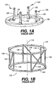
- a base such as a ring 120 (also known as a BRW head ring) in Fig. 1A.
- Ring 120 is firmly attached to the patient's skull via uprights 122 and sharp pins 124 throughout scanning and surgery.
- Structure 100 comprises an upper circular ring 102 in parallel with a lower circular ring 104.
- Lower ring 104 is mounted to reference ring 120 so that the three rings 102, 104 and 120 are in parallel planes.
- Rings 102 and 104 are interconnected by six vertical rods 106 and three diagonal rods 108. These specific marking rods are also called fudicels.
- the three diagonal rods 108 diagonally interconnect rings 102 and 104. Any plane orthogonal to an axis 110 of structure 100 which passes through structure 100 will create a unique pattern of six cross sectional views of rods 106 and three cross sectional views of rods 108.
- Fig. 1C shows, for example, the spacing of the rods when the position of the scan plane 112 is parallel to and midway between rings 102 and 104 of structure 100.
- the images obtained are analyzed and the position of rods 106 and 108 shown in the images is measured.
- the specific location of a scan with respect to structure 100 and therefore with respect to base ring 120 can be determined.
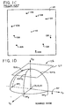
- the scans can be arranged within a scanned image coordinate system 125 with the reference plane RP set in fixed relation to the position of ring 120.
- a scan plane SP can be defined within the scanned image coordinate system 125 by at least three reference points SP1, SP2 and SP3 located on the head of the patient.
- the surgeon can use the stereotactic system to calculate a specific position within the brain corresponding to a scan image and then target that portion of the brain with a probe.
- the structure 100 used during scanning is removed from ring 120 and a specially designed caliper frame 200, as illustrated in Fig. 2A, is attached to ring 120.
- Frame 200 holds a surgical probe 202 which is positioned on an arch 206 for insertion into the patient's head.
- Frame 200 indicates the alpha, beta, gamma and delta angles on scales 208, 210, 212 and 214 for directing probe 202 to a particular target, as shown in Fig. 2B.
- the distance 216 from the tip of probe 202 to arch 206 is also determined.
- a computer is then used to correlate the position of the targeted scan image in the scanned image coordinate system with the corresponding angles alpha, beta, gamma and delta and distance 216 on frame 200 to enable the surgeon to apply the probe to the targeted area of the brain.
- a target picked out on a scan of a specific image can be approached with a fair degree of accuracy using this surgical procedure.
- the surgeon has also used the stereotactic system in reverse in order to determine the position of the probe 202 in the brain relative to the scanned images so that the scan image corresponding to the probe position can be identified and viewed.
- the surgeon again attaches frame 200 to ring 120.
- Probe 202 is then positioned in frame 200 and inserted into the brain.
- Frame 200 is then removed from ring 120 and mounted to a phantom base 250 in a manner as illustrated in Fig. 2A.
- Phantom base 250 has a coordinate system (X 1 , Y 1 , Z 1 ).
- caliper frame 200 identifies a point 201 over phantom base 250.
- a pointing device 252 is positioned to have its tip 254 at point 201.
- the X 1 - Y 1 plane of phantom base 250 is parallel to the plane in which the reference points RP1, RP2 and RP3 are located.
- the (X 1 , Y 1 , Z 1 ) coordinates define the position of point 201.
- the position of point 254 with respect to the X 1 - Y 1 plane and, therefore, with respect to the reference plane RP is now known.
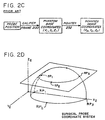
- a computer is used to calculate the specific position within the brain and the particular scan which corresponds to the calculated position can now be accessed and viewed on a scanning system. This prior art process is shown in diagram form in Fig. 2C.
- stereotactic surgery as performed with the apparatus of the prior art allows a surgeon to be guided to a specific point with accuracy, it has not been particularly useful in allowing the surgeon to identify the particular location of a probe within the brain at any point during the surgical process. Frequently in neurosurgery, brain tumors or other target points within the brain are indistinguishable from surrounding normal tissue and may not be detected even with the use of frozen sections. Moreover, with modern microsurgical techniques, it is essential that the neurosurgeon identify specific structures within the brain which are of critical functional importance to the patient. The boundaries of these structures must be accurately defined and specifically known to the surgeon during the surgical process. In this way, these tissues will not be disturbed or otherwise damaged during the surgical process which would otherwise result in injury to the patient. The minimal accuracy afforded by stereotactic surgery is generally insufficient for modern microsurgical techniques. Consequently, stereotactic surgery is not generally available to the majority of patients undergoing surgery.
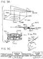
- Figs. 3A - 3C and 5 illustrate a system which includes sound emitters 360 and 370 and microphone detectors 350 and associated hardware to determine the position of probe tip 301 relative to a reference ring 306 on the patient's head. Because the position of the scanned images relative to reference ring 306 is known from the scanning procedure, the position of probe tip 301 relative to the scanned images is known and the relevant image can be displayed. Figs.
- FIG. 3A and 4A - 7 illustrate a system which includes infrared emitters 540 and 545 and detectors 550 in place of the sound emitters 360, 370 and microphone detector 350 for determining the position of a reference bar 548 and a probe tip 541.
- a computer 396 and an infrared scanner 380 relate the scanned images to the shape of the forehead and relate the shape of the forehead to the position of reference bar 548.
- Reference bar 548 is then associated with the scanned images through the forehead shape without the use of the cylindrical reference frame 100 during scanning.
- the use of the forehead shape as a reference point also allows the scanned images from different scanning technologies to be interrelated.
- 3D uses reference pins 307 affixed to the skull for determining the position of the patient's head during surgery.
- Figs. 9-11 use a removable cap for holding markers during scanning. The positions of the markers are marked on the head for later use during surgery in registering the surgical space with the scan images.
- Fig. 6 includes an ultrasound probe 500 for use during surgery. Other advantages are also provided as more fully described below.
- probe tip 301 In relating the position of a probe tip e.g. , probe tip 301, to a scanned image, it can be seen in Figs. 1D and 2D that the surgeon must know the specific location of tip 301 with respect to the scanned image coordinate system (X 0 , Y 0 , Z 0 ) of the scans that were preoperatively performed.
- probe tip 301 has a particular coordinate system (X 2 , Y 2 , Z 2 ) which is illustrated in Fig. 2D.
- the surgical probe coordinate system (X 2 , Y 2 , Z 2 ) must be related to the scanned image coordinate system (X 0 , Y 0 , Z 0 ).
- the invention uses a 3D digitizer system to locate the position of probe tip 301 within the probe coordinate system (X 2 , Y 2 , Z 2 ) and to relate it to the scanned image coordinate system (X 0 , Y 0 , Z 0 ).
- Figs. 3A and 3B show a microphone array 300, a temperature compensation emitter 304, a surgical probe 302, and a base ring 306.
- Microphone array 300 includes a plurality of microphones 350 which are preferably spaced one meter apart. Microphones 350 may be attached to the operating light above the patient's head in direct line of sight of all of the emitters 360 and 370. Microphones 350 thereby detect the sound emitted from the emitters.
- Surgical probe 302 preferably is a surgical coagulating forceps such as a bipolar coagulating forceps. Probe 302 could also be a drill, suction tube, bayonet cauterizing device, or any other surgical instrument modified to carry at least two sound emitters 360 thereon for determining position.
- Emitters 360 on probe 302 are essentially coaxial on an axis 362 with tip 301. Emitters 360 are in line and immediately below the surgeon's line of sight so that the line of sight is not blocked. Probe 302 has a bundle of wire 364 attached thereto for connection to an electrical power source. The wires required to energize emitters 360 are combined with bundle 364. The surgeon is familiar with handling such a probe connected to a wire bundle; therefore, this apparatus does not inconvenience the surgeon.
- ring 306 is affixed to the reference ring 120 attached to the patient's head and is essentially coplanar with it. Ring 306 includes a plurality of emitters 370 which are preferably positioned 90 degrees apart with the center emitter being located at the anterior of the head. This permits ring 306 to be mounted around the head so that all three emitters are in line of sight with array 300.
- each of emitters 360 and 370 is determined individually in order to determine the position of the devices to which the emitters are attached. This is accomplished by rapidly energizing the emitters one at a time in a predetermined sequence and measuring the time required for the individual sounds to reach each of microphones 350 in array 300.
- a 3D digitizer 312 controls this operation through a signal generator 308 and a multiplexer 310. Digitizer 312 may be an off-the-shelf Model GP-8-3D three dimensional sonic digitizer produced by Scientific Accessories Corporation.
- multiplexer 310 applies an energizing signal from signal generator 308 first to a temperature compensation emitter 304, then sequentially to emitters 370 on ring 306, then sequentially to emitters 360 on probe 302.
- digitizer 312 receives and digitizes the output signals produced by microphones 350 in response to the energizations of the emitters.
- the digitized output signals are output to a computer 314.
- Computer 314 is programmed with the predetermined pattern and timing for energizing emitters 360 and 370.
- Computer 314 includes a spatial acquisition and recording (SAR) program 316 which acquires and records spatial coordinates based on the digitized signals.
- the SAR program 316 may be the SACDAC program licensed by PIXSYS of Boulder, Colorado.
- SAR program 316 measures the time of transmission from each of the emitters to each of the microphones 350. By comparing these times, SAR program 316 calculates the position of each of emitters 360 and 370. Since ring 306 contains three emitters 370, SAR program 316 can calculate the position of ring 306 through standard geometric computations.
- This plane essentially defines the reference plane of the scan images because it is coplanar with the reference points RP1, RP2 and RP3 in the scanning coordinate system of Fig. 1D.
- SAR program 316 can calculate the position of probe tip 301 through standard geometric computations. After SAR program 316 determines the respective positions of ring 306 and probe tip 301 relative to array 300, it next determines the position of ring 306 relative to tip 301 within the probe coordinate system of Fig. 2D.
- temperature compensation emitter 304 is located in a fixed position relative to array 300.
- Temperature compensation emitter 304 may be, for example, a sonic digitizer as is used in the Scientific Accessories Corporation Model GP-8-3D. SAR program 316 knows, through calibration, the distance between temperature compensation emitter 304 and each of the microphones 350 of array 300.
- SAR program 316 can immediately calculate the reference standard, i.e., the velocity of the emitted sound through the air. This instantaneous reference is applied to the sound emitted from the other emitters 360 and 370 to determine accurately the position of the other emitters.
- SAR program 316 After SAR program 316 has accurately determined the position of probe tip 301 in the probe coordinate system shown in Fig. 2D, it outputs the coordinates to translational software 318 in computer 314. Translational software 318 then translates the coordinates from the surgical probe coordinate system of Fig. 2D into the scanned image coordinate system shown in Fig. 1D, as more fully described below.
- a memory 320 accessed through a local area network (LAN) 321 stores each of the images of the preoperative scan according to the respective positions of the scans within the scanned image coordinate system of Fig. 1D. The respective positions of the scans are known from the position of rods 106 and 108 in the scans, which information is stored in memory 320.
- LAN local area network
- Stereotactic image display software 322 actuates a stereotactic imaging system 324 to generate a scan image from the data stored in memory 320 corresponding to the translated coordinates.
- Stereotactic imaging system 324 displays the generated image on a high resolution display 326.
- Display 326 preferably displays the axial, saginal and coronal views corresponding to probe tip 301.
- Stereotactic image display software 322 and stereotactic image system 324 may be any off-the-shelf system such as manufactured by Stereotactic Image Systems, Inc. of Salt Lake City, Utah.
- This cycle of calibrating the system through temperature compensation emitter 304, sequentially energizing emitters 370 and 360 to determine the respective positions of ring 306 and probe 302, and generating and displaying a scan image corresponding to the position of probe tip 301 all occur each time the surgeon closes a switch to activate the system.
- the switch (not shown) may be positioned on probe 302, in a floor pedal (not shown), or wherever else may be convenient to the surgeon.
- ring 306 is one apparatus for determining and positioning the reference points RP1, RP2 and RP3 with respect to microphone array 300.
- An advantage of ring 306 is that, each time emitters 360 on probe 302 are energized, emitters 370 on ring 306 are also energized to redefine the reference plane. This allows the surgeon to move the patient's head during surgery.
- the reference points RP1, RP2 and RP3 can be established with the 3D digitizer 312 and three reference pins 307.
- Reference pins 307 are radiolucent surgical screws with radiopaque tips. Pins 307 are permanently affixed to the patient's skull before surgery and before the preoperative scanning. The radiopaque tips thereby provide a constant reference during scanning and throughout the stereotactic surgical procedure.
- probe tip 301 is positioned on each of pins 307 and actuated to emit a signal which is detected by microphone array 300 and output to 3D digitizer 312. This allows the position of tip 301 to be determined at each of these points. This is performed during a reference mode of operation of 3D digitizer 312.
- SAR program 316 calculates the position of the reference points RP1, RP2 and RP3.
- the use of pins 307 requires that the reference points have to be reestablished before the position of probe 302 is determined to avoid changes in the reference plane due to movement of the head.
- emitters 370 may each be separately mounted to pins 307 or other fixed structures positioned at each of the reference points.
- this process is illustrated in Fig. 3C and identifies the location of probe tip 301 for the surgeon.
- the reference plane is determined by energizing ring 306 or by positioning probe tip 301 at the reference points.
- the emitters of probe 302 are energized so that the position of probe tip 301 in the head is determined in the probe coordinate system (X 2 ,Y 2 ,Z 2 ).
- Translational software 318 then converts the probe coordinate system into the scanned image coordinate system (X 0 ,Y 0 ,Z 0 ) so that the image corresponding to the position of probe tip 301 can be generated and displayed.
- infrared emitters 540 and 545 and an array 552 of detectors 550 are used respectively in place of sound emitters 360 and 370 and microphones 350 of Fig. 3B.
- Fixed reference bar 548, a surgical probe 542, and related components are used in place of ring 306, probe 302, and related components of Fig. 3B.
- a Mayfield clamp 570 of known construction is used in place of ring 120 for rigid attachment to the patient's head 394.
- Clamp 570 includes sharp pins 572 attached to adjustable jaws 574 and 576. Clamp 570 is thereby adjusted for rigid attachment to head 394.
- Reference bar 548 is rigidly attached to clamp 570 so that there is no relative movement between bar 548 and head 394.
- No temperature compensating emitter such as emitter 304 in Fig. 3B is required in Fig. 4A because the apparatus of Fig. 4A uses the position of emitters 540 and 545 as viewed by detectors 550 (as more fully explained below) to determine probe and ring positions instead of the time of transmission of the emitted signal as with the embodiment of Fig. 3B.
- infrared detectors 550 are attached to a mounting bar 551 in fixed relation to each other.
- Detectors 550 are generally positioned so that their views converge on a phantom point.
- the two outer detectors 550L and 550R may view a field of two intersecting vertical planes and the center detector 550C would view a horizontal plane. This can be accomplished by employing vertical slits on the field of view of the outer detectors and a horizontal slit on the field of view of the center detector.
- the phantom point is set to be in the general vicinity of the patient's forehead 390.
- Mounting bar 551 is suspended from the operating room light in direct line of sight of the patient's forehead 390 and of emitters 540 and 545.
- Detectors 550 thereby detect the infrared light emitted from emitters 540 and 545.
- Detectors 550 include a large number of linear chip cameras such as CCD (charge coupled device) cameras or pixels.
- a cylindrical lens (not shown) may also be used behind the slits in detectors 550 to collimate the infrared light.
- Figs. 4A, 4B, 6A, 7 and 8 may be controlled with the computer and other hardware shown in Fig. 3A using the software shown in Fig. 5. Apart from the use of infrared light in place of sound and the measurement of the position of the emitters through geometry instead of the timed delay of sound, the operation of this hardware and software parallels the operation disclosed above.
- infrared light allows for the use of the contour of a portion of the patient's head 394, preferably the forehead 390 above and around the patient's eyes, to relate the position of the probe 542 to the scan images.
- This is accomplished with an optical scanner 380 which generates an infrared laser beam which is reflected off of the patient's forehead 390 in timed sequence with the firing of emitters 545 to determine the forehead contour relative to reference bar 548.
- Such optical scanning of the forehead allows preoperative scanning to occur well in advance of anticipated surgery and without intubation.
- Figs. 4A and 4B include infrared detector array 552, probe 542, reference bar 548 and optical scanner 380.
- Surgical probe 542 preferably is a surgical coagulating forceps such as a bipolar coagulating forceps.
- Probe 542 could also be a drill, suction tube, bayonet cauterizing device, or any other surgical instrument modified to carry at least two infrared emitters 540 thereon for determining position.
- Emitters 540 on probe 542 are essentially coaxial on an axis 544 with tip 541. Emitters 540 are in line and immediately below the surgeon's line of sight so that the line of sight is not blocked.
- Probe 542 has a bundle of wire 364 attached thereto for connection to an electrical power source.
- Bar 548 comprises a bar with a plurality of at least three infrared emitters 545 positioned thereon.
- the line of sight between some of the emitters 545 and the array 552 may be blocked by a surgical hose or other object. This could temporarily prevent array 552 from detecting the position of bar 548.
- Such additional emitters can also be used to more precisely locate the position of bar 548.
- Optical scanner 380 is generally located in front of the patient's forehead 390.
- Optical scanner 380 and its associated software to generate a forehead image are standard, off-the-shelf components such as those used to scan an object to determine its three-dimensional shape.
- a limb scanner such as the PIXSYS Optical Scanner used to develop three-dimensional models for artificial limbs may be used.
- head 394 is fastened securely in a cushioned cradle 392 with surgical straps (not shown). If the contour of forehead 390 appears in the scan images, then computer 396 employs forehead fitting software 398 to derive the forehead contour from the scan images and to database the scan images as a function of the forehead contour in memory 320. If the scan images do not show the forehead 390, then (as shown in Fig. 7) head 394 is firmly clamped in fixed relation with a reference source, such as a ring 590, having emitters 592 thereon.
- a reference source such as a ring 590, having emitters 592 thereon.
- Optical scanner 380 is then used to determine the position of the forehead contour relative to ring 590 (as more fully described below). Because the position of the scan images relative to ring 590 is known from the scanning procedure, the position of the scan images relative to the forehead contour is known. This information is then databased in memory 320 and used during surgery to relate the position of probe 542 to the scan images.
- Forehead scanning with optical scanner 380 is accomplished in the following way.
- head 394 is rigidly attached to ring 590 in Fig. 7. This attachment may be accomplished with a base ring (not shown) such as ring 120 in Fig. 3B.
- scanner 380 emits an infrared laser beam which bounces off a single point on forehead 390 and is detected by array 552.
- Computer 396 determines the position in space of this first point on forehead 390, such as by triangulation.
- emitters 592 on ring 590 are energized sequentially.
- Array 552 detects these emissions and computer 396 determines the relation between the first detected position on forehead 390 and the position of ring 590.
- head 394 Prior to surgery, head 394 is clamped with a mechanism such as the Mayfield clamp 570 shown in Fig. 4A for maintaining head 394 in rigid position.
- Reference bar 548 is rigidly attached to clamp 570 with emitters 545 in line of sight with array 552.
- Optical scanner 380 next scans the forehead to determine the position of the forehead contour relative to bar 548.
- the forehead contour derived from this second optical scanning is matched to the forehead contour stored for the scanned images in memory 320 so that the current position of bar 548 with respect to the scanned images is known.
- the forehead contour matching between the stored forehead contour and the forehead contour derived from the second optical scanning is accomplished using the well known Pellazari Chen algorithm or any other suitable surface matching algorithm.
- Bar 548 used during surgery includes emitters 545 which communicate with array 552 to establish the position of bar 548. Since the position of probe 542 relative to bar 548 is known (because of communication via emitters 540 and 545 and array 552) and since the position of bar 548 relative to the scanned images is known, the position of probe 542 relative to the scanned images is known. Accordingly, a scanned image corresponding to the position of tip 541 of probe 542 is generated and displayed.
- One advantage of using either optical scanner 380 or surgical pins 307 in establishing a reference is that the reference ring, such as ring 120, is removed after preoperative scanning and before surgery. This is advantageous because the patient can not be intubated while ring 120 is attached to the skull. In the prior art, where ring 120 can not be removed during the time between preoperative scanning and surgery, the patient must be intubated (and therefore anesthetized) prior to preoperative scanning. Thus, by using the contour of forehead 390 to define the reference point, the preoperative scanning is performed without the need for intubation and the anesthesia accompanying it. This is particularly advantageous during PET, MEG and any other type of functional scanning where the patient must be conscious to elicit behavior during scanning. It is also advantageous during any form of scanning where the medical equipment for providing intubation and anesthetic would otherwise interfere with the scanning technology, such as MRI scanning.
- the patient when CT scanning is used, the patient lies with the head held in place on a CT table during the preoperative scanning process.
- the scans are organized in memory 320 according to the forehead contour appearing in the scans.
- the patient's head 394 Prior to surgery, the patient's head 394 is rigidly held in a Mayfield clamp or similar clamp on which reference bar 548 is mounted.
- Optical scanner 380 is then used to determine the patient's forehead contour relative to bar 548. Since the position of the scan images relative to the forehead contour is already known, the position of bar 548 relative to the scan images is known. During surgery, the surgeon positions probe 542 in the position desired within head 394.
- Emitters 540 of probe 542 and emitters 545 of bar 548 are then energized so that the position of probe tip 541 relative to bar 548 and, therefore, relative to the scan images is known. This is accomplished through the translational software 318 which converts the probe coordinate system (X 2 , Y 2 , Z 2 ) into the scanned image coordinate system (X 0 , Y 0 , Z 0 ) so that the image corresponding to the position of probe tip 541 can be generated and displayed.
- MRI, PET or MEG scanning when MRI, PET or MEG scanning is used, the patient lies on an MRI, PET or MEG table with head 394 rigidly attached to ring 590.
- Optical scanner 380 then scans forehead 390 to determine the position of the forehead contour relative to ring 590.
- the MRI, PET or MEG scanning is then performed and the scan images are produced in known relation to the position of ring 590 and, therefore, in known relation to the forehead contour.
- the scans are organized in memory 320 according to the forehead contour.
- head 394 Prior to surgery, head 394 is rigidly held in a Mayfield clamp or similar clamp on which reference bar 548 is mounted.
- Optical scanner 380 is then used to determine the patient's forehead contour relative to bar 548.
- the position of bar 548 relative to the scan images is known.
- the surgeon positions probe 542 in the position desired within head 394.
- Emitters 540 of probe 542 and emitters 545 of bar 548 are then energized so that the position of probe tip 541 relative to bar 548 and, therefore, relative to the scan images is known.
- This is accomplished through translational software 318 which converts the probe coordinate system (X 2 , Y 2 , Z 2 ) into the scanned image coordinate system (X 0 , Y 0 , Z 0 ) so that the image corresponding to the position of probe tip 541 can be generated and displayed.
- a flow chart of the operation of translational software 318 is shown as it is used with the apparatus of Fig. 3B.
- the surgeon locates probe 542 in the position which is to be determined.
- the initial step is for the surgeon to use the reference mode of 3D digitizer 312 to identify the reference plane by locating probe tip 541 at several points in the plane.
- the system then initializes at a step 400 so that translational software 318 opens a window menu at a step 402 of a multitasking program such as DESQ VIEW distributed by Quarterdeck Office Systems of Santa Monica, California.
- DESQ VIEW distributed by Quarterdeck Office Systems of Santa Monica, California.
- Such software permits simultaneous execution of multiple software programs. In general, once a program is selected for actuation, it continues to run either in the foreground or in the background until deactuated.
- Translational software 318 continues initializing by selecting stereotactic imaging system 324 through stereotactic image display software 322 and actuating stereotactic imaging system 324 in the foreground by opening the stereotactic window at a step 404. Thereafter, translational software 318 returns to the window menu at a step 406 moving stereotactic image display software 322 to the background and selects the digitizer window at a step 408 to actuate digitizer 312 in the foreground. Computer 314 is then ready to be actuated by the foot switch.
- a foot pedal or other switch which indicates that the system should perform a computation.
- Actuation of the foot switch is essentially the beginning of a start step 410.
- digitizer 312 initiates calibration through temperature compensation emitter 304 to determine the velocity of the sound waves in the air, energizes emitters 370 of ring 306 to locate the reference plane and energizes emitters 360 of probe 302 to locate the position of probe tip 301.
- the signals detected by microphone array 300 are digitized so that SAR program 316 determines the coordinates of tip 301.
- translational software 318 selects the coordinates from SAR program 316.
- the window menu is again accessed at a step 414 and the window menu switches stereotactic image system software 322 to the foreground at a step 416 to specifically control the operation of stereotactic imaging system 324.
- translational software 318 issues an F1 command to stereotactic image display software 322 which in turn prepares stereotactic imaging system 324 to accept coordinates.
- the window menu is again selected so that at a step 422 computer 314 switches the digitizer window into the foreground.
- the digitizer window menu is accessed and coordinate translation is selected.
- digitizer 312 begins calculating the coordinates and at a step 428 the coordinate calculation is ended.
- Translational software 318 then returns to the digitizer window menu at a step 430, switches windows to place stereotactic image system software 322 in the foreground at a step 432 to prepare it for receiving the coordinates and again returns to the main window menu at a step 434.
- the coordinate information is translated, including any necessary manipulation, and transferred to stereotactic image display software 322 at a step 436 which actuates stereotactic imaging system 324 to generate the particular image from memory 320 and display it on the high resolution display 326.
- Stereotactic image display software 322 instructs stereotactic imaging system 324 to display a cursor on display 326 at the coordinates which corresponds to the position of probe tip 301.
- computer 314 is in a standby mode until the foot switch of the surgeon is again actuated to execute translational software 318 beginning with the start step 410.
- the translation that occurs in step 436 depends on the position of the probe coordinate system relative to the scanned image coordinate system and the units of measure.
- the systems are preferably coaxial and the units of measure the same so that algebraic adjustment is unnecessary.
- the coordinates systems may not be coaxial, in which case translation would require arithmetic and/or trigonometric calculations.
- the sequence, e.g., (X 2 , Y 2 , Z 2 ), in which the coordinates are generated by the digitizer 312 may be different than the sequence, e.g., (X 0 , Y 0 , Z 0 ), in which the stereotactic image system software 322 receives coordinates. Therefore, the sequence in which the coordinates are transferred may have to be reordered.
- a personal computer could be directly programmed to calculate the coordinates of the position of probe tip 301 for use in generating the scan image corresponding to the position of tip 301 from the data stored in memory 320.
- the steps performed by translational software 318 for the system of Fig. 4A are similar to those described above for the system of Fig. 3B with the following exceptions.
- the system of Fig. 4A does not require a calibration emitter such as emitter 304 in Fig. 3B so that the corresponding step is skipped in the software for Fig. 4A.
- infrared emitters 540 and 545 are used in place of sound emitters 360 and 370 for determining the position of probe tip 541 and bar 548.
- the various positions of the emitters are determined based on the angle of the view of detectors 550 to each of emitters 540 and 545. The angle is known from knowing which pixel within each of detectors 550 detects the infrared light.
- translational software 318 for the system of Fig. 4A includes additional steps for operating optical scanner 380 through multiplexer 310 to scan a series of infrared laser beams across forehead 390 for detection by detectors 550. This data is received by digitizer 312 and passed to computer 396 so that the forehead contour can be determined through software 398. Data identifying the forehead contour is then passed back to translational software 318 for use as a reference.
- the ultrasound system includes a mechanism such as a Mayfield head clamp 570 for maintaining head 394 in rigid position.
- Reference bar 548 is rigidly attached to clamp 570 as above with emitters 540 in line of sight with array 552.
- the forehead contour is determined by optical scanning using optical scanner 380 and array 552 of detectors 550 as shown in Fig. 4A and as more fully described above.
- the ultrasound system also includes an ultrasound probe 500 which may be used in the operating room to scan the brain.
- Ultrasound probe 500 includes a plurality of at least three noncolinear emitters 502 which are energized via a line 504 by multiplexer 310.
- the signal emitted by emitters 502 is received by array 552 to determine the position of the body of ultrasound probe 500 relative to the position of forehead 390. This is accomplished through translational software 318 which controls digitizer 312 and multiplexer 310 to energize emitters 502 in a predetermined sequence to determine the position of the body of probe 500. This is the same technique used above in Figs. 3B and 4A for determining the position of probes 302 and 542 and of rings 306 and 548.
- Ultrasound probe 500 is also connected via a line 506 to a system 508 of known construction which analyzes the ultrasound scanning and provides the analyzed information to a monitor 510 which displays the ultrasound image. Since array 552 can determine the position of the body of ultrasound probe 500 at any point in time, via digitizer 312, the particular plane of the image displayed on monitor 510 is known.
- FIG. 6B An ultrasound image is illustrated by way of example in Fig. 6B. Because the plane of the ultrasound scan image is known, the surgeon can signal stereotactic imaging system 324 to generate a scan image from a different scanning technology on display 326 which corresponds to the ultrasound image. Fig. 6C illustrates such a corresponding image.
- system 508 may be linked to stereotactic imaging system 324 directly via a data link 515 to communicate the position of the scan plane for the image shown on monitor 510 so that stereotactic imaging system 324 can automatically generate and display the corresponding scanned image for a different scanning technology on display 326.
- the image from the ultrasound system is shown on one monitor and may be compared to a corresponding image obtained from CT, MRI, PET, MEG or some other type of preoperative scanning.
- the cross section through the three dimensional data set as developed by the ultrasound system is determined by a high speed graphics system 508, such as manufactured by Silicon Graphics.
- This allows for better interpretation of the ultrasound scans as the anatomy from the MRI, CT, PET or MEG scans can be seen directly.
- the ultrasound system allows scanning in the operating room. Since the brain tissue is elastic and the position of various tissue may change from time to time, use of an ultrasound scan in the operating room permits a more definite localization of various brain tissues.
- ultrasound probe 500 is shown in Fig. 6A as spaced away from head 394. Usually, ultrasound probe 500 is positioned in contact with the skull during use. The probe may also be affixed to the skull during surgery for continual monitoring of the position of the brain.
- Fig. 7 shows a system for correlating the scan images from different scanning technologies.
- a scanner 600 represents any of the several scanning technologies currently available (e.g. CT, MRI, PET, MEG) and is intended to include any other scanning technologies that may be developed.
- Scanner 600 scans head 394 in a plane 602. Plane 602 is usually defined visually by an array of light beams. If the pertinent scanning technology reveals the position of the forehead contour in the scan images, then computer 396 employs forehead fitting software 398 to derive the forehead contour from the scan images. Computer 396 organizes the scan images as a function of the forehead contour for storage in memory 320.
- ring 590 is rigidly attached to head 394.
- the optical scanner 380 is used prior to scanning to relate the position of the forehead contour relative to ring 590 (as described in the text accompanying Fig. 4A).
- Ring 590 lies in a plane 604.
- planes 602 and 604 are preferably maintained in parallel relation by initially aligning ring 590 coplanar with the visual array of light beams defining plane 602.
- the orientation of the forehead relative to the scan plane can be calculated.
- ring 590 will appear in at least one scan and since the position of one scan within a group is known with respect to the other scans in the group, the respective positions of the scans relative to ring 590 is known. Since the position of the forehead contour relative to ring 590 was determined by scanning the forehead with scanner 380, the position of the forehead contour relative to the scan images is known.
- Computer 396 now employs forehead fitting software 398 to organize the scan images as a function of the forehead contour. This information is databased in memory 320. The forehead contour is then used to relate the scan images of one technology such as PET to the scan images produced from any other technology such as CT, MRI, or MEG.
- Fig. 8 shows a laser depth finder 620 for use in scanning the forehead contour when the line of sight between optical scanner 380 and array 552 in Fig. 4A is blocked.
- Fig. 8 includes a Mayfield clamp 570 for holding head 394 in fixed relation to a reference bar 548 having emitters 545 thereon.
- Depth finder 620 may be any of the laser based depth finders commonly available which are accurate to within the required tolerances.
- At least three emitters 622 are affixed to depth finder 620. Emitters 622 are controlled via multiplexer 310 so that computer 314 can determine the position of depth finder 620 in addition to the position of bar 548.
- depth finder 620 emits an infrared laser beam which is reflected off forehead 390 and detected by a detector within depth finder 620.
- the circuitry inside depth finder 620 calculates the distance between the illuminated point on forehead 390 and a reference point on depth finder 620 and outputs a signal corresponding to the calculated distance via a line 624 to computer 314.
- Computer 314 then sequentially fires emitters 545 and 622 via multiplexer 310 to determine the positions of bar 548 and depth finder 620. Accordingly, at the end of this first cycle, one point of the forehead contour can be calculated. This cycle is repeated a number of times until computer 314 has obtained sufficient points to map the forehead contour.
- Figs. 9-11 show an alternative system for registering scan images with the surgical space.
- Fig. 9 includes a cap 700 which fits snugly over head 394. Cap 700 is secured by an adjustable strap 702. In use, there should be no relative movement between cap 700 and head 394.
- a plurality of grommets 704 are sewn into cap 700 at regular intervals.
- Fig. 10 shows one such grommet in greater detail and
- Fig. 11 shows the cross-section through Fig. 10 at the indicated line. As can be seen in these figures, grommets 704 encircle and thereby reinforce fabric 706 of cap 700.
- a hole 707 centrally positioned within each grommet 704 is cut into fabric 706 and provides space for supporting a marker 708 and also provides access to underlying skin 710 on head 394.
- Fabric 706 is preferably elastic in nature.
- the hole 707 in fabric 706 is smaller than the external dimensions of marker 708 so that fabric 706 is stretched slightly to hold marker 708.
- hole 707 may be a slit within fabric 706.
- Markers 708 include an internal reservoir filled with a radiopaque substance which is detected by the scanner during scanning and which appears on the scan images.
- the markers for CT scanning are filled with omnipaque
- the markers for MRI scanning are filled with gadolinium
- the markers for PET scanning are filled with a radioactive tracer.
- the capacity of the reservoirs in markers 708 is different for the different scanning technologies because each scanning technology has a different resolution.
- markers 708 preferably have a uniform external dimension so that the same cap 700 can be used with any of the different types of scanners and related markers. Markers 708 are easily attached within and removed from fabric 706 to allow quick access for marking skin 710 underneath. This is also helpful for patients who are undergoing more than one scanning procedure using different scanning technologies.
- markers for the different technologies may be attached to fabric 706 within the same grommets 704 so that the images produced by the different scanners all show markers 708 in the same places.
- Markers 708 preferably consist of clear plastic material such as polyethylene tubing filled with a contrast medium in the center and sealed at both ends with epoxy 712. Markers 708 can be either prefilled and sealed with suitable contrast medium or fillable by needle puncture with the contrast medium.
- cap 700 is preferably made of fabric consisting of 85% Dupont Antron NylonTM and 15% Lycra SpandexTM. Although one size may fit most patients, the cap 700 can be sized or shaped to specific patients. Three-quarter inch 19.05 mm grommets 704 are sewn at routine intervals over the entirety of the cap. For surgery on other parts of the body, a flexible material is used which fits snugly like an ace wrap bandage. Again, grommets 704 are sewn every one or two inches every 2.54 or 5.08 cm. As with cap 700, there is a hole in the fabric 706 in the center of each grommet for holding markers 708.
- the patient is instructed to wash his/her hair and to not apply any hair spray, lotion, or other materials prior to scanning in order to provide as oil-free of a surface as is possible.
- cap 700 is snugly fit over head 394 and secured with chin strap 702, the surgeon selects at least three (preferably more) grommets 704 which will be used to hold markers 708.
- markers 708 are preferably placed over the largest area available to insure a low margin of error. If surgery is planned, hair surrounding the operative area can be clipped or left in place as desired by the surgeon. A small amount of hair is clipped or displaced around the area where markers 708 will be used to allow the positioning of markers 708 close to skin 710.
- Skin 710 is marked with indelible ink 716 through the holes in fabric 706 of the grommets 704 in which a marker 708 is to be attached. Markers 708 are then attached to said fabric. During this time, the surgeon carefully checks to insure that each marker 708 is positioned adjacent to and directly over the ink mark 716 on skin 710. Ink mark 716 is preferably positioned in the center of the hole in fabric 706. The patient is then positioned on the scanning table and head 394 is scanned. After scanning, markers 708 are removed. During removal of the markers, the surgeon carefully checks to see that each marker did not move during scanning by checking to see that each is still positioned adjacent to and directly over the corresponding ink mark 716.
- the ink marks should appear in the center of the holes in fabric 706. If a marker is no longer in position adjacent the related ink mark and/or if the ink mark is not in the center of the hole, it indicates that movement of the marker has occurred some time during scanning. Accordingly, the particular ink mark 716 and its corresponding marker 708 are not used during the subsequent registration process where the scan images are registered with the surgical space. If enough of the markers have moved from their positions so that the position of three of the markers can not be confirmed, then the scan is repeated.
- the indelible ink marks 716 may need no protection from the possibility of smudging or accidental removal.
- the patient is issued a paper cap to wear until the time of surgery and is instructed not to remove or interfere with the ink marks. If there will be a delay between scanning and surgery, there are several ways to assure the integrity of the indelible marks. For example, benzoin can be applied to the area surrounding the indelible mark and allowed to dry. A strip of three-quarter inch 19.05 mm transparent tape is then applied to the area. Collodium may also be used in a similar way to protect the marks.
- a three point solution utilizing directional cosines from two frames of reference enables the surgeon to register the surgical space with the scan images. If the integrity of more than three marks 716 is confirmed, the additional marks can be used for redundancy to insure that the registration was properly performed.
- the registration process can be accomplished using the apparatus shown in Figs. 4A and 3A.
- computer 314 processes and stores the scan images in memory 320 as a function of the markers 708 which appear in the scan images using similar techniques as those described above. Prior to surgery, head 394 is clamped in clamp 394.
- the tip 541 of probe 542 is then touched on each of the ink marks 716 on skin 710 of head 394 while the emitters 540 and 545 are energized. Because computer 314 now knows the position of each of ink marks 716 relative to reference bar 548, it can determine the position of the scan images relative to reference bar 548. During surgery, as described above, emitters 540 and 545 enable computer 314 to also know the position of probe tip 541 relative to reference bar 548. Accordingly, computer 314 knows the position of probe tip 541 relative to the scan images. Computer 314 then generates a scan image corresponding to the position of tip 541. The generated image is displayed on display 326.
- cap 700 and markers 708 to register the scan images to the surgical space.
- the placement of markers 708 does not cause any pain to the patient. This is because markers 708 are noninvasive and do not require the skin to be broken when they are used. Accordingly, redundant markers are used which provide greater accuracy and which insure in most cases that at least three of the markers will be useable for registering the scan images.
- Another advantage is that routine scans can be taken with markers 708 in place. If the initial scan locates a lesion that required surgery, the position of the scan images relative to markers 708 is known and the same scan images can be used during surgery.
- markers 708 are removed prior to surgery and so they do not need to be sterilized. Thus, the difficulty otherwise encountered in trying to sterilize such markers is avoided.
- a material with grommets 704 sewn at regular intervals is wrapped once around the part being examined and attached with fasteners that do not distort the image produced.
- the material is applied snugly, like an ace wrap, with grommets every one to two inches every 2.54 cm to 5.08 cm.
- the fabric can be made into a corset like structure, with the salient feature being reinforcement with grommets that allow holes to be made in the fabric without weakening it, and that also allow placement of markers 708.
- the skin is marked with indelible ink 716 under each marker. After scanning, marker 708 is removed and the skin mark 716 is checked to insure that the marker has not moved.
- apparatus other than cap 700 could be used for positioning markers 708 within the scope of the invention.
- markers 708 can be held in place adjacent an ink mark 716 using tape.
- Such transparent tape has been found to be particularly effective in positioning markers on the forehead and other hairless areas.
- apparatus other than grommets 704 and fabric 706 can be used to hold markers 708 within cap 700.
- Such other apparatus includes any of the commonly found fasteners and mechanical fixtures capable of holding relatively small objects.
Description
- Precise localization of position has always been critical to neurosurgery. Knowledge of the anatomy of the brain and specific functions relegated to local areas of the brain are critical in planning any neurosurgical procedure. Recent diagnostic advances such as computerized tomographic (CT) scans, magnetic resonance imaging (MRI) scanning, positron emission tomographic (PET) scanning, and magnetoencephotographic (MEG) scanning have greatly facilitated preoperative diagnosis and surgical planning. However, the precision and accuracy of the scanning technologies have not become fully available to the neurosurgeon in the operating room. Relating specific structures and locations within the brain during surgery to preoperative scanning technologies has previously been cumbersome, if not impossible.
- Stereotactic surgery, first developed 100 years ago, consists of the use of a guiding device which channels the surgery through specific parts of the brain as localized by preoperative radiographic techniques. Stereotactic surgery was not widely used prior to the advent of modern scanning technologies as the injection of air into the brain was required to localize the ventricles, fluid containing chambers within the brain. Ventriculography carried a significant complication rate and accuracy in localization was marginal.
- In WO-A-91/07726 there is disclosed a computerized system for viewing of internal anatomical regions of a patient based on previously acquired image data of the patient. The anatomical regions are viewed in direct relationship to a moving probe which can be hand-held. The location of the probe relative to the patient is reported to the computer. The computer then uses the previously acquired image data to generate a desired view of the patient's anatomy in relationship to the position or orientation of the probe. An operator is able to visualize normally invisible anatomical features before commencing, and during, procedure. The correspondence between positions of the patient's anatomy to locations on the stored data images is determined through an initialization procedure which can be repeated or refined between viewing operations. The system may be employed during diagnostic, therapeutic, or surgical procedures.
- US-A-4791934 proposes generating diagnostic mapping data representing a series of planar slices through a patient by a CT or other multi-plane scanner. This data is stored in an image memory. To free the CT or other scanner for other patients, the mapping data and patient are transferred to a second location. At the second location, the patient is restrained in a digital radiographic imaging apparatus in which data representing a shadowgraphic image is generated and stored in a reference memory. The transferred mapping data is stored in a second image memory at the second site. A shadowgraphic image synthesizer is used to synthesize an analogous shadowgraphic image from the diagnostic mapping data in the second image memory taken relative to a selected spatial position and angular orientation. The reference and synthesized shadowgraphic images are then superimposed or otherwise concurrently displayed on a video display. The spatial position and angular orientation from which the synthesized image is projected are adjusted until an optimal match between the superimposed images is achieved. In this manner, the current actual position of the patient and the diagnostic data in the second image memory are brought into registration. From images representing slices through the patient reconstructed from data in the image memory, the physician can plan a point of entry and path through the patient which a surgical instrument is to follow. A surgical instrument guide is positioned such that the surgical instrument enters the patient at the coordinates at the selected point of entry and follows the selected path.
- WO-A-92/06645 discloses a system for determining a position of a probe relative to an object such as a head of a body of a patient. The head includes a surface such as a forehead having a contour. The head is placed in a cradle equipped with an arc. The cross-sectional images of the head are determined relative to the arc. A hand-held unit optically scans the forehead and the arc. During scanning to generate the cross-sectional images, the optical scanner is used to determine the position of the forehead relative to the cradle. During surgery, the optical scanner also determines the position of the forehead relative to a base ring. An array for receiving radiation emitted from the probe and from the base ring generates signals indicating the position of the tip of the probe relative to the base ring. A stereotactic imaging system selects and displays the image of the head closest to the measured position of the tip of the probe.
- It is an object of this invention to provide a system which can determine the position of a probe within an object and display an image corresponding to the determined position. It is a further object of this invention to provide a system which can determine the position of an ultrasound probe relative to an object and, still further, which can display scan images from other scanning technologies corresponding to the scan images produced by the ultrasound probe. It is a further object of this invention to provide a system which can relate scan images of an object produced with one technology to scan images of the same object produced with another technology.
- The invention comprises a system for indicating a location within a body of a patient. The system includes a laser depth finder for determining the position of a reference contour, such as a contour of the patient's forehead, having a position in fixed relation to the body. It also includes means for generating images of the body, the images including reference images corresponding to the reference contour. In addition the system includes reference means having a location outside the body for providing a reference, and a surgical probe including a tip having a position. A first means is provided for determining the position of the tip of the surgical probe relative to the reference means. The system additionally includes second means for determining the position of the laser depth finder relative to the reference means and the position of the reference contour of the body relative to the reference means so that the position of the tip relative to the reference contour of the body is a known position. It also includes means for translating the known position of the surgical probe to provide a translated position within a coordinate system corresponding to the images of the body, and also means for displaying an image of the body to provide a displayed image that corresponds to the translated position of the tip of the surgical probe.
- Other objects and features will be in part apparent and in part pointed out hereinafter.
-
- Fig. 1A is a perspective illustration of a reference
ring of the prior art which is mounted by uprights to a
patient's head to support the cylindrical frame structure
of Fig. 1B or the
ring 306 of Fig. 3B. - Fig. 1B is a perspective illustration of a cylindrical frame structure of the prior art which is mounted around a patient's head during the scanning process.
- Fig. 1C is a plan view according to the prior art of the rods of the cylindrical frame structure of Fig. 1B taken along a plane midway between the upper and lower rings.
- Fig. 1D is a perspective illustration of the coordinate system of a three dimensional scanned image.
- Fig. 2A is a perspective view of the caliper frame of the prior art used to target a position in the brain and to determine a position in the head relative to the phantom base.
- Fig. 2B is a perspective view of the caliper frame of the prior art of Fig. 2A illustrating its angles of adjustment.
- Fig. 2C is a block diagram of the steps involved in the prior art process of determining the position of a probe relative to the scanned images so that the image corresponding to the probe position can be identified and viewed by the surgeon.
- Fig. 2D is a perspective illustration of a three dimensional coordinate system of a probe.
- Fig. 3A is a block diagram of one comparative system for indicating the position of a surgical probe within a head on an image of the head.
- Fig. 3B is a perspective schematic diagram of a microphone array, probe and base ring of one comparative system.
- Fig. 3C is a block diagram of the steps involved in the process for determining the position of a surgical probe relative to the scanned images so that the image corresponding to the probe position can be identified and viewed by the surgeon.
- Fig. 3D is an illustration showing three reference points on a head for use as a frame of reference during preoperative scanning and surgery.
- Fig. 4A is a perspective schematic diagram of an infrared detector array, probe, reference bar, clamp and optical scanner according to one comparative system.
- Fig. 4B is a block diagram of a system for use with the apparatus of Fig. 4A for determining the contour of a forehead.
- Fig. 5 is a flow chart of the translational software for translating coordinates from the probe coordinate system to the scanned image coordinate system according to the invention.
- Fig. 6A is a perspective schematic diagram of a detector array, reference bar, clamp and ultrasound probe according to one comparative system;
- Figs. 6B and 6C illustrate ultrasound and scanned images, respectively.
- Fig. 7 illustrates the orientation of the base ring with a scanning plane for relating the position of a probe with a scanned image or for interrelating the scanned images of different scanning technologies which correspond to a common position in the head according to one system of the invention.
- Fig. 8 illustrates the use of a remote depth finder for determining the contour of a forehead.
- Figs. 9 through 11 illustrate apparatus including a cap and grommets for holding radiopaque markers during scanning.
-
- Corresponding reference characters indicate corresponding parts throughout the several views of the drawings.
- With the advent of modern scanning equipment and techniques, several stereotactic systems have been developed and are presently available. These stereotactic systems allow a surgeon to localize specific points detected on CT, MRI, PET, or MEG scans which have been previously generated prior to the surgical procedure being performed. In particular, the stereotactic systems allow the selection of specific points detected on the scans to be localized within the brain by the surgeon during the surgical procedure using a mechanical device.
- In use, the prior art stereotactic systems often require a base such as a ring 120 (also known as a BRW head ring) in Fig. 1A.
Ring 120 is firmly attached to the patient's skull viauprights 122 andsharp pins 124 throughout scanning and surgery. - During scanning, some form of localizing device, such as a
cylindrical structure 100 in Fig. 1B, is attached to ring 120.Structure 100 comprises an uppercircular ring 102 in parallel with a lowercircular ring 104.Lower ring 104 is mounted toreference ring 120 so that the threerings Rings vertical rods 106 and threediagonal rods 108. These specific marking rods are also called fudicels. The threediagonal rods 108 diagonally interconnect rings 102 and 104. Any plane orthogonal to anaxis 110 ofstructure 100 which passes throughstructure 100 will create a unique pattern of six cross sectional views ofrods 106 and three cross sectional views ofrods 108. The resultant spacing between the diagonal and upright rods defines a unique orthogonal plane withinstructure 100. Fig. 1C shows, for example, the spacing of the rods when the position of thescan plane 112 is parallel to and midway betweenrings structure 100. - After the scanning process, the images obtained are analyzed and the position of
rods rods base ring 120 can be determined. As shown in Fig. 1D, the scans can be arranged within a scanned image coordinatesystem 125 with the reference plane RP set in fixed relation to the position ofring 120. A scan plane SP can be defined within the scanned image coordinatesystem 125 by at least three reference points SP1, SP2 and SP3 located on the head of the patient. By associating a scan image with a scan plane SP in the scanned image coordinate system, a point on the scan can be identified with a point in the patient's head. - During surgery, the surgeon can use the stereotactic system to calculate a specific position within the brain corresponding to a scan image and then target that portion of the brain with a probe. First, the
structure 100 used during scanning is removed fromring 120 and a specially designedcaliper frame 200, as illustrated in Fig. 2A, is attached to ring 120.Frame 200 holds asurgical probe 202 which is positioned on an arch 206 for insertion into the patient's head.Frame 200 indicates the alpha, beta, gamma and delta angles onscales probe 202 to a particular target, as shown in Fig. 2B. Thedistance 216 from the tip ofprobe 202 toarch 206 is also determined. A computer is then used to correlate the position of the targeted scan image in the scanned image coordinate system with the corresponding angles alpha, beta, gamma and delta anddistance 216 onframe 200 to enable the surgeon to apply the probe to the targeted area of the brain. A target picked out on a scan of a specific image can be approached with a fair degree of accuracy using this surgical procedure. - In the past, the surgeon has also used the stereotactic system in reverse in order to determine the position of the
probe 202 in the brain relative to the scanned images so that the scan image corresponding to the probe position can be identified and viewed. To do this, the surgeon again attachesframe 200 toring 120.Probe 202 is then positioned inframe 200 and inserted into the brain.Frame 200 is then removed fromring 120 and mounted to aphantom base 250 in a manner as illustrated in Fig. 2A.Phantom base 250 has a coordinate system (X1, Y1, Z1). Generally,caliper frame 200 identifies a point 201 overphantom base 250. Apointing device 252 is positioned to have its tip 254 at point 201. The X1 - Y1 plane ofphantom base 250 is parallel to the plane in which the reference points RP1, RP2 and RP3 are located. The (X1, Y1, Z1) coordinates define the position of point 201. As a result, the position of point 254 with respect to the X1 - Y1 plane and, therefore, with respect to the reference plane RP is now known. A computer is used to calculate the specific position within the brain and the particular scan which corresponds to the calculated position can now be accessed and viewed on a scanning system. This prior art process is shown in diagram form in Fig. 2C. - After this cumbersome and time-consuming process, the surgeon has now determined the position of the tip 201 of
probe 202 with respect to the scanned images and can now view the image corresponding to the probe position to decide the next step in the surgical procedure. This entire process takes approximately ten to fifteen minutes and increases the risks of intraoperative contamination as the base offrame 200 is nonsterile. Because of these considerations, this surgical procedure is not commonly performed. - Although stereotactic surgery as performed with the apparatus of the prior art allows a surgeon to be guided to a specific point with accuracy, it has not been particularly useful in allowing the surgeon to identify the particular location of a probe within the brain at any point during the surgical process. Frequently in neurosurgery, brain tumors or other target points within the brain are indistinguishable from surrounding normal tissue and may not be detected even with the use of frozen sections. Moreover, with modern microsurgical techniques, it is essential that the neurosurgeon identify specific structures within the brain which are of critical functional importance to the patient. The boundaries of these structures must be accurately defined and specifically known to the surgeon during the surgical process. In this way, these tissues will not be disturbed or otherwise damaged during the surgical process which would otherwise result in injury to the patient. The minimal accuracy afforded by stereotactic surgery is generally insufficient for modern microsurgical techniques. Consequently, stereotactic surgery is not generally available to the majority of patients undergoing surgery.
- The present invention solves these problems by allowing the surgeon to retrieve and display quickly the scanned image which corresponds to the current position of a
tip 301 of asurgical probe 302. A cursor appears on the displayed scan to show the position ofprobe tip 301 within the displayed scan. Figs. 3A - 3C and 5 illustrate a system which includessound emitters 360 and 370 andmicrophone detectors 350 and associated hardware to determine the position ofprobe tip 301 relative to areference ring 306 on the patient's head. Because the position of the scanned images relative toreference ring 306 is known from the scanning procedure, the position ofprobe tip 301 relative to the scanned images is known and the relevant image can be displayed. Figs. 3A and 4A - 7 illustrate a system which includesinfrared emitters detectors 550 in place of thesound emitters 360, 370 andmicrophone detector 350 for determining the position of areference bar 548 and aprobe tip 541. Acomputer 396 and aninfrared scanner 380 relate the scanned images to the shape of the forehead and relate the shape of the forehead to the position ofreference bar 548.Reference bar 548 is then associated with the scanned images through the forehead shape without the use of thecylindrical reference frame 100 during scanning. The use of the forehead shape as a reference point also allows the scanned images from different scanning technologies to be interrelated. As an alternative toreference ring 306 andreference bar 548 described above, Fig. 3D uses reference pins 307 affixed to the skull for determining the position of the patient's head during surgery. As a further alternative, Figs. 9-11 use a removable cap for holding markers during scanning. The positions of the markers are marked on the head for later use during surgery in registering the surgical space with the scan images. Fig. 6 includes anultrasound probe 500 for use during surgery. Other advantages are also provided as more fully described below. - In relating the position of a probe tip e.g.,
probe tip 301, to a scanned image, it can be seen in Figs. 1D and 2D that the surgeon must know the specific location oftip 301 with respect to the scanned image coordinate system (X0, Y0, Z0) of the scans that were preoperatively performed. In other words,probe tip 301 has a particular coordinate system (X2, Y2, Z2) which is illustrated in Fig. 2D. Ideally, the surgical probe coordinate system (X2, Y2, Z2) must be related to the scanned image coordinate system (X0, Y0, Z0). The prior art as illustrated in Fig. 2B has suggested relating these coordinate systems via the phantom base coordinate system (X1, Y1, Z1). However, as noted above, this relational process is inaccurate, time-consuming and cumbersome. The invention uses a 3D digitizer system to locate the position ofprobe tip 301 within the probe coordinate system (X2, Y2, Z2) and to relate it to the scanned image coordinate system (X0, Y0, Z0). - Figs. 3A and 3B show a
microphone array 300, atemperature compensation emitter 304, asurgical probe 302, and abase ring 306.Microphone array 300 includes a plurality ofmicrophones 350 which are preferably spaced one meter apart.Microphones 350 may be attached to the operating light above the patient's head in direct line of sight of all of theemitters 360 and 370.Microphones 350 thereby detect the sound emitted from the emitters.Surgical probe 302 preferably is a surgical coagulating forceps such as a bipolar coagulating forceps.Probe 302 could also be a drill, suction tube, bayonet cauterizing device, or any other surgical instrument modified to carry at least two sound emitters 360 thereon for determining position. Emitters 360 onprobe 302 are essentially coaxial on anaxis 362 withtip 301. Emitters 360 are in line and immediately below the surgeon's line of sight so that the line of sight is not blocked.Probe 302 has a bundle ofwire 364 attached thereto for connection to an electrical power source. The wires required to energize emitters 360 are combined withbundle 364. The surgeon is familiar with handling such a probe connected to a wire bundle; therefore, this apparatus does not inconvenience the surgeon. During surgery,ring 306 is affixed to thereference ring 120 attached to the patient's head and is essentially coplanar with it.Ring 306 includes a plurality ofemitters 370 which are preferably positioned 90 degrees apart with the center emitter being located at the anterior of the head. This permitsring 306 to be mounted around the head so that all three emitters are in line of sight witharray 300. - In use, the position of each of
emitters 360 and 370 is determined individually in order to determine the position of the devices to which the emitters are attached. This is accomplished by rapidly energizing the emitters one at a time in a predetermined sequence and measuring the time required for the individual sounds to reach each ofmicrophones 350 inarray 300. A3D digitizer 312 controls this operation through asignal generator 308 and amultiplexer 310.Digitizer 312 may be an off-the-shelf Model GP-8-3D three dimensional sonic digitizer produced by Scientific Accessories Corporation. Under the control ofdigitizer 312,multiplexer 310 applies an energizing signal fromsignal generator 308 first to atemperature compensation emitter 304, then sequentially toemitters 370 onring 306, then sequentially to emitters 360 onprobe 302. During this time,digitizer 312 receives and digitizes the output signals produced bymicrophones 350 in response to the energizations of the emitters. The digitized output signals are output to acomputer 314. -
Computer 314, following the flow chart shown in Fig. 5 as more fully described below, is programmed with the predetermined pattern and timing for energizingemitters 360 and 370.Computer 314 includes a spatial acquisition and recording (SAR)program 316 which acquires and records spatial coordinates based on the digitized signals. For example, theSAR program 316 may be the SACDAC program licensed by PIXSYS of Boulder, Colorado.SAR program 316 measures the time of transmission from each of the emitters to each of themicrophones 350. By comparing these times,SAR program 316 calculates the position of each ofemitters 360 and 370. Sincering 306 contains threeemitters 370,SAR program 316 can calculate the position ofring 306 through standard geometric computations. This plane essentially defines the reference plane of the scan images because it is coplanar with the reference points RP1, RP2 and RP3 in the scanning coordinate system of Fig. 1D. Similarly, sinceprobe 302 contains two emitters 360,SAR program 316 can calculate the position ofprobe tip 301 through standard geometric computations. AfterSAR program 316 determines the respective positions ofring 306 andprobe tip 301 relative toarray 300, it next determines the position ofring 306 relative to tip 301 within the probe coordinate system of Fig. 2D. - One consideration in using sound emitters to determine position is that the speed of the emitted sound will vary with changes in the temperature of the air in the operating room. In other words, since the system is very accurate, the period of time that it takes from the instant a
particular emitter 360 or 370 is energized to emit sound until the instant that each ofmicrophones 350 ofarray 300 receives the sound will vary with air temperature. In order to calibrate the system for these changes,temperature compensation emitter 304 is located in a fixed position relative toarray 300.Temperature compensation emitter 304 may be, for example, a sonic digitizer as is used in the Scientific Accessories Corporation Model GP-8-3D.SAR program 316 knows, through calibration, the distance betweentemperature compensation emitter 304 and each of themicrophones 350 ofarray 300. The speed of sound transmitted fromtemperature compensation emitter 304 tomicrophones 350 is measured by the SAR program and compared against the known distance to determine the speed at which the sound is being transmitted through the air. Therefore,SAR program 316 can immediately calculate the reference standard, i.e., the velocity of the emitted sound through the air. This instantaneous reference is applied to the sound emitted from theother emitters 360 and 370 to determine accurately the position of the other emitters. - After
SAR program 316 has accurately determined the position ofprobe tip 301 in the probe coordinate system shown in Fig. 2D, it outputs the coordinates totranslational software 318 incomputer 314.Translational software 318 then translates the coordinates from the surgical probe coordinate system of Fig. 2D into the scanned image coordinate system shown in Fig. 1D, as more fully described below. Amemory 320 accessed through a local area network (LAN) 321 stores each of the images of the preoperative scan according to the respective positions of the scans within the scanned image coordinate system of Fig. 1D. The respective positions of the scans are known from the position ofrods memory 320. The translated coordinates generated bytranslational software 318 are provided to stereotacticimage display software 322, also resident withincomputer 314. Stereotacticimage display software 322 actuates astereotactic imaging system 324 to generate a scan image from the data stored inmemory 320 corresponding to the translated coordinates.Stereotactic imaging system 324 displays the generated image on ahigh resolution display 326.Display 326 preferably displays the axial, saginal and coronal views corresponding to probetip 301. Stereotacticimage display software 322 andstereotactic image system 324 may be any off-the-shelf system such as manufactured by Stereotactic Image Systems, Inc. of Salt Lake City, Utah. This cycle of calibrating the system throughtemperature compensation emitter 304, sequentially energizingemitters 370 and 360 to determine the respective positions ofring 306 and probe 302, and generating and displaying a scan image corresponding to the position ofprobe tip 301 all occur each time the surgeon closes a switch to activate the system. The switch (not shown) may be positioned onprobe 302, in a floor pedal (not shown), or wherever else may be convenient to the surgeon. - As seen above,
ring 306 is one apparatus for determining and positioning the reference points RP1, RP2 and RP3 with respect tomicrophone array 300. An advantage ofring 306 is that, each time emitters 360 onprobe 302 are energized,emitters 370 onring 306 are also energized to redefine the reference plane. This allows the surgeon to move the patient's head during surgery. - Alternatively, as shown in Fig. 3D, the reference points RP1, RP2 and RP3 can be established with the
3D digitizer 312 and three reference pins 307. Reference pins 307 are radiolucent surgical screws with radiopaque tips.Pins 307 are permanently affixed to the patient's skull before surgery and before the preoperative scanning. The radiopaque tips thereby provide a constant reference during scanning and throughout the stereotactic surgical procedure. During surgery,probe tip 301 is positioned on each ofpins 307 and actuated to emit a signal which is detected bymicrophone array 300 and output to3D digitizer 312. This allows the position oftip 301 to be determined at each of these points. This is performed during a reference mode of operation of3D digitizer 312. At the end of the reference mode,SAR program 316 calculates the position of the reference points RP1, RP2 and RP3. The use ofpins 307 requires that the reference points have to be reestablished before the position ofprobe 302 is determined to avoid changes in the reference plane due to movement of the head. A further variation contemplates thatemitters 370 may each be separately mounted topins 307 or other fixed structures positioned at each of the reference points. - In summary, this process according to the invention is illustrated in Fig. 3C and identifies the location of
probe tip 301 for the surgeon. Initially, the reference plane is determined by energizingring 306 or by positioningprobe tip 301 at the reference points. Next, the emitters ofprobe 302 are energized so that the position ofprobe tip 301 in the head is determined in the probe coordinate system (X2,Y2,Z2).Translational software 318 then converts the probe coordinate system into the scanned image coordinate system (X0,Y0,Z0) so that the image corresponding to the position ofprobe tip 301 can be generated and displayed. - In another system of the invention as shown in Fig. 4A,
infrared emitters array 552 ofdetectors 550 are used respectively in place ofsound emitters 360 and 370 andmicrophones 350 of Fig. 3B. Fixedreference bar 548, asurgical probe 542, and related components are used in place ofring 306,probe 302, and related components of Fig. 3B. AMayfield clamp 570 of known construction is used in place ofring 120 for rigid attachment to the patient'shead 394.Clamp 570 includessharp pins 572 attached toadjustable jaws Clamp 570 is thereby adjusted for rigid attachment to head 394.Reference bar 548 is rigidly attached to clamp 570 so that there is no relative movement betweenbar 548 andhead 394. No temperature compensating emitter such asemitter 304 in Fig. 3B is required in Fig. 4A because the apparatus of Fig. 4A uses the position ofemitters - In use,
infrared detectors 550 are attached to a mountingbar 551 in fixed relation to each other.Detectors 550 are generally positioned so that their views converge on a phantom point. For example, the twoouter detectors center detector 550C would view a horizontal plane. This can be accomplished by employing vertical slits on the field of view of the outer detectors and a horizontal slit on the field of view of the center detector. The phantom point is set to be in the general vicinity of the patient'sforehead 390. Mountingbar 551 is suspended from the operating room light in direct line of sight of the patient'sforehead 390 and ofemitters Detectors 550 thereby detect the infrared light emitted fromemitters Detectors 550 include a large number of linear chip cameras such as CCD (charge coupled device) cameras or pixels. A cylindrical lens (not shown) may also be used behind the slits indetectors 550 to collimate the infrared light. By knowing which particular pixel of the large number of pixels found in each of the threedetectors 550 receives the infrared light fromemitters detectors 550 can be determined and, therefore, the positions of each ofemitters probe tip 541 within the scan image coordinate system is known. - The apparatus of Figs. 4A, 4B, 6A, 7 and 8 may be controlled with the computer and other hardware shown in Fig. 3A using the software shown in Fig. 5. Apart from the use of infrared light in place of sound and the measurement of the position of the emitters through geometry instead of the timed delay of sound, the operation of this hardware and software parallels the operation disclosed above.
- Using infrared light allows for the use of the contour of a portion of the patient's
head 394, preferably theforehead 390 above and around the patient's eyes, to relate the position of theprobe 542 to the scan images. This is accomplished with anoptical scanner 380 which generates an infrared laser beam which is reflected off of the patient'sforehead 390 in timed sequence with the firing ofemitters 545 to determine the forehead contour relative toreference bar 548. Such optical scanning of the forehead allows preoperative scanning to occur well in advance of anticipated surgery and without intubation. - In particular, Figs. 4A and 4B include
infrared detector array 552,probe 542,reference bar 548 andoptical scanner 380.Surgical probe 542 preferably is a surgical coagulating forceps such as a bipolar coagulating forceps.Probe 542 could also be a drill, suction tube, bayonet cauterizing device, or any other surgical instrument modified to carry at least twoinfrared emitters 540 thereon for determining position.Emitters 540 onprobe 542 are essentially coaxial on anaxis 544 withtip 541.Emitters 540 are in line and immediately below the surgeon's line of sight so that the line of sight is not blocked.Probe 542 has a bundle ofwire 364 attached thereto for connection to an electrical power source. The wires required to energizeemitters 540 are combined withbundle 364.Bar 548 comprises a bar with a plurality of at least threeinfrared emitters 545 positioned thereon. During surgery, the line of sight between some of theemitters 545 and thearray 552 may be blocked by a surgical hose or other object. This could temporarily preventarray 552 from detecting the position ofbar 548. Accordingly, it is preferable to place more than three emitters (e.g., seven or eight emitters) onbar 548 so that the line of sight for at least three emitters is always maintained. Such additional emitters can also be used to more precisely locate the position ofbar 548.Bar 548 which holdsemitters 545 is also preferably positioned slightly away fromhead 394 for increased clearance aroundhead 394 and to reduce the number of instances where the line of sight betweenemitters 545 andarray 552 is blocked.Optical scanner 380 is generally located in front of the patient'sforehead 390.Optical scanner 380 and its associated software to generate a forehead image are standard, off-the-shelf components such as those used to scan an object to determine its three-dimensional shape. For example, a limb scanner such as the PIXSYS Optical Scanner used to develop three-dimensional models for artificial limbs may be used. - During the preoperative scanning process, when the cross sectional scanned images of the patient's
head 394 are created,head 394 is fastened securely in a cushionedcradle 392 with surgical straps (not shown). If the contour offorehead 390 appears in the scan images, thencomputer 396 employs foreheadfitting software 398 to derive the forehead contour from the scan images and to database the scan images as a function of the forehead contour inmemory 320. If the scan images do not show theforehead 390, then (as shown in Fig. 7)head 394 is firmly clamped in fixed relation with a reference source, such as aring 590, havingemitters 592 thereon.Optical scanner 380 is then used to determine the position of the forehead contour relative to ring 590 (as more fully described below). Because the position of the scan images relative to ring 590 is known from the scanning procedure, the position of the scan images relative to the forehead contour is known. This information is then databased inmemory 320 and used during surgery to relate the position ofprobe 542 to the scan images. - Forehead scanning with
optical scanner 380 is accomplished in the following way. During preoperative scanning,head 394 is rigidly attached to ring 590 in Fig. 7. This attachment may be accomplished with a base ring (not shown) such asring 120 in Fig. 3B. Under the control of3D digitizer 312,scanner 380 emits an infrared laser beam which bounces off a single point onforehead 390 and is detected byarray 552.Computer 396 determines the position in space of this first point onforehead 390, such as by triangulation. Next,emitters 592 onring 590 are energized sequentially.Array 552 detects these emissions andcomputer 396 determines the relation between the first detected position onforehead 390 and the position ofring 590. This process is repeated many times, withscanner 380 tracing a path acrossforehead 390. All of the data comprising the position of each point of reflection fromforehead 390 and the related position ofring 590 is input into foreheadfitting software 398 ofcomputer 396.Computer 396 thereby.determines the contour offorehead 390 and, thus, the position of the forehead contour relative to ring 590. Foreheadfitting software 398 may be any off-the-shelf or custom software which graphs a set of points so that a curve defining the contour of the forehead can be calculated.Computer 396 then outputs data relating the position of the forehead contour with the position ofring 590 totranslational software 318 ofcomputer 314. During scanning, the position of the scan images relative to ring 590 is known so that the position of the scan images relative to the forehead contour is also known. Accordingly, the scan images are stored inmemory 320 as a function of the forehead contour. - Prior to surgery,
head 394 is clamped with a mechanism such as theMayfield clamp 570 shown in Fig. 4A for maintaininghead 394 in rigid position.Reference bar 548 is rigidly attached to clamp 570 withemitters 545 in line of sight witharray 552.Optical scanner 380 next scans the forehead to determine the position of the forehead contour relative to bar 548. The forehead contour derived from this second optical scanning is matched to the forehead contour stored for the scanned images inmemory 320 so that the current position ofbar 548 with respect to the scanned images is known. The forehead contour matching between the stored forehead contour and the forehead contour derived from the second optical scanning is accomplished using the well known Pellazari Chen algorithm or any other suitable surface matching algorithm.Bar 548 used during surgery includesemitters 545 which communicate witharray 552 to establish the position ofbar 548. Since the position ofprobe 542 relative to bar 548 is known (because of communication viaemitters bar 548 relative to the scanned images is known, the position ofprobe 542 relative to the scanned images is known. Accordingly, a scanned image corresponding to the position oftip 541 ofprobe 542 is generated and displayed. - One advantage of using either
optical scanner 380 orsurgical pins 307 in establishing a reference is that the reference ring, such asring 120, is removed after preoperative scanning and before surgery. This is advantageous because the patient can not be intubated whilering 120 is attached to the skull. In the prior art, wherering 120 can not be removed during the time between preoperative scanning and surgery, the patient must be intubated (and therefore anesthetized) prior to preoperative scanning. Thus, by using the contour offorehead 390 to define the reference point, the preoperative scanning is performed without the need for intubation and the anesthesia accompanying it. This is particularly advantageous during PET, MEG and any other type of functional scanning where the patient must be conscious to elicit behavior during scanning. It is also advantageous during any form of scanning where the medical equipment for providing intubation and anesthetic would otherwise interfere with the scanning technology, such as MRI scanning. - In summary, when CT scanning is used, the patient lies with the head held in place on a CT table during the preoperative scanning process. The scans are organized in
memory 320 according to the forehead contour appearing in the scans. Prior to surgery, the patient'shead 394 is rigidly held in a Mayfield clamp or similar clamp on whichreference bar 548 is mounted.Optical scanner 380 is then used to determine the patient's forehead contour relative to bar 548. Since the position of the scan images relative to the forehead contour is already known, the position ofbar 548 relative to the scan images is known. During surgery, the surgeon positions probe 542 in the position desired withinhead 394.Emitters 540 ofprobe 542 andemitters 545 ofbar 548 are then energized so that the position ofprobe tip 541 relative to bar 548 and, therefore, relative to the scan images is known. This is accomplished through thetranslational software 318 which converts the probe coordinate system (X2, Y2, Z2) into the scanned image coordinate system (X0, Y0, Z0) so that the image corresponding to the position ofprobe tip 541 can be generated and displayed. - Further summarizing, when MRI, PET or MEG scanning is used, the patient lies on an MRI, PET or MEG table with
head 394 rigidly attached toring 590.Optical scanner 380 then scansforehead 390 to determine the position of the forehead contour relative to ring 590. The MRI, PET or MEG scanning is then performed and the scan images are produced in known relation to the position ofring 590 and, therefore, in known relation to the forehead contour. The scans are organized inmemory 320 according to the forehead contour. Prior to surgery,head 394 is rigidly held in a Mayfield clamp or similar clamp on whichreference bar 548 is mounted.Optical scanner 380 is then used to determine the patient's forehead contour relative to bar 548. Since the position of the scan images relative to the forehead contour is already known, the position ofbar 548 relative to the scan images is known. During surgery, the surgeon positions probe 542 in the position desired withinhead 394.Emitters 540 ofprobe 542 andemitters 545 ofbar 548 are then energized so that the position ofprobe tip 541 relative to bar 548 and, therefore, relative to the scan images is known. This is accomplished throughtranslational software 318 which converts the probe coordinate system (X2, Y2, Z2) into the scanned image coordinate system (X0, Y0, Z0) so that the image corresponding to the position ofprobe tip 541 can be generated and displayed. - Referring to Fig. 5, a flow chart of the operation of
translational software 318 is shown as it is used with the apparatus of Fig. 3B. Initially, the surgeon locatesprobe 542 in the position which is to be determined. (Ifring 306 is not being used to identify the location of the reference plane, the initial step is for the surgeon to use the reference mode of3D digitizer 312 to identify the reference plane by locatingprobe tip 541 at several points in the plane.) The system then initializes at astep 400 so thattranslational software 318 opens a window menu at astep 402 of a multitasking program such as DESQ VIEW distributed by Quarterdeck Office Systems of Santa Monica, California. Such software permits simultaneous execution of multiple software programs. In general, once a program is selected for actuation, it continues to run either in the foreground or in the background until deactuated. -
Translational software 318 continues initializing by selectingstereotactic imaging system 324 through stereotacticimage display software 322 and actuatingstereotactic imaging system 324 in the foreground by opening the stereotactic window at astep 404. Thereafter,translational software 318 returns to the window menu at astep 406 moving stereotacticimage display software 322 to the background and selects the digitizer window at astep 408 to actuatedigitizer 312 in the foreground.Computer 314 is then ready to be actuated by the foot switch. - The surgeon then actuates a foot pedal or other switch which indicates that the system should perform a computation. Actuation of the foot switch is essentially the beginning of a
start step 410. Upon actuation, ifsound transducers 360 and 370 andmicrophones 350 of Fig. 3B are being used,digitizer 312 initiates calibration throughtemperature compensation emitter 304 to determine the velocity of the sound waves in the air, energizesemitters 370 ofring 306 to locate the reference plane and energizes emitters 360 ofprobe 302 to locate the position ofprobe tip 301. The signals detected bymicrophone array 300 are digitized so thatSAR program 316 determines the coordinates oftip 301. At astep 412,translational software 318 selects the coordinates fromSAR program 316. - Next, the window menu is again accessed at a
step 414 and the window menu switches stereotacticimage system software 322 to the foreground at astep 416 to specifically control the operation ofstereotactic imaging system 324. At this point,translational software 318 issues an F1 command to stereotacticimage display software 322 which in turn preparesstereotactic imaging system 324 to accept coordinates. At astep 420, the window menu is again selected so that at astep 422computer 314 switches the digitizer window into the foreground. At astep 424, the digitizer window menu is accessed and coordinate translation is selected. At astep 426,digitizer 312 begins calculating the coordinates and at a step 428 the coordinate calculation is ended.Translational software 318 then returns to the digitizer window menu at astep 430, switches windows to place stereotacticimage system software 322 in the foreground at astep 432 to prepare it for receiving the coordinates and again returns to the main window menu at astep 434. Finally, the coordinate information is translated, including any necessary manipulation, and transferred to stereotacticimage display software 322 at astep 436 which actuatesstereotactic imaging system 324 to generate the particular image frommemory 320 and display it on thehigh resolution display 326. Stereotacticimage display software 322 instructsstereotactic imaging system 324 to display a cursor ondisplay 326 at the coordinates which corresponds to the position ofprobe tip 301. Thereafter,computer 314 is in a standby mode until the foot switch of the surgeon is again actuated to executetranslational software 318 beginning with thestart step 410. - The translation that occurs in
step 436 depends on the position of the probe coordinate system relative to the scanned image coordinate system and the units of measure. The systems are preferably coaxial and the units of measure the same so that algebraic adjustment is unnecessary. However, it is contemplated that the coordinates systems may not be coaxial, in which case translation would require arithmetic and/or trigonometric calculations. Also, the sequence, e.g., (X2, Y2, Z2), in which the coordinates are generated by thedigitizer 312 may be different than the sequence, e.g., (X0, Y0, Z0), in which the stereotacticimage system software 322 receives coordinates. Therefore, the sequence in which the coordinates are transferred may have to be reordered. - Those skilled in the art will recognize that the above computer programming could be accomplished in a number of other ways. As one example, and apart from the use of multitasking programs and their associated windows and menus, a personal computer could be directly programmed to calculate the coordinates of the position of
probe tip 301 for use in generating the scan image corresponding to the position oftip 301 from the data stored inmemory 320. - The steps performed by
translational software 318 for the system of Fig. 4A are similar to those described above for the system of Fig. 3B with the following exceptions. First, the system of Fig. 4A does not require a calibration emitter such asemitter 304 in Fig. 3B so that the corresponding step is skipped in the software for Fig. 4A. Further,infrared emitters sound emitters 360 and 370 for determining the position ofprobe tip 541 andbar 548. As above, the various positions of the emitters are determined based on the angle of the view ofdetectors 550 to each ofemitters detectors 550 detects the infrared light. Still further, when theoptical scanner 380 is used,translational software 318 for the system of Fig. 4A includes additional steps for operatingoptical scanner 380 throughmultiplexer 310 to scan a series of infrared laser beams acrossforehead 390 for detection bydetectors 550. This data is received bydigitizer 312 and passed tocomputer 396 so that the forehead contour can be determined throughsoftware 398. Data identifying the forehead contour is then passed back totranslational software 318 for use as a reference. - Referring to Fig. 6A, a system employing an ultrasound localizer is illustrated. The ultrasound system includes a mechanism such as a
Mayfield head clamp 570 for maintaininghead 394 in rigid position.Reference bar 548 is rigidly attached to clamp 570 as above withemitters 540 in line of sight witharray 552. The forehead contour is determined by optical scanning usingoptical scanner 380 andarray 552 ofdetectors 550 as shown in Fig. 4A and as more fully described above. The ultrasound system also includes anultrasound probe 500 which may be used in the operating room to scan the brain.Ultrasound probe 500 includes a plurality of at least threenoncolinear emitters 502 which are energized via a line 504 bymultiplexer 310. The signal emitted byemitters 502 is received byarray 552 to determine the position of the body ofultrasound probe 500 relative to the position offorehead 390. This is accomplished throughtranslational software 318 which controlsdigitizer 312 andmultiplexer 310 to energizeemitters 502 in a predetermined sequence to determine the position of the body ofprobe 500. This is the same technique used above in Figs. 3B and 4A for determining the position ofprobes rings Ultrasound probe 500 is also connected via aline 506 to asystem 508 of known construction which analyzes the ultrasound scanning and provides the analyzed information to amonitor 510 which displays the ultrasound image. Sincearray 552 can determine the position of the body ofultrasound probe 500 at any point in time, viadigitizer 312, the particular plane of the image displayed onmonitor 510 is known. - An ultrasound image is illustrated by way of example in Fig. 6B. Because the plane of the ultrasound scan image is known, the surgeon can signal
stereotactic imaging system 324 to generate a scan image from a different scanning technology ondisplay 326 which corresponds to the ultrasound image. Fig. 6C illustrates such a corresponding image. Alternatively,system 508 may be linked tostereotactic imaging system 324 directly via adata link 515 to communicate the position of the scan plane for the image shown onmonitor 510 so thatstereotactic imaging system 324 can automatically generate and display the corresponding scanned image for a different scanning technology ondisplay 326. As a result, the image from the ultrasound system, as illustrated onmonitor 510, is shown on one monitor and may be compared to a corresponding image obtained from CT, MRI, PET, MEG or some other type of preoperative scanning. The cross section through the three dimensional data set as developed by the ultrasound system is determined by a highspeed graphics system 508, such as manufactured by Silicon Graphics. This allows for better interpretation of the ultrasound scans as the anatomy from the MRI, CT, PET or MEG scans can be seen directly. Furthermore, the ultrasound system allows scanning in the operating room. Since the brain tissue is elastic and the position of various tissue may change from time to time, use of an ultrasound scan in the operating room permits a more definite localization of various brain tissues. For clarity,ultrasound probe 500 is shown in Fig. 6A as spaced away fromhead 394. Usually,ultrasound probe 500 is positioned in contact with the skull during use. The probe may also be affixed to the skull during surgery for continual monitoring of the position of the brain. - Fig. 7 shows a system for correlating the scan images from different scanning technologies. A
scanner 600 represents any of the several scanning technologies currently available (e.g. CT, MRI, PET, MEG) and is intended to include any other scanning technologies that may be developed.Scanner 600 scans head 394 in aplane 602.Plane 602 is usually defined visually by an array of light beams. If the pertinent scanning technology reveals the position of the forehead contour in the scan images, thencomputer 396 employs foreheadfitting software 398 to derive the forehead contour from the scan images.Computer 396 organizes the scan images as a function of the forehead contour for storage inmemory 320. - If the pertinent scanning technology does not reveal the position of the forehead contour in the scan images, then ring 590 is rigidly attached to
head 394. Theoptical scanner 380 is used prior to scanning to relate the position of the forehead contour relative to ring 590 (as described in the text accompanying Fig. 4A).Ring 590 lies in aplane 604. During scanning,planes ring 590 coplanar with the visual array of lightbeams defining plane 602. However, it is not necessary to initially alignring 590 coplanar withscan plane 602. As long as the relative relationship in space betweenring 590 andplane 602 is known and that relationship is maintained during the scanning, the orientation of the forehead relative to the scan plane can be calculated. Sincering 590 will appear in at least one scan and since the position of one scan within a group is known with respect to the other scans in the group, the respective positions of the scans relative to ring 590 is known. Since the position of the forehead contour relative to ring 590 was determined by scanning the forehead withscanner 380, the position of the forehead contour relative to the scan images is known.Computer 396 now employs foreheadfitting software 398 to organize the scan images as a function of the forehead contour. This information is databased inmemory 320. The forehead contour is then used to relate the scan images of one technology such as PET to the scan images produced from any other technology such as CT, MRI, or MEG. - When the scan images from several technologies are available, it is contemplated within the scope of the invention to use a like number of displays to display each of the scan images corresponding to the position of the
probe - Fig. 8 shows a
laser depth finder 620 for use in scanning the forehead contour when the line of sight betweenoptical scanner 380 andarray 552 in Fig. 4A is blocked. Fig. 8 includes aMayfield clamp 570 for holdinghead 394 in fixed relation to areference bar 548 havingemitters 545 thereon.Depth finder 620 may be any of the laser based depth finders commonly available which are accurate to within the required tolerances. At least threeemitters 622 are affixed todepth finder 620.Emitters 622 are controlled viamultiplexer 310 so thatcomputer 314 can determine the position ofdepth finder 620 in addition to the position ofbar 548. In operation,depth finder 620 emits an infrared laser beam which is reflected offforehead 390 and detected by a detector withindepth finder 620. The circuitry insidedepth finder 620 calculates the distance between the illuminated point onforehead 390 and a reference point ondepth finder 620 and outputs a signal corresponding to the calculated distance via aline 624 tocomputer 314.Computer 314 then sequentiallyfires emitters multiplexer 310 to determine the positions ofbar 548 anddepth finder 620. Accordingly, at the end of this first cycle, one point of the forehead contour can be calculated. This cycle is repeated a number of times untilcomputer 314 has obtained sufficient points to map the forehead contour. - Figs. 9-11 show an alternative system for registering scan images with the surgical space. Fig. 9 includes a
cap 700 which fits snugly overhead 394.Cap 700 is secured by anadjustable strap 702. In use, there should be no relative movement betweencap 700 andhead 394. A plurality ofgrommets 704 are sewn intocap 700 at regular intervals. Fig. 10 shows one such grommet in greater detail and Fig. 11 shows the cross-section through Fig. 10 at the indicated line. As can be seen in these figures,grommets 704 encircle and thereby reinforcefabric 706 ofcap 700. Ahole 707 centrally positioned within eachgrommet 704 is cut intofabric 706 and provides space for supporting amarker 708 and also provides access tounderlying skin 710 onhead 394.Fabric 706 is preferably elastic in nature. Thehole 707 infabric 706 is smaller than the external dimensions ofmarker 708 so thatfabric 706 is stretched slightly to holdmarker 708. For example,hole 707 may be a slit withinfabric 706. -
Markers 708 include an internal reservoir filled with a radiopaque substance which is detected by the scanner during scanning and which appears on the scan images. For example, the markers for CT scanning are filled with omnipaque, the markers for MRI scanning are filled with gadolinium, and the markers for PET scanning are filled with a radioactive tracer. The capacity of the reservoirs inmarkers 708 is different for the different scanning technologies because each scanning technology has a different resolution. However,markers 708 preferably have a uniform external dimension so that thesame cap 700 can be used with any of the different types of scanners and related markers.Markers 708 are easily attached within and removed fromfabric 706 to allow quick access for markingskin 710 underneath. This is also helpful for patients who are undergoing more than one scanning procedure using different scanning technologies. When multiple scanning technologies are used, the markers for the different technologies may be attached tofabric 706 within thesame grommets 704 so that the images produced by the different scanners all showmarkers 708 in the same places.Markers 708 preferably consist of clear plastic material such as polyethylene tubing filled with a contrast medium in the center and sealed at both ends with epoxy 712.Markers 708 can be either prefilled and sealed with suitable contrast medium or fillable by needle puncture with the contrast medium. - For cranial surgery,
cap 700 is preferably made of fabric consisting of 85% Dupont Antron Nylon™ and 15% Lycra Spandex™. Although one size may fit most patients, thecap 700 can be sized or shaped to specific patients. Three-quarter inch 19.05mm grommets 704 are sewn at routine intervals over the entirety of the cap. For surgery on other parts of the body, a flexible material is used which fits snugly like an ace wrap bandage. Again,grommets 704 are sewn every one or two inches every 2.54 or 5.08 cm. As withcap 700, there is a hole in thefabric 706 in the center of each grommet for holdingmarkers 708. - In use, the patient is instructed to wash his/her hair and to not apply any hair spray, lotion, or other materials prior to scanning in order to provide as oil-free of a surface as is possible. After
cap 700 is snugly fit overhead 394 and secured withchin strap 702, the surgeon selects at least three (preferably more)grommets 704 which will be used to holdmarkers 708. As accuracy of three point registration increases with greater separation of markers,markers 708 are preferably placed over the largest area available to insure a low margin of error. If surgery is planned, hair surrounding the operative area can be clipped or left in place as desired by the surgeon. A small amount of hair is clipped or displaced around the area wheremarkers 708 will be used to allow the positioning ofmarkers 708 close toskin 710.Skin 710 is marked withindelible ink 716 through the holes infabric 706 of thegrommets 704 in which amarker 708 is to be attached.Markers 708 are then attached to said fabric. During this time, the surgeon carefully checks to insure that eachmarker 708 is positioned adjacent to and directly over theink mark 716 onskin 710.Ink mark 716 is preferably positioned in the center of the hole infabric 706. The patient is then positioned on the scanning table andhead 394 is scanned. After scanning,markers 708 are removed. During removal of the markers, the surgeon carefully checks to see that each marker did not move during scanning by checking to see that each is still positioned adjacent to and directly over the correspondingink mark 716. Further, the ink marks should appear in the center of the holes infabric 706. If a marker is no longer in position adjacent the related ink mark and/or if the ink mark is not in the center of the hole, it indicates that movement of the marker has occurred some time during scanning. Accordingly, theparticular ink mark 716 and itscorresponding marker 708 are not used during the subsequent registration process where the scan images are registered with the surgical space. If enough of the markers have moved from their positions so that the position of three of the markers can not be confirmed, then the scan is repeated. - If scanning occurs immediately prior to surgery, the indelible ink marks 716 may need no protection from the possibility of smudging or accidental removal. The patient is issued a paper cap to wear until the time of surgery and is instructed not to remove or interfere with the ink marks. If there will be a delay between scanning and surgery, there are several ways to assure the integrity of the indelible marks. For example, benzoin can be applied to the area surrounding the indelible mark and allowed to dry. A strip of three-quarter inch 19.05 mm transparent tape is then applied to the area. Collodium may also be used in a similar way to protect the marks.
- After the integrity of at least three
ink marks 716 has been confirmed, a three point solution utilizing directional cosines from two frames of reference enables the surgeon to register the surgical space with the scan images. If the integrity of more than threemarks 716 is confirmed, the additional marks can be used for redundancy to insure that the registration was properly performed. The registration process can be accomplished using the apparatus shown in Figs. 4A and 3A. In particular, following scanning withcap 700 andmarkers 708,computer 314 processes and stores the scan images inmemory 320 as a function of themarkers 708 which appear in the scan images using similar techniques as those described above. Prior to surgery,head 394 is clamped inclamp 394. Thetip 541 ofprobe 542 is then touched on each of the ink marks 716 onskin 710 ofhead 394 while theemitters computer 314 now knows the position of each of ink marks 716 relative toreference bar 548, it can determine the position of the scan images relative toreference bar 548. During surgery, as described above,emitters computer 314 to also know the position ofprobe tip 541 relative toreference bar 548. Accordingly,computer 314 knows the position ofprobe tip 541 relative to the scan images.Computer 314 then generates a scan image corresponding to the position oftip 541. The generated image is displayed ondisplay 326. - As can be seen, there are many advantages of using
cap 700 andmarkers 708 to register the scan images to the surgical space. For example, and unlike the placement of reference pins 307 in Fig. 3D, the placement ofmarkers 708 does not cause any pain to the patient. This is becausemarkers 708 are noninvasive and do not require the skin to be broken when they are used. Accordingly, redundant markers are used which provide greater accuracy and which insure in most cases that at least three of the markers will be useable for registering the scan images. Another advantage is that routine scans can be taken withmarkers 708 in place. If the initial scan locates a lesion that required surgery, the position of the scan images relative tomarkers 708 is known and the same scan images can be used during surgery. Because of the pain involved in implantingreference pins 307, however, they would rarely be used during routine scanning. If a lesion is found during such routine scanning, the entire scan has to be retaken again afterpins 307 are implanted. Yet another advantage of usingmarkers 708 during scanning is that they are removed prior to surgery and so they do not need to be sterilized. Thus, the difficulty otherwise encountered in trying to sterilize such markers is avoided. - For surgery on parts of the body other than the head, a material with
grommets 704 sewn at regular intervals is wrapped once around the part being examined and attached with fasteners that do not distort the image produced. The material is applied snugly, like an ace wrap, with grommets every one to two inches every 2.54 cm to 5.08 cm. Alternatively, the fabric can be made into a corset like structure, with the salient feature being reinforcement with grommets that allow holes to be made in the fabric without weakening it, and that also allow placement ofmarkers 708. As withcap 700, the skin is marked withindelible ink 716 under each marker. After scanning,marker 708 is removed and theskin mark 716 is checked to insure that the marker has not moved. - Those skilled in the art will recognize that apparatus other than
cap 700 could be used for positioningmarkers 708 within the scope of the invention. For example,markers 708 can be held in place adjacent anink mark 716 using tape. Such transparent tape has been found to be particularly effective in positioning markers on the forehead and other hairless areas. Further, apparatus other thangrommets 704 andfabric 706 can be used to holdmarkers 708 withincap 700. Such other apparatus includes any of the commonly found fasteners and mechanical fixtures capable of holding relatively small objects. - In view of the above, it will be seen that the several objects of the invention are achieved and other advantageous results attained.
Claims (20)
- A system for indicating a location within a body of a patient, said system comprising:a laser depth finder (620) for determining the position of a reference contour (390) having a position in fixed relation to the body;means (600) for generating images of the body, said images including reference images corresponding to the reference contour (390);reference means (300, 552) having a location outside the body for providing a reference;a surgical probe (302, 542) including a tip (301, 541) having a position;first means (360, 540) for determining the position of the tip of the surgical probe (360, 542) relative to the reference means (300, 552);second means (622) for determining the position of the laser depth finder (620) relative to the reference means (300, 552) and the position of the reference contour (390) of the body relative to the reference means (300, 552) so that the position of the tip (301, 541) relative to the reference contour (390) of the body is a known position;means (314) for translating the known position of the surgical probe (302, 542) to provide a translated position within a coordinate system corresponding to the images of the body; andmeans (324, 326) for displaying an image of the body to provide a displayed image that corresponds to the translated position of the tip (301, 541) of the surgical probe (302, 542).
- A system according to claim 1, wherein the reference contour comprises a contour of the patient's forehead (390).
- A system according to claim 1 or claim 2, wherein the means (324, 326) for displaying an image of the body provides a plurality of displayed images that correspond to the translated position of the tip (301, 541) of the surgical probe (360, 542).
- A system according to any one of claims 1 to 3, wherein the displaying means (326) comprises means for displaying an image representing the tip (301, 541) of the probe (360, 542) on the displayed image of the body.
- A system according to claim 4, wherein the second means comprises
a base (306, 590, 548) adapted to be mounted on the body in a position having a fixed relationship to the reference contour (390) of the body; and
means (396, 380) for measuring the position of the base (306, 590, 548) with respect to the reference means (300, 552). - A system according to any one of claims 1 to 5, wherein the reference means comprises an array of sensors (300, 552) and wherein the probe (302, 542) comprises a bayonet forceps having emitters (360, 540) in line with the tip of the forceps and below a surgeon's line of sight when using the forceps; and
wherein the emitters (360, 540) communicate with the sensors (300, 552) of the array to indicate a position of the probe (302, 542) relative to the array. - A system according to claim 5 and claim 6, further comprising additional emitters (370, 592) on the base (306, 590, 548) for communicating with the sensors (300, 552) of the array to indicate the position of the base (306, 590, 548) relative to the array.
- A system according to claim 6 or claim 7, further comprising a three dimensional digitizer means (312) for digitizing signals generated by the sensors (300, 552) in response to signals from the emitters (360, 540, 370, 592).
- A system according to any one of claims 1 to 8, wherein the translating means comprises a computer (314) connected between the second determining means (662) and the displaying means (326) and a translational software program (318) for controlling the operation of the computer (314) so that coordinates supplied to the computer (314) by the second determining means (622) are converted into corresponding coordinates supplied to the displaying means (326).
- A system according to any one of claims 1 to 9, wherein the displaying means (324, 326) comprises an imaging system (324).
- A system according to any one of claims 1 to 10, further comprising means (304) for compensating for temperature changes which affect the operation of the first and second determining means (360, 540, 622).
- A system according to any one of claims 1 to 11, wherein the displaying means (324, 326) comprises means for displaying a cursor representing the tip (301, 541) of the probe (360, 542) on the displayed image of the body.
- A system according to any one of claims 1 to 12, wherein the position of the reference contour (390) has a position in fixed relation to the body and provides reference points therefor, wherein the reference points define a reference plane and wherein the coordinate system (X0, Y0, Z0) of the images includes an X-Y plane parallel to the reference plane.
- A system according to any one of claims 1 to 12, wherein the reference means comprises an array of sensors (300, 552) and wherein the probe (302, 542) comprises a bayonet forceps having a line of sight through the forceps and having two emitters (360, 540) mounted on the forceps which are in line with the tip of the forceps and below the line of sight through the forceps, said emitters (360, 540) being for communicating with the sensors (300, 552) of the array to indicate the position of the probe (302, 542) relative to the array.
- A system according to any one of claims 1 to 14, wherein the means for displaying an image of the body is arranged to generate images of the body from different scanning technologies from scanners selected from CAT, PET, MRI and MEG scanners.
- A system according to any one of claims 1 to 15, wherein the reference means comprises an array of sensors (300, 552), and the first determining means comprises at least three emitters (360, 540) on the surgical probe (302, 542) and means (308) for activating the emitters (360, 540) to generate a signal communicated to the array.
- A system according to any one of claims 1 to 16, wherein the reference means comprises an array of sensors (300, 552) and the second determining means (306, 590) comprises means mounted on the body for generating a signal received by the array to indicate the position of the body relative to the array.
- A system according to any one of claims 1 to 17, wherein the image generating means (324, 326) includes a first scanning means (600) adapted to be used prior to an operation and a second scanning means (500) adapted to be used during the operation.
- A system according to any one of claims 1 to 18, wherein the reference means comprises an array of sensors (552), and the second determining means comprises a base (590) adapted to be mounted on the body part in a position having a fixed relationship with the reference contour (390) of the body and means (396, 380) for measuring the position of the base (590) with respect to the reference means.
- A system according to claim 19, further comprising emitters (622) on the laser depth finder (620) for communicating with the reference means (300, 552) to indicate the position of the laser depth finder (620) relative to the reference means (300, 552).
Applications Claiming Priority (3)
| Application Number | Priority Date | Filing Date | Title |
|---|---|---|---|
| US5307693A | 1993-04-26 | 1993-04-26 | |
| US53076 | 1993-04-26 | ||
| EP94916567A EP0699050B1 (en) | 1993-04-26 | 1994-04-25 | Indicating the position of a probe |
Related Parent Applications (1)
| Application Number | Title | Priority Date | Filing Date |
|---|---|---|---|
| EP94916567A Division EP0699050B1 (en) | 1993-04-26 | 1994-04-25 | Indicating the position of a probe |
Publications (3)
| Publication Number | Publication Date |
|---|---|
| EP0997109A2 EP0997109A2 (en) | 2000-05-03 |
| EP0997109A3 EP0997109A3 (en) | 2000-06-14 |
| EP0997109B1 true EP0997109B1 (en) | 2003-06-18 |
Family
ID=21981780
Family Applications (2)
| Application Number | Title | Priority Date | Filing Date |
|---|---|---|---|
| EP94916567A Expired - Lifetime EP0699050B1 (en) | 1993-04-26 | 1994-04-25 | Indicating the position of a probe |
| EP99124254A Expired - Lifetime EP0997109B1 (en) | 1993-04-26 | 1994-04-25 | Indicating the position of a surgical probe |
Family Applications Before (1)
| Application Number | Title | Priority Date | Filing Date |
|---|---|---|---|
| EP94916567A Expired - Lifetime EP0699050B1 (en) | 1993-04-26 | 1994-04-25 | Indicating the position of a probe |
Country Status (6)
| Country | Link |
|---|---|
| US (6) | US5891034A (en) |
| EP (2) | EP0699050B1 (en) |
| AU (1) | AU6818694A (en) |
| CA (1) | CA2161430C (en) |
| DE (3) | DE69433588T2 (en) |
| WO (1) | WO1994024933A1 (en) |
Cited By (1)
| Publication number | Priority date | Publication date | Assignee | Title |
|---|---|---|---|---|
| CN104783803A (en) * | 2015-05-08 | 2015-07-22 | 河南瑞安医疗器械有限公司 | Transverse head measuring instrument and vertical head measuring instrument |
Families Citing this family (623)
| Publication number | Priority date | Publication date | Assignee | Title |
|---|---|---|---|---|
| FR2652928B1 (en) | 1989-10-05 | 1994-07-29 | Diadix Sa | INTERACTIVE LOCAL INTERVENTION SYSTEM WITHIN A AREA OF A NON-HOMOGENEOUS STRUCTURE. |
| US5603318A (en) | 1992-04-21 | 1997-02-18 | University Of Utah Research Foundation | Apparatus and method for photogrammetric surgical localization |
| US6757557B1 (en) | 1992-08-14 | 2004-06-29 | British Telecommunications | Position location system |
| CA2142338C (en) | 1992-08-14 | 1999-11-30 | John Stuart Bladen | Position location system |
| EP0699050B1 (en) * | 1993-04-26 | 2004-03-03 | St. Louis University | Indicating the position of a probe |
| US5803089A (en) | 1994-09-15 | 1998-09-08 | Visualization Technology, Inc. | Position tracking and imaging system for use in medical applications |
| US5829444A (en) | 1994-09-15 | 1998-11-03 | Visualization Technology, Inc. | Position tracking and imaging system for use in medical applications |
| SE9403193L (en) * | 1994-09-22 | 1996-03-23 | Bo Lennernaes | Method and device for position determination |
| US5695501A (en) | 1994-09-30 | 1997-12-09 | Ohio Medical Instrument Company, Inc. | Apparatus for neurosurgical stereotactic procedures |
| US5588430A (en) * | 1995-02-14 | 1996-12-31 | University Of Florida Research Foundation, Inc. | Repeat fixation for frameless stereotactic procedure |
| US6246898B1 (en) * | 1995-03-28 | 2001-06-12 | Sonometrics Corporation | Method for carrying out a medical procedure using a three-dimensional tracking and imaging system |
| US5592939A (en) | 1995-06-14 | 1997-01-14 | Martinelli; Michael A. | Method and system for navigating a catheter probe |
| US6167296A (en) * | 1996-06-28 | 2000-12-26 | The Board Of Trustees Of The Leland Stanford Junior University | Method for volumetric image navigation |
| US6408107B1 (en) | 1996-07-10 | 2002-06-18 | Michael I. Miller | Rapid convolution based large deformation image matching via landmark and volume imagery |
| US6009212A (en) | 1996-07-10 | 1999-12-28 | Washington University | Method and apparatus for image registration |
| US6226418B1 (en) | 1997-11-07 | 2001-05-01 | Washington University | Rapid convolution based large deformation image matching via landmark and volume imagery |
| US6611630B1 (en) | 1996-07-10 | 2003-08-26 | Washington University | Method and apparatus for automatic shape characterization |
| US6296613B1 (en) * | 1997-08-22 | 2001-10-02 | Synthes (U.S.A.) | 3D ultrasound recording device |
| US6605041B2 (en) * | 1996-08-22 | 2003-08-12 | Synthes (U.S.A.) | 3-D ultrasound recording device |
| US5980535A (en) * | 1996-09-30 | 1999-11-09 | Picker International, Inc. | Apparatus for anatomical tracking |
| US7302288B1 (en) * | 1996-11-25 | 2007-11-27 | Z-Kat, Inc. | Tool position indicator |
| US6314310B1 (en) * | 1997-02-14 | 2001-11-06 | Biosense, Inc. | X-ray guided surgical location system with extended mapping volume |
| US6026315A (en) * | 1997-03-27 | 2000-02-15 | Siemens Aktiengesellschaft | Method and apparatus for calibrating a navigation system in relation to image data of a magnetic resonance apparatus |
| US6708184B2 (en) | 1997-04-11 | 2004-03-16 | Medtronic/Surgical Navigation Technologies | Method and apparatus for producing and accessing composite data using a device having a distributed communication controller interface |
| US5970499A (en) | 1997-04-11 | 1999-10-19 | Smith; Kurt R. | Method and apparatus for producing and accessing composite data |
| US6752812B1 (en) | 1997-05-15 | 2004-06-22 | Regent Of The University Of Minnesota | Remote actuation of trajectory guide |
| US6434507B1 (en) * | 1997-09-05 | 2002-08-13 | Surgical Navigation Technologies, Inc. | Medical instrument and method for use with computer-assisted image guided surgery |
| US6226548B1 (en) * | 1997-09-24 | 2001-05-01 | Surgical Navigation Technologies, Inc. | Percutaneous registration apparatus and method for use in computer-assisted surgical navigation |
| US6050943A (en) | 1997-10-14 | 2000-04-18 | Guided Therapy Systems, Inc. | Imaging, therapy, and temperature monitoring ultrasonic system |
| US6157853A (en) * | 1997-11-12 | 2000-12-05 | Stereotaxis, Inc. | Method and apparatus using shaped field of repositionable magnet to guide implant |
| US6021343A (en) * | 1997-11-20 | 2000-02-01 | Surgical Navigation Technologies | Image guided awl/tap/screwdriver |
| US20030135115A1 (en) * | 1997-11-24 | 2003-07-17 | Burdette Everette C. | Method and apparatus for spatial registration and mapping of a biopsy needle during a tissue biopsy |
| EP1079730B1 (en) * | 1997-11-24 | 2007-01-03 | Computerized Medical Systems, Inc. | Real time brachytherapy spatial registration and visualization system |
| US6348058B1 (en) | 1997-12-12 | 2002-02-19 | Surgical Navigation Technologies, Inc. | Image guided spinal surgery guide, system, and method for use thereof |
| DE19882935B4 (en) * | 1997-12-31 | 2005-02-10 | Surgical Navigation Technologies Inc., Broomfield | Systems for displaying a position of an object during an operation |
| IL122839A0 (en) * | 1997-12-31 | 1998-08-16 | Ultra Guide Ltd | Calibration method and apparatus for calibrating position sensors on scanning transducers |
| US6546277B1 (en) | 1998-04-21 | 2003-04-08 | Neutar L.L.C. | Instrument guidance system for spinal and other surgery |
| US6298262B1 (en) | 1998-04-21 | 2001-10-02 | Neutar, Llc | Instrument guidance for stereotactic surgery |
| US6529765B1 (en) | 1998-04-21 | 2003-03-04 | Neutar L.L.C. | Instrumented and actuated guidance fixture for sterotactic surgery |
| AU2001217746A1 (en) * | 1998-05-14 | 2002-05-27 | Calypso Medical, Inc. | Systems and methods for locating and defining a target location within a human body |
| US6363940B1 (en) * | 1998-05-14 | 2002-04-02 | Calypso Medical Technologies, Inc. | System and method for bracketing and removing tissue |
| FR2779339B1 (en) * | 1998-06-09 | 2000-10-13 | Integrated Surgical Systems Sa | MATCHING METHOD AND APPARATUS FOR ROBOTIC SURGERY, AND MATCHING DEVICE COMPRISING APPLICATION |
| US6118845A (en) | 1998-06-29 | 2000-09-12 | Surgical Navigation Technologies, Inc. | System and methods for the reduction and elimination of image artifacts in the calibration of X-ray imagers |
| US6351662B1 (en) | 1998-08-12 | 2002-02-26 | Neutar L.L.C. | Movable arm locator for stereotactic surgery |
| US6282437B1 (en) | 1998-08-12 | 2001-08-28 | Neutar, Llc | Body-mounted sensing system for stereotactic surgery |
| US6477400B1 (en) | 1998-08-20 | 2002-11-05 | Sofamor Danek Holdings, Inc. | Fluoroscopic image guided orthopaedic surgery system with intraoperative registration |
| US6482182B1 (en) | 1998-09-03 | 2002-11-19 | Surgical Navigation Technologies, Inc. | Anchoring system for a brain lead |
| US6195577B1 (en) | 1998-10-08 | 2001-02-27 | Regents Of The University Of Minnesota | Method and apparatus for positioning a device in a body |
| WO2000021442A1 (en) | 1998-10-09 | 2000-04-20 | Surgical Navigation Technologies, Inc. | Image guided vertebral distractor |
| US6937696B1 (en) | 1998-10-23 | 2005-08-30 | Varian Medical Systems Technologies, Inc. | Method and system for predictive physiological gating |
| US8788020B2 (en) | 1998-10-23 | 2014-07-22 | Varian Medical Systems, Inc. | Method and system for radiation application |
| US6973202B2 (en) * | 1998-10-23 | 2005-12-06 | Varian Medical Systems Technologies, Inc. | Single-camera tracking of an object |
| US7158610B2 (en) * | 2003-09-05 | 2007-01-02 | Varian Medical Systems Technologies, Inc. | Systems and methods for processing x-ray images |
| JP4101951B2 (en) * | 1998-11-10 | 2008-06-18 | オリンパス株式会社 | Surgical microscope |
| US8177762B2 (en) | 1998-12-07 | 2012-05-15 | C. R. Bard, Inc. | Septum including at least one identifiable feature, access ports including same, and related methods |
| EP1153292B1 (en) | 1998-12-23 | 2011-08-24 | Image Guided Technologies, Inc. | A hybrid 3-d probe tracked by multiple sensors |
| US6193657B1 (en) * | 1998-12-31 | 2001-02-27 | Ge Medical Systems Global Technology Company, Llc | Image based probe position and orientation detection |
| US6368331B1 (en) * | 1999-02-22 | 2002-04-09 | Vtarget Ltd. | Method and system for guiding a diagnostic or therapeutic instrument towards a target region inside the patient's body |
| US6775404B1 (en) | 1999-03-18 | 2004-08-10 | University Of Washington | Apparatus and method for interactive 3D registration of ultrasound and magnetic resonance images based on a magnetic position sensor |
| US6470207B1 (en) | 1999-03-23 | 2002-10-22 | Surgical Navigation Technologies, Inc. | Navigational guidance via computer-assisted fluoroscopic imaging |
| US6491699B1 (en) | 1999-04-20 | 2002-12-10 | Surgical Navigation Technologies, Inc. | Instrument guidance method and system for image guided surgery |
| EP1504726A1 (en) | 1999-04-22 | 2005-02-09 | Medtronic Surgical Navigation Technologies | Apparatus for image guided surgery |
| US7853311B1 (en) | 1999-04-23 | 2010-12-14 | 3M Innovative Properties Company | Surgical targeting system |
| US6689142B1 (en) | 1999-04-26 | 2004-02-10 | Scimed Life Systems, Inc. | Apparatus and methods for guiding a needle |
| DE19919907C2 (en) * | 1999-04-30 | 2003-10-16 | Siemens Ag | Method and device for catheter navigation in three-dimensional vascular tree images |
| ATE515983T1 (en) | 1999-05-07 | 2011-07-15 | Univ Virginia Patent Found | SYSTEM FOR WELDING A SPINAL REGION |
| US6928490B1 (en) | 1999-05-20 | 2005-08-09 | St. Louis University | Networking infrastructure for an operating room |
| US6640127B1 (en) * | 1999-06-10 | 2003-10-28 | Olympus Optical Co., Ltd. | Surgical operation navigating system using a reference frame |
| JP4409004B2 (en) * | 1999-09-27 | 2010-02-03 | オリンパス株式会社 | Surgical calibration system |
| EP1259160A2 (en) * | 1999-07-02 | 2002-11-27 | Ultraguide Ltd. | Apparatus and methods for medical interventions |
| US6266453B1 (en) * | 1999-07-26 | 2001-07-24 | Computerized Medical Systems, Inc. | Automated image fusion/alignment system and method |
| US6996430B1 (en) | 1999-08-16 | 2006-02-07 | Super Dimension Ltd | Method and system for displaying cross-sectional images of a body |
| US6406482B1 (en) * | 1999-09-13 | 2002-06-18 | The Ohio State University | Stereotactic apparatus and methods |
| US6674916B1 (en) * | 1999-10-18 | 2004-01-06 | Z-Kat, Inc. | Interpolation in transform space for multiple rigid object registration |
| US6530929B1 (en) | 1999-10-20 | 2003-03-11 | Sdgi Holdings, Inc. | Instruments for stabilization of bony structures |
| US20030020906A1 (en) * | 1999-10-25 | 2003-01-30 | Perry Y. Li | Scanning apparatus |
| US6355048B1 (en) * | 1999-10-25 | 2002-03-12 | Geodigm Corporation | Spherical linkage apparatus |
| US6187018B1 (en) * | 1999-10-27 | 2001-02-13 | Z-Kat, Inc. | Auto positioner |
| US6493573B1 (en) | 1999-10-28 | 2002-12-10 | Winchester Development Associates | Method and system for navigating a catheter probe in the presence of field-influencing objects |
| US7366562B2 (en) | 2003-10-17 | 2008-04-29 | Medtronic Navigation, Inc. | Method and apparatus for surgical navigation |
| US6381485B1 (en) | 1999-10-28 | 2002-04-30 | Surgical Navigation Technologies, Inc. | Registration of human anatomy integrated for electromagnetic localization |
| US8239001B2 (en) | 2003-10-17 | 2012-08-07 | Medtronic Navigation, Inc. | Method and apparatus for surgical navigation |
| US6235038B1 (en) * | 1999-10-28 | 2001-05-22 | Medtronic Surgical Navigation Technologies | System for translation of electromagnetic and optical localization systems |
| US6747539B1 (en) | 1999-10-28 | 2004-06-08 | Michael A. Martinelli | Patient-shielding and coil system |
| US11331150B2 (en) | 1999-10-28 | 2022-05-17 | Medtronic Navigation, Inc. | Method and apparatus for surgical navigation |
| US6379302B1 (en) | 1999-10-28 | 2002-04-30 | Surgical Navigation Technologies Inc. | Navigation information overlay onto ultrasound imagery |
| US8644907B2 (en) | 1999-10-28 | 2014-02-04 | Medtronic Navigaton, Inc. | Method and apparatus for surgical navigation |
| AU1240801A (en) | 1999-10-28 | 2001-05-08 | Enterprise Medical Technology, Inc. | Coil structures and methods for generating magnetic fields |
| US6474341B1 (en) * | 1999-10-28 | 2002-11-05 | Surgical Navigation Technologies, Inc. | Surgical communication and power system |
| US6499488B1 (en) | 1999-10-28 | 2002-12-31 | Winchester Development Associates | Surgical sensor |
| US7037267B1 (en) * | 1999-11-10 | 2006-05-02 | David Lipson | Medical diagnostic methods, systems, and related equipment |
| FR2801185A1 (en) | 1999-11-18 | 2001-05-25 | Francois Fassi Allouche | SECURE VIDEO ENDOSCOPE WITH INTEGRATED LASER PROFILOMETER FOR COMPUTER-ASSISTED SURGERY |
| DE19956814B4 (en) * | 1999-11-25 | 2004-07-15 | Brainlab Ag | Shape detection of treatment devices |
| WO2001037748A2 (en) * | 1999-11-29 | 2001-05-31 | Cbyon, Inc. | Method and apparatus for transforming view orientations in image-guided surgery |
| US20010036302A1 (en) * | 1999-12-10 | 2001-11-01 | Miller Michael I. | Method and apparatus for cross modality image registration |
| DE19960020A1 (en) * | 1999-12-13 | 2001-06-21 | Ruediger Marmulla | Device for optical detection and referencing between data set, surgical site and 3D marker system for instrument and bone segment navigation |
| US6547737B2 (en) * | 2000-01-14 | 2003-04-15 | Philip Chidi Njemanze | Intelligent transcranial doppler probe |
| US20010034530A1 (en) | 2000-01-27 | 2001-10-25 | Malackowski Donald W. | Surgery system |
| WO2001064124A1 (en) | 2000-03-01 | 2001-09-07 | Surgical Navigation Technologies, Inc. | Multiple cannula image guided tool for image guided procedures |
| US6497134B1 (en) | 2000-03-15 | 2002-12-24 | Image Guided Technologies, Inc. | Calibration of an instrument |
| US7366561B2 (en) * | 2000-04-07 | 2008-04-29 | Medtronic, Inc. | Robotic trajectory guide |
| US7660621B2 (en) | 2000-04-07 | 2010-02-09 | Medtronic, Inc. | Medical device introducer |
| US6535756B1 (en) | 2000-04-07 | 2003-03-18 | Surgical Navigation Technologies, Inc. | Trajectory storage apparatus and method for surgical navigation system |
| US6991656B2 (en) * | 2000-04-26 | 2006-01-31 | Dana Mears | Method and apparatus for performing a minimally invasive total hip arthroplasty |
| US20050043810A1 (en) * | 2000-04-26 | 2005-02-24 | Dana Mears | Method and apparatus for performing a minimally invasive total hip arthroplasty |
| US6676706B1 (en) | 2000-04-26 | 2004-01-13 | Zimmer Technology, Inc. | Method and apparatus for performing a minimally invasive total hip arthroplasty |
| US7085400B1 (en) | 2000-06-14 | 2006-08-01 | Surgical Navigation Technologies, Inc. | System and method for image based sensor calibration |
| US8256430B2 (en) | 2001-06-15 | 2012-09-04 | Monteris Medical, Inc. | Hyperthermia treatment and probe therefor |
| US6837892B2 (en) * | 2000-07-24 | 2005-01-04 | Mazor Surgical Technologies Ltd. | Miniature bone-mounted surgical robot |
| AU2001285071A1 (en) * | 2000-08-17 | 2002-02-25 | John David | Trajectory guide with instrument immobilizer |
| US7225012B1 (en) * | 2000-09-18 | 2007-05-29 | The Johns Hopkins University | Methods and systems for image-guided surgical interventions |
| US6893447B2 (en) * | 2000-09-24 | 2005-05-17 | Medtronic, Inc. | Surgical reference frame fixation device with cannulated post and method of use |
| US6493574B1 (en) * | 2000-09-28 | 2002-12-10 | Koninklijke Philips Electronics, N.V. | Calibration phantom and recognition algorithm for automatic coordinate transformation in diagnostic imaging |
| FR2814669B1 (en) * | 2000-09-29 | 2004-01-02 | Bertrand Lombard | SURGICAL NAVIGUATION DEVICE |
| EP1208808B1 (en) * | 2000-11-24 | 2003-06-18 | BrainLAB AG | Naviation device and method |
| US6540679B2 (en) * | 2000-12-28 | 2003-04-01 | Guided Therapy Systems, Inc. | Visual imaging system for ultrasonic probe |
| US7914453B2 (en) | 2000-12-28 | 2011-03-29 | Ardent Sound, Inc. | Visual imaging system for ultrasonic probe |
| DE10100335B4 (en) * | 2001-01-03 | 2017-02-09 | Carl Zeiss Meditec Ag | Device for displaying a size in the field of vision of a user and using the device |
| WO2002067800A2 (en) * | 2001-02-27 | 2002-09-06 | Smith & Nephew, Inc. | Surgical navigation systems and processes for high tibial osteotomy |
| US7547307B2 (en) * | 2001-02-27 | 2009-06-16 | Smith & Nephew, Inc. | Computer assisted knee arthroplasty instrumentation, systems, and processes |
| US20050113846A1 (en) * | 2001-02-27 | 2005-05-26 | Carson Christopher P. | Surgical navigation systems and processes for unicompartmental knee arthroplasty |
| US6533794B2 (en) * | 2001-04-19 | 2003-03-18 | The Ohio State University | Simplified stereotactic apparatus and methods |
| US7327862B2 (en) * | 2001-04-30 | 2008-02-05 | Chase Medical, L.P. | System and method for facilitating cardiac intervention |
| US7526112B2 (en) | 2001-04-30 | 2009-04-28 | Chase Medical, L.P. | System and method for facilitating cardiac intervention |
| ATE516846T1 (en) | 2001-05-04 | 2011-08-15 | Univ Texas | APPARATUS AND METHOD FOR DELIVERING TRANSCRANIAL MAGNETIC STIMULATION |
| US7862587B2 (en) | 2004-02-27 | 2011-01-04 | Jackson Roger P | Dynamic stabilization assemblies, tool set and method |
| US7457443B2 (en) * | 2001-05-31 | 2008-11-25 | Image Navigation Ltd. | Image guided implantology methods |
| US6636757B1 (en) | 2001-06-04 | 2003-10-21 | Surgical Navigation Technologies, Inc. | Method and apparatus for electromagnetic navigation of a surgical probe near a metal object |
| US20020193685A1 (en) | 2001-06-08 | 2002-12-19 | Calypso Medical, Inc. | Guided Radiation Therapy System |
| US6723102B2 (en) * | 2001-06-14 | 2004-04-20 | Alexandria Research Technologies, Llc | Apparatus and method for minimally invasive total joint replacement |
| US6482209B1 (en) | 2001-06-14 | 2002-11-19 | Gerard A. Engh | Apparatus and method for sculpting the surface of a joint |
| US7769430B2 (en) * | 2001-06-26 | 2010-08-03 | Varian Medical Systems, Inc. | Patient visual instruction techniques for synchronizing breathing with a medical procedure |
| US6584339B2 (en) * | 2001-06-27 | 2003-06-24 | Vanderbilt University | Method and apparatus for collecting and processing physical space data for use while performing image-guided surgery |
| US7063705B2 (en) | 2001-06-29 | 2006-06-20 | Sdgi Holdings, Inc. | Fluoroscopic locator and registration device |
| US20030055436A1 (en) * | 2001-09-14 | 2003-03-20 | Wolfgang Daum | Navigation of a medical instrument |
| US7135978B2 (en) * | 2001-09-14 | 2006-11-14 | Calypso Medical Technologies, Inc. | Miniature resonating marker assembly |
| US6546279B1 (en) * | 2001-10-12 | 2003-04-08 | University Of Florida | Computer controlled guidance of a biopsy needle |
| US20040238732A1 (en) * | 2001-10-19 | 2004-12-02 | Andrei State | Methods and systems for dynamic virtual convergence and head mountable display |
| EP1460938A4 (en) | 2001-11-05 | 2006-07-26 | Computerized Med Syst Inc | Apparatus and method for registration, guidance, and targeting of external beam radiation therapy |
| GB0127658D0 (en) * | 2001-11-19 | 2002-01-09 | Acrobot Company The Ltd | Apparatus for surgical instrument location |
| GB0127659D0 (en) * | 2001-11-19 | 2002-01-09 | Acrobot Company The Ltd | Apparatus and method for registering the position of a surgical robot |
| US7169155B2 (en) * | 2001-12-14 | 2007-01-30 | Scimed Life Systems, Inc. | Methods and apparatus for guiding a needle |
| JP2005516724A (en) * | 2002-02-11 | 2005-06-09 | スミス アンド ネフュー インコーポレーテッド | Image guided fracture reduction |
| US6947786B2 (en) | 2002-02-28 | 2005-09-20 | Surgical Navigation Technologies, Inc. | Method and apparatus for perspective inversion |
| US6741883B2 (en) * | 2002-02-28 | 2004-05-25 | Houston Stereotactic Concepts, Inc. | Audible feedback from positional guidance systems |
| ATE357190T1 (en) * | 2002-03-27 | 2007-04-15 | Brainlab Ag | MEDICAL NAVIGATION OR PRE-OPERATIVE TREATMENT PLANNING SUPPORTED BY GENERIC PATIENT DATA |
| US6990368B2 (en) * | 2002-04-04 | 2006-01-24 | Surgical Navigation Technologies, Inc. | Method and apparatus for virtual digital subtraction angiography |
| US7998062B2 (en) | 2004-03-29 | 2011-08-16 | Superdimension, Ltd. | Endoscope structures and techniques for navigating to a target in branched structure |
| US20040002649A1 (en) * | 2002-05-13 | 2004-01-01 | The Ohio State University Research Foundation | Instrument-holding projection imaging vector guide and method of use |
| US7787934B2 (en) * | 2002-07-29 | 2010-08-31 | Medtronic, Inc. | Fiducial marker devices, tools, and methods |
| US7720522B2 (en) * | 2003-02-25 | 2010-05-18 | Medtronic, Inc. | Fiducial marker devices, tools, and methods |
| US20040019265A1 (en) * | 2002-07-29 | 2004-01-29 | Mazzocchi Rudy A. | Fiducial marker devices, tools, and methods |
| US7187800B2 (en) * | 2002-08-02 | 2007-03-06 | Computerized Medical Systems, Inc. | Method and apparatus for image segmentation using Jensen-Shannon divergence and Jensen-Renyi divergence |
| ATE463213T1 (en) * | 2002-08-09 | 2010-04-15 | Kinamed Inc | NON-IMAGING LOCATION PROCEDURES FOR HIP SURGERY |
| AU2003257309A1 (en) | 2002-08-13 | 2004-02-25 | Microbotics Corporation | Microsurgical robot system |
| IL151315A (en) * | 2002-08-18 | 2010-04-29 | Maroon J Abu Nassar | Device for electrode positioning |
| US6892090B2 (en) * | 2002-08-19 | 2005-05-10 | Surgical Navigation Technologies, Inc. | Method and apparatus for virtual endoscopy |
| AU2003263003A1 (en) * | 2002-08-29 | 2004-03-19 | Computerized Medical Systems, Inc. | Methods and systems for localizing of a medical imaging probe and of a biopsy needle |
| US7704260B2 (en) | 2002-09-17 | 2010-04-27 | Medtronic, Inc. | Low profile instrument immobilizer |
| US7166114B2 (en) * | 2002-09-18 | 2007-01-23 | Stryker Leibinger Gmbh & Co Kg | Method and system for calibrating a surgical tool and adapter thereof |
| ATE479343T1 (en) * | 2002-10-01 | 2010-09-15 | Nellcor Puritan Bennett Inc | USE OF A HEADBAND FOR VOLTAGE DISPLAY AND SYSTEM OF OXYMETER AND HEADBAND |
| US7698909B2 (en) | 2002-10-01 | 2010-04-20 | Nellcor Puritan Bennett Llc | Headband with tension indicator |
| FI113615B (en) * | 2002-10-17 | 2004-05-31 | Nexstim Oy | Three-dimensional modeling of skull shape and content |
| US7869861B2 (en) * | 2002-10-25 | 2011-01-11 | Howmedica Leibinger Inc. | Flexible tracking article and method of using the same |
| US7697972B2 (en) | 2002-11-19 | 2010-04-13 | Medtronic Navigation, Inc. | Navigation system for cardiac therapies |
| US7599730B2 (en) * | 2002-11-19 | 2009-10-06 | Medtronic Navigation, Inc. | Navigation system for cardiac therapies |
| US7172562B2 (en) * | 2002-11-22 | 2007-02-06 | Mckinley Laurence M | System, method and apparatus for locating, measuring and evaluating the enlargement of a foramen |
| US7636596B2 (en) * | 2002-12-20 | 2009-12-22 | Medtronic, Inc. | Organ access device and method |
| US7289839B2 (en) * | 2002-12-30 | 2007-10-30 | Calypso Medical Technologies, Inc. | Implantable marker with a leadless signal transmitter compatible for use in magnetic resonance devices |
| US7247160B2 (en) * | 2002-12-30 | 2007-07-24 | Calypso Medical Technologies, Inc. | Apparatuses and methods for percutaneously implanting objects in patients |
| US7912529B2 (en) | 2002-12-30 | 2011-03-22 | Calypso Medical Technologies, Inc. | Panel-type sensor/source array assembly |
| US7926491B2 (en) * | 2002-12-31 | 2011-04-19 | Calypso Medical Technologies, Inc. | Method and apparatus for sensing field strength signals to estimate location of a wireless implantable marker |
| US9248003B2 (en) * | 2002-12-30 | 2016-02-02 | Varian Medical Systems, Inc. | Receiver used in marker localization sensing system and tunable to marker frequency |
| US7542791B2 (en) | 2003-01-30 | 2009-06-02 | Medtronic Navigation, Inc. | Method and apparatus for preplanning a surgical procedure |
| US7660623B2 (en) | 2003-01-30 | 2010-02-09 | Medtronic Navigation, Inc. | Six degree of freedom alignment display for medical procedures |
| US20050043609A1 (en) * | 2003-01-30 | 2005-02-24 | Gregory Murphy | System and method for facilitating cardiac intervention |
| EP1593087A4 (en) | 2003-01-30 | 2006-10-04 | Chase Medical Lp | A method and system for image processing and contour assessment |
| WO2004069040A2 (en) * | 2003-02-04 | 2004-08-19 | Z-Kat, Inc. | Method and apparatus for computer assistance with intramedullary nail procedure |
| US7111401B2 (en) * | 2003-02-04 | 2006-09-26 | Eveready Battery Company, Inc. | Razor head having skin controlling means |
| EP1605810A2 (en) * | 2003-02-04 | 2005-12-21 | Z-Kat, Inc. | Computer-assisted knee replacement apparatus and method |
| US20050267354A1 (en) * | 2003-02-04 | 2005-12-01 | Joel Marquart | System and method for providing computer assistance with spinal fixation procedures |
| US7896889B2 (en) * | 2003-02-20 | 2011-03-01 | Medtronic, Inc. | Trajectory guide with angled or patterned lumens or height adjustment |
| US7559935B2 (en) * | 2003-02-20 | 2009-07-14 | Medtronic, Inc. | Target depth locators for trajectory guide for introducing an instrument |
| US20070055142A1 (en) * | 2003-03-14 | 2007-03-08 | Webler William E | Method and apparatus for image guided position tracking during percutaneous procedures |
| JP3635332B2 (en) | 2003-03-20 | 2005-04-06 | 独立行政法人情報通信研究機構 | Head wearing equipment |
| US7570791B2 (en) * | 2003-04-25 | 2009-08-04 | Medtronic Navigation, Inc. | Method and apparatus for performing 2D to 3D registration |
| US7047056B2 (en) | 2003-06-25 | 2006-05-16 | Nellcor Puritan Bennett Incorporated | Hat-based oximeter sensor |
| US7313430B2 (en) * | 2003-08-28 | 2007-12-25 | Medtronic Navigation, Inc. | Method and apparatus for performing stereotactic surgery |
| US20050053267A1 (en) * | 2003-09-05 | 2005-03-10 | Varian Medical Systems Technologies, Inc. | Systems and methods for tracking moving targets and monitoring object positions |
| US8571639B2 (en) * | 2003-09-05 | 2013-10-29 | Varian Medical Systems, Inc. | Systems and methods for gating medical procedures |
| EP2316328B1 (en) | 2003-09-15 | 2012-05-09 | Super Dimension Ltd. | Wrap-around holding device for use with bronchoscopes |
| EP2113189B1 (en) | 2003-09-15 | 2013-09-04 | Covidien LP | System of accessories for use with bronchoscopes |
| US7455685B2 (en) * | 2003-09-29 | 2008-11-25 | Warsaw Orthopedic, Inc. | Instruments and methods for securing a connecting element along a bony segment |
| US8412297B2 (en) * | 2003-10-01 | 2013-04-02 | Covidien Lp | Forehead sensor placement |
| US7862570B2 (en) * | 2003-10-03 | 2011-01-04 | Smith & Nephew, Inc. | Surgical positioners |
| US7835778B2 (en) | 2003-10-16 | 2010-11-16 | Medtronic Navigation, Inc. | Method and apparatus for surgical navigation of a multiple piece construct for implantation |
| US7840253B2 (en) | 2003-10-17 | 2010-11-23 | Medtronic Navigation, Inc. | Method and apparatus for surgical navigation |
| US7764985B2 (en) * | 2003-10-20 | 2010-07-27 | Smith & Nephew, Inc. | Surgical navigation system component fault interfaces and related processes |
| US20050085822A1 (en) * | 2003-10-20 | 2005-04-21 | Thornberry Robert C. | Surgical navigation system component fault interfaces and related processes |
| ES2362491T3 (en) | 2003-11-14 | 2011-07-06 | SMITH & NEPHEW, INC. | ADJUSTABLE SURGICAL CUTTING SYSTEMS. |
| WO2005053559A1 (en) | 2003-11-25 | 2005-06-16 | Smith & Nephew, Inc. | Methods and apparatuses for providing a navigational array |
| US20050113659A1 (en) * | 2003-11-26 | 2005-05-26 | Albert Pothier | Device for data input for surgical navigation system |
| US20070014452A1 (en) * | 2003-12-01 | 2007-01-18 | Mitta Suresh | Method and system for image processing and assessment of a state of a heart |
| US7120524B2 (en) * | 2003-12-04 | 2006-10-10 | Matrix Electronic Measuring, L.P. | System for measuring points on a vehicle during damage repair |
| US7376492B2 (en) * | 2003-12-04 | 2008-05-20 | Matrix Electronic Measuring, L.P. | System for measuring points on a vehicle during damage repair |
| US7873400B2 (en) | 2003-12-10 | 2011-01-18 | Stryker Leibinger Gmbh & Co. Kg. | Adapter for surgical navigation trackers |
| US7771436B2 (en) * | 2003-12-10 | 2010-08-10 | Stryker Leibinger Gmbh & Co. Kg. | Surgical navigation tracker, system and method |
| US7179261B2 (en) | 2003-12-16 | 2007-02-20 | Depuy Spine, Inc. | Percutaneous access devices and bone anchor assemblies |
| US11419642B2 (en) | 2003-12-16 | 2022-08-23 | Medos International Sarl | Percutaneous access devices and bone anchor assemblies |
| US8196589B2 (en) | 2003-12-24 | 2012-06-12 | Calypso Medical Technologies, Inc. | Implantable marker with wireless signal transmitter |
| US7684849B2 (en) * | 2003-12-31 | 2010-03-23 | Calypso Medical Technologies, Inc. | Marker localization sensing system synchronized with radiation source |
| US20050154280A1 (en) * | 2003-12-31 | 2005-07-14 | Wright J. N. | Receiver used in marker localization sensing system |
| US20050154284A1 (en) * | 2003-12-31 | 2005-07-14 | Wright J. N. | Method and system for calibration of a marker localization sensing array |
| US9623208B2 (en) * | 2004-01-12 | 2017-04-18 | Varian Medical Systems, Inc. | Instruments with location markers and methods for tracking instruments through anatomical passageways |
| CA2553368A1 (en) * | 2004-01-16 | 2005-08-11 | Smith & Nephew, Inc. | Computer-assisted ligament balancing in total knee arthroplasty |
| US20050159759A1 (en) * | 2004-01-20 | 2005-07-21 | Mark Harbaugh | Systems and methods for performing minimally invasive incisions |
| US20050197569A1 (en) * | 2004-01-22 | 2005-09-08 | Mccombs Daniel | Methods, systems, and apparatuses for providing patient-mounted surgical navigational sensors |
| US7333643B2 (en) * | 2004-01-30 | 2008-02-19 | Chase Medical, L.P. | System and method for facilitating cardiac intervention |
| US20060036162A1 (en) * | 2004-02-02 | 2006-02-16 | Ramin Shahidi | Method and apparatus for guiding a medical instrument to a subsurface target site in a patient |
| US20050267353A1 (en) * | 2004-02-04 | 2005-12-01 | Joel Marquart | Computer-assisted knee replacement apparatus and method |
| US8764725B2 (en) | 2004-02-09 | 2014-07-01 | Covidien Lp | Directional anchoring mechanism, method and applications thereof |
| EP1722848A1 (en) | 2004-02-13 | 2006-11-22 | Medtronic, Inc. | Methods and apparatus for securing a therapy delivery device within a burr hole |
| US8046050B2 (en) * | 2004-03-05 | 2011-10-25 | Biosense Webster, Inc. | Position sensing system for orthopedic applications |
| AU2004317551B2 (en) | 2004-02-27 | 2008-12-04 | Roger P. Jackson | Orthopedic implant rod reduction tool set and method |
| US7160300B2 (en) | 2004-02-27 | 2007-01-09 | Jackson Roger P | Orthopedic implant rod reduction tool set and method |
| US7641660B2 (en) * | 2004-03-08 | 2010-01-05 | Biomet Manufacturing Corporation | Method, apparatus, and system for image guided bone cutting |
| US7567833B2 (en) * | 2004-03-08 | 2009-07-28 | Stryker Leibinger Gmbh & Co. Kg | Enhanced illumination device and method |
| EP1744670A2 (en) * | 2004-03-22 | 2007-01-24 | Vanderbilt University | System and methods for surgical instrument disablement via image-guided position feedback |
| EP1729665A1 (en) * | 2004-03-31 | 2006-12-13 | Smith and Nephew, Inc. | Methods and apparatuses for providing a reference array input device |
| US20050234466A1 (en) * | 2004-03-31 | 2005-10-20 | Jody Stallings | TLS adjustable block |
| US20050234465A1 (en) * | 2004-03-31 | 2005-10-20 | Mccombs Daniel L | Guided saw with pins |
| US7520848B2 (en) * | 2004-04-09 | 2009-04-21 | The Board Of Trustees Of The Leland Stanford Junior University | Robotic apparatus for targeting and producing deep, focused transcranial magnetic stimulation |
| US8052591B2 (en) * | 2006-05-05 | 2011-11-08 | The Board Of Trustees Of The Leland Stanford Junior University | Trajectory-based deep-brain stereotactic transcranial magnetic stimulation |
| US20050228404A1 (en) * | 2004-04-12 | 2005-10-13 | Dirk Vandevelde | Surgical navigation system component automated imaging navigation and related processes |
| US20070287910A1 (en) * | 2004-04-15 | 2007-12-13 | Jody Stallings | Quick Disconnect and Repositionable Reference Frame for Computer Assisted Surgery |
| WO2005104978A1 (en) * | 2004-04-21 | 2005-11-10 | Smith & Nephew, Inc. | Computer-aided methods, systems, and apparatuses for shoulder arthroplasty |
| US7711405B2 (en) * | 2004-04-28 | 2010-05-04 | Siemens Corporation | Method of registering pre-operative high field closed magnetic resonance images with intra-operative low field open interventional magnetic resonance images |
| US7567834B2 (en) * | 2004-05-03 | 2009-07-28 | Medtronic Navigation, Inc. | Method and apparatus for implantation between two vertebral bodies |
| US8235909B2 (en) * | 2004-05-12 | 2012-08-07 | Guided Therapy Systems, L.L.C. | Method and system for controlled scanning, imaging and/or therapy |
| US20050279368A1 (en) * | 2004-06-16 | 2005-12-22 | Mccombs Daniel L | Computer assisted surgery input/output systems and processes |
| US10195464B2 (en) | 2004-06-24 | 2019-02-05 | Varian Medical Systems, Inc. | Systems and methods for treating a lung of a patient using guided radiation therapy or surgery |
| WO2006007716A2 (en) * | 2004-07-20 | 2006-01-26 | Resonant Medical Inc. | Calibrating imaging devices |
| ITMI20041448A1 (en) * | 2004-07-20 | 2004-10-20 | Milano Politecnico | APPARATUS FOR THE MERGER AND NAVIGATION OF ECOGRAPHIC AND VOLUMETRIC IMAGES OF A PATIENT USING A COMBINATION OF ACTIVE AND PASSIVE OPTICAL MARKERS FOR THE LOCALIZATION OF ECHOGRAPHIC PROBES AND SURGICAL INSTRUMENTS COMPARED TO THE PATIENT |
| JP2008507367A (en) | 2004-07-23 | 2008-03-13 | カリプソー メディカル テクノロジーズ インコーポレイテッド | Integrated radiation therapy system and method for treating a target in a patient |
| US9586059B2 (en) * | 2004-07-23 | 2017-03-07 | Varian Medical Systems, Inc. | User interface for guided radiation therapy |
| US8437449B2 (en) | 2004-07-23 | 2013-05-07 | Varian Medical Systems, Inc. | Dynamic/adaptive treatment planning for radiation therapy |
| WO2006012630A2 (en) * | 2004-07-23 | 2006-02-02 | Calypso Medical Technologies, Inc. | Apparatuses and methods for percutaneously implanting objects in patients |
| JP2008507329A (en) * | 2004-07-23 | 2008-03-13 | カリプソー メディカル テクノロジーズ インコーポレイテッド | System and method for real-time tracking of targets in radiation therapy and other medical applications |
| US8095203B2 (en) * | 2004-07-23 | 2012-01-10 | Varian Medical Systems, Inc. | Data processing for real-time tracking of a target in radiation therapy |
| US7899513B2 (en) * | 2004-07-23 | 2011-03-01 | Calypso Medical Technologies, Inc. | Modular software system for guided radiation therapy |
| US7465306B2 (en) * | 2004-08-13 | 2008-12-16 | Warsaw Orthopedic, Inc. | System and method for positioning a connecting member adjacent the spinal column in minimally invasive procedures |
| US7702379B2 (en) * | 2004-08-25 | 2010-04-20 | General Electric Company | System and method for hybrid tracking in surgical navigation |
| US8290570B2 (en) * | 2004-09-10 | 2012-10-16 | Stryker Leibinger Gmbh & Co., Kg | System for ad hoc tracking of an object |
| US7393325B2 (en) | 2004-09-16 | 2008-07-01 | Guided Therapy Systems, L.L.C. | Method and system for ultrasound treatment with a multi-directional transducer |
| US9011336B2 (en) | 2004-09-16 | 2015-04-21 | Guided Therapy Systems, Llc | Method and system for combined energy therapy profile |
| US7824348B2 (en) | 2004-09-16 | 2010-11-02 | Guided Therapy Systems, L.L.C. | System and method for variable depth ultrasound treatment |
| US10864385B2 (en) | 2004-09-24 | 2020-12-15 | Guided Therapy Systems, Llc | Rejuvenating skin by heating tissue for cosmetic treatment of the face and body |
| US20120165668A1 (en) | 2010-08-02 | 2012-06-28 | Guided Therapy Systems, Llc | Systems and methods for treating acute and/or chronic injuries in soft tissue |
| US8444562B2 (en) | 2004-10-06 | 2013-05-21 | Guided Therapy Systems, Llc | System and method for treating muscle, tendon, ligament and cartilage tissue |
| US8535228B2 (en) | 2004-10-06 | 2013-09-17 | Guided Therapy Systems, Llc | Method and system for noninvasive face lifts and deep tissue tightening |
| KR20130080477A (en) | 2004-10-06 | 2013-07-12 | 가이디드 테라피 시스템스, 엘.엘.씨. | System of ultrasound treatment |
| US11883688B2 (en) | 2004-10-06 | 2024-01-30 | Guided Therapy Systems, Llc | Energy based fat reduction |
| US9694212B2 (en) | 2004-10-06 | 2017-07-04 | Guided Therapy Systems, Llc | Method and system for ultrasound treatment of skin |
| KR101328103B1 (en) | 2004-10-06 | 2013-11-13 | 가이디드 테라피 시스템스, 엘.엘.씨. | Method and system for noninvasive cosmetic enhancement |
| US8663112B2 (en) | 2004-10-06 | 2014-03-04 | Guided Therapy Systems, Llc | Methods and systems for fat reduction and/or cellulite treatment |
| US8690779B2 (en) | 2004-10-06 | 2014-04-08 | Guided Therapy Systems, Llc | Noninvasive aesthetic treatment for tightening tissue |
| US7758524B2 (en) | 2004-10-06 | 2010-07-20 | Guided Therapy Systems, L.L.C. | Method and system for ultra-high frequency ultrasound treatment |
| US8133180B2 (en) | 2004-10-06 | 2012-03-13 | Guided Therapy Systems, L.L.C. | Method and system for treating cellulite |
| US11235179B2 (en) | 2004-10-06 | 2022-02-01 | Guided Therapy Systems, Llc | Energy based skin gland treatment |
| US9827449B2 (en) | 2004-10-06 | 2017-11-28 | Guided Therapy Systems, L.L.C. | Systems for treating skin laxity |
| US20060111744A1 (en) | 2004-10-13 | 2006-05-25 | Guided Therapy Systems, L.L.C. | Method and system for treatment of sweat glands |
| US11207548B2 (en) | 2004-10-07 | 2021-12-28 | Guided Therapy Systems, L.L.C. | Ultrasound probe for treating skin laxity |
| US11724133B2 (en) | 2004-10-07 | 2023-08-15 | Guided Therapy Systems, Llc | Ultrasound probe for treatment of skin |
| US8007448B2 (en) * | 2004-10-08 | 2011-08-30 | Stryker Leibinger Gmbh & Co. Kg. | System and method for performing arthroplasty of a joint and tracking a plumb line plane |
| WO2006050225A2 (en) * | 2004-10-28 | 2006-05-11 | Strategic Technology Assessment Group | Apparatus and methods for performing brain surgery |
| US9770261B2 (en) | 2004-10-28 | 2017-09-26 | Nico Corporation | Surgical access assembly and method of using same |
| US9387010B2 (en) | 2004-10-28 | 2016-07-12 | Nico Corporation | Surgical access assembly and method of using same |
| US9265523B2 (en) | 2011-10-24 | 2016-02-23 | Nico Corporation | Surgical access system with navigation element and method of using same |
| US20080109026A1 (en) * | 2004-10-28 | 2008-05-08 | Strategic Technology Assessment Group | Apparatus and Methods for Performing Brain Surgery |
| US9161820B2 (en) | 2004-10-28 | 2015-10-20 | Nico Corporation | Surgical access assembly and method of using same |
| US7636595B2 (en) * | 2004-10-28 | 2009-12-22 | Medtronic Navigation, Inc. | Method and apparatus for calibrating non-linear instruments |
| US9216015B2 (en) | 2004-10-28 | 2015-12-22 | Vycor Medical, Inc. | Apparatus and methods for performing brain surgery |
| US9186175B2 (en) | 2004-10-28 | 2015-11-17 | Nico Corporation | Surgical access assembly and method of using same |
| US7472576B1 (en) | 2004-11-17 | 2009-01-06 | State Of Oregon Acting By And Through The State Board Of Higher Education On Behalf Of Portland State University | Nanometrology device standards for scanning probe microscopes and processes for their fabrication and use |
| US7600915B2 (en) * | 2004-12-01 | 2009-10-13 | Trinity Orthopedics, Llc | Imager based object positioner system and method |
| JP2008521574A (en) * | 2004-12-02 | 2008-06-26 | スミス アンド ネフュー インコーポレーテッド | System providing a reference plane for attaching an acetabular cup |
| DE102004058122A1 (en) * | 2004-12-02 | 2006-07-13 | Siemens Ag | Medical image registration aid for landmarks by computerized and photon emission tomographies, comprises permeable radioactive substance is filled with the emission tomography as radiation permeable containers, a belt and patient body bowl |
| US7497863B2 (en) * | 2004-12-04 | 2009-03-03 | Medtronic, Inc. | Instrument guiding stage apparatus and method for using same |
| US7744606B2 (en) * | 2004-12-04 | 2010-06-29 | Medtronic, Inc. | Multi-lumen instrument guide |
| US7621874B2 (en) * | 2004-12-14 | 2009-11-24 | Scimed Life Systems, Inc. | Systems and methods for improved three-dimensional imaging of a body lumen |
| US20060140867A1 (en) * | 2004-12-28 | 2006-06-29 | Helfer Jeffrey L | Coated stent assembly and coating materials |
| EP1855607B1 (en) * | 2005-01-13 | 2017-10-25 | Mazor Robotics Ltd. | Image-guided robotic system for keyhole neurosurgery |
| US20060161051A1 (en) * | 2005-01-18 | 2006-07-20 | Lauralan Terrill-Grisoni | Method of computer-assisted ligament balancing and component placement in total knee arthroplasty |
| US7623250B2 (en) * | 2005-02-04 | 2009-11-24 | Stryker Leibinger Gmbh & Co. Kg. | Enhanced shape characterization device and method |
| US20060241432A1 (en) * | 2005-02-15 | 2006-10-26 | Vanderbilt University | Method and apparatus for calibration, tracking and volume construction data for use in image-guided procedures |
| AU2006216653B2 (en) | 2005-02-22 | 2012-03-15 | Smith & Nephew, Inc. | In-line milling system |
| US8029482B2 (en) | 2005-03-04 | 2011-10-04 | C. R. Bard, Inc. | Systems and methods for radiographically identifying an access port |
| US7947022B2 (en) | 2005-03-04 | 2011-05-24 | C. R. Bard, Inc. | Access port identification systems and methods |
| EP1858565B1 (en) | 2005-03-04 | 2021-08-11 | C.R. Bard, Inc. | Access port identification systems and methods |
| US9474888B2 (en) | 2005-03-04 | 2016-10-25 | C. R. Bard, Inc. | Implantable access port including a sandwiched radiopaque insert |
| US8172573B2 (en) * | 2005-04-18 | 2012-05-08 | Image Navigation Ltd | Methods and apparatus for dental implantation |
| JP4695188B2 (en) | 2005-04-25 | 2011-06-08 | アーデント サウンド, インコーポレイテッド | Method and apparatus for improving the safety of computer peripherals |
| EP3884989B1 (en) | 2005-04-27 | 2022-07-13 | C. R. Bard, Inc. | Vascular access port |
| US10307581B2 (en) | 2005-04-27 | 2019-06-04 | C. R. Bard, Inc. | Reinforced septum for an implantable medical device |
| US8147455B2 (en) | 2005-04-27 | 2012-04-03 | C. R. Bard, Inc. | Infusion apparatuses and methods of use |
| US7491208B2 (en) | 2005-04-28 | 2009-02-17 | Warsaw Orthopedic, Inc. | Instrument and method for guiding surgical implants and instruments during surgery |
| US7831293B2 (en) * | 2005-05-10 | 2010-11-09 | Advanced Clinical Solutions, Inc. | Method of defining a biological target for treatment |
| US9867669B2 (en) * | 2008-12-31 | 2018-01-16 | Intuitive Surgical Operations, Inc. | Configuration marker design and detection for instrument tracking |
| US9526587B2 (en) * | 2008-12-31 | 2016-12-27 | Intuitive Surgical Operations, Inc. | Fiducial marker design and detection for locating surgical instrument in images |
| US7889905B2 (en) * | 2005-05-23 | 2011-02-15 | The Penn State Research Foundation | Fast 3D-2D image registration method with application to continuously guided endoscopy |
| US7756563B2 (en) * | 2005-05-23 | 2010-07-13 | The Penn State Research Foundation | Guidance method based on 3D-2D pose estimation and 3D-CT registration with application to live bronchoscopy |
| US9289267B2 (en) * | 2005-06-14 | 2016-03-22 | Siemens Medical Solutions Usa, Inc. | Method and apparatus for minimally invasive surgery using endoscopes |
| US20060287583A1 (en) | 2005-06-17 | 2006-12-21 | Pool Cover Corporation | Surgical access instruments for use with delicate tissues |
| US7840256B2 (en) * | 2005-06-27 | 2010-11-23 | Biomet Manufacturing Corporation | Image guided tracking array and method |
| US8784336B2 (en) | 2005-08-24 | 2014-07-22 | C. R. Bard, Inc. | Stylet apparatuses and methods of manufacture |
| US7695475B2 (en) * | 2005-08-26 | 2010-04-13 | Warsaw Orthopedic, Inc. | Instruments for minimally invasive stabilization of bony structures |
| US20070066881A1 (en) | 2005-09-13 | 2007-03-22 | Edwards Jerome R | Apparatus and method for image guided accuracy verification |
| EP1924198B1 (en) * | 2005-09-13 | 2019-04-03 | Veran Medical Technologies, Inc. | Apparatus for image guided accuracy verification |
| US20070073136A1 (en) * | 2005-09-15 | 2007-03-29 | Robert Metzger | Bone milling with image guided surgery |
| US9283053B2 (en) | 2005-09-19 | 2016-03-15 | Varian Medical Systems, Inc. | Apparatus and methods for implanting objects, such as bronchoscopically implanting markers in the lung of patients |
| US7835784B2 (en) | 2005-09-21 | 2010-11-16 | Medtronic Navigation, Inc. | Method and apparatus for positioning a reference frame |
| US8357181B2 (en) | 2005-10-27 | 2013-01-22 | Warsaw Orthopedic, Inc. | Intervertebral prosthetic device for spinal stabilization and method of implanting same |
| US20070118055A1 (en) * | 2005-11-04 | 2007-05-24 | Smith & Nephew, Inc. | Systems and methods for facilitating surgical procedures involving custom medical implants |
| US7542863B2 (en) * | 2005-11-09 | 2009-06-02 | Dr. Johannes Heidenhain Gmbh | Position measuring system |
| US20090216113A1 (en) | 2005-11-17 | 2009-08-27 | Eric Meier | Apparatus and Methods for Using an Electromagnetic Transponder in Orthopedic Procedures |
| EP1795142B1 (en) * | 2005-11-24 | 2008-06-11 | BrainLAB AG | Medical tracking system using a gamma camera |
| WO2007064739A2 (en) | 2005-11-29 | 2007-06-07 | Surgi-Vision, Inc. | Mri-guided localization and/or lead placement systems, related methods, devices and computer program products |
| US20070179626A1 (en) * | 2005-11-30 | 2007-08-02 | De La Barrera Jose L M | Functional joint arthroplasty method |
| US8303505B2 (en) * | 2005-12-02 | 2012-11-06 | Abbott Cardiovascular Systems Inc. | Methods and apparatuses for image guided medical procedures |
| US20070225595A1 (en) * | 2006-01-17 | 2007-09-27 | Don Malackowski | Hybrid navigation system for tracking the position of body tissue |
| US9168102B2 (en) | 2006-01-18 | 2015-10-27 | Medtronic Navigation, Inc. | Method and apparatus for providing a container to a sterile environment |
| US8083795B2 (en) | 2006-01-18 | 2011-12-27 | Warsaw Orthopedic, Inc. | Intervertebral prosthetic device for spinal stabilization and method of manufacturing same |
| JP4836122B2 (en) * | 2006-02-09 | 2011-12-14 | 国立大学法人浜松医科大学 | Surgery support apparatus, method and program |
| US8626953B2 (en) | 2006-03-03 | 2014-01-07 | St. Louis University | System and method of communicating data for a hospital |
| US8112292B2 (en) | 2006-04-21 | 2012-02-07 | Medtronic Navigation, Inc. | Method and apparatus for optimizing a therapy |
| US7998180B2 (en) * | 2006-04-28 | 2011-08-16 | Warsaw Orthopedic, Inc. | Radiolucent bone plate systems and methods of use |
| US7515690B2 (en) * | 2006-05-05 | 2009-04-07 | Mackey J Kevin | Radiological scanning orientation indicator |
| US8267850B2 (en) * | 2007-11-27 | 2012-09-18 | Cervel Neurotech, Inc. | Transcranial magnet stimulation of deep brain targets |
| US9352167B2 (en) | 2006-05-05 | 2016-05-31 | Rio Grande Neurosciences, Inc. | Enhanced spatial summation for deep-brain transcranial magnetic stimulation |
| EP1857070A1 (en) * | 2006-05-18 | 2007-11-21 | BrainLAB AG | Contactless medical registration with distance measurement |
| US8560047B2 (en) | 2006-06-16 | 2013-10-15 | Board Of Regents Of The University Of Nebraska | Method and apparatus for computer aided surgery |
| JP4816281B2 (en) * | 2006-06-22 | 2011-11-16 | 富士ゼロックス株式会社 | Document use management system, document management server and program thereof |
| US20110057930A1 (en) * | 2006-07-26 | 2011-03-10 | Inneroptic Technology Inc. | System and method of using high-speed, high-resolution depth extraction to provide three-dimensional imagery for endoscopy |
| WO2008017051A2 (en) | 2006-08-02 | 2008-02-07 | Inneroptic Technology Inc. | System and method of providing real-time dynamic imagery of a medical procedure site using multiple modalities |
| US8565853B2 (en) | 2006-08-11 | 2013-10-22 | DePuy Synthes Products, LLC | Simulated bone or tissue manipulation |
| US20080051677A1 (en) * | 2006-08-23 | 2008-02-28 | Warsaw Orthopedic, Inc. | Method and apparatus for osteochondral autograft transplantation |
| US7747306B2 (en) | 2006-09-01 | 2010-06-29 | Warsaw Orthopedic, Inc. | Osteochondral implant procedure |
| US9451928B2 (en) * | 2006-09-13 | 2016-09-27 | Elekta Ltd. | Incorporating internal anatomy in clinical radiotherapy setups |
| US9566454B2 (en) | 2006-09-18 | 2017-02-14 | Guided Therapy Systems, Llc | Method and sysem for non-ablative acne treatment and prevention |
| US8660635B2 (en) | 2006-09-29 | 2014-02-25 | Medtronic, Inc. | Method and apparatus for optimizing a computer assisted surgical procedure |
| US8388546B2 (en) | 2006-10-23 | 2013-03-05 | Bard Access Systems, Inc. | Method of locating the tip of a central venous catheter |
| US7794407B2 (en) | 2006-10-23 | 2010-09-14 | Bard Access Systems, Inc. | Method of locating the tip of a central venous catheter |
| US7879040B2 (en) | 2006-10-23 | 2011-02-01 | Warsaw Orthopedic, IN | Method and apparatus for osteochondral autograft transplantation |
| US9642986B2 (en) | 2006-11-08 | 2017-05-09 | C. R. Bard, Inc. | Resource information key for an insertable medical device |
| US9265912B2 (en) | 2006-11-08 | 2016-02-23 | C. R. Bard, Inc. | Indicia informative of characteristics of insertable medical devices |
| US8852192B2 (en) | 2006-11-13 | 2014-10-07 | Warsaw Orthopedic, Inc. | Method and apparatus for osteochondral autograft transplantation |
| US20080139915A1 (en) * | 2006-12-07 | 2008-06-12 | Medtronic Vascular, Inc. | Vascular Position Locating and/or Mapping Apparatus and Methods |
| US20080140180A1 (en) * | 2006-12-07 | 2008-06-12 | Medtronic Vascular, Inc. | Vascular Position Locating Apparatus and Method |
| US20080147173A1 (en) * | 2006-12-18 | 2008-06-19 | Medtronic Vascular, Inc. | Prosthesis Deployment Apparatus and Methods |
| US8473030B2 (en) * | 2007-01-12 | 2013-06-25 | Medtronic Vascular, Inc. | Vessel position and configuration imaging apparatus and methods |
| US20080172119A1 (en) * | 2007-01-12 | 2008-07-17 | Medtronic Vascular, Inc. | Prosthesis Deployment Apparatus and Methods |
| US20080183074A1 (en) * | 2007-01-25 | 2008-07-31 | Warsaw Orthopedic, Inc. | Method and apparatus for coordinated display of anatomical and neuromonitoring information |
| US8374673B2 (en) * | 2007-01-25 | 2013-02-12 | Warsaw Orthopedic, Inc. | Integrated surgical navigational and neuromonitoring system having automated surgical assistance and control |
| US20080183068A1 (en) * | 2007-01-25 | 2008-07-31 | Warsaw Orthopedic, Inc. | Integrated Visualization of Surgical Navigational and Neural Monitoring Information |
| US7987001B2 (en) * | 2007-01-25 | 2011-07-26 | Warsaw Orthopedic, Inc. | Surgical navigational and neuromonitoring instrument |
| US9037215B2 (en) | 2007-01-31 | 2015-05-19 | The Penn State Research Foundation | Methods and apparatus for 3D route planning through hollow organs |
| US20090156895A1 (en) * | 2007-01-31 | 2009-06-18 | The Penn State Research Foundation | Precise endoscopic planning and visualization |
| WO2008093517A1 (en) * | 2007-01-31 | 2008-08-07 | National University Corporation Hamamatsu University School Of Medicine | Device for displaying assistance information for surgical operation, method for displaying assistance information for surgical operation, and program for displaying assistance information for surgical operation |
| US8672836B2 (en) * | 2007-01-31 | 2014-03-18 | The Penn State Research Foundation | Method and apparatus for continuous guidance of endoscopy |
| US20080188921A1 (en) * | 2007-02-02 | 2008-08-07 | Medtronic Vascular, Inc. | Prosthesis Deployment Apparatus and Methods |
| WO2008103383A1 (en) * | 2007-02-20 | 2008-08-28 | Gildenberg Philip L | Videotactic and audiotactic assisted surgical methods and procedures |
| US20080249531A1 (en) * | 2007-02-27 | 2008-10-09 | Warsaw Orthopedic, Inc. | Instruments and methods for minimally invasive insertion of dynamic implants |
| US7642929B1 (en) | 2007-04-19 | 2010-01-05 | The United States Of America As Represented By The Secretary Of The Air Force | Helicopter brown-out landing |
| US9289270B2 (en) | 2007-04-24 | 2016-03-22 | Medtronic, Inc. | Method and apparatus for performing a navigated procedure |
| WO2008130355A1 (en) * | 2007-04-24 | 2008-10-30 | Medtronic, Inc. | Method for performing multiple registrations in a navigated procedure |
| US8311611B2 (en) * | 2007-04-24 | 2012-11-13 | Medtronic, Inc. | Method for performing multiple registrations in a navigated procedure |
| WO2008130361A1 (en) * | 2007-04-24 | 2008-10-30 | Medtronic, Inc. | Flexible array for use in navigated surgery |
| US8734466B2 (en) * | 2007-04-25 | 2014-05-27 | Medtronic, Inc. | Method and apparatus for controlled insertion and withdrawal of electrodes |
| US8301226B2 (en) * | 2007-04-24 | 2012-10-30 | Medtronic, Inc. | Method and apparatus for performing a navigated procedure |
| US20090012509A1 (en) * | 2007-04-24 | 2009-01-08 | Medtronic, Inc. | Navigated Soft Tissue Penetrating Laser System |
| US8108025B2 (en) * | 2007-04-24 | 2012-01-31 | Medtronic, Inc. | Flexible array for use in navigated surgery |
| ES2699477T3 (en) | 2007-05-07 | 2019-02-11 | Guided Therapy Systems Llc | Methods and systems for coupling and focusing acoustic energy using a coupling member |
| US20150174388A1 (en) | 2007-05-07 | 2015-06-25 | Guided Therapy Systems, Llc | Methods and Systems for Ultrasound Assisted Delivery of a Medicant to Tissue |
| TWI526233B (en) | 2007-05-07 | 2016-03-21 | 指導治療系統股份有限公司 | Methods and systems for modulating medicants using acoustic energy |
| US8989842B2 (en) | 2007-05-16 | 2015-03-24 | General Electric Company | System and method to register a tracking system with intracardiac echocardiography (ICE) imaging system |
| US8527032B2 (en) | 2007-05-16 | 2013-09-03 | General Electric Company | Imaging system and method of delivery of an instrument to an imaged subject |
| US8428690B2 (en) | 2007-05-16 | 2013-04-23 | General Electric Company | Intracardiac echocardiography image reconstruction in combination with position tracking system |
| US8364242B2 (en) * | 2007-05-17 | 2013-01-29 | General Electric Company | System and method of combining ultrasound image acquisition with fluoroscopic image acquisition |
| US9883818B2 (en) | 2007-06-19 | 2018-02-06 | Accuray Incorporated | Fiducial localization |
| US20090003528A1 (en) | 2007-06-19 | 2009-01-01 | Sankaralingam Ramraj | Target location by tracking of imaging device |
| EP3269417A1 (en) | 2007-06-20 | 2018-01-17 | Medical Components, Inc. | Implantable access port with molded and/or radiopaque indicia |
| ES2650800T3 (en) | 2007-07-19 | 2018-01-22 | Medical Components, Inc. | Venous reservoir set with X-ray discernible indications |
| US9610432B2 (en) | 2007-07-19 | 2017-04-04 | Innovative Medical Devices, Llc | Venous access port assembly with X-ray discernable indicia |
| US10531858B2 (en) * | 2007-07-20 | 2020-01-14 | Elekta, LTD | Methods and systems for guiding the acquisition of ultrasound images |
| WO2009012577A1 (en) * | 2007-07-20 | 2009-01-29 | Resonant Medical Inc. | Methods and systems for compensating for changes in anatomy of radiotherapy patients |
| US20100256436A1 (en) * | 2007-07-31 | 2010-10-07 | Partsch Michael J | Device and method for treating hypertension via non-invasive neuromodulation |
| WO2009055634A1 (en) * | 2007-10-24 | 2009-04-30 | Neostim Inc. | Intra-session control of transcranial magnetic stimulation |
| US20090099405A1 (en) * | 2007-08-05 | 2009-04-16 | Neostim, Inc. | Monophasic multi-coil arrays for trancranial magnetic stimulation |
| US20100185042A1 (en) * | 2007-08-05 | 2010-07-22 | Schneider M Bret | Control and coordination of transcranial magnetic stimulation electromagnets for modulation of deep brain targets |
| US8956274B2 (en) * | 2007-08-05 | 2015-02-17 | Cervel Neurotech, Inc. | Transcranial magnetic stimulation field shaping |
| JP2009056299A (en) | 2007-08-07 | 2009-03-19 | Stryker Leibinger Gmbh & Co Kg | Method of and system for planning surgery |
| WO2009023680A1 (en) * | 2007-08-13 | 2009-02-19 | Neostim, Inc. | Gantry and switches for position-based triggering of tms pulses in moving coils |
| US11136234B2 (en) * | 2007-08-15 | 2021-10-05 | Bright Cloud International Corporation | Rehabilitation systems and methods |
| CA2694037A1 (en) * | 2007-08-20 | 2009-02-20 | Neostim, Inc. | Firing patterns for deep brain transcranial magnetic stimulation |
| WO2009033192A1 (en) * | 2007-09-09 | 2009-03-12 | Neostim, Inc. | Focused magnetic fields |
| EP2192871B8 (en) | 2007-09-24 | 2015-01-28 | MRI Interventions, Inc. | Mri-compatible patch and method for identifying a position |
| US8315689B2 (en) | 2007-09-24 | 2012-11-20 | MRI Interventions, Inc. | MRI surgical systems for real-time visualizations using MRI image data and predefined data of surgical tools |
| US8905920B2 (en) | 2007-09-27 | 2014-12-09 | Covidien Lp | Bronchoscope adapter and method |
| US8265910B2 (en) * | 2007-10-09 | 2012-09-11 | Cervel Neurotech, Inc. | Display of modeled magnetic fields |
| US20100286468A1 (en) * | 2007-10-26 | 2010-11-11 | David J Mishelevich | Transcranial magnetic stimulation with protection of magnet-adjacent structures |
| US9579496B2 (en) | 2007-11-07 | 2017-02-28 | C. R. Bard, Inc. | Radiopaque and septum-based indicators for a multi-lumen implantable port |
| US9636031B2 (en) | 2007-11-26 | 2017-05-02 | C.R. Bard, Inc. | Stylets for use with apparatus for intravascular placement of a catheter |
| US8781555B2 (en) | 2007-11-26 | 2014-07-15 | C. R. Bard, Inc. | System for placement of a catheter including a signal-generating stylet |
| US9649048B2 (en) | 2007-11-26 | 2017-05-16 | C. R. Bard, Inc. | Systems and methods for breaching a sterile field for intravascular placement of a catheter |
| US10751509B2 (en) | 2007-11-26 | 2020-08-25 | C. R. Bard, Inc. | Iconic representations for guidance of an indwelling medical device |
| US9521961B2 (en) | 2007-11-26 | 2016-12-20 | C. R. Bard, Inc. | Systems and methods for guiding a medical instrument |
| ES2651898T3 (en) | 2007-11-26 | 2018-01-30 | C.R. Bard Inc. | Integrated system for intravascular catheter placement |
| US10449330B2 (en) | 2007-11-26 | 2019-10-22 | C. R. Bard, Inc. | Magnetic element-equipped needle assemblies |
| US10524691B2 (en) | 2007-11-26 | 2020-01-07 | C. R. Bard, Inc. | Needle assembly including an aligned magnetic element |
| US8849382B2 (en) | 2007-11-26 | 2014-09-30 | C. R. Bard, Inc. | Apparatus and display methods relating to intravascular placement of a catheter |
| US8571637B2 (en) * | 2008-01-21 | 2013-10-29 | Biomet Manufacturing, Llc | Patella tracking method and apparatus for use in surgical navigation |
| WO2009094646A2 (en) * | 2008-01-24 | 2009-07-30 | The University Of North Carolina At Chapel Hill | Methods, systems, and computer readable media for image guided ablation |
| US8478382B2 (en) | 2008-02-11 | 2013-07-02 | C. R. Bard, Inc. | Systems and methods for positioning a catheter |
| US20090222011A1 (en) * | 2008-02-28 | 2009-09-03 | Warsaw Orthopedic, Inc. | Targeting surgical instrument for use in spinal disc replacement and methods for use in spinal disc replacement |
| US8340379B2 (en) * | 2008-03-07 | 2012-12-25 | Inneroptic Technology, Inc. | Systems and methods for displaying guidance data based on updated deformable imaging data |
| US9189083B2 (en) * | 2008-03-18 | 2015-11-17 | Orthosensor Inc. | Method and system for media presentation during operative workflow |
| JP5561458B2 (en) * | 2008-03-18 | 2014-07-30 | 国立大学法人浜松医科大学 | Surgery support system |
| US9575140B2 (en) | 2008-04-03 | 2017-02-21 | Covidien Lp | Magnetic interference detection system and method |
| US20090259284A1 (en) * | 2008-04-10 | 2009-10-15 | Medtronic Vascular, Inc. | Resonating Stent or Stent Element |
| US20090259296A1 (en) * | 2008-04-10 | 2009-10-15 | Medtronic Vascular, Inc. | Gate Cannulation Apparatus and Methods |
| US8326022B2 (en) * | 2008-05-22 | 2012-12-04 | Matrix Electronic Measuring Properties, Llc | Stereoscopic measurement system and method |
| US8249332B2 (en) * | 2008-05-22 | 2012-08-21 | Matrix Electronic Measuring Properties Llc | Stereoscopic measurement system and method |
| US8345953B2 (en) * | 2008-05-22 | 2013-01-01 | Matrix Electronic Measuring Properties, Llc | Stereoscopic measurement system and method |
| US9449378B2 (en) | 2008-05-22 | 2016-09-20 | Matrix Electronic Measuring Properties, Llc | System and method for processing stereoscopic vehicle information |
| EP2297673B1 (en) | 2008-06-03 | 2020-04-22 | Covidien LP | Feature-based registration method |
| WO2009149409A1 (en) | 2008-06-05 | 2009-12-10 | Calypso Medical Technologies, Inc. | Motion compensation for medical imaging and associated systems and methods |
| CA3206234A1 (en) | 2008-06-06 | 2009-12-10 | Ulthera, Inc. | A system and method for cosmetic treatment and imaging |
| US8218847B2 (en) | 2008-06-06 | 2012-07-10 | Superdimension, Ltd. | Hybrid registration method |
| US8932207B2 (en) | 2008-07-10 | 2015-01-13 | Covidien Lp | Integrated multi-functional endoscopic tool |
| US8728092B2 (en) | 2008-08-14 | 2014-05-20 | Monteris Medical Corporation | Stereotactic drive system |
| US9248000B2 (en) * | 2008-08-15 | 2016-02-02 | Stryker European Holdings I, Llc | System for and method of visualizing an interior of body |
| US8747418B2 (en) | 2008-08-15 | 2014-06-10 | Monteris Medical Corporation | Trajectory guide |
| WO2010021951A2 (en) | 2008-08-18 | 2010-02-25 | The Brigham And Women's Hospital, Inc. | Integrated surgical sampling probe |
| ES2525525T3 (en) | 2008-08-22 | 2014-12-26 | C.R. Bard, Inc. | Catheter assembly that includes ECG and magnetic sensor assemblies |
| US20100061596A1 (en) * | 2008-09-05 | 2010-03-11 | Varian Medical Systems Technologies, Inc. | Video-Based Breathing Monitoring Without Fiducial Tracking |
| US10667727B2 (en) * | 2008-09-05 | 2020-06-02 | Varian Medical Systems, Inc. | Systems and methods for determining a state of a patient |
| US8551074B2 (en) | 2008-09-08 | 2013-10-08 | Bayer Pharma AG | Connector system having a compressible sealing element and a flared fluid path element |
| US8257274B2 (en) | 2008-09-25 | 2012-09-04 | Nellcor Puritan Bennett Llc | Medical sensor and technique for using the same |
| US8165658B2 (en) | 2008-09-26 | 2012-04-24 | Medtronic, Inc. | Method and apparatus for positioning a guide relative to a base |
| US11298113B2 (en) | 2008-10-01 | 2022-04-12 | Covidien Lp | Device for needle biopsy with integrated needle protection |
| US9186128B2 (en) | 2008-10-01 | 2015-11-17 | Covidien Lp | Needle biopsy device |
| US8968210B2 (en) | 2008-10-01 | 2015-03-03 | Covidien LLP | Device for needle biopsy with integrated needle protection |
| US9782565B2 (en) | 2008-10-01 | 2017-10-10 | Covidien Lp | Endoscopic ultrasound-guided biliary access system |
| US9332973B2 (en) | 2008-10-01 | 2016-05-10 | Covidien Lp | Needle biopsy device with exchangeable needle and integrated needle protection |
| US8437833B2 (en) | 2008-10-07 | 2013-05-07 | Bard Access Systems, Inc. | Percutaneous magnetic gastrostomy |
| CA2776320C (en) * | 2008-10-07 | 2017-08-29 | The Trustees Of Columbia University In The City Of New York | Systems, devices, and method for providing insertable robotic sensory and manipulation platforms for single port surgery |
| CN102271737B (en) | 2008-10-31 | 2016-02-17 | C·R·巴德股份有限公司 | For providing the subcutaneous entry port entered of patient |
| US11890443B2 (en) | 2008-11-13 | 2024-02-06 | C. R. Bard, Inc. | Implantable medical devices including septum-based indicators |
| US8932271B2 (en) | 2008-11-13 | 2015-01-13 | C. R. Bard, Inc. | Implantable medical devices including septum-based indicators |
| US8795148B2 (en) * | 2009-10-26 | 2014-08-05 | Cervel Neurotech, Inc. | Sub-motor-threshold stimulation of deep brain targets using transcranial magnetic stimulation |
| US8175681B2 (en) | 2008-12-16 | 2012-05-08 | Medtronic Navigation Inc. | Combination of electromagnetic and electropotential localization |
| WO2010080879A2 (en) | 2009-01-07 | 2010-07-15 | Neostim, Inc. | Shaped coils for transcranial magnetic stimulation |
| US9943704B1 (en) | 2009-01-21 | 2018-04-17 | Varian Medical Systems, Inc. | Method and system for fiducials contained in removable device for radiation therapy |
| US8641621B2 (en) * | 2009-02-17 | 2014-02-04 | Inneroptic Technology, Inc. | Systems, methods, apparatuses, and computer-readable media for image management in image-guided medical procedures |
| US11464578B2 (en) | 2009-02-17 | 2022-10-11 | Inneroptic Technology, Inc. | Systems, methods, apparatuses, and computer-readable media for image management in image-guided medical procedures |
| US8554307B2 (en) | 2010-04-12 | 2013-10-08 | Inneroptic Technology, Inc. | Image annotation in image-guided medical procedures |
| US8690776B2 (en) | 2009-02-17 | 2014-04-08 | Inneroptic Technology, Inc. | Systems, methods, apparatuses, and computer-readable media for image guided surgery |
| JP5569711B2 (en) | 2009-03-01 | 2014-08-13 | 国立大学法人浜松医科大学 | Surgery support system |
| US8216136B2 (en) | 2009-03-05 | 2012-07-10 | Nellcor Puritan Bennett Llc | Systems and methods for monitoring heart rate and blood pressure correlation |
| US8515515B2 (en) | 2009-03-25 | 2013-08-20 | Covidien Lp | Medical sensor with compressible light barrier and technique for using the same |
| US9232977B1 (en) * | 2009-03-27 | 2016-01-12 | Tausif-Ur Rehman | Instrument guiding device |
| US8781548B2 (en) | 2009-03-31 | 2014-07-15 | Covidien Lp | Medical sensor with flexible components and technique for using the same |
| US8611984B2 (en) | 2009-04-08 | 2013-12-17 | Covidien Lp | Locatable catheter |
| ES2745861T3 (en) | 2009-06-12 | 2020-03-03 | Bard Access Systems Inc | Apparatus, computer-aided data-processing algorithm, and computer storage medium for positioning an endovascular device in or near the heart |
| US9445734B2 (en) | 2009-06-12 | 2016-09-20 | Bard Access Systems, Inc. | Devices and methods for endovascular electrography |
| US9532724B2 (en) | 2009-06-12 | 2017-01-03 | Bard Access Systems, Inc. | Apparatus and method for catheter navigation using endovascular energy mapping |
| TWI386189B (en) * | 2009-06-29 | 2013-02-21 | Univ Chang Gung | Minimally invasive surgery for stereotactic devices |
| WO2011005847A1 (en) | 2009-07-07 | 2011-01-13 | C. R. Bard, Inc. | Extensible internal bolster for a medical device |
| US10542962B2 (en) * | 2009-07-10 | 2020-01-28 | Elekta, LTD | Adaptive radiotherapy treatment using ultrasound |
| WO2011014687A2 (en) * | 2009-07-31 | 2011-02-03 | Inneroptic Technology, Inc. | Dual-tube stereoscope |
| US8494614B2 (en) | 2009-08-31 | 2013-07-23 | Regents Of The University Of Minnesota | Combination localization system |
| US8494613B2 (en) | 2009-08-31 | 2013-07-23 | Medtronic, Inc. | Combination localization system |
| US20110082351A1 (en) * | 2009-10-07 | 2011-04-07 | Inneroptic Technology, Inc. | Representing measurement information during a medical procedure |
| WO2011044421A1 (en) | 2009-10-08 | 2011-04-14 | C. R. Bard, Inc. | Spacers for use with an ultrasound probe |
| US10639008B2 (en) | 2009-10-08 | 2020-05-05 | C. R. Bard, Inc. | Support and cover structures for an ultrasound probe head |
| ES2695907T3 (en) | 2009-11-17 | 2019-01-11 | Bard Inc C R | Overmolded access port that includes anchoring and identification features |
| US8715186B2 (en) | 2009-11-24 | 2014-05-06 | Guided Therapy Systems, Llc | Methods and systems for generating thermal bubbles for improved ultrasound imaging and therapy |
| US9082036B2 (en) | 2009-11-25 | 2015-07-14 | Dental Imaging Technologies Corporation | Method for accurate sub-pixel localization of markers on X-ray images |
| US9082182B2 (en) | 2009-11-25 | 2015-07-14 | Dental Imaging Technologies Corporation | Extracting patient motion vectors from marker positions in x-ray images |
| US9082177B2 (en) * | 2009-11-25 | 2015-07-14 | Dental Imaging Technologies Corporation | Method for tracking X-ray markers in serial CT projection images |
| US9826942B2 (en) | 2009-11-25 | 2017-11-28 | Dental Imaging Technologies Corporation | Correcting and reconstructing x-ray images using patient motion vectors extracted from marker positions in x-ray images |
| US9282947B2 (en) | 2009-12-01 | 2016-03-15 | Inneroptic Technology, Inc. | Imager focusing based on intraoperative data |
| US10634741B2 (en) | 2009-12-04 | 2020-04-28 | Endomagnetics Ltd. | Magnetic probe apparatus |
| US9427186B2 (en) * | 2009-12-04 | 2016-08-30 | Endomagnetics Ltd. | Magnetic probe apparatus |
| US9486162B2 (en) | 2010-01-08 | 2016-11-08 | Ultrasonix Medical Corporation | Spatial needle guidance system and associated methods |
| US9248316B2 (en) | 2010-01-12 | 2016-02-02 | Elekta Ltd. | Feature tracking using ultrasound |
| JP5650248B2 (en) | 2010-02-01 | 2015-01-07 | コビディエン エルピー | Region expansion algorithm |
| CN102821679B (en) | 2010-02-02 | 2016-04-27 | C·R·巴德股份有限公司 | For the apparatus and method that catheter navigation and end are located |
| DE102010011902B4 (en) * | 2010-03-18 | 2018-05-24 | Siemens Healthcare Gmbh | Neurosurgery headgear in combination with a local coil |
| US8926530B2 (en) | 2011-09-23 | 2015-01-06 | Orthosensor Inc | Orthopedic insert measuring system for having a sterilized cavity |
| JP5553672B2 (en) * | 2010-04-26 | 2014-07-16 | キヤノン株式会社 | Acoustic wave measuring apparatus and acoustic wave measuring method |
| ES2778041T3 (en) | 2010-05-28 | 2020-08-07 | Bard Inc C R | Apparatus for use with needle insertion guidance system |
| EP2912999B1 (en) | 2010-05-28 | 2022-06-29 | C. R. Bard, Inc. | Apparatus for use with needle insertion guidance system |
| US10582834B2 (en) | 2010-06-15 | 2020-03-10 | Covidien Lp | Locatable expandable working channel and method |
| US9492679B2 (en) | 2010-07-16 | 2016-11-15 | Rio Grande Neurosciences, Inc. | Transcranial magnetic stimulation for altering susceptibility of tissue to pharmaceuticals and radiation |
| US9504446B2 (en) | 2010-08-02 | 2016-11-29 | Guided Therapy Systems, Llc | Systems and methods for coupling an ultrasound source to tissue |
| WO2012024577A2 (en) | 2010-08-20 | 2012-02-23 | C.R. Bard, Inc. | Reconfirmation of ecg-assisted catheter tip placement |
| EP2605693B1 (en) | 2010-08-20 | 2019-11-06 | Veran Medical Technologies, Inc. | Apparatus for four dimensional soft tissue navigation |
| US8702592B2 (en) * | 2010-09-30 | 2014-04-22 | David Allan Langlois | System and method for inhibiting injury to a patient during laparoscopic surgery |
| US9545506B2 (en) | 2010-10-01 | 2017-01-17 | Varian Medical Systems, Inc. | Delivery catheter for and method of delivering an implant, for example, bronchoscopically implanting a marker in a lung |
| US9211163B1 (en) | 2010-10-26 | 2015-12-15 | Branislav Jaramaz | Apparatus and method for minimally invasive intracranial hematoma evacuation with real-time assessment of clot reduction |
| US8801693B2 (en) | 2010-10-29 | 2014-08-12 | C. R. Bard, Inc. | Bioimpedance-assisted placement of a medical device |
| US8857438B2 (en) | 2010-11-08 | 2014-10-14 | Ulthera, Inc. | Devices and methods for acoustic shielding |
| USD682416S1 (en) | 2010-12-30 | 2013-05-14 | C. R. Bard, Inc. | Implantable access port |
| USD676955S1 (en) | 2010-12-30 | 2013-02-26 | C. R. Bard, Inc. | Implantable access port |
| DE102011012460A1 (en) * | 2011-02-25 | 2012-08-30 | Hicat Gmbh | Surgical instrument with integrated navigation control |
| USD667549S1 (en) * | 2011-03-03 | 2012-09-18 | Karl Storz Gmbh & Co. Kg | Cervical localization instrument |
| CA2863602A1 (en) | 2011-05-04 | 2013-11-08 | The Regents Of The University Of Michigan | Intubation device |
| JP5717543B2 (en) | 2011-05-30 | 2015-05-13 | ジーイー・メディカル・システムズ・グローバル・テクノロジー・カンパニー・エルエルシー | Ultrasonic diagnostic apparatus and control program therefor |
| CN103764061B (en) | 2011-06-27 | 2017-03-08 | 内布拉斯加大学评议会 | Tracing system and Computer Aided Surgery method that instrument carries |
| US11911117B2 (en) | 2011-06-27 | 2024-02-27 | Board Of Regents Of The University Of Nebraska | On-board tool tracking system and methods of computer assisted surgery |
| US9498231B2 (en) | 2011-06-27 | 2016-11-22 | Board Of Regents Of The University Of Nebraska | On-board tool tracking system and methods of computer assisted surgery |
| AU2012278809B2 (en) | 2011-07-06 | 2016-09-29 | C.R. Bard, Inc. | Needle length determination and calibration for insertion guidance system |
| WO2013009784A2 (en) | 2011-07-10 | 2013-01-17 | Guided Therapy Systems, Llc | Systems and method for accelerating healing of implanted material and/or native tissue |
| WO2013012641A1 (en) | 2011-07-11 | 2013-01-24 | Guided Therapy Systems, Llc | Systems and methods for coupling an ultrasound source to tissue |
| USD699359S1 (en) | 2011-08-09 | 2014-02-11 | C. R. Bard, Inc. | Ultrasound probe head |
| USD724745S1 (en) | 2011-08-09 | 2015-03-17 | C. R. Bard, Inc. | Cap for an ultrasound probe |
| US9265965B2 (en) | 2011-09-30 | 2016-02-23 | Board Of Regents, The University Of Texas System | Apparatus and method for delivery of transcranial magnetic stimulation using biological feedback to a robotic arm |
| US9211107B2 (en) | 2011-11-07 | 2015-12-15 | C. R. Bard, Inc. | Ruggedized ultrasound hydrogel insert |
| WO2013074784A1 (en) * | 2011-11-15 | 2013-05-23 | Csillag Raphael Yitz | Method and system for facilitating the placement of a dental implant |
| US8670816B2 (en) | 2012-01-30 | 2014-03-11 | Inneroptic Technology, Inc. | Multiple medical device guidance |
| US9138165B2 (en) | 2012-02-22 | 2015-09-22 | Veran Medical Technologies, Inc. | Systems, methods and devices for forming respiratory-gated point cloud for four dimensional soft tissue navigation |
| CA2866370C (en) | 2012-03-07 | 2024-03-19 | Ziteo, Inc. | Methods and systems for tracking and guiding sensors and instruments |
| US9757147B2 (en) | 2012-04-11 | 2017-09-12 | Nico Corporation | Surgical access system with navigation element and method of using same |
| US9263663B2 (en) | 2012-04-13 | 2016-02-16 | Ardent Sound, Inc. | Method of making thick film transducer arrays |
| EP2861153A4 (en) | 2012-06-15 | 2016-10-19 | Bard Inc C R | Apparatus and methods for detection of a removable cap on an ultrasound probe |
| US10799298B2 (en) * | 2012-06-21 | 2020-10-13 | Globus Medical Inc. | Robotic fluoroscopic navigation |
| CN104602638B (en) | 2012-06-27 | 2017-12-19 | 曼特瑞斯医药有限责任公司 | System for influenceing to treat tissue |
| US9510802B2 (en) | 2012-09-21 | 2016-12-06 | Guided Therapy Systems, Llc | Reflective ultrasound technology for dermatological treatments |
| US9008757B2 (en) | 2012-09-26 | 2015-04-14 | Stryker Corporation | Navigation system including optical and non-optical sensors |
| EP2929510A1 (en) | 2012-12-10 | 2015-10-14 | The Cleveland Clinic Foundation | Image fusion with automated compensation for brain deformation |
| US10022520B2 (en) | 2012-12-17 | 2018-07-17 | Nico Corporation | Surgical access system |
| CN204017181U (en) | 2013-03-08 | 2014-12-17 | 奥赛拉公司 | Aesthstic imaging and processing system, multifocal processing system and perform the system of aesthetic procedure |
| CN105283202B (en) | 2013-03-11 | 2019-04-23 | 安都磁学有限公司 | Hypotonic solution for lymph node detection |
| US9234877B2 (en) | 2013-03-13 | 2016-01-12 | Endomagnetics Ltd. | Magnetic detector |
| US9239314B2 (en) | 2013-03-13 | 2016-01-19 | Endomagnetics Ltd. | Magnetic detector |
| US10314559B2 (en) | 2013-03-14 | 2019-06-11 | Inneroptic Technology, Inc. | Medical device guidance |
| WO2014146022A2 (en) | 2013-03-15 | 2014-09-18 | Guided Therapy Systems Llc | Ultrasound treatment device and methods of use |
| US10105149B2 (en) | 2013-03-15 | 2018-10-23 | Board Of Regents Of The University Of Nebraska | On-board tool tracking system and methods of computer assisted surgery |
| WO2014139029A1 (en) * | 2013-03-15 | 2014-09-18 | Neurogate Medical Systems Inc. | Device and method for transcranial magnetic stimulation coil positioning with data integration |
| US9854991B2 (en) | 2013-03-15 | 2018-01-02 | Medtronic Navigation, Inc. | Integrated navigation array |
| US20140296871A1 (en) * | 2013-04-01 | 2014-10-02 | Chieh-Hsiao Chen | Surgical guiding and position system |
| DE102013112375A1 (en) * | 2013-11-11 | 2015-05-13 | Aesculap Ag | Surgical referencing device, surgical navigation system and method |
| CN105979868B (en) | 2014-02-06 | 2020-03-10 | C·R·巴德股份有限公司 | Systems and methods for guidance and placement of intravascular devices |
| US20150265353A1 (en) | 2014-03-18 | 2015-09-24 | Monteris Medical Corporation | Image-guided therapy of a tissue |
| US9486170B2 (en) | 2014-03-18 | 2016-11-08 | Monteris Medical Corporation | Image-guided therapy of a tissue |
| US10675113B2 (en) | 2014-03-18 | 2020-06-09 | Monteris Medical Corporation | Automated therapy of a three-dimensional tissue region |
| WO2015160708A1 (en) | 2014-04-18 | 2015-10-22 | Ulthera, Inc. | Band transducer ultrasound therapy |
| US20150305612A1 (en) | 2014-04-23 | 2015-10-29 | Mark Hunter | Apparatuses and methods for registering a real-time image feed from an imaging device to a steerable catheter |
| US20150305650A1 (en) | 2014-04-23 | 2015-10-29 | Mark Hunter | Apparatuses and methods for endobronchial navigation to and confirmation of the location of a target tissue and percutaneous interception of the target tissue |
| US9919165B2 (en) | 2014-05-07 | 2018-03-20 | Varian Medical Systems, Inc. | Systems and methods for fiducial to plan association |
| US10043284B2 (en) | 2014-05-07 | 2018-08-07 | Varian Medical Systems, Inc. | Systems and methods for real-time tumor tracking |
| JP2017515593A (en) | 2014-05-13 | 2017-06-15 | ビコール メディカル,インコーポレイティド | Guide system attachment for a surgical introducer |
| EP3443925B1 (en) | 2014-05-14 | 2021-02-24 | Stryker European Holdings I, LLC | Processor arrangement for tracking the position of a work target |
| JP5774159B2 (en) * | 2014-05-19 | 2015-09-02 | キヤノン株式会社 | Acoustic wave measuring apparatus and acoustic wave measuring method |
| US10952593B2 (en) | 2014-06-10 | 2021-03-23 | Covidien Lp | Bronchoscope adapter |
| US9950194B2 (en) | 2014-09-09 | 2018-04-24 | Mevion Medical Systems, Inc. | Patient positioning system |
| US10342485B2 (en) | 2014-10-01 | 2019-07-09 | Covidien Lp | Removable base for wearable medical monitor |
| US9901406B2 (en) | 2014-10-02 | 2018-02-27 | Inneroptic Technology, Inc. | Affected region display associated with a medical device |
| US10456061B2 (en) | 2014-11-12 | 2019-10-29 | Nico Corporation | Holding arrangement for a surgical access system |
| US10617401B2 (en) | 2014-11-14 | 2020-04-14 | Ziteo, Inc. | Systems for localization of targets inside a body |
| US10188467B2 (en) | 2014-12-12 | 2019-01-29 | Inneroptic Technology, Inc. | Surgical guidance intersection display |
| US10973584B2 (en) | 2015-01-19 | 2021-04-13 | Bard Access Systems, Inc. | Device and method for vascular access |
| US10327830B2 (en) | 2015-04-01 | 2019-06-25 | Monteris Medical Corporation | Cryotherapy, thermal therapy, temperature modulation therapy, and probe apparatus therefor |
| US10357280B2 (en) | 2015-04-30 | 2019-07-23 | Nico Corporation | Navigating introducer for tissue access system |
| US10426555B2 (en) | 2015-06-03 | 2019-10-01 | Covidien Lp | Medical instrument with sensor for use in a system and method for electromagnetic navigation |
| EP4085866A3 (en) | 2015-06-04 | 2023-01-18 | Endomagnetics Ltd. | Marker materials and forms for magnetic marker localization |
| CN107635472A (en) * | 2015-06-19 | 2018-01-26 | 神经系统分析公司 | Transcranial doppler detector |
| US11045257B2 (en) * | 2015-06-22 | 2021-06-29 | Synaptive Medical Inc. | System and method for mapping navigation space to patient space in a medical procedure |
| US10349890B2 (en) | 2015-06-26 | 2019-07-16 | C. R. Bard, Inc. | Connector interface for ECG-based catheter positioning system |
| US9949700B2 (en) | 2015-07-22 | 2018-04-24 | Inneroptic Technology, Inc. | Medical device approaches |
| ES2600870B1 (en) * | 2015-08-10 | 2017-11-21 | Administración General De La Comunidad Autónoma De Euskadi | Biopsy kit |
| DE102015216052B4 (en) | 2015-08-21 | 2017-03-23 | Siemens Healthcare Gmbh | An imaging apparatus and method for displaying position information |
| US9962134B2 (en) | 2015-10-28 | 2018-05-08 | Medtronic Navigation, Inc. | Apparatus and method for maintaining image quality while minimizing X-ray dosage of a patient |
| USD804042S1 (en) | 2015-12-10 | 2017-11-28 | Covidien Lp | Wearable medical monitor |
| USD794206S1 (en) | 2015-12-18 | 2017-08-08 | Covidien Lp | Combined strap and cradle for wearable medical monitor |
| US11589836B2 (en) | 2016-01-05 | 2023-02-28 | Novasignal Corp. | Systems and methods for detecting neurological conditions |
| JP2019500155A (en) | 2016-01-05 | 2019-01-10 | ニューラル アナリティクス、インコーポレイテッド | Integrated probe structure |
| JP2019504670A (en) | 2016-01-05 | 2019-02-21 | ニューラル アナリティクス、インコーポレイテッド | System and method for determining clinical indicators |
| PL3405294T3 (en) | 2016-01-18 | 2023-05-08 | Ulthera, Inc. | Compact ultrasound device having annular ultrasound array peripherally electrically connected to flexible printed circuit board |
| US11000207B2 (en) | 2016-01-29 | 2021-05-11 | C. R. Bard, Inc. | Multiple coil system for tracking a medical device |
| US9675319B1 (en) | 2016-02-17 | 2017-06-13 | Inneroptic Technology, Inc. | Loupe display |
| US10765450B2 (en) | 2016-03-15 | 2020-09-08 | Nico Corporation | Selectively lockable holding arrangement for a surgical access system |
| US10543057B2 (en) | 2016-03-15 | 2020-01-28 | Nico Corporation | Selectively lockable holding arrangement for a surgical access system |
| US11413066B2 (en) | 2016-03-15 | 2022-08-16 | Nico Corporation | Selectively lockable holding arrangement for a surgical access system |
| US10478254B2 (en) | 2016-05-16 | 2019-11-19 | Covidien Lp | System and method to access lung tissue |
| IL293809B2 (en) | 2016-08-16 | 2023-09-01 | Ulthera Inc | Systems and methods for cosmetic ultrasound treatment of skin |
| US20180092698A1 (en) * | 2016-10-04 | 2018-04-05 | WortheeMed, Inc. | Enhanced Reality Medical Guidance Systems and Methods of Use |
| US10278778B2 (en) | 2016-10-27 | 2019-05-07 | Inneroptic Technology, Inc. | Medical device navigation using a virtual 3D space |
| US10722311B2 (en) | 2016-10-28 | 2020-07-28 | Covidien Lp | System and method for identifying a location and/or an orientation of an electromagnetic sensor based on a map |
| US10446931B2 (en) | 2016-10-28 | 2019-10-15 | Covidien Lp | Electromagnetic navigation antenna assembly and electromagnetic navigation system including the same |
| US10517505B2 (en) | 2016-10-28 | 2019-12-31 | Covidien Lp | Systems, methods, and computer-readable media for optimizing an electromagnetic navigation system |
| US10418705B2 (en) | 2016-10-28 | 2019-09-17 | Covidien Lp | Electromagnetic navigation antenna assembly and electromagnetic navigation system including the same |
| US10615500B2 (en) | 2016-10-28 | 2020-04-07 | Covidien Lp | System and method for designing electromagnetic navigation antenna assemblies |
| US10638952B2 (en) | 2016-10-28 | 2020-05-05 | Covidien Lp | Methods, systems, and computer-readable media for calibrating an electromagnetic navigation system |
| US10751126B2 (en) | 2016-10-28 | 2020-08-25 | Covidien Lp | System and method for generating a map for electromagnetic navigation |
| US10792106B2 (en) | 2016-10-28 | 2020-10-06 | Covidien Lp | System for calibrating an electromagnetic navigation system |
| US10376258B2 (en) | 2016-11-07 | 2019-08-13 | Vycor Medical, Inc. | Surgical introducer with guidance system receptacle |
| US10543016B2 (en) | 2016-11-07 | 2020-01-28 | Vycor Medical, Inc. | Surgical introducer with guidance system receptacle |
| JP6297184B2 (en) * | 2017-02-22 | 2018-03-20 | キヤノン株式会社 | Acoustic wave measuring apparatus and acoustic wave measuring method |
| US10905497B2 (en) | 2017-04-21 | 2021-02-02 | Clearpoint Neuro, Inc. | Surgical navigation systems |
| US11259879B2 (en) | 2017-08-01 | 2022-03-01 | Inneroptic Technology, Inc. | Selective transparency to assist medical device navigation |
| US11534316B2 (en) | 2017-09-14 | 2022-12-27 | Orthosensor Inc. | Insert sensing system with medial-lateral shims and method therefor |
| US11219489B2 (en) | 2017-10-31 | 2022-01-11 | Covidien Lp | Devices and systems for providing sensors in parallel with medical tools |
| AU2019208033A1 (en) | 2018-01-12 | 2020-09-03 | Capstone Surgical Technologies, Llc | Surgical sensor anchor system |
| US11484365B2 (en) | 2018-01-23 | 2022-11-01 | Inneroptic Technology, Inc. | Medical image guidance |
| WO2019164836A1 (en) | 2018-02-20 | 2019-08-29 | Ulthera, Inc. | Systems and methods for combined cosmetic treatment of cellulite with ultrasound |
| JP6936282B2 (en) * | 2018-06-28 | 2021-09-15 | グローバス メディカル インコーポレイティッド | Controlling surgical robots to avoid robot arm collisions |
| WO2020081373A1 (en) | 2018-10-16 | 2020-04-23 | Bard Access Systems, Inc. | Safety-equipped connection systems and methods thereof for establishing electrical connections |
| US11602402B2 (en) | 2018-12-04 | 2023-03-14 | Globus Medical, Inc. | Drill guide fixtures, cranial insertion fixtures, and related methods and robotic systems |
| JP2022526445A (en) | 2019-04-09 | 2022-05-24 | ジティオ, インコーポレイテッド | Methods and systems for high-performance and versatile molecular imaging |
| DE102019207669A1 (en) * | 2019-05-24 | 2020-11-26 | Siemens Healthcare Gmbh | Magnetic resonance unit and a method for identifying a magnetic resonance unit |
| US11812978B2 (en) | 2019-10-15 | 2023-11-14 | Orthosensor Inc. | Knee balancing system using patient specific instruments |
Family Cites Families (198)
| Publication number | Priority date | Publication date | Assignee | Title |
|---|---|---|---|---|
| FR359773A (en) | 1904-11-21 | 1906-04-04 | Emanuel Von Planta | Railway train with advanced braking system |
| US3821469A (en) * | 1972-05-15 | 1974-06-28 | Amperex Electronic Corp | Graphical data device |
| US3868565A (en) * | 1973-07-30 | 1975-02-25 | Jack Kuipers | Object tracking and orientation determination means, system and process |
| GB1445606A (en) * | 1973-10-23 | 1976-08-11 | Unilever Ltd | Fabric-softening compositions |
| US3871133A (en) * | 1974-01-14 | 1975-03-18 | Jr Chester W Ellingson | Door bottom weather sealing structure |
| JPS5531539Y2 (en) * | 1974-08-02 | 1980-07-28 | ||
| DE2443558B2 (en) * | 1974-09-11 | 1979-01-04 | Siemens Ag, 1000 Berlin Und 8000 Muenchen | Device for puncturing internal organs and vessels |
| US3971133A (en) * | 1974-10-29 | 1976-07-27 | Mushabac David R | Dental restoration |
| US3963028A (en) * | 1975-02-06 | 1976-06-15 | Texas Medical Products, Inc. | Suction wand |
| US3983474A (en) * | 1975-02-21 | 1976-09-28 | Polhemus Navigation Sciences, Inc. | Tracking and determining orientation of object using coordinate transformation means, system and process |
| US4068556A (en) * | 1977-02-03 | 1978-01-17 | Bei Electronics, Inc. | Ammunition identification and firing system having electrical identification means |
| US4068156A (en) * | 1977-03-01 | 1978-01-10 | Martin Marietta Corporation | Rate control system for manipulator arms |
| DE2718804C3 (en) * | 1977-04-27 | 1979-10-31 | Karlheinz Prof. Dr. 3000 Hannover Renner | Device for positioning control of patients and / or radiation sources |
| US4182312A (en) * | 1977-05-20 | 1980-01-08 | Mushabac David R | Dental probe |
| US4117337A (en) * | 1977-11-03 | 1978-09-26 | General Electric Company | Patient positioning indication arrangement for a computed tomography system |
| FR2416480A1 (en) * | 1978-02-03 | 1979-08-31 | Thomson Csf | RADIANT SOURCE LOCATION DEVICE AND STEERING TRACKING SYSTEM INCLUDING SUCH A DEVICE |
| DE7805301U1 (en) | 1978-02-22 | 1978-07-06 | Howmedica International, Inc. Zweigniederlassung Kiel, 2300 Kiel | Distal aiming device for locking nailing |
| DE2852949A1 (en) | 1978-12-05 | 1980-06-19 | Theo Dipl Ing Rieger | Cassette or container coding - has mechanical or magnetic code contents related for mechanical or opto-electronic sensing |
| US4259725A (en) * | 1979-03-01 | 1981-03-31 | General Electric Company | Cursor generator for use in computerized tomography and other image display systems |
| US4341220A (en) * | 1979-04-13 | 1982-07-27 | Pfizer Inc. | Stereotactic surgery apparatus and method |
| US4608977A (en) * | 1979-08-29 | 1986-09-02 | Brown Russell A | System using computed tomography as for selective body treatment |
| US4419012A (en) * | 1979-09-11 | 1983-12-06 | Elliott Brothers (London) Limited | Position measuring system |
| US4398540A (en) * | 1979-11-05 | 1983-08-16 | Tokyo Shibaura Denki Kabushiki Kaisha | Compound mode ultrasound diagnosis apparatus |
| DE2948986C2 (en) * | 1979-12-05 | 1982-10-28 | Siemens AG, 1000 Berlin und 8000 München | Medical examination facility |
| DE8006965U1 (en) * | 1980-03-14 | 1981-08-27 | Robert Bosch Gmbh, 7000 Stuttgart | ADDITIONAL HANDLE FOR A HAND MACHINE TOOL |
| US4638798A (en) * | 1980-09-10 | 1987-01-27 | Shelden C Hunter | Stereotactic method and apparatus for locating and treating or removing lesions |
| US4358856A (en) * | 1980-10-31 | 1982-11-09 | General Electric Company | Multiaxial x-ray apparatus |
| AU7986682A (en) | 1981-02-12 | 1982-08-19 | New York University | Apparatus for stereotactic surgery |
| NL8101722A (en) | 1981-04-08 | 1982-11-01 | Philips Nv | CONTOUR METER. |
| US4465069A (en) * | 1981-06-04 | 1984-08-14 | Barbier Jean Y | Cranial insertion of surgical needle utilizing computer-assisted tomography |
| FI64282C (en) * | 1981-06-04 | 1983-11-10 | Instrumentarium Oy | DIAGNOSISPARATUR FOER BESTAEMMANDE AV VAEVNADERNAS STRUKTUR OC SAMMANSAETTNING |
| US4407298A (en) * | 1981-07-16 | 1983-10-04 | Critikon Inc. | Connector for thermodilution catheter |
| US4396945A (en) * | 1981-08-19 | 1983-08-02 | Solid Photography Inc. | Method of sensing the position and orientation of elements in space |
| US4473074A (en) * | 1981-09-28 | 1984-09-25 | Xanar, Inc. | Microsurgical laser device |
| US4645343A (en) * | 1981-11-11 | 1987-02-24 | U.S. Philips Corporation | Atomic resonance line source lamps and spectrophotometers for use with such lamps |
| DE3205915A1 (en) | 1982-02-19 | 1983-09-15 | Fred Dr. 6907 Nußloch Wunschik | Device for puncturing intracorporeal organs |
| US4457311A (en) * | 1982-09-03 | 1984-07-03 | Medtronic, Inc. | Ultrasound imaging system for scanning the human back |
| US4506676A (en) * | 1982-09-10 | 1985-03-26 | Duska Alois A | Radiographic localization technique |
| US4701407A (en) * | 1982-11-24 | 1987-10-20 | Baylor College Of Medicine | Diagnosis of Alzheimer disease |
| US4961422A (en) | 1983-01-21 | 1990-10-09 | Marchosky J Alexander | Method and apparatus for volumetric interstitial conductive hyperthermia |
| US4585350A (en) * | 1983-01-28 | 1986-04-29 | Pryor Timothy R | Pulsed robotic inspection |
| US4651732A (en) * | 1983-03-17 | 1987-03-24 | Frederick Philip R | Three-dimensional light guidance system for invasive procedures |
| JPS59218513A (en) * | 1983-05-26 | 1984-12-08 | Fanuc Ltd | Arc control method of industrial robot |
| NL8302228A (en) * | 1983-06-22 | 1985-01-16 | Optische Ind De Oude Delft Nv | MEASURING SYSTEM FOR USING A TRIANGULAR PRINCIPLE, CONTACT-FREE MEASURING A DISTANCE GIVEN BY A SURFACE CONTOUR TO AN OBJECTIVE LEVEL. |
| SE8306243L (en) * | 1983-11-14 | 1985-05-15 | Cytex Medicinteknik Ab | LOCATION METHODOLOGY |
| DE3342675A1 (en) * | 1983-11-25 | 1985-06-05 | Fa. Carl Zeiss, 7920 Heidenheim | METHOD AND DEVICE FOR CONTACTLESS MEASUREMENT OF OBJECTS |
| US4753528A (en) * | 1983-12-13 | 1988-06-28 | Quantime, Inc. | Laser archery distance device |
| US4549555A (en) * | 1984-02-17 | 1985-10-29 | Orthothronics Limited Partnership | Knee laxity evaluator and motion module/digitizer arrangement |
| US4841967A (en) * | 1984-01-30 | 1989-06-27 | Chang Ming Z | Positioning device for percutaneous needle insertion |
| US4674057A (en) * | 1984-02-14 | 1987-06-16 | Lockheed Corporation | Ultrasonic ranging control system for industrial robots |
| US4571834A (en) * | 1984-02-17 | 1986-02-25 | Orthotronics Limited Partnership | Knee laxity evaluator and motion module/digitizer arrangement |
| US4583538A (en) * | 1984-05-04 | 1986-04-22 | Onik Gary M | Method and apparatus for stereotaxic placement of probes in the body utilizing CT scanner localization |
| US4649504A (en) * | 1984-05-22 | 1987-03-10 | Cae Electronics, Ltd. | Optical position and orientation measurement techniques |
| US4775235A (en) * | 1984-06-08 | 1988-10-04 | Robotic Vision Systems, Inc. | Optical spot scanning system for use in three-dimensional object inspection |
| DE3423135A1 (en) * | 1984-06-22 | 1986-01-02 | Dornier Gmbh, 7990 Friedrichshafen | METHOD FOR READING A DISTANCE IMAGE LINE |
| US4553285A (en) * | 1984-07-18 | 1985-11-19 | Sachs Kerry M | Plug furnace |
| JPS6149205A (en) * | 1984-08-16 | 1986-03-11 | Seiko Instr & Electronics Ltd | Robot control system |
| US4705395A (en) * | 1984-10-03 | 1987-11-10 | Diffracto Ltd. | Triangulation data integrity |
| JPS6186606A (en) * | 1984-10-05 | 1986-05-02 | Hitachi Ltd | Configuration measuring method without contact |
| US4821206A (en) * | 1984-11-27 | 1989-04-11 | Photo Acoustic Technology, Inc. | Ultrasonic apparatus for positioning a robot hand |
| US4592352A (en) * | 1984-11-30 | 1986-06-03 | Patil Arun A | Computer-assisted tomography stereotactic system |
| US4706665A (en) * | 1984-12-17 | 1987-11-17 | Gouda Kasim I | Frame for stereotactic surgery |
| DE3500605A1 (en) * | 1985-01-10 | 1986-07-10 | Markus Dr. 5300 Bonn Hansen | DEVICE FOR MEASURING THE POSITIONS AND MOVEMENTS OF THE LOWER JAW RELATIVE TO THE UPPER JAW |
| DE3502634A1 (en) * | 1985-01-26 | 1985-06-20 | Deutsche Forschungs- und Versuchsanstalt für Luft- und Raumfahrt e.V., 5000 Köln | OPTICAL-ELECTRONIC DISTANCE METER |
| USD291246S (en) | 1985-03-05 | 1987-08-04 | Zimmer, Inc. | Drill guide instrument for surgical use or the like |
| DE3508730A1 (en) | 1985-03-12 | 1986-09-18 | Siemens AG, 1000 Berlin und 8000 München | Measuring device for medical purposes |
| US4782239A (en) * | 1985-04-05 | 1988-11-01 | Nippon Kogaku K. K. | Optical position measuring apparatus |
| US4672306A (en) * | 1985-04-08 | 1987-06-09 | Tektronix, Inc. | Electronic probe having automatic readout of identification and status |
| US4650069A (en) * | 1985-05-14 | 1987-03-17 | Thomas Linton | Protective pocket pen clip with stabilizing notches |
| GB2175581A (en) * | 1985-05-24 | 1986-12-03 | Still & Sons Ltd W M | Water dispensing apparatus |
| US4737921A (en) * | 1985-06-03 | 1988-04-12 | Dynamic Digital Displays, Inc. | Three dimensional medical image display system |
| SE447848B (en) * | 1985-06-14 | 1986-12-15 | Anders Bengtsson | INSTRUMENTS FOR SEATING SURFACE TOPOGRAPHY |
| US4743771A (en) * | 1985-06-17 | 1988-05-10 | View Engineering, Inc. | Z-axis height measurement system |
| US4805615A (en) | 1985-07-02 | 1989-02-21 | Carol Mark P | Method and apparatus for performing stereotactic surgery |
| US4686997A (en) * | 1985-07-03 | 1987-08-18 | The United States Of America As Represented By The Secretary Of The Air Force | Skeletal bone remodeling studies using guided trephine sample |
| JPH0348787Y2 (en) * | 1985-08-09 | 1991-10-17 | ||
| US4705401A (en) * | 1985-08-12 | 1987-11-10 | Cyberware Laboratory Inc. | Rapid three-dimensional surface digitizer |
| US4737032A (en) * | 1985-08-26 | 1988-04-12 | Cyberware Laboratory, Inc. | Surface mensuration sensor |
| JPH0619243B2 (en) * | 1985-09-19 | 1994-03-16 | 株式会社トプコン | Coordinate measuring method and apparatus thereof |
| IL76517A (en) * | 1985-09-27 | 1989-02-28 | Nessim Igal Levy | Distance measuring device |
| US4709156A (en) * | 1985-11-27 | 1987-11-24 | Ex-Cell-O Corporation | Method and apparatus for inspecting a surface |
| US4794262A (en) * | 1985-12-03 | 1988-12-27 | Yukio Sato | Method and apparatus for measuring profile of three-dimensional object |
| DE3543867C3 (en) * | 1985-12-12 | 1994-10-06 | Wolf Gmbh Richard | Device for the spatial location and destruction of concrements in body cavities |
| US4742815A (en) * | 1986-01-02 | 1988-05-10 | Ninan Champil A | Computer monitoring of endoscope |
| CH668693A5 (en) * | 1986-01-28 | 1989-01-31 | Sulzer Ag | MEDICAL AGRAFFE. |
| US4722056A (en) * | 1986-02-18 | 1988-01-26 | Trustees Of Dartmouth College | Reference display systems for superimposing a tomagraphic image onto the focal plane of an operating microscope |
| USD298863S (en) | 1986-02-19 | 1988-12-06 | Manville Corporation | Low profile lighting fixture |
| USD298862S (en) | 1986-02-19 | 1988-12-06 | Manville Corporation | Low profile lighting fixture design |
| USD299070S (en) | 1986-02-19 | 1988-12-20 | Manville Corporation | Low profile lighting fixture |
| JP2685071B2 (en) * | 1986-03-10 | 1997-12-03 | 三菱電機株式会社 | Numerical control unit |
| US4776749A (en) * | 1986-03-25 | 1988-10-11 | Northrop Corporation | Robotic device |
| EP0239409A1 (en) * | 1986-03-28 | 1987-09-30 | Life Technology Research Foundation | Robot for surgical operation |
| SE469321B (en) * | 1986-04-14 | 1993-06-21 | Joenkoepings Laens Landsting | SET AND DEVICE TO MAKE A MODIFIED THREE-DIMENSIONAL IMAGE OF AN ELASTIC DEFORMABLE PURPOSE |
| US5078140A (en) | 1986-05-08 | 1992-01-07 | Kwoh Yik S | Imaging device - aided robotic stereotaxis system |
| US4822163A (en) * | 1986-06-26 | 1989-04-18 | Robotic Vision Systems, Inc. | Tracking vision sensor |
| US4767934A (en) * | 1986-07-02 | 1988-08-30 | Honeywell Inc. | Active ranging system |
| US4723544A (en) * | 1986-07-09 | 1988-02-09 | Moore Robert R | Hemispherical vectoring needle guide for discolysis |
| US4791934A (en) * | 1986-08-07 | 1988-12-20 | Picker International, Inc. | Computer tomography assisted stereotactic surgery system and method |
| US4733969A (en) * | 1986-09-08 | 1988-03-29 | Cyberoptics Corporation | Laser probe for determining distance |
| US4743770A (en) * | 1986-09-22 | 1988-05-10 | Mitutoyo Mfg. Co., Ltd. | Profile-measuring light probe using a change in reflection factor in the proximity of a critical angle of light |
| US4761072A (en) * | 1986-09-30 | 1988-08-02 | Diffracto Ltd. | Electro-optical sensors for manual control |
| US4933843A (en) * | 1986-11-06 | 1990-06-12 | Storz Instrument Company | Control system for ophthalmic surgical instruments |
| US4750487A (en) * | 1986-11-24 | 1988-06-14 | Zanetti Paul H | Stereotactic frame |
| US4764015A (en) * | 1986-12-31 | 1988-08-16 | Owens-Illinois Television Products Inc. | Method and apparatus for non-contact spatial measurement |
| US4733662A (en) * | 1987-01-20 | 1988-03-29 | Minnesota Mining And Manufacturing Company | Tissue gripping and cutting assembly for surgical instrument |
| US4837669A (en) * | 1987-01-28 | 1989-06-06 | Manville Corporation | Low profile industrial luminaire |
| US5005142A (en) | 1987-01-30 | 1991-04-02 | Westinghouse Electric Corp. | Smart sensor system for diagnostic monitoring |
| DE8701668U1 (en) | 1987-02-04 | 1987-04-02 | Aesculap-Werke Ag Vormals Jetter & Scheerer, 7200 Tuttlingen, De | |
| DE3703422A1 (en) * | 1987-02-05 | 1988-08-18 | Zeiss Carl Fa | OPTOELECTRONIC DISTANCE SENSOR |
| US4753128A (en) * | 1987-03-09 | 1988-06-28 | Gmf Robotics Corporation | Robot with spring pivot balancing mechanism |
| US4745290A (en) * | 1987-03-19 | 1988-05-17 | David Frankel | Method and apparatus for use in making custom shoes |
| US4762016A (en) * | 1987-03-27 | 1988-08-09 | The Regents Of The University Of California | Robotic manipulator having three degrees of freedom |
| US4875478A (en) * | 1987-04-10 | 1989-10-24 | Chen Harry H | Portable compression grid & needle holder |
| US4793355A (en) * | 1987-04-17 | 1988-12-27 | Biomagnetic Technologies, Inc. | Apparatus for process for making biomagnetic measurements |
| US4733661A (en) * | 1987-04-27 | 1988-03-29 | Palestrant Aubrey M | Guidance device for C.T. guided drainage and biopsy procedures |
| US4809694A (en) * | 1987-05-19 | 1989-03-07 | Ferrara Vincent L | Biopsy guide |
| DE3717871C3 (en) | 1987-05-27 | 1995-05-04 | Georg Prof Dr Schloendorff | Method and device for reproducible visual representation of a surgical intervention |
| US4836778A (en) * | 1987-05-26 | 1989-06-06 | Vexcel Corporation | Mandibular motion monitoring system |
| JPH02503519A (en) | 1987-05-27 | 1990-10-25 | サージカル ナビゲーション テクノロジース インコーポレーティッド(アン アフィリエイティッド カンパニー オブ ソファマー ダンネク グループ インコーポレーティッド) | Method and apparatus for reproducibly optically displaying surgical procedures |
| US4835710A (en) * | 1987-07-17 | 1989-05-30 | Cincinnati Milacron Inc. | Method of moving and orienting a tool along a curved path |
| US4829373A (en) * | 1987-08-03 | 1989-05-09 | Vexcel Corporation | Stereo mensuration apparatus |
| DE3844716C2 (en) | 1987-08-24 | 2001-02-22 | Mitsubishi Electric Corp | Ionised particle beam therapy device |
| US4931056A (en) * | 1987-09-04 | 1990-06-05 | Neurodynamics, Inc. | Catheter guide apparatus for perpendicular insertion into a cranium orifice |
| JPS6472736A (en) * | 1987-09-14 | 1989-03-17 | Toshiba Corp | Mri apparatus |
| US4991579A (en) | 1987-11-10 | 1991-02-12 | Allen George S | Method and apparatus for providing related images over time of a portion of the anatomy using fiducial implants |
| JP2538953B2 (en) | 1987-11-17 | 1996-10-02 | 三菱重工業株式会社 | Balance mechanism of industrial robot |
| US5079699A (en) | 1987-11-27 | 1992-01-07 | Picker International, Inc. | Quick three-dimensional display |
| US5027818A (en) | 1987-12-03 | 1991-07-02 | University Of Florida | Dosimetric technique for stereotactic radiosurgery same |
| US4938762A (en) | 1987-12-16 | 1990-07-03 | Protek Ag | Reference system for implantation of condylar total knee prostheses |
| US5251127A (en) | 1988-02-01 | 1993-10-05 | Faro Medical Technologies Inc. | Computer-aided surgery apparatus |
| EP0326768A3 (en) | 1988-02-01 | 1991-01-23 | Faro Medical Technologies Inc. | Computer-aided surgery apparatus |
| US5050608A (en) | 1988-07-12 | 1991-09-24 | Medirand, Inc. | System for indicating a position to be operated in a patient's body |
| FR2634130B1 (en) | 1988-07-12 | 1991-07-05 | Bertin & Cie | SELF-CONTAINED BREATHING APPARATUS |
| US4896673A (en) * | 1988-07-15 | 1990-01-30 | Medstone International, Inc. | Method and apparatus for stone localization using ultrasound imaging |
| US4982188A (en) | 1988-09-20 | 1991-01-01 | Grumman Aerospace Corporation | System for measuring positional characteristics of an ejected object |
| US5099846A (en) | 1988-12-23 | 1992-03-31 | Hardy Tyrone L | Method and apparatus for video presentation from a variety of scanner imaging sources |
| DE3902249A1 (en) | 1989-01-26 | 1990-08-02 | Bodenseewerk Geraetetech | Method of fixing the position of predetermined sites in the human body |
| DE3904595C1 (en) * | 1989-02-16 | 1990-04-19 | Deutsches Krebsforschungszentrum Stiftung Des Oeffentlichen Rechts, 6900 Heidelberg, De | Device for determining the spatial coordinates of stereotactic target points by means of X-ray pictures |
| US5197476A (en) | 1989-03-16 | 1993-03-30 | Christopher Nowacki | Locating target in human body |
| JPH02250228A (en) | 1989-03-24 | 1990-10-08 | Mitsubishi Electric Corp | Electromagnetic switch device |
| US5002687A (en) | 1989-04-13 | 1991-03-26 | Lever Brothers Company, Division Of Conopco, Inc. | Fabric washing compositions |
| US5257998A (en) | 1989-09-20 | 1993-11-02 | Mitaka Kohki Co., Ltd. | Medical three-dimensional locating apparatus |
| FR2652928B1 (en) | 1989-10-05 | 1994-07-29 | Diadix Sa | INTERACTIVE LOCAL INTERVENTION SYSTEM WITHIN A AREA OF A NON-HOMOGENEOUS STRUCTURE. |
| EP0427358B1 (en) | 1989-11-08 | 1996-03-27 | George S. Allen | Mechanical arm for and interactive image-guided surgical system |
| US5222499A (en) | 1989-11-15 | 1993-06-29 | Allen George S | Method and apparatus for imaging the anatomy |
| US5047036A (en) | 1989-11-17 | 1991-09-10 | Koutrouvelis Panos G | Stereotactic device |
| CA2260688A1 (en) * | 1989-11-21 | 1991-05-21 | I.S.G. Technologies, Inc. | Probe-correlated viewing of anatomical image data |
| US5078142A (en) | 1989-11-21 | 1992-01-07 | Fischer Imaging Corporation | Precision mammographic needle biopsy system |
| US5080662A (en) | 1989-11-27 | 1992-01-14 | Paul Kamaljit S | Spinal stereotaxic device and method |
| US5224049A (en) | 1990-04-10 | 1993-06-29 | Mushabac David R | Method, system and mold assembly for use in preparing a dental prosthesis |
| US5163430A (en) | 1990-04-27 | 1992-11-17 | Medco, Inc. | Method and apparatus for performing stereotactic surgery |
| US5107839A (en) * | 1990-05-04 | 1992-04-28 | Pavel V. Houdek | Computer controlled stereotaxic radiotherapy system and method |
| US5295483A (en) | 1990-05-11 | 1994-03-22 | Christopher Nowacki | Locating target in human body |
| US5086401A (en) | 1990-05-11 | 1992-02-04 | International Business Machines Corporation | Image-directed robotic system for precise robotic surgery including redundant consistency checking |
| US5017139A (en) | 1990-07-05 | 1991-05-21 | Mushabac David R | Mechanical support for hand-held dental/medical instrument |
| FR2664242A1 (en) | 1990-07-09 | 1992-01-10 | Univ Joseph Fourier | ENDLESS BELT CONVEYOR. |
| FR2665297B1 (en) | 1990-07-30 | 1992-10-09 | Centre Nat Rech Scient | PERMANENT MAGNET FOR NUCLEAR MAGNETIC RESONANCE IMAGING INSTALLATION. |
| DE69112538T2 (en) | 1990-07-31 | 1996-03-21 | Faro Medical Technologies Inc | Computer aided surgical device. |
| DE4024402C1 (en) | 1990-08-01 | 1991-10-31 | Dr.Ing.H.C. F. Porsche Ag, 7000 Stuttgart, De | |
| US5193106A (en) | 1990-08-28 | 1993-03-09 | Desena Danforth | X-ray identification marker |
| US5198877A (en) | 1990-10-15 | 1993-03-30 | Pixsys, Inc. | Method and apparatus for three-dimensional non-contact shape sensing |
| WO1992006645A1 (en) | 1990-10-19 | 1992-04-30 | St. Louis University | Surgical probe locating system for head use |
| US5207223A (en) | 1990-10-19 | 1993-05-04 | Accuray, Inc. | Apparatus for and method of performing stereotaxic surgery |
| US5059789A (en) | 1990-10-22 | 1991-10-22 | International Business Machines Corp. | Optical position and orientation sensor |
| US5295200A (en) | 1991-01-09 | 1994-03-15 | Board Of Regents, The University Of Texas System | Method and apparatus for determining the alignment of an object |
| US5662111A (en) | 1991-01-28 | 1997-09-02 | Cosman; Eric R. | Process of stereotactic optical navigation |
| US5291889A (en) | 1991-05-23 | 1994-03-08 | Vanguard Imaging Ltd. | Apparatus and method for spatially positioning images |
| US5279309A (en) | 1991-06-13 | 1994-01-18 | International Business Machines Corporation | Signaling device and method for monitoring positions in a surgical operation |
| US5261404A (en) | 1991-07-08 | 1993-11-16 | Mick Peter R | Three-dimensional mammal anatomy imaging system and method |
| US5249581A (en) | 1991-07-15 | 1993-10-05 | Horbal Mark T | Precision bone alignment |
| DE4134481C2 (en) | 1991-10-18 | 1998-04-09 | Zeiss Carl Fa | Surgical microscope for computer-aided, stereotactic microsurgery |
| US5371778A (en) | 1991-11-29 | 1994-12-06 | Picker International, Inc. | Concurrent display and adjustment of 3D projection, coronal slice, sagittal slice, and transverse slice images |
| DE4207901C3 (en) | 1992-03-12 | 1999-10-07 | Aesculap Ag & Co Kg | Method and device for displaying a work area in a three-dimensional structure |
| US5603318A (en) | 1992-04-21 | 1997-02-18 | University Of Utah Research Foundation | Apparatus and method for photogrammetric surgical localization |
| US5389101A (en) | 1992-04-21 | 1995-02-14 | University Of Utah | Apparatus and method for photogrammetric surgical localization |
| FR2691093B1 (en) | 1992-05-12 | 1996-06-14 | Univ Joseph Fourier | ROBOT FOR GUIDANCE OF GESTURES AND CONTROL METHOD. |
| US5357953A (en) | 1992-05-21 | 1994-10-25 | Puritan-Bennett Corporation | Measurement device and method of calibration |
| FR2694881B1 (en) | 1992-07-31 | 1996-09-06 | Univ Joseph Fourier | METHOD FOR DETERMINING THE POSITION OF AN ORGAN. |
| USD349573S (en) | 1992-08-17 | 1994-08-09 | Flexbar Machine Corp. | Quick-lock holder for laparoscopic instrument |
| US5368030A (en) | 1992-09-09 | 1994-11-29 | Izi Corporation | Non-invasive multi-modality radiographic surface markers |
| US5309913A (en) | 1992-11-30 | 1994-05-10 | The Cleveland Clinic Foundation | Frameless stereotaxy system |
| US5517990A (en) | 1992-11-30 | 1996-05-21 | The Cleveland Clinic Foundation | Stereotaxy wand and tool guide |
| US5732703A (en) | 1992-11-30 | 1998-03-31 | The Cleveland Clinic Foundation | Stereotaxy wand and tool guide |
| US5305091A (en) | 1992-12-07 | 1994-04-19 | Oreo Products Inc. | Optical coordinate measuring system for large objects |
| GB9226003D0 (en) | 1992-12-14 | 1993-02-10 | Unilever Plc | Detergent production |
| US5551429A (en) | 1993-02-12 | 1996-09-03 | Fitzpatrick; J. Michael | Method for relating the data of an image space to physical space |
| US5483961A (en) | 1993-03-19 | 1996-01-16 | Kelly; Patrick J. | Magnetic field digitizer for stereotactic surgery |
| IL109385A (en) | 1993-04-22 | 1998-03-10 | Pixsys | System for locating the relative positions of objects in three dimensional space |
| EP0699050B1 (en) | 1993-04-26 | 2004-03-03 | St. Louis University | Indicating the position of a probe |
| USD353668S (en) | 1993-05-24 | 1994-12-20 | Minnesota Mining And Manufacturing Company | Pneumoneedle |
| US5399146A (en) | 1993-12-13 | 1995-03-21 | Nowacki; Christopher | Isocentric lithotripter |
| USD357534S (en) | 1993-12-15 | 1995-04-18 | Zimmer, Inc. | Surgical parallel drill guide instrument |
| USD359557S (en) | 1994-02-09 | 1995-06-20 | Zimmer, Inc. | Orthopaedic drill guide |
| US5531520A (en) | 1994-09-01 | 1996-07-02 | Massachusetts Institute Of Technology | System and method of registration of three-dimensional data sets including anatomical body data |
| US5829444A (en) * | 1994-09-15 | 1998-11-03 | Visualization Technology, Inc. | Position tracking and imaging system for use in medical applications |
| US6122541A (en) * | 1995-05-04 | 2000-09-19 | Radionics, Inc. | Head band for frameless stereotactic registration |
| US5638819A (en) | 1995-08-29 | 1997-06-17 | Manwaring; Kim H. | Method and apparatus for guiding an instrument to a target |
| US5682886A (en) | 1995-12-26 | 1997-11-04 | Musculographics Inc | Computer-assisted surgical system |
-
1994
- 1994-04-25 EP EP94916567A patent/EP0699050B1/en not_active Expired - Lifetime
- 1994-04-25 DE DE69433588T patent/DE69433588T2/en not_active Expired - Fee Related
- 1994-04-25 DE DE9422172U patent/DE9422172U1/en not_active Expired - Lifetime
- 1994-04-25 CA CA002161430A patent/CA2161430C/en not_active Expired - Lifetime
- 1994-04-25 AU AU68186/94A patent/AU6818694A/en not_active Abandoned
- 1994-04-25 WO PCT/US1994/004530 patent/WO1994024933A1/en active IP Right Grant
- 1994-04-25 EP EP99124254A patent/EP0997109B1/en not_active Expired - Lifetime
- 1994-04-25 DE DE69432834T patent/DE69432834T2/en not_active Expired - Lifetime
-
1995
- 1995-06-07 US US08/477,561 patent/US5891034A/en not_active Expired - Lifetime
- 1995-09-07 US US08/524,981 patent/US5871445A/en not_active Expired - Lifetime
-
1999
- 1999-02-03 US US09/243,804 patent/US6076008A/en not_active Expired - Fee Related
- 1999-12-09 US US09/457,699 patent/US6374135B1/en not_active Expired - Fee Related
-
2002
- 2002-02-05 US US10/068,064 patent/US7072704B2/en not_active Expired - Fee Related
-
2006
- 2006-06-05 US US11/422,270 patent/US20060241400A1/en not_active Abandoned
Cited By (1)
| Publication number | Priority date | Publication date | Assignee | Title |
|---|---|---|---|---|
| CN104783803A (en) * | 2015-05-08 | 2015-07-22 | 河南瑞安医疗器械有限公司 | Transverse head measuring instrument and vertical head measuring instrument |
Also Published As
| Publication number | Publication date |
|---|---|
| DE69433588D1 (en) | 2004-04-08 |
| EP0699050A4 (en) | 1998-09-16 |
| US6076008A (en) | 2000-06-13 |
| DE9422172U1 (en) | 1998-08-06 |
| US20060241400A1 (en) | 2006-10-26 |
| EP0997109A3 (en) | 2000-06-14 |
| DE69433588T2 (en) | 2005-02-03 |
| US5871445A (en) | 1999-02-16 |
| US20020087075A1 (en) | 2002-07-04 |
| US5891034A (en) | 1999-04-06 |
| WO1994024933A1 (en) | 1994-11-10 |
| US6374135B1 (en) | 2002-04-16 |
| DE69432834T2 (en) | 2004-05-13 |
| CA2161430C (en) | 2001-07-03 |
| CA2161430A1 (en) | 1994-11-10 |
| AU6818694A (en) | 1994-11-21 |
| EP0699050B1 (en) | 2004-03-03 |
| EP0699050A1 (en) | 1996-03-06 |
| US7072704B2 (en) | 2006-07-04 |
| EP0997109A2 (en) | 2000-05-03 |
| DE69432834D1 (en) | 2003-07-24 |
Similar Documents
| Publication | Publication Date | Title |
|---|---|---|
| EP0997109B1 (en) | Indicating the position of a surgical probe | |
| US6678545B2 (en) | System for determining the position in a scan image corresponding to the position of an imaging probe | |
| EP0501993B1 (en) | Probe-correlated viewing of anatomical image data | |
| US6122341A (en) | System for determining target positions in the body observed in CT image data | |
| US5769861A (en) | Method and devices for localizing an instrument | |
| US6533455B2 (en) | Method for determining a coordinate transformation for use in navigating an object | |
| US5309913A (en) | Frameless stereotaxy system | |
| US7747312B2 (en) | System and method for automatic shape registration and instrument tracking | |
| US6873867B2 (en) | Referencing or registering a patient or a patient body part in a medical navigation system by means of irradiation of light points | |
| US5186174A (en) | Process and device for the reproducible optical representation of a surgical operation | |
| EP0728446B1 (en) | Stereotaxy systems | |
| US6259943B1 (en) | Frameless to frame-based registration system | |
| EP1545365A1 (en) | Medical device positioning system and method |
Legal Events
| Date | Code | Title | Description |
|---|---|---|---|
| PUAI | Public reference made under article 153(3) epc to a published international application that has entered the european phase |
Free format text: ORIGINAL CODE: 0009012 |
|
| PUAL | Search report despatched |
Free format text: ORIGINAL CODE: 0009013 |
|
| 17P | Request for examination filed |
Effective date: 19991204 |
|
| AC | Divisional application: reference to earlier application |
Ref document number: 699050 Country of ref document: EP |
|
| AK | Designated contracting states |
Kind code of ref document: A2 Designated state(s): DE FR GB |
|
| AX | Request for extension of the european patent |
Free format text: SI |
|
| AK | Designated contracting states |
Kind code of ref document: A3 Designated state(s): AT BE CH DE DK ES FR GB GR IE IT LI LU MC NL PT SE |
|
| AX | Request for extension of the european patent |
Free format text: SI |
|
| RIC1 | Information provided on ipc code assigned before grant |
Free format text: 7A 61B 19/00 A, 7A 61B 17/00 B, 7A 61B 5/05 B |
|
| AKX | Designation fees paid |
Free format text: DE FR GB |
|
| 17Q | First examination report despatched |
Effective date: 20010528 |
|
| GRAG | Despatch of communication of intention to grant |
Free format text: ORIGINAL CODE: EPIDOS AGRA |
|
| GRAG | Despatch of communication of intention to grant |
Free format text: ORIGINAL CODE: EPIDOS AGRA |
|
| GRAH | Despatch of communication of intention to grant a patent |
Free format text: ORIGINAL CODE: EPIDOS IGRA |
|
| GRAH | Despatch of communication of intention to grant a patent |
Free format text: ORIGINAL CODE: EPIDOS IGRA |
|
| GRAA | (expected) grant |
Free format text: ORIGINAL CODE: 0009210 |
|
| AC | Divisional application: reference to earlier application |
Ref document number: 0699050 Country of ref document: EP Kind code of ref document: P |
|
| AK | Designated contracting states |
Designated state(s): DE FR GB |
|
| REG | Reference to a national code |
Ref country code: GB Ref legal event code: FG4D |
|
| REF | Corresponds to: |
Ref document number: 69432834 Country of ref document: DE Date of ref document: 20030724 Kind code of ref document: P |
|
| ET | Fr: translation filed | ||
| PLBE | No opposition filed within time limit |
Free format text: ORIGINAL CODE: 0009261 |
|
| STAA | Information on the status of an ep patent application or granted ep patent |
Free format text: STATUS: NO OPPOSITION FILED WITHIN TIME LIMIT |
|
| 26N | No opposition filed |
Effective date: 20040319 |
|
| PGFP | Annual fee paid to national office [announced via postgrant information from national office to epo] |
Ref country code: DE Payment date: 20130429 Year of fee payment: 20 Ref country code: GB Payment date: 20130429 Year of fee payment: 20 |
|
| PGFP | Annual fee paid to national office [announced via postgrant information from national office to epo] |
Ref country code: FR Payment date: 20130506 Year of fee payment: 20 |
|
| REG | Reference to a national code |
Ref country code: DE Ref legal event code: R071 Ref document number: 69432834 Country of ref document: DE |
|
| REG | Reference to a national code |
Ref country code: GB Ref legal event code: PE20 Expiry date: 20140424 |
|
| PG25 | Lapsed in a contracting state [announced via postgrant information from national office to epo] |
Ref country code: GB Free format text: LAPSE BECAUSE OF EXPIRATION OF PROTECTION Effective date: 20140424 |
|
| PG25 | Lapsed in a contracting state [announced via postgrant information from national office to epo] |
Ref country code: DE Free format text: LAPSE BECAUSE OF EXPIRATION OF PROTECTION Effective date: 20140426 |