EP0997243B1 - Adjustable fence for a compound miter saw - Google Patents
Adjustable fence for a compound miter saw Download PDFInfo
- Publication number
- EP0997243B1 EP0997243B1 EP00101754A EP00101754A EP0997243B1 EP 0997243 B1 EP0997243 B1 EP 0997243B1 EP 00101754 A EP00101754 A EP 00101754A EP 00101754 A EP00101754 A EP 00101754A EP 0997243 B1 EP0997243 B1 EP 0997243B1
- Authority
- EP
- European Patent Office
- Prior art keywords
- fence
- moveable
- fixed
- indicator
- fixed fence
- Prior art date
- Legal status (The legal status is an assumption and is not a legal conclusion. Google has not performed a legal analysis and makes no representation as to the accuracy of the status listed.)
- Expired - Lifetime
Links
- 150000001875 compounds Chemical class 0.000 title description 26
- 230000002401 inhibitory effect Effects 0.000 claims description 3
- 238000005520 cutting process Methods 0.000 description 42
- 230000007246 mechanism Effects 0.000 description 15
- 238000010586 diagram Methods 0.000 description 4
- 230000008901 benefit Effects 0.000 description 3
- 238000010348 incorporation Methods 0.000 description 3
- 239000000463 material Substances 0.000 description 3
- 238000004140 cleaning Methods 0.000 description 2
- 230000002452 interceptive effect Effects 0.000 description 2
- 230000036961 partial effect Effects 0.000 description 2
- 239000004033 plastic Substances 0.000 description 2
- CWYNVVGOOAEACU-UHFFFAOYSA-N Fe2+ Chemical compound [Fe+2] CWYNVVGOOAEACU-UHFFFAOYSA-N 0.000 description 1
- 239000004677 Nylon Substances 0.000 description 1
- 239000004411 aluminium Substances 0.000 description 1
- 229910052782 aluminium Inorganic materials 0.000 description 1
- XAGFODPZIPBFFR-UHFFFAOYSA-N aluminium Chemical compound [Al] XAGFODPZIPBFFR-UHFFFAOYSA-N 0.000 description 1
- 230000000712 assembly Effects 0.000 description 1
- 238000000429 assembly Methods 0.000 description 1
- 238000007373 indentation Methods 0.000 description 1
- 150000002500 ions Chemical class 0.000 description 1
- 238000004519 manufacturing process Methods 0.000 description 1
- 229910052751 metal Inorganic materials 0.000 description 1
- 239000002184 metal Substances 0.000 description 1
- 238000000034 method Methods 0.000 description 1
- 238000000465 moulding Methods 0.000 description 1
- 229920001778 nylon Polymers 0.000 description 1
- 230000002829 reductive effect Effects 0.000 description 1
- 238000007493 shaping process Methods 0.000 description 1
- 239000002023 wood Substances 0.000 description 1
Images


Classifications
-
- B—PERFORMING OPERATIONS; TRANSPORTING
- B27—WORKING OR PRESERVING WOOD OR SIMILAR MATERIAL; NAILING OR STAPLING MACHINES IN GENERAL
- B27B—SAWS FOR WOOD OR SIMILAR MATERIAL; COMPONENTS OR ACCESSORIES THEREFOR
- B27B27/00—Guide fences or stops for timber in saw mills or sawing machines; Measuring equipment thereon
- B27B27/04—Guide fences or stops for timber in saw mills or sawing machines; Measuring equipment thereon arranged perpendicularly to the plane of the saw blade
-
- B—PERFORMING OPERATIONS; TRANSPORTING
- B27—WORKING OR PRESERVING WOOD OR SIMILAR MATERIAL; NAILING OR STAPLING MACHINES IN GENERAL
- B27B—SAWS FOR WOOD OR SIMILAR MATERIAL; COMPONENTS OR ACCESSORIES THEREFOR
- B27B27/00—Guide fences or stops for timber in saw mills or sawing machines; Measuring equipment thereon
- B27B27/08—Guide fences or stops for timber in saw mills or sawing machines; Measuring equipment thereon arranged adjustably, not limited to only one of the groups B27B27/02 - B27B27/06
-
- Y—GENERAL TAGGING OF NEW TECHNOLOGICAL DEVELOPMENTS; GENERAL TAGGING OF CROSS-SECTIONAL TECHNOLOGIES SPANNING OVER SEVERAL SECTIONS OF THE IPC; TECHNICAL SUBJECTS COVERED BY FORMER USPC CROSS-REFERENCE ART COLLECTIONS [XRACs] AND DIGESTS
- Y10—TECHNICAL SUBJECTS COVERED BY FORMER USPC
- Y10T—TECHNICAL SUBJECTS COVERED BY FORMER US CLASSIFICATION
- Y10T83/00—Cutting
- Y10T83/748—With work immobilizer
- Y10T83/7593—Work-stop abutment
- Y10T83/7607—Normal to plane of cut
- Y10T83/7613—Adjustable
-
- Y—GENERAL TAGGING OF NEW TECHNOLOGICAL DEVELOPMENTS; GENERAL TAGGING OF CROSS-SECTIONAL TECHNOLOGIES SPANNING OVER SEVERAL SECTIONS OF THE IPC; TECHNICAL SUBJECTS COVERED BY FORMER USPC CROSS-REFERENCE ART COLLECTIONS [XRACs] AND DIGESTS
- Y10—TECHNICAL SUBJECTS COVERED BY FORMER USPC
- Y10T—TECHNICAL SUBJECTS COVERED BY FORMER US CLASSIFICATION
- Y10T83/00—Cutting
- Y10T83/748—With work immobilizer
- Y10T83/7593—Work-stop abutment
- Y10T83/764—Retractable
-
- Y—GENERAL TAGGING OF NEW TECHNOLOGICAL DEVELOPMENTS; GENERAL TAGGING OF CROSS-SECTIONAL TECHNOLOGIES SPANNING OVER SEVERAL SECTIONS OF THE IPC; TECHNICAL SUBJECTS COVERED BY FORMER USPC CROSS-REFERENCE ART COLLECTIONS [XRACs] AND DIGESTS
- Y10—TECHNICAL SUBJECTS COVERED BY FORMER USPC
- Y10T—TECHNICAL SUBJECTS COVERED BY FORMER US CLASSIFICATION
- Y10T83/00—Cutting
- Y10T83/768—Rotatable disc tool pair or tool and carrier
- Y10T83/7684—With means to support work relative to tool[s]
- Y10T83/7693—Tool moved relative to work-support during cutting
- Y10T83/7697—Tool angularly adjustable relative to work-support
-
- Y—GENERAL TAGGING OF NEW TECHNOLOGICAL DEVELOPMENTS; GENERAL TAGGING OF CROSS-SECTIONAL TECHNOLOGIES SPANNING OVER SEVERAL SECTIONS OF THE IPC; TECHNICAL SUBJECTS COVERED BY FORMER USPC CROSS-REFERENCE ART COLLECTIONS [XRACs] AND DIGESTS
- Y10—TECHNICAL SUBJECTS COVERED BY FORMER USPC
- Y10T—TECHNICAL SUBJECTS COVERED BY FORMER US CLASSIFICATION
- Y10T83/00—Cutting
- Y10T83/869—Means to drive or to guide tool
- Y10T83/8773—Bevel or miter cut
Definitions
- the present invention relates to a compound miter saw or other power operated equipment or machinery utilising a cutter for performing working operations on a workpiece. More particularly, the present invention relates to improvements in an adjustable fence assembly for such power operated equipment, with the fence assembly having a fixed and a pair of movable fences for selectively adjusting the gap between the cutter and the movable fences in order to allow sufficient clearance for performing various operations on a workpiece when the equipment is in any of a number of different cutting or working modes.
- Such an adjustable fence assembly is known for example from US-A-5,297,463.
- Saws and other apparatus designed for cutting or performing other working operations on a workpiece typically require a workpiece-supporting fence in order to support and locate the workpiece in a proper fixed position for performing the working operation.
- Examples of such equipment include cross-cut compound miter saws which are adapted to allowing the user selectively to move the saw blade into any of a number of positions or modes for square cutting, miter cutting, bevel cutting, or compound miter cutting where a combination miter and bevel are cut.
- some operations, such as dado cutting or shaping operations require the use of saw blades or other cutting or working devices of different shapes or sizes to be substituted for one another in order to perform the desired operation on the workpiece, whether the workpiece is composed of wood, plastic, metal other materials.
- the workpiece-supporting fence is frequently required to be at least partially adjustable in order to vary selectively the gap or space between the saw blade or cutter and the workpiece-supporting fence, thus selectively providing clearance for the saw blade, cutter, or other device performing the working operation on the workpiece. If such adjustability were not available, a relatively large permanent gap would have to be provided between the fixed fence and the saw blade or cutter in order to accommodate the widely varying range of movement, position, or size of the saw blade, cutter, or other working device.
- an improved adjustable workpiece supporting fence assembly includes a pair of movable fences laterally movably interconnected with a fixed fence which is secured to a base of the device in which it is employed.
- the pair of movable fences are disposed on opposite sides of a saw blade, a workpiece cutter or other such device for performing a working operation on a workpiece.
- Each movable fence is independently movable, and is selectively and laterally movably interconnected with the fixed fence on opposite sides of the work performing blade or cutter.
- Each is also laterally spaced from the other movable fence located on the opposite side of the blade or cutter.
- the base or other portion of the device in one preferred form of the invention supports the fixed fence having a fence guide fixedly disposed on opposite sides of the blade or cutter with a laterally extending slot formed in each of the fence guides.
- the laterally-extending slots which preferably have spaced opposite internal walls therein are adapted to receive a laterally-extending tongue portion on a respective one of the pair of movable fences.
- the tongue is slidably received within the respective slot for selective adjustable lateral movement of the movable fences toward and away from the blade or cutter.
- a single fixed clamping arrangement is interconnected with the fixed fence on each side of the saw blade or cutter.
- Each single fixed clamping arrangement releasably and clampingly urges the tongue on the respective movable fence against the front wall of the laterally-extending slot at any of a number of adjusted positions therein.
- the single fixed clamping arrangement includes a longitudinally extending clamping rod positioned generally parallel to each slot.
- the clamping rod incorporates a continuous locking lobe or a plurality of locking lobes such that the rotation of the clamping rod causes the locking lobe or lobes to clamp the movable fence against the front wall of the slot in the respective fence guide.
- a fence system for a power tool comprising:
- said first can rod comprises a plurality of cam lobes, at least one of said cam lobes of said first cam rod being operable to clamp said first moveable fence against said first fixed fence upon rotation of said first cam rod.
- said first cam rod includes a longitudinally extending cam lobe operable to clamp said first moveable fence against said first fixed fence upon rotation of said first cam rod.
- said first fixed fence is disposed on one side of said working tool such that a first gap is created between a first portion of said adjustable fence and said working tool and a first gap filling flap is pivotally secured to said first moveable fence and operative to at least partially fill said first gap.
- the fence system may additionally comprise first means for indicating a relative position of said first moveable fence in relation to said first fixed fence and may also additionally comprise means for locating the relative position of said first fences to reflect a predetermined orientation of said working tool.
- the fence system additionally includes anti-removal means for inhibiting removal of said first moveable fence from said first fixed fence.
- the anti-removal means may include a clamping screw threadably engaging said first fixed fence, said clamping screw being threadably moveable into and out of abutting engagement with said first moveable fence.
- said anti-removal means may includes a plate secured to said first fixed fence, said plate engaging a slot formed in said first moveable fence.
- the fence system according to the present invention may additionally comprise a second fixed fence associated with said base of said power tool, said second fixed fence being disposed on an opposite side of the working tool of said power tool,
- the second fixed and moveable fences may have any of the features discussed above in relation to the first fixed and moveable fences.
- a device for forming working operations on a workpiece comprising a motor, a working tool associated with a base and drivingly connected to said motor, said device further comprising an adjustable fence assembly as discussed above.
- FIG. 1 to 12 an example of a sliding compound miter saw incorporating an adjustable fence assembly according to the present invention, shown merely for the purposes of illustration, and designated generally by the reference numeral 10.
- the principles of the adjustable fence according to the present invention are also applicable to other types of powered or unpowered equipment for performing an operation on a workpiece.
- Such equipment includes, but is not limited to, dado saws, spindle shapers or sanders, or other types of powered or unpowered devices that would benefit from selective adjustment of the gap or spacing in the fence assembly in order to accommodate different sizes or positions of tooling, or to perform various different workpiece working operations.
- sliding compound miter saw 10 includes a base assembly 12, including a table assembly 14, which is preferably rotatable in order to accommodate the various cutting positions discussed below.
- Miter saw 10 also includes a saw blade 16, a blade guard 18, a motor 20 drivingly connected to saw blade 16, and a handle 22.
- Handle 22 assists the operator in moving saw blade 16 and blade guard 18 from a clear position free of a workpiece 24 to a cutting position with saw blade 16 in cutting engagement with workpiece 24.
- a fence assembly is interconnected with base 12 and extends laterally across table assembly 14, against which workpiece 24 is position and supported for performing a cutting operation thereon.
- fence assembly 30 includes a first and a second movable fence 32 and 34, respectively, extending in a mutually aligned lateral direction, with each movable fence 32 and 34 being laterally spaced from the other.
- Such lateral spacing or gap between the two movable fences 32 and 34 provides clearance for saw blade 16 to perform a cutting operation completely through workpiece 24, regardless of the mode or type of cutting operation being performed.
- movable fences 32 and 34 are each movable toward and away from the saw blade 16 in order to allow the operator to selectively adjust the clearance gap therebetween and thus accommodate the particular cutting operation being performed.
- FIG. 6 a schematic plan view illustrates generally the position of saw blade 16 relative to base assembly 12 and fence assembly 30 when performing a straight sliding or straight miter-cutting operation.
- Such straight, square, sliding cutting operations are schematically illustrated by the position of saw blade 16 shown in solid lines in Figure 6.
- the movable fences 32 and 34 are adjusted selectively to provide the minimum required clearance gap between saw blade 16 and the two movable fences 32 and 34, to permit saw blade 16 to be moved into the cutting position along a single, vertical plane, substantially perpendicular to both the front face of fence assembly 30 and the upper face of table assembly 14.
- movable fence 32 is preselectively adjusted, as indicated in phantom by reference numeral 32a, to increase the clearance gap between saw blade 16 and movable fence 32a, in order to provide sufficient clearance for saw blade 16a and the associated components.
- Figure 7 illustrates saw blade 16 and fence assembly 30 in a schematic elevational view, showing the position of saw blade 16 and movable fences 32 and 34 as solid lines for performing the above-described straight, square, sliding operation.
- the relative positions of saw blade 16 and movable fence 32 are shown in phantom lines, as indicated by reference numeral 16b and 32b, respectively, for performing bevel cuts on'workpiece 24.
- the plane of movement of saw blade 16b is generally perpendicular to the face of fence assembly 30, but can be selectively oriented at a bevel angle with respect to table assembly 14.
- fence 32 can be adjusted to a predetermined position, as shown in phantom at 32b, to accommodate the bevel angle selected for saw blade 16b.
- sliding compound miter saw 10 shown for purposes of illustration in the drawings is capable of at least four general types of cutting operations, to which reference is made herein as sliding, miter-cutting, bevel-cutting and compound miter-cutting operation.
- the miter-cutting, bevel-cutting and compound miter-cutting operations can be performed by angling saw blade 16 in either direction from the sliding operation due to the incorporation of movable fences 32 and 34 on opposite sides of saw blade 16.
- an infinite compound adjustability of the relative position and orientation of saw blade 16 relative to both table assembly 14 and fence assembly 30 can be accomplished in the present invention by way of a compound pivot and slide mounting mechanism referred to generally as reference numeral 40 in Figures 1, 3 and 4.
- Compound pivot and slide mounting mechanism 40 can be any of a number of well-known pivot and bevel mounting and support mechanisms which also allow saw blade 16 and blade guard 18 to be pivotally and slidingly moved from a rear, raised, clear position to a lowered or cutting position, once miter saw 10 is adjusted to the desired operating mode, in order to perform a cutting operation on workpiece 24 by lowering saw blade 16 into workpiece 24 and then moving saw blade 16 longitudinally through workpiece 24.
- fence assembly 30 In order to allow a complete cut-through operation to be performed on workpiece 24 by saw blade 16, fence assembly 30 must be capable of selective adjustment in order to preadjust the lateral clearance gap or spacing between saw blade 16 and the two movable fences 32 and 34, while still providing adequate vertical support for workpiece 24.
- the adjustability of fence assembly 30 is accomplished in part by securing a fence-supporting member 42 to base assembly 12.
- Fence-supporting member 42 is a separate component fixedly secured to base assembly 12 by a plurality of bolts 44, and includes an interconnecting portion 46 extending laterally across a clearance gap, behind movable fences 32 and 34 to interconnect a pair of fixed fences 48 and 50, as shown in Figures 1, 3 and 5, without interfering with the complete cutting of a workpiece 24.
- Fence-supporting member 42 is fixedly secured to, or interconnected with, base assembly 12 with its fixed fences 48 and 50 being mutually aligned in a laterally-extending direction.
- fixed fences 48 and 50 of fence-supporting member 42 preferably include a slot 52 defined by a first or front internal wall 54 spaced away from a second or rear internal wall 56, in order to form a space therebetween extending laterally along both fixed fences 48 and 50 on opposite sides of saw blade 16.
- Each movable fence 32 and 34 preferably includes an upper portion 58, an optional spring biased gap-filling flap 60, and a tongue portion 62 slidingly received within a respective slot 52, with the lower face 107 of each upper portion 58 slidingly engaging fence-supporting member 42.
- the front external faces 63 of fence-supporting member 42 and front faces 67 of each movable fence 32 and 34, respectively, are vertically aligned and flush with one another as illustrated in Figure 8.
- gap-filling flaps 60 Prior to performing a cutting operation on workpiece 24, the minimum clearance between gap-filling flaps 60 must first be set. This procedure begins, as shown in Figure 9, with each movable fence 32 and 34 being secured at its innermost position, with a stop 61 on each movable fence 32 and 34 engaging a stop 64 located on each fixed fence 48 and 50 (see also Figure 5). In this position, both gap-filling flaps 60 are biased by a spring (not shown) to their lowered position eliminating the gap between movable fences 32 and 34. Miter saw 10 is placed in its straight sliding position and saw blade 16 is moved to cut through gap-filling flaps 60, which are manufactured from easily cuttable material, such as ABS, nylon or any other rigid plastic to provide the minimum clearance for movable fences 32 and 34. Flaps 60 could also be made form a non-ferrous material such as aluminium if clearance for saw blade 20 is provided in the initial design of these flaps.
- a single fixed clamping arrangement 66 is preferably provided for releasably fixing the position of each movable fence 32 and 34 relative to its respective fixed fence 48 and 50, with their front faces 67, 63, respectively being flush and vertically aligned.
- Single fixed clamping mechanism 66 will be described in relation to movable fence 32 and fixed fence 48. It is to be understood that an identical clamping mechanism 66 can be associated with movable fence 34 and fixed fence 50 of the present invention.
- Single fixed clamping mechanism 66 preferably includes a clamping screw 68 threadably engaging and movable within a threaded opening 70 in fixed fence 48.
- Clamping screw 68 is selectively rotatable by way of a manual knob 72 in order to threadably advance clamping screw 68 toward tongue portion 62 and to clampingly and forcibly urge tongue portion 62 against front internal wall 54 of slot 52 as shown in Figure 8A.
- Single fixed clamping mechanism 66 properly positions movable fence 32 due to the incorporation of an integrally machined pad 74 located on fixed fence 48 and a corresponding integrally machined surface 76 located on movable fence 32 as best illustrated in Figures 5, 8a, 10 and 11.
- Machined pad 74 is located on the innermost end of fixed fence 48 within slot 52 and, in the preferred embodiment, extends a distance of approximately 3cm (1.20) inches.
- Machined surface 76 extends along the entire inside length of movable fence 32, although it is within the scope of the present invention to provide a smaller machined surface 76 which would be located ion the inside end of moveable fence 32. This smaller machined surface 76 would be similar to and designed to mate with machined pad 74. Thus, when movable fence 32 is moved to its innermost position, as shown in solid lines of Figure 12, machined pad 74 engages machined surface 76, as shown in Figure 11, in order to insure that the front face 67 of movable fence 32 is vertically aligned and flush with the front external face 63 of fixed fence 48.
- Machined pad 74 and machined surface 76 are machined to a tight tolerance in order to reduce the amount of clearance between the pad 74 and surface 76 to approximately 0.15mm ⁇ 0.05mm (.006 inches ⁇ .002 inches) when they are engaged.
- the clearance between tongue portion 62 of movable fence 32 and slot 52 of fixed fence 48 is reduced to approximately 0.15mm (.006 inches)which eliminates the need to incorporate a clamping member in the area adjacent to the innermost portion of movable fence 32.
- the small clearance between machined pad 74 and machined surface 76 preventing the rearward movement of movable fence 32 thus keeping faces 63 and 67 flush and vertically aligned.
- movable fence 32 is clamped in position by rotating knob 72 which threadably advances clamping screw 68 toward tongue portion 62 to clampingly and forcibly urge tongue portion 62 against front internal wall 54 of slot 52.
- the opposite end of movable fence 32 is held in position by the engagement of machined pad 74 and machined surface 76 as detailed above.
- machined surface 76 of tongue portion 62 is preferably provided with an elongated anti-removal groove or slot 78 extending laterally theralong, as shown in Figures 5 and 8a.
- Anti-removal slot 78 in movable fence 32 is aligned with a clamping plate 79 which is fixedly secured to fixed fence 48 by a plurality of bolts 81.
- Clamping plate 79 extends into slot 78 to prevent vertical removal of movable fence 32. Removal of movable fence 32 can be accomplished by the lateral movement of movable fence 32 until the movable fence is totally removed. Clamping plate 79 also resists the upward movement of movable fence 32 due to the reaction of spring loaded gap-filling flap 60.
- clamping screw 68 is loosened to the point of releasing the clamping load on movable fence 32. This allows for the lateral adjustment of movable fence 32 without inadvertent removal of movable fence 32 from slot 52.
- clamping screw 68 (see Figure 8a) is loosened allowing removal of movable fence 32 by moving movable fence 32 laterally to disengage clamping plate 79 from slot 78.
- movable fence 34 and fixed fence 50 also incorporate single fixed clamping arrangement 66 in order to secure movable fence 34 to fixed fence 50 on the opposite side of saw blade 16.
- each movable fence 32 and 34 is provided with a respective spring biased gap-filling flap 60.
- the location and function of gap-filling flap 60 will be described in relation to movable fence 32 and fixed fence 48. It is to be understood that an identical gap-filling flap 60 is associated with movable fence 34 and fixed fence 50 on the opposite side of saw blade 16 in the present invention.
- Flap 60 is pivotably mounted at 81 to movable fence 32 within a recess 80 provided at the inner end of movable fence 32.
- Gap-filling flap 60 is biased to its lower position, as shown in Figure 5 in solid lines, by a spring (not shown).
- flap 60 is provided with a tab 82 which rides in a slot 84 longitudinally extending along fixed fence 48 generally parallel to slot 52.
- the width of flap 60, the depth of recess 80, the location and thickness of tab 82 and the thickness and width of slot 84 are selected to position the outer surface of flap 60 in a vertically aligned generally flush location with faces 63 of fixed fence 48 and faces 67 of movable fence 32.
- Flap 60 can be moved from its lowered position, as shown in Figure 9, due to the engagement of a ramped or angular surface 86 located on fixed fence 48 with a corresponding angular surface 88 located on flap 60. As movable fence 32 is moved laterally from its innermost position toward its outermost position, surfaces 86 and 88 react to pivot flap 60 upwardly, as shown in phantom in Figure 12.
- movable flaps 60 are restricted from pivoting due to the engagement of tabs 82 with blind ends 90 of slots 84.
- the movement of movable fences 32 and 34 laterally towards their outermost positions disengages tabs 82 from their respective blind end 90 allowing for the pivoting of gap-filling flaps 60.
- movable fence 34 also incorporates a respective gap-filling flap 60 in order to minimise the gap between movable fence 34 and saw blade 16. The above description applies equally well to-movable fence 34 andfixed fence 50.
- FIGs 13 through 16 illustrate another embodiment of a signal fixed clamping arrangement 100 for releasably fixing the position of each movable fence 32 and 34 relative to its respective fixed fence 48 and 50, with their respective front faces 67 and 63 flush and vertically aligned.
- Single fixed clamping mechanism 1200 will be described in relation to movable fence 32 and fixed fence 48. It is to be understood that an identical fixed clamping mechanism 100 may be associated with movable fence 34 and fixed fence 50 of the present invention.
- Single fixed clamping arrangement 100 preferably includes a locking cam rod 102 rotatably connected to fixed fence 48 as shown in Figure 13.
- Locking cam rod 102 as shown in Figures 14 and 15, includes a longitudinally extending shaft 104 having a plurality of cam lobes 106 disposed along its length.
- Cam rod 102 is disposed between rear internal wall 56 and of slot 52 and tongue portion 62 of movable fence 32 as shown in Figure 16.
- cam lobes 106 When cam lobes 106 are located in a generally vertical position, movable fence 32 may slide relative to fixed fence 48 because there is no engagement with cam rod 102.
- cam rod 102 When cam rod 102 is rotated approximately 90°, cam lobes 106 move from a vertical position to a horizontal position.
- cam lobes 106 cammingly engage an angular surface or ramp 110 located on tongue portion 62 to clamp the lower face 107 of upper portion 58 of movable fence 32 against fence-supporting member 42 and the front face 109 of tongue portion 62 against front internal wall 54 of fixed fence 48 thus securing movable fence 32.
- the height of cam lobes 106 is selected to be greater than the gap between tongue portion 62 and fixed fence 48, thus producing the required clamping load.
- the number of cam lobes 106 which engage movable fence 32 will depend upon the relative lateral positioning of movable fence 32 along fixed fence 48.
- movable fence 34 and fixed fence 50 can also incorporate single fixed clamping arrangement 100 in order to secure movable fence 34 to fixed fence 50 on the opposite side of saw blade 16.
- the above description applies equally well to movable fence 34 and fixed fence 50.
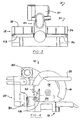
- FIGS 17 and 18 illustrate another preferred embodiment for a locking cam rod 112.
- Locking cam rod 112 is rotatably secured to each fixed fence 48 and 50 in a similar manner to locking cam rod 102.
- the difference between locking cam rod 112 and locking cam rod 102 is that locking cam rod 112 includes a longitudinally extending shaft 114 having a continuously extending cam lobe 116 disposed along its entire length.
- the remainder of locking cam rod 11 and the operation of locking cam rod 112 is the same as that described above for locking cam rod 102.
- the length of cam lobe 116 which engages movable fences 32 and 34 will depend upon the lateral positioning of moveable fences 32 and 34 along their respective fixed fences 48 and 50.
- FIG 19 illustrates a fence assembly 130 according to another embodiment of the present invention.
- Fence assembly 130 is similar to fence assembly 30 but it does not include pivotable flaps 60.
- fence assembly 130 includes a pair of movable fences 132 and 143 incorporating a raised portion 136.
- a raised portion 136 is formed generally at the saw blade end of moveable fences 132 and 134, with the edge of each raised portion 136 sloping generally downward toward saw blade 16 and table assembly 14.
- Such raised portions 136 are sized and configured, as is illustrated schematically in Figure 20, so that it engages interferingly blade guard 18 if blade guard 18 and saw blade 16 are moved from their rear clear positions to their cutting position when in substantially all of the cutting set-up modes or configurations of which sliding compound mitre saw 10 is capable.
- raised portions 136 of movable fences 132 and 134 provide an increased vertical workpiece supporting face or surface, which allows the operator to properly support a relatively tall or thick workpiece.
- Such increased-height workpiece-supporting capability- is especially advantageous when cutting thick stock, crown mouldings, base boards, or other such relatively tall workpiece shapes, orientations or configurations.
- Single fixed clamping arrangement 66 or single fixed clamping arrangement 100 can be utilised with movable fences 132 and 143 in a similar manner as that described above for movable fences 32 and 34 in order to laterally secure movable fences 132 and 134 in their selected positions.
- the rear face 176 of tongue portion 162 is preferably provided with an elongated anti-removal groove or slot 178 extending laterally there along, as shown in Figures 8b and 20.
- Anti-removal slot 178 in movable fence 132 is aligned with clamping screw 68 such that clamping screw 68 extends into slot 178 prior to exerting any clamping load on movable fence 132.
- clamping screw 68 is loosened to the point of releasing the clamping load on movable fence 132 but still in engagement with slot 178.
- This allows for the lateral adjustment of movable fence 132 without inadvertent removal of movable fence 132 from slot 52.
- the lateral length of slot 178 is sufficient to allow full adjustment of movable fence 132 but insufficient to allow inadvertent lateral removal of movable fence 132.
- clamping screw 68 (see Figures 8b and 19) is loosened allowing removal of movable fence 132.
- movable fence 134 and fixed fence 50 also incorporate anti-removal slot 178 for engagement with clamping screw 68.
- Figures 21a to 21d illustrate schematically a fence position indicator 150 associated with fence assembly 30, although it is within the scope of the present invention to incorporate fence position indicator 150 into fence assembly 130 or any other type of movable fence assembly.
- Fence position indicator 150 includes an upper indicator 152 secured to movable fences 32 and 34 and a lower indicator 154 secured to fixed fences 48 and 50.
- Upper fence indicator 152 has positions marked to indicate the degree of bevel angle to which sliding compound miter saw 10 is to be or has been adjusted.
- Lower fence indicator 154 has positions marked to indicate the degree of miter angle to which miter saw 10 is to be or has been adjusted.
- the 30° mark on upper indicator 152 is aligned with the 00 mark on lower indicator 154.
- the 45° mark on lower indicator 154 is aligned with the 0° mark on upper indicator 152.
- the 30° mark on upper indicator 152 is aligned with the 45°" on lower indicator 154.
- a mechanism for releasably holding movable fences 32 and 34 when movable fences 32 and 34 are located in one or more of the most popular bevelling and/or mitering positions can be accomplished by providing movable fences 32 and 34 with one or more indentations 160 extending along the front face of tongue 62, as shown in Figure 5. Then by incorporating a spring loaded check ball assembly 162, as shown in Figure 8a, positioned in fixed fences 48 and 50 at the proper locations, movable fences 32 and 34 will be releasably held at the various positions of movable fences 32 and 34.
- While the present invention has been described for exemplary purposes as being incorporated into sliding compound miter saw 10, it is within the scope of the present invention to incorporate the movable fence assemblies of the present invention into compound miter saws, chop saws, radial arm saws, table saws, dado saws, spindle shapers, sanders or other types of powered or unpowered devices that could benefit from the selective adjustment of the distance between the fence and the working tool.
Description
- The present invention relates to a compound miter saw or other power operated equipment or machinery utilising a cutter for performing working operations on a workpiece. More particularly, the present invention relates to improvements in an adjustable fence assembly for such power operated equipment, with the fence assembly having a fixed and a pair of movable fences for selectively adjusting the gap between the cutter and the movable fences in order to allow sufficient clearance for performing various operations on a workpiece when the equipment is in any of a number of different cutting or working modes.
- Such an adjustable fence assembly is known for example from US-A-5,297,463.
- Saws and other apparatus designed for cutting or performing other working operations on a workpiece typically require a workpiece-supporting fence in order to support and locate the workpiece in a proper fixed position for performing the working operation. Examples of such equipment include cross-cut compound miter saws which are adapted to allowing the user selectively to move the saw blade into any of a number of positions or modes for square cutting, miter cutting, bevel cutting, or compound miter cutting where a combination miter and bevel are cut. In addition, some operations, such as dado cutting or shaping operations, for example, require the use of saw blades or other cutting or working devices of different shapes or sizes to be substituted for one another in order to perform the desired operation on the workpiece, whether the workpiece is composed of wood, plastic, metal other materials.
- In order to accommodate these widely varied working operations, the workpiece-supporting fence is frequently required to be at least partially adjustable in order to vary selectively the gap or space between the saw blade or cutter and the workpiece-supporting fence, thus selectively providing clearance for the saw blade, cutter, or other device performing the working operation on the workpiece. If such adjustability were not available, a relatively large permanent gap would have to be provided between the fixed fence and the saw blade or cutter in order to accommodate the widely varying range of movement, position, or size of the saw blade, cutter, or other working device.
- In order to address the above-discussed problems associated with providing clearance for the cutter and support for the workpiece with the incorporation of a movable fence having an adjustable clearance gap, a variety of fence-adjusting arrangements have previously been provided. However, many of such prior fence-adjusting arrangements have suffered various disadvantages, including difficulty in maintaining proper alignment between the stationary fence and the movable fence in wide-gap positions, inconvenience in performing fence adjustment operations, the possibility of inadvertently misplacing a removable fence, lack of adequate support for relatively tall or thick workpieces, or other similar disadvantages. Thus, the need has arisen for an adjustable fence assembly for compound miter saws, or other power equipment requiring fence adjustability, which reduces or substantially overcomes these disadvantages, as well as providing improved ease of operation, economy in manufacturing, and other advantages that will become readily apparent to those skilled in the art from the discussion below.
- An embodiment of the present invention provides, an improved adjustable workpiece supporting fence assembly includes a pair of movable fences laterally movably interconnected with a fixed fence which is secured to a base of the device in which it is employed. The pair of movable fences are disposed on opposite sides of a saw blade, a workpiece cutter or other such device for performing a working operation on a workpiece. Each movable fence is independently movable, and is selectively and laterally movably interconnected with the fixed fence on opposite sides of the work performing blade or cutter. Each is also laterally spaced from the other movable fence located on the opposite side of the blade or cutter. The base or other portion of the device in one preferred form of the invention supports the fixed fence having a fence guide fixedly disposed on opposite sides of the blade or cutter with a laterally extending slot formed in each of the fence guides. The laterally-extending slots which preferably have spaced opposite internal walls therein are adapted to receive a laterally-extending tongue portion on a respective one of the pair of movable fences. The tongue is slidably received within the respective slot for selective adjustable lateral movement of the movable fences toward and away from the blade or cutter.
- In the above described preferred embodiment of the present invention, a single fixed clamping arrangement is interconnected with the fixed fence on each side of the saw blade or cutter. Each single fixed clamping arrangement releasably and clampingly urges the tongue on the respective movable fence against the front wall of the laterally-extending slot at any of a number of adjusted positions therein.
- The single fixed clamping arrangement includes a longitudinally extending clamping rod positioned generally parallel to each slot. The clamping rod incorporates a continuous locking lobe or a plurality of locking lobes such that the rotation of the clamping rod causes the locking lobe or lobes to clamp the movable fence against the front wall of the slot in the respective fence guide.
- According to a first aspect of the present invention there is provided a fence system for a power tool comprising:
- a first fixed fence associated with a base of said power tool, said first fixed fence being disposed on one side of a working tool (16) of said power tool,
- a first moveable fence being interconnected with said first fixed fence, characterised in that said system additionally comprises first cam rod disposed between said first fixed fence and said first moveable fence, said first cam rod being operable to clamp said first moveable fence against said first fixed fence upon rotation of said first cam rod.
-
- In a preferred embodiment said first can rod comprises a plurality of cam lobes, at least one of said cam lobes of said first cam rod being operable to clamp said first moveable fence against said first fixed fence upon rotation of said first cam rod.
- In an alternative preferred embodiment said first cam rod includes a longitudinally extending cam lobe operable to clamp said first moveable fence against said first fixed fence upon rotation of said first cam rod.
- Preferably said first fixed fence is disposed on one side of said working tool such that a first gap is created between a first portion of said adjustable fence and said working tool and a first gap filling flap is pivotally secured to said first moveable fence and operative to at least partially fill said first gap.
- The fence system may additionally comprise first means for indicating a relative position of said first moveable fence in relation to said first fixed fence and may also additionally comprise means for locating the relative position of said first fences to reflect a predetermined orientation of said working tool.
- Preferably, the fence system additionally includes anti-removal means for inhibiting removal of said first moveable fence from said first fixed fence. The anti-removal means may include a clamping screw threadably engaging said first fixed fence, said clamping screw being threadably moveable into and out of abutting engagement with said first moveable fence. Alternatively, said anti-removal means may includes a plate secured to said first fixed fence, said plate engaging a slot formed in said first moveable fence.
- The fence system according to the present invention may additionally comprise a second fixed fence associated with said base of said power tool, said second fixed fence being disposed on an opposite side of the working tool of said power tool,
- a second moveable fence being interconnected with said second fixed fence, and
- a second cam rod disposed between said second fixed fence and said second moveable fence, said second cam rod being operable to clamp said second moveable fence against said second fixed fence upon rotation of said second cam rod.
-
- The second fixed and moveable fences may have any of the features discussed above in relation to the first fixed and moveable fences.
- According to a further aspect of the present invention there is provided a device for forming working operations on a workpiece, said device comprising a motor, a working tool associated with a base and drivingly connected to said motor, said device further comprising an adjustable fence assembly as discussed above.
- The present invention will be further described with reference to the accompanying drawings in which:
- Figure 1 is a front perspective view of an embodiment of a sliding compound miter saw in accordance with the present invention;
- Figure 2 is a front elevational view of the sliding 5 compound miter saw shown in Figure 1;
- Figure 3 is a rear elevational view of the sliding compouind miter saw shown in Figures 1 and 2;
- Figure 4 is a side elevational view of the sliding compound miter saw shown in Figures 1 to 3;
- Figure 5 is a perspective view of an adjustable fence assembly in accordance with the present invention illustrating one side of the adjustable fence assembly exploded and the other side in the assembled condition;
- Figure 6 is a schematic plan view diagram of the sliding compound miter saw of Figures 1 to 4 illustrating schematically the position of the saw blade relative to the adjustable fence in a miter cutting position and a straight cross cut position;
- Figure 7 is a schematic diagram, similar to that of Figure 6, but shown in an elevational view and illustrating the adjustable fence assembly shown in a bevel cutting condition and a straight cut position;
- Figure 8a is a partial cross-sectional view of the adjustable fence assembly illustrating the single locking mechanism and anti-removal system according to the present invention;
- Figure 8b is a view similar to 8a but showing an anti-removal system according to another embodiment of the present invention;
- Figure 9 is a schematic front perspective view of the adjustable fence assembly shown prior to the saw blade or cutter providing the minimum allowable clearance between the two gap-filling flaps;
- Figure 10 is a front elevational view, partially in cross section, of one of the fence guides of the adjustable fence assembly illustrating the fixed fence pad according to the present invention;
- Figure 11 is an enlarged plan view, partially in cross-section, of the engagement between the fixed fence pad and the movable fence according to the present invention;
- Figure 12 is a schematic diagram, looking from the rear of the saw, depicting the fully retracted and partially extended positions of the movable fences;
- Figure 13 is a schematic diagram similar to Figure 7 illustrating a single locking mechanism according to another embodiment of the present invention;
- Figure 14 is a front elevational view of the cam locking bar shown in Figure 13;
- Figure 15 is a cross-sectional view illustrating the shape of the cam. locking bar shown in Figures 13 arid 14;
- Figure 16 is a partial cross-sectional view similar to Figure 8a but illustrating the single locking mechanism shown in Figure 13;
- Figure 17 is a front elevational view of a cam locking bar according to another embodiment of the present invention;
- Figure 18 is a cross-sectional view illustrating the shape of the cam locking bar shown in Figure 16;
- Figure 19 is a schematic front perspective view similar to Figure 5 of the adjustable fence according to another embodiment of the present invention;
- Figure 20 is a schematic illustration of an interfering relationship of the saw blade guard with the movable fence of the work-supporting fence assembly for alerting the operator that the movable fence of the fence assembly has not been properly adjusted for the operation being performed;
- Figure 21a is a front elevational view of an adjustable fence assembly incorporating a fence position indicator in accordance with the present invention;
- Figure 21b is a view similar to Figure 21a but showing the fence assembly of the present invention adjusted for a 30° bevel cut;
- Figure 21c is a view similar to Figure 21a but showing the fence assembly of the present invention adjusted for a 45° miter cut; and
- Figure 21d is a view similar to Figure 21a but showing the fence assembly of the present invention adjusted for a compound miter cut of a 30° bevel cut and a 45° miter cut.
-
- Referring now to the drawings in which like reference numerals designate like or corresponding parts throughout the several views, there is shown in Figures 1 to 12 an example of a sliding compound miter saw incorporating an adjustable fence assembly according to the present invention, shown merely for the purposes of illustration, and designated generally by the
reference numeral 10. The principles of the adjustable fence according to the present invention are also applicable to other types of powered or unpowered equipment for performing an operation on a workpiece. Such equipment includes, but is not limited to, dado saws, spindle shapers or sanders, or other types of powered or unpowered devices that would benefit from selective adjustment of the gap or spacing in the fence assembly in order to accommodate different sizes or positions of tooling, or to perform various different workpiece working operations. - Referring primarily to Figures 1 to 4, sliding compound miter saw 10 includes a
base assembly 12, including atable assembly 14, which is preferably rotatable in order to accommodate the various cutting positions discussed below. Miter saw 10 also includes asaw blade 16, ablade guard 18, amotor 20 drivingly connected to sawblade 16, and ahandle 22.Handle 22 assists the operator in movingsaw blade 16 andblade guard 18 from a clear position free of aworkpiece 24 to a cutting position withsaw blade 16 in cutting engagement withworkpiece 24. - A fence assembly, as best seen in Figures 1 to 5 and indicated generally by the
reference numeral 30, is interconnected withbase 12 and extends laterally acrosstable assembly 14, against which workpiece 24 is position and supported for performing a cutting operation thereon. According to an embodiment of the present invention,fence assembly 30 includes a first and a secondmovable fence movable fence movable fences saw blade 16 to perform a cutting operation completely throughworkpiece 24, regardless of the mode or type of cutting operation being performed. As is discussed in more detail below,movable fences saw blade 16 in order to allow the operator to selectively adjust the clearance gap therebetween and thus accommodate the particular cutting operation being performed. - As is illustrated schematically in Figures 6 and 7, the exemplary sliding compound miter saw 10 depicted in the drawings may be used in a number of different cutting modes or positions. In Figure 6, a schematic plan view illustrates generally the position of
saw blade 16 relative tobase assembly 12 andfence assembly 30 when performing a straight sliding or straight miter-cutting operation. Such straight, square, sliding cutting operations are schematically illustrated by the position ofsaw blade 16 shown in solid lines in Figure 6. Themovable fences saw blade 16 and the twomovable fences saw blade 16 to be moved into the cutting position along a single, vertical plane, substantially perpendicular to both the front face offence assembly 30 and the upper face oftable assembly 14. To permit miter cutting, as illustrated schematically in phantom lines in Figure 6,movable fence 32 is preselectively adjusted, as indicated in phantom by reference numeral 32a, to increase the clearance gap betweensaw blade 16 and movable fence 32a, in order to provide sufficient clearance for saw blade 16a and the associated components. - Figure 7 illustrates
saw blade 16 andfence assembly 30 in a schematic elevational view, showing the position ofsaw blade 16 andmovable fences saw blade 16 andmovable fence 32 are shown in phantom lines, as indicated by reference numeral 16b and 32b, respectively, for performing bevel cuts on'workpiece 24. The plane of movement of saw blade 16b is generally perpendicular to the face offence assembly 30, but can be selectively oriented at a bevel angle with respect totable assembly 14. Again,fence 32 can be adjusted to a predetermined position, as shown in phantom at 32b, to accommodate the bevel angle selected for saw blade 16b. - Although not specifically illustrated in the drawings, one skilled in the art will readily recognise, from the exemplary positions diagrammatically illustrated in Figures 6 and 7, that the miter-cutting operation can be combined with the bevel-cutting operation in order to perform compound mitering. In a compound mitered cut, saw
blade 16 moves in a plane which is not perpendicular either to the front face offence assembly 30 or to the upper face oftable assembly 14. In addition, although not specifically illustrated in the drawings, it can readily be recognised, from the exemplary position illustrated diagrammatically in Figures 6 and 7, that the miter-cutting operation and the bevel-cutting operation can be performed by anglingsaw blade 16 in the opposite direction from that which is illustrated and then selectively adjusting movable fence 34 (but to the right in Figures 6 and 7) in a manner similar to that shown formovable fence 32. - Thus, sliding compound miter saw 10 shown for purposes of illustration in the drawings is capable of at least four general types of cutting operations, to which reference is made herein as sliding, miter-cutting, bevel-cutting and compound miter-cutting operation. The miter-cutting, bevel-cutting and compound miter-cutting operations can be performed by angling
saw blade 16 in either direction from the sliding operation due to the incorporation ofmovable fences saw blade 16. Literally, an infinite compound adjustability of the relative position and orientation ofsaw blade 16 relative to bothtable assembly 14 andfence assembly 30 can be accomplished in the present invention by way of a compound pivot and slide mounting mechanism referred to generally asreference numeral 40 in Figures 1, 3 and 4. Compound pivot and slide mountingmechanism 40 can be any of a number of well-known pivot and bevel mounting and support mechanisms which also allowsaw blade 16 andblade guard 18 to be pivotally and slidingly moved from a rear, raised, clear position to a lowered or cutting position, once miter saw 10 is adjusted to the desired operating mode, in order to perform a cutting operation onworkpiece 24 by loweringsaw blade 16 intoworkpiece 24 and then movingsaw blade 16 longitudinally throughworkpiece 24. - In order to allow a complete cut-through operation to be performed on
workpiece 24 bysaw blade 16,fence assembly 30 must be capable of selective adjustment in order to preadjust the lateral clearance gap or spacing betweensaw blade 16 and the twomovable fences workpiece 24. In accordance with a preferred form of the present invention as best shown in Figure 5, the adjustability offence assembly 30 is accomplished in part by securing a fence-supportingmember 42 tobase assembly 12. Fence-supportingmember 42, as shown in figures 5 and 8, is a separate component fixedly secured tobase assembly 12 by a plurality ofbolts 44, and includes an interconnectingportion 46 extending laterally across a clearance gap, behindmovable fences fences workpiece 24. Fence-supportingmember 42 is fixedly secured to, or interconnected with,base assembly 12 with its fixedfences - As seen in Figures 8 through 12, fixed
fences member 42 preferably include aslot 52 defined by a first or frontinternal wall 54 spaced away from a second or rearinternal wall 56, in order to form a space therebetween extending laterally along both fixedfences saw blade 16. Eachmovable fence upper portion 58, an optional spring biased gap-fillingflap 60, and atongue portion 62 slidingly received within arespective slot 52, with thelower face 107 of eachupper portion 58 slidingly engaging fence-supportingmember 42. The frontexternal faces 63 of fence-supportingmember 42 and front faces 67 of eachmovable fence - Prior to performing a cutting operation on
workpiece 24, the minimum clearance between gap-fillingflaps 60 must first be set. This procedure begins, as shown in Figure 9, with eachmovable fence stop 61 on eachmovable fence stop 64 located on each fixedfence 48 and 50 (see also Figure 5). In this position, both gap-fillingflaps 60 are biased by a spring (not shown) to their lowered position eliminating the gap betweenmovable fences blade 16 is moved to cut through gap-fillingflaps 60, which are manufactured from easily cuttable material, such as ABS, nylon or any other rigid plastic to provide the minimum clearance formovable fences Flaps 60 could also be made form a non-ferrous material such as aluminium if clearance forsaw blade 20 is provided in the initial design of these flaps. - In order selectively to secure each
movable fence fixed clamping arrangement 66 is preferably provided for releasably fixing the position of eachmovable fence fence fixed clamping mechanism 66 will be described in relation tomovable fence 32 and fixedfence 48. It is to be understood that anidentical clamping mechanism 66 can be associated withmovable fence 34 and fixedfence 50 of the present invention. Singlefixed clamping mechanism 66 preferably includes a clampingscrew 68 threadably engaging and movable within a threadedopening 70 in fixedfence 48. Clampingscrew 68 is selectively rotatable by way of amanual knob 72 in order to threadablyadvance clamping screw 68 towardtongue portion 62 and to clampingly and forcibly urgetongue portion 62 against frontinternal wall 54 ofslot 52 as shown in Figure 8A. Singlefixed clamping mechanism 66 properly positionsmovable fence 32 due to the incorporation of an integrally machinedpad 74 located on fixedfence 48 and a corresponding integrally machinedsurface 76 located onmovable fence 32 as best illustrated in Figures 5, 8a, 10 and 11. Machinedpad 74 is located on the innermost end of fixedfence 48 withinslot 52 and, in the preferred embodiment, extends a distance of approximately 3cm (1.20) inches. Machinedsurface 76 extends along the entire inside length ofmovable fence 32, although it is within the scope of the present invention to provide a smaller machinedsurface 76 which would be located ion the inside end ofmoveable fence 32. This smaller machinedsurface 76 would be similar to and designed to mate with machinedpad 74. Thus, whenmovable fence 32 is moved to its innermost position, as shown in solid lines of Figure 12, machinedpad 74 engages machinedsurface 76, as shown in Figure 11, in order to insure that thefront face 67 ofmovable fence 32 is vertically aligned and flush with the frontexternal face 63 of fixedfence 48. Machinedpad 74 and machinedsurface 76 are machined to a tight tolerance in order to reduce the amount of clearance between thepad 74 andsurface 76 to approximately 0.15mm ± 0.05mm (.006 inches ± .002 inches) when they are engaged. Thus, the clearance betweentongue portion 62 ofmovable fence 32 andslot 52 of fixedfence 48 is reduced to approximately 0.15mm (.006 inches)which eliminates the need to incorporate a clamping member in the area adjacent to the innermost portion ofmovable fence 32. The small clearance between machinedpad 74 and machinedsurface 76 preventing the rearward movement ofmovable fence 32 thus keeping faces 63 and 67 flush and vertically aligned. As shown in Figures 8A and 8B,movable fence 32 is clamped in position by rotatingknob 72 which threadably advances clampingscrew 68 towardtongue portion 62 to clampingly and forcibly urgetongue portion 62 against frontinternal wall 54 ofslot 52. The opposite end ofmovable fence 32 is held in position by the engagement of machinedpad 74 and machinedsurface 76 as detailed above.. - The engagement between machined
pad 74 of fixedfence 48 and machinedsurface 76 ofmovable fence 32 will continue asmovable fence 32 is moved outwards until the proximate centre ofmovable fence 32 generally aligns with the centre line of clampingscrew 68. At this point in the adjustment ofmovable fence 32 and throughout the remainder of the outward adjustment ofmovable fence 32, the single fixed clamping mechanism incorporating clampingscrew 68 provides sufficient clamping without the engagement ofpad 74 andsurface 76 due to the now centralised location of clampingscrew 68 to positionmovable fence 32 flush and vertically aligned with fixedfence 48 as illustrated in Figure 8. - In order to minimise the possibility of inadvertent removal of
movable fence 32 from fixedfence 48 during position adjustments, machinedsurface 76 oftongue portion 62 is preferably provided with an elongated anti-removal groove orslot 78 extending laterally theralong, as shown in Figures 5 and 8a.Anti-removal slot 78 inmovable fence 32 is aligned with a clampingplate 79 which is fixedly secured to fixedfence 48 by a plurality ofbolts 81. Clampingplate 79 extends intoslot 78 to prevent vertical removal ofmovable fence 32. Removal ofmovable fence 32 can be accomplished by the lateral movement ofmovable fence 32 until the movable fence is totally removed. Clampingplate 79 also resists the upward movement ofmovable fence 32 due to the reaction of spring loaded gap-fillingflap 60. - Thus, when adjustment of
movable fence 32 is required, clampingscrew 68 is loosened to the point of releasing the clamping load onmovable fence 32. This allows for the lateral adjustment ofmovable fence 32 without inadvertent removal ofmovable fence 32 fromslot 52. When it is desired to removemovable fence 32 for repair, replacement or cleaning, however, clamping screw 68 (see Figure 8a) is loosened allowing removal ofmovable fence 32 by movingmovable fence 32 laterally to disengage clampingplate 79 fromslot 78. - As indicated above,
movable fence 34 and fixedfence 50 also incorporate singlefixed clamping arrangement 66 in order to securemovable fence 34 to fixedfence 50 on the opposite side ofsaw blade 16. - Also as noted above, each
movable fence flap 60. The location and function of gap-fillingflap 60 will be described in relation tomovable fence 32 and fixedfence 48. It is to be understood that an identical gap-fillingflap 60 is associated withmovable fence 34 and fixedfence 50 on the opposite side ofsaw blade 16 in the present invention.Flap 60 is pivotably mounted at 81 tomovable fence 32 within arecess 80 provided at the inner end ofmovable fence 32. Gap-fillingflap 60 is biased to its lower position, as shown in Figure 5 in solid lines, by a spring (not shown). As described above in reference to Figure 9, when gap-fillingflap 60 is located in its lowered position, the minimum gap betweenmovable fence 32 and sawblade 16 is initially provided. As shown in Figures 8 and 9,flap 60 is provided with atab 82 which rides in aslot 84 longitudinally extending along fixedfence 48 generally parallel to slot 52. The width offlap 60, the depth ofrecess 80, the location and thickness oftab 82 and the thickness and width ofslot 84 are selected to position the outer surface offlap 60 in a vertically aligned generally flush location withfaces 63 of fixedfence 48 and faces 67 ofmovable fence 32.Flap 60 can be moved from its lowered position, as shown in Figure 9, due to the engagement of a ramped orangular surface 86 located on fixedfence 48 with a correspondingangular surface 88 located onflap 60. Asmovable fence 32 is moved laterally from its innermost position toward its outermost position, surfaces 86 and 88 react to pivotflap 60 upwardly, as shown in phantom in Figure 12. - When
movable fences movable flaps 60 are restricted from pivoting due to the engagement oftabs 82 with blind ends 90 ofslots 84. The movement ofmovable fences tabs 82 from their respectiveblind end 90 allowing for the pivoting of gap-fillingflaps 60. As indicated above,movable fence 34 also incorporates a respective gap-fillingflap 60 in order to minimise the gap betweenmovable fence 34 and sawblade 16. The above description applies equally well to-movable fence 34andfixed fence 50. - Figures 13 through 16 illustrate another embodiment of a signal fixed
clamping arrangement 100 for releasably fixing the position of eachmovable fence fence movable fence 32 and fixedfence 48. It is to be understood that an identicalfixed clamping mechanism 100 may be associated withmovable fence 34 and fixedfence 50 of the present invention. Singlefixed clamping arrangement 100 preferably includes a lockingcam rod 102 rotatably connected to fixedfence 48 as shown in Figure 13. Lockingcam rod 102, as shown in Figures 14 and 15, includes alongitudinally extending shaft 104 having a plurality ofcam lobes 106 disposed along its length. The end ofshaft 104 which extends beyond the outside of fixedfence 48 is bent at an approximately 90° angle to provide anactuation handle 108 formechanism 100.Cam rod 102 is disposed between rearinternal wall 56 and ofslot 52 andtongue portion 62 ofmovable fence 32 as shown in Figure 16. When cam lobes 106 are located in a generally vertical position,movable fence 32 may slide relative to fixedfence 48 because there is no engagement withcam rod 102. Whencam rod 102 is rotated approximately 90°,cam lobes 106 move from a vertical position to a horizontal position. During this movement from a vertical position to the horizontal position,cam lobes 106 cammingly engage an angular surface or ramp 110 located ontongue portion 62 to clamp thelower face 107 ofupper portion 58 ofmovable fence 32 against fence-supportingmember 42 and the front face 109 oftongue portion 62 against frontinternal wall 54 of fixedfence 48 thus securingmovable fence 32. The height ofcam lobes 106 is selected to be greater than the gap betweentongue portion 62 and fixedfence 48, thus producing the required clamping load. The number ofcam lobes 106 which engagemovable fence 32 will depend upon the relative lateral positioning ofmovable fence 32 along fixedfence 48. - As indicated above,
movable fence 34 and fixedfence 50 can also incorporate singlefixed clamping arrangement 100 in order to securemovable fence 34 to fixedfence 50 on the opposite side ofsaw blade 16. The above description applies equally well tomovable fence 34 and fixedfence 50. - Figures 17 and 18 illustrate another preferred embodiment for a locking cam rod 112. Locking cam rod 112 is rotatably secured to each fixed
fence cam rod 102. The difference between locking cam rod 112 and lockingcam rod 102 is that locking cam rod 112 includes alongitudinally extending shaft 114 having a continuously extendingcam lobe 116 disposed along its entire length. The remainder of lockingcam rod 11 and the operation of locking cam rod 112 is the same as that described above for lockingcam rod 102. The length ofcam lobe 116 which engagesmovable fences moveable fences fences - Figure 19 illustrates a fence assembly 130 according to another embodiment of the present invention. Fence assembly 130 is similar to
fence assembly 30 but it does not include pivotable flaps 60. In place offlaps 60, fence assembly 130 includes a pair ofmovable fences 132 and 143 incorporating a raisedportion 136. Here, a raisedportion 136 is formed generally at the saw blade end ofmoveable fences portion 136 sloping generally downward towardsaw blade 16 andtable assembly 14. Such raisedportions 136 are sized and configured, as is illustrated schematically in Figure 20, so that it engagesinterferingly blade guard 18 ifblade guard 18 and sawblade 16 are moved from their rear clear positions to their cutting position when in substantially all of the cutting set-up modes or configurations of which sliding compound mitre saw 10 is capable. - In addition, as can be seen in Figure 19, raised
portions 136 ofmovable fences fixed clamping arrangement 66 or singlefixed clamping arrangement 100 can be utilised withmovable fences 132 and 143 in a similar manner as that described above formovable fences movable fences - In order to minimise the possibility of inadvertent removal of
movable fence 132 from fixedfence 48 ormovable fence 134 from fixedfence 50 during position adjustments, therear face 176 oftongue portion 162 is preferably provided with an elongated anti-removal groove or slot 178 extending laterally there along, as shown in Figures 8b and 20.Anti-removal slot 178 inmovable fence 132 is aligned with clampingscrew 68 such that clampingscrew 68 extends intoslot 178 prior to exerting any clamping load onmovable fence 132. - Thus, when adjustment of
movable fence 132 is required, clampingscrew 68 is loosened to the point of releasing the clamping load onmovable fence 132 but still in engagement withslot 178. This allows for the lateral adjustment ofmovable fence 132 without inadvertent removal ofmovable fence 132 fromslot 52. As seen in Figure 20, the lateral length ofslot 178 is sufficient to allow full adjustment ofmovable fence 132 but insufficient to allow inadvertent lateral removal ofmovable fence 132. When it is desired to removemovable fence 132 for repair, replacement or cleaning, however, clamping screw 68 (see Figures 8b and 19) is loosened allowing removal ofmovable fence 132. As indicated above,movable fence 134 and fixedfence 50 also incorporateanti-removal slot 178 for engagement with clampingscrew 68. - Figures 21a to 21d illustrate schematically a
fence position indicator 150 associated withfence assembly 30, although it is within the scope of the present invention to incorporatefence position indicator 150 into fence assembly 130 or any other type of movable fence assembly. -
Fence position indicator 150 includes anupper indicator 152 secured tomovable fences lower indicator 154 secured to fixedfences Upper fence indicator 152 has positions marked to indicate the degree of bevel angle to which sliding compound miter saw 10 is to be or has been adjusted.Lower fence indicator 154 has positions marked to indicate the degree of miter angle to which miter saw 10 is to be or has been adjusted. Thus, by aligning the proper bevelling mark onupper fence indicator 152 with the proper mitering mark onlower fence indicator 154, the proper fence position formovable fences Fence position indicator 150 can also be incorporated withmovable fences - For example, for making solely a bevel cut of 30°, as shown in Figure 21b, the 30° mark on
upper indicator 152 is aligned with the 00 mark onlower indicator 154. For making solely a miter cut of 45°, as shown in Figure 21c, the 45° mark onlower indicator 154 is aligned with the 0° mark onupper indicator 152. For a compound cutting operation for a bevel cut of 30° in combination with a miter cut of 45°, as shown in Figure 21d, the 30° mark onupper indicator 152 is aligned with the 45°" onlower indicator 154. - It may be advantageous to include a mechanism for releasably holding
movable fences movable fences movable fences more indentations 160 extending along the front face oftongue 62, as shown in Figure 5. Then by incorporating a spring loadedcheck ball assembly 162, as shown in Figure 8a, positioned in fixedfences movable fences movable fences - While the present invention has been described for exemplary purposes as being incorporated into sliding compound miter saw 10, it is within the scope of the present invention to incorporate the movable fence assemblies of the present invention into compound miter saws, chop saws, radial arm saws, table saws, dado saws, spindle shapers, sanders or other types of powered or unpowered devices that could benefit from the selective adjustment of the distance between the fence and the working tool.
Claims (28)
- A fence system for a power tool comprising:characterised in that said system additionally comprises a first cam rod (104, 114) disposed between said first fixed fence (48) and said first moveable fence (32), said first cam rod being operable to clamp said first moveable fence against said first fixed fence upon rotation of said first cam rod.a first fixed fence (48) associated with a base (12) of said power tool, said first fixed fence being disposed on one side of a working tool (16) of said power tool,a first moveable fence (32,132) being interconnected with said first fixed fence (48),
- A fence system according to claim 1 characterised in that said first can rod (104) comprises a plurality of cam lobes (106), at least one of said cam lobes of said first cam rod being operable to clamp said first moveable fence (32) against said first fixed fence (48) upon rotation of said first cam rod.
- A fence system according to claim 1 characterised in that said first cam rod (114) includes a longitudinally extending cam lobe (116) operable to clamp said first moveable fence (32) against said first fixed fence (48) upon rotation of said first cam rod.
- A fence system according to any one of the preceding claims characterised in that said first fixed fence (48) is disposed on one side of said working tool (16) such that a first gap is created between a first portion of said adjustable fence and said working tool and a first gap filling flap (60) is pivotally secured to said first moveable fence (32) and operative to at least partially fill said first gap.
- A fence system according to any one of the preceding claims characterised in that said system additionally comprises first means for indicating (150) a relative position of said first moveable fence (32) in relation to said first fixed fence (48).
- A fence system according to any one of the preceding claims characterised in that said system additionally comprises means for locating (150) the relative position of said first fences (32,48) to reflect a predetermined orientation of said working tool (16).
- A fence system according to any one of the preceding claims characterised in that said system additionally includes anti-removal means (68,79) for inhibiting removal of said first moveable fence (32) from said first fixed fence (48).
- A fence system according to claim 7 characterised in that said anti-removal means includes a clamping screw (68) threadably engaging said first fixed fence (48), said clamping screw being threadably moveable into and out of abutting engagement with said first moveable fence (32,132).
- A fence system according to claim 7 characterised in that said anti-removal means includes a plate (79) secured to said first fixed fence (48), said plate engaging a slot (78) formed in said first moveable fence (32).
- A fence system according to any one of the preceding claims characterised in that said first moveable fence (132) includes a raised portion disposed at said second end of said moveable fence, said raised portion co-acting with said first fixed fence to align respective front faces of said first fixed fence and said first moveable fence.
- A fence system according to claim 5 characterised in that said means for indicating (150) includes a first indicator (152,154) located on one of said first fixed fence (48) and said first moveable fence (32,132).
- A fence system according to claim 6 characterised in that said means for indicating (150) includes a first indicator (152,154) located on one of said first fixed fence (48) and said first moveable fence (32,132) and said means for locating the relative position of said first fences includes a second indicator (152,154) located on the other of said first fixed fence (48) and said first moveable fence (32,132), said second indicator co-acting with said first indicator to locate the position of said first moveable fence relative to said first fixed fence at said predetermined orientation of said working tool (16).
- A fence system according to claim 6 characterised in that said means for indicating (150) includes a first indicator (152,154) located on one of said first fixed fence (48) and said first moveable fence (32,132) and said means for locating the relative position of said first fences includes a second indicator (152,154) located on the other of said first fixed fence (48) and said first moveable fence (32,132), said second indicator co-acting with said first indicator to locate the position of said first moveable fence relative to said first fixed fence for a predetermined bevel angle and a predetermined mitre angle.
- A fence system according to any one of the preceding claims characterised in that it additionally comprises a member (162) releasably holding said first moveable fence in a predetermined position in relation to said first fixed fence.
- A fence system according to any one of claims 1 to 14 characterised in that said adjustable fence further comprises;a second fixed fence (50) associated with said base (12) of said power tool, said second fixed fence being disposed on an opposite side of the working tool (16) of said power tool,a second moveable fence (34) being interconnected with said second fixed fence (50), anda second cam rod (104, 114) disposed between said second fixed fence (50) and said second moveable fence (34), said second cam rod being operable to clamp said second moveable fence against said second fixed fence upon rotation of said second cam rod.
- A fence system according to claim 15 characterised in that said second cam rod (104) comprises a plurality of cam lobes (106), at least one of said cam lobes of said second cam rod being operable to clamp said second moveable fence (34) against said second fixed fence (50) upon rotation of said second cam rod.
- A fence system according to claim 15 characterised in that said second cam rod (114) includes a longitudinally extending cam lobe (116) operable to clamp said second moveable fence (34) against said second fixed fence (50) upon rotation of said first cam rod.
- A device according to any one of claims 15 to 17 in which said second fixed fence (50) is disposed on an opposite side of said working tool (16) such that a second gap is created between a second portion of said adjustable fence and said working tool characterised in that a second gap filling flap (60) is pivotally secured to said second moveable fence (34) and operative to at least partially fill said second gap.
- A fence arrangement according to any one of claims 15 to 18 characterised in that the arrangement additionally comprises second means (150) for indicating a relative position of said second moveable fence in relation to said second fixed fence.
- A fence system according to any one of claims 15 to 19 characterised in that said system additionally comprises means for locating (150) the relative position of said second fences (34,50) to reflect a predetermined orientation of said working tool (16).
- A fence system according to any one of claims 15 to 20 characterised in that said system additionally includes anti-removal means (68,79) for inhibiting removal of said second moveable fence (34) from said second fixed fence (50).
- A fence system according to claim 21 characterised in that said anti-removal means includes a clamping screw (68) threadably engaging said second fixed fence (50), said clamping screw being threadably moveable into and out of abutting engagement with said second moveable fence (34).
- A fence system according to claim 21 characterised in that said anti-removal means includes a plate (79) secured to said second fixed fence (50), said plate engaging a slot (78) formed in said second moveable fence (34).
- A fence system according to any one of claims 15 to 23 characterised in that said second moveable fence (134) includes a raised portion disposed at said second end of said moveable fence, said raised portion co-acting with said second fixed fence (50) to align respective front faces of said second fixed fence and said second moveable fence.
- A fence system according to claim 19 characterised in that said means for indicating (150) includes a third indicator (152,154) located on one of said second fixed fence (50) and said second moveable fence (34).
- A fence system according to claim 20 characterised in that said means for indicating (150) includes a third indicator (152,154) located on one of said second fixed fence (50) and said second moveable fence (34) and said means for locating the relative position of said second fences includes a fourth indicator (152,154) located on the other of said second fixed fence (50) and said second moveable fence (34), said fourth indicator (152,154) co-acting with said third indicator to locate the position of said second moveable fence relative to said second fixed fence at said predetermined orientation of said working tool (16).
- A fence system according to any one of claims 15 to 26 characterised in that the system additionally comprises a member (162) releasably holding said second moveable fence (34) in a predetermined position in relation to said second fixed fence (50).
- A device for forming working operations on a workpiece, said device comprising a motor (20), a working tool (16) associated with a base (12) and drivingly connected to said motor, characterised in that said device further comprises an adjustable fence assembly according to any one of the preceding claims.
Applications Claiming Priority (3)
| Application Number | Priority Date | Filing Date | Title |
|---|---|---|---|
| US08/499,339 US5755148A (en) | 1995-07-07 | 1995-07-07 | Adjustable fence for a compound miter saw |
| US499339 | 1995-07-07 | ||
| EP96304834A EP0752300B1 (en) | 1995-07-07 | 1996-07-01 | Adjustable fence for a compound miter saw |
Related Parent Applications (2)
| Application Number | Title | Priority Date | Filing Date |
|---|---|---|---|
| EP96304834.3 Division | 1996-07-01 | ||
| EP96304834A Division EP0752300B1 (en) | 1995-07-07 | 1996-07-01 | Adjustable fence for a compound miter saw |
Publications (2)
| Publication Number | Publication Date |
|---|---|
| EP0997243A1 EP0997243A1 (en) | 2000-05-03 |
| EP0997243B1 true EP0997243B1 (en) | 2002-10-02 |
Family
ID=23984891
Family Applications (3)
| Application Number | Title | Priority Date | Filing Date |
|---|---|---|---|
| EP00101756A Expired - Lifetime EP0997244B1 (en) | 1995-07-07 | 1996-07-01 | Adjustable fence arrangement for a compound miter saw |
| EP96304834A Expired - Lifetime EP0752300B1 (en) | 1995-07-07 | 1996-07-01 | Adjustable fence for a compound miter saw |
| EP00101754A Expired - Lifetime EP0997243B1 (en) | 1995-07-07 | 1996-07-01 | Adjustable fence for a compound miter saw |
Family Applications Before (2)
| Application Number | Title | Priority Date | Filing Date |
|---|---|---|---|
| EP00101756A Expired - Lifetime EP0997244B1 (en) | 1995-07-07 | 1996-07-01 | Adjustable fence arrangement for a compound miter saw |
| EP96304834A Expired - Lifetime EP0752300B1 (en) | 1995-07-07 | 1996-07-01 | Adjustable fence for a compound miter saw |
Country Status (6)
| Country | Link |
|---|---|
| US (5) | US5755148A (en) |
| EP (3) | EP0997244B1 (en) |
| CN (1) | CN1080170C (en) |
| DE (3) | DE69619028T2 (en) |
| ES (3) | ES2179799T3 (en) |
| TW (1) | TW403696B (en) |
Cited By (1)
| Publication number | Priority date | Publication date | Assignee | Title |
|---|---|---|---|---|
| CN102773883A (en) * | 2012-07-11 | 2012-11-14 | 无锡市福曼科技有限公司 | Pneumatic stopping device for wood machining device |
Families Citing this family (120)
| Publication number | Priority date | Publication date | Assignee | Title |
|---|---|---|---|---|
| US6971297B1 (en) * | 1995-10-10 | 2005-12-06 | Black & Decker Inc. | Guard and control apparatuses for sliding compound miter saw |
| DE19729552A1 (en) * | 1997-07-10 | 1999-01-14 | Reich Maschf Gmbh Karl | Stop device for miter saw |
| US6523447B2 (en) * | 1997-09-26 | 2003-02-25 | Black & Decker Inc. | Cordless chop saw |
| USD415000S (en) * | 1997-11-14 | 1999-10-12 | Hitachi Koki Co., Ltd. | Bench circular saw |
| JP3884865B2 (en) * | 1998-02-06 | 2007-02-21 | 株式会社マキタ | Tabletop circular saw |
| TW467783B (en) * | 1998-02-13 | 2001-12-11 | Black & Amp Decker Inc | Table saw |
| US6272960B1 (en) * | 1998-06-03 | 2001-08-14 | Black & Decker Inc. | Chop saw |
| KR100279566B1 (en) * | 1998-08-13 | 2001-03-02 | 배형대 | Paper Corner Decorative Punching Machine |
| US6899004B1 (en) | 1998-08-14 | 2005-05-31 | Delta International Machinery Corp. | Sawing apparatus and saw fence system |
| USD422864S (en) * | 1999-07-13 | 2000-04-18 | Black & Decker Inc. | Handle for a chop saw |
| US7044041B1 (en) * | 2000-03-13 | 2006-05-16 | Black & Decker Inc. | Miter saw |
| US8061245B2 (en) | 2000-09-29 | 2011-11-22 | Sd3, Llc | Safety methods for use in power equipment |
| US7536238B2 (en) | 2003-12-31 | 2009-05-19 | Sd3, Llc | Detection systems for power equipment |
| US7707920B2 (en) | 2003-12-31 | 2010-05-04 | Sd3, Llc | Table saws with safety systems |
| US7024975B2 (en) | 2000-08-14 | 2006-04-11 | Sd3, Llc | Brake mechanism for power equipment |
| US20020017179A1 (en) * | 2000-08-14 | 2002-02-14 | Gass Stephen F. | Miter saw with improved safety system |
| US8459157B2 (en) | 2003-12-31 | 2013-06-11 | Sd3, Llc | Brake cartridges and mounting systems for brake cartridges |
| US9927796B2 (en) | 2001-05-17 | 2018-03-27 | Sawstop Holding Llc | Band saw with improved safety system |
| US7600455B2 (en) | 2000-08-14 | 2009-10-13 | Sd3, Llc | Logic control for fast-acting safety system |
| US9724840B2 (en) | 1999-10-01 | 2017-08-08 | Sd3, Llc | Safety systems for power equipment |
| US7377199B2 (en) | 2000-09-29 | 2008-05-27 | Sd3, Llc | Contact detection system for power equipment |
| US7712403B2 (en) | 2001-07-03 | 2010-05-11 | Sd3, Llc | Actuators for use in fast-acting safety systems |
| US7836804B2 (en) | 2003-08-20 | 2010-11-23 | Sd3, Llc | Woodworking machines with overmolded arbors |
| US7210383B2 (en) | 2000-08-14 | 2007-05-01 | Sd3, Llc | Detection system for power equipment |
| US6857345B2 (en) | 2000-08-14 | 2005-02-22 | Sd3, Llc | Brake positioning system |
| US7225712B2 (en) | 2000-08-14 | 2007-06-05 | Sd3, Llc | Motion detecting system for use in a safety system for power equipment |
| US20030056853A1 (en) | 2001-09-21 | 2003-03-27 | Gass Stephen F. | Router with improved safety system |
| US6880440B2 (en) * | 2000-09-29 | 2005-04-19 | Sd3, Llc | Miter saw with improved safety system |
| US8065943B2 (en) | 2000-09-18 | 2011-11-29 | Sd3, Llc | Translation stop for use in power equipment |
| US7827890B2 (en) | 2004-01-29 | 2010-11-09 | Sd3, Llc | Table saws with safety systems and systems to mount and index attachments |
| US6334380B1 (en) * | 2000-01-24 | 2002-01-01 | Duro Machinery Corp. | Clamping device of circular saw |
| JP3925046B2 (en) * | 2000-06-29 | 2007-06-06 | 日立工機株式会社 | Tabletop circular saw |
| US6360798B1 (en) | 2000-08-11 | 2002-03-26 | Wolfcraft Gmbh | Router tables |
| US6826988B2 (en) | 2000-09-29 | 2004-12-07 | Sd3, Llc | Miter saw with improved safety system |
| US6813983B2 (en) | 2000-09-29 | 2004-11-09 | Sd3, Llc | Power saw with improved safety system |
| US20020100350A1 (en) * | 2001-01-16 | 2002-08-01 | Brazell Kenneth M. | Sliding fence for a compound miter saw |
| US7617755B2 (en) * | 2001-02-01 | 2009-11-17 | Black & Decker Inc. | Miter saw |
| US7252027B2 (en) * | 2001-02-08 | 2007-08-07 | Black & Decker Inc. | Miter saw |
| US6755107B2 (en) * | 2001-05-18 | 2004-06-29 | One World Technologies Lmt. | Miter saw having a light beam alignment system |
| US6604296B2 (en) * | 2001-08-23 | 2003-08-12 | Michael Mastrobattista | Framing speedsquare attachment |
| US6868938B2 (en) * | 2001-09-07 | 2005-03-22 | Bombardier Recreational Products Inc. | Noise-reducing engine enclosure |
| US8004664B2 (en) | 2002-04-18 | 2011-08-23 | Chang Type Industrial Company | Power tool control system |
| US6937336B2 (en) | 2002-08-15 | 2005-08-30 | Black & Decker, Inc. | Optical alignment system for power tool |
| US6854372B2 (en) * | 2002-06-04 | 2005-02-15 | William Jefferson Anthony | Enhanced miter saw |
| US20040003696A1 (en) * | 2002-06-13 | 2004-01-08 | Radda Richard Ray | Sliding miter fence |
| US20030233921A1 (en) | 2002-06-19 | 2003-12-25 | Garcia Jaime E. | Cutter with optical alignment system |
| US7228774B2 (en) * | 2002-06-21 | 2007-06-12 | Black & Decker Inc. | Adjustable cleat |
| US6994007B2 (en) * | 2002-07-09 | 2006-02-07 | Black & Decker Inc. | Chop saw |
| US6782783B2 (en) * | 2002-07-26 | 2004-08-31 | Black & Decker Inc. | Slide miter saw |
| US20040020342A1 (en) * | 2002-08-02 | 2004-02-05 | Wattenbach Brian P. | Fence protection arrangement for a slide miter saw |
| US6755108B2 (en) * | 2002-08-28 | 2004-06-29 | Black & Decker Inc. | Return mechanism for a slide miter saw |
| US20040103769A1 (en) * | 2002-09-17 | 2004-06-03 | Parks James R. | Dust collection arrangement for a miter saw |
| US20040052599A1 (en) * | 2002-09-17 | 2004-03-18 | Wattenbach Brian P. | Miter saw arrangement for increased cutting capacity |
| US7819044B2 (en) * | 2002-10-01 | 2010-10-26 | Black & Decker Inc. | Fence arrangement for a slide miter saw |
| US6830125B1 (en) * | 2002-11-04 | 2004-12-14 | F. Peter Bizlewicz | Vibratory energy dissipation and isolation with magnetically biased rolling members |
| US20060101967A1 (en) * | 2002-11-19 | 2006-05-18 | Garcia Jaime E | Greater capacity cutting saw |
| US7243587B2 (en) * | 2002-12-16 | 2007-07-17 | Black & Decker Inc. | Pivoting rear blade guard |
| US6901834B2 (en) * | 2003-09-26 | 2005-06-07 | Chin-Chin Chang | Movement adjust device for a circular saw |
| US20060101971A1 (en) * | 2004-01-30 | 2006-05-18 | Vance Roe | Miter saw workpiece stop |
| DE102005009227B4 (en) * | 2004-03-05 | 2023-06-15 | Wolfcraft Gmbh | Milling table and accessories |
| GB2426228B (en) * | 2004-04-15 | 2008-07-09 | Milwaukee Electric Tool Corp | Saw,such as a miter saw |
| AU2005202871B2 (en) * | 2004-07-07 | 2010-05-27 | Black & Decker, Inc. | Blade guard assembly for saws |
| EP1621302B1 (en) * | 2004-07-07 | 2008-05-21 | BLACK & DECKER INC. | Fence assembly for miter saws |
| CN2744453Y (en) * | 2004-07-26 | 2005-12-07 | 苏州宝时得电动工具有限公司 | Oblique saw |
| US8122802B2 (en) * | 2004-10-21 | 2012-02-28 | Lawrence Lacy | Multi-function power saw |
| JP4759276B2 (en) * | 2005-01-20 | 2011-08-31 | 日立工機株式会社 | Tabletop cutting machine |
| US8910552B2 (en) * | 2005-03-01 | 2014-12-16 | Blue Collar Ventures, L.L.C. | Movable saw apparatus and method |
| US20060236833A1 (en) * | 2005-04-25 | 2006-10-26 | Meredith Daryl S | Fence arrangement for a miter saw |
| JP4442514B2 (en) * | 2005-05-27 | 2010-03-31 | 日立工機株式会社 | Tabletop cutting machine |
| AU2007200238B9 (en) * | 2006-01-31 | 2012-06-14 | Black & Decker Inc | Saw |
| TWM302455U (en) * | 2006-03-23 | 2006-12-11 | Rexon Ind Corp Ltd | Baffle of cutting machine |
| US8549970B2 (en) * | 2006-05-25 | 2013-10-08 | Donald Jesse Stone | Power saw |
| US20080022824A1 (en) * | 2006-07-28 | 2008-01-31 | Chin-Chin Chang | Fence mounting structure for circular saw |
| TW200812766A (en) * | 2006-09-01 | 2008-03-16 | P & F Brother Ind Corp | Fastening device of blocking sheet for cutting machine |
| JP5051610B2 (en) * | 2006-11-16 | 2012-10-17 | 日立工機株式会社 | Tabletop cutting machine |
| US20090095141A1 (en) * | 2007-10-15 | 2009-04-16 | Black & Decker Inc. | Adjustable fence for a miter saw |
| JP5377945B2 (en) | 2008-03-21 | 2013-12-25 | 株式会社マキタ | Tabletop cutting machine |
| EP2248642A4 (en) * | 2008-04-21 | 2012-07-18 | Makita Corp | Jig for bench circular saw machine and bench circular saw machine |
| US8418590B2 (en) * | 2008-06-04 | 2013-04-16 | Black & Decker Inc. | Miter saws having locking assemblies for optimal positioning of cutting blades |
| US20090301277A1 (en) * | 2008-06-09 | 2009-12-10 | Aleksander Ipatenco | Saw With Moveable Material Support Surface |
| US8776656B2 (en) * | 2008-07-22 | 2014-07-15 | Gerhard Weusthof | Circular and miter box saw |
| US8266996B2 (en) * | 2008-07-24 | 2012-09-18 | Robert Bosch Gmbh | Adjustable fence assembly for a miter saw |
| US8549759B2 (en) * | 2008-07-25 | 2013-10-08 | Milwaukee Electric Tool Corporation | Adjustable shoe for a power tool |
| US8549760B2 (en) * | 2008-07-25 | 2013-10-08 | Milwaukee Electric Tool Corporation | Adjustable locking shoe |
| US9833924B2 (en) * | 2008-08-22 | 2017-12-05 | Black & Decker Inc. | Method and apparatus for automatically adjusting a miter saw fence |
| US8186257B2 (en) * | 2008-08-27 | 2012-05-29 | Robert Bosch Gmbh | Laminate flooring saw |
| CN101758292B (en) * | 2008-10-24 | 2012-07-18 | 苏州宝时得电动工具有限公司 | Cutter |
| US8424434B2 (en) * | 2009-04-28 | 2013-04-23 | Robert Bosch Gmbh | Universal fence for a power table saw |
| JP5468322B2 (en) * | 2009-07-10 | 2014-04-09 | 株式会社マキタ | Guard member fixing prevention structure for cutting machine |
| US8661956B2 (en) * | 2009-08-13 | 2014-03-04 | Robert Bosch Gmbh | Rear mounted miter saw fence |
| DE102009060787A1 (en) * | 2009-12-21 | 2011-06-22 | Michael Weinig AG, 97941 | Splitting wedge device for a saw unit |
| CN201659327U (en) | 2010-01-08 | 2010-12-01 | 南京德朔实业有限公司 | Miter saw leaning fence |
| GB201008829D0 (en) * | 2010-05-27 | 2010-07-14 | Evolution Power Tools Ltd | Mitre saw |
| US9486935B2 (en) * | 2010-11-12 | 2016-11-08 | William Niichel | Safety devices for power cutting tools |
| TW201226139A (en) * | 2010-12-28 | 2012-07-01 | Rexon Ind Corp Ltd | A saw machine fence adjustment mechanism |
| US8621970B2 (en) | 2011-01-03 | 2014-01-07 | Robert Bosch Gmbh | Miter saw with adjustable fence |
| CN102632295A (en) * | 2011-02-14 | 2012-08-15 | 力山工业股份有限公司 | Backup plate transposing device for sawing machine |
| GB2504272A (en) | 2012-07-23 | 2014-01-29 | Black & Decker Inc | A Support Preventing Tipping of a Mitre Saw |
| GB2507943A (en) | 2012-07-23 | 2014-05-21 | Black & Decker Inc | Dust removal for Saw |
| US10118308B2 (en) | 2013-10-17 | 2018-11-06 | Sawstop Holding Llc | Systems to mount and index riving knives and spreaders in table saws |
| JP6215047B2 (en) * | 2013-12-26 | 2017-10-18 | 株式会社マキタ | Tabletop cutting tool |
| US9908257B2 (en) * | 2014-09-11 | 2018-03-06 | Robert Bosch Tool Corporation | Adjustable fence assembly for a miter saw |
| CN104260151A (en) * | 2014-09-19 | 2015-01-07 | 上海锐奇工具股份有限公司 | Skew cutting saw with interchangeable left and right slide backing bars |
| CN104280245B (en) * | 2014-10-27 | 2017-09-01 | 凯迈(洛阳)机电有限公司 | Engine running-in test table and floating docking facilities and its adjustment component |
| US10442109B2 (en) | 2014-12-24 | 2019-10-15 | William Niichel | Safety device for power cutting tools |
| EP3261794B1 (en) | 2015-02-25 | 2023-02-15 | Milwaukee Electric Tool Corporation | Miter saw |
| USD796561S1 (en) * | 2015-08-25 | 2017-09-05 | Chester Bronson Andrews, III | Mitre saw fence scale |
| TWI620609B (en) * | 2015-10-15 | 2018-04-11 | 美商羅威有限公司 | Fence assembly for miter saw |
| CN105397185A (en) * | 2015-12-09 | 2016-03-16 | 桐乡力山工业有限公司 | Circular sawing machine with auxiliary baffle device |
| US9810524B2 (en) * | 2015-12-15 | 2017-11-07 | Sears Brands, L.L.C. | Power tool with optical measurement device |
| DE102016109377A1 (en) * | 2016-05-20 | 2017-11-23 | Festool Gmbh | Machine tool with a plant body |
| US10543542B2 (en) * | 2016-07-27 | 2020-01-28 | Tti (Macao Commercial Offshore) Limited | Miter saw |
| US10022887B2 (en) * | 2016-08-26 | 2018-07-17 | Johannes Hogenhout | Miter saw extendable fence attachment |
| US10640240B2 (en) | 2017-06-22 | 2020-05-05 | Hamilton Sundstrand Corporation | Thermal management system with sublimator and adsorbent bed |
| US10875109B1 (en) | 2018-04-30 | 2020-12-29 | Kreg Enterprises, Inc. | Adaptive cutting system |
| US10940569B2 (en) * | 2018-06-12 | 2021-03-09 | Tti (Macao Commercial Offshore) Limited | Miter saw |
| CN109664226B (en) * | 2018-12-25 | 2020-11-17 | 泰州市津达电子科技有限公司 | Large-scale air purification equipment pipeline centering device |
| US11305454B2 (en) | 2019-10-30 | 2022-04-19 | William Charles Shaw | Moveable saw fence and saw support |
| US11752654B2 (en) * | 2021-05-28 | 2023-09-12 | Blaise HALLER | Auxiliary saw fences |
| DE102022125930A1 (en) | 2022-10-07 | 2024-04-18 | Festool Gmbh | Workpiece stop arrangement for a circular saw |
Family Cites Families (36)
| Publication number | Priority date | Publication date | Assignee | Title |
|---|---|---|---|---|
| US565652A (en) * | 1896-08-11 | Mitering-machine | ||
| DE189397C (en) * | ||||
| US641027A (en) * | 1899-09-13 | 1900-01-09 | William Martin | Machine for cutting and notching roofing-plates. |
| US769307A (en) * | 1900-06-29 | 1904-09-06 | Rufus Herrick Dorn | Miter-box. |
| US1006521A (en) * | 1908-07-24 | 1911-10-24 | H C Marsh Company | Miter-box. |
| US1033527A (en) * | 1911-08-09 | 1912-07-23 | Joseph Fort Bradshaw | Punch. |
| US1566225A (en) * | 1923-03-24 | 1925-12-15 | Emmett L Mills | Gauge |
| US2589033A (en) * | 1949-05-31 | 1952-03-11 | Mercury Engineering Corp | Paper-cutting apparatus |
| AT176669B (en) * | 1952-03-17 | 1953-11-10 | Wilhelm Bielesch | Device for setting and guiding workpieces in band saw machines, milling machines, etc. like |
| US2964004A (en) * | 1956-11-07 | 1960-12-13 | William P Carper | Stock crowder |
| US3310973A (en) * | 1965-03-03 | 1967-03-28 | A F Leis Co Inc | Stock pusher |
| US4028975A (en) * | 1976-02-03 | 1977-06-14 | Ralph S. Rosen | Blade guard lift for power saw |
| US4109901A (en) * | 1976-05-13 | 1978-08-29 | Akin Paul A | Miter table for portable circular saw |
| US4245533A (en) * | 1979-07-26 | 1981-01-20 | The Singer Company | Motorized circular miter chop saw |
| US4265154A (en) * | 1979-10-15 | 1981-05-05 | The Singer Company | Motorized miter saw fence mounting |
| US4452117A (en) * | 1982-04-12 | 1984-06-05 | Rockwell International Corporation | Self-adjusting fence for motorized saw unit |
| US4603612A (en) * | 1984-12-17 | 1986-08-05 | Atkins Richard R | Safety attachment for a table saw |
| JPS61284401A (en) * | 1985-06-12 | 1986-12-15 | 株式会社マキタ | Interrupting device for cut residual piece in circular sawing machine |
| US4694720A (en) * | 1986-04-08 | 1987-09-22 | Delta International Machinery Corp. | Miter box construction |
| US4798113A (en) * | 1986-04-14 | 1989-01-17 | Viazanko John P | Extension table apparatus for power saw |
| JPH0518082Y2 (en) * | 1987-02-20 | 1993-05-14 | ||
| US4875399A (en) * | 1988-06-23 | 1989-10-24 | Scott William D | Miter box attachment for cutting crown mouldings and the like |
| US4934233B1 (en) * | 1988-06-29 | 1994-08-23 | Emerson Electric Co | Compound miter saw |
| US5063805A (en) * | 1989-11-08 | 1991-11-12 | Emerson Electric Co. | Compound miter saw |
| JPH0721281Y2 (en) * | 1990-01-13 | 1995-05-17 | リョービ株式会社 | Circular saw device with variable cutting angle |
| US5197365A (en) * | 1991-08-15 | 1993-03-30 | Clifton Norman L | Measuring apparatus for mitre saws, cut-off saws, and the like |
| US5297463A (en) * | 1991-10-09 | 1994-03-29 | Black & Decker Inc. | Adjustable fence for compound miter saw |
| US5181448A (en) * | 1991-12-20 | 1993-01-26 | Emerson Electric Co. | Miter saw apparatus with adjustable workpiece supporting fence |
| US5293801A (en) * | 1992-03-09 | 1994-03-15 | Dritenbas Jack U | Systems for producing truss members |
| US5235889A (en) * | 1992-03-25 | 1993-08-17 | Delta International Machinery Corp. | Compound miter saw |
| US5285708A (en) * | 1992-05-18 | 1994-02-15 | Porter-Cable Corporation | Miter saw alignment system |
| US5249495A (en) * | 1992-08-24 | 1993-10-05 | Renk Ronald D | Shingle cutter apparatus |
| US5644964A (en) * | 1994-02-10 | 1997-07-08 | Price; T. David | Workpiece clamping mechanism |
| JP3193225B2 (en) * | 1994-03-07 | 2001-07-30 | 株式会社マキタ | Rotary table type cutting machine |
| US5483858A (en) * | 1994-06-09 | 1996-01-16 | Ko Shin Electric And Machinery Co., Ltd. | Sawing machine having angle-adjustable clamping mechanism and safety alignment mechanism |
| US5582088A (en) * | 1994-06-10 | 1996-12-10 | Harter; Edward R. | Angularly adjustable panel cutting device |
-
1995
- 1995-07-07 US US08/499,339 patent/US5755148A/en not_active Expired - Lifetime
-
1996
- 1996-07-01 ES ES00101754T patent/ES2179799T3/en not_active Expired - Lifetime
- 1996-07-01 EP EP00101756A patent/EP0997244B1/en not_active Expired - Lifetime
- 1996-07-01 ES ES00101756T patent/ES2171372T3/en not_active Expired - Lifetime
- 1996-07-01 DE DE69619028T patent/DE69619028T2/en not_active Expired - Lifetime
- 1996-07-01 ES ES96304834T patent/ES2167518T3/en not_active Expired - Lifetime
- 1996-07-01 DE DE69620647T patent/DE69620647T2/en not_active Expired - Lifetime
- 1996-07-01 EP EP96304834A patent/EP0752300B1/en not_active Expired - Lifetime
- 1996-07-01 EP EP00101754A patent/EP0997243B1/en not_active Expired - Lifetime
- 1996-07-01 DE DE69624154T patent/DE69624154T2/en not_active Expired - Lifetime
- 1996-07-05 CN CN96108519A patent/CN1080170C/en not_active Expired - Fee Related
- 1996-07-30 TW TW085109262A patent/TW403696B/en not_active IP Right Cessation
-
1997
- 1997-08-21 US US08/918,700 patent/US5943931A/en not_active Expired - Lifetime
- 1997-09-04 US US08/923,573 patent/US5957022A/en not_active Expired - Lifetime
-
1999
- 1999-06-09 US US09/328,331 patent/US6425309B1/en not_active Expired - Fee Related
- 1999-10-12 US US09/416,427 patent/US6418830B1/en not_active Expired - Fee Related
Cited By (1)
| Publication number | Priority date | Publication date | Assignee | Title |
|---|---|---|---|---|
| CN102773883A (en) * | 2012-07-11 | 2012-11-14 | 无锡市福曼科技有限公司 | Pneumatic stopping device for wood machining device |
Also Published As
| Publication number | Publication date |
|---|---|
| US6425309B1 (en) | 2002-07-30 |
| DE69620647D1 (en) | 2002-05-16 |
| DE69620647T2 (en) | 2002-11-07 |
| CN1080170C (en) | 2002-03-06 |
| US6418830B1 (en) | 2002-07-16 |
| EP0997244A1 (en) | 2000-05-03 |
| EP0752300B1 (en) | 2002-02-06 |
| CN1145833A (en) | 1997-03-26 |
| ES2179799T3 (en) | 2003-02-01 |
| ES2171372T3 (en) | 2002-09-16 |
| EP0752300A1 (en) | 1997-01-08 |
| DE69624154D1 (en) | 2002-11-07 |
| US5755148A (en) | 1998-05-26 |
| ES2167518T3 (en) | 2002-05-16 |
| EP0997243A1 (en) | 2000-05-03 |
| EP0997244B1 (en) | 2002-04-10 |
| US5957022A (en) | 1999-09-28 |
| TW403696B (en) | 2000-09-01 |
| DE69619028T2 (en) | 2002-09-19 |
| DE69624154T2 (en) | 2003-06-26 |
| DE69619028D1 (en) | 2002-03-21 |
| US5943931A (en) | 1999-08-31 |
Similar Documents
| Publication | Publication Date | Title |
|---|---|---|
| EP0997243B1 (en) | Adjustable fence for a compound miter saw | |
| US5297463A (en) | Adjustable fence for compound miter saw | |
| US10661467B2 (en) | Miter saw with adjustable fence | |
| EP0779122B1 (en) | Rotatable worktable | |
| US4600184A (en) | Tool fence | |
| EP0860250B1 (en) | Bevel locking system for a sliding compound miter saw | |
| EP0857550B1 (en) | Bevel locking system for a sliding compound miter saw | |
| EP2050547B1 (en) | A miter saw with an adjustable fence | |
| EP2178682B1 (en) | A powered cutting apparatus | |
| US8418590B2 (en) | Miter saws having locking assemblies for optimal positioning of cutting blades | |
| US6810780B2 (en) | Miter detent override for a sliding compound miter saw | |
| EP0779121A1 (en) | Locking system | |
| GB2291006A (en) | Reversable mitre saw fence | |
| US6899005B1 (en) | Adjustable fence for compound miter saw | |
| EP1223012A1 (en) | Sliding fence for a compound mitre saw | |
| EP1837142A1 (en) | Miter Saw | |
| US7360567B2 (en) | Positioning system for work piece milling | |
| EP0919341A2 (en) | Rip guide for a circular saw | |
| EP0949048B1 (en) | Mitre saw with angularly adjustable fence | |
| CA2367883A1 (en) | Sliding fence for a compound miter saw | |
| CA2225845A1 (en) | Cut master |
Legal Events
| Date | Code | Title | Description |
|---|---|---|---|
| PUAI | Public reference made under article 153(3) epc to a published international application that has entered the european phase |
Free format text: ORIGINAL CODE: 0009012 |
|
| AC | Divisional application: reference to earlier application |
Ref document number: 752300 Country of ref document: EP |
|
| AK | Designated contracting states |
Kind code of ref document: A1 Designated state(s): DE ES FR GB IT |
|
| 17P | Request for examination filed |
Effective date: 20000522 |
|
| AKX | Designation fees paid |
Free format text: DE ES FR GB IT |
|
| GRAG | Despatch of communication of intention to grant |
Free format text: ORIGINAL CODE: EPIDOS AGRA |
|
| 17Q | First examination report despatched |
Effective date: 20011221 |
|
| GRAG | Despatch of communication of intention to grant |
Free format text: ORIGINAL CODE: EPIDOS AGRA |
|
| GRAH | Despatch of communication of intention to grant a patent |
Free format text: ORIGINAL CODE: EPIDOS IGRA |
|
| GRAH | Despatch of communication of intention to grant a patent |
Free format text: ORIGINAL CODE: EPIDOS IGRA |
|
| GRAA | (expected) grant |
Free format text: ORIGINAL CODE: 0009210 |
|
| AC | Divisional application: reference to earlier application |
Ref document number: 752300 Country of ref document: EP |
|
| AK | Designated contracting states |
Kind code of ref document: B1 Designated state(s): DE ES FR GB IT |
|
| REG | Reference to a national code |
Ref country code: GB Ref legal event code: FG4D |
|
| REF | Corresponds to: |
Ref document number: 69624154 Country of ref document: DE Date of ref document: 20021107 |
|
| REG | Reference to a national code |
Ref country code: ES Ref legal event code: FG2A Ref document number: 2179799 Country of ref document: ES Kind code of ref document: T3 |
|
| ET | Fr: translation filed | ||
| PLBE | No opposition filed within time limit |
Free format text: ORIGINAL CODE: 0009261 |
|
| STAA | Information on the status of an ep patent application or granted ep patent |
Free format text: STATUS: NO OPPOSITION FILED WITHIN TIME LIMIT |
|
| 26N | No opposition filed |
Effective date: 20030703 |
|
| PGFP | Annual fee paid to national office [announced via postgrant information from national office to epo] |
Ref country code: ES Payment date: 20080728 Year of fee payment: 13 |
|
| PGFP | Annual fee paid to national office [announced via postgrant information from national office to epo] |
Ref country code: IT Payment date: 20080726 Year of fee payment: 13 Ref country code: FR Payment date: 20080729 Year of fee payment: 13 |
|
| PGFP | Annual fee paid to national office [announced via postgrant information from national office to epo] |
Ref country code: GB Payment date: 20080729 Year of fee payment: 13 |
|
| GBPC | Gb: european patent ceased through non-payment of renewal fee |
Effective date: 20090701 |
|
| REG | Reference to a national code |
Ref country code: FR Ref legal event code: ST Effective date: 20100331 |
|
| PG25 | Lapsed in a contracting state [announced via postgrant information from national office to epo] |
Ref country code: FR Free format text: LAPSE BECAUSE OF NON-PAYMENT OF DUE FEES Effective date: 20090731 |
|
| PG25 | Lapsed in a contracting state [announced via postgrant information from national office to epo] |
Ref country code: GB Free format text: LAPSE BECAUSE OF NON-PAYMENT OF DUE FEES Effective date: 20090701 |
|
| REG | Reference to a national code |
Ref country code: ES Ref legal event code: FD2A Effective date: 20090702 |
|
| PG25 | Lapsed in a contracting state [announced via postgrant information from national office to epo] |
Ref country code: ES Free format text: LAPSE BECAUSE OF NON-PAYMENT OF DUE FEES Effective date: 20090702 |
|
| PG25 | Lapsed in a contracting state [announced via postgrant information from national office to epo] |
Ref country code: IT Free format text: LAPSE BECAUSE OF NON-PAYMENT OF DUE FEES Effective date: 20090701 |
|
| PGFP | Annual fee paid to national office [announced via postgrant information from national office to epo] |
Ref country code: DE Payment date: 20110727 Year of fee payment: 16 |
|
| PG25 | Lapsed in a contracting state [announced via postgrant information from national office to epo] |
Ref country code: DE Free format text: LAPSE BECAUSE OF NON-PAYMENT OF DUE FEES Effective date: 20130201 |
|
| REG | Reference to a national code |
Ref country code: DE Ref legal event code: R119 Ref document number: 69624154 Country of ref document: DE Effective date: 20130201 |