EP0998383B1 - Method for making parts in composite material with thermoplastic matrix - Google Patents
Method for making parts in composite material with thermoplastic matrix Download PDFInfo
- Publication number
- EP0998383B1 EP0998383B1 EP98939716A EP98939716A EP0998383B1 EP 0998383 B1 EP0998383 B1 EP 0998383B1 EP 98939716 A EP98939716 A EP 98939716A EP 98939716 A EP98939716 A EP 98939716A EP 0998383 B1 EP0998383 B1 EP 0998383B1
- Authority
- EP
- European Patent Office
- Prior art keywords
- blanks
- stiffeners
- strip
- process according
- skin
- Prior art date
- Legal status (The legal status is an assumption and is not a legal conclusion. Google has not performed a legal analysis and makes no representation as to the accuracy of the status listed.)
- Expired - Lifetime
Links
- 238000000034 method Methods 0.000 title claims description 34
- 239000002131 composite material Substances 0.000 title claims description 26
- 239000011159 matrix material Substances 0.000 title description 18
- 229920001169 thermoplastic Polymers 0.000 title description 15
- 239000004416 thermosoftening plastic Substances 0.000 title description 15
- 238000004519 manufacturing process Methods 0.000 claims description 48
- 238000007596 consolidation process Methods 0.000 claims description 26
- 229920005989 resin Polymers 0.000 claims description 24
- 239000011347 resin Substances 0.000 claims description 24
- 239000000835 fiber Substances 0.000 claims description 20
- 238000010438 heat treatment Methods 0.000 claims description 16
- 238000007493 shaping process Methods 0.000 claims description 11
- 238000003856 thermoforming Methods 0.000 claims description 10
- 229920005992 thermoplastic resin Polymers 0.000 claims description 10
- 238000002844 melting Methods 0.000 claims description 6
- 230000008018 melting Effects 0.000 claims description 6
- 238000001816 cooling Methods 0.000 claims description 5
- 230000000295 complement effect Effects 0.000 claims description 4
- 238000000151 deposition Methods 0.000 claims description 3
- 238000005520 cutting process Methods 0.000 claims description 2
- 239000003351 stiffener Substances 0.000 claims 9
- 230000003014 reinforcing effect Effects 0.000 description 40
- 230000002787 reinforcement Effects 0.000 description 27
- 239000000463 material Substances 0.000 description 14
- 239000004696 Poly ether ether ketone Substances 0.000 description 8
- 239000002184 metal Substances 0.000 description 8
- 229920002530 polyetherether ketone Polymers 0.000 description 8
- 230000008901 benefit Effects 0.000 description 7
- 229920001187 thermosetting polymer Polymers 0.000 description 6
- 238000009792 diffusion process Methods 0.000 description 4
- 238000005452 bending Methods 0.000 description 3
- 238000003466 welding Methods 0.000 description 3
- 229920000049 Carbon (fiber) Polymers 0.000 description 2
- 230000006978 adaptation Effects 0.000 description 2
- 239000002390 adhesive tape Substances 0.000 description 2
- 239000004917 carbon fiber Substances 0.000 description 2
- OKTJSMMVPCPJKN-UHFFFAOYSA-N Carbon Chemical compound [C] OKTJSMMVPCPJKN-UHFFFAOYSA-N 0.000 description 1
- 229910052799 carbon Inorganic materials 0.000 description 1
- 239000011248 coating agent Substances 0.000 description 1
- 238000000576 coating method Methods 0.000 description 1
- 230000007797 corrosion Effects 0.000 description 1
- 238000005260 corrosion Methods 0.000 description 1
- 230000000694 effects Effects 0.000 description 1
- 230000008030 elimination Effects 0.000 description 1
- 238000003379 elimination reaction Methods 0.000 description 1
- 238000005516 engineering process Methods 0.000 description 1
- 239000012530 fluid Substances 0.000 description 1
- 230000004927 fusion Effects 0.000 description 1
- 239000011521 glass Substances 0.000 description 1
- 239000003292 glue Substances 0.000 description 1
- 239000000203 mixture Substances 0.000 description 1
- 238000000465 moulding Methods 0.000 description 1
- 238000010422 painting Methods 0.000 description 1
- 239000012466 permeate Substances 0.000 description 1
- 238000006116 polymerization reaction Methods 0.000 description 1
- 238000003825 pressing Methods 0.000 description 1
- 239000011265 semifinished product Substances 0.000 description 1
- 238000000926 separation method Methods 0.000 description 1
- 230000007704 transition Effects 0.000 description 1
- 238000011144 upstream manufacturing Methods 0.000 description 1
- 230000004584 weight gain Effects 0.000 description 1
- 235000019786 weight gain Nutrition 0.000 description 1
Images

Classifications
-
- B—PERFORMING OPERATIONS; TRANSPORTING
- B64—AIRCRAFT; AVIATION; COSMONAUTICS
- B64C—AEROPLANES; HELICOPTERS
- B64C1/00—Fuselages; Constructional features common to fuselages, wings, stabilising surfaces or the like
- B64C1/06—Frames; Stringers; Longerons ; Fuselage sections
- B64C1/12—Construction or attachment of skin panels
-
- B—PERFORMING OPERATIONS; TRANSPORTING
- B29—WORKING OF PLASTICS; WORKING OF SUBSTANCES IN A PLASTIC STATE IN GENERAL
- B29C—SHAPING OR JOINING OF PLASTICS; SHAPING OF MATERIAL IN A PLASTIC STATE, NOT OTHERWISE PROVIDED FOR; AFTER-TREATMENT OF THE SHAPED PRODUCTS, e.g. REPAIRING
- B29C65/00—Joining or sealing of preformed parts, e.g. welding of plastics materials; Apparatus therefor
- B29C65/78—Means for handling the parts to be joined, e.g. for making containers or hollow articles, e.g. means for handling sheets, plates, web-like materials, tubular articles, hollow articles or elements to be joined therewith; Means for discharging the joined articles from the joining apparatus
- B29C65/7858—Means for handling the parts to be joined, e.g. for making containers or hollow articles, e.g. means for handling sheets, plates, web-like materials, tubular articles, hollow articles or elements to be joined therewith; Means for discharging the joined articles from the joining apparatus characterised by the feeding movement of the parts to be joined
- B29C65/7879—Means for handling the parts to be joined, e.g. for making containers or hollow articles, e.g. means for handling sheets, plates, web-like materials, tubular articles, hollow articles or elements to be joined therewith; Means for discharging the joined articles from the joining apparatus characterised by the feeding movement of the parts to be joined said parts to be joined moving in a closed path, e.g. a rectangular path
- B29C65/7882—Means for handling the parts to be joined, e.g. for making containers or hollow articles, e.g. means for handling sheets, plates, web-like materials, tubular articles, hollow articles or elements to be joined therewith; Means for discharging the joined articles from the joining apparatus characterised by the feeding movement of the parts to be joined said parts to be joined moving in a closed path, e.g. a rectangular path said parts to be joined moving in a circular path
-
- B—PERFORMING OPERATIONS; TRANSPORTING
- B29—WORKING OF PLASTICS; WORKING OF SUBSTANCES IN A PLASTIC STATE IN GENERAL
- B29C—SHAPING OR JOINING OF PLASTICS; SHAPING OF MATERIAL IN A PLASTIC STATE, NOT OTHERWISE PROVIDED FOR; AFTER-TREATMENT OF THE SHAPED PRODUCTS, e.g. REPAIRING
- B29C66/00—General aspects of processes or apparatus for joining preformed parts
- B29C66/01—General aspects dealing with the joint area or with the area to be joined
- B29C66/05—Particular design of joint configurations
- B29C66/10—Particular design of joint configurations particular design of the joint cross-sections
- B29C66/11—Joint cross-sections comprising a single joint-segment, i.e. one of the parts to be joined comprising a single joint-segment in the joint cross-section
- B29C66/112—Single lapped joints
-
- B—PERFORMING OPERATIONS; TRANSPORTING
- B29—WORKING OF PLASTICS; WORKING OF SUBSTANCES IN A PLASTIC STATE IN GENERAL
- B29C—SHAPING OR JOINING OF PLASTICS; SHAPING OF MATERIAL IN A PLASTIC STATE, NOT OTHERWISE PROVIDED FOR; AFTER-TREATMENT OF THE SHAPED PRODUCTS, e.g. REPAIRING
- B29C66/00—General aspects of processes or apparatus for joining preformed parts
- B29C66/01—General aspects dealing with the joint area or with the area to be joined
- B29C66/05—Particular design of joint configurations
- B29C66/10—Particular design of joint configurations particular design of the joint cross-sections
- B29C66/13—Single flanged joints; Fin-type joints; Single hem joints; Edge joints; Interpenetrating fingered joints; Other specific particular designs of joint cross-sections not provided for in groups B29C66/11 - B29C66/12
- B29C66/131—Single flanged joints, i.e. one of the parts to be joined being rigid and flanged in the joint area
-
- B—PERFORMING OPERATIONS; TRANSPORTING
- B29—WORKING OF PLASTICS; WORKING OF SUBSTANCES IN A PLASTIC STATE IN GENERAL
- B29C—SHAPING OR JOINING OF PLASTICS; SHAPING OF MATERIAL IN A PLASTIC STATE, NOT OTHERWISE PROVIDED FOR; AFTER-TREATMENT OF THE SHAPED PRODUCTS, e.g. REPAIRING
- B29C66/00—General aspects of processes or apparatus for joining preformed parts
- B29C66/01—General aspects dealing with the joint area or with the area to be joined
- B29C66/05—Particular design of joint configurations
- B29C66/301—Three-dimensional joints, i.e. the joined area being substantially non-flat
-
- B—PERFORMING OPERATIONS; TRANSPORTING
- B29—WORKING OF PLASTICS; WORKING OF SUBSTANCES IN A PLASTIC STATE IN GENERAL
- B29C—SHAPING OR JOINING OF PLASTICS; SHAPING OF MATERIAL IN A PLASTIC STATE, NOT OTHERWISE PROVIDED FOR; AFTER-TREATMENT OF THE SHAPED PRODUCTS, e.g. REPAIRING
- B29C66/00—General aspects of processes or apparatus for joining preformed parts
- B29C66/50—General aspects of joining tubular articles; General aspects of joining long products, i.e. bars or profiled elements; General aspects of joining single elements to tubular articles, hollow articles or bars; General aspects of joining several hollow-preforms to form hollow or tubular articles
- B29C66/51—Joining tubular articles, profiled elements or bars; Joining single elements to tubular articles, hollow articles or bars; Joining several hollow-preforms to form hollow or tubular articles
- B29C66/52—Joining tubular articles, bars or profiled elements
- B29C66/524—Joining profiled elements
-
- B—PERFORMING OPERATIONS; TRANSPORTING
- B29—WORKING OF PLASTICS; WORKING OF SUBSTANCES IN A PLASTIC STATE IN GENERAL
- B29C—SHAPING OR JOINING OF PLASTICS; SHAPING OF MATERIAL IN A PLASTIC STATE, NOT OTHERWISE PROVIDED FOR; AFTER-TREATMENT OF THE SHAPED PRODUCTS, e.g. REPAIRING
- B29C66/00—General aspects of processes or apparatus for joining preformed parts
- B29C66/50—General aspects of joining tubular articles; General aspects of joining long products, i.e. bars or profiled elements; General aspects of joining single elements to tubular articles, hollow articles or bars; General aspects of joining several hollow-preforms to form hollow or tubular articles
- B29C66/61—Joining from or joining on the inside
-
- B—PERFORMING OPERATIONS; TRANSPORTING
- B29—WORKING OF PLASTICS; WORKING OF SUBSTANCES IN A PLASTIC STATE IN GENERAL
- B29C—SHAPING OR JOINING OF PLASTICS; SHAPING OF MATERIAL IN A PLASTIC STATE, NOT OTHERWISE PROVIDED FOR; AFTER-TREATMENT OF THE SHAPED PRODUCTS, e.g. REPAIRING
- B29C66/00—General aspects of processes or apparatus for joining preformed parts
- B29C66/70—General aspects of processes or apparatus for joining preformed parts characterised by the composition, physical properties or the structure of the material of the parts to be joined; Joining with non-plastics material
- B29C66/72—General aspects of processes or apparatus for joining preformed parts characterised by the composition, physical properties or the structure of the material of the parts to be joined; Joining with non-plastics material characterised by the structure of the material of the parts to be joined
- B29C66/721—Fibre-reinforced materials
- B29C66/7214—Fibre-reinforced materials characterised by the length of the fibres
- B29C66/72141—Fibres of continuous length
-
- B—PERFORMING OPERATIONS; TRANSPORTING
- B29—WORKING OF PLASTICS; WORKING OF SUBSTANCES IN A PLASTIC STATE IN GENERAL
- B29C—SHAPING OR JOINING OF PLASTICS; SHAPING OF MATERIAL IN A PLASTIC STATE, NOT OTHERWISE PROVIDED FOR; AFTER-TREATMENT OF THE SHAPED PRODUCTS, e.g. REPAIRING
- B29C66/00—General aspects of processes or apparatus for joining preformed parts
- B29C66/70—General aspects of processes or apparatus for joining preformed parts characterised by the composition, physical properties or the structure of the material of the parts to be joined; Joining with non-plastics material
- B29C66/73—General aspects of processes or apparatus for joining preformed parts characterised by the composition, physical properties or the structure of the material of the parts to be joined; Joining with non-plastics material characterised by the intensive physical properties of the material of the parts to be joined, by the optical properties of the material of the parts to be joined, by the extensive physical properties of the parts to be joined, by the state of the material of the parts to be joined or by the material of the parts to be joined being a thermoplastic or a thermoset
- B29C66/739—General aspects of processes or apparatus for joining preformed parts characterised by the composition, physical properties or the structure of the material of the parts to be joined; Joining with non-plastics material characterised by the intensive physical properties of the material of the parts to be joined, by the optical properties of the material of the parts to be joined, by the extensive physical properties of the parts to be joined, by the state of the material of the parts to be joined or by the material of the parts to be joined being a thermoplastic or a thermoset characterised by the material of the parts to be joined being a thermoplastic or a thermoset
- B29C66/7392—General aspects of processes or apparatus for joining preformed parts characterised by the composition, physical properties or the structure of the material of the parts to be joined; Joining with non-plastics material characterised by the intensive physical properties of the material of the parts to be joined, by the optical properties of the material of the parts to be joined, by the extensive physical properties of the parts to be joined, by the state of the material of the parts to be joined or by the material of the parts to be joined being a thermoplastic or a thermoset characterised by the material of the parts to be joined being a thermoplastic or a thermoset characterised by the material of at least one of the parts being a thermoplastic
-
- B—PERFORMING OPERATIONS; TRANSPORTING
- B29—WORKING OF PLASTICS; WORKING OF SUBSTANCES IN A PLASTIC STATE IN GENERAL
- B29C—SHAPING OR JOINING OF PLASTICS; SHAPING OF MATERIAL IN A PLASTIC STATE, NOT OTHERWISE PROVIDED FOR; AFTER-TREATMENT OF THE SHAPED PRODUCTS, e.g. REPAIRING
- B29C70/00—Shaping composites, i.e. plastics material comprising reinforcements, fillers or preformed parts, e.g. inserts
- B29C70/04—Shaping composites, i.e. plastics material comprising reinforcements, fillers or preformed parts, e.g. inserts comprising reinforcements only, e.g. self-reinforcing plastics
- B29C70/28—Shaping operations therefor
- B29C70/30—Shaping by lay-up, i.e. applying fibres, tape or broadsheet on a mould, former or core; Shaping by spray-up, i.e. spraying of fibres on a mould, former or core
- B29C70/32—Shaping by lay-up, i.e. applying fibres, tape or broadsheet on a mould, former or core; Shaping by spray-up, i.e. spraying of fibres on a mould, former or core on a rotating mould, former or core
-
- B—PERFORMING OPERATIONS; TRANSPORTING
- B29—WORKING OF PLASTICS; WORKING OF SUBSTANCES IN A PLASTIC STATE IN GENERAL
- B29C—SHAPING OR JOINING OF PLASTICS; SHAPING OF MATERIAL IN A PLASTIC STATE, NOT OTHERWISE PROVIDED FOR; AFTER-TREATMENT OF THE SHAPED PRODUCTS, e.g. REPAIRING
- B29C70/00—Shaping composites, i.e. plastics material comprising reinforcements, fillers or preformed parts, e.g. inserts
- B29C70/68—Shaping composites, i.e. plastics material comprising reinforcements, fillers or preformed parts, e.g. inserts by incorporating or moulding on preformed parts, e.g. inserts or layers, e.g. foam blocks
- B29C70/86—Incorporated in coherent impregnated reinforcing layers, e.g. by winding
-
- B—PERFORMING OPERATIONS; TRANSPORTING
- B64—AIRCRAFT; AVIATION; COSMONAUTICS
- B64C—AEROPLANES; HELICOPTERS
- B64C1/00—Fuselages; Constructional features common to fuselages, wings, stabilising surfaces or the like
- B64C1/06—Frames; Stringers; Longerons ; Fuselage sections
- B64C1/061—Frames
-
- B—PERFORMING OPERATIONS; TRANSPORTING
- B64—AIRCRAFT; AVIATION; COSMONAUTICS
- B64C—AEROPLANES; HELICOPTERS
- B64C1/00—Fuselages; Constructional features common to fuselages, wings, stabilising surfaces or the like
- B64C1/06—Frames; Stringers; Longerons ; Fuselage sections
- B64C1/064—Stringers; Longerons
-
- B—PERFORMING OPERATIONS; TRANSPORTING
- B64—AIRCRAFT; AVIATION; COSMONAUTICS
- B64C—AEROPLANES; HELICOPTERS
- B64C1/00—Fuselages; Constructional features common to fuselages, wings, stabilising surfaces or the like
- B64C1/06—Frames; Stringers; Longerons ; Fuselage sections
- B64C1/068—Fuselage sections
-
- B—PERFORMING OPERATIONS; TRANSPORTING
- B29—WORKING OF PLASTICS; WORKING OF SUBSTANCES IN A PLASTIC STATE IN GENERAL
- B29C—SHAPING OR JOINING OF PLASTICS; SHAPING OF MATERIAL IN A PLASTIC STATE, NOT OTHERWISE PROVIDED FOR; AFTER-TREATMENT OF THE SHAPED PRODUCTS, e.g. REPAIRING
- B29C66/00—General aspects of processes or apparatus for joining preformed parts
- B29C66/40—General aspects of joining substantially flat articles, e.g. plates, sheets or web-like materials; Making flat seams in tubular or hollow articles; Joining single elements to substantially flat surfaces
- B29C66/47—Joining single elements to sheets, plates or other substantially flat surfaces
- B29C66/474—Joining single elements to sheets, plates or other substantially flat surfaces said single elements being substantially non-flat
-
- B—PERFORMING OPERATIONS; TRANSPORTING
- B29—WORKING OF PLASTICS; WORKING OF SUBSTANCES IN A PLASTIC STATE IN GENERAL
- B29C—SHAPING OR JOINING OF PLASTICS; SHAPING OF MATERIAL IN A PLASTIC STATE, NOT OTHERWISE PROVIDED FOR; AFTER-TREATMENT OF THE SHAPED PRODUCTS, e.g. REPAIRING
- B29C66/00—General aspects of processes or apparatus for joining preformed parts
- B29C66/50—General aspects of joining tubular articles; General aspects of joining long products, i.e. bars or profiled elements; General aspects of joining single elements to tubular articles, hollow articles or bars; General aspects of joining several hollow-preforms to form hollow or tubular articles
- B29C66/51—Joining tubular articles, profiled elements or bars; Joining single elements to tubular articles, hollow articles or bars; Joining several hollow-preforms to form hollow or tubular articles
- B29C66/53—Joining single elements to tubular articles, hollow articles or bars
- B29C66/532—Joining single elements to the wall of tubular articles, hollow articles or bars
-
- B—PERFORMING OPERATIONS; TRANSPORTING
- B29—WORKING OF PLASTICS; WORKING OF SUBSTANCES IN A PLASTIC STATE IN GENERAL
- B29C—SHAPING OR JOINING OF PLASTICS; SHAPING OF MATERIAL IN A PLASTIC STATE, NOT OTHERWISE PROVIDED FOR; AFTER-TREATMENT OF THE SHAPED PRODUCTS, e.g. REPAIRING
- B29C66/00—General aspects of processes or apparatus for joining preformed parts
- B29C66/70—General aspects of processes or apparatus for joining preformed parts characterised by the composition, physical properties or the structure of the material of the parts to be joined; Joining with non-plastics material
- B29C66/71—General aspects of processes or apparatus for joining preformed parts characterised by the composition, physical properties or the structure of the material of the parts to be joined; Joining with non-plastics material characterised by the composition of the plastics material of the parts to be joined
-
- B—PERFORMING OPERATIONS; TRANSPORTING
- B29—WORKING OF PLASTICS; WORKING OF SUBSTANCES IN A PLASTIC STATE IN GENERAL
- B29C—SHAPING OR JOINING OF PLASTICS; SHAPING OF MATERIAL IN A PLASTIC STATE, NOT OTHERWISE PROVIDED FOR; AFTER-TREATMENT OF THE SHAPED PRODUCTS, e.g. REPAIRING
- B29C66/00—General aspects of processes or apparatus for joining preformed parts
- B29C66/70—General aspects of processes or apparatus for joining preformed parts characterised by the composition, physical properties or the structure of the material of the parts to be joined; Joining with non-plastics material
- B29C66/72—General aspects of processes or apparatus for joining preformed parts characterised by the composition, physical properties or the structure of the material of the parts to be joined; Joining with non-plastics material characterised by the structure of the material of the parts to be joined
- B29C66/721—Fibre-reinforced materials
- B29C66/7212—Fibre-reinforced materials characterised by the composition of the fibres
-
- B—PERFORMING OPERATIONS; TRANSPORTING
- B64—AIRCRAFT; AVIATION; COSMONAUTICS
- B64C—AEROPLANES; HELICOPTERS
- B64C1/00—Fuselages; Constructional features common to fuselages, wings, stabilising surfaces or the like
- B64C2001/0054—Fuselage structures substantially made from particular materials
- B64C2001/0072—Fuselage structures substantially made from particular materials from composite materials
-
- Y—GENERAL TAGGING OF NEW TECHNOLOGICAL DEVELOPMENTS; GENERAL TAGGING OF CROSS-SECTIONAL TECHNOLOGIES SPANNING OVER SEVERAL SECTIONS OF THE IPC; TECHNICAL SUBJECTS COVERED BY FORMER USPC CROSS-REFERENCE ART COLLECTIONS [XRACs] AND DIGESTS
- Y02—TECHNOLOGIES OR APPLICATIONS FOR MITIGATION OR ADAPTATION AGAINST CLIMATE CHANGE
- Y02T—CLIMATE CHANGE MITIGATION TECHNOLOGIES RELATED TO TRANSPORTATION
- Y02T50/00—Aeronautics or air transport
- Y02T50/40—Weight reduction
-
- Y—GENERAL TAGGING OF NEW TECHNOLOGICAL DEVELOPMENTS; GENERAL TAGGING OF CROSS-SECTIONAL TECHNOLOGIES SPANNING OVER SEVERAL SECTIONS OF THE IPC; TECHNICAL SUBJECTS COVERED BY FORMER USPC CROSS-REFERENCE ART COLLECTIONS [XRACs] AND DIGESTS
- Y10—TECHNICAL SUBJECTS COVERED BY FORMER USPC
- Y10T—TECHNICAL SUBJECTS COVERED BY FORMER US CLASSIFICATION
- Y10T156/00—Adhesive bonding and miscellaneous chemical manufacture
- Y10T156/10—Methods of surface bonding and/or assembly therefor
- Y10T156/1089—Methods of surface bonding and/or assembly therefor of discrete laminae to single face of additional lamina
Definitions
- the invention relates to a method for to manufacture large parts, including a skin and reinforcing elements, of a material composite with thermoplastic matrix.
- the method according to the invention can be used in many industrial sectors, therefore that we want to be able to benefit from the advantages suitable for composite materials for the manufacture of large parts including a skin and reinforcement elements reported. So in the industry aeronautics, the method according to the invention can in particular be used to manufacture sections of fuselage of aircraft, shell of nacelles of aircraft reactors, etc.
- thermosetting resin the vast majority parts made of composite materials currently used in the aeronautical industry are parts made from a thermosetting resin. In effect, this type of resin was initially the only one that provided the desired mechanical properties.
- thermosetting matrix composites however has a notable drawback. Indeed, due to the character thermosetting resin used, manufacturing of each piece necessarily ends with a relatively long polymerization operation, generally performed in an autoclave.
- thermoplastic have, in addition to the advantages of organic matrix composite materials mentioned previously, good resistance to impact and fire as well as a low moisture uptake. Finally, the semi-finished products keep at room temperature and have an almost unlimited lifespan, because that the resin that permeates the threads is already polymerized.
- the manufacturing time of the parts is particularly short since the assembly of skin and reinforcing elements and making the skin are simultaneous.
- the reinforcing elements of a given part can be manufactured when the skin of the previous piece is itself in progress Manufacturing.
- Consolidation of the blanks can be done either in an autoclave or in a heating press. It is note that consolidation in an autoclave or under heating press then concerns parts of relatively small dimensions, so that a autoclave or ordinary heating press, conventional dimensions can be used and that several blanks can be consolidated there simultaneously.
- Such fuselage section comprises an outer skin 10, as well as reinforcing elements constituted by rails 12, frames 14 and local reinforcements 16.
- the rails 12 and frames 14, oriented respectively in longitudinal directions and circumferential, constitute the backbone of the fuselage (figure 3), in the same way as when it is metallic.
- the local reinforcements 16 form extra thicknesses which are added locally to the skin 10 in order to strengthen it, especially in porthole regions 17 ( Figure 3).
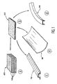
- the elements of reinforcement formed here by the beams 12, the frames 14 and local reinforcements 16, are manufactured separately by draping, consolidation and shaping, from a strip 18 of long fibers impregnated with resin polymerized thermoplastic.
- a tape 18 formed of unidirectional fibers linked together by the polymerized thermoplastic resin usually a strip of woven fibers, also impregnated with polymerized resin can however be used in certain cases.
- the sheet 18 of fibers impregnated with polymerized thermoplastic resin is a flexible, non-adhesive tape, usually stored on a roll.
- the layup step illustrated in a in FIG. 1 can be common to all the reinforcement elements constituted by the healds 12, the frames 14 and the local reinforcements 16, or on the contrary specific to each of these reinforcement elements, depending on whether these elements must have the same thickness or not.
- the strip 18 can also be the same for all the reinforcing elements, or differ for some of them.
- the draping head heats the strip 18 at a temperature above the resin melting temperature, then application pressure on the deposited strip, in order to ensure its diffusion welding on the deposited strip previously.
- the draping head then ensures cooling of the strip immediately after its application, in order to avoid re-peeling.
- means may be provided to ensure a precise positioning of the strips together.
- Blanks 22 are cut from the one or more panels 20, either as these panels are produced, either later. The cuts are made in order to obtain blanks whose dimensions are adapted to those of the reinforcing elements 12, 14 and 16 that we wish to manufacture. These dimensions can also be slightly higher if necessary to perform a clipping after the shaping of reinforcing elements.
- Consolidation of the blanks 22 can be carried out in an autoclave or in a heating press.
- the heddles 12 are straight or substantially straight profiles, which have approximately in section an omega shape.
- Straight profiles of substantially different sections for example in L, Z or U, can be manufactured in the same way, in order to be integrated into the final part.
- the shaping of the reinforcing elements such that the heddles 12 is made by thermoforming, by example in a heating press type machine equipped with a punch and a die, or a punch and a bladder. Formatting techniques by thermoforming of parts in matrix composite material thermoplastics are well known, so that none detailed description will not be given.
- the stages of consolidation and shaping of these reinforcing elements can also be simultaneous.
- the plane blanks 22 cut from the panel 20 are then placed directly in a heating press which simultaneously provides these two functions.
- a heating press similar to that described in document EP-A-0 584 017 can be used.
- the reinforcing elements such as the frames 14 are circular profiles or in an arc.
- these sections have a U-shaped section. Any other section, for example L-shaped, can however be envisaged, without departing from the scope of the invention.
- this blank In order to allow obtaining an element circular from a plane blank 22 initially in form of straight strip, this blank must first be curved in its plan, to ensure the continuity of fibers around the entire circumference of the element.
- This bending can in particular be carried out using a device comparable to that described in the document FR-A-2 635 484, after adaptation of this apparatus for taking into account the thermoplastic character of the resin used.
- This adaptation translates in particular by adding heating means, upstream tapered rollers ensuring the bending of the strip.
- this blank is shaped by thermoforming, either between a punch and a die either between a punch and a bladder, in the same way that the heddles 12 whose shaping has been described previously.
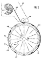
- the tool 23 comprises a hollow mandrel 24, for example metallic, whose outer surface has a shape complementary to that of the lower surface of the skin 10 of the fuselage section that is desired manufacture.
- a mandrel 24 of shape circular has been shown in Figure 2.
- the hollow mandrel 24 is mounted on spokes 26, allowing it to be connected to a central hub 28, by which the mandrel can be driven in rotation in the direction of arrow F in Figure 2.
- This rotational drive can be provided by any suitable means allowing rotation of the mandrel 24 to a constant speed controlled, relatively slow.
- the mandrel 24 On its outer surface, the mandrel 24 has recesses 30 whose shapes are complementary to those of the different elements of reinforcement 12, 14 and 16. Thus, when the beams 12, the frames 14 and the local reinforcements 16 are placed in these recesses 30, all of these reinforcing elements are flush with the outer surface of the mandrel 24 between the recesses 30.
- the assembly of the beams 12 and the frames 14 intertwined is made possible by the fact that notches 14a are formed, for example in frames 14, at the places where these reinforcing elements are cross.
- the notches 14a are formed before placing in place of the beams 12 and of the frames 14 in the recesses 30.
- Maintaining the reinforcing elements in the recesses 30 can be provided by any means suitable such as double-sided adhesive tape, glue dots, or by suction, etc. allowing then easy disassembly.
- the mandrel 24 is itself removable. To this end, it can be made up of several removable sectors assembled together, or adapted to be retracted on itself, or in any other way allowing easy disassembly of the part when it is finished.
- some of the reinforcing elements have turned hollow parts outwards, when these elements are placed in the recesses 30.
- one places in these hollow parts of the cores 40 which avoid any deformation of the skin 10, when the latter is manufactured.
- cores 40 in a material capable of being easily destroyed or disassembled when the part is finished (e.g. soluble nuclei).
- the step process can be started as illustrated Figure 2.
- this step we perform simultaneously manufacturing the skin 10 and the assembly of this skin and the reinforcing elements 12, 14 and 16, by continuous draping and consolidation a strip 32 of long fibers impregnated with resin polymerized thermoplastic, directly on the mandrel 24 carrying these reinforcing elements.
- the strip 32 of long fibers impregnated with resin is generally of the same nature as that which used for the manufacture of the beams 12, the frames 14 and local reinforcements 16. So, this is usually a strip of carbon fibers impregnated with resin PEEK (polyetheretherketone) already polymerized.
- resin PEEK polyetheretherketone
- composite material forming the skin 10 may be different from that in which are made of the reinforcing elements.
- the layup and consolidation operation continuously from a strip 32 initially wound on a reel 34.
- the layup and continuous consolidation are provided by a head drapery illustrated schematically at 36.
- This head draping 36 is mounted on a support (not shown) so as to move gradually parallel to the axis of the mandrel 24.
- the strip 32 is helically wound around the mandrel, according to a sequence of draping defined so as to form gradually the skin 10 of the part.
- Band 32 can also be placed parallel to the axis of the mandrel 24.
- the preheating of the strip 32 is performed at a temperature higher than the temperature resin, in order to make it fluid enough to allow welding by diffusion between the different layers deposited and to facilitate the elimination of porosities.
- a temperature close to 400 ° C can be adopted in the case of a PEEK resin.
- the strip 32 is applied against the mandrel 24, for example by a roller 38, has a pressure generally between 2 and 20 bars, depending on the type of material used.
- Subsequent cooling of the strip filed is intended to avoid re-separation of this bandaged. It aims to bring it down to a temperature lower than the melting temperature of the resin and, if possible, below its transition temperature glass.
- the rotation of the mandrel 24 is stopped and the strip 32 is cut.
- the skin 10 is then already consolidated and welded by diffusion to the elements of reinforcement constituted in this case by the heddles 12, the frames 14 and local reinforcements 16.
- the frame (not shown) which supports the mandrel 24 and the lay-up head 36 can also be used, if necessary, to integrate into the skin of the structure obtained lightning protection and to ensure at least part of the operations of finishing such as depositing a primary coating intended to receive a painting.
- the method according to the invention does not prohibit the subsequent addition of certain reinforcing or other elements made of materials different and especially metallic, when the manufacturing of these elements is not possible or too costly by the manufacturing techniques of composite materials with thermoplastic matrix.
Description
L'invention concerne un procédé permettant de fabriquer des pièces de grandes dimensions, incluant une peau et des éléments de renfort, en un matériau composite à matrice thermoplastique.The invention relates to a method for to manufacture large parts, including a skin and reinforcing elements, of a material composite with thermoplastic matrix.
Le procédé selon l'invention peut être utilisé dans de nombreux secteurs industriels, dès lors que l'on souhaite pouvoir bénéficier des avantages propres aux matériaux composites pour la fabrication de pièces de grandes dimensions comprenant une peau et des éléments de renfort rapportés. Ainsi, dans l'industrie aéronautique, le procédé selon l'invention peut notamment être utilisé pour fabriquer des tronçons de fuselage d'aéronefs, des viroles de nacelles de réacteurs d'avions, etc..The method according to the invention can be used in many industrial sectors, therefore that we want to be able to benefit from the advantages suitable for composite materials for the manufacture of large parts including a skin and reinforcement elements reported. So in the industry aeronautics, the method according to the invention can in particular be used to manufacture sections of fuselage of aircraft, shell of nacelles of aircraft reactors, etc.
Lorsqu'on désire donner à une enveloppe mince, que l'on appellera "peau" dans la suite du texte, une bonne tenue mécanique sans accroítre exagérément sa masse, il est d'usage de lui associer des éléments de renfort tels que des lisses, des cadres, des renforts locaux, etc. rapportés sur la peau.When you want to give to an envelope thin, which will be called "skin" in the rest of the text, good mechanical strength without increasing excessively its mass, it is customary to associate it reinforcing elements such as beams, executives, local reinforcements, etc. reported on the skin.
Dans le passé, de telles structures étaient toujours entièrement métalliques, la peau se présentant sous la forme d'une tôle et les éléments de renfort sous la forme de tôles ou de profilés rapportés sur la peau par des moyens de fixation tels que des rivets. Les structures métalliques ainsi constituées sont encore très nombreuses, notamment lorsque les pièces sont de grandes dimensions. En particulier, dans le domaine aéronautique, les tronçons de fuselage des aéronefs ainsi que les viroles des nacelles entourant les réacteurs des avions sont toujours réalisés de cette manière, comme l'illustrent notamment les documents US-A-5 560 102 et US-A-5 586 381.In the past, such structures were always entirely metallic, the skin presenting itself in the form of a sheet and the reinforcing elements in the form of sheets or profiles attached to the skin by fastening means such as rivets. The metal structures thus formed are still very numerous, especially when the pieces are large. In particular, in the aeronautics, the fuselage sections of aircraft as well as the shrouds of the nacelles surrounding aircraft reactors are always made of this way, as illustrated in particular by documents US-A-5,560,102 and US-A-5,586,381.
Depuis quelques années, une partie de plus en plus importante des pièces métalliques tend à être remplacée par des pièces en matériaux composites formées de fibres longues telles que des fibres de carbone, noyées dans une matrice de résine. Cette évolution s'explique par les avantages propres aux matériaux composites. Ces avantages comprennent notamment un gain de masse d'environ 25 % par rapport à des pièces métalliques comparables, ainsi que des propriétés mécaniques de même niveau que celles des pièces métalliques et susceptibles d'être adaptées à la demande. Les pièces en matériaux composites présentent aussi un bon comportement à la fatigue, une absence de corrosion et d'excellentes propriété spécifiques. Le gain de masse associé aux excellentes propriétés mécaniques des matériaux composites à fibres longues noyées dans une matrice de résine explique en particulier la percée de ces matériaux dans le domaine aéronautique.In recent years, a part more in addition to metal parts tends to be replaced by parts made of composite materials formed from long fibers such as carbon, embedded in a resin matrix. This evolution is explained by the advantages specific to composite materials. These benefits include in particular a weight gain of around 25% compared to comparable metal parts, as well as mechanical properties at the same level as those of metal parts that can be adapted to the request. The composite material parts have also good fatigue behavior, lack of corrosion and excellent specific property. The mass gain associated with excellent properties mechanics of long fiber composites embedded in a resin matrix explains in particularly the breakthrough of these materials in the field aeronautics.
De façon plus précise, la grande majorité des pièces en matériaux composites actuellement utilisées dans l'industrie aéronautique sont des pièces fabriquées à partir d'une résine thermodurcissable. En effet, ce type de résine était initialement le seul qui procurait les propriétés mécaniques recherchées.More specifically, the vast majority parts made of composite materials currently used in the aeronautical industry are parts made from a thermosetting resin. In effect, this type of resin was initially the only one that provided the desired mechanical properties.
La fabrication de pièces en matériaux composites à matrice thermodurcissable a cependant un inconvénient notable. En effet, du fait du caractère thermodurcissable de la résine utilisée, la fabrication de chaque pièce se termine nécessairement par une opération de polymérisation relativement longue, effectuée généralement en autoclave.The manufacture of parts made of materials thermosetting matrix composites however has a notable drawback. Indeed, due to the character thermosetting resin used, manufacturing of each piece necessarily ends with a relatively long polymerization operation, generally performed in an autoclave.
Dans le cas de pièces de petites dimensions, cette dernière opération n'est pas réellement pénalisante. En effet, des autoclaves de petites dimensions relativement peu coûteux peuvent être utilisés et plusieurs pièces peuvent êtres polymérisées simultanément dans chaque autoclave.In the case of small parts dimensions, this last operation is not really penalizing. Indeed, autoclaves of relatively inexpensive small dimensions can be used and several parts can be polymerized simultaneously in each autoclave.
En revanche, lorsque la taille des pièces devient plus importante, une seule pièce à la fois peut être polymérisée dans un même autoclave et l'on doit avoir recours à des autoclaves de très grandes dimensions, particulièrement coûteux. La durée de l'opération et le coût de l'autoclave rendent alors rapidement le procédé mal adapté à une application industrielle. C'est pourquoi, même si les documents US-A-5 170 967 et US-A-5 223 067 envisagent la fabrication d'un tronçon de fuselage d'aéronef en matériau composite à matrice thermodurcissable, la fabrication de pièces de cette taille selon cette technologie reste difficilement justifiable du point de vue industriel.However, when the size of the pieces becomes more important, only one piece at a time can be polymerized in the same autoclave and one must use very large autoclaves dimensions, particularly expensive. The duration of the operation and the cost of the autoclave then make quickly the process ill-suited to an application industrial. This is why, even if the documents US-A-5,170,967 and US-A-5,223,067 envisage the manufacture of an aircraft fuselage section in composite material with thermosetting matrix, manufacturing parts of this size according to this technology is hardly justifiable from the point of industrial view.
Depuis l'apparition relativement récente de résines thermoplastiques telles que la résine PEEK (Polyétheréthercétone), permettant d'obtenir des matériaux composites à fibres longues et à matrice thermoplastique présentant des caractéristiques mécaniques équivalentes à celles des matériaux composites à matrice thermodurcissable les plus récents, on tend également à remplacer les pièces métalliques existantes par des pièces en matériau composite à matrice thermoplastique.Since the relatively recent appearance of thermoplastic resins such as PEEK resin (Polyetheretherketone), allowing to obtain long fiber and matrix composite materials thermoplastic with characteristics mechanical equivalent to that of materials most thermosetting matrix composites recent, we also tend to replace parts existing metal by pieces of material composite with thermoplastic matrix.
Ces matériaux composites à matrice thermoplastique présentent, outre les avantages des matériaux composites à matrice organique cités précédemment, une bonne tenue à l'impact et au feu ainsi qu'une faible reprise d'humidité. Enfin, les demi-produits se conservent à température ambiante et ont une durée de vie pratiquement illimitée, du fait que la résine qui imprègne les fils est déjà polymérisée.These matrix composite materials thermoplastic have, in addition to the advantages of organic matrix composite materials mentioned previously, good resistance to impact and fire as well as a low moisture uptake. Finally, the semi-finished products keep at room temperature and have an almost unlimited lifespan, because that the resin that permeates the threads is already polymerized.
Comme l'illustre notamment le document US-A- 5 362 347, on a déjà proposé de fabriquer le bord d'attaque d'une aile d'avion en matériau composite à matrice thermoplastique. Plus précisément, ce document envisage de fabriquer séparément les éléments de renfort et la peau, puis de les assembler par soudage/diffusion.As illustrated in particular by the document US-A- 5,362,347, it has already been proposed to manufacture the edge of an airplane wing made of composite material thermoplastic matrix. More specifically, this document plans to manufacture the components of reinforcement and skin, then assemble them by welding / diffusion.
Du fait que les éléments de renfort et la peau sont fabriqués séparément avant d'être assemblés, la peau comme les éléments de renfort doivent subir des opérations de consolidation avant leur assemblage. Il est rappelé que ces opérations de consolidation ont principalement pour fonction la création de la liaison entre les différentes couches constituant, d'une part, la peau et, d'autre part, chacun des éléments de renfort, tout en éliminant les porosités. Elles consistent en l'application d'une pression sur l'élément à consolider, et son chauffage à une température déterminée, supérieure à la température de fusion de la résine. Ces opérations de consolidation s'effectuent en autoclave. Cela rend ce procédé mal adapté à la fabrication de pièces présentant une peau de grandes dimensions, pour des raisons identiques à celles qui ont été mentionnées dans le cadre de la fabrication de pièces en matériau composite à matrice thermodurcissable.Because the reinforcing elements and the skin are manufactured separately before being assembled, the skin and the reinforcing elements must undergo consolidation operations before their assembly. he it is recalled that these consolidation operations have mainly for function the creation of the connection between the different layers constituting, on the one hand, the skin and, on the other hand, each of the elements of reinforcement, while eliminating porosity. They consist of applying pressure to the element to consolidate, and its heating to a temperature determined, higher than the melting temperature resin. These consolidation operations are carried out in an autoclave. This makes this process ill-suited to the manufacture of parts with large skin dimensions, for reasons identical to those which have been mentioned in connection with the manufacture of parts made of composite material with thermosetting matrix.
L'invention a précisément pour objet un procédé permettant de fabriquer des pièces de grandes dimensions, telles que des tronçons de fuselage d'aéronefs, en un matériau composite à matrice thermoplastique, d'une manière particulièrement rapide et peu coûteuse, adaptée à une fabrication industrielle à cadence relativement élevée, sans réelle limitation de taille du fait que ni la peau, ni la structure finale obtenue ne doivent passer en autoclave à la fin de leur fabrication.The subject of the invention is precisely a process for making large parts dimensions, such as sections of aircraft fuselage, in a composite material with a thermoplastic matrix, particularly quickly and little expensive, suitable for industrial manufacturing at relatively high speed, with no real limitation of size because neither the skin nor the final structure obtained should only be autoclaved at the end of their manufacturing.
Conformément à l'invention, ce résultat est obtenu au moyen d'un procédé de fabrication de pièces en matériau composite, incluant une peau et des éléments de renfort, ce procédé comprenant les étapes suivantes :
- fabrication séparée des éléments de renfort, par drapage, consolidation et mise en forme, à partir d'une bande de fibres longues imprégnées de résine thermoplastique ;
- mise en place des éléments de renfort sur un outillage de forme complémentaire de la pièce à fabriquer ;
- separate manufacture of the reinforcement elements, by draping, consolidation and shaping, from a strip of long fibers impregnated with thermoplastic resin;
- placing reinforcing elements on a tool of complementary shape to the part to be manufactured;
Du fait que les éléments de renfort et la peau sont assemblés lors de la fabrication de celle-ci et du fait que cette fabrication inclut la consolidation en continu d'une bande de fibres formant la peau, lors de son drapage, des pièces de dimensions quelconques peuvent être fabriquées, sans qu'il soit nécessaire de placer la peau ou la pièce obtenue dans un autoclave.Because the reinforcing elements and the skin are assembled during the manufacture of this and the fact that this manufacturing includes consolidation in continuous band of fibers forming the skin, during its draping, pieces of any size can be manufactured without the need to place the skin or the piece obtained in an autoclave.
Par ailleurs, le temps de fabrication des pièces est particulièrement court puisque l'assemblage de la peau et des éléments de renfort et la fabrication de la peau sont simultanés. En outre, les éléments de renfort d'une pièce donnée peuvent être fabriqués lorsque la peau de la pièce précédente est elle-même en cours de fabrication.Furthermore, the manufacturing time of the parts is particularly short since the assembly of skin and reinforcing elements and making the skin are simultaneous. In addition, the reinforcing elements of a given part can be manufactured when the skin of the previous piece is itself in progress Manufacturing.
Dans une forme de réalisation préférée de l'invention, les éléments de renfort sont fabriqués par dépose automatisée en continu d'une bande de fibres longues imprégnées de résine thermoplastique polymérisée, de façon à former un panneau, comparable à une tôle dans une pièce métallique classique, par découpe de flans dans ce panneau, puis par consolidation et mise en forme de ces flans. In a preferred embodiment of the invention, the reinforcing elements are manufactured by continuous automated removal of a strip of fibers long impregnated with polymerized thermoplastic resin, so as to form a panel, comparable to a sheet metal in a classic metal part, by cutting blanks in this panel, then by consolidation and shaping of these blanks.
Généralement les flans sont consolidés avant d'être mis en forme.Generally the blanks are consolidated before being shaped.
La consolidation des flans peut se faire soit en autoclave, soit sous presse chauffante. Il est à noter que la consolidation en autoclave ou sous presse chauffante concerne alors des pièces de relativement petites dimensions, de sorte qu'un autoclave ou une presse chauffante ordinaires, de dimensions conventionnelles peuvent être utilisés et que plusieurs flans peuvent y être consolidés simultanément.Consolidation of the blanks can be done either in an autoclave or in a heating press. It is note that consolidation in an autoclave or under heating press then concerns parts of relatively small dimensions, so that a autoclave or ordinary heating press, conventional dimensions can be used and that several blanks can be consolidated there simultaneously.
Par ailleurs, les flans sont de préférence mis en forme par thermoformage. Si une bonne orientation des fibres dans l'élément de renfort le nécessite, le thermoformage peut être précédé d'une opération de cintrage.Furthermore, the blanks are preferably shaped by thermoforming. If a good orientation of the fibers in the reinforcing element the requires, thermoforming can be preceded by bending operation.
Dans certains cas particuliers, et notamment lorsque les éléments de renfort présentent une courbure relativement limitée par rapport à un plan, les flans peuvent être consolidés et mis en forme simultanément par thermoformage dans une presse chauffante.In certain special cases, and especially when the reinforcing elements have a relatively limited curvature compared to a plan, the blanks can be consolidated and shaped simultaneously by thermoforming in a press heating.
Le procédé selon l'invention est avantageusement appliqué à la fabrication d'une pièce creuse. On place alors les éléments de renfort dans des évidements prévus sur un mandrin appartenant à l'outillage, puis on drape et on consolide en continu la bande sur ce mandrin en le faisant tourner autour de son axe.The method according to the invention is advantageously applied to the manufacture of a part dig. The reinforcing elements are then placed in recesses provided on a mandrel belonging to the tools, then we drape and consolidate continuously the strip on this mandrel by rotating it around its axis.
Dans le cas particulier où le procédé selon l'invention est appliqué à la fabrication de tronçons de fuselage d'aéronefs, on fabrique des éléments de renfort comprenant des lisses, des cadres et des renforts locaux.In the particular case where the method according to the invention is applied to the manufacture of sections of aircraft fuselage, we manufacture elements of reinforcement comprising beams, frames and local reinforcements.
On décrira à présent, à titre d'exemple non limitatif, une forme préférée de mise en oeuvre de l'invention en se référant aux dessins annexés, dans lesquels :
- la figure 1 illustre de façon schématique une première étape du procédé selon l'invention, au cours de laquelle des lisses, des renforts locaux et des cadres sont fabriqués séparément ;
- la figure 2 est une vue en coupe transversale qui représente schématiquement l'étape ultime du procédé selon l'invention, au cours de laquelle on effectue simultanément la fabrication de la peau et son assemblage aux éléments de renfort ; et
- la figure 3 est une vue en perspective illustrant l'agencement relatif des lisses et des cadres dans le tronçon de fuselage que l'on désire fabriquer.
- Figure 1 schematically illustrates a first step of the method according to the invention, during which beams, local reinforcements and frames are produced separately;
- Figure 2 is a cross-sectional view which schematically represents the final step of the method according to the invention, during which the skin is simultaneously made and assembled with the reinforcing elements; and
- Figure 3 is a perspective view illustrating the relative arrangement of beams and frames in the fuselage section that one wishes to manufacture.
Le procédé conforme à l'invention va à
présent être décrit dans son application à la
fabrication d'un tronçon de fuselage d'aéronef. Comme
le montrent notamment les figures 2 et 3, un tel
tronçon de fuselage comprend une peau extérieure 10,
ainsi que des éléments de renfort constitués par des
lisses 12, des cadres 14 et des renforts locaux 16. Les
lisses 12 et les cadres 14, orientés respectivement
selon des directions longitudinales et
circonférentielles, constituent l'ossature du fuselage
(figure 3), de la même manière que lorsque celui-ci est
métallique. Les renforts locaux 16 forment des
surépaisseurs qui viennent s'ajouter localement à la
peau 10 afin de la renforcer, notamment dans les
régions où se trouvent les hublots 17 (figure 3).The process according to the invention goes to
present be described in its application to the
manufacture of an aircraft fuselage section. As
shown in particular in Figures 2 and 3, such
fuselage section comprises an
Cette application ne doit cependant pas être considérée comme limitative. En effet, comme on l'a déjà observé, le procédé selon l'invention peut être utilisé pour fabriquer toutes pièces de grandes dimensions en matériau composite à matrice thermoplastique, formées par l'assemblage d'une peau et d'éléments de renfort. Par conséquent, la forme et les dimensions de la pièce peuvent être différentes, de même que la nature, le nombre et l'agencement des éléments de renfort. En particulier, si l'invention est particulièrement adaptée à la fabrication d'une pièce creuse de révolution, elle peut aussi s'appliquer à la fabrication de pièces de formes différentes, non de révolution.This application should not however be considered limiting. Indeed, as we already observed, the process according to the invention can be used to fabricate large parts dimensions in matrix composite material thermoplastic, formed by the assembly of a skin and reinforcing elements. Therefore, the shape and room dimensions may be different, from as well as the nature, number and arrangement of reinforcing elements. In particular, if the invention is particularly suitable for the production of a part hollow of revolution, it can also be applied to the manufacture of parts of different shapes, not of revolution.
Selon une première étape du procédé de
fabrication conforme à l'invention, les éléments de
renfort constitués ici par les lisses 12, les cadres 14
et les renforts locaux 16, sont fabriqués séparément
par drapage, consolidation et mise en forme, à partir
d'une bande 18 de fibres longues imprégnées de résine
thermoplastique polymérisée.According to a first step in the
manufacturing according to the invention, the elements of
reinforcement formed here by the
Dans la pratique, on utilise généralement des fibres de carbone imprégnées de résine PEEK (polyétheréthercétone). Des fibres et/ou une résine thermoplastique de natures différentes peuvent toutefois être utilisées dans certaines applications, sans sortir du cadre de l'invention.In practice, we generally use carbon fibers impregnated with PEEK resin (Polyetheretherketone). Fibers and / or resin thermoplastics of different natures can however be used in some applications, without departing from the scope of the invention.
On utilise généralement une bande 18
formées de fibres unidirectionnelles liées entre elles
par la résine thermoplastique polymérisée. En variante,
une bande de fibres tissées, également imprégnées de
résine polymérisée peut toutefois être utilisée dans
certains cas. A température ambiante, la nappe 18 de
fibres imprégnées de résine thermoplastique polymérisée
est une bande souple et non adhésive, habituellement
stockée sur un rouleau.Usually a
L'étape de drapage de la bande 18,
illustrée schématiquement en a sur la figure 1,
consiste à déposer la bande 18 sur plusieurs
épaisseurs, pour former un certain nombre de couches ou
de plis, selon des orientations qui peuvent ou non
varier d'un pli à l'autre, pour tenir compte des
caractéristiques mécaniques que l'on désire obtenir. Le
nombre de plis superposés au cours de cette étape de
drapage dépend également des caractéristiques
mécaniques souhaitées pour les éléments de renfort
12, 14 et 16.The step of draping the
L'étape de drapage illustrée en a sur la
figure 1 peut être commune à tous les éléments de
renfort constitués par les lisses 12 les cadres 14 et
les renforts locaux 16, ou au contraire spécifique à
chacun de ces éléments de renfort, selon que ces
éléments doivent présenter ou non la même épaisseur. La
bande 18 peut également être la même pour tous les
éléments de renfort, ou différer pour certains d'entre
eux.The layup step illustrated in a in FIG. 1 can be common to all the reinforcement elements constituted by the
Selon le cas, on fabrique ainsi par drapage
un ou plusieurs types de panneaux plans 20. Depending on the case, we manufacture by draping
one or more types of
L'opération de drapage de la bande 18, à
partir du rouleau (non représenté) sur lequel le
matériau est bobiné, est de préférence assurée par une
tête de drapage (non représentée) adaptée au drapage
d'une bande formée de fibres longues imprégnées de
résine thermoplastique polymérisée. A cet effet, on
utilisera avantageusement la tête de drapage à grande
vitesse décrite dans la demande de brevet français n°
96 14799.The draping operation of the
La tête de drapage assure le chauffage de
la bande 18 à une température supérieure à la
température de fusion de la résine, puis l'application
d'une pression sur la bande déposée, afin d'assurer son
soudage par diffusion sur la bande déposée
précédemment. La tête de drapage assure ensuite le
refroidissement de la bande immédiatement après son
application, afin d'éviter son redécollement. En outre,
des moyens peuvent être prévus pour assurer un
positionnement précis des bandes entre elles.The draping head heats
the
La bande 18 est déposée par la tête de
drapage sur un support plan, généralement fixe. Le ou
les panneaux 20 obtenus par cette opération de drapage
sont donc des panneaux plans, de préférence de grandes
dimensions, qui peuvent être fabriqués en continu dans
le cadre d'un procédé industriel.The
Des flans 22 sont découpés dans le ou les
panneaux 20, soit au fur et à mesure que ces panneaux
sont fabriqués, soit ultérieurement. Les découpes sont
faites afin d'obtenir des flans dont les dimensions
sont adaptées à celles des éléments de renfort 12, 14
et 16 que l'on désire fabriquer. Ces dimensions peuvent
aussi être légèrement supérieures s'il est nécessaire
d'effectuer un détourage après la mise en forme des
éléments de renfort.
Comme on l'a illustré schématiquement en b
sur la figure 1, les flans 22 découpés dans le ou les
panneaux 20 subissent généralement ensuite une
opération de consolidation qui a principalement pour
fonctions d'éliminer les porosités à l'intérieur du
matériau et d'améliorer la liaison entre les
différentes couches qui le constituent.As illustrated schematically in b in FIG. 1, the
Cette opération de consolidation se caractérise par l'application d'une pression sur les flans 22 (généralement comprise entre 2 à 20 bars, selon le type de matériau utilisé), et par leur chauffage à une température généralement supérieure à la température de fusion de la résine, afin d'assurer son ramollissement (par exemple, à environ 400°C dans le cas d'une résine PEEK).This consolidation operation is characterized by the application of pressure on the blanks 22 (generally between 2 to 20 bars, depending on the type of material used), and by their heating to a temperature generally higher than the melting temperature of the resin, to ensure softening (for example, around 400 ° C in PEEK resin).
La consolidation des flans 22 peut être
effectuée en autoclave ou dans une presse chauffante.Consolidation of the
Lorsque la consolidation est effectuée en
autoclave, il est à noter que les autoclaves utilisés
sont des autoclaves classiques, de dimensions
conventionnelles, puisque les dimensions des flans 22 à
consolider correspondent aux dimensions des éléments de
renfort de la pièce à fabriquer, avant que ces éléments
soient mis en forme. Généralement, plusieurs flans 22
peuvent être consolidés dans un même autoclave, ce qui
procure un gain de temps et une économie notables.When consolidation is carried out in
autoclave, it should be noted that the autoclaves used
are classic autoclaves, of dimensions
conventional, since the dimensions of the
En variante, la consolidation des flans 22
peut aussi être faite dans une presse chauffante telle
que celle qui est décrite dans le document
EP-A-0 584 017. As a variant, the consolidation of the
Les différents flans 22 consolidés sont
ensuite mis en forme séparément, comme on l'a illustré
schématiquement en c, d et e respectivement pour les
lisses 12, les cadres 14 et les renforts locaux 16.The various
Comme on l'a illustré schématiquement en c
sur la figure 1, les lisses 12 sont des profilés
rectilignes ou sensiblement rectilignes, qui présentent
approximativement en section une forme en oméga. Des
profilés rectilignes de sections sensiblement
différentes, par exemple en L, Z ou U, peuvent être
fabriqués de la même manière, en vue d'être intégrés
dans la pièce finale.As illustrated schematically in c in Figure 1, the
La mise en forme des éléments de renfort
tels que les lisses 12 est faite par thermoformage, par
exemple dans une machine de type presse chauffante
équipée d'un poinçon et d'une matrice, ou d'un poinçon
et d'une vessie. Les techniques de mise en forme par
thermoformage de pièces en matériau composite à matrice
thermoplastique sont bien connues, de sorte qu'aucune
description détaillée n'en sera faite.The shaping of the reinforcing elements
such that the
Comme on l'a illustré schématiquement en d
sur la figure 1, les éléments de renfort tels que les
renforts locaux 16, constitués par des tronçons de
panneaux légèrement incurvés par rapport à un plan,
peuvent être également fabriqués par thermoformage,
notamment entre un poinçon et une vessie, à partir de
flans plans 22 précédemment consolidés. La mise en
forme peut notamment être faite dans une presse
chauffante analogue à celle qui est décrite dans le
document EP-A-0 584 017, déjà cité.As illustrated schematically in d in FIG. 1, the reinforcing elements such as the
Compte tenu de la faible courbure des
renforts locaux 16, les étapes de consolidation et de
mise en forme de ces éléments de renfort peuvent aussi
être simultanées. Les flans plans 22 découpés dans le
panneau 20 sont alors placés directement dans une
presse chauffante qui assure simultanément ces deux
fonctions. Là encore, une presse chauffante analogue à
celle qui est décrite dans le document EP-A-0 584 017
peut être utilisée.Given the small curvature of the
Comme on l'a illustré schématiquement en e
sur la figure 1, les éléments de renfort tels que les
cadres 14 sont des profilés circulaires ou en arc de
cercle. Dans la forme de réalisation représentée, ces
profilés présentent une section en U. Toute autre
section, par exemple en forme de L, peut toutefois être
envisagée, sans sortir du cadre de l'invention.As illustrated schematically at e in Figure 1, the reinforcing elements such as the
Afin de permettre l'obtention d'un élément
circulaire à partir d'un flan plan 22 initialement en
forme de bande droite, ce flan doit tout d'abord être
cintré dans son plan, pour assurer la continuité des
fibres sur toute la circonférence de l'élément. Ce
cintrage peut notamment être effectué à l'aide d'un
appareil comparable à celui qui est décrit dans le
document FR-A-2 635 484, après adaptation de cet
appareil pour tenir compte du caractère thermoplastique
de la résine utilisée. Cette adaptation se traduit
notamment par l'ajout de moyens de chauffage, en amont
des rouleaux coniques assurant le cintrage de la bande.In order to allow obtaining an element
circular from a
Lorsque le flan 22 en forme de bande a été
cintré dans son plan, ce flan est mis en forme par
thermoformage, soit entre un poinçon et une matrice
soit entre un poinçon et une vessie, de la même manière
que les lisses 12 dont la mise en forme a été décrite
précédemment.When the strip-shaped blank 22 has been
bent in its plane, this blank is shaped by
thermoforming, either between a punch and a die
either between a punch and a bladder, in the same way
that the
Il est important d'observer que les
différentes opérations de drapage, consolidation et
mise en forme, constituant la première étape de
fabrication des éléments de renfort 12, 14 et 16 qui
vient d'être décrite, peuvent être réalisées
simultanément dans le cadre d'un processus de
fabrication en série des tronçons de fuselage.It is important to note that
different draping, consolidation and
shaping, constituting the first stage of
manufacture of the reinforcing
Lorsque les lisses 12, les renforts locaux
16 et les cadres 14 nécessaires à la fabrication d'un
tronçon de fuselage sont disponibles, tous ces éléments
de renfort sont mis en place sur un outillage 23, comme
on l'a illustré schématiquement sur la figure 2.When the
De façon plus précise, l'outillage 23
comprend un mandrin creux 24, par exemple métallique,
dont la surface extérieure présente une forme
complémentaire de celle de la surface inférieure de la
peau 10 du tronçon de fuselage que l'on désire
fabriquer. Pour simplifier, un mandrin 24 de forme
circulaire a été représenté sur la figure 2.More precisely, the
Comme on l'a illustré de façon très
schématique, le mandrin creux 24 est monté sur des
rayons 26, permettant de le relier à un moyeu central
28, par lequel le mandrin peut être entraíné en
rotation dans le sens de la flèche F sur la figure 2.
Cet entraínement en rotation peut être assuré par tout
moyen approprié permettant une rotation du mandrin 24 à
une vitesse constante contrôlée, relativement lente.As we very clearly illustrated
schematically, the
Sur sa surface extérieure, le mandrin 24
comporte des évidements 30 dont les formes sont
complémentaires de celles des différents éléments de
renfort 12, 14 et 16. Ainsi, lorsque les lisses 12, les
cadres 14 et les renforts locaux 16 sont placés dans
ces évidements 30, tous ces éléments de renfort
affleurent la surface extérieure du mandrin 24 entre
les évidements 30. On its outer surface, the
Comme l'illustre schématiquement la figure
3, le montage des lisses 12 et des cadres 14
entrecroisés est rendu possible par le fait que des
entailles 14a sont formées, par exemple dans les cadres
14, aux endroits où ces éléments de renfort se
croisent. Les entailles 14a sont formées avant la mise
en place des lisses 12 et des cadres 14 dans les
évidements 30.As schematically illustrated in the figure
3, the assembly of the
Le maintien des éléments de renfort dans
les évidements 30 peut être assuré par tout moyen
approprié tel qu'un ruban adhésif double face, des
points de colle, ou par aspiration, etc. permettant
ensuite un démontage aisé. Pour permettre ce démontage,
le mandrin 24 est lui-même démontable. A cet effet, il
peut être formé de plusieurs secteurs démontables
assemblés entre eux, ou apte à être rétracté sur
lui-même, ou encore de toute autre manière permettant
un démontage aisé de la pièce lorsqu'elle est terminée.Maintaining the reinforcing elements in
the
Comme on l'a représenté sur la figure 2,
certains des éléments de renfort (dans ce cas, les
lisses 12) présentent des parties en creux tournées
vers l'extérieur, lorsque ces éléments sont placés dans
les évidements 30. De préférence, on place dans ces
parties en creux des noyaux 40 qui évitent toute
déformation de la peau 10, lorsque celle-ci est
fabriquée. Selon des techniques analogues à celles qui
sont utilisées pour le moulage, on utilise des noyaux
40 en un matériau apte à être aisément détruit ou
démonté lorsque la pièce est terminée (par exemple des
noyaux solubles).As shown in Figure 2,
some of the reinforcing elements (in this case, the
smooth 12) have turned hollow parts
outwards, when these elements are placed in
the
Lorsque tous les éléments de renfort
entrant dans la composition d'un tronçon de fuselage
ont été mis en place dans les évidements 30, l'étape
suivante du procédé peut être entamée comme l'illustre
la figure 2. Au cours de cette étape, on effectue
simultanément la fabrication de la peau 10 et
l'assemblage de cette peau et des éléments de renfort
12, 14 et 16, par drapage et consolidation en continu
d'une bande 32 de fibres longues imprégnées de résine
thermoplastique polymérisée, directement sur le mandrin
24 portant ces éléments de renfort.When all the reinforcing elements
used in the composition of a fuselage section
have been placed in the
La bande 32 de fibres longues imprégnées de
résine est généralement de même nature que celle qui a
servi à la fabrication des lisses 12, des cadres 14 et
des renforts locaux 16. Ainsi, il s'agit généralement
d'une bande de fibres de carbone imprégnées de résine
PEEK (polyétheréthercétone) déjà polymérisée.
Toutefois, il est à noter que dans certaines
applications particulières, le matériau composite
formant la peau 10 peut être différent de celui dans
lequel sont réalisés les éléments de renfort.The strip 32 of long fibers impregnated with
resin is generally of the same nature as that which
used for the manufacture of the
Comme on l'a illustré schématiquement sur
la figure 2, l'opération de drapage et de consolidation
en continu s'effectue à partir d'une bande 32
initialement enroulée sur une bobine 34. Le drapage et
la consolidation en continu sont assurés par une tête
de drapage illustrée schématiquement en 36. Cette tête
de drapage 36 est montée sur un support (non
représenté) de façon à se déplacer progressivement
parallèlement à l'axe du mandrin 24. Lorsque celui-ci
est entraíné en rotation dans le sens de la flèche F,
la bande 32 est enroulée en hélice autour du mandrin,
selon une séquence du drapage définie de façon à former
progressivement la peau 10 de la pièce. La bande 32
peut également être déposée parallèlement à l'axe du
mandrin 24. As schematically illustrated on
Figure 2, the layup and consolidation operation
continuously from a strip 32
initially wound on a
Il est à noter que tout autre mouvement
relatif entre la tête de drapage 36 et le mandrin 24
permettant de former la peau 10 pourrait être utilisé,
sans sortir du cadre de l'invention.It should be noted that any other movement
relative between the lay-up
La tête de drapage 36 est conçue pour
réaliser simultanément le drapage de la bande 32 sur la
mandrin 24, la consolidation en continu de la peau 10
ainsi fabriquée, et l'assemblage de cette peau 10 et
des éléments de renfort constitués par les lisses 12,
les cadres 14 et les renforts locaux 16. A cet effet,
la tête de drapage 36 soumet le matériau à un cycle de
pression et de température prédéterminé. Ce cycle
comprend le chauffage de la bande 32 immédiatement
avant son application sur le mandrin 24, l'application
d'une pression sur la bande 32 lorsqu'elle est
appliquée sur le mandrin, puis le refroidissement de la
bande qui vient être déposée.The lay-up
Le chauffage préalable de la bande 32 est effectué à une température supérieure à la température de fusion de la résine, afin de rendre celle-ci suffisamment fluide pour permettre le soudage par diffusion entre les différentes couches déposées et pour faciliter l'élimination des porosités. A titre d'illustration nullement limitative, une température voisine de 400°C peut être adoptée dans le cas d'une résine PEEK.The preheating of the strip 32 is performed at a temperature higher than the temperature resin, in order to make it fluid enough to allow welding by diffusion between the different layers deposited and to facilitate the elimination of porosities. As nonlimiting illustration, a temperature close to 400 ° C can be adopted in the case of a PEEK resin.
La bande 32 est appliquée contre le mandrin
24, par exemple par un rouleau 38, a une pression
généralement comprise entre 2 et 20 bars, selon le type
de matériau utilisé.The strip 32 is applied against the
Le refroidissement ultérieur de la bande déposée est destiné à éviter le redécollement de cette bande. Il vise à ramener celle-ci a une température inférieure à la température de fusion de la résine et, si possible, inférieure à sa température de transition vitreuse.Subsequent cooling of the strip filed is intended to avoid re-separation of this bandaged. It aims to bring it down to a temperature lower than the melting temperature of the resin and, if possible, below its transition temperature glass.
Lorsque le nombre de couches désiré pour la
peau 10 est obtenu, la rotation du mandrin 24 est
stoppée et la bande 32 est coupée. La peau 10 est alors
déjà consolidée et soudée par diffusion aux éléments de
renfort constitués dans ce cas par les lisses 12, les
cadres 14 et les renforts locaux 16.When the number of layers desired for the
Par conséquent, le tronçon de fuselage est
obtenu immédiatement, après démontage ou rétraction du
mandrin 24 et enlèvement des noyaux 40 placés à
l'intérieur des lisses 12. En particulier, le tronçon
de fuselage ainsi obtenu ne nécessite pas de passage
ultérieur en autoclave.Therefore, the fuselage section is
obtained immediately, after disassembly or retraction of the
Dans une extension du procédé selon
l'invention, le bâti (non représenté) qui supporte le
mandrin 24 et la tête de drapage 36 peut également être
utilisé, si nécessaire, pour intégrer à la peau de la
structure obtenue une protection contre la foudre et
pour assurer au moins en partie des opérations de
finition telles que le dépôt d'un revêtement primaire
destiné à recevoir une peinture.In an extension of the process according to
the invention, the frame (not shown) which supports the
La description qui précède fait apparaítre que le procédé selon l'invention permet de fabriquer, de manière industrielle et à moindre coût, des pièces en matériau composite à matrice thermoplastique de grandes dimensions, formées par l'assemblage d'une peau et d'éléments de renfort, pratiquement sans limitation de taille. Un grand nombre de pièces habituellement métalliques peuvent ainsi être fabriquées en matériau composite, ce qui permet de bénéficier des avantages propres à ces matériaux. The foregoing description makes it appear that the process according to the invention makes it possible to manufacture, industrially and at low cost, parts made of composite material with a thermoplastic matrix of large dimensions, formed by the assembly of a skin and reinforcing elements, practically without limitation of size. A large number of pieces usually metal can thus be made of material composite, which allows to benefit from the advantages specific to these materials.
Il est à noter que le procédé selon l'invention n'interdit pas l'ajout ultérieur de certains éléments de renfort ou autres en matériaux différents et notamment métalliques, lorsque la fabrication de ces éléments n'est pas possible ou trop coûteuse par les techniques de fabrication des matériaux composites à matrice thermoplastique.It should be noted that the method according to the invention does not prohibit the subsequent addition of certain reinforcing or other elements made of materials different and especially metallic, when the manufacturing of these elements is not possible or too costly by the manufacturing techniques of composite materials with thermoplastic matrix.
Claims (10)
- Fabrication process for parts with large dimensions, from a composite material comprising a skin (10) and stiffeners (12, 14, 16), said process comprising the following steps:characterized in that it also comprises the fabrication of the skin (10) and simultaneous assembly of the skin and the stiffeners (12, 14, 16), by lay-up and continuous consolidation of at least one strip (32) of long fibers impregnated with thermoplastic resin, directly on the tooling (23) on which the stiffeners (12, 14, 16) are placed, followed by the cooling of the deposited strip to a temperature below the melting point of the resin.separate fabrication of stiffeners (12, 14, 16) by lay-up, consolidation and shaping, starting from a strip (18) of long fibers impregnated with thermoplastic resin;placement of stiffeners (12, 14, 16) on a tooling (23) with a shape complementary to the shape of the part to be fabricated; and
- Process according to claim 1, in which the stiffeners (12, 14, 16) are made by continuously and automatically depositing a strip (18) of long fibers impregnated with polymerized thermoplastic resin in order to form a panel (29), by cutting blanks (22) out of this panel, and then by consolidation and shaping of these blanks (22).
- Process according to claim 2, in which the blanks (22) are consolidated before they are shaped.
- Process according to either of claims 2 or 3, in which the blanks (22) are consolidated in an autoclave or in a heating press.
- Process according to any one of claims 2 to 4, in which the blanks (22) are shaped by thermoforming.
- Process according to claim 5, in which the blanks (22) are bent before they are shaped by thermoforming.
- Process according to claim 2, in which the blanks (22) are consolidated and shaped simultaneously by thermoforming, in a heating press.
- Process according to any one of the previous claims applied to the fabrication of a hollow part, in which the stiffeners (12, 14, 16) are placed in recesses formed on a mandrel (23) forming part of the tooling (24), and in which the lay-up is then done and the strip (32) is continuously consolidated on this mandrel by rotating the mandrel around its axis.
- Process according to claim 8, applied to the fabrication of aircraft fuselage segments, in which stiffeners comprising rails (12), frames (14) and local stiffeners (16) are fabricated.
- Process according to any one of the previous claims, in which lightning protection is then integrated into the skin (10).
Applications Claiming Priority (3)
| Application Number | Priority Date | Filing Date | Title |
|---|---|---|---|
| FR9709265 | 1997-07-22 | ||
| FR9709265A FR2766407B1 (en) | 1997-07-22 | 1997-07-22 | PROCESS FOR MANUFACTURING LARGE-DIMENSIONAL PARTS IN COMPOSITE MATERIAL WITH A THERMOPLASTIC MATRIX, SUCH AS FUSELAGE TRUNKS OF AIRCRAFT |
| PCT/FR1998/001584 WO1999004952A1 (en) | 1997-07-22 | 1998-07-20 | Method for making parts in composite material with thermoplastic matrix |
Publications (2)
| Publication Number | Publication Date |
|---|---|
| EP0998383A1 EP0998383A1 (en) | 2000-05-10 |
| EP0998383B1 true EP0998383B1 (en) | 2002-11-13 |
Family
ID=9509457
Family Applications (1)
| Application Number | Title | Priority Date | Filing Date |
|---|---|---|---|
| EP98939716A Expired - Lifetime EP0998383B1 (en) | 1997-07-22 | 1998-07-20 | Method for making parts in composite material with thermoplastic matrix |
Country Status (9)
| Country | Link |
|---|---|
| US (1) | US6613258B1 (en) |
| EP (1) | EP0998383B1 (en) |
| JP (1) | JP2001510746A (en) |
| CN (1) | CN1077842C (en) |
| CA (1) | CA2297266C (en) |
| DE (1) | DE69809427T2 (en) |
| ES (1) | ES2186202T3 (en) |
| FR (1) | FR2766407B1 (en) |
| WO (1) | WO1999004952A1 (en) |
Cited By (6)
| Publication number | Priority date | Publication date | Assignee | Title |
|---|---|---|---|---|
| US7678317B2 (en) | 1999-10-08 | 2010-03-16 | Anthony Khouri | Concrete mixing drum manufacturing method |
| US7744267B2 (en) | 2003-08-15 | 2010-06-29 | Mcneilus Truck And Manufacturing, Inc. | Mixing drum drive ring |
| US7784995B2 (en) | 2002-05-31 | 2010-08-31 | Anthony Khouri | Vehicle mounted concrete mixing drum and method of manufacture thereof |
| US7802914B2 (en) | 2003-08-15 | 2010-09-28 | McNeihus Truck and Manufacturing, Inc. | Mixing drum blade support |
| US8162529B2 (en) | 2004-03-04 | 2012-04-24 | Mcneilus Truck And Manufacturing, Inc. | Mixing drum |
| US8287173B2 (en) | 2003-08-15 | 2012-10-16 | Mcneilus Truck And Manufacturing, Inc. | Mixing drum hatch |
Families Citing this family (107)
| Publication number | Priority date | Publication date | Assignee | Title |
|---|---|---|---|---|
| US6889937B2 (en) | 1999-11-18 | 2005-05-10 | Rocky Mountain Composites, Inc. | Single piece co-cure composite wing |
| US7681835B2 (en) | 1999-11-18 | 2010-03-23 | Rocky Mountain Composites, Inc. | Single piece co-cure composite wing |
| AU2002216657A1 (en) * | 2000-11-15 | 2002-05-27 | Toyota Motor Sales, U.S.A., Inc. | One-piece closed-shape structure and method of forming same |
| US7204951B2 (en) | 2002-07-30 | 2007-04-17 | Rocky Mountain Composites, Inc. | Method of assembling a single piece co-cured structure |
| US6729576B2 (en) * | 2002-08-13 | 2004-05-04 | Sikorsky Aircraft Corporation | Composite tail cone assembly |
| US7282107B2 (en) * | 2003-08-22 | 2007-10-16 | The Boeing Company | Multiple head automated composite laminating machine for the fabrication of large barrel section components |
| ES2263324B1 (en) * | 2004-03-18 | 2007-11-01 | Manuel Torres Martinez | PROCEDURE FOR THE MANUFACTURE OF AIRCRAFT FUSELAGES AND DEVICE TO CARRY OUT THIS PROCEDURE. |
| US7638084B2 (en) * | 2004-03-19 | 2009-12-29 | Frankel Kenneth A | Methods for forming fiber reinforced composite parts having one or more selectively positioned core, structural insert, or veneer pieces integrally associated therewith |
| US7134629B2 (en) | 2004-04-06 | 2006-11-14 | The Boeing Company | Structural panels for use in aircraft fuselages and other structures |
| US7159822B2 (en) * | 2004-04-06 | 2007-01-09 | The Boeing Company | Structural panels for use in aircraft fuselages and other structures |
| US7527222B2 (en) | 2004-04-06 | 2009-05-05 | The Boeing Company | Composite barrel sections for aircraft fuselages and other structures, and methods and systems for manufacturing such barrel sections |
| FR2872782B1 (en) | 2004-07-08 | 2007-10-05 | Airbus France Sas | FLOOR FOR AIRCRAFT |
| US7325771B2 (en) | 2004-09-23 | 2008-02-05 | The Boeing Company | Splice joints for composite aircraft fuselages and other structures |
| US7503368B2 (en) * | 2004-11-24 | 2009-03-17 | The Boeing Company | Composite sections for aircraft fuselages and other structures, and methods and systems for manufacturing such sections |
| DE602004025482D1 (en) * | 2004-12-06 | 2010-03-25 | Saab Ab | Method for producing a curved carrier made of composite material |
| FR2879496B1 (en) * | 2004-12-16 | 2008-12-12 | Eurocopter France | METHOD AND DEVICE FOR MANUFACTURING A HELICOPTER ROTOR CARENE, AND CARENE OBTAINED |
| US7410352B2 (en) * | 2005-04-13 | 2008-08-12 | The Boeing Company | Multi-ring system for fuselage barrel formation |
| US8632653B2 (en) * | 2005-05-03 | 2014-01-21 | The Boeing Company | Method of manufacturing curved composite structural elements |
| FR2894869B1 (en) * | 2005-12-20 | 2009-10-09 | Airbus France Sas | METHOD FOR MANUFACTURING AIRCRAFT FUSELAGE OF COMPOSITE MATERIAL |
| ES2314581T3 (en) * | 2005-12-20 | 2009-03-16 | Saab Ab | RIGIDIZATION ELEMENT AND MANUFACTURING PROCEDURE OF A RIGIDIZATION ELEMENT. |
| US7459048B2 (en) * | 2006-01-31 | 2008-12-02 | The Boeing Company | One-piece inner shell for full barrel composite fuselage |
| DE102006044683A1 (en) * | 2006-02-07 | 2007-08-23 | Grob, Margret | Aircraft body and method for its production |
| CN101448627A (en) * | 2006-03-31 | 2009-06-03 | 空客西班牙公司 | Method for manufacturing composite structure by retractable die |
| CN101448626B (en) * | 2006-03-31 | 2012-02-22 | 空中客车西班牙运营有限责任公司 | A method for making a composite material structure by a retractable mould |
| DE102006026169B4 (en) | 2006-06-06 | 2012-06-21 | Airbus Operations Gmbh | Aircraft fuselage structure and method for its manufacture |
| DE102006026170B4 (en) | 2006-06-06 | 2012-06-21 | Airbus Operations Gmbh | Aircraft fuselage structure and method for its manufacture |
| DE102006026168A1 (en) | 2006-06-06 | 2008-01-31 | Airbus Deutschland Gmbh | Aircraft fuselage structure and method for its manufacture |
| EP2062814B1 (en) * | 2006-08-31 | 2013-07-10 | Airbus Operations S.L. | Method and tool for producing tubular components for fuselages |
| CN100411856C (en) * | 2006-09-29 | 2008-08-20 | 连云港中复连众复合材料集团有限公司 | Making process of molded curved GRP lattice |
| US7871040B2 (en) * | 2006-11-10 | 2011-01-18 | The Boeing Company | Composite aircraft structures with hat stiffeners |
| GB0624208D0 (en) * | 2006-12-04 | 2007-01-10 | Airbus Uk Ltd | Composite structure |
| EP1932652A1 (en) * | 2006-12-11 | 2008-06-18 | Saab Ab | A method and apparatus for manufacturing a curved elongated structural element |
| US8691037B2 (en) * | 2006-12-14 | 2014-04-08 | The Boeing Company | Method for minimizing fiber distortion during fabrication of one-piece composite barrel section |
| WO2008092971A1 (en) * | 2007-01-30 | 2008-08-07 | Airbus España, S.L. | Structure of composite material for aircraft fuselages and method for manufacture thereof |
| EP2128777A4 (en) * | 2007-02-27 | 2014-03-19 | Airbus Espana Sl | Method for designing part made from composite material and having a curved surface |
| US8388795B2 (en) | 2007-05-17 | 2013-03-05 | The Boeing Company | Nanotube-enhanced interlayers for composite structures |
| WO2008145771A1 (en) * | 2007-05-28 | 2008-12-04 | Airbus España, S.L. | Method and tool for producing composite-material structures |
| US8043554B2 (en) | 2007-06-08 | 2011-10-25 | The Boeing Company | Manufacturing process using bladderless mold line conformal hat stringer |
| US20080302912A1 (en) * | 2007-06-08 | 2008-12-11 | The Boeing Company | Bladderless Mold Line Conformal Hat Stringer |
| US8043458B2 (en) * | 2007-06-21 | 2011-10-25 | Sikorsky Aircraft Corporation | Method of forming panels using an in-situ tape placement process and panels formed therefrom |
| DE102007037649A1 (en) * | 2007-08-09 | 2009-02-12 | Airbus Deutschland Gmbh | Method for producing a component and fiber-reinforced thermoplastic component |
| US8042767B2 (en) | 2007-09-04 | 2011-10-25 | The Boeing Company | Composite fabric with rigid member structure |
| FR2928295B1 (en) * | 2008-03-07 | 2017-12-08 | Duqueine Rhone Alpes | METHOD AND DEVICE FOR MOLDING A CURVED PIECE OF COMPOSITE MATERIAL AND CORRESPONDING PIECE |
| US9278484B2 (en) | 2008-04-17 | 2016-03-08 | The Boeing Company | Method and apparatus for producing contoured composite structures and structures produced thereby |
| US9090028B2 (en) | 2008-04-17 | 2015-07-28 | The Boeing Company | Method for producing contoured composite structures and structures produced thereby |
| US8349105B2 (en) * | 2008-04-17 | 2013-01-08 | The Boeing Company | Curved composite frames and method of making the same |
| US8932423B2 (en) * | 2008-04-17 | 2015-01-13 | The Boeing Company | Method for producing contoured composite structures and structures produced thereby |
| GB0807398D0 (en) * | 2008-04-23 | 2008-05-28 | Airbus Uk Ltd | Improved method of tape laying of thermoplastic composite materials |
| ES2352941B1 (en) * | 2008-05-16 | 2012-01-25 | Airbus Operations, S.L. | INTEGRATED AIRCRAFT STRUCTURE IN COMPOSITE MATERIAL |
| DE102008028865B4 (en) * | 2008-06-19 | 2015-04-02 | Airbus Defence and Space GmbH | Process for the production of fiber composite profile components, as well as use of such manufactured fiber composite profile components |
| US9327467B2 (en) * | 2008-07-10 | 2016-05-03 | The Boeing Company | Composite mandrel for autoclave curing applications |
| US9238335B2 (en) * | 2008-07-10 | 2016-01-19 | The Boeing Company | Mandrel for autoclave curing applications |
| DE102008042452A1 (en) | 2008-09-29 | 2010-04-08 | Airbus Deutschland Gmbh | Fiber composite for energy absorption in the event of a crash for an aircraft or spacecraft, fuselage structure section of an aircraft or spacecraft and aircraft or spacecraft |
| DE102008057247B3 (en) * | 2008-11-13 | 2010-01-28 | Deutsches Zentrum für Luft- und Raumfahrt e.V. | Semimonocoque-structured panel for use in e.g. airbus A-320, has stringer with hat profile exhibiting surface curved in direction of axis and transverse direction, where width of profile in transverse direction is set between frames |
| DE102008044229A1 (en) * | 2008-12-01 | 2010-06-10 | Airbus Deutschland Gmbh | Shell component for an aircraft or spacecraft |
| FR2942600A1 (en) * | 2009-02-27 | 2010-09-03 | Airbus France | METHOD FOR COMPACTING THE FINISHED SIDE OF A CONTINUOUS FIBER THERMOPLASTIC COMPOSITE PIECE |
| ES2390318B1 (en) * | 2009-03-10 | 2013-09-16 | Airbus Operations, S.L. | CLOSED STRUCTURE IN COMPOSITE MATERIAL. |
| FR2943944A1 (en) * | 2009-04-06 | 2010-10-08 | Eads Europ Aeronautic Defence | METHOD FOR MANUFACTURING A RAIDI PANEL OF COMPOSITE THERMOPLASTIC MATRIX MATERIAL AND PANEL THUS OBTAINED |
| DE102009057006A1 (en) | 2009-12-04 | 2011-06-09 | Eads Deutschland Gmbh | Shell-like component e.g. carbon fiber reinforced shell, manufacturing device for aircraft body, has positioning body inserted into areas of struts and forming cross-section of cores, where semi-finished parts are supported on body |
| DE102009057009B4 (en) | 2009-12-04 | 2015-01-08 | Airbus Defence and Space GmbH | Apparatus and method for producing a shell-shaped composite component |
| DE102009056978A1 (en) * | 2009-12-07 | 2011-06-09 | Airbus Operations Gmbh | Apparatus and method for producing a fiber composite fuselage shell for an aircraft |
| DE102009060695A1 (en) * | 2009-12-29 | 2011-07-07 | Airbus Operations GmbH, 21129 | Aircraft fuselage and skin field |
| DE102010008711A1 (en) * | 2010-02-19 | 2011-08-25 | GKN Aerospace Services Limited, Isle of Wight | Method and arrangement for producing a one-piece hollow profile component with fiber composite material |
| DE102010013713A1 (en) | 2010-04-02 | 2011-10-06 | Airbus Operations Gmbh | Method and apparatus for producing a fiber-reinforced thermoplastic composite component |
| DE102010026018A1 (en) * | 2010-07-03 | 2012-03-08 | H. Bloeß - H.-J. Bloeß GbR (vertretungsberechtigter Gesellschafter Herr Heye Bloeß, Birkenweg 1, 26789 Leer) | Composite plastic rotor blade for wind turbine, has preform that is formed by integrating auxiliary and functional supports, and mold that is formed by removing functional support through infusion process |
| FR2962409B1 (en) * | 2010-07-09 | 2012-09-21 | Airbus Operations Sas | METHOD FOR PRODUCING A CENTRAL BOAT CASING |
| GB201013524D0 (en) * | 2010-08-12 | 2010-09-29 | Hexcel Composites Ltd | Improved composite materials |
| US10071528B2 (en) | 2010-12-08 | 2018-09-11 | Bcomp Sa | Stiffened thin-walled fibre composite products and method of making same |
| FR2975333B1 (en) * | 2011-05-19 | 2014-03-21 | Daher Aerospace | DOUBLE-SIDED RAIDI COMPOSITE PANEL AND METHOD FOR PRODUCING SUCH A PANEL |
| US8844873B2 (en) * | 2011-09-23 | 2014-09-30 | The Boeing Company | Stabilizer torque box assembly and method |
| US9649820B1 (en) | 2012-02-08 | 2017-05-16 | Textron Innovations, Inc. | Assembly using skeleton structure |
| US9051062B1 (en) * | 2012-02-08 | 2015-06-09 | Textron Innovations, Inc. | Assembly using skeleton structure |
| FR2987304B1 (en) | 2012-02-29 | 2018-03-02 | Daher Aerospace | PROCESS FOR STAMPING A THERMOPLASTIC COMPOSITE MATERIAL WITH CONTINUOUS FIBROUS REINFORCING |
| US8844760B2 (en) * | 2012-08-08 | 2014-09-30 | CNG Storage Solutions, LLC | Storage vessel for compressed fluids |
| US9333713B2 (en) | 2012-10-04 | 2016-05-10 | The Boeing Company | Method for co-curing composite skins and stiffeners in an autoclave |
| FR2998545B1 (en) * | 2012-11-23 | 2016-10-28 | Airbus Operations Sas | AIRCRAFT NACELLE COMPRISING A REINFORCED CONNECTION BETWEEN AN AIR INLET AND A MOTORIZATION |
| FR3000470B1 (en) * | 2012-12-28 | 2015-12-25 | Airbus Operations Sas | SELF-ADHESIVE AIRCRAFT SKIN FOR AIRCRAFT FUSELAGE COMPRISING CLOSED SECTION LOWERS AND METHOD OF MANUFACTURING THE SAME |
| EP2878432B1 (en) * | 2013-11-29 | 2019-01-02 | Airbus Operations GmbH | Method and system for producing composite component |
| CN103644083A (en) * | 2013-12-06 | 2014-03-19 | 内蒙古金岗重工有限公司 | Composite material tower drum of wind driven generator as well as preparation method and preparation mold of composite material tower drum |
| FR3015346B1 (en) * | 2013-12-19 | 2016-06-24 | Aerolia | METHOD FOR MANUFACTURING AN AIRCRAFT FUSELAGE PIECE, FUSELAGE PIECE OBTAINED BY SUCH A METHOD AND AN AIRCRAFT EQUIPPED WITH SUCH A FUSELAGE PIECE |
| US10640235B2 (en) * | 2014-04-24 | 2020-05-05 | Bae Systems Plc | Production of airframe components |
| AU2015250687B2 (en) | 2014-04-24 | 2018-10-04 | Bae Systems Plc | Assembly tool production |
| US10364046B2 (en) | 2014-04-24 | 2019-07-30 | Bae Systems Plc | Airframe production |
| RU2568515C1 (en) * | 2014-07-01 | 2015-11-20 | Федеральное государственное унитарное предприятие "Центральный научно-исследовательский институт машиностроения" (ФГУП ЦНИИмаш") | Band prepreg for fabrication of thermal-protective coating of pressure restraint layer of hypersonic re-entry aircraft housing |
| DE102014109362B4 (en) * | 2014-07-04 | 2016-03-03 | Airbus Operation GmbH | Aircraft structural component |
| EP2979975B1 (en) * | 2014-07-30 | 2017-09-27 | AIRBUS HELICOPTERS DEUTSCHLAND GmbH | An aircraft with a framework structure that comprises at least one hollow frame. |
| GB2532451B (en) | 2014-11-19 | 2018-12-26 | Bae Systems Plc | Object production |
| US10005267B1 (en) | 2015-09-22 | 2018-06-26 | Textron Innovations, Inc. | Formation of complex composite structures using laminate templates |
| US20170087745A1 (en) * | 2015-09-30 | 2017-03-30 | The Boeing Company | Fiber-reinforced Thermoplastic Composite Structure and Method for Making the Same |
| JP6254564B2 (en) * | 2015-11-18 | 2017-12-27 | トヨタ自動車株式会社 | Tank manufacturing method and tank |
| DE102016201928B4 (en) * | 2016-02-09 | 2024-02-08 | Airbus Operations Gmbh | Insulation component |
| DE102016210079A1 (en) * | 2016-06-08 | 2017-12-14 | Airbus Operations Gmbh | Method for producing a body section |
| US11331867B2 (en) * | 2016-08-23 | 2022-05-17 | Textron Innovations, Inc. | Nested manufacturing of composite structures |
| EP3406434A1 (en) | 2017-05-22 | 2018-11-28 | Ratier-Figeac SAS | Composite blade and method of manufacture |
| US11040512B2 (en) * | 2017-11-08 | 2021-06-22 | Northrop Grumman Systems Corporation | Composite structures, forming apparatuses and related systems and methods |
| EP3584150B1 (en) | 2018-06-19 | 2024-05-01 | Airbus Operations, S.L.U. | Method for manufacturing a rear section of an aircraft and aircraft rear section manufactured by said method |
| US11358348B2 (en) * | 2019-01-02 | 2022-06-14 | The Boeing Company | Mold insert for use with a mandrel for forming a composite structure |
| FR3093947B1 (en) * | 2019-03-21 | 2021-04-09 | Centre Techn Ind Mecanique | Method and installation for manufacturing a composite material revolution part |
| DE102019108769A1 (en) * | 2019-04-03 | 2020-10-08 | Airbus Operations Gmbh | Stiffened flat component made of polymer material and method for manufacturing the same |
| US11344942B2 (en) | 2019-05-22 | 2022-05-31 | The Boeing Company | Actuator-based compensation for deformation of a mandrel |
| WO2021081208A1 (en) * | 2019-10-22 | 2021-04-29 | Arris Composites Inc. | Method and apparatus for continuous fabrication of fiber-bundle-based and tape-base preforms |
| US11524468B2 (en) * | 2020-02-03 | 2022-12-13 | Rohr, Inc. | Systems and methods for thermoplastic panel stretch/roll forming |
| EP4000910B1 (en) | 2020-11-18 | 2024-02-28 | The Boeing Company | Fabrication line, systems, and methods for fuselage sections |
| NL2027415B1 (en) * | 2021-01-26 | 2022-08-26 | Boeing Co | Fabrication line, systems, and methods for fuselage sections |
| EP4000845A1 (en) | 2020-11-18 | 2022-05-25 | The Boeing Company | Fabrication systems and methods for fuselage sections |
| NL2027417B1 (en) * | 2021-01-26 | 2022-08-26 | Boeing Co | Fabrication line, systems, and methods for fuselage sections |
| CN113844078B (en) * | 2021-07-20 | 2023-07-28 | 航天材料及工艺研究所 | Preparation method of ultra-light multi-feature skin-free skeleton type composite shell |
Family Cites Families (16)
| Publication number | Priority date | Publication date | Assignee | Title |
|---|---|---|---|---|
| US3300355A (en) * | 1963-06-20 | 1967-01-24 | William E Adams | Method of making irregularly shaped hollow plastic bodies |
| US3906308A (en) * | 1973-09-27 | 1975-09-16 | Mc Donnell Douglas Corp | Aircraft lightning protection system |
| DE3341564A1 (en) * | 1983-11-17 | 1985-05-30 | Messerschmitt-Bölkow-Blohm GmbH, 8012 Ottobrunn | CURVED AREA COMPONENT, ESPECIALLY FOR AIRCRAFT AND DEVICE FOR THEIR PRODUCTION |
| US4946526A (en) * | 1987-10-29 | 1990-08-07 | Ltv Aerospace And Defense Company | Method for compression molding of laminated panels |
| US4963215A (en) * | 1987-12-07 | 1990-10-16 | The Boeing Company | Method for debulking precured thermoplastic composite laminae |
| US4937032A (en) * | 1988-05-31 | 1990-06-26 | Phillips Petroleum Company | Method for molding a composite with an integrally molded rib |
| GB2225742A (en) * | 1988-12-09 | 1990-06-13 | Westland Helicopters | Moulding a fibre reinforced composite, into a hollow structure comprising outer and inner skins connected by ribs |
| US5223067A (en) * | 1990-02-28 | 1993-06-29 | Fuji Jukogyo Kabushiki Kaisha | Method of fabricating aircraft fuselage structure |
| JP2935722B2 (en) * | 1990-02-28 | 1999-08-16 | 富士重工業株式会社 | Aircraft fuselage structure and molding method thereof |
| US5593633A (en) * | 1990-05-03 | 1997-01-14 | Dull; Kenneth M. | Edge and surface breather for high temperature composite processing |
| DE4017978C2 (en) * | 1990-06-05 | 1993-09-30 | Dornier Luftfahrt | Manufacture of profiled stringers |
| US5326347A (en) * | 1991-08-12 | 1994-07-05 | Cumming J Stuart | Intraocular implants |
| GB9118186D0 (en) * | 1991-08-23 | 1991-10-09 | British Aerospace | Fusion bonded thermoplastic leading edge for aircraft aerodynamic |
| US5242523A (en) * | 1992-05-14 | 1993-09-07 | The Boeing Company | Caul and method for bonding and curing intricate composite structures |
| US5344602A (en) * | 1992-08-14 | 1994-09-06 | The Board Of Trustees Of The Leland Stanford Junior University | Continuous forming of fiber composite materials |
| US5560102A (en) | 1992-10-13 | 1996-10-01 | The Boeing Company | Panel and fuselage assembly |
-
1997
- 1997-07-22 FR FR9709265A patent/FR2766407B1/en not_active Expired - Fee Related
-
1998
- 1998-07-20 CN CN98809294A patent/CN1077842C/en not_active Expired - Fee Related
- 1998-07-20 US US09/462,748 patent/US6613258B1/en not_active Expired - Fee Related
- 1998-07-20 WO PCT/FR1998/001584 patent/WO1999004952A1/en active IP Right Grant
- 1998-07-20 CA CA002297266A patent/CA2297266C/en not_active Expired - Fee Related
- 1998-07-20 DE DE69809427T patent/DE69809427T2/en not_active Expired - Lifetime
- 1998-07-20 EP EP98939716A patent/EP0998383B1/en not_active Expired - Lifetime
- 1998-07-20 ES ES98939716T patent/ES2186202T3/en not_active Expired - Lifetime
- 1998-07-20 JP JP2000503980A patent/JP2001510746A/en active Pending
Cited By (6)
| Publication number | Priority date | Publication date | Assignee | Title |
|---|---|---|---|---|
| US7678317B2 (en) | 1999-10-08 | 2010-03-16 | Anthony Khouri | Concrete mixing drum manufacturing method |
| US7784995B2 (en) | 2002-05-31 | 2010-08-31 | Anthony Khouri | Vehicle mounted concrete mixing drum and method of manufacture thereof |
| US7744267B2 (en) | 2003-08-15 | 2010-06-29 | Mcneilus Truck And Manufacturing, Inc. | Mixing drum drive ring |
| US7802914B2 (en) | 2003-08-15 | 2010-09-28 | McNeihus Truck and Manufacturing, Inc. | Mixing drum blade support |
| US8287173B2 (en) | 2003-08-15 | 2012-10-16 | Mcneilus Truck And Manufacturing, Inc. | Mixing drum hatch |
| US8162529B2 (en) | 2004-03-04 | 2012-04-24 | Mcneilus Truck And Manufacturing, Inc. | Mixing drum |
Also Published As
| Publication number | Publication date |
|---|---|
| EP0998383A1 (en) | 2000-05-10 |
| US6613258B1 (en) | 2003-09-02 |
| ES2186202T3 (en) | 2003-05-01 |
| FR2766407B1 (en) | 1999-10-15 |
| JP2001510746A (en) | 2001-08-07 |
| WO1999004952A1 (en) | 1999-02-04 |
| FR2766407A1 (en) | 1999-01-29 |
| DE69809427T2 (en) | 2003-09-25 |
| CN1077842C (en) | 2002-01-16 |
| CN1270551A (en) | 2000-10-18 |
| CA2297266C (en) | 2008-04-29 |
| CA2297266A1 (en) | 1999-02-04 |
| DE69809427D1 (en) | 2002-12-19 |
Similar Documents
| Publication | Publication Date | Title |
|---|---|---|
| EP0998383B1 (en) | Method for making parts in composite material with thermoplastic matrix | |
| EP2064050B1 (en) | Process for manufacturing a panel made of a thermoplastic composite | |
| EP2170585B1 (en) | Structural connecting rod made of a composite and process for producing such a connecting rod | |
| CA2803974C (en) | Method for producing a central wing box | |
| CA2862686C (en) | Method of forming a thermoplastic composite material with continuous-fibre reinforcement by stamping | |
| EP2225099B1 (en) | Method for making a panel including at least one cellular body and a first skin made of a composite material | |
| FR3012362A1 (en) | ||
| EP2709826B1 (en) | Composite panel and process for producing same | |
| EP2813672A1 (en) | Part of abradable material for manufacturing a sector of an abradable ring seal for a turbomachine and method for manufacturing such a part | |
| WO2010072903A1 (en) | Method for making an acoustic attenuation panel, in particular for aeronautics | |
| WO2021105600A1 (en) | Composite blade for an aircraft engine, and processes of manufacturing and repairing same | |
| FR2726500A1 (en) | PROCESS FOR PRODUCING SANDWICH-TYPE COMPOSITE PANELS AND PANELS THUS OBTAINED | |
| EP0436415A1 (en) | Method for shaping convex inextensible profiles made of composite material | |
| EP3625038A1 (en) | Method for producing a bent part made of composite material and corresponding bent part | |
| FR2635484A1 (en) | Method and devices for manufacturing curved plane components made of composite material | |
| FR2776264A1 (en) | Composite blade for variable-speed rear rotor of helicopter | |
| EP2846987A1 (en) | Method for producing a composite skin forming a non-strippable rotationally-symmetrical collar | |
| FR2689809A1 (en) | Forming thick, non-developable composite profiles - by placing blank between two sealed deformable bags creating vacuum between them, then applying pressure difference to form assembly to forming tool, without profile deformations | |
| WO2011070279A1 (en) | Process for manufacturing an acoustic panel for an aircraft nacelle | |
| EP3945518B1 (en) | Acoustic material in strips with integrated flange and internal wall of an air intake of an aircraft made using said material | |
| FR3061070A1 (en) | METHOD FOR PRODUCING A RAIDI AUTO PANEL IN COMPOSITE MATERIALS AND PANEL OBTAINED BY SAID METHOD | |
| WO2004067264A1 (en) | Method of depositing inclined fibrous layers on a support | |
| WO2013139714A2 (en) | Method for producing a window frame from a composite material with a fibrous reinforcement and a window obtained by such a method |
Legal Events
| Date | Code | Title | Description |
|---|---|---|---|
| PUAI | Public reference made under article 153(3) epc to a published international application that has entered the european phase |
Free format text: ORIGINAL CODE: 0009012 |
|
| 17P | Request for examination filed |
Effective date: 20000107 |
|
| AK | Designated contracting states |
Kind code of ref document: A1 Designated state(s): BE DE ES GB IT NL SE |
|
| GRAG | Despatch of communication of intention to grant |
Free format text: ORIGINAL CODE: EPIDOS AGRA |
|
| 17Q | First examination report despatched |
Effective date: 20020218 |
|
| GRAG | Despatch of communication of intention to grant |
Free format text: ORIGINAL CODE: EPIDOS AGRA |
|
| GRAH | Despatch of communication of intention to grant a patent |
Free format text: ORIGINAL CODE: EPIDOS IGRA |
|
| GRAH | Despatch of communication of intention to grant a patent |
Free format text: ORIGINAL CODE: EPIDOS IGRA |
|
| GRAA | (expected) grant |
Free format text: ORIGINAL CODE: 0009210 |
|
| AK | Designated contracting states |
Kind code of ref document: B1 Designated state(s): BE DE ES GB IT NL SE |
|
| REG | Reference to a national code |
Ref country code: GB Ref legal event code: FG4D Free format text: NOT ENGLISH |
|
| REF | Corresponds to: |
Ref document number: 69809427 Country of ref document: DE Date of ref document: 20021219 |
|
| GBT | Gb: translation of ep patent filed (gb section 77(6)(a)/1977) |
Effective date: 20030217 |
|
| REG | Reference to a national code |
Ref country code: ES Ref legal event code: FG2A Ref document number: 2186202 Country of ref document: ES Kind code of ref document: T3 |
|
| PLBE | No opposition filed within time limit |
Free format text: ORIGINAL CODE: 0009261 |
|
| STAA | Information on the status of an ep patent application or granted ep patent |
Free format text: STATUS: NO OPPOSITION FILED WITHIN TIME LIMIT |
|
| 26N | No opposition filed |
Effective date: 20030814 |
|
| PGFP | Annual fee paid to national office [announced via postgrant information from national office to epo] |
Ref country code: NL Payment date: 20100714 Year of fee payment: 13 Ref country code: ES Payment date: 20100727 Year of fee payment: 13 |
|
| PGFP | Annual fee paid to national office [announced via postgrant information from national office to epo] |
Ref country code: SE Payment date: 20100715 Year of fee payment: 13 Ref country code: IT Payment date: 20100727 Year of fee payment: 13 Ref country code: DE Payment date: 20100723 Year of fee payment: 13 |
|
| PGFP | Annual fee paid to national office [announced via postgrant information from national office to epo] |
Ref country code: GB Payment date: 20100722 Year of fee payment: 13 |
|
| PGFP | Annual fee paid to national office [announced via postgrant information from national office to epo] |
Ref country code: BE Payment date: 20100715 Year of fee payment: 13 |
|
| BERE | Be: lapsed |
Owner name: *DASSAULT AVIATION Effective date: 20110731 Owner name: *EUROCOPTER Effective date: 20110731 Owner name: *AEROSPATIALE SOC. NATIONALE INDUSTRIELLE Effective date: 20110731 |
|
| REG | Reference to a national code |
Ref country code: NL Ref legal event code: V1 Effective date: 20120201 |
|
| REG | Reference to a national code |
Ref country code: SE Ref legal event code: EUG |
|
| GBPC | Gb: european patent ceased through non-payment of renewal fee |
Effective date: 20110720 |
|
| PG25 | Lapsed in a contracting state [announced via postgrant information from national office to epo] |
Ref country code: BE Free format text: LAPSE BECAUSE OF NON-PAYMENT OF DUE FEES Effective date: 20110731 Ref country code: DE Free format text: LAPSE BECAUSE OF NON-PAYMENT OF DUE FEES Effective date: 20120201 |
|
| PG25 | Lapsed in a contracting state [announced via postgrant information from national office to epo] |
Ref country code: IT Free format text: LAPSE BECAUSE OF NON-PAYMENT OF DUE FEES Effective date: 20110720 Ref country code: NL Free format text: LAPSE BECAUSE OF NON-PAYMENT OF DUE FEES Effective date: 20120201 |
|
| REG | Reference to a national code |
Ref country code: DE Ref legal event code: R119 Ref document number: 69809427 Country of ref document: DE Effective date: 20120201 |
|
| PG25 | Lapsed in a contracting state [announced via postgrant information from national office to epo] |
Ref country code: GB Free format text: LAPSE BECAUSE OF NON-PAYMENT OF DUE FEES Effective date: 20110720 |
|
| REG | Reference to a national code |
Ref country code: ES Ref legal event code: FD2A Effective date: 20121207 |
|
| PG25 | Lapsed in a contracting state [announced via postgrant information from national office to epo] |
Ref country code: ES Free format text: LAPSE BECAUSE OF NON-PAYMENT OF DUE FEES Effective date: 20110721 |
|
| PG25 | Lapsed in a contracting state [announced via postgrant information from national office to epo] |
Ref country code: SE Free format text: LAPSE BECAUSE OF NON-PAYMENT OF DUE FEES Effective date: 20110721 |