Technical Field
-
The present invention relates to a molding die drive unit for advancing
and retracting at least a part of a die to change a volume of a cavity provided
in the die for compressing or expanding (enlarging volume) a resin in the die
during injection molding, injection compression molding, press molding, large
blow gas-injection molding, multi-layered molding, foam molding thereof, and
expansion molding of glass-fiber containing resin; a molding unit incorporating
the molding die drive unit; and a molding method using the molding unit.
Background Art
-
In injection compression molding, molten resin is loaded inside a die
closed with a predetermined compression margin retained and, subsequently, a
compression force is applied to the molten resin filled in the die by clamping
the die for rendering shape.
-
According to the injection compression molding, since the molding
process can be conducted by a low resin injection pressure and in-mold
pressure can be made uniform, warp and distortion are not caused to the
molding product, thus being capable of obtaining molding products having
good shape even with small thickness and causing less damage to a surface
member during surface member integrating molding.
-
A molding machine used for the injection compression molding
generally has a clamp unit for advancing a movable die provided to the
molding machine movably toward a stationary die fixed to the molding
machine, and a compression unit for compressing the molten resin filled inside
the die.
-
As shown in Japanese Patent Publication Laid-Open No. Sho
57-95429 and Japanese Patent Publication Laid-Open No. Sho 60-122128, a
conventional compression unit has a movable portion for increasing and
decreasing a volume of a die cavity inside the die and a pin abutted to the
movable portion through which the movable portion is advanced to reduce the
volume of the cavity so that the molten resin filled inside the die is
compressed.
-
For advancing the movable portion, a pair of slant member having
mutually touching slant surfaces slanting relative to advancing direction of the
movable portion is disposed along an advancing direction thereof and one of
the slant members is moved in a direction orthogonal with the advancing
direction of the movable portion to generate compression force.
-
Since injection compression molding is impossible for an ordinary die
having no movable portion thereinside, such compression unit lacks
general-purpose properties.
-
In order to solve the above problems, the Applicant of the present
application has proposed a compression unit 75 having unitized mechanism for
pressing a movable die 71 toward a stationary die 72 being capable of
attaching and detaching between the movable die 71 and a clamp unit 74
(Japanese Patent Publication Laid-Open No. Hei 7-164500).
-
The compression unit 75 has a pair of slant member 77 and 78
disposed along the compressing direction both having a slant surface 76
slanting toward compressing direction. In the slant members, the slant
member 78 on the clamp unit 74 side is advanced toward the slant member 77
by a cylinder unit 79 to generate compression force.
-
According to the compression unit 75, the entire thickness can be
made relatively small as compared to the unit described in the Japanese Patent
Publication Laid-Open No. Sho 57-95429 etc., which can be attached to an
ordinary injection molding machine together with the die, thereby enabling
injection compression molding even with an ordinary die having no movable
portion installed therein so that general purpose properties of the molding
machine can be improved.
-
However, since the above compression unit 75 converts drive force
direction of the cylinder unit 79 by slidably moving the slant surfaces 76 of the
relatively moving slant members 77 and 78, friction loss is increased, which
result in low mechanical efficiency (50 to 70%) of the unit.
-
Further, in a molding method accompanying retraction of the movable
die during molding process such as the foam molding which requires foaming
of foaming agent by enlarging the volume of the cavity during injection or after
injection, since the slide resistance of the slant members 77 and 78 is
increased by the pressure of the resin injected into the die and since frictional
force between the slant members 77 and 78 is static friction, large strength is
required for initiating retraction of the slant member 78 for resisting against the
static friction.
-
On the other hand, when the slant member starts moving, the frictional
force between the slant members 77 and 78 changes from the static friction
into dynamic friction and the slide resistance rapidly decreases.
-
Accordingly, moving speed is not stabilized and smooth relative
movement of the slant members 77 and 78 is difficult, so that minute
adjustment of the moving speed and position of the movable die are
impossible, proving not suitable for molding method accompanying retraction
of the movable die during molding process.
-
Further, since the pair of the slant members 77 and 78 are linearly
disposed along the compressing direction, there is natural limit for reducing
the thickness of the compressing unit.
-
An object of the present invention is to provide a molding die drive
unit being capable of compressing and expanding the molten resin injected into
the die and having reduced thickness and superior mechanical efficiency, a
molding unit installed with the molding die drive unit and molding method
using the molding unit.
Disclosure of the Invention
-
The present invention is a unitized die driving unit detachably attached
to any one of the stationary die and the movable die that intends to achieve the
above object by providing a main cylinder used for pressurization and a
plurality of sub cylinder unit used for pressurization and high-speed movement
around the main cylinder unit.
-
More specifically, a molding die drive unit according to the present
invention is for forming a cavity between a stationary die and a movable die
for molten resin to be loaded, the molding die drive unit being detachably
attached to either the stationary die or the movable die for moving a part of or
entirety of at least one of the stationary die and the movable die to be
advanced and retracted relative to the cavity. The molding die drive unit is
characterized in having: a large-diameter main cylinder unit; and a plurality of
small-diameter sub cylinder unit disposed around the main cylinder unit being
spaced apart with each other.
-
In the present invention, the molding die drive unit advances and
retracts a part of entirety of the stationary die or the movable die, or, a part of
the stationary die or the movable die relative to the cavity. Advancement or
retraction of the part of the stationary die or the movable die refers to
advancement and retraction of a slide die when the dies are constructed of die
body and the slide die disposed slidably relative to the die body.
-
According to the present invention, the molten resin is injected into the
cavity after closing the stationary die and the movable die. After a
predetermined time after initiating injection of the molten resin, the main
cylinder unit and the sub cylinder unit are driven to advance and retract at least
a part of the stationary die and the movable die relative to the cavity to
compress or expand (volume enlargement) the molten resin in the cavity for
rendering shape.
-
Small-diameter sub cylinder unit is used for advancing and retracting at
least a part of the stationary die or the movable die to a predetermined position.
In other words, hydraulic fluid (hydraulic pressure) is supplied from an
external hydraulic source to the sub cylinder. At this time, by allowing
circulation of the hydraulic fluid to the main cylinder unit, the main cylinder
unit advances and retracts in accordance with advancement and retraction of
the sub cylinder unit.
-
On the other hand, for pressurizing the molten resin in the cavity, not
only the sub cylinder unit is advanced but also the large-diameter main
cylinder unit is advanced by supplying hydraulic fluid (hydraulic pressure)
thereto. At this time, since the circulation of the hydraulic fluid to the main
cylinder is blocked, the hydraulic fluid (hydraulic pressure) to the main
cylinder unit does not escape, thereby securely conducting advancement of the
main cylinder unit.
-
Accordingly, in the present invention, the injection compression
molding is possible by advancing at least a part of the stationary die or the
movable die alter initiating the injection of the molten resin into the cavity, and
injection expansion molding and injection compression expansion molding is
possible by advancing and retracting a part of the stationary die or the
movable die.
-
Furthermore, since the large-diameter main cylinder unit is mainly used
for pressurizing the molten resin, uniformity of strength applied to the entire
molten resin can be secured, thereby securing parallelization between the
movable die and the stationary die.
-
Further, since the large-diameter main cylinder unit is advanced only in
pressurizing the molten resin and only the small-diameter sub cylinder unit is
driven in retracting at least a part of the stationary die or the movable die,
operation circuit for retracting the main cylinder unit is not necessary.
-
In other words, since the main cylinder unit becomes a single-drive
cylinder only for advancement and retraction is conducted by the
small-diameter sub cylinder unit, the cylinder units can be constructed of thin
unit having large mechanical output, which can be attached to an ordinary
injection molding machine together with the die.
-
In the above, the main cylinder unit may preferably be connected to a
main cylinder driving mechanism, the main cylinder driving mechanism
having: a main cylinder flow channel disposed between a hydraulic fluid
feeder for feeding hydraulic fluid in a hydraulic tank and the main cylinder
unit; and a main cylinder switching valve provided to the main cylinder flow
channel for switching position thereof between a position for supplying the
hydraulic fluid to the main cylinder unit to advance the main cylinder unit and
a position for blocking supply of the hydraulic fluid to the main cylinder unit
and for returning the hydraulic fluid in the main cylinder unit to the hydraulic
tank.
-
According to the above arrangement, the circulation of the hydraulic
fluid between the main cylinder unit and the hydraulic tank can be easily
allowed and blocked by the main cylinder switching valve.
-
The molding die drive unit may further include a reserve tank disposed
adjacent to the main cylinder unit and an on-off valve provided between the
main cylinder unit and the reserve tank for allowing or blocking circulation of
the hydraulic fluid between the main cylinder unit and the reserve tank.
-
In other words, the reserve tank may be intercommunicated with the
main cylinder unit through the on-off valve.
-
According to the above arrangement, when the main cylinder unit
advances and retracts in accordance with advancement and refraction of the
sub cylinder unit, the exclusive reserve tank is used for supplying the main
cylinder unit with hydraulic fluid and returning the hydraulic fluid from the
main cylinder unit.
-
The reserve tank in communication with the main cylinder unit may be
disposed adjacent to the main cylinder unit.
-
According to the above arrangement, the hydraulic fluid circulates
smoothly between the reserve tank and the main cylinder unit when at least a
part of the stationary die and the movable die advances and retracts at a high
speed so that responsivity of the die movement can be improved and the size
of the external hydraulic tank and the hydraulic pump can be reduced.
-
According to the present invention, the sub cylinder unit may be
connected to a sub cylinder driving mechanism, the sub cylinder driving
mechanism having: a sub cylinder flow channel provided between the
hydraulic fluid feeder and the sub cylinder unit; a sub cylinder switching valve
provided to the sub cylinder flow channel for switching a position thereof
among a position for supplying the hydraulic fluid to the sub cylinder unit to
advance the sub cylinder unit, a position for supplying the hydraulic fluid to
the sub cylinder unit to retract the sub cylinder unit and a position for blocking
intercommunication of the hydraulic fluid between the sub cylinder unit and
the hydraulic fluid feeder.
-
According to the above arrangement, since the sub cylinder unit can
easily be advanced and retracted by switching the sub cylinder switching valve,
the molding process can be rapidly conducted.
-
Further, an opening may be formed along axis center of the main
cylinder unit.
-
According to the above arrangement, the resin injection nozzle can be
inserted from the opening, so that disposition on the stationary die side is
possible. And when attached to the movable die side, the ejector rod can be
inserted thereto, thereby facilitating ejection of molding products.
-
A molding unit according to the present invention has the above
molding die drive unit between a movable platen having the movable die
thereon and a stationary platen having the stationary die thereon or,
alternatively, the molding die drive unit may be attached to the movable platen
or the stationary platen. Further, a pressure-receiving block may be provided
between the movable platen and the stationary platen.
-
According to the molding unit having the pressure-receiving block
provided to the movable platen and the stationary platen, the
pressure-receiving block provided to the stationary platen abuts to the
pressure-receiving block provided to the movable platen in advancing the
movable platen to receive high-pressure clamping force. The
pressure-receiving blocks secure parallelization between the stationary die and
the movable die attached to the platens, thereby conducting appropriate
injection operation. Incidentally, the pressure-receiving block is important
for increasing and decreasing the cavity volume by advancing and retracting
the entire movable die.
-
A molding method for molding resin according to the present invention
is a molding method using the above molding unit, which is characterized in
having the steps of: injecting a molten resin to the cavity; and advancing and
retracting a part or an entirety of at least one of the stationary die and the
movable die relative to the cavity at any time period after initiation of
injection.
-
In the above molding method, the sub cylinder unit may be driven to
advance the part or the entirety of at least one of the stationary die or the
movable die at a high speed relative to the cavity while intercommunicating
the main cylinder unit with the hydraulic tank or the reserve tank, and,
subsequently, hydraulic pressure may be applied to both of the main cylinder
unit and the sub cylinder unit while blocking intercommunication of the main
cylinder unit with the hydraulic tank or the reserve tank to pressurize the
molten resin loaded in the cavity to advance the part or the entirety of at least
one of the stationary die or the movable die relative to the cavity.
-
According to the above arrangement, injection compression molding
can be appropriately conducted.
Brief Description of Drawings
-
- Fig. 1 is a side elevation showing entire arrangement of injection
molding unit according to first embodiment of the present invention;
- Fig. 2 is a front elevation showing a molding die drive unit according
to the first embodiment;
- Fig. 3 is a cross section taken along III-III line in Fig. 2 viewed from
arrow-indicated direction;
- Fig. 4 is a summarized block diagram showing detailed arrangement of
a hydraulic unit for driving the molding die drive unit;
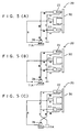
- Fig. 5(A) to Fig. 5(C) are summary views for showing molding method
according to the first embodiment;
- Fig. 6 is a cross section showing primary portion of the injection
molding unit indicating a condition immediately after loading the molten resin
into a cavity;
- Fig. 7 is a cross section showing primary portion of the injection
molding unit indicating a condition when the molten resin loaded in the cavity
- is pressurized;
- Fig. 8 is a side elevation showing entire arrangement of the injection
molding unit according to second embodiment of the preset embodiment;
- Fig. 9 is a front elevation of molding die drive unit according to the
second embodiment;
- Fig. 10 is a cross section taken along X-X line in Fig. 9 viewed from
arrow-indicated direction;
- Fig. 11 is a summarized block diagram showing detailed arrangement
of a hydraulic unit for driving the molding die drive unit;
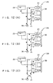
- Fig. 12(A) to Fig. 12(C) are summary views for showing molding
method according to the second embodiment;
- Fig. 13 is a cross section showing primary portion of the injection
molding unit of the second embodiment indicating a condition immediately
after loading the molten resin into a cavity;
- Fig. 14 is a cross section showing primary portion of the injection
molding unit of the second embodiment indicating a condition when the molten
resin loaded in the cavity is pressurized;
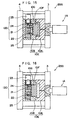
- Fig. 15 is a cross section showing primary portion of the injection
molding unit of third embodiment indicating a condition immediately after
loading the molten resin into a cavity;
- Fig. 16 is a cross section showing primary portion of the injection
molding unit of the third embodiment indicating a condition of expansion
molding of the molten resin loaded in the cavity;
- Fig. 17(A) to Fig. 17(C) are cross sections showing primary portion of
injection molding unit according to modification of the present invention;
- Fig. 18(A) to Fig. 18(C) are cross sections showing primary portions
of injection molding unit according to another modification of the present
invention; and
- Fig. 19 is a view similar to Fig. 1 showing a conventional example.
-
Best mode for Carrying out the Invention
-
An embodiment of the present invention will be described below with
reference to attached drawings. Incidentally, the same member as described
thus far will be attached with the same reference numerals to omit or simplify
description thereof.
-
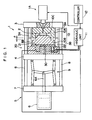
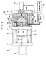
Fig. 1 shows an injection molding unit 1 according to first embodiment
of the present invention. The injection molding unit 1 conducts molding
process by a die 10 divided into a stationary die 10A and a movable die 10B.
The die 10 is closed while retaining moving distance of a dimension α as a
compression margin of the movable die 10B relative to the stationary die 10A,
so that a cavity 10C for loading a molten resin 2 injected from an injection unit
1A is formed therein. The loaded molten resin 2 is compressed to be filled
for rendering shape by pressing the movable die 10B by a molding die drive
unit 20 attached at the back of the movable die 10B.
-
The injection molding unit 1 has a stationary die plate 3 as a stationary
platen having the stationary die 10A fixed thereto, a movable die plate 4 as a
movable platen having the movable die 10B and the die driving unit 20, and a
clamp unit 5 for advancing the movable die plate 4 toward the stationary die
plate 3.
-
The movable die plate 4 is slidable along a tie-bar 8 spanning between
a stationary plate 7 having a clamping hydraulic cylinder unit 6 fixed thereto
and a stationary die plate 3.
-
The clamp unit 5 has a toggle mechanism 9 having a piston rod 6A of
the hydraulic cylinder unit 6, where pressing force of the hydraulic cylinder
unit 6 is strengthened by the toggle mechanism 9 to advance the movable die
plate 4 to clamp the die 10.
-
Clamping- pressure receiving blocks 3A and 3B are provided between
the movable die plate 4 and the stationary die plate 3. The clamping-pressure
receiving block 3A provided on the stationary die plate 3 side abuts to the
pressure-receiving block 3B provided on the movable die plate 4 side to
receive high-pressure clamping force of the toggle mechanism 9. Degree of
parallelization between the die plates 3 and 4 can be secured by the
clamping- pressure receiving blocks 3A and 3B.
-
The molding die drive unit 20 has a large-diameter main cylinder unit.
21 attached between the movable die 10B and the movable die plate 4, a
small-diameter sub cylinder unit 22 disposed around the main cylinder unit 21,
a hydraulic unit 11 for driving the cylinder units 21 and 22, and a controller 12
for controlling the die driving unit 20.
-
Detailed arrangement of the molding die drive unit 20 is shown in Fig.
2 to Fig. 4.
-
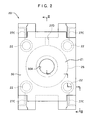
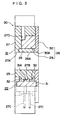
Fig. 2 is a front elevation of the molding die drive unit 20, Fig. 3 is a
cross section taken along III-III line in Fig. 2 viewed in arrow-indicating
direction, and Fig. 4 is a summarized block diagram showing a hydraulic unit
11 for driving the molding die drive unit 20.
-
In Fig. 2 and 3, the main cylinder unit 21 includes a cylinder member
25 and a piston member 26 advanceable and retractable relative to the cylinder
member 25.
-
The cylinder member 25 has a thick flat-plate member 27 having a
cylindrical cut-out 27A at a central portion thereof and a core member 28
provided at a central portion of the flat-plate member 27. An opening 28A is
formed on the core member 28 along an axis center of the main cylinder unit
21 continuously with the cut-out 27A.
-
The piston member 26 includes a ring-shaped member 29 slidably
disposed between the flat-plate member 27 and the core member 28, and an
attachment plate 30 fixed at an end of the ring-shaped member 29 for the
movable die 10B to be attached thereon. An opening 30A continuous with
the opening 28A is formed at a position of the attachment plate 30
corresponding to an axis center of the ring-shaped member 29.
-
The sub cylinder unit 22 is disposed around the main cylinder unit 21
in plural (with number of η. Four in the figure) spaced apart with each other,
which includes four cylinder portions 27B formed on the flat-plate member 27
and piston members 31 respectively disposed on the cylinder portion 27B to
be slidable. The cylinder portion 27B is connected to the hydraulic unit 11
through a flow channel 27C formed on the flat-plate member 27. Incidentally,
though disposition of the sub cylinder unit 22 is not restricted in the figure, the
sub cylinder units 22 are preferably disposed at a regular interval as shown in
the figure.
-
The piston member 31 has a projection 31A at a center thereof along a
circumferential direction. The projection 31A is prevented from being fallen
off by a pair of stopper 32 provided on the cylinder portion 27B. A flow
channel 27C for supplying hydraulic fluid between the stoppers 32 and the
projection 31A is formed on the flat plate member 27. The attachment plate
30 is fixed on an advancement-side end of the piston member 31.
-
The main cylinder 21 is advanced for pressurizing the molten resin
loaded in the cavity 10C, and the sub cylinder unit 22 is used not only for
pressurizing the molten resin, but also for moving the movable die 10B at a
high speed.
-
When an effective sectional area of the main cylinder unit 21 is A,
advancement-side effective sectional area of one sub cylinder unit 22 is B, and
retraction-side effective sectional area thereof is C, cylinder effective sectional
area of the movable die 10B during high-speed advancement is B*η, cylinder
effective sectional area of the movable die 10B during high-speed retraction is
C*η, and cylinder effective sectional area while pressurizing the molten resin
is (A+B*η). The cylinder area ratio is A>>B (any one of B>C, B=C, and
B<C), moving speed is high-speed advancement (retraction)>>pressurization,
and moving force is pressurization >> high-speed advancement (retraction).
-
A conduit line 27D for intercommunicating the hydraulic unit 11 and a
space between the cylinder member 25 and the piston member 26 is formed on
the flat-plate member 27.
-
In Fig. 4, the hydraulic unit 11 includes a hydraulic tank 11A having
the hydraulic fluid contained therein, a hydraulic pump 36 as a hydraulic fluid
feeder for supplying the hydraulic fluid from the hydraulic tank 11A, a main
cylinder driving mechanism 37 for driving the main cylinder unit 21 by the
hydraulic fluid supplied from the hydraulic pump 36, and a sub cylinder
driving mechanism 38 for driving the sub cylinder unit 22 by the hydraulic
fluid supplied by the hydraulic pump 36.
-
The main cylinder driving mechanism 37 has a main cylinder flow
channel 39 for circulating the hydraulic oil supplied from the hydraulic pump
36 to the main cylinder unit 21, and a main cylinder switching valve 40
provided to the main cylinder flow channel 39 for switching a position thereof
between a position for supplying the hydraulic fluid from the hydraulic pump
36 to the main cylinder unit 21 to advance the main cylinder unit 21 and a
position for blocking the supply of the hydraulic fluid to the main cylinder unit
21 and for returning the hydraulic fluid in the main cylinder unit 21 to the
hydraulic tank 11A.
-
The main cylinder flow channel 39 is connected to a flow channel 27D
provided to the molding die drive unit 20 through a hydraulic hose 41. The
flow channel 27D is in communication with a space between the cylinder
member 25 and the piston member 26 of the main cylinder unit 21. The main
cylinder switching valve 40 is a solenoid valve.
-
The sub cylinder driving mechanism 38 includes a sub cylinder flow
channel 43 provided between the hydraulic pump 36 and the sub cylinder unit
22, and a sub cylinder switching valve 44 provided to the flow channel 43.
-
The sub cylinder flow channel 43 is connected to the flow channel 27C
provided to the molding die drive unit 20 through a hydraulic hose 42.
-
The sub cylinder switching valve 44 is capable of switching between
three positions: a position for supplying the hydraulic fluid to the sub cylinder
unit 22 to advance the sub cylinder unit 22; a position for supplying hydraulic
fluid to the sub cylinder unit 22 to retract the sub cylinder unit 22; and a
neutral position.
-
Next, molding method (molding process) will be described below with
reference to Fig. 5 to Fig. 7.
-
First, the die 10 and the die driving unit 20 are attached to a
general-type injection molding unit 1 together with clamping- pressure
receiving blocks 3A and 3B to construct the injection compression molding
unit as shown in Fig. 1. At this time, the piston members 26 and 31 of the
molding die drive unit 20 are retracted.
-
When the injection molding unit 1 is driven, the clamp unit 5 is initially
driven to move the movable die plate 4 to the stationary die plate 3 and the die
10 is closed while retaining a compression margin of a dimension α on the
movable die 10B. At this time, the dimension α can be set within a range of,
for instance, 0.1mm to 100mm.
-
At this time, since the clamping- pressure receiving blocks 3A and 3B
are provided between the movable die plate 4 and the stationary die plate 3,
the die plates 3 and 4 go parallel when the toggle mechanism 9 of the clamp
unit 5 is fully extended and the parallelization of the die plates 3 and 4 are
stably maintained. Consequently, the stationary die 10A and the movable die
10B are stabilized.
-
Subsequently, the molten resin is injected from an injection nozzle of
the injection unit 1A to the internal cavity 10C of the die 10 so as not to fill the
cavity.
-
The injected molten resin is thermoplastic, which may be
general-purpose resin such as polyethylene, polypropylene, polystyrene, ABS,
engineering plastics such as polycarbonate, polyamide, polyacetal, and
compounds of the above resins with reinforcing agent such as glass fiber,
carbon fiber and organic fiber, bulking agent such as talc and various additives,
including all polymeric material capable of using for injection molding.
-
After a predetermined time passes from initiating injection of the
injection unit 1A or when an injection screw provided in the injection unit 1A
reaches a predetermined position, the molding die drive unit 20 is driven.
The drive of the molding die drive unit 20 may be conducted after injecting the
resin or during injection, and the resin injection amount to the cavity 10C of
the die 10 can be voluntarily set.
-
Since the internal molten resin is not filled in the entire cavity and large
force is not required for moving the movable die 10B when the drive of the
molding die drive unit 20 is started, driving speed takes precedence over
driving force. In other words, the four sub cylinder units 22 are advanced to
advance the movable die 10B at a high speed.
-
Accordingly, the main cylinder flow channel 39 is intercommunicated
with the hydraulic tank 11A by the main cylinder switching valve 40 and the
position of the sub cylinder switching valve 44 is switched to supply the
hydraulic fluid to the sub cylinder unit 22 to advance the sub cylinder unit 22.
-
Then, as shown in Fig. 5(A), the hydraulic fluid is fed from the
hydraulic pump 36 to the sub cylinder unit 22, so that the attachment plate 30
having the movable die 10B attached thereon is advanced at a high speed by
the sub cylinder unit 22. Though an advancing force is generated to the
piston member 26 of the main cylinder unit 21 in accordance with the
advancement of the attachment plate 30, since the hydraulic fluid contained in
the hydraulic tank 11A is flown into the main cylinder unit 21 through the
conduit line 27D by switching the switching valve 40, the piston member 26 is
advanced smoothly.
-
When the movable die 10B advances at a degree, the molten resin
loaded in the cavity 10C of the die 10 is pressurized.
-
For the purpose, the main cylinder switching valve 40 is operated to
switch the position thereof to intercommunicate the main cylinder flow
channel 39 with the hydraulic pump 36.
-
Then, as shown in Fig. 5(B), the hydraulic fluid is fed from the
hydraulic pump 36 not only to the sub cylinder unit 22 but also to the main
cylinder unit 21, so that large force by the cylinder units 21 and 22 works on
the movable die 10B to fill the entirety of the cavity 10C, with molten resin
loaded to the cavity 10C between the movable die 10B and the stationary die
10A as shown in Fig. 7 from a condition being concentrated to a central
portion of the cavity shown in Fig. 6.
-
While applying pressure to the molten resin by the molding die drive
unit 20, the molten resin is cooled and solidified for a predetermined time
period. When the molten resin is sufficiently solidifies alter the
predetermined time, the clamp unit 5 is driven to retract the movable die plate
4 to open the die 10. Subsequently, the molding product is ejected from the
inside of the die 10 to complete the molding process. Thereafter, the
injection compression molding process is repeated as necessary.
-
The cylinder units 21 and 22 are retracted during a time period from
initiation of retracting the movable die plate 4 to initiation of next injection
molding process.
-
For the purpose, the position of the main cylinder switching valve 40 is
switched to intercommunicate the main cylinder flow channel 39 with the
hydraulic tank 11A, and the position of the sub cylinder switching valve 44 is
switched to supply the hydraulic fluid to the sub cylinder unit 22 to retract the
sub cylinder unit 22.
-
Then, as shown in Fig. 5(C), the hydraulic fluid is fed from the
hydraulic pump 36 to the sub cylinder unit 22 to retract the attachment plate
30 having the movable die 10B attached thereon at a high speed by the sub
cylinder unit 22. In accordance with the retraction of the attachment plate 30,
a force for retracting the piston member 26 of the main cylinder unit 212 is
caused. However, since the hydraulic fluid contained in the main cylinder
unit 21 by the switching valve 40 is returned to the inside of the hydraulic tank
11A through the conduit line 27D, the piston member 26 is retracted smoothly.
-
According to the above-described first embodiment, following effects
can be obtained.
- 1) Since the molding die drive unit 20 includes the main cylinder unit
21 and the sub cylinder unit 22 for advancing and retracting the movable die
10B to the cavity 10C, injection compression molding is possible by
advancing the movable die after injecting the molten resin into the cavity 10C.
- 2) Since the large-diameter main cylinder unit 21 is mainly used for
pressurizing the molten resin, uniformity of the force applied to the entirety of
the molten resin can be secured and parallelization between the movable die
10B and the stationary die 10A can be secured.
- 3) Since the main cylinder unit 21 is advanced only for pressurizing the
molten resin and only the sub cylinder unit 22 is driven for retracting the
movable die 10B, the operation circuit for retracting the main cylinder unit 21
is unnecessary. In other words, since the main cylinder unit 21 is a
single-drive cylinder for advancement and the retraction is conducted by the
sub cylinder unit 22, the cylinder units 21 and 22 can be made to be a thin unit
having large mechanical output, which can be attached to an ordinary injection
molding unit together with the die 10.
- 4) Since the sub cylinder units 22 can be disposed mutually at an equal
interval around a center of the main cylinder unit 21, the movable die 10B can
be appropriately advanced and retracted without being inclined.
- 5) Since, in the first embodiment, the sub cylinder unit 22 is connected
to the sub cylinder driving mechanism 38, which includes the sub cylinder
flow channel 43 provided between the hydraulic pump 36 and the sub cylinder
unit 22 and the sub cylinder switching valve 44 provided to the flow channel
43 for switching the position thereof for supplying the hydraulic fluid to the
sub cylinder unit 22 to advance the sub cylinder unit 22 and for supplying the
hydraulic fluid to the sub cylinder unit 22 to retract the sub cylinder unit 212,
the sub cylinder unit 22 can be easily advanced and retracted only by
switching the sub cylinder switching valve 44, thereby rapidly conducting
molding process.
- 6) Since the main cylinder unit 21 is connected to the main cylinder
driving mechanism 37, which includes the main cylinder flow channel 39 for
supplying the hydraulic fluid supplied from the hydraulic pump 36 to the main
cylinder unit 21 and the main cylinder switching valve 40 provided to the main
cylinder flow channel 39 for switching intercommunication of the main
cylinder unit 21 and the hydraulic pump 36 or the hydraulic tank 11A, the
main cylinder unit 21 can be easily advanced by operating the switching valve
40, thereby rapidly conducting molding process.
- 7) In the first embodiment, since the openings 28A and 30A are
formed along the axis center of the main cylinder unit 21, an ejector rod (not
shown) can be inserted from the openings 28A and 30A, thereby facilitating
ejection of the molding product.
- 8) Since the injection molding unit 1 of the first embodiment has a
molding die driving device 20 attached between the movable platen 4 for the
movable die 10B to be mounted and the movable die 10B and the
clamping- pressure receiving blocks 3A and 3B provided between the movable
platen 4 and the stationary platen 3, the parallelization between the stationary
platen 3 and the movable platen 4, in the end, the parallelization between the
stationary die 10A and the movable die 10B attached to the platens 3 and 4
can be secured, thereby enabling appropriate injection compression molding.
Next, second embodiment according to the present invention will be
described below with reference to Fig. 8 to Fig. 14.The second embodiment differs from the first embodiment in having a
reserve tank in addition to the hydraulic tank 11A and a on-off valve provided
adjacent to the reserve tank, and the other arrangement is the same as the first
embodiment. In the following description of the second embodiment, the
same reference numerals will be applied to the components identical with or
similar to the first embodiment to omit or simplify the description therefor.Fig. 8 shows an injection molding unit 100 according to the second
embodiment.As in the first embodiment, the injection molding unit 100 includes the
die 10, the stationary die plate 3, the movable die plate 4 and the clamp unit 5,
and further includes a molding die drive unit 120.The molding die drive unit 120 has the main cylinder unit 21, the sub
cylinder unit 22, a reserve tank 23 in communication with the main cylinder
unit 21, an on-off valve 24 for allowing or blocking a circulation of the
hydraulic fluid between the reserve tank 23 and the main cylinder unit 21, the
hydraulic unit 11 for driving the cylinder units 21 and 22, and the controller 12
for controlling the die driving unit 20.Detailed arrangement of the molding die drive unit 120 is shown in Fig.
9 to Fig. 11.Fig. 9 is a front elevation of the molding die drive unit 120, Fig. 10 is a
cross section taken along X-X line in Fig. 9 viewed in arrow-indicating
direction, and Fig. 11 is a summarized block diagram showing a hydraulic unit
11 for driving the molding die drive unit 120.In Fig. 9 and 10, the main cylinder unit 21 and the sub cylinder unit 22
have the same basic structure as the main cylinder unit 21 and the sub cylinder
unit 22 of the first embodiment.More specifically, the main cylinder unit 21 includes a cylinder
member 25 and a piston member 26, and the cylinder member 25 has a thick
flat-plate member 27 having a cylindrical cut-out 27A at a central portion
thereof and a core member 28 provided at the center of the flat-plate member
27. An opening 28A is formed on the core member 28 along an axis center
of the main cylinder unit 21 continuously with the cut-out 27A. The piston
member 26 includes a ring-shaped member 29 slidably disposed between the
flat-plate member 27 and the core member 28, and an attachment plate 30
fixed at an end of the ring-shaped member 29 for the movable die 10B to be
attached thereon. An opening 30A continuous with the opening 28A is
formed at a position of the attachment plate 30 corresponding to an axis center
of the ring-shaped member 29.The sub cylinder unit 22 is disposed around the main cylinder unit 21
in plural (with number of η. Four in the figure) spaced apart with each other,
which includes four cylinder portion 27B formed on the flat-plate member 27
and a piston member 31 disposed on the cylinder portion 27B to be slidable
respectively. The cylinder portion 27B is connected to the hydraulic unit 11
through a flow channel 27C formed on the flat-plate member 27. Incidentally,
though disposition of the sub cylinder unit 22 is not restricted in the figure, the
sub cylinder units 22 are preferably disposed at a regular interval as shown in
the figure.The piston member 31 has a projection 31A at a center thereof along a
circumferential direction. The projection 31A is prevented from being fallen
off by a pair of stopper 32 provided on the cylinder portion 27B. A flow
channel 27C for supplying hydraulic fluid between the stoppers 32 and the
projection 31A is formed on the flat plate member 27. The attachment plate
30 is fixed on an advancing-side end of the piston member 31.When an effective sectional area of the main cylinder unit 21 is A,
advancement side effective sectional area of one sub cylinder unit 22 is B, and
retraction side effective sectional area thereof is C, cylinder effective sectional
area of the movable die 10B during high-speed advancement is B*η, cylinder
effective sectional area of the movable die 10B during high-speed retraction is
C*η, and cylinder effective sectional area while pressurizing the molten resin
is (A+B*η). The cylinder area ratio is A>>B (any one of B>C, B=C, and
B<C), moving speed is high-speed advancement (retraction)>>pressurization,
and moving force is pressurization >> high-speed advancement (refraction).The reserve tank 23 is disposed adjacently to the main cylinder unit 21,
the reserve tank 23 including a bottomed cylindrical casing 33 directly fixed
on an upper surface of the flat-plate member 27 containing the hydraulic fluid
thereinside, an oil-level pressing piston member 34 disposed in the casing 33
ascending and descending in accordance with oil level of the hydraulic fluid
and a lid member 35 attached to an upper end surface of the casing 33.A conduit line 27E for intercommunicating the internal space of the
reserve tank 23 containing the hydraulic fluid and a space of the cylinder
member 25 and the piston member 26 is formed on the flat-plate member 27,
the conduit line 27E having the on-off valve 24. The on-off valve 24 is a
prefill valve to be opened in receiving a pilot hydraulic pressure and closed in
the other occasion.In Fig. 11, the hydraulic unit 11 includes a hydraulic tank 11A, a
hydraulic pump 36 for supplying hydraulic fluid contained in the hydraulic
tank 11A, a main cylinder driving mechanism 37 for driving the main cylinder
unit 21 by the hydraulic fluid supplied from the hydraulic pump 36, and a sub
cylinder driving mechanism 38 for driving the sub cylinder unit 22 by the
hydraulic fluid supplied by the hydraulic pump 36.The main cylinder driving mechanism 37 has a main cylinder flow
channel 39 for circulating the hydraulic oil supplied from the hydraulic pump
36 to the main cylinder unit 21, and a main cylinder on-off valve 50 for
blocking or allowing the circulation of the hydraulic fluid in the main cylinder
flow channel 39 and a main cylinder control valve 51 for controllably opening
and shutting the on-off valve 24 of the reserve tank 23 and for blocking or
allowing the circulation of the hydraulic oil in the main cylinder flow channel
39.The main cylinder flow channel 39 is connected to a flow channel 27D
provided to the molding die drive unit 120 through a hydraulic hose 41. The
main cylinder switching valve 40 is a solenoid valve having a check-valve
50A.The main cylinder control valve 51 is a solenoid valve capable of
switching three positions: a position for feeding pilot hydraulic pressure to the
on-off valve 24 and for blocking the circulation of the hydraulic fluid in the
main cylinder flow channel 39; a position for allowing the circulation of the
hydraulic oil in the main cylinder flow channel 39 without feeding the pilot
hydraulic pressure; and a neutral position.The sub cylinder driving mechanism 38 includes a sub cylinder flow
channel 43 provided between the hydraulic pump 36 and the sub cylinder unit
22, and a sub cylinder switching valve 44 provided to the flow channel 43.The sub cylinder flow channel 43 is connected to the flow channel 27C
provided to the molding die drive unit 120 through a hydraulic hose 42.The sub cylinder switching valve 44 is capable of switching between
three positions: a position for supplying the hydraulic fluid to the sub cylinder
unit 22 to advance the sub cylinder unit 22; a position for supplying hydraulic
fluid to the sub cylinder unit 22 to retract the sub cylinder unit 22; and a
neutral position.Next, molding method (molding process) will be described with
reference to Fig. 12 to Fig. 14. Basic molding process of the second
embodiment is the same as the first embodiment.First as shown in Fig. 8, the die 10 and the die driving unit 20 are
attached to a general-type injection molding unit 100 together with
clamping- pressure receiving blocks 3A and 3B. At this time, the piston
members 26 and 31 of the molding die drive unit 120 are retracted.When the injection molding unit 100 is driven, the clamp unit 5 is
initially driven to move the movable die plate 4 to the stationary die plate 3
and the die 10 is closed while retaining a compression margin of a dimension α
on the movable die 10B. At this time, the dimension α can be set within a
range of, for instance, 0.1mm to 100mm.At this time, since the clamping- pressure receiving blocks 3A and 3B
are provided between the movable die plate 4 and the stationary die plate 3,
the die plate 3 and 4 are made parallel when the toggle mechanism 9 of the
clamp unit 5 is fully extended and the parallelization of the die plates 3 and 4
are stably maintained. Consequently, the stationary die 10A and the movable
die 10B are stabilized.Subsequently, the molten resin is injected from an injection nozzle of
the injection unit 1A to the internal cavity 10C of the die 10 so as not to fill the
cavity. The injected molten resin is thermoplastic in the same manner as the
first embodiment.After a predetermined time passes from initiating injection of the
injection unit 1A or when an injection screw provided in the injection unit 1A
reaches a predetermined position, the molding die drive unit 120 is driven.
The drive of the molding die drive unit 120 may be conducted after injecting
the resin or during injection, and the resin injection amount to the cavity 10C
of the die 10 can be voluntarily set.Since the internal molten resin is not filled in the entire cavity and large
force is not required for moving the movable die 10B when the drive of the
molding die drive unit 120 is started, driving speed takes precedence over
driving force. In other words, the four sub cylinder units 22 are advanced to
advance the movable die 10B at a high speed.Accordingly, the main cylinder flow channel 39 is shut by the main
cylinder on-off valve 50 so that the pilot hydraulic pressure is fed to the on-off
valve 24 by the main cylinder control valve 51 and the position thereof is
switched to block circulation of the hydraulic fluid in the main cylinder flow
channel 39. And the position of the sub cylinder switching valve 44 is
switched to supply the hydraulic fluid to the sub cylinder unit 22 to advance
the sub cylinder unit 22.Then, as shown in Fig. 12(A), the hydraulic fluid is fed from the
hydraulic pump 36 to the sub cylinder unit 22, so that the attachment plate 30
having the movable die 10B attached thereon is advanced at a high speed by
the sub cylinder unit 22. Though an advancing force is generated to the
piston member 26 of the main cylinder unit 21 in accordance with the
advancement of the attachment plate 30, since the on-off valve 24 is open and
the hydraulic fluid contained in the reserve tank 23 flows into the main
cylinder unit 21 through the conduit line 27E, the piston member 26 is
advanced smoothly.When the movable die 10B advances at a degree, the molten resin
loaded in the cavity 10C of the die 10 is pressurized. For the purpose, the
main cylinder on-off valve 50 is opened to open the main cylinder flow
channel 39 and switch the position thereof to a position allowing the
circulation of the hydraulic fluid in the main cylinder flow channel 39 without
feeding the pilot hydraulic pressure to the on-off valve 24 by the main cylinder
control valve 51.Then, as shown in Fig. 12(B), the on-off valve 24 is closed to shut the
circulation of the hydraulic fluid between the reserve tank 23 and the main
cylinder unit 21. Further, the hydraulic fluid is also supplied to the main
cylinder unit 21 as well as the sub cylinder unit 22, so that large force by the
cylinder units 21 and 22 works on the movable die 10B to fill the entirety of
the cavity 10C, from a condition shown in Fig. 13 being concentrated to a
central portion of the cavity, with molten resin loaded to the cavity 10C
between the movable die 10B and the stationary die 10A as shown in Fig. 14.While applying pressure to the molten resin by the molding die drive
unit 120, cooling and solidification of the molten resin is conducted for a
predetermined time period. When the molten resin is sufficiently solidifies
after the predetermined time, the clamp unit 5 is driven to retract the movable
die plate 4 to open the die 10. Subsequently, the molding product is ejected
from the inside of the die 10 to complete the molding process. Thereafter,
the injection compression molding process is repeated as necessary.The cylinder units 21 and 22 are retracted during a time period from
initiation of retracting the movable die plate 4 to initiation of next injection
molding process.For the purpose, the main cylinder flow channel 39 is shut by the main
cylinder on-off valve 50 to switch the position thereof to feed the pilot
hydraulic pressure to the on-off valve 24 and to block the circulation of the
hydraulic fluid in the main cylinder flow channel 39, and the position of the
sub cylinder switching valve 44 is switched to supply the hydraulic fluid to the
sub cylinder unit 22 to retract the sub cylinder unit 22.Then, as shown in Fig. 12(C), the hydraulic fluid is fed from the
hydraulic pump 36 to the sub cylinder unit 22 to retract the attachment plate
30 having the movable die 10B attached thereon at a high speed by the sub
cylinder unit 22. In accordance with the retraction of the attachment plate 30,
a force for retracting the piston member 26 of the main cylinder unit 212 is
caused. However, since the on-off valve 24 is opened and the hydraulic fluid
contained in the main cylinder unit 21 is returned into the reserve tank 23
through the conduit line 27E, the piston member 26 is retracted smoothly.According to the above-described second embodiment, following
effect can be obtained as well as the effects 1) to 8) of the first embodiment.
- 9) In the second embodiment, since the reserve tank 23 is in
communication with the main cylinder unit 21 via the on-off valve 24, the
exclusive reserve tank 23 is used for supplying the hydraulic fluid to the main
cylinder unit 21 and returning the hydraulic fluid from the main cylinder unit
21 when the main cylinder unit 21 is advanced and retracted in accordance
with the advancement and the retraction of the sub cylinder unit 22.
Accordingly, installation of the reserve tank 23 to the molding die drive unit
20 enables smooth circulation of the hydraulic fluid between the reserve tank
23 and the main cylinder unit 21 in high-speed advancement and retraction of
the movable die 10B to improve responsivity of the die movement and, in
addition thereto, the size of the outside hydraulic tank and the hydraulic pump
can be reduced.
-
-
Next, third embodiment of the present invention will be described with
reference to Fig. 15 and 16. In the third embodiment, a part of the movable
die 10B is advanced and retracted by the die driving unit 20 and other
arrangement of the third embodiment is the same as the second embodiment.
In the description of the third embodiment, the same reference numerals will
be attached to the component identical with or similar to the first and the
second embodiments to omit or simplify the description therefor.
-
Fig. 15 and Fig. 16 are cross sections respectively showing primary
portion of an injection molding unit 200 having the molding die drive unit 120
installed therein. The basic arrangement of the injection molding unit 200 of
the third embodiment such as the clamp unit 5, the hydraulic cylinder unit 6
and toggle mechanism 9 is the same as the injection molding unit 1 and 100 of
the first and the second embodiment.
-
In Fig. 15, the movable die 10B has a die body 10G fixed to the
cylinder member 25 of the molding die drive unit 120 and having an opening
at a central portion thereof, and a slide die 10F disposed at the opening of the
die body 10G and being slidable relative to the cavity 10C.
-
The slide die 10F is fixed to the attachment plate 30 of the molding die
drive unit 120.
-
The molding die drive unit 120 includes a large-diameter main cylinder
unit 21, a small-diameter sub cylinder unit 22 disposed around the main
cylinder unit 21, a reserve tank 23 in communication with the main cylinder
unit 21, an on-off valve 24 for allowing and blocking the circulation of the
hydraulic fluid between the reserve tank 23 and the main cylinder unit 21, a
hydraulic unit 11 for driving the cylinder unit 21 and 22 (see Fig. 8), and a
controller 12 for controlling the molding die drive unit 20 (see Fig. 8).
-
In the third embodiment, expansible molten resin such as a resin
including foaming agent and a resin including glass fiber can be injected into
the cavity 10C of the die 10E as well as a normal molten resin.
-
When the molten resin having expansibility is used, as shown in Fig.
15, the molten resin is injected inside the die 10E while the slide die 10F
advances to the stationary die 10A to fill the cavity in the die 10E with the
molten resin. Subsequently, as shown in Fig. 16, the slide die 10F is
retracted from the stationary die 10A to enlarge the cavity 10C to promote
foaming of the foaming agent, thereby producing light-weight molding product
by the expansion.
-
In the third embodiment, effects similar to 2) to 9) of the second
embodiment can be obtained and, in addition thereto, 10) effect being capable
of partially applying compressive force to the molten resin injected into the die
10E and enlarging cavity 10C can be obtained.
-
Next, the effect of the present invention will be described below based
on specific examples.
[Example 1]
-
The present example was an experiment in which the injection molding
unit 1, the molding die drive unit 20 and the molding process according to the
first embodiment was used.
-
Incidentally, the die used in the Example 1 was for forming a
rectangular-plate molding product and had a side gate at a center of a short
edge of the cavity. Respective dimensions of the molding products were
1000mm (vertical) * 500mm (horizontal) * 2mm (thick).
-
A general-purpose horizontal injection molding unit having clamping
force of 850t was used as the injection molding unit. The effective cross
section A of the main cylinder unit 21 was 3060cm2, advancement-side
effective cross section B of the sub cylinder unit 22 was 180cm2,
retraction-side effective cross section C of the sub cylinder unit 22 was
230cm2, and the number η of the sub cylinder unit 22 was four.
[Example 2]
-
The present example was an experiment in which the injection molding
unit 100, molding die drive unit 120 and the molding process according to the
second embodiment were used to produce molding product.
-
Incidentally, the die used in the present embodiment was for forming a
rectangular-plate molding product and had a side gate at a center of a short
edge of the cavity. Respective dimensions of the molding products were
1000mm (vertical) * 500mm (horizontal;) * 2mm (thick).
-
The general-purpose horizontal injection molding unit having clamping
force of 850t was used as the injection molding unit as in the Example 1.
The effective cross section A of the main cylinder unit 21, the
advancement-side effective cross section B of the sub cylinder unit 22, the
retraction-side effective cross section C and the number η of the sub cylinder
unit 22 ware the same as the Example 1.
[Comparison 1]
-
Comparison 1 was an experiment to obtain the same molding product
by the same die and the same process as the above-described Example 1 using
a conventional multi-cylinder clamping type injection compression molding
machine.
-
The multi-cylinder type injection compression molding machine of the
comparison 1 had a hydraulic cylinder unit integrally provided on four corners
of a stationary die-plate. The piston of the hydraulic cylinder unit was
connected to an end of a tie-bar. The piston was driven by hydraulic force to
attract the movable die-plate to apply compressive force to the molten resin
injected into the die.
[Comparison 2]
-
The comparison 2 was an experiment to obtain the same molding
product by the same die and the same process as the above-described Example
1 using the injection molding unit and the compression unit 75 shown in Fig.
19.
[Common Molding Condition]
-
Following common material and molding condition were employed in
the above-described Examples 1 and 2 and the
Comparisons 1 and 2.
- (1) Material: polypropylene (MI = 24g/10min; 230°C, 2.16kgf, manufactured
by Idemitsu Petrochemical Co., Ltd. Tradename: IDEMITSU PP J-950HP)
- (2) Molding condition
- 1 ○ Molding temperature
- : 220°C (injection cylinder temperature)
- 2 ○ Die temperature
- : 40 °C
- 3 ○ Resin Injection Time
- : 3.0 seconds
- 4 ○ Resin Injection Pressure
- : 90kg/cm2 (gauge hydraulic pressure)
- 5 ○ Cooling Time
- : 30 seconds
- 6 ○ Compression Margin (dimension α in Fig 1 )
- : 5mm
- 7 ○ Compression Initiation Timing
- : after 2.8 second (from injection
initiation)
- 8 ○ Compression Speed
- : 10mm/sec
- 9 ○ Compression Force S
- : 400t (maintained to be constant until
completion of cooling)
-
[Experiment Result]
-
Though unbalanced load relative to the die center was generated in the
Example 1 on account of the side gate, the die closed in parallel because of
being compressed by the large-diameter hydraulic cylinder unit, thereby
obtaining molding products having uniform thickness and no warp.
Discharge pressure P of oil of the hydraulic unit was 125kg/cm2 and discharge
flow rate Q was 43 l/min.
-
The mechanical efficiently can be obtained by an equation of
S/{(A+B*n)*P*0.001}, specifically, 400/{(3060+180*4)*125*0.001} =
400/472.5 = 0.85 = 85%.
-
In Example 2, though the die had only one side gate as in the Example
1 and the load was unbalancedly applied to a position off the die center, the
die could be closed in parallel since the movable die was driven by the
large-diameter hydraulic cylinder unit.
-
Accordingly, a molding product having less warp and deformation and
approximately uniform thickness could be obtained.
-
The discharge pressure P of the oil of the hydraulic unit was
120kg/cm2 and discharge flow rate was 43l/min.
-
The mechanical efficiency was obtained by an equation of
S/{(A+B*n)*P*0.001}, which specifically was 88%.
-
In comparison 1, since the die had only one side gate and the load was
unbalancedly applied to a position off the die center in advancing the movable
die, parallel accuracy of the movable die relative to the stationary die cannot
be maintained thereby causing deviation of compressive force applied to the
molten resin in the die.
-
Accordingly, the thickness of the molding was 2.2mm on the side gate
and 1.9mm at the flow end on the other side, thereby not obtaining molding
product having uniform thickness.
-
In comparison 2, the parallel accuracy of the movable die relative to
the stationary die could be maintained as in the above Examples and no
deviation was caused to the compression force applied to the molten resin in
the die, so that a molding product having less warp and deformation with
approximately uniform thickness could be obtained. However, the discharge
pressure P of the oil of the hydraulic unit was 165kg/cm2 (mechanical
efficiency 60%) and discharge flow rate of 200l/min was required.
-
Though preferred embodiments and examples of the present invention
has been described in the above, the scope of the present invention is not
limited to the embodiments and examples but includes various improvement
and modification of design is possible as long as they do not depart from the
gist of the present invention.
-
For instance, the entire movable die 10B of the first and the second
embodiment and a part of the movable die 10B of the third embodiment are
advanced and retracted relative to the cavity 10C. However, entire or a part
of the stationary die 10A may be advanced and retracted relative to the cavity
10C in the present invention.
-
Specifically, a part of the stationary die 10A may be advanced and
retracted by the die driving unit 20 as respectively shown in Fig. 17 and 18.
-
Fig. 17 is a cross section showing a primary portion of an injection
molding unit 300 having the molding die drive unit 120 installed therein. The
injection molding unit 300 shown in Fig. 17 has a basic structure such as the
clamp unit 5, the hydraulic cylinder unit 6 and the toggle mechanism 9
identical with the injection molding unit 1 and 100 of the first and second
embodiment.
-
In Fig. 17, the stationary die 10A has a die body 10H attached to the
cylinder unit 25 of the molding die drive unit and having an opening at a
central portion thereof, and a slide die 10J disposed at the opening of the die
body 10H slidably toward the cavity 10C. The slide die 10J is fixed to the
attachment plate 30.
-
The operation process of the injection molding unit 300 is shown in
Fig. 17 (A) to (C). When the slide die 10J of the stationary die 10A is at a
retracted position relative to the cavity 10C as in Fig. 17(A), the molten resin
is injected into the cavity 10C by the injection unit 1A as shown in Fig. 17(B).
Subsequently, the slide die 10J is advanced to the cavity 10C by driving the
molding die drive unit 120. At this time, the injection unit 1A advances so
that a nozzle portion thereof follows the slide die 10J.
-
Fig. 18 is a cross section showing primary portion of the injection
molding unit 400 having the molding die drive unit 120 installed therein. The
injection molding unit 400 shown in Fig. 18 has the same basic structure as the
injection molding unit 300 shown in Fig. 18 and the operation step thereof is
different.
-
The operation process of the injection molding unit 400 is shown in
Fig. 18 (A) to (C). In Fig. 18(A), the molten resin is injected into the cavity
10C by the injection unit 1A when the slide die 10J of the stationary die 10A
is advanced to the cavity 10C being spaced apart at a predetermined gap. At
this time, molten resin having expansibility such as resin added with foaming
agent and resin including glass fiber is injected into the cavity 10C.
-
Subsequently, as shown in Fig. 18 (B), the nozzle portion of the
injection unit 1A is refracted from the die 10E and the slide die 10J is refracted
from the cavity 10C by driving the molding die drive unit 120 as shown in Fig.
18(C).
-
Incidentally, the sub cylinder unit 22 is not shown in Fig. 17 and Fig.
18.
-
Further, the molten resin may be loaded into the cavity 10C while
advancing the movable die 10B and the movable die 10B may be retracted by
the molding die driving device 20 to conduct injection expansion molding
thereafter.
-
On the other hand, the molten resin may be loaded into the cavity 10C
while retracting the slide die 10F and the slide die 10F may be advanced
thereafter to conduct the injection compression molding.
-
Specifically, any one of following (1) to (5) may be adopted for the
molding method of the present invention:
- (1) Injection compression molding method.
- (2) Injecting the molten resin to a die having surface member disposed
thereinside beforehand to obtain the laminated molding.
- (3) Adding foaming agent to the molten resin to be injected and loaded
for obtaining foamed molding product.
- (4) Injecting molten resin having expansibility by entanglement of fiber
mixed therein and enlarging the cavity to expand the molten resin in the die to
obtain light-weight molding product.
- (5) Injecting gas into the molten resin loaded in the cavity and
enlarging the cavity to obtain molding product having large-volume hollow
portion.
-
-
In other words, any molding method can be used as long as at least a
portion of the movable die and the stationary die are relatively moved to freely
contract and extend the die interval during molding process in molding the
molten resin.
-
Accordingly, the present invention can be applied to any molding
method having a step of injecting while narrowing and enlarging the gap,
applying compressive force to the molten resin, and enlarging and contracting
the gap after initiating the injection.
-
Further, though the hydraulic fluid contained in the hydraulic tank 11A
structuring the hydraulic unit 11 is fed to the main cylinder unit 21 in the first
embodiment, a separate tank containing hydraulic fluid may be independently
provided as well as the hydraulic tank 11A and the hydraulic fluid contained in
the tank may be fed to the main cylinder unit 21.
[Industrial Applicability]
-
As described above, the molding die drive unit, the molding unit
having the molding die drive unit installed therein and the molding method
using the molding unit according to the present invention is useful for injection
molding, injection compression molding, press molding, large blow
gas-injection molding, multi-layered molding, foam molding and expansion
molding of glass-fiber containing resin. Especially, the present invention is
suitable for molding in which at least a portion of the die is advanced and
refracted to change the cavity volume provided in the die for compressing or
expanding (enlarging volume) the resin in the die.