EP1001264A1 - Moisture indicator label - Google Patents
Moisture indicator label Download PDFInfo
- Publication number
- EP1001264A1 EP1001264A1 EP99122501A EP99122501A EP1001264A1 EP 1001264 A1 EP1001264 A1 EP 1001264A1 EP 99122501 A EP99122501 A EP 99122501A EP 99122501 A EP99122501 A EP 99122501A EP 1001264 A1 EP1001264 A1 EP 1001264A1
- Authority
- EP
- European Patent Office
- Prior art keywords
- water
- water sinking
- confirmation
- hole
- sinking
- Prior art date
- Legal status (The legal status is an assumption and is not a legal conclusion. Google has not performed a legal analysis and makes no representation as to the accuracy of the status listed.)
- Granted
Links
Images


Classifications
-
- G—PHYSICS
- G09—EDUCATION; CRYPTOGRAPHY; DISPLAY; ADVERTISING; SEALS
- G09F—DISPLAYING; ADVERTISING; SIGNS; LABELS OR NAME-PLATES; SEALS
- G09F3/00—Labels, tag tickets, or similar identification or indication means; Seals; Postage or like stamps
- G09F3/02—Forms or constructions
- G09F3/0291—Labels or tickets undergoing a change under particular conditions, e.g. heat, radiation, passage of time
-
- G—PHYSICS
- G01—MEASURING; TESTING
- G01D—MEASURING NOT SPECIALLY ADAPTED FOR A SPECIFIC VARIABLE; ARRANGEMENTS FOR MEASURING TWO OR MORE VARIABLES NOT COVERED IN A SINGLE OTHER SUBCLASS; TARIFF METERING APPARATUS; MEASURING OR TESTING NOT OTHERWISE PROVIDED FOR
- G01D3/00—Indicating or recording apparatus with provision for the special purposes referred to in the subgroups
- G01D3/08—Indicating or recording apparatus with provision for the special purposes referred to in the subgroups with provision for safeguarding the apparatus, e.g. against abnormal operation, against breakdown
-
- G—PHYSICS
- G01—MEASURING; TESTING
- G01N—INVESTIGATING OR ANALYSING MATERIALS BY DETERMINING THEIR CHEMICAL OR PHYSICAL PROPERTIES
- G01N31/00—Investigating or analysing non-biological materials by the use of the chemical methods specified in the subgroup; Apparatus specially adapted for such methods
- G01N31/22—Investigating or analysing non-biological materials by the use of the chemical methods specified in the subgroup; Apparatus specially adapted for such methods using chemical indicators
- G01N31/222—Investigating or analysing non-biological materials by the use of the chemical methods specified in the subgroup; Apparatus specially adapted for such methods using chemical indicators for investigating moisture content
Definitions
- the present invention relates to a water sinking confirmation device and in particular, it relates to one to be used in a portable terminal device or the like, enabling judgment on whether or not the device has been sunk in water only by seeing a lower case.
- the water sinking confirmation device comprises an internal unit 61 with a water sinking confirmation seal 62 attached at a predetermined position, and a lower case 63 having a hole 64 formed at a predetermined position such that the water sinking confirmation seal 62 attached on the internal unit 61 is seen through a transparent sheet 65, attached together.
- the water sinking confirmation seal 62 is attached directly on a predetermined position of the internal unit 61 and the transparent sheet 65 is bonded or adhered to the lower case 63, surrounding the hole 64, the water sinking confirmation seal 62 and the transparent sheet 65 are not sealed closely, and thus a problem is involved in that the water sinking confirmation seal 62 may generate the state change when it is not sunk in water.
- an object of the invention is to provide a water sinking confirmation device enabling judgment on whether or not a portable terminal device or the like has been sunk in water only by seeing a lower case.
- a water sinking confirmation device comprising: a lower case provided with a hole for confirming water sinking; a double side coated adhesive member for bonding both sides, surrounding the hole; a transparent sheet allowing a state change of a water sinking confirmation seal seen through from a surface thereof; and the water sinking confirmation seal including a double side coated adhesive member disposed at both ends of the transparent sheet and a white plain paper, and the white plain paper applied with red color printing with a water-color ink at a center thereof.
- FIG. 1 is a cross-sectional view showing the configuration of a water sinking confirmation device according to an embodiment of the invention.
- FIG. 2 is a plan view of a water sinking confirmation seal according to the embodiment of the invention.
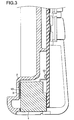
- FIG. 3 is a cross-sectional view showing the configuration of the water sinking confirmation device according to the embodiment of the invention used in a portable terminal device.
- FIG. 4 is an exploded perspective view showing the order of assembling the water sinking confirmation device according to the embodiment of the invention.
- FIG. 5 is a perspective view for explaining the configuration of the invention, corresponding to a conventional configuration.
- FIG. 6 is a perspective view showing the configuration of the conventional water sinking confirmation device.
- FIG. 1 is a cross-sectional view showing the configuration of a water sinking confirmation device according to the invention to be used in a portable terminal device, such as a portable phone device or a PHS.
- the water sinking confirmation device comprises a lower case 2 provided with a hole 3, a double side coated adhesive member 4 for bonding both sides, surrounding the hole 3, a transparent sheet 5 for blocking entrance of water from the hole 3 and allowing the state change of a water sinking confirmation seal 10 seen through from the surface thereof, and the water sinking confirmation seal 10 including a double side coated adhesive member 6 disposed at both ends of the transparent sheet 5 and a white plain paper 7, and the white plain paper 7 applied with red color printing 8 with a water-color ink at the center.
- the hole 3 is formed at a position not to be covered by another part mounted on the lower case 2, for example, above a holding member 1.
- FIG. 2 is a plan view of the water sinking confirmation seal 10, showing the state comprising the double side coated adhesive member 6 disposed below the transparent sheet 5, capable of bonding both sides at both end portions of the transparent sheet 5, and being applied with red color printing 8 with a water-color ink at the center. Moreover, as shown in the cross-sectional view of FIG. 1, since the double side coated adhesive member 6 is provided between the white plain paper 7 and the transparent sheet 5 so as to form a gap 9, consequently water can enter from the gap 9.
- FIG. 3 is a cross-sectional view of the configuration of the water sinking confirmation device used in a portable terminal device, such as a portable phone device.
- a portable terminal device such as a portable phone device.
- the water sinking confirmation device is provided in the lower case 2 on the holding member (external connector ) 1 attached on the lower part of the portable phone device, whether or not the portable terminal device, such as the portable phone device has been sunk in water can be judged only by exposing the lower case 2.
- the water sinking confirmation seal 10 is attached to the lower case 2 at a position below a soldering portion 12 of the holding member 1 with the main body positioned upright.
- FIG. 4 is an exploded perspective view showing the order of assembling the water sinking confirmation seal.
- the double side coated adhesive member 6 is placed and bonded on both ends of the white plain paper 7 applied with red color printing 8 with a water-color ink at the center.
- the transparent sheet 5 is placed and bonded on the double side coated adhesive member 6.
- the double side coated adhesive member 4 provided with a hole at the center is placed and bonded on the transparent sheet 5.
- the configuration shown in FIGS. 1 and 3 can be provided by bonding the water sinking confirmation seal thus assembled with the hole of the double side coated adhesive member 4 placed around the hole 3 of the lower case 2.
- the hole 3 of the lower case 2 is surrounded by the double side coated adhesive member 4 and the transparent sheet 5 and thus water entering from the hole 3 of the lower case 2 can be blocked, the state of the water sinking confirmation seal 10 cannot be changed merely by moisture. Further, the water sinking confirmation seal 10 cannot be peeled off even if it is forced in from the hole 3 by mischief or the like.
- FIG. 5 is a view for explaining the configuration of the invention, corresponding to the conventional configuration shown in FIG. 6.
- the water sinking confirmation device can be placed on the holding member 1 mounted on a predetermined position of the printed board 11 when the water sinking confirmation seal 10 is put on the lower case 2 at the hole 3 thereof from below.
- the invention comprises a lower case provided with a hole for confirming water sinking, a double side coated adhesive member for bonding both sides, surrounding the hole, a transparent sheet allowing the state change of a water sinking confirmation seal later described seen through from the surface thereof, and the water sinking confirmation seal including a double side coated adhesive member disposed at both ends of the transparent sheet and a white plain paper later described, and the white plain paper applied with red color printing with a water-color ink at the center, the effect of enabling judgment on whether or not a portable terminal device or the like has been sunk in water only by seeing the lower case can be achieved.
Abstract
Description
- The present invention relates to a water sinking confirmation device and in particular, it relates to one to be used in a portable terminal device or the like, enabling judgment on whether or not the device has been sunk in water only by seeing a lower case.
- Conventionally, as a water sinking confirmation device to be used in a portable terminal device such as a portable phone device or a PHS, one shown in FIG. 6 has been known. In FIG. 6, the water sinking confirmation device comprises an
internal unit 61 with a watersinking confirmation seal 62 attached at a predetermined position, and alower case 63 having ahole 64 formed at a predetermined position such that the water sinkingconfirmation seal 62 attached on theinternal unit 61 is seen through atransparent sheet 65, attached together. - However, since other parts of the portable terminal device are mounted on the
hole 64 provided in thelower case 63 in the conventional water sinking confirmation device, it involves a problem in that the water sinking state of the water sinkingconfirmation seal 62 attached on theinternal unit 61 cannot be seen directly through thehole 64 formed in thelower case 63. - Moreover, since the water sinking
confirmation seal 62 is attached directly on a predetermined position of theinternal unit 61 and thetransparent sheet 65 is bonded or adhered to thelower case 63, surrounding thehole 64, the water sinkingconfirmation seal 62 and thetransparent sheet 65 are not sealed closely, and thus a problem is involved in that the water sinkingconfirmation seal 62 may generate the state change when it is not sunk in water. - In order to solve the above problems, an object of the invention is to provide a water sinking confirmation device enabling judgment on whether or not a portable terminal device or the like has been sunk in water only by seeing a lower case.
- In order to achieve the above object, according to the invention, there is provided a water sinking confirmation device comprising: a lower case provided with a hole for confirming water sinking; a double side coated adhesive member for bonding both sides, surrounding the hole; a transparent sheet allowing a state change of a water sinking confirmation seal seen through from a surface thereof; and the water sinking confirmation seal including a double side coated adhesive member disposed at both ends of the transparent sheet and a white plain paper, and the white plain paper applied with red color printing with a water-color ink at a center thereof.
- FIG. 1 is a cross-sectional view showing the configuration of a water sinking confirmation device according to an embodiment of the invention.
- FIG. 2 is a plan view of a water sinking confirmation seal according to the embodiment of the invention.
- FIG. 3 is a cross-sectional view showing the configuration of the water sinking confirmation device according to the embodiment of the invention used in a portable terminal device.
- FIG. 4 is an exploded perspective view showing the order of assembling the water sinking confirmation device according to the embodiment of the invention.
- FIG. 5 is a perspective view for explaining the configuration of the invention, corresponding to a conventional configuration.
- FIG. 6 is a perspective view showing the configuration of the conventional water sinking confirmation device.
- Hereinafter, an embodiment of the invention will be described with reference to the accompanying drawings.
- FIG. 1 is a cross-sectional view showing the configuration of a water sinking confirmation device according to the invention to be used in a portable terminal device, such as a portable phone device or a PHS. In FIG. 1, the water sinking confirmation device comprises a
lower case 2 provided with ahole 3, a double side coatedadhesive member 4 for bonding both sides, surrounding thehole 3, atransparent sheet 5 for blocking entrance of water from thehole 3 and allowing the state change of a water sinkingconfirmation seal 10 seen through from the surface thereof, and the water sinkingconfirmation seal 10 including a double side coatedadhesive member 6 disposed at both ends of thetransparent sheet 5 and awhite plain paper 7, and thewhite plain paper 7 applied withred color printing 8 with a water-color ink at the center. Thehole 3 is formed at a position not to be covered by another part mounted on thelower case 2, for example, above aholding member 1. - FIG. 2 is a plan view of the water sinking
confirmation seal 10, showing the state comprising the double side coatedadhesive member 6 disposed below thetransparent sheet 5, capable of bonding both sides at both end portions of thetransparent sheet 5, and being applied withred color printing 8 with a water-color ink at the center. Moreover, as shown in the cross-sectional view of FIG. 1, since the double side coatedadhesive member 6 is provided between thewhite plain paper 7 and thetransparent sheet 5 so as to form agap 9, consequently water can enter from thegap 9. - FIG. 3 is a cross-sectional view of the configuration of the water sinking confirmation device used in a portable terminal device, such as a portable phone device. In FIG. 3, since the water sinking confirmation device is provided in the
lower case 2 on the holding member (external connector ) 1 attached on the lower part of the portable phone device, whether or not the portable terminal device, such as the portable phone device has been sunk in water can be judged only by exposing thelower case 2. Further, the water sinkingconfirmation seal 10 is attached to thelower case 2 at a position below a solderingportion 12 of theholding member 1 with the main body positioned upright. - FIG. 4 is an exploded perspective view showing the order of assembling the water sinking confirmation seal. In FIG. 4, the double side coated
adhesive member 6 is placed and bonded on both ends of the whiteplain paper 7 applied withred color printing 8 with a water-color ink at the center. Thetransparent sheet 5 is placed and bonded on the double side coatedadhesive member 6. Furthermore, the double side coatedadhesive member 4 provided with a hole at the center is placed and bonded on thetransparent sheet 5. The configuration shown in FIGS. 1 and 3 can be provided by bonding the water sinking confirmation seal thus assembled with the hole of the double side coatedadhesive member 4 placed around thehole 3 of thelower case 2. - Therefore, since the
hole 3 of thelower case 2 is surrounded by the double side coatedadhesive member 4 and thetransparent sheet 5 and thus water entering from thehole 3 of thelower case 2 can be blocked, the state of the water sinkingconfirmation seal 10 cannot be changed merely by moisture. Further, the water sinkingconfirmation seal 10 cannot be peeled off even if it is forced in from thehole 3 by mischief or the like. - FIG. 5 is a view for explaining the configuration of the invention, corresponding to the conventional configuration shown in FIG. 6. In FIG. 5, the water sinking confirmation device can be placed on the
holding member 1 mounted on a predetermined position of the printedboard 11 when the water sinkingconfirmation seal 10 is put on thelower case 2 at thehole 3 thereof from below. - As apparent from the above description, since the invention comprises a lower case provided with a hole for confirming water sinking, a double side coated adhesive member for bonding both sides, surrounding the hole, a transparent sheet allowing the state change of a water sinking confirmation seal later described seen through from the surface thereof, and the water sinking confirmation seal including a double side coated adhesive member disposed at both ends of the transparent sheet and a white plain paper later described, and the white plain paper applied with red color printing with a water-color ink at the center, the effect of enabling judgment on whether or not a portable terminal device or the like has been sunk in water only by seeing the lower case can be achieved.
Claims (9)
- A water sinking confirmation device comprising:a lower case provided with a hole for confirming water sinking;a double side coated adhesive member for bonding both sides, surrounding the hole;a transparent sheet allowing a state change of a water sinking confirmation seal seen through from a surface thereof; andthe water sinking confirmation seal including a double side coated adhesive member disposed at both ends of the transparent sheet and a white plain paper, and the white plain paper applied with red color printing with a water-color ink at a center thereof.
- The water sinking confirmation device according to claim 1, wherein the hole is formed at a position not to be covered by another part mounted on the lower case.
- The water sinking confirmation device according to claim 1, wherein the transparent sheet blocks entrance of water from the hole according to the bond with the double side coated adhesive material for bonding both sides, surrounding the hole without the risk of peel-off even if it is forced in.
- The water sinking confirmation device according to claim 1, wherein the water sinking confirmation seal is provided with a slight gap with respect to a holding member on a printed board.
- The water sinking confirmation device according to claim 4, wherein the gap between the water sinking confirmation seal and the holding member on the printed board is narrower than a thickness of the water sinking confirmation seal.
- The water sinking confirmation device according to claim 1, wherein the holding member serves also as a housing of an external connector.
- The water sinking confirmation device according to claim 6, wherein the water sinking confirmation seal is attached to the lower case at a position below a soldering portion of the external connector with a main body positioned upright.
- A portable terminal device comprising the water sinking confirmation device according to claim 1.
- A portable phone device comprising the water sinking confirmation device according to claim 1.
Applications Claiming Priority (2)
| Application Number | Priority Date | Filing Date | Title |
|---|---|---|---|
| JP32214898A JP3537328B2 (en) | 1998-11-12 | 1998-11-12 | Submersion confirmation device and portable terminal device using the same |
| JP32214898 | 1998-11-12 |
Publications (2)
| Publication Number | Publication Date |
|---|---|
| EP1001264A1 true EP1001264A1 (en) | 2000-05-17 |
| EP1001264B1 EP1001264B1 (en) | 2008-06-25 |
Family
ID=18140476
Family Applications (1)
| Application Number | Title | Priority Date | Filing Date |
|---|---|---|---|
| EP99122501A Expired - Lifetime EP1001264B1 (en) | 1998-11-12 | 1999-11-11 | Moisture indicator label |
Country Status (5)
| Country | Link |
|---|---|
| US (1) | US6628785B1 (en) |
| EP (1) | EP1001264B1 (en) |
| JP (1) | JP3537328B2 (en) |
| CN (1) | CN1152545C (en) |
| DE (1) | DE69938954D1 (en) |
Cited By (6)
| Publication number | Priority date | Publication date | Assignee | Title |
|---|---|---|---|---|
| WO2003015060A2 (en) * | 2001-08-08 | 2003-02-20 | Schreiner Gmbh & Co. Kg | Label and method for detecting undesirable moisture |
| US7105225B2 (en) | 2001-10-05 | 2006-09-12 | 3M Innovative Properties Company | Water contract indicator |
| WO2008073725A1 (en) * | 2006-12-07 | 2008-06-19 | Apple Inc. | Water detection arrangement |
| US7732046B2 (en) | 2003-11-14 | 2010-06-08 | 3M Innovative Properties Company | Water contact indicator |
| US8440274B2 (en) | 2009-05-26 | 2013-05-14 | Apple Inc. | Electronic device moisture indicators |
| US9300773B2 (en) | 2008-05-01 | 2016-03-29 | Apple Inc. | Portable electronic device with moisture infiltration indication system |
Families Citing this family (5)
| Publication number | Priority date | Publication date | Assignee | Title |
|---|---|---|---|---|
| US6666123B1 (en) | 2002-05-30 | 2003-12-23 | Raytheon Company | Method and apparatus for energy and data retention in a guided projectile |
| US20070054178A1 (en) * | 2005-08-30 | 2007-03-08 | Moon Jeong O | Cell having irreversible heat sensor |
| KR101777417B1 (en) | 2010-12-07 | 2017-09-11 | 삼성전자주식회사 | Wet-label for electronic device |
| US8857367B2 (en) | 2011-08-31 | 2014-10-14 | Apple Inc. | Portable electronic devices with moisture control and moisture indication features |
| KR101946321B1 (en) * | 2012-05-02 | 2019-02-11 | 삼성전자주식회사 | Wet-label apparatus for electronic device |
Citations (2)
| Publication number | Priority date | Publication date | Assignee | Title |
|---|---|---|---|---|
| US5224373A (en) * | 1991-05-09 | 1993-07-06 | Williams Christi A | Flexible humidity indicator and container |
| WO1998023920A1 (en) * | 1996-11-25 | 1998-06-04 | Ericsson Inc. | Moisture indicator label |
Family Cites Families (2)
| Publication number | Priority date | Publication date | Assignee | Title |
|---|---|---|---|---|
| US4034609A (en) * | 1976-01-02 | 1977-07-12 | Fuller David L | Digital sensing device |
| US4130012A (en) * | 1977-11-25 | 1978-12-19 | Design Loft Creations, Inc. | Soil moisture indicator |
-
1998
- 1998-11-12 JP JP32214898A patent/JP3537328B2/en not_active Expired - Fee Related
-
1999
- 1999-11-11 DE DE69938954T patent/DE69938954D1/en not_active Expired - Lifetime
- 1999-11-11 EP EP99122501A patent/EP1001264B1/en not_active Expired - Lifetime
- 1999-11-12 US US09/439,907 patent/US6628785B1/en not_active Expired - Fee Related
- 1999-11-12 CN CNB991234987A patent/CN1152545C/en not_active Expired - Fee Related
Patent Citations (2)
| Publication number | Priority date | Publication date | Assignee | Title |
|---|---|---|---|---|
| US5224373A (en) * | 1991-05-09 | 1993-07-06 | Williams Christi A | Flexible humidity indicator and container |
| WO1998023920A1 (en) * | 1996-11-25 | 1998-06-04 | Ericsson Inc. | Moisture indicator label |
Non-Patent Citations (1)
| Title |
|---|
| TOPPAN PRINTING CO LTD: "WPI WORLD PATENT INFORMATION DERWENT,GB,DERWENT", WPI WORLD PATENT INFORMATION DERWENT,GB,DERWENT, VOL. 40, NR. 94, XP002057944 * |
Cited By (16)
| Publication number | Priority date | Publication date | Assignee | Title |
|---|---|---|---|---|
| WO2003015060A2 (en) * | 2001-08-08 | 2003-02-20 | Schreiner Gmbh & Co. Kg | Label and method for detecting undesirable moisture |
| DE10138965A1 (en) * | 2001-08-08 | 2003-03-06 | Schreiner Gmbh & Co Kg | Label and method for detecting unwanted moisture |
| WO2003015060A3 (en) * | 2001-08-08 | 2003-09-25 | Schreiner Gmbh & Co Kg | Label and method for detecting undesirable moisture |
| DE10138965C2 (en) * | 2001-08-08 | 2003-12-04 | Schreiner Gmbh & Co Kg | Label and method for detecting unwanted moisture |
| US7744997B2 (en) | 2001-10-05 | 2010-06-29 | 3M Innovative Properties Company | Water contact indicator |
| US7105225B2 (en) | 2001-10-05 | 2006-09-12 | 3M Innovative Properties Company | Water contract indicator |
| US7732046B2 (en) | 2003-11-14 | 2010-06-08 | 3M Innovative Properties Company | Water contact indicator |
| US8182914B2 (en) | 2003-11-14 | 2012-05-22 | 3M Innovative Properties Company | Water contact indicator |
| WO2008073725A1 (en) * | 2006-12-07 | 2008-06-19 | Apple Inc. | Water detection arrangement |
| US7658095B2 (en) | 2006-12-07 | 2010-02-09 | Apple Inc. | Water detection arrangement |
| US8210032B2 (en) | 2006-12-07 | 2012-07-03 | Apple Inc. | Water detection arrangement |
| US9300773B2 (en) | 2008-05-01 | 2016-03-29 | Apple Inc. | Portable electronic device with moisture infiltration indication system |
| US8440274B2 (en) | 2009-05-26 | 2013-05-14 | Apple Inc. | Electronic device moisture indicators |
| US9086298B2 (en) | 2009-05-26 | 2015-07-21 | Apple Inc. | Electronic device moisture indicators |
| US20160012756A1 (en) * | 2009-05-26 | 2016-01-14 | Apple Inc. | Electronic Device Moisture Indicators |
| US9488504B2 (en) * | 2009-05-26 | 2016-11-08 | Apple Inc. | Electronic device moisture indicators |
Also Published As
| Publication number | Publication date |
|---|---|
| DE69938954D1 (en) | 2008-08-07 |
| CN1152545C (en) | 2004-06-02 |
| CN1255009A (en) | 2000-05-31 |
| JP3537328B2 (en) | 2004-06-14 |
| US6628785B1 (en) | 2003-09-30 |
| JP2000151776A (en) | 2000-05-30 |
| EP1001264B1 (en) | 2008-06-25 |
Similar Documents
| Publication | Publication Date | Title |
|---|---|---|
| EP1001264A1 (en) | Moisture indicator label | |
| US6486398B1 (en) | Sealing arrangement for an electronic circuit module | |
| EP1001304A2 (en) | Liquid crystal display | |
| EP0790653A3 (en) | IC package and its assembly method | |
| JP3546059B2 (en) | Pressure sensor components that can be assembled on the mounting surface of a printed wiring board | |
| EP0889585A3 (en) | Electric component having an electronic component device located on a face of a package member with a space therebetween | |
| EP1052732A3 (en) | Solderless pin connection | |
| EP0992973A3 (en) | Method for attaching an acoustic transducer to a substrate | |
| EP1096300A2 (en) | Liquid crystal display apparatus | |
| EP0888036B1 (en) | LCD assembly with reduced thickness and method for assembling the same | |
| JPH11119680A (en) | Liquid crystal display device | |
| EP0776038A3 (en) | Integrated circuit driver for a liquid crystal device | |
| EP0733889A2 (en) | Equipment for attaching a pressure sensor to a substrate | |
| KR100411563B1 (en) | Housing for an electronics unit, especially an airbag control device | |
| US4661653A (en) | Package assembly for semiconductor device | |
| EP1079443A4 (en) | Reflective sensor | |
| JP3755540B2 (en) | Electronic circuit container | |
| JPS6245094A (en) | Printed wiring board | |
| JP2002311837A (en) | Seal for discrimination of water immersion | |
| JPH0650035U (en) | Matrix type liquid crystal display device | |
| JP3560415B2 (en) | Surface mount type electromagnetic sounding body | |
| JP2845931B2 (en) | Connection structure of liquid crystal display element | |
| JP2537639Y2 (en) | Bending structure of flexible circuit board | |
| JP3663837B2 (en) | Pressure sensor | |
| KR900000826Y1 (en) | Package of semiconductor device |
Legal Events
| Date | Code | Title | Description |
|---|---|---|---|
| PUAI | Public reference made under article 153(3) epc to a published international application that has entered the european phase |
Free format text: ORIGINAL CODE: 0009012 |
|
| AK | Designated contracting states |
Kind code of ref document: A1 Designated state(s): DE FR GB SE |
|
| AX | Request for extension of the european patent |
Free format text: AL;LT;LV;MK;RO;SI |
|
| 17P | Request for examination filed |
Effective date: 20000718 |
|
| AKX | Designation fees paid |
Free format text: DE FR GB SE |
|
| 17Q | First examination report despatched |
Effective date: 20050330 |
|
| GRAP | Despatch of communication of intention to grant a patent |
Free format text: ORIGINAL CODE: EPIDOSNIGR1 |
|
| GRAS | Grant fee paid |
Free format text: ORIGINAL CODE: EPIDOSNIGR3 |
|
| GRAA | (expected) grant |
Free format text: ORIGINAL CODE: 0009210 |
|
| AK | Designated contracting states |
Kind code of ref document: B1 Designated state(s): DE FR GB SE |
|
| REG | Reference to a national code |
Ref country code: GB Ref legal event code: FG4D |
|
| REF | Corresponds to: |
Ref document number: 69938954 Country of ref document: DE Date of ref document: 20080807 Kind code of ref document: P |
|
| RAP2 | Party data changed (patent owner data changed or rights of a patent transferred) |
Owner name: PANASONIC CORPORATION |
|
| PG25 | Lapsed in a contracting state [announced via postgrant information from national office to epo] |
Ref country code: SE Free format text: LAPSE BECAUSE OF FAILURE TO SUBMIT A TRANSLATION OF THE DESCRIPTION OR TO PAY THE FEE WITHIN THE PRESCRIBED TIME-LIMIT Effective date: 20080925 |
|
| PLBE | No opposition filed within time limit |
Free format text: ORIGINAL CODE: 0009261 |
|
| STAA | Information on the status of an ep patent application or granted ep patent |
Free format text: STATUS: NO OPPOSITION FILED WITHIN TIME LIMIT |
|
| 26N | No opposition filed |
Effective date: 20090326 |
|
| PGFP | Annual fee paid to national office [announced via postgrant information from national office to epo] |
Ref country code: DE Payment date: 20101104 Year of fee payment: 12 |
|
| PGFP | Annual fee paid to national office [announced via postgrant information from national office to epo] |
Ref country code: GB Payment date: 20101110 Year of fee payment: 12 |
|
| PGFP | Annual fee paid to national office [announced via postgrant information from national office to epo] |
Ref country code: FR Payment date: 20111118 Year of fee payment: 13 |
|
| GBPC | Gb: european patent ceased through non-payment of renewal fee |
Effective date: 20121111 |
|
| REG | Reference to a national code |
Ref country code: FR Ref legal event code: ST Effective date: 20130731 |
|
| REG | Reference to a national code |
Ref country code: DE Ref legal event code: R119 Ref document number: 69938954 Country of ref document: DE Effective date: 20130601 |
|
| PG25 | Lapsed in a contracting state [announced via postgrant information from national office to epo] |
Ref country code: DE Free format text: LAPSE BECAUSE OF NON-PAYMENT OF DUE FEES Effective date: 20130601 |
|
| PG25 | Lapsed in a contracting state [announced via postgrant information from national office to epo] |
Ref country code: GB Free format text: LAPSE BECAUSE OF NON-PAYMENT OF DUE FEES Effective date: 20121111 Ref country code: FR Free format text: LAPSE BECAUSE OF NON-PAYMENT OF DUE FEES Effective date: 20121130 |