EP1001361A2 - Magnetic code reading device and method - Google Patents
Magnetic code reading device and method Download PDFInfo
- Publication number
- EP1001361A2 EP1001361A2 EP99308891A EP99308891A EP1001361A2 EP 1001361 A2 EP1001361 A2 EP 1001361A2 EP 99308891 A EP99308891 A EP 99308891A EP 99308891 A EP99308891 A EP 99308891A EP 1001361 A2 EP1001361 A2 EP 1001361A2
- Authority
- EP
- European Patent Office
- Prior art keywords
- magnetic
- jitter
- recording medium
- timing
- code
- Prior art date
- Legal status (The legal status is an assumption and is not a legal conclusion. Google has not performed a legal analysis and makes no representation as to the accuracy of the status listed.)
- Withdrawn
Links
Images


Classifications
-
- G—PHYSICS
- G06—COMPUTING; CALCULATING OR COUNTING
- G06K—GRAPHICAL DATA READING; PRESENTATION OF DATA; RECORD CARRIERS; HANDLING RECORD CARRIERS
- G06K7/00—Methods or arrangements for sensing record carriers, e.g. for reading patterns
- G06K7/08—Methods or arrangements for sensing record carriers, e.g. for reading patterns by means detecting the change of an electrostatic or magnetic field, e.g. by detecting change of capacitance between electrodes
- G06K7/082—Methods or arrangements for sensing record carriers, e.g. for reading patterns by means detecting the change of an electrostatic or magnetic field, e.g. by detecting change of capacitance between electrodes using inductive or magnetic sensors
- G06K7/083—Methods or arrangements for sensing record carriers, e.g. for reading patterns by means detecting the change of an electrostatic or magnetic field, e.g. by detecting change of capacitance between electrodes using inductive or magnetic sensors inductive
- G06K7/084—Methods or arrangements for sensing record carriers, e.g. for reading patterns by means detecting the change of an electrostatic or magnetic field, e.g. by detecting change of capacitance between electrodes using inductive or magnetic sensors inductive sensing magnetic material by relative movement detecting flux changes without altering its magnetised state
Definitions
- the present invention relates to a magnetic code reading device and method of operation thereof, for a magnetic recording medium such as a bankbook issued by a bank or the like or a credit card, and more particularly, to a device for reading magnetic code on a magnetic recording medium where predetermined information is written in correspondence with a timing pulse generated in correspondence with a moving distance of a magnetic head.
- a bankbook of a bank or the like has a stripe-shaped magnetic recording medium for recording magnetic code, encoding the name of bank branch that issued the bankbook, an account number and the like, attached thereto. Further, in a magnetic card such as a credit card, a similar magnetic recording medium for recording magnetic code relating to a card number and the like is provided.
- the bankbook or magnetic card is inserted into a bankbook slot or card slot in an automatic teller machine (hereinafter abbreviated to "ATM”) or the like, then magnetic code recorded on the magnetic recording medium is read, and predetermined information is recognized.
- ATM automatic teller machine
- a digital recording method As a method for recording magnetic code onto a magnetic recording medium, a digital recording method is employed, and various modulation methods are employed for modulating binary data in correspondence with existence/absence of magnetization, direction of magnetization or the like.
- Typical modulation methods are an NRZI (Non Return to Zero Inverted) method, an FM (Frequency Modulation) method, an MFM (Modified FM) method, (2, 7), (1, 7) coding methods and the like.
- the FM method and the coding methods enable self clocking by adding a clock signal to each bit indicative of writing code.
- the FM method for example, in a magnetic head transfer mechanism to move a magnetic head having a magnetic sensor on a surface of the stripe-shaped magnetic recording medium, a timing disk for generating a timing pulse in accordance with a moving distance of the magnetic head is provided, and the timing pulse is used as a clock signal, such that predetermined magnetic code is written onto the magnetic recording medium in synchronization with the rising edge (or falling edge) of the timing pulse.
- the magnetic code written in this manner is detected by the magnetic sensor on the magnetic head moving at an almost constant speed on the surface of the magnetic recording medium by the magnetic head transfer mechanism. Then, a serial digital signal relating to the written predetermined information is reproduced based on a series of detected readout magnetic waveforms.
- the timing disk for generating the above-described timing pulse used in writing magnetic code, has a disk shape to rotate in accordance with rotation of a lead screw to move the magnetic head.
- the disk has a plurality of slits at fixed intervals on its periphery.
- An optical detection sensor comprising a pair of light emitting device and pohotoreception device, is attached to a frame of the magnetic head transfer mechanism such that the devices hold the periphery of the disk therebetween. In this manner, one timing pulse is generated by a unit moving distance of the magnetic head.
- the ATM or the like is not always installed in a position in an excellent air environment. Further, as the ATM or the like contains a printer for printing the statement of each transaction such as cashing on a rolled paper and cutting the printed paper, paper dust occurs within the cabinet.
- the small particles and dust such as paper dust occasionally enter the slits of the timing disk, to prevent the optical detection sensor from precisely detecting the respective slits of the timing disk rotating with the movement of the magnetic head. Accordingly, the above-described timing pulse waveform used in writing magnetic code cannot be generated by the unit moving distance of the magnetic head, and a magnetic waveform written in this state includes a jitter waveform.
- the waveform representing a binary bit is different from that representing a binary bit indicative of regular "1” or "0”, and a "high” or “low” part extended for the timing clock unit period is detected.
- a magnetic code reading device in an conventional ATM or the like determines that a writing error has occurred and performs uniform error processing.
- the device determines that the bankbook or magnetic card cannot be recognized and ejects it without performing necessary transaction processing.
- the present invention has been made in view of the fact that even though a readout magnetic waveform includes jitter, there is no problem in magnetic code reading and recognition processing in a predetermined case, and provides a magnetic code reading device comprising a magnetic head having a magnetic sensor for writing and reading magnetic code onto/from a magnetic recording medium, a timing disk for generating a timing pulse in correspondence with a moving distance of said magnetic head, and a controller for controlling said magnetic head and said timing pulse, wherein upon reading of magnetic code on the magnetic recording medium where predetermined information is written in correspondence with said timing pulse, if jitter appears at fixed intervals, corresponding to a rotational period of said timing disk, in a series of readout magnetic waveforms detected by said magnetic sensor, said controller recognizes said magnetic code based on said series of readout magnetic waveforms including the jitter, while if jitter not related to the rotational period of said timing disk appears, said controller performs reading error processing.
- Said controller has a storage buffer for temporarily storing a serial digital signal detected based on said series of readout magnetic waveforms detected by said magnetic sensor, and detects existence or absence of jitter repeated at fixed intervals corresponding to the rotational period of said timing disk, in said serial digital signal.
- the present invention provides a method for reading magnetic code on a magnetic recording medium where predetermined information is written in correspondence with a timing pulse generated by a unit moving distance of a magnetic head having a magnetic sensor, comprising: a step of outputting a serial digital signal based on a series of readout magnetic waveforms detected by said magnetic sensor; a step of temporarily storing said serial digital signal into a storage buffer; a step of detecting existence or absence of jitter repeated at fixed intervals corresponding to a rotational period of a timing disk for generating said timing pulse, in said serial digital signal; and a step of, if said jitter repeated at fixed intervals appears, correcting said jitter based on said serial digital signal including said jitter and recognizing said magnetic code, while if jitter asynchronous to the rotational period of said timing disk appears, performing reading error processing.
- Fig. 1 shows an example of a mechanism in a magnetic code reading device used in the magnetic code reading device according to the present invention.
- the ATM or the like recognizes the bankbook 11 by writing necessary information onto the magnetic recording medium 12 and reading the written magnetic code later.
- a magnetic head 2 having a magnetic sensor 1 writes and reads predetermined magnetic code while moving along the stripe-shaped magnetic recording medium 12 of the bankbook 11.
- a DC motor capable of forward and reverse rotations is used as a motor 3.
- a transmission belt 4 for transmitting a rotational driving force is held on the rotation shaft of the motor 3.
- the transmission belt 4 transmits the rotational driving force of the motor 3 to a pulley 5.
- the pulley 5 is fixed to one end of a rotational shaft of a lead screw 7.
- the read screw 7 has a helical groove as a male screw on its surface.
- the magnetic head has a helical groove as a female screw engaging with the lead screw 7.
- a timing disk 8 is attached to the other end of the rotational shaft of the lead screw 7.
- the timing disk 8 has slits at fixed intervals in its periphery, and an optical sensor 9 is provided in a chassis 10 in a position to hold the periphery of the disk.
- the optical sensor 9 comprises a light emitting device and a photoreception device. As light is transmitted through the portion of the slit of the timing disk 8 but is blocked at a portion where the slit is not formed, the optical sensor 9 outputs a timing pulse signal in correspondence with rotation of the timing disk 8 rotating with the lead screw.
- Control means detects the position of the magnetic sensor 1 based on the timing pulse outputted from the optical sensor 9, and writes predetermined magnetic code onto the magnetic recording medium 12 of the bankbook 11, using the timing pulse as a timing clock signal, in synchronization with the timing clock signal.
- Fig. 2 shows examples of "normal waveform” and “jitter waveform” when magnetic code is written in synchronization with the timing clock signal.
- Fig. 2(A) shows a case of normal waveform.
- the timing clock signal is generated in accordance with the rotation of the timing disk 8 synchronized with the movement of the magnetic sensor 1.
- the writing waveform of data "1" is (a), and that of data "0” is (c).
- the "low” period of the timing clock signal is lengthened because the slit cannot be detected.
- the writing waveform of the data is (b)
- the writing waveform of the data is (d)
- the waveforms (b) and (d) are respectively 50% jitter waveforms with respect to the normal writing waveforms (a) and (c).
- the bankbook in which the writing data including the jitter occurred as described above is written onto the magnetic recording medium 12, is read later.
- the magnetic sensor 1 By movement control on the magnetic head by a mechanism similar to that described above (Fig. 1), the magnetic sensor 1 generates a series of analog electric signals by changes in magnetic amount (magnetic flux) recorded on the magnetic recording medium, while running on the magnetic recording medium at a predetermined speed.
- the magnetic code writing density in the magnetic recording medium 12 is 210 bits/inch
- the timing disk 8 has 82 slits. For example, if it is arranged such that data writing onto the magnetic recording medium is completed by rotations of the timing disk 8 six times, as 1 bit data is written for 2 pulses of the timing clock as shown in Fig. 2, about 246 bit data can be written onto the magnetic recording medium 12. Assuming that one character is represented by 4 bits, information of 60 or more characters can be written onto the magnetic recording medium 12.
- a controller in the magnetic code reading device obtains a series of binary data by decoding the analog electric signals sensed by the magnetic sensor 1, and stores the data into a storage buffer for temporary storage.
- Fig. 3 shows an example of the series of binary data stored in the storage buffer.
- the controller obtains such serial data by decoding the analog electric signals sensed by the magnetic sensor 1, and at the same time, stores the positions of occurrence of jitter waveform. Further, when binary decoding conversion on all the data has been completed, the controller calculates an average value of intervals of occurrence in the stored positions of occurrence of jitter waveform. Then, in consideration of a predetermined allowable range from the calculated average value of intervals of occurrence of jitter waveform, the controller determines whether or not all the jitter waveforms appear at intervals synchronized with the rotational period of the timing disk 8.
- the controller determines that all the jitter waves appear at intervals synchronized with the rotational period of the timing disk 8, the controller performs reading processing, while if the controller determines that the jitter waves do not appear at intervals synchronized with the rotational period of the timing disk 8, the controller performs error processing to avoid the risk of misreading.
- the allowable range is (+1/-1) bits, as 10 ⁇ 11.2 bits ⁇ 12 holds, it can be regarded that the jitter occurred due to a foreign particle or the like attached to the slit of the timing disk 8. Then reading processing is performed. If the condition is not satisfied, to avoid the risk of misreading, reading error processing is performed.
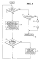
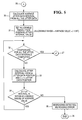
- Fig. 4 and 5 show control flows of the above-described magnetic code reading method according to the present invention.
- the controller determines binary "0" or "1” based on the read waveforms of the analog signals (decoding processing), and sequentially writes the series of binary data into the storage buffer (22).
- jitter e.g. 50% jitter
- the detection position of the jitter bit position
- reading processing is performed (28).
- the average value of intervals of occurrence in the stored positions of occurrence of the jitter waveforms is calculated (30).
- the predetermined allowable range is set from the calculated average value of intervals of occurrence of jitter waveforms (31). Then, the all the jitter intervals are calculated by the method described with reference to Fig. 3 (33). It is determined whether or not each jitter interval is within the allowable range (34). The determination is continued until the comparison for all the jitter intervals is completed (32).
- the reading processing is performed (27), while if the intervals are without the allowable range, the reading error processing (35) is performed, and the magnetic reading routine ends (36).
- the magnetic code reading device in a serial digital signal, detected based on the series of readout magnetic waveforms detected by the magnetic sensor, if jitter repeated at fixed intervals corresponding to the rotational period of the timing disk is detected, magnetic code reading and recognition processing is performed, and necessary transaction processing can be performed without determining that the bankbook or magnetic card cannot be recognized and performing error processing.
Abstract
Description
- The present invention relates to a magnetic code reading device and method of operation thereof, for a magnetic recording medium such as a bankbook issued by a bank or the like or a credit card, and more particularly, to a device for reading magnetic code on a magnetic recording medium where predetermined information is written in correspondence with a timing pulse generated in correspondence with a moving distance of a magnetic head.
- A bankbook of a bank or the like has a stripe-shaped magnetic recording medium for recording magnetic code, encoding the name of bank branch that issued the bankbook, an account number and the like, attached thereto. Further, in a magnetic card such as a credit card, a similar magnetic recording medium for recording magnetic code relating to a card number and the like is provided.
- The bankbook or magnetic card is inserted into a bankbook slot or card slot in an automatic teller machine (hereinafter abbreviated to "ATM") or the like, then magnetic code recorded on the magnetic recording medium is read, and predetermined information is recognized.
- As a method for recording magnetic code onto a magnetic recording medium, a digital recording method is employed, and various modulation methods are employed for modulating binary data in correspondence with existence/absence of magnetization, direction of magnetization or the like. Typical modulation methods are an NRZI (Non Return to Zero Inverted) method, an FM (Frequency Modulation) method, an MFM (Modified FM) method, (2, 7), (1, 7) coding methods and the like.
- Among these modulation methods, the FM method and the coding methods enable self clocking by adding a clock signal to each bit indicative of writing code. In the FM method, for example, in a magnetic head transfer mechanism to move a magnetic head having a magnetic sensor on a surface of the stripe-shaped magnetic recording medium, a timing disk for generating a timing pulse in accordance with a moving distance of the magnetic head is provided, and the timing pulse is used as a clock signal, such that predetermined magnetic code is written onto the magnetic recording medium in synchronization with the rising edge (or falling edge) of the timing pulse.
- The magnetic code written in this manner is detected by the magnetic sensor on the magnetic head moving at an almost constant speed on the surface of the magnetic recording medium by the magnetic head transfer mechanism. Then, a serial digital signal relating to the written predetermined information is reproduced based on a series of detected readout magnetic waveforms.
- In a magnetic head transfer mechanism as shown in Fig. 1, the timing disk, for generating the above-described timing pulse used in writing magnetic code, has a disk shape to rotate in accordance with rotation of a lead screw to move the magnetic head. The disk has a plurality of slits at fixed intervals on its periphery. An optical detection sensor, comprising a pair of light emitting device and pohotoreception device, is attached to a frame of the magnetic head transfer mechanism such that the devices hold the periphery of the disk therebetween. In this manner, one timing pulse is generated by a unit moving distance of the magnetic head.
- However, the ATM or the like is not always installed in a position in an excellent air environment. Further, as the ATM or the like contains a printer for printing the statement of each transaction such as cashing on a rolled paper and cutting the printed paper, paper dust occurs within the cabinet.
- The small particles and dust such as paper dust occasionally enter the slits of the timing disk, to prevent the optical detection sensor from precisely detecting the respective slits of the timing disk rotating with the movement of the magnetic head. Accordingly, the above-described timing pulse waveform used in writing magnetic code cannot be generated by the unit moving distance of the magnetic head, and a magnetic waveform written in this state includes a jitter waveform.
- In a case where a writing magnetic waveform including thus-occurred jitter is read, the waveform representing a binary bit is different from that representing a binary bit indicative of regular "1" or "0", and a "high" or "low" part extended for the timing clock unit period is detected.
- In this case, a magnetic code reading device in an conventional ATM or the like determines that a writing error has occurred and performs uniform error processing. The device determines that the bankbook or magnetic card cannot be recognized and ejects it without performing necessary transaction processing.
- By this operation, it is determined that the magnetic data must be written onto the bankbook or magnetic card again, and the bankbook or magnetic card cannot be used for such operation. Also, it is determined that correction must be performed on the ATM or the like, and it cannot be used.
- The present invention has been made in view of the fact that even though a readout magnetic waveform includes jitter, there is no problem in magnetic code reading and recognition processing in a predetermined case, and provides a magnetic code reading device comprising a magnetic head having a magnetic sensor for writing and reading magnetic code onto/from a magnetic recording medium, a timing disk for generating a timing pulse in correspondence with a moving distance of said magnetic head, and a controller for controlling said magnetic head and said timing pulse, wherein upon reading of magnetic code on the magnetic recording medium where predetermined information is written in correspondence with said timing pulse, if jitter appears at fixed intervals, corresponding to a rotational period of said timing disk, in a series of readout magnetic waveforms detected by said magnetic sensor, said controller recognizes said magnetic code based on said series of readout magnetic waveforms including the jitter, while if jitter not related to the rotational period of said timing disk appears, said controller performs reading error processing.
- Said controller has a storage buffer for temporarily storing a serial digital signal detected based on said series of readout magnetic waveforms detected by said magnetic sensor, and detects existence or absence of jitter repeated at fixed intervals corresponding to the rotational period of said timing disk, in said serial digital signal.
- Further, the present invention provides a method for reading magnetic code on a magnetic recording medium where predetermined information is written in correspondence with a timing pulse generated by a unit moving distance of a magnetic head having a magnetic sensor, comprising: a step of outputting a serial digital signal based on a series of readout magnetic waveforms detected by said magnetic sensor; a step of temporarily storing said serial digital signal into a storage buffer; a step of detecting existence or absence of jitter repeated at fixed intervals corresponding to a rotational period of a timing disk for generating said timing pulse, in said serial digital signal; and a step of, if said jitter repeated at fixed intervals appears, correcting said jitter based on said serial digital signal including said jitter and recognizing said magnetic code, while if jitter asynchronous to the rotational period of said timing disk appears, performing reading error processing.
- Embodiments of the present invention will now be described, by way of example, with reference to the accompanying drawings, in which:
- Fig. 1 is a diagram showing the mechanism in a magnetic code reading device in accordance with the present invention;
- Fig. 2A & 2B are diagrams showing examples of "normal waveform" and "jitter waveform" when magnetic code is written in synchronization with the timing clock signal;
- Fig. 3 is a diagram showing an example of the series of binary data relating to readout signals stored in the storage buffer;
- Fig. 4 is a flowchart showing an example of control flow in the magnetic code reading method in accordance with the present invention; and
- Fig. 5 is a flowchart showing an example of control flow in the magnetic code reading method in accordance with the present invention.
-
- Hereinbelow, the details of magnetic code reading device and reading method according to the present invention will be described with reference to the drawings.
- Fig. 1 shows an example of a mechanism in a magnetic code reading device used in the magnetic code reading device according to the present invention.
- A
bankbook 11, inserted into a bankbook slot of an ATM or the like, is transferred to a predetermined magnetic reading position for recognition of thebankbook 11 itself by internal transfer means (not shown). Generally, a stripe-shapedmagnetic recording medium 12 for recording magnetic code encoding information indicative of the name of a bank branch issued the bankbook, an account number and the like, is attached to the rear side of thebankbook 11. The ATM or the like recognizes thebankbook 11 by writing necessary information onto themagnetic recording medium 12 and reading the written magnetic code later. - As shown in Fig. 1, in the magnetic code reading device such as the ATM, a
magnetic head 2 having amagnetic sensor 1 writes and reads predetermined magnetic code while moving along the stripe-shapedmagnetic recording medium 12 of thebankbook 11. - A DC motor capable of forward and reverse rotations is used as a
motor 3. Atransmission belt 4 for transmitting a rotational driving force is held on the rotation shaft of themotor 3. Thetransmission belt 4 transmits the rotational driving force of themotor 3 to a pulley 5. The pulley 5 is fixed to one end of a rotational shaft of alead screw 7. Theread screw 7 has a helical groove as a male screw on its surface. The magnetic head has a helical groove as a female screw engaging with thelead screw 7. When themotor 3 rotates forward, for example, themagnetic head 2 horizontally moves rightward, and when themotor 3 rotates reversely, themagnetic head 2 horizontally moves leftward. Further, themagnetic head 2 slides on a guide shaft 6 to stabilize its running. - A
timing disk 8 is attached to the other end of the rotational shaft of thelead screw 7. Thetiming disk 8 has slits at fixed intervals in its periphery, and anoptical sensor 9 is provided in a chassis 10 in a position to hold the periphery of the disk. - The
optical sensor 9 comprises a light emitting device and a photoreception device. As light is transmitted through the portion of the slit of thetiming disk 8 but is blocked at a portion where the slit is not formed, theoptical sensor 9 outputs a timing pulse signal in correspondence with rotation of thetiming disk 8 rotating with the lead screw. - Control means (not shown) detects the position of the
magnetic sensor 1 based on the timing pulse outputted from theoptical sensor 9, and writes predetermined magnetic code onto themagnetic recording medium 12 of thebankbook 11, using the timing pulse as a timing clock signal, in synchronization with the timing clock signal. - Fig. 2 shows examples of "normal waveform" and "jitter waveform" when magnetic code is written in synchronization with the timing clock signal.
- Fig. 2(A) shows a case of normal waveform. As described above, the timing clock signal is generated in accordance with the rotation of the
timing disk 8 synchronized with the movement of themagnetic sensor 1. When predetermined magnetic code is written onto themagnetic recording medium 12 of thebankbook 11, in synchronization with the rising edge of the timing clock signal, the writing waveform of data "1" is (a), and that of data "0" is (c). - However, as shown in Fig. 2(B), if a foreign particle is attached to the slit of the
timing disk 8 and the slit blocks light from the light emitting device of theoptical sensor 9, the "low" period of the timing clock signal is lengthened because the slit cannot be detected. In this status, if data "1" is written, the writing waveform of the data is (b), and if data "0" is written, the writing waveform of the data is (d). Accordingly, in this case, the waveforms (b) and (d) are respectively 50% jitter waveforms with respect to the normal writing waveforms (a) and (c). - The bankbook, in which the writing data including the jitter occurred as described above is written onto the
magnetic recording medium 12, is read later. By movement control on the magnetic head by a mechanism similar to that described above (Fig. 1), themagnetic sensor 1 generates a series of analog electric signals by changes in magnetic amount (magnetic flux) recorded on the magnetic recording medium, while running on the magnetic recording medium at a predetermined speed. - Note that in the present embodiment, the magnetic code writing density in the
magnetic recording medium 12 is 210 bits/inch, and thetiming disk 8 has 82 slits. For example, if it is arranged such that data writing onto the magnetic recording medium is completed by rotations of thetiming disk 8 six times, as 1 bit data is written for 2 pulses of the timing clock as shown in Fig. 2, about 246 bit data can be written onto themagnetic recording medium 12. Assuming that one character is represented by 4 bits, information of 60 or more characters can be written onto themagnetic recording medium 12. - A controller in the magnetic code reading device obtains a series of binary data by decoding the analog electric signals sensed by the
magnetic sensor 1, and stores the data into a storage buffer for temporary storage. - Fig. 3 shows an example of the series of binary data stored in the storage buffer.
- In the magnetic code reading method according to the present invention, the controller obtains such serial data by decoding the analog electric signals sensed by the
magnetic sensor 1, and at the same time, stores the positions of occurrence of jitter waveform. Further, when binary decoding conversion on all the data has been completed, the controller calculates an average value of intervals of occurrence in the stored positions of occurrence of jitter waveform. Then, in consideration of a predetermined allowable range from the calculated average value of intervals of occurrence of jitter waveform, the controller determines whether or not all the jitter waveforms appear at intervals synchronized with the rotational period of thetiming disk 8. If the controller determines that all the jitter waves appear at intervals synchronized with the rotational period of thetiming disk 8, the controller performs reading processing, while if the controller determines that the jitter waves do not appear at intervals synchronized with the rotational period of thetiming disk 8, the controller performs error processing to avoid the risk of misreading. - According to the example of Fig. 3, in a case where the positions of occurrence of the 50% jitter correspond to 8th bit, 19th bit, 30th bit, 41th bit, 52th bit and 64th bit of the serial binary signal stored in the storage buffer, the average value of all the jitter intervals is calculated as {(19-8)+(30-19)+(41-30)+(52-41)+(64-52)} ÷ 5 = 11.2 bits. Assuming that the allowable range is (+1/-1) bits, as 10 < 11.2 bits < 12 holds, it can be regarded that the jitter occurred due to a foreign particle or the like attached to the slit of the
timing disk 8. Then reading processing is performed. If the condition is not satisfied, to avoid the risk of misreading, reading error processing is performed. - Fig. 4 and 5 show control flows of the above-described magnetic code reading method according to the present invention.
- When the
magnetic sensor 1 has completed reading of the magnetic recording medium 12 (21), the controller determines binary "0" or "1" based on the read waveforms of the analog signals (decoding processing), and sequentially writes the series of binary data into the storage buffer (22). In the waveforms representing the respective binary data, if jitter (e.g., 50% jitter) is detected, the detection position of the jitter (bit position) is sequentially stored into a jitter storage buffer in the controller (24). If no jitter has been detected, reading processing is performed (28). When the detection positions of all the jitters have been stored into the jitter storage buffer (26), the average value of intervals of occurrence in the stored positions of occurrence of the jitter waveforms is calculated (30). Then, the predetermined allowable range is set from the calculated average value of intervals of occurrence of jitter waveforms (31). Then, the all the jitter intervals are calculated by the method described with reference to Fig. 3 (33). It is determined whether or not each jitter interval is within the allowable range (34). The determination is continued until the comparison for all the jitter intervals is completed (32). - If all the jitter intervals are within the allowable range, the reading processing is performed (27), while if the intervals are without the allowable range, the reading error processing (35) is performed, and the magnetic reading routine ends (36).
- As described above, in the magnetic code reading device according to the present invention, in a serial digital signal, detected based on the series of readout magnetic waveforms detected by the magnetic sensor, if jitter repeated at fixed intervals corresponding to the rotational period of the timing disk is detected, magnetic code reading and recognition processing is performed, and necessary transaction processing can be performed without determining that the bankbook or magnetic card cannot be recognized and performing error processing.
-
- 1
- Magnetic sensor
- 2
- Magnetic head
- 3
- Driving motor
- 4
- Transmission belt
- 5
- Pulley
- 6
- Magnetic head guide shaft
- 7
- Lead screw
- 8
- Timing disk
- 9
- Optical sensor
- 10
- Chassis
- 11
- Bankbook
- 12
- Magnetic recording medium
Claims (8)
- A magnetic code reading device comprising a magnetic head having a magnetic sensor for writing and reading magnetic code onto/from a magnetic recording medium, a timing disk for generating a timing pulse in correspondence with a moving distance of said magnetic head, and a controller for controlling said magnetic head and said timing pulse,
wherein upon reading of magnetic code on the magnetic recording medium where predetermined information is written in correspondence with said timing pulse, if jitter appears at fixed intervals, corresponding to a rotational period of said timing disk, in a series of readout magnetic waveforms detected by said magnetic sensor, said controller recognizes said magnetic code based on said series of readout magnetic waveforms including the jitter, while if jitter not related to the rotational period of said timing disk appears, said controller performs reading error processing. - A magnetic code reading device as claimed in claim 1, wherein said controller has a storage buffer for temporarily storing a serial digital signal detected based on said series of readout magnetic waveforms detected by said magnetic sensor, and detects existence or absence of jitter repeated at fixed intervals corresponding to the rotational period of said timing disk, in said serial digital signal.
- A magnetic code reading device as claimed in claim 2, wherein said readout magnetic waveforms contain approximately 50% or 100% of said jitter with respect to regular writing waveforms.
- A magnetic code reading device as claimed in any preceding claim, wherein a modulation method for writing magnetic code onto said magnetic recording medium is FM modulation.
- A magnetic code reading device as claimed in any preceding claim, wherein said magnetic recording medium is a magnetic stripe recording medium provided on a bankbook or card.
- A method of reading magnetic code on a magnetic recording medium where predetermined information is written in correspondence with a timing pulse generated by a unit moving distance of a magnetic head having a magnetic sensor, comprising:a step of outputting a serial digital signal based on a series of readout magnetic waveforms detected by said magnetic sensor;a step of temporarily storing said serial digital signal into a storage buffer;a step of detecting existence or absence of jitter repeated at fixed intervals corresponding to a rotational period of a timing disk for generating said timing pulse, in said serial digital signal; anda step of, if said jitter repeated at fixed intervals appears, correcting said jitter based on said serial digital signal including said jitter and recognizing said magnetic code, while if jitter asynchronous to the rotational period of said timing disk appears, performing reading error processing.
- A method as claimed in claim 6, wherein said readout magnetic waveforms contain approximately 50% or 100% of said jitter with respect to regular waveforms.
- A method as claimed in claim 6 or claim 7, wherein a modulation method for writing magnetic code onto said magnetic recording medium is FM modulation.
Applications Claiming Priority (2)
| Application Number | Priority Date | Filing Date | Title |
|---|---|---|---|
| JP32312498A JP4210372B2 (en) | 1998-11-13 | 1998-11-13 | Magnetic code reader and magnetic code reading method |
| JP32312498 | 1998-11-13 |
Publications (2)
| Publication Number | Publication Date |
|---|---|
| EP1001361A2 true EP1001361A2 (en) | 2000-05-17 |
| EP1001361A3 EP1001361A3 (en) | 2001-05-30 |
Family
ID=18151362
Family Applications (1)
| Application Number | Title | Priority Date | Filing Date |
|---|---|---|---|
| EP99308891A Withdrawn EP1001361A3 (en) | 1998-11-13 | 1999-11-08 | Magnetic code reading device and method |
Country Status (4)
| Country | Link |
|---|---|
| US (1) | US6561419B1 (en) |
| EP (1) | EP1001361A3 (en) |
| JP (1) | JP4210372B2 (en) |
| CA (1) | CA2289319C (en) |
Families Citing this family (4)
| Publication number | Priority date | Publication date | Assignee | Title |
|---|---|---|---|---|
| US6909562B2 (en) * | 2001-09-13 | 2005-06-21 | Toshiba Tec Kabushiki Kaisha | Control apparatus for magnetic read |
| US7446897B2 (en) * | 2003-04-04 | 2008-11-04 | Axiohm Transaction Solutions, Inc. | Transactional printer with slip processing mechanism |
| US20080288403A1 (en) * | 2007-05-18 | 2008-11-20 | Clay Von Mueller | Pin encryption device security |
| CN102222211B (en) * | 2011-07-06 | 2014-03-05 | 深圳市铭特科技有限公司 | Magcard decoding method and magcard reading device |
Citations (3)
| Publication number | Priority date | Publication date | Assignee | Title |
|---|---|---|---|---|
| US3831009A (en) * | 1973-08-03 | 1974-08-20 | Westinghouse Learning Corp | Timing system for optically scanned documents |
| US3914789A (en) * | 1973-11-19 | 1975-10-21 | Ibm | Manually operated magnetic card encoder |
| US4040097A (en) * | 1975-01-20 | 1977-08-02 | Kabushiki Kaisha Sankyo Seiki Seisakusho | Magnetic card-reader with movable magnetic head |
Family Cites Families (4)
| Publication number | Priority date | Publication date | Assignee | Title |
|---|---|---|---|---|
| US4599510A (en) * | 1984-01-05 | 1986-07-08 | Merlyn Barth | Vibration-minimizing magnetic card reader |
| MY106779A (en) * | 1990-09-07 | 1995-07-31 | Mitsubishi Heavy Ind Ltd | Magnetic recording method and circuit for toll road ticket. |
| US5235166A (en) * | 1991-02-14 | 1993-08-10 | Xtec Incorporated | Data verification method and magnetic media therefor |
| US5770846A (en) * | 1996-02-15 | 1998-06-23 | Mos; Robert | Method and apparatus for securing and authenticating encoded data and documents containing such data |
-
1998
- 1998-11-13 JP JP32312498A patent/JP4210372B2/en not_active Expired - Fee Related
-
1999
- 1999-10-27 US US09/427,649 patent/US6561419B1/en not_active Expired - Fee Related
- 1999-11-08 EP EP99308891A patent/EP1001361A3/en not_active Withdrawn
- 1999-11-10 CA CA002289319A patent/CA2289319C/en not_active Expired - Fee Related
Patent Citations (3)
| Publication number | Priority date | Publication date | Assignee | Title |
|---|---|---|---|---|
| US3831009A (en) * | 1973-08-03 | 1974-08-20 | Westinghouse Learning Corp | Timing system for optically scanned documents |
| US3914789A (en) * | 1973-11-19 | 1975-10-21 | Ibm | Manually operated magnetic card encoder |
| US4040097A (en) * | 1975-01-20 | 1977-08-02 | Kabushiki Kaisha Sankyo Seiki Seisakusho | Magnetic card-reader with movable magnetic head |
Also Published As
| Publication number | Publication date |
|---|---|
| EP1001361A3 (en) | 2001-05-30 |
| US6561419B1 (en) | 2003-05-13 |
| JP4210372B2 (en) | 2009-01-14 |
| CA2289319C (en) | 2002-12-31 |
| CA2289319A1 (en) | 2000-05-13 |
| JP2000149437A (en) | 2000-05-30 |
Similar Documents
| Publication | Publication Date | Title |
|---|---|---|
| US6580581B1 (en) | Recovery of lateral position of a servo system with respect to longitudinal servo bands of a magnetic tape | |
| US3914789A (en) | Manually operated magnetic card encoder | |
| EP0702823B1 (en) | Apparatus and method for distorted track data recovery | |
| EP0890950B1 (en) | Serial bitstream code for timing-based servo | |
| EP0147065A2 (en) | Optical recording medium and recording and reproducing apparatus therefor | |
| EP0380601B1 (en) | Magnetic character reading apparatus | |
| CA2289319C (en) | Magnetic code reading device and magnetic code reading method | |
| AU627127B2 (en) | Self clocking binary data encoding/decoding method | |
| US5485476A (en) | Method and system for error tolerant synchronization character detection in a data storage system | |
| US7035035B2 (en) | Method of and apparatus for correcting data recording position on recording medium | |
| EP0630018B1 (en) | Interblock gap detection in a data storage system | |
| US4023203A (en) | System for compensating a phase difference between magnetic tracks in a magnetic recorded information regenerating apparatus | |
| GB1595334A (en) | Information processing apparatus | |
| US6449114B1 (en) | Magnetic tape apparatus | |
| US5363252A (en) | Method and system for track skew tolerant acquistion burst sequence validation in a data storage system | |
| EP0836186A3 (en) | Data decoding method and device | |
| US6903892B1 (en) | Minimization of tape repositions using multiple read elements per track | |
| EP0346775A1 (en) | Method for modulating a binary data stream | |
| EP0549154A2 (en) | Repetitive pattern detection | |
| GB2272560A (en) | Data dependent coding for preventing copying of credit/ID cards. | |
| EP0952579A2 (en) | Information reproduction apparatus | |
| EP0435255A1 (en) | Magnetic disk apparatus | |
| Hoecker et al. | Handpulled Magnetic Card, Mass Storage System for a Portable Computer | |
| JPH01227266A (en) | Magnetic card recording and reproducing device | |
| Daniels et al. | A high density magnetic tape cartridge storage system |
Legal Events
| Date | Code | Title | Description |
|---|---|---|---|
| PUAI | Public reference made under article 153(3) epc to a published international application that has entered the european phase |
Free format text: ORIGINAL CODE: 0009012 |
|
| AK | Designated contracting states |
Kind code of ref document: A2 Designated state(s): ES |
|
| AX | Request for extension of the european patent |
Free format text: AL;LT;LV;MK;RO;SI |
|
| PUAL | Search report despatched |
Free format text: ORIGINAL CODE: 0009013 |
|
| RIC1 | Information provided on ipc code assigned before grant |
Free format text: 7G 06K 7/08 A, 7G 06K 7/016 B |
|
| AK | Designated contracting states |
Kind code of ref document: A3 Designated state(s): AT BE CH CY DE DK ES FI FR GB GR IE IT LI LU MC NL PT SE |
|
| AX | Request for extension of the european patent |
Free format text: AL;LT;LV;MK;RO;SI |
|
| 17P | Request for examination filed |
Effective date: 20011130 |
|
| AKX | Designation fees paid |
Free format text: ES |
|
| REG | Reference to a national code |
Ref country code: DE Ref legal event code: 8566 |
|
| 17Q | First examination report despatched |
Effective date: 20070425 |
|
| GRAP | Despatch of communication of intention to grant a patent |
Free format text: ORIGINAL CODE: EPIDOSNIGR1 |
|
| STAA | Information on the status of an ep patent application or granted ep patent |
Free format text: STATUS: THE APPLICATION HAS BEEN WITHDRAWN |
|
| 18W | Application withdrawn |
Effective date: 20090130 |