EP1001548A1 - Method of adjusting a multiband mobile telephony transceiver and its corresponding mobile telephone - Google Patents
Method of adjusting a multiband mobile telephony transceiver and its corresponding mobile telephone Download PDFInfo
- Publication number
- EP1001548A1 EP1001548A1 EP99402813A EP99402813A EP1001548A1 EP 1001548 A1 EP1001548 A1 EP 1001548A1 EP 99402813 A EP99402813 A EP 99402813A EP 99402813 A EP99402813 A EP 99402813A EP 1001548 A1 EP1001548 A1 EP 1001548A1
- Authority
- EP
- European Patent Office
- Prior art keywords
- oscillator
- frequency
- mhz
- reception
- transmission
- Prior art date
- Legal status (The legal status is an assumption and is not a legal conclusion. Google has not performed a legal analysis and makes no representation as to the accuracy of the status listed.)
- Withdrawn
Links
Images
Classifications
-
- H—ELECTRICITY
- H04—ELECTRIC COMMUNICATION TECHNIQUE
- H04B—TRANSMISSION
- H04B1/00—Details of transmission systems, not covered by a single one of groups H04B3/00 - H04B13/00; Details of transmission systems not characterised by the medium used for transmission
- H04B1/005—Details of transmission systems, not covered by a single one of groups H04B3/00 - H04B13/00; Details of transmission systems not characterised by the medium used for transmission adapting radio receivers, transmitters andtransceivers for operation on two or more bands, i.e. frequency ranges
- H04B1/0053—Details of transmission systems, not covered by a single one of groups H04B3/00 - H04B13/00; Details of transmission systems not characterised by the medium used for transmission adapting radio receivers, transmitters andtransceivers for operation on two or more bands, i.e. frequency ranges with common antenna for more than one band
- H04B1/006—Details of transmission systems, not covered by a single one of groups H04B3/00 - H04B13/00; Details of transmission systems not characterised by the medium used for transmission adapting radio receivers, transmitters andtransceivers for operation on two or more bands, i.e. frequency ranges with common antenna for more than one band using switches for selecting the desired band
-
- H—ELECTRICITY
- H04—ELECTRIC COMMUNICATION TECHNIQUE
- H04B—TRANSMISSION
- H04B1/00—Details of transmission systems, not covered by a single one of groups H04B3/00 - H04B13/00; Details of transmission systems not characterised by the medium used for transmission
- H04B1/005—Details of transmission systems, not covered by a single one of groups H04B3/00 - H04B13/00; Details of transmission systems not characterised by the medium used for transmission adapting radio receivers, transmitters andtransceivers for operation on two or more bands, i.e. frequency ranges
-
- H—ELECTRICITY
- H04—ELECTRIC COMMUNICATION TECHNIQUE
- H04B—TRANSMISSION
- H04B1/00—Details of transmission systems, not covered by a single one of groups H04B3/00 - H04B13/00; Details of transmission systems not characterised by the medium used for transmission
- H04B1/38—Transceivers, i.e. devices in which transmitter and receiver form a structural unit and in which at least one part is used for functions of transmitting and receiving
- H04B1/40—Circuits
- H04B1/403—Circuits using the same oscillator for generating both the transmitter frequency and the receiver local oscillator frequency
- H04B1/406—Circuits using the same oscillator for generating both the transmitter frequency and the receiver local oscillator frequency with more than one transmission mode, e.g. analog and digital modes
Definitions
- the subject of the present invention is a method for adjusting the operating frequencies of a mobile telephone multiband and a telephone thus obtained. It is mainly usable, in the field of mobile telephony, when it comes to moving from a given frequency band to another given frequency band, the mostly according to another standard for message coding transmitted.
- the object of the invention is to reduce the cost of manufacturing such a multiband phone.
- TDMA Time Division Multiple Access
- FDMA Frequency Division Multiple Access
- CDMA Coded Division Multiple Access
- the invention applies regardless of the mode of transmission from this point of view.
- the devices mentioned are obviously transceivers and must include a transmission chain and a reception chain.
- the base stations often have the same blocks in a fixed position and components as mobile phones since these are manufactured in large series, and are therefore inexpensive. For this reason the invention concerns mobile telephones, whether these telephones are in themselves mobile or not.
- a device makes it possible to separate a reception channel from a transmission channel.
- the transmission channel taking into account frequency agility generally implemented in the processes of mobile telephony, it is common to make a transmitter with three oscillators.
- a first oscillator, output produces a signal at a transmission frequency.
- This signal is also mixed in a mixer with a signal produced by an oscillator producing a signal at a transition frequency.
- the mixer produces a difference signal having a frequency which corresponds to the difference of the transmission frequency and the frequency of transition. This difference signal is then compared to a signal produced by a third intermediate frequency oscillator.
- the intermediate frequency produced by the third oscillator can be the order of 100 MHz and the difference between the transmission frequency and the frequency of transition is of the same order. Then just play on the frequency of transition to cause, from one frame to another or periodically, changes in transmission frequency and respect the required agility.
- the same oscillator at transition frequency is used in the reception channel.
- the signal that it produces is mixed in a receiving mixer with the signal received.
- the receiving mixer then produces a signal whose frequency is roughly in the order of the frequency of the frequency oscillator intermediate so as to allow immediate strip demodulation basic. This limits the number of mixers and the number of demodulations.
- a separation between the frequency band allocated to the transmission and the frequency band allocated to the reception is 10 MHz in the GSM standard, and 20 MHz in the DCS standard and in the standard PCS.
- Given these excursions very significant (which are around 10% of the nominal frequency of the oscillator), it does not appear possible in the current state of the technology of making these oscillators to make them cover two bands, even the two closer (DCS and PCS). Having them cover a single strip is already a problem.
- the spectral purity of these oscillators must be better than -87dBc / Hz at 10 KHz of the carrier, better than -107dBc / Hz at 100 KHz of the carrier and better than -140dBc / Hz at 3 MHz from the carrier.
- the adjustment range of frequency of the oscillator at the transition frequency is theoretically between 1 and 2 GHz.
- the complexity of these oscillators, for GSM, DCS and PCS applications leads to storing them in three categories.
- a first category we list the controlled oscillators in tension and said not adjusted.
- the tension power supply is in the range of three volts. Indeed, they use three elements of battery, that is to say 3.6 volts. A regulator reduces this voltage to three volts available.
- the useful control voltage is then understood between 0.5 and 2.5 volts. Given the catching-up of the dispersion of voltage characteristics, this voltage range cannot be completely exploited, and in practice the frequency band around a frequency of imposed base can only be of the order of 40 MHz.
- These oscillators of first category are also the cheapest.
- the useful band is further increased around a base frequency imposed in two ways. Either we realize a switching of a resonator of the oscillator, or we increase the range of control voltage. Switching an element in the oscillator allows to have a second band. This switched element not being adjusted, it is difficult to achieve high precision. In addition a such an element adds a temperature drift, if it is of great importance in the frequency of the oscillation. For this reason, the frequency hopping is limit. The two bands must remain in a limited band. For a same control voltage range of two volts, thus obtaining a 220 MHz operating range. Comparable results are obtained using a voltage multiplier. The oscillator does not get more complex, but the control circuit is. The oscillators of this third category are obviously much more expensive than those of the second category, which themselves are more expensive than those of the first category.
- a multiband mobile phone should have transceiver systems in as many copies as we would like be able to cover different bands.
- the cost of such a phone mobile telephony would then be directly proportional to the number of bands served. In the general case, its cost would be multiplied by four, especially because we would multiply the oscillators. It's not acceptable.
- this problem will be solved from a limited number oscillators.
- the primary object of the invention is therefore to decrease the number of voltage controlled oscillators and reduce the cost.
- Another object of the invention is, when using oscillators even with a small adjustment range, not having to switch the oscillator at the transition frequency between transmission and reception, then even that the adjustment ranges of these oscillators are small compared to the desired frequency variation dynamics for any standard given. Indeed, we want to be able to exploit all the possibilities of standards which provide, when you want to transmit large amounts of information, to ensure transmission in successive time windows. In in this case, the transmission to reception passages must be carried out for shorter durations. Oscillator switching is unacceptable in this case: the switching time of a high dynamic range oscillator is too long long.
- One of the means of the invention consists in having dividers of frequency at the output of the oscillators, in particular at the output of the oscillator at intermediate frequency and also between a first mixer and a comparator. We then play on the division coefficients of these dividers so as to produce by algebraic composition (by addition or subtraction) frequency combinations allowing the exploration of all allocated bandwidths, in transmission and in reception, limiting by elsewhere the adjustment dynamics of an adjustable oscillator, essentially the transition frequency oscillator.
- the solution of the invention is then remarkable in the sense that one does not not switch the oscillators used when going from emission to reception and reciprocally. As such switching is not present, the rise time to lead to a given use of an oscillator, due frequency agility, leads to being able to use time windows successive, in the same TDMA frame, which is favorable to the increase in information rates to be transmitted with a telephone mobile telephony.
- a radiofrequency synthesizer the frequency oscillator of transition, because of the principle of heterodyne reception (filtering of selectivity on a single intermediate frequency) must follow steps of frequency of the input signal, i.e. stepped channels every 200 KHz. This is not the case with the intermediate frequency oscillator which, especially in GSM, DCS and PCS, can be synthesized from a recommended clock frequency.
- the recommended frequency is 13 MHz, and leads to a step of 1 MHz, obtained by division by 13.
- the intermediate frequency oscillator is faster (in a ratio of the square root of the ratios of the frequencies of comparison: here ⁇ 5) than the transition frequency oscillator, and this for the same loop, and for equivalent spectral purities.
- the operating range of the transition frequency oscillator taking the presence as a criterion dividers, the renunciation of switching the oscillator to the frequency transition, and an infradyne-supradyne composition both in transmission-reception than in different GSM, DCS, and PCS bands.
- the single frequency transition oscillator being third category, while the intermediate frequency oscillator is first category. Either these two oscillators are at most second category. This results in a significant reduction in the price of the transceiver and therefore the multiband telephone.
- TABLE 1 and TABLE 2 are tabulated representations of different setting possibilities oscillators of the invention.
- TABLE 1 and TABLE 2 are incorporated into this description of which it forms a part.
- TABLE 1 and TABLE 2 form an integral part of the description, and as such do not need to be more particularly described.
- FIGS 1 and 2 show a transceiver usable in a mobile telephone according to the invention.
- This transceiver is triband and dual band respectively in these figures.
- This phone can be placed as a transceiver in a base station or a mobile phone since in the end it includes all the organs useful for transmission and reception. This results in considerably lowering the cost of base stations also.
- This mobile phone essentially comprises an antenna 1 and a transmission channel 2. It also includes first, second and third oscillators voltage controlled respectively 3, 4 and 5. These oscillators 3, 4 and 5 carry the designations VCO (for voltage controlled oscillator), TX, RF or FI relating to the nature of the frequency of the signal they produce: transmission, transition (RF) or intermediate frequency.
- VCO for voltage controlled oscillator
- Oscillator 4 has also a TX indication for transmission (and RX for reception) according to the use which is made of it because in the invention, this oscillator 4 is preferably unique and serves both purposes.
- oscillator 3 produces the signal at the transmission frequency which is transmitted by channel 2 to antenna 1.
- channel 2 includes a power amplifier 6 and a diplexer circuit 7.
- a circuit diplexer (by analogy with duplexers) is responsible for separating by filtering of transmission channels according to whether the signal will be in a band (GSM, DCS, PCS) or another.
- This phone also has a first mixer 8 to two starters. On a first input the mixer 8 receives a signal from from oscillator 3 and sampled by a sensor 9. On a second input it receives the output signal from oscillator 4 at the transition frequency.
- FTX the frequency of the signal produced by oscillator 3 to the mixer 8
- RFTX the frequency of the signal produced by oscillator 4.
- the mixer delivers a signal with a frequency fm.
- Comparator 9 outputs a signal control that controls the operation of oscillator 3. With regard to concerns oscillators 4 and 5 they are also controlled by a circuit 11 regulation and programming whose operation will be seen more far.
- a modulator 12 receiving transmission I and Q signals (ITX and QTX). Placing the modulator 12 there is not a need. The modulator 12 could be placed in any other place.
- the telephone of the invention also includes other organs (especially those useful for the production of ITX and QTX signals) not described because common to the invention and to known telephones.
- the telephone of the invention also includes a microprocessor 15 connected by a bus 16 to a memory 17 for program and work.
- Bus 16 also produces control signals for modifying the R and N values on request, to control the adjustment circuit 11, to switch the diplexer 7 as well as controlling in general all useful circuits.
- the numbers R and N may be modified: the dividers 13 and 14 will be programmable by the microprocessor 15. Therefore, according to the multiple bands which we want the mobile phone to of the invention can be adapted, we can choose oscillators 3, 4 and 5 with different frequency ranges, and ordered differently, to limit the total number of oscillators.
- the mobile telephone of the invention also comprises a reception channel 18.
- Channel 18 is connected to antenna 1 by through a transmission reception reception separator 19, called a duplexer, which, alternatively, connects antenna 1 to channel 2 or to channel 18.
- Channel 18 like channel 2 has a diplexer 20. It also has a low noise amplifier 21 in cascade with the diplexer 20.
- Channel 18 of reception is connected to a first input of a second mixer 22.
- the mixer 22 is connected by another input to an output of the second oscillator 4.
- the second oscillator 4 in this case delivers a signal to a transitional RFRX frequency, i.e. at a relatively high frequency close to the frequency of the signal going through the antenna 1. As far as concerns frequency agility, it will be achieved by programming oscillator 4.
- the second oscillator 4 is either assigned to transmission and reception as shown, either assigned to a band or to another band.
- the frequency of the signal received in channel 18 is thus lowered by mixing in the mixer 22.
- the resulting signal is injected, through a filter 24, into a third mixer 25 by a first entry.
- the third mixer 25 receives by another input the signal from the third oscillator 5 via a third divider 26.
- the third divider 26 is only a divider by two.
- FIG. 2 the same elements have been retained as in FIG. 1. However, instead of having two diplexers and a switch 19, there is a diplexer and two switches. The organs 7 and 20 are then filters separated.
- dividers and mixers can be classic.
- the signals are frequency modulated, that they are at constant amplitude, just pass them through a set toggle D to divide their frequency by two, by three, by four etc.
- a pass filter broadband low to find workable signals.
- the comparator 10 may have a low frequency low pass filter, for example example between 10 and 100 KHz, before attacking oscillator 3.
- the mixers are generally of the type imbalance. Preferably, the most favored signal of these two is exploited. signals. For this reason we speak of infradyne mixer and mixer supradyne. To switch from one to the other, simply reverse the entries.
- the mixer 22 will be an infradyne mixer. It provides a mixing signal whose frequency is less than any one of mixed signals.
- the baseband demodulated signal is not directly available at the outlet of the third mixer 25.
- the fourth mixer 27 receives on another input the signal produced by oscillator 5 at frequency intermediate, divided by a fourth divider 29.
- the divisor of the fourth divisor 29 is 12.
- Mixers 25 and 27 are quadrature mixers of even that the modulator 12 is a quadrature modulator. They produce therefore, depending on the case, I and Q signals on reception (IRX and QRX). These signals are then processed in the mobile phone by circuits not shown. These circuits, not shown, were also those which produced the ITX and QTX signals usable for transmission.
- the first oscillator 3 will be connected in parallel with a fourth oscillator 30 between the comparator 10 and the diplexer 7.
- the fourth oscillator 30 will be tuned on a different frequency range than that of the first oscillator 3.
- the fourth oscillator 30 will also be connected to an amplifier power 31 whose output is connected to one of the two inputs of the diplexer 7. If necessary, a sensor 32 takes the signal from oscillator 30 to apply it also to the first input of mixer 8.
- the diplexer 20 has a second output allowing applying the signals received to a fifth mixer 33, supradyne, mounted in parallel with the second mixer 22 in the reception channel 18.
- the parallel channel will also include an amplifier with low noise 34. Filters are also inserted in each channel parallel to the receiver channel 18.
- the division by 2 is due to the presence of the divider 26.
- the inversion signs is due to supradyne-infradyne functioning.
- the inversion of sign is due to the supradyne and infradyne character of the mixtures.
- which is remarkable in the invention is while such an inversion is also used, on transmission, to switch from the GSM band to the DCS band or PCS or other.
- the first line (1 expresses for example that Y - Z, which must be between -25 and +25, results from the theoretical gap 95 between the bands in transmission and reception, compensated by the mixtures with A / 2 and bC.
- the simplest solution for triple band operation comprises a simple first category oscillator for oscillator 5 and a third category for the frequency oscillator of transition.
- the solution according to the invention is therefore to contain the variation of frequency in a band of 220 MHz for the three bands, both in reception than transmission.
- TABLE 1 contains several columns. It also includes groups of indications, separated by empty spaces. Some groupings represent a solution for carrying out the diagram of FIGS. 1 or 2. In each grouping you will find either GSM and DCS, or GSM, DCS and PCS. In the first column, we have indicated, in shorthand, the types of band frequency affected. In a second column we showed the frequencies of signals delivered for reception by the oscillator 4. In a third column we showed the frequencies of the signals delivered for the emission by the oscillator 4. In a fourth column, we indicated the adjustment difference ⁇ between the starting value of the frequency dynamics in emission and the starting value of the frequency dynamic in reception in a given mode.
- oscillator 5 delivers a signal at 540 MHz. In this case we have chosen, for the GSM band, for N the value 3 and for R the value 5. This brings on comparator 10 to receive from the oscillator 5 a signal at a frequency of 540MHz / 5 equal to 108 MHz.
- the oscillator 30 used will have, at the start of the range, a frequency of 880 MHz.
- the mixer 8 then receives a signal at 880 MHz on his first entry.
- the signal delivered by oscillator 4 is then 1204 MHz.
- the difference 1204 MHz minus 880 MHz leads to a signal at 324 MHz.
- N By dividing the frequency of this signal by the coefficient N equal to 3 we also gets 108 MHz.
- the mixer 33 On reception, the mixer 33 will receive a signal at 1195 MHz in from oscillator 4. It will also receive a signal at 925 MHz from antenna 1. The difference of 270 MHz delivered by mixer 33 will be filtered in filter 24 which precisely has a value of 270 MHz.
- oscillator 4 (or as oscillator 23) to provide the signal to transition frequency in transmission and reception.
- this couple 36 of these oscillators will also receive a control signal in from microprocessor 15 to carry out commissioning adequate.
- oscillator 4 must have a dynamic range of 39 MHz.
- a single oscillator 23 will be used but will have a dynamic range of 79 MHz, instead of having a dynamic of 170 MHz as in the state of the art.
- the oscillator 5 will not have the same intermediate frequency value depending on whether it will act in emission and reception.
- the difference between 540 MHz and 537 MHz being very small, on the one hand we are sure to be located with the circuit 11 in the adjustment range of this oscillator 5 and on the other hand, the rallying of the new value will be very rapid.
- the circuit 11 will therefore change the value of oscillator 5 and switch the functionality of oscillators 4 and 23. More precisely the output of a oscillator will be applied to mixer 8 or mixer 33. In this case the other is neutralized. In another range, the other oscillator will be used.
- the third grouping shows an example of realization, not in accordance with the invention, which was practiced in the state of the technical,
- the DCS range also requires a third category oscillator.
- an additional third category oscillator is needed for the PCS range, with no hope that an oscillator serving in a range may serve in another.
- the last four groupings which are shown in TABLE 1 have the particularity that, if they are triband, they require a third category oscillator. They require a second oscillator category if they are dual band. Or for three bands, two oscillators of second category can be used.
- the dynamics of oscillator 4 used in emission or in dual band reception as required will be from 1365 MHz to 1445 MHz. She is at barely higher, with 80 MHz in total, than the dynamic range of 75 MHz of a only transmit or receive bands in the DCS range.
- the fourth group is similar to the fifth group. In the latter, however, the dynamic differences are even smaller: it is even easier to control the frequency oscillators from transition. On the other hand, between the emission and the reception the frequency difference of the intermediate frequency oscillator should be more accentuated, going from 880 to 847 MHz. In both cases, the comparison frequencies, around of 170 MHz and around 121 MHz are external by their harmonics to the bands concerned in emission.
- the number of filters can be reduced by transmission and on the other hand we effectively eliminate parasites from the emission synthesis during the last mixing in the mixer 8.
- GSM Global System for Mobile Communications
- DCS DCS
- PCS PCS
Abstract
Description
La présente invention a pour objet un procédé de réglage des fréquences de fonctionnement d'un téléphone de téléphonie mobile multibande et un téléphone ainsi obtenu. Elle est principalement utilisable, dans le domaine de la téléphonie mobile, quand il s'agit de passer d'une bande de fréquence donnée à une autre bande de fréquence donnée, la plupart du temps selon une autre norme pour le codage de messages transmis. Le but de l'invention est de réduire le coût de fabrication d'un tel téléphone multibande.The subject of the present invention is a method for adjusting the operating frequencies of a mobile telephone multiband and a telephone thus obtained. It is mainly usable, in the field of mobile telephony, when it comes to moving from a given frequency band to another given frequency band, the mostly according to another standard for message coding transmitted. The object of the invention is to reduce the cost of manufacturing such a multiband phone.
Dans le domaine des radiocommunications, on connaít la norme dite GSM dans laquelle des messages sont diffusées par des stations de base et ou des téléphones mobiles dans la gamme des 900MHz. On connaít par ailleurs la norme DCS dans laquelle la gamme de fréquence est de l'ordre de 1800 MHz. Il existe par ailleurs la gamme PCS dans laquelle cette bande de fréquence est de 1900 MHz. Il existe encore la norme UMTS dans laquelle la bande de fréquence est de 2200 MHz. L'existence de toutes ces bandes ou d'autres à venir est bien entendue favorable à la multiplicité des réseaux de communication, et donc à une possibilité en fréquence plus grande, pour des utilisateurs, d'être connectés les uns avec les autres.In the field of radiocommunications, we know the so-called standard GSM in which messages are broadcast by base stations and or mobile phones in the 900MHz range. We know by elsewhere the DCS standard in which the frequency range is of the order of 1800 MHz. There is also the PCS range in which this band of frequency is 1900 MHz. There is still the UMTS standard in which the frequency band is 2200 MHz. The existence of all these bands or others to come is of course favorable to the multiplicity of networks of communication, and therefore at a higher frequency possibility, for users, to be connected with each other.
En plus des bandes de fréquence différentes, il existe des répartitions de canaux de transmission de type temporel, fréquentiel ou par codage, de façon à pouvoir acheminer à partir d'une même station de base, et dans un même domaine géographique, des communications diverses et simultanées. Les transmissions sont ainsi de type TDMA, FDMA ou CDMA ou encore mixte. Les significations de ces appellations sont Time Division Multiple Acces, ou Frequency Division Multiple Access ou Coded Division Multiple Access dont les traductions sont Accès Multiple à Répartition dans le Temps, en Fréquence, ou de Codage, AMRT, AMRF, et AMRC. L'invention s applique quel que soit le mode de transmission de ce point de vue.In addition to the different frequency bands, there are distributions time, frequency or coding type transmission channels, so that you can route from the same base station, and in a same geographic area, various and simultaneous communications. The transmissions are thus of TDMA, FDMA or CDMA type or even mixed. The meanings of these appellations are Time Division Multiple Access, or Frequency Division Multiple Access or Coded Division Multiple Access whose translations are Multiple Access to Time Distribution, Frequency, or Coding, TDMA, TDMA, and CDMA. The invention applies regardless of the mode of transmission from this point of view.
Les appareils évoqués sont évidemment des émetteurs-récepteurs et doivent comporter une chaíne d'émission et une chaíne de réception. Les stations de base comportent souvent en poste fixe des mêmes blocs et composants que des téléphones mobiles puisque ces derniers sont fabriqués en grande série, et sont donc bon marché. Pour cette raison l'invention concerne les téléphones de téléphonie mobile, que ces téléphones soient en eux-mêmes mobiles ou non.The devices mentioned are obviously transceivers and must include a transmission chain and a reception chain. The base stations often have the same blocks in a fixed position and components as mobile phones since these are manufactured in large series, and are therefore inexpensive. For this reason the invention concerns mobile telephones, whether these telephones are in themselves mobile or not.
Dans de tels téléphones, à partir d'une antenne commune, un dispositif permet de séparer une voie de réception d'une voie d'émission. Dans la voie d'émission, compte tenu d'une agilité en fréquence généralement mise en oeuvre dans les procédés de téléphonie mobile, il est courant de réaliser un émetteur avec trois oscillateurs. Un premier oscillateur, de sortie, produit un signal à une fréquence d'émission. Ce signal d'émission est par ailleurs mélangé dans un mélangeur avec un signal produit par un oscillateur produisant un signal à une fréquence de transition. Le mélangeur produit un signal de différence ayant une fréquence qui correspond à la différence de la fréquence d'émission et de la fréquence de transition. Ce signal de différence est alors comparé à un signal produit par un troisième oscillateur à fréquence intermédiaire. Pour fixer les idées, la fréquence intermédiaire produite par le troisième oscillateur peut être de l'ordre de 100 MHz et l'écart entre la fréquence d'émission et la fréquence de transition est du même ordre. Il suffit ensuite de jouer sur la fréquence de transition pour provoquer, d'une trame à l'autre ou périodiquement, des changements de la fréquence d'émission et respecter l'agilité requise.In such phones, from a common antenna, a device makes it possible to separate a reception channel from a transmission channel. In the transmission channel, taking into account frequency agility generally implemented in the processes of mobile telephony, it is common to make a transmitter with three oscillators. A first oscillator, output, produces a signal at a transmission frequency. This signal is also mixed in a mixer with a signal produced by an oscillator producing a signal at a transition frequency. The mixer produces a difference signal having a frequency which corresponds to the difference of the transmission frequency and the frequency of transition. This difference signal is then compared to a signal produced by a third intermediate frequency oscillator. To fix ideas, the intermediate frequency produced by the third oscillator can be the order of 100 MHz and the difference between the transmission frequency and the frequency of transition is of the same order. Then just play on the frequency of transition to cause, from one frame to another or periodically, changes in transmission frequency and respect the required agility.
Les problèmes présentés par ce type de fonctionnement sont multiples. Un d'eux est lié à la grande différence de fréquence qui existe entre les différentes normes. En effet, de la norme GSM à la norme DCS, la fréquence est tout simplement doublée. En outre les excursions en fréquence pour réaliser l'agilité en fréquence, elles-mêmes normalisées, sont assez conséquentes. Ainsi pour la norme GSM, la dynamique de fréquence (en émission ou en réception) est de 35 MHz. Pour les normes DCS et PCS elle est de 75 MHz et de 60 MHz respectivement.The problems presented by this type of operation are multiple. One of them is related to the large frequency difference that exists between the different standards. Indeed, from the GSM standard to the DCS standard, the frequency is simply doubled. In addition excursions in frequency to achieve frequency agility, themselves standardized, are quite substantial. So for the GSM standard, the frequency dynamics (transmission or reception) is 35 MHz. For DCS and PCS standards it is 75 MHz and 60 MHz respectively.
Pour un appareil monobande, par ailleurs, un même oscillateur à fréquence de transition sert dans la voie de réception. Dans ce cas, le signal qu'il produit est mélangé dans un mélangeur de réception avec le signal reçu. Le mélangeur de réception produit alors un signal dont la fréquence est sensiblement de l'ordre de la fréquence de l'oscillateur à fréquence intermédiaire de manière à permettre une démodulation immédiate en bande de base. On limite ainsi le nombre des mélangeurs et le nombre des démodulations.For a single-band device, moreover, the same oscillator at transition frequency is used in the reception channel. In this case, the signal that it produces is mixed in a receiving mixer with the signal received. The receiving mixer then produces a signal whose frequency is roughly in the order of the frequency of the frequency oscillator intermediate so as to allow immediate strip demodulation basic. This limits the number of mixers and the number of demodulations.
A titre indicatif, une séparation entre la bande de fréquence allouée à l'émission et la bande de fréquence allouée à la réception est de 10 MHz dans la norme GSM, et de 20 MHz dans la norme DCS et dans la norme PCS. Ceci conduit en définitive les oscillateurs à fréquence de transition à devoir être capables d'une dynamique respectivement de 80 MHz (35 plus 10 plus 35), de 170 MHz (75 plus 20 plus 75) et 140 MHz (60 plus 20 plus 60) pour ces trois normes respectivement. Compte tenu de ces excursions très significatives (qui sont de l'ordre de 10% de la fréquence nominale de l'oscillateur), il n'apparaít pas possible dans l'état actuel de la technologie de fabrication de ces oscillateurs de leur faire couvrir deux bandes, même les deux plus proches (DCS et PCS). Leur faire couvrir une bande unique est déjà un problème.As an indication, a separation between the frequency band allocated to the transmission and the frequency band allocated to the reception is 10 MHz in the GSM standard, and 20 MHz in the DCS standard and in the standard PCS. This ultimately leads the oscillators with a transition frequency to must be capable of a dynamic range of 80 MHz respectively (35 plus 10 plus 35), 170 MHz (75 plus 20 plus 75) and 140 MHz (60 plus 20 plus 60) for these three standards respectively. Given these excursions very significant (which are around 10% of the nominal frequency of the oscillator), it does not appear possible in the current state of the technology of making these oscillators to make them cover two bands, even the two closer (DCS and PCS). Having them cover a single strip is already a problem.
En effet, pour un service de bonne qualité avec un téléphone mobile, la pureté spectrale de ces oscillateurs doit être meilleure que -87dBc/Hz à 10 KHz de la porteuse, meilleure que -107dBc/Hz à 100 KHz de la porteuse et meilleure que -140dBc/Hz à 3 MHz de la porteuse. La plage de réglage de fréquence de l'oscillateur à la fréquence de transition est théoriquement comprise entre 1 et 2 GHz. Dans les faits, la complexité de ces oscillateurs, pour les applications GSM, DCS et PCS conduit à les ranger en trois catégories.Indeed, for a good quality service with a mobile phone, the spectral purity of these oscillators must be better than -87dBc / Hz at 10 KHz of the carrier, better than -107dBc / Hz at 100 KHz of the carrier and better than -140dBc / Hz at 3 MHz from the carrier. The adjustment range of frequency of the oscillator at the transition frequency is theoretically between 1 and 2 GHz. In fact, the complexity of these oscillators, for GSM, DCS and PCS applications leads to storing them in three categories.
Dans une première catégorie, on recense les oscillateurs commandés en tension et dits non-ajustés. Pour ceux-ci, seule la tension de commande permet de rattraper des dispersions de caractéristiques de leurs composants, et de travailler sur une certaine bande de fréquence autour d'une fréquence de base imposée. Dans les téléphones mobiles, aujourd'hui, la tension d'alimentation est de l'ordre de trois volts. En effet, ils utilisent trois éléments de batterie, soit 3,6 volts en nominal. Un régulateur ramène cette tension à trois volts disponibles. La tension de commande utile est alors comprise entre 0,5 et 2,5 volts. Compte tenu du rattrapage de la dispersion des caractéristiques par la tension, cette plage de tension ne peut être totalement exploitée, et en pratique la bande de fréquence autour d'une fréquence de base imposée ne peut être que de l'ordre de 40 MHz. Ces oscillateurs de première catégorie sont aussi les moins chers.In a first category, we list the controlled oscillators in tension and said not adjusted. For these, only the control voltage makes it possible to make up for dispersions of characteristics of their components, and work on a certain frequency band around a frequency basic imposed. In mobile phones today, the tension power supply is in the range of three volts. Indeed, they use three elements of battery, that is to say 3.6 volts. A regulator reduces this voltage to three volts available. The useful control voltage is then understood between 0.5 and 2.5 volts. Given the catching-up of the dispersion of voltage characteristics, this voltage range cannot be completely exploited, and in practice the frequency band around a frequency of imposed base can only be of the order of 40 MHz. These oscillators of first category are also the cheapest.
Dans une deuxième catégorie, on recense les oscillateurs dits ajustés. Pour ceux-ci, la dispersion des caractéristiques due à leurs composants est rattrapée par des réglages préalables. La tension de commande sert toutefois encore à rattraper des dispersions en température. Dans ce cas, pour une même gamme de tension de commande de 2 volts, ou peut disposer autour d'une fréquence de base imposée d'une plage de fonctionnement de 100 MHz.In a second category, we identify the so-called adjusted oscillators. For these, the dispersion of the characteristics due to their components is caught up with prior adjustments. The control voltage is used however still to make up for temperature dispersions. In that case, for the same control voltage range of 2 volts, or can have around a set base frequency a range of 100 MHz operation.
Dans une troisième catégorie, on augmente encore la bande utile autour d'une fréquence de base imposée de deux manières. Soit on réalise une commutation d'un résonateur de l'oscillateur, soit on augmente la gamme de la tension de commande. La commutation d'un élément dans l'oscillateur permet d'avoir une deuxième bande. Cet élément commuté n'étant pas ajusté, il est difficile d'atteindre une grande précision. En outre un tel élément ajoute une dérive en température, s'il a une grande importance dans la fréquence de l'oscillation. Pour cette raison, le saut de fréquence est limité. Les deux bandes doivent rester dans une bande limitée. Pour une même gamme de tension de commande de deux volts, on obtient ainsi une plage de fonctionnement de 220 MHz. On obtient des résultats comparables en utilisant un multiplicateur de tension. L'oscillateur n'en devient pas plus complexe, mais le circuit de commande lui l'est. Les oscillateurs de cette troisième catégorie sont évidemment bien plus chers que ceux de la deuxième catégorie, qui eux-mêmes sont plus chers que ceux de la première catégorie.In a third category, the useful band is further increased around a base frequency imposed in two ways. Either we realize a switching of a resonator of the oscillator, or we increase the range of control voltage. Switching an element in the oscillator allows to have a second band. This switched element not being adjusted, it is difficult to achieve high precision. In addition a such an element adds a temperature drift, if it is of great importance in the frequency of the oscillation. For this reason, the frequency hopping is limit. The two bands must remain in a limited band. For a same control voltage range of two volts, thus obtaining a 220 MHz operating range. Comparable results are obtained using a voltage multiplier. The oscillator does not get more complex, but the control circuit is. The oscillators of this third category are obviously much more expensive than those of the second category, which themselves are more expensive than those of the first category.
Il existe une quatrième catégorie qui comporte deux oscillateurs dans un même boítier. Elle est assimilable en coût à deux oscillateurs de la deuxième catégorie.There is a fourth category which has two oscillators in the same box. It can be compared in cost to two oscillators of the second category.
Compte tenu de ces contraintes de dynamique en fréquence limitée,
la complexité croissante de ces oscillateurs a un impact direct sur leur coût.
On peut ainsi schématiquement leur attribuer des coûts de valeur 1, 2 et 3
selon leur catégorie. Un autre critère pour apprécier le coût d'un étage
émetteur récepteur serait d'additionner toutes les bandes de fréquence de
tous les oscillateurs impliqués.Given these dynamic constraints in limited frequency,
the increasing complexity of these oscillators has a direct impact on their cost.
We can thus schematically assign them costs of
Un téléphone de téléphonie mobile multibande devrait comporter des systèmes d'émission-reception en autant d'exemplaires qu'on voudrait qu'il soit capable de couvrir de bandes différentes. Le coût d'un tel téléphone de téléphonie mobile serait alors proportionnel directement au nombre de bandes desservies. Dans le cas général, son coût serait multiplié par quatre, notamment parce qu'on multiplierait les oscillateurs. Ce n'est pas acceptable.A multiband mobile phone should have transceiver systems in as many copies as we would like be able to cover different bands. The cost of such a phone mobile telephony would then be directly proportional to the number of bands served. In the general case, its cost would be multiplied by four, especially because we would multiply the oscillators. It's not acceptable.
Selon l'invention ce problème va être résolu à partir d'un nombre limité d'oscillateurs. Dans une version complète, et dans un mode d'utilisation, on ne disposera au total que de cinq voire quatre oscillateurs : c'est à dire même moins que ce qui serait nécessaire pour autoriser des fonctionnements dans deux bandes distinctes. L'objet premier de l'invention est donc de diminuer le nombre d'oscillateurs commandés en tension utilisés, et d'en diminuer le coût.According to the invention this problem will be solved from a limited number oscillators. In a full version, and in a mode of use, will only have a total of five or even four oscillators: i.e. even less than what would be required to authorize operations in two separate bands. The primary object of the invention is therefore to decrease the number of voltage controlled oscillators and reduce the cost.
Un autre objet de l'invention est, lorsqu'on utilise des oscillateurs même avec une plage de réglage faible, de ne pas avoir à commuter l'oscillateur à la fréquence de transition entre l'émission et la réception, alors même que les plages de réglage de ces oscillateurs sont faibles devant la dynamique désirée de variation de fréquence pour une norme quelconque donnée. En effet, on veut pouvoir exploiter toutes les possibilités des normes qui prévoient, lorsqu'on veut transmettre des grandes quantités d'information, d'assurer la transmission dans des fenêtres temporelles successives. Dans ce cas, les passages d'émission à réception doivent s'exécuter pendant des durées plus courtes. La commutation d'oscillateur est rédhibitoire dans ce cas : le temps de commutation d'un oscillateur à grande dynamique est trop long.Another object of the invention is, when using oscillators even with a small adjustment range, not having to switch the oscillator at the transition frequency between transmission and reception, then even that the adjustment ranges of these oscillators are small compared to the desired frequency variation dynamics for any standard given. Indeed, we want to be able to exploit all the possibilities of standards which provide, when you want to transmit large amounts of information, to ensure transmission in successive time windows. In in this case, the transmission to reception passages must be carried out for shorter durations. Oscillator switching is unacceptable in this case: the switching time of a high dynamic range oscillator is too long long.
Aussi dans l'invention, on s'est arrangé pour que la dynamique de commande des oscillateurs à fréquence de transition puisse être faible et ne pas avoir à les commuter. De cette façon les oscillateurs sont moins chers, tout en satisfaisant aux besoins.Also in the invention, we have arranged for the dynamics of Transient frequency oscillator control may be weak and not not have to switch them. That way the oscillators are cheaper, while meeting needs.
Un des moyens de l'invention consiste à disposer des diviseurs de fréquence en sortie des oscillateurs, notamment en sortie de l'oscillateur à fréquence intermédiaire et également entre un premier mélangeur et un comparateur. On joue ensuite sur les coefficients de division de ces diviseurs de façon à produire par composition algébrique (par addition ou soustraction) des combinaisons fréquentielles permettant l'exploration de toutes les largeurs de bande allouées, en émission et en réception, en limitant par ailleurs la dynamique de réglage d'un oscillateur réglable, essentiellement l'oscillateur à fréquence de transition.One of the means of the invention consists in having dividers of frequency at the output of the oscillators, in particular at the output of the oscillator at intermediate frequency and also between a first mixer and a comparator. We then play on the division coefficients of these dividers so as to produce by algebraic composition (by addition or subtraction) frequency combinations allowing the exploration of all allocated bandwidths, in transmission and in reception, limiting by elsewhere the adjustment dynamics of an adjustable oscillator, essentially the transition frequency oscillator.
La solution de l'invention est ensuite remarquable en ce sens qu'on ne commute pas les oscillateurs utilisés quand on passe d'émission à réception et réciproquement. Comme une telle commutation n'est pas présente, le temps de montée pour conduire à une utilisation donnée d'un oscillateur, due à une agilité en fréquence, conduit à pouvoir utiliser des fenêtres temporelles successives, dans une même trame TDMA, ce qui est favorable à l'augmentation des débits d'information à transmettre avec un téléphone de téléphonie mobile.The solution of the invention is then remarkable in the sense that one does not not switch the oscillators used when going from emission to reception and reciprocally. As such switching is not present, the rise time to lead to a given use of an oscillator, due frequency agility, leads to being able to use time windows successive, in the same TDMA frame, which is favorable to the increase in information rates to be transmitted with a telephone mobile telephony.
En effet, un synthétiseur radiofréquence, l'oscillateur à fréquence de transition, à cause du principe de la réception hétérodyne (filtrage de sélectivité sur une fréquence intermédiaire unique) doit suivre des pas de fréquence du signal d'entrée, c'est à dire des canaux étagés tous les 200 KHz. Ce n'est pas le cas de l'oscillateur à fréquence intermédiaire qui, notamment en GSM, DCS et PCS, peut être synthétisé à partir d'une fréquence d'horloge recommandée. La fréquence recommandée est de 13 MHz, et conduit à un pas de 1 MHz, obtenu par division par 13.Indeed, a radiofrequency synthesizer, the frequency oscillator of transition, because of the principle of heterodyne reception (filtering of selectivity on a single intermediate frequency) must follow steps of frequency of the input signal, i.e. stepped channels every 200 KHz. This is not the case with the intermediate frequency oscillator which, especially in GSM, DCS and PCS, can be synthesized from a recommended clock frequency. The recommended frequency is 13 MHz, and leads to a step of 1 MHz, obtained by division by 13.
Du fait de son pas de 1 MHz, et donc de sa fréquence de comparaison de 1 MHz, l'oscillateur à fréquence intermédiaire est plus rapide (dans un rapport de la racine carrée des rapports des fréquences de comparaison : ici √5) que l'oscillateur à fréquence de transition, et ce pour une même boucle, et pour des puretés spectrales équivalentes.Because of its 1 MHz step, and therefore its frequency of 1 MHz comparison, the intermediate frequency oscillator is faster (in a ratio of the square root of the ratios of the frequencies of comparison: here √5) than the transition frequency oscillator, and this for the same loop, and for equivalent spectral purities.
Cette rapidité permet de couper plus longtemps les oscillateurs entre chaque fenêtre temporelle, d'où une consommation moindre. Elle permet aussi d'utiliser plusieurs fenêtres dans une même trame pour la transmission de donnée, conformément aux réquisitions de la norme GSM 05 02.This speed makes it possible to cut the oscillators longer between each time window, resulting in lower consumption. She permits also to use several windows in the same frame for transmission data, in accordance with the requirements of the GSM 05 02 standard.
Dans l'invention, on détermine la gamme de fonctionnement de l'oscillateur à fréquence de transition en retenant comme critère la présence des diviseurs, la renonciation à la commutation de l'oscillateur à la fréquence de transition, et une composition infradyne-supradyne tant en émission-réception qu'en bande différente GSM, DCS, et PCS. On aboutit alors à des solutions peu onéreuses, l'oscillateur à fréquence de transition, unique, étant de troisième catégorie, alors que l'oscillateur à fréquence intermédiaire est de première catégorie. Ou bien ces deux oscillateurs sont au plus de deuxième catégorie. Il en résulte une réduction significative du prix de l'émetteur récepteur et donc du téléphone multibande.In the invention, the operating range of the transition frequency oscillator, taking the presence as a criterion dividers, the renunciation of switching the oscillator to the frequency transition, and an infradyne-supradyne composition both in transmission-reception than in different GSM, DCS, and PCS bands. We then end up with inexpensive solutions, the single frequency transition oscillator being third category, while the intermediate frequency oscillator is first category. Either these two oscillators are at most second category. This results in a significant reduction in the price of the transceiver and therefore the multiband telephone.
L'invention a donc pour objet un procédé de réglage d'un émetteur
récepteur multibande de téléphonie comportant une antenne de
rayonnement, une voie d'émission et une voie de réception reliées à cet
aérien, un premier, un deuxième et un troisième oscillateurs commandés en
tension et délivrant respectivement un signal à une fréquence d'émission, un
signal à une fréquence de transition, et un signal à une fréquence
intermédiaire, le signal à la fréquence d'émission étant transmis par le
premier oscillateur à l'antenne, un premier mélangeur connecté en entrée
aux sorties des premier et deuxième oscillateurs, et recevant de ce premier
oscillateur le signal à la fréquence d'émission et de ce deuxième oscillateur
le signal à la fréquence de transition, un comparateur connecté en entrée à
la sortie du premier mélangeur et à la sortie du troisième oscillateur, et
délivrant en sortie un signal de commande du premier oscillateur, et entre le
premier mélangeur et le comparateur et entre le troisième oscillateur et le
comparateur respectivement un premier et un deuxième diviseur de
fréquence,
caractérisé en ce qu'il comporte les étapes suivantes
- on établit un système d'inéquations qui prend en compte une dynamique limitée en fréquence d'un unique oscillateur à fréquence de transition pour que cet oscillateur couvre toutes les bandes désirées en émission et en réception,
- ce système d'inéquations possédant comme inconnues des plages de fréquence de cet oscillateur à fréquence de transition et de cet oscillateur à fréquence intermédiaire,
- on résout le système d'inéquations en choisissant des valeurs de division des diviseurs de fréquence inférieures à un nombre prédéterminé,
- on règle l'émetteur récepteur avec des solutions des inéquations et en programmant les diviseurs,
- et on fait fonctionner le premier mélangeur en infradyne pour une bande de fréquence et en supradyne pour une autre.
characterized in that it comprises the following stages
- a system of inequalities is established which takes into account a dynamic range limited in frequency of a single oscillator with a transition frequency so that this oscillator covers all the desired bands in transmission and in reception,
- this system of inequalities having, as unknowns, frequency ranges of this transition frequency oscillator and of this intermediate frequency oscillator,
- the system of inequalities is solved by choosing division values of the frequency dividers less than a predetermined number,
- we regulate the transceiver with solutions of inequalities and by programming the dividers,
- and the first mixer is operated in infradyne for one frequency band and in supradyne for another.
L'invention sera mieux comprise à la lecture de la description qui suit et à l'examen de la figure qui l'accompagne. Celles-ci ne sont présentées qu'à titre indicatif et nullement limitatif de l'invention. La figure montre :
- Figures 1 et 2 : des représentations schématiques de circuits d'émission et de réception d'un téléphone de téléphonie mobile selon l'invention, respectivement tribande et bibande ;
- Figure 3 : une représentation d'occupation en fréquence des différentes bandes de fréquence à combiner pour les couvrir avec un même oscillateur.
- Figures 1 and 2: schematic representations of transmission and reception circuits of a mobile telephone according to the invention, triband and dual-band respectively;
- Figure 3: a representation of frequency occupancy of the different frequency bands to be combined to cover them with the same oscillator.
La description comporte également un TABLEAU 1 et un TABLEAU 2 qui sont des représentations tabulées de différentes possibilités de réglage des oscillateurs de l'invention. Les TABLEAU 1 et TABLEAU 2 sont incorporés dans la présente description dont il font partie. Les TABLEAU 1 et TABLEAU 2 font partie intégrante de la description, et à ce titre n'ont pas besoin d'être plus particulièrement décrits.The description also includes a TABLE 1 and a TABLE 2 which are tabulated representations of different setting possibilities oscillators of the invention. TABLE 1 and TABLE 2 are incorporated into this description of which it forms a part. TABLE 1 and TABLE 2 form an integral part of the description, and as such do not need to be more particularly described.
Les figures 1 et 2 montrent un émetteur-récepteur utilisable dans un
téléphone de téléphonie mobile selon l'invention. Cet émetteur récepteur est
respectivement tribande et bibande dans ces figures. Ce téléphone peut être
placé à titre d'organe émetteur-récepteur dans une station de base ou un
téléphone mobile puisqu'en définitive il comporte tous les organes utiles pour
l'émission et la réception. Ceci a pour résultat de considérablement baisser
le coût des stations de base également. Ce téléphone de téléphonie mobile
comporte essentiellement une antenne 1 et une voie d'émission 2. Il
comporte également un premier, un deuxième et un troisième oscillateur
commandé en tension respectivement 3, 4 et 5. Ces oscillateurs 3, 4 et 5
portent des appellations VCO (pour oscillateur commandé en tension), TX,
RF ou FI relatives à la nature de la fréquence du signal qu'ils produisent :
fréquence d'émission, de transition (RF) ou intermédiaire. Ils comportent
également une appellation DCS (ou GSM ou autre) selon la norme à
laquelle, dans un exemple, on les destine. L'oscillateur 4 comporte
également une indication TX pour l'émission (et RX pour la réception) selon
l'usage qui en est fait car dans l'invention, cet oscillateur 4 est de préférence
unique et sert pour les deux fonctions.Figures 1 and 2 show a transceiver usable in a
mobile telephone according to the invention. This transceiver is
triband and dual band respectively in these figures. This phone can be
placed as a transceiver in a base station or a
mobile phone since in the end it includes all the organs useful for
transmission and reception. This results in considerably lowering
the cost of base stations also. This mobile phone
essentially comprises an
En émission, loscillateur 3 produit le signal à la fréquence d'émission
qui est transmis par la voie 2 à l'antenne 1. Dans ce but la voie 2 comporte
un amplificateur de puissance 6 et un circuit diplexeur 7. Un tel circuit
diplexeur (par analogie avec les duplexeurs) est chargé de séparer par
filtrage des voies d'émission selon que le signal sera dans une bande (GSM,
DCS, PCS) ou dans une autre.In transmission,
Ce téléphone comporte encore un premier mélangeur 8 à deux
entrées. Sur une première entrée le mélangeur 8 reçoit un signal provenant
de l'oscillateur 3 et prélevé par un capteur 9. Sur une deuxième entrée il
reçoit le signal de sortie de l'oscillateur 4 à la fréquence de transition. On
appelle FTX la fréquence du signal produit par l'oscillateur 3 à destination du
mélangeur 8 et RFTX la fréquence du signal produit par l'oscillateur 4. Le
mélangeur délivre un signal avec une fréquence fm.This phone also has a
Le signal délivré par le troisième oscillateur, ainsi que le signal à la
fréquence fm délivré par le premier modulateur 8 sont conduits sur les deux
entrées d'un comparateur 9. Le comparateur 9 délivre un signal de
commande qui commande le fonctionnement de l'oscillateur 3. En ce qui
concerne les oscillateurs 4 et 5 ils sont par ailleurs commandés par un circuit
11 de régulation et de programmation dont on verra le fonctionnement plus
loin. On a par ailleurs représenté, en cascade entre le mélangeur 8 et le
comparateur 10, un modulateur 12 recevant des signaux I et Q d'émission
(ITX et QTX). Le fait de placer le modulateur 12 à cet endroit n'est pas une
nécessité. Le modulateur 12 pourrait être placé en tout autre endroit.The signal delivered by the third oscillator, as well as the signal at the
frequency fm delivered by the
Le téléphone de l'invention comporte par ailleurs d'autres organes (notamment ceux utiles à la production des signaux ITX et QTX) non décrits car communs à l'invention et aux téléphones connus.The telephone of the invention also includes other organs (especially those useful for the production of ITX and QTX signals) not described because common to the invention and to known telephones.
Une caractéristique essentielle de l'invention se situe dans le fait que
l'oscillateur 5 est relié au comparateur 6 par l'intermédiaire d'un diviseur 13,
par R, alors que le mélangeur 8 est relié au comparateur 10, en cascade ici
avec le modulateur 12, par un diviseur 14 par N. Les diviseurs 13 et 14
permettent de diviser la fréquence des signaux VCOFITX et fm délivrés
respectivement par l'oscillateur 5 et le mélangeur 8. Le comparateur 10 doit
alors comparer des signaux dont la fréquence est plus faible. La fréquence
des signaux ainsi introduits sur les deux entrées du comparateur 10 est bien
inférieure à celle des signaux VCOFITX et fm. Par ailleurs, le modulateur 12
pourrait être placé dans la liaison entre l'oscillateur 5 et le comparateur 10 si
N = R.An essential characteristic of the invention lies in the fact that
the oscillator 5 is connected to the comparator 6 via a
On montrera à l'aide du TABLEAU 1, parmi toutes les combinaisons
possibles de N et R celles qui peuvent conduire, selon l'invention, d'une part
à une réduction du nombre d'oscillateurs et d'autre part à une limitation de la
dynamique de fréquence de ces oscillateurs commandés en tension. A cette
fin, le téléphone de l'invention comporte par ailleurs un microprocesseur 15
relié par un bus 16 à une mémoire 17 de programme et de travail. Le bus 16
produit par ailleurs des signaux de commande permettant de modifier les
valeurs R et N à la demande, de commander le circuit de réglage 11, de
commuter le diplexeur 7 ainsi que de commander d'une manière générale
tous les circuits utiles. Selon une caractéristique de perfectionnement de
l'invention, les nombres R et N pourront être modifiés : les diviseurs 13 et 14
seront programmables par le microprocesseur 15. De ce fait, selon les
bandes multiples auxquelles on veut que le téléphone de téléphonie mobile
de l'invention puisse s'adapter, on pourra choisir les oscillateurs 3, 4 et 5
avec des gammes de fréquences différentes, et commandées différemment,
afin de limiter le nombre total des oscillateurs.We will show using TABLE 1, among all the combinations
possible of N and R those which can lead, according to the invention, on the one hand
a reduction in the number of oscillators and on the other hand a limitation of the
frequency dynamics of these voltage controlled oscillators. At this
end, the telephone of the invention also includes a
Le téléphone de téléphonie mobile de l'invention comporte par ailleurs
une voie de réception 18. La voie 18 est reliée à l'antenne 1 par
l'intermédiaire d'un dispositif séparateur émission réception 19, dit duplexeur,
qui, alternativement, relie l'antenne 1 à la voie 2 ou à la voie 18. La voie 18
comporte comme la voie 2 un diplexeur 20. Elle comporte de plus un
amplificateur faible bruit 21 en cascade avec le diplexeur 20. La voie 18 de
réception est reliée à une première entrée d'un deuxième mélangeur 22. Le
mélangeur 22 est connecté par une autre entrée à une sortie du deuxième
oscillateur 4. Le deuxième oscillateur 4 délivre dans ce cas un signal à une
fréquence RFRX de transition, c'est à dire à une fréquence relativement
proche de la fréquence du signal qui passe par l'antenne 1. En ce qui
concerne l'agilité en fréquence, elle sera réalisée par la programmation de
l'oscillateur 4. Comme on le verra plus loin, le deuxième oscillateur 4 est soit
attribué à l'émission et à la réception comme montré, soit attribué à une
bande ou à une autre bande. La fréquence du signal reçu dans la voie 18 est
ainsi abaissée par mélange dans le mélangeur 22. Le signal résultant est
injecté, au travers d'un filtre 24, dans un troisième mélangeur 25 par une
première entrée. Le troisième mélangeur 25 reçoit par une autre entrée le
signal du troisième oscillateur 5 par l'intermédiaire d'un troisième diviseur 26.
Dans un exemple préféré le troisième diviseur 26 est uniquement un diviseur
par deux.The mobile telephone of the invention also comprises
a
Sur la figure 2, on a retenu les mêmes éléments que sur la figure 1.
Toutefois, au lieu d'y avoir deux diplexeurs et un commutateur 19, on a un
diplexeur et deux commutateurs. Les organes 7 et 20 sont alors des filtres
séparés. In FIG. 2, the same elements have been retained as in FIG. 1.
However, instead of having two diplexers and a
Avec l'organisation ainsi retenue, on peut écrire que
La technologie des diviseurs et des mélangeurs peut être classique.
Pour les diviseurs, étant donné que les signaux sont modulés en fréquence,
qu'ils sont à amplitude constante, il suffit de les faire passer à travers un jeu
de bascule D pour diviser leur fréquence par deux, par trois, par quatre etc.
Pour rétablir un signal sinusoïdal, il suffit de filtrer ensuite par un filtre passe
bas à bande large pour retrouver des signaux exploitables. Dans la pratique,
à la sortie des diviseurs 13 et 14 il n'y aura même pas un tel filtre, seul le
comparateur 10 pourra posséder un filtre passe bas à basse fréquence, par
exemple entre 10 et 100 KHz, avant d'attaquer l'oscillateur 3.The technology of dividers and mixers can be classic.
For the dividers, since the signals are frequency modulated,
that they are at constant amplitude, just pass them through a set
toggle D to divide their frequency by two, by three, by four etc.
To re-establish a sinusoidal signal, it is sufficient to then filter by a pass filter
broadband low to find workable signals. In practice,
at the output of the
En ce qui concerne les mélangeurs ceux-ci sont en général de type
déséquilibré. De préférence on exploite le signal le plus favorisé de ces deux
signaux. Pour celle raison on parle de mélangeur infradyne et de mélangeur
supradyne. Pour passer de l'un à l'autre il suffit d'inverser les entrées. Dans
un exemple, le mélangeur 22 sera un mélangeur infradyne. Il fournit un
signal de mélange dont la fréquence est inférieure à l'un quelconque des
signaux mélangés.As regards the mixers, these are generally of the type
imbalance. Preferably, the most favored signal of these two is exploited.
signals. For this reason we speak of infradyne mixer and mixer
supradyne. To switch from one to the other, simply reverse the entries. In
an example, the
Dans une variante, le signal démodulé en bande de base n'est pas
directement disponible à la sortie du troisième mélangeur 25. Dans ce cas on
peut utiliser un quatrième mélangeur 27 monté en cascade, après un filtre
28, avec le troisième mélangeur 25. Le quatrième mélangeur 27 reçoit sur
une autre entrée le signal produit par l'oscillateur 5 à fréquence
intermédiaire, divisé par un quatrième diviseur 29. Dans un exemple préféré
le coefficient de division du quatrième diviseur 29 vaut 12.Alternatively, the baseband demodulated signal is not
directly available at the outlet of the
Les mélangeurs 25 et 27 sont des mélangeurs en quadrature de
même que le modulateur 12 est un modulateur en quadrature. Ils produisent
donc, selon le cas, des signaux I et Q en réception (IRX et QRX). Ces
signaux sont ensuite traités dans le téléphone de téléphonie mobile par des
circuits non représentés. Ces circuits non représentés étaient par ailleurs
ceux qui produisaient les signaux ITX et QTX utilisables pour l'émission.
Dans une variante simple, il n'y aura qu'un seul oscillateur 3 comme il
n'y aura qu'un seul mélangeur 22 pour effectuer l'émission et la réception
dans deux bandes. Dans un cas préféré cependant, le premier oscillateur 3
sera connecté en parallèle d'un quatrième oscillateur 30 entre le
comparateur 10 et le diplexeur 7. Le quatrième oscillateur 30 sera accordé
sur une autre gamme de fréquence que celle du premier oscillateur 3. Le
quatrième oscillateur 30 sera lui également relié à un amplificateur de
puissance 31 dont la sortie est connectée à une des deux entrées du
diplexeur 7. Le cas échéant un capteur 32 prélève le signal de l'oscillateur 30
pour l'appliquer aussi à la première entrée du mélangeur 8. Dans la voie de
réception, le diplexeur 20 possède une deuxième sortie permettant
d'appliquer les signaux reçus à un cinquième mélangeur 33, supradyne,
monté en parallèle avec le deuxième mélangeur 22 dans la voie de réception
18. Dans ce cas la voie en parallèle comportera aussi un amplificateur à
faible bruit 34. Des filtres sont par ailleurs interposés dans chacune des voies
en parallèles de la voie de récepteur 18.In a simple variant, there will be only one
On va maintenant expliquer comment sont obtenues les valeurs de
fréquence retenues pour l'oscillateur 4 à fréquence de transition et pour
l'oscillateur 5 à fréquence intermédiaire. On va dans un premier temps
désigner par des noms de variable les valeurs de fréquences apparaissant
aux différents noeuds du circuit. Dans un deuxième temps on établira les
inéquations qui résultent des contraintes rappelées ci-dessus de plage
limitée d'un unique oscillateur à fréquence de transition, de non commutation
de cet oscillateur, et de combinaison supradyne-infradyne. Dans un
troisième temps on montrera comment résoudre le système d'inéquations
écrit.We will now explain how the values of
frequency used for
Soient pour les variables :
- IFRX la fréquence du signal disponible en sortie du mélangeur 22,
- FGR la fréquence du signal radioélectrique reçu en GSM,
- FDR la fréquence du signal radioélectrique reçu en DCS,
- FGT la fréquence du signal radioélectrique émis en GSM,
- FDT la fréquence du signal radioélectrique émis en DCS,
- OLGR=W la fréquence de l'oscillateur à fréquence de transition en réception an GSM,
- OLDR=Y la fréquence de l'oscillateur à fréquence de transition en réception an DCS,
- OLGT=X la fréquence de l'oscillateur à fréquence de transition an émission en GSM,
- OLDT=Z la fréquence de l'oscillateur à fréquence de transition en émission an DCS,
- REFRX=A la fréquence de l'oscillateur à fréquence intermédiaire en réception,
- REFGT=B la fréquence de l'oscillateur à fréquence intermédiaire an émission an GSM,
- REFDT=C la fréquence de l'oscillateur à fréquence intermédiaire en émission en DCS.
- IFRX the frequency of the signal available at the output of
mixer 22, - FGR the frequency of the radio signal received in GSM,
- FDR the frequency of the radio signal received in DCS,
- FGT the frequency of the radio signal emitted in GSM,
- FDT the frequency of the radio signal emitted in DCS,
- OLGR = W the frequency of the oscillator with frequency of transition in reception in GSM,
- OLDR = Y the frequency of the oscillator with transition frequency in reception in DCS,
- OLGT = X the frequency of the transmission frequency oscillator on GSM transmission,
- OLDT = Z the frequency of the oscillator with transition frequency in transmission in DCS,
- REFRX = At the frequency of the intermediate frequency oscillator on reception,
- REFGT = B the frequency of the intermediate frequency oscillator on transmission in GSM,
- REFDT = C the frequency of the intermediate frequency oscillator in DCS transmission.
Cas signaux sont par ailleurs indiqués sur les figures 1 et 2, sur les connexions sur lesquels ils sont disponibles.Signal cases are also indicated in Figures 1 and 2, on the connections on which they are available.
En réception, on peut écrire les deux équations suivantes :
- en GSM
- IFRX = REFRX / 2 = OLGR -FGR
- en DCS
- IFRX = REFRX / 2 = -OLDR+FDR
- in GSM
- IFRX = REFRX / 2 = OLGR -FGR
- in DCS
- IFRX = REFRX / 2 = -OLDR + FDR
La division par 2 est due à la présence du diviseur 26. L'interversion
des signes est due au fonctionnement supradyne-infradyne.The division by 2 is due to the presence of the
En émission, on peut écrire les deux équations suivantes :
- en GSM
- FGT = OLGT - (N/R) REFGT
- an DCS
- FDT = OLDT + (N'/R') REFDT
- in GSM
- FGT = OLGT - (N / R) REFGT
- year DCS
- FDT = OLDT + (N '/ R') REFDT
Dans l'invention, en effet, dans les deux cas ci-dessus, l'inversion de signe est du au caractère supradyne et infradyne des mélanges. Ce qui est remarquable dans l'invention est alors qu'une telle inversion est aussi pratiquée, an émission, pour passer de la bande GSM à la bande DCS ou PCS ou autre.In the invention, in fact, in the two cases above, the inversion of sign is due to the supradyne and infradyne character of the mixtures. Which is remarkable in the invention is while such an inversion is also used, on transmission, to switch from the GSM band to the DCS band or PCS or other.
De ces équations il ressort les fréquences suivantes de l'oscillateur à
fréquence de transition :
Avec les variables A, B, C, W, X, Y, et Z, et en retenant a = N / R et b = N' / R', on obtient, pour les milieux des bandes normalisées en GSM et DCS, les équationsWith the variables A, B, C, W, X, Y, and Z, and retaining a = N / R and b = N '/ R', one obtains, for the mediums of the bands standardized in GSM and DCS, the equations
Suivant la catégorie d'oscillateur décrit plus haut, la solution selon
l'invention la plus intéressante conduit, pour un émetteur récepteur bibande,
à un oscillateur unique, de première catégorie (la moins chère), pour
l'oscillateur 5. Et, il faut un oscillateur ajusté, de deuxième catégorie, pour
l'oscillateur 4. En effet celui-ci doit couvrir, selon les équations eq-I,
La contrainte d'une plage de réglage inférieure à 100 MHz pour
l'oscillateur 4 est réalisée en choisissant pour milieu de la plage de réglage
en émission, Z, une fréquence suffisamment peu différente du milieu de la
plage de réglage en réception Y. Cette différence doit alors être telle que la
somme de celle différence augmentée de 37,5 MHz vers les valeurs basses
et de 37,5 MHz vers les valeurs hautes soit inférieure à 100 MHz. La figure 3
montre, dans le cas où Y est plus grand que Z comment s'exprime celle
contrainte. Dans ce cas, la plage 40, en émission, centrée sur Z est décalée
de |Y - Z| de la plage 41 en réception centrée sur Y. Le total des deux
plages, en recouvrement ne doit pas dépasser la limite choisie (100 MHz
dans le cas montré). Ceci s'écrit
De même en GSM on obtiendra
Si on veut une combinaison entre GSM et DCS, on sera conduit à
La contrainte sur l'oscillateur à fréquence intermédiaire conduit avec
un même raisonnement à
On obtient ainsi 9 double inéquations, eq-II, qu'on peut résoudre on A,
B, C, en tenant compte des équations eq-I. Les inéquation eq-II sont par
ailleurs simplifiées sous une forme eq-III :
La première ligne (1 exprime par exemple que Y - Z, qui doit être compris entre -25 et +25, résulte de l'écart théorique 95 entre les milieux des bandes en émission et en réception, compensé par les mélanges avec A / 2 et bC.The first line (1 expresses for example that Y - Z, which must be between -25 and +25, results from the theoretical gap 95 between the bands in transmission and reception, compensated by the mixtures with A / 2 and bC.
Si on additionne les deux inéquations (1 et (3 :
Si on additionne les deux inéquations (2 et (6 :
Par ailleurs, l'inéquation 4 conduit à
Les inéquations à traiter deviennent alors
Si 855 < A < 945 et |B - A| et |C - A| < 30, alors A et B doivent être
compris entre 825 et 975 MHz. Ceci limite les valeurs de a et b. En prenant
N, N', R et R' inférieurs à 8, la condition (1 conduit à 920/975 < b < 390/825,
soit b = 1/3, 3/8, 2/5, 3/7. En faisant de même avec la condition 3, on limite a
à 460/975 < a < 550/825, soit a = 1/2, 4/7, 3/5, 5/8, 2/3. Le tableau,
TABLEAU 2, suivant donne alors pour les valeurs de a et b trouvées les
solutions des différentes inéquations.If 855 <A <945 and | B - A | and | C - A | <30, then A and B must be
between 825 and 975 MHz. This limits the values of a and b. Taking
N, N ', R and R' less than 8, the condition (1 leads to 920/975 <b <390/825,
let b = 1/3, 3/8, 2/5, 3/7. By doing the same with
On en déduit plusieurs groupement de valeurs donnant des solutions simples et peu coûteuses pour réaliser un téléphone bibande.We deduce several groupings of values giving solutions simple and inexpensive to make a dual band phone.
Pour un fonctionnement en triple bande, la solution la plus simple selon l'invention comporte un oscillateur simple de première catégorie pour l'oscillateur 5 et un de troisième catégorie pour l'oscillateur à fréquence de transition. En effet, compte tenu de la configuration de réception, des largeurs de bande DCS et PCS, et de leur écart, la bande totale DCS PCS en réception est contenue dans 1990 - 1805 = 185 MHz. Soit une bande supérieure à celle d'un oscillateur de deuxième catégorie.The simplest solution for triple band operation according to the invention comprises a simple first category oscillator for oscillator 5 and a third category for the frequency oscillator of transition. In fact, taking into account the reception configuration, DCS and PCS bandwidths, and their deviation, the total DCS PCS band in reception is contained in 1990 - 1805 = 185 MHz. Either a band greater than that of a second category oscillator.
Aussi la solution selon l'invention est-elle de contenir la variation de fréquence dans une bande de 220 MHz pour les trois bandes, tant en réception qu'en émission. Dans ce cas on contiendra la variation de fréquence de l'oscillateur à fréquence de transition, sur tous les canaux PCS à un maximum de 100 MHz.The solution according to the invention is therefore to contain the variation of frequency in a band of 220 MHz for the three bands, both in reception than transmission. In this case we will contain the variation of oscillator frequency at transition frequency, on all PCS channels at a maximum of 100 MHz.
On réécrit alors les inéquations comme précédemment eq-II et eq-III
en prenant U et V comme milieux de bande de réception et d'émission de
l'oscillateur 4 quand il est dans la gamme PCS. On obtient U = 196 - A / 2 et
V = 1880 - cD. Avec D la valeur de fréquence de l'oscillateur à fréquence
intermédiaire en émission, et c le rapport N''/R'' des coefficients diviseurs
retenus pour cette gamme PCS.We then rewrite the inequalities as previously eq-II and eq-III
taking U and V as the receiving and transmitting band media of
La contrainte d'une bande inférieure à 100 MHz conduit à
La contrainte d'une bande de 220 MHz, par rapport à la bande GSM
conduit à
La contrainte d'une bande de 220 MHz par rapport à une bande DCS
conduit à
La contrainte d'une bande de l'oscillateur à fréquence intermédiaire toujours inférieure ou égale à 30 MHz conduit à |D - A| < 30, |D - B| < 30, et à |D - C| < 30.The constraint of a band of the intermediate frequency oscillator always less than or equal to 30 MHz leads to | D - A | <30, | D - B | <30, and to | D - C | <30.
Les contraintes sur U - Y et U - W portant sur les différences en
réception, peuvent être oubliées. En effet
De même pour |U - X| < 172,5 qui implique que
De même enfin que |U - Z| < 152,5 implique que
Les inéquation eq-III peuvent s'écrire
Ces cinq inéquations sont respectivement équivalentes à
Elles se combinent avec -30 < |D - A| < 30, -30 < |D - B| < 30, et -30 <|D - C| < 30. Ces inéquations conduisent àThey combine with -30 <| D - A | <30, -30 <| D - B | <30, and -30 <| D - C | <30. These inequalities lead to
De la comparaison des inéquations eq-III et eq-IV, on peut remarquer que si bC + 5 < cD < bC + 30, les équations IV-1 à IV-4 sont vérifiées.From the comparison of the inequalities eq-III and eq-IV, we can notice that if bC + 5 <cD <bC + 30, equations IV-1 to IV-4 are verified.
Des inéquation eq-IV-1 et eq-IV-3 on peut tirer
On en déduit le tableau TABLEAU 2We deduce the table TABLE 2
Les conditions nécessaires s'écriventThe necessary conditions are written
En remplaçant dans les inéquations eq-V-1 à eq-V-4 les valeur min et
max de A / 2, bC , aB, on obtient
Au total il reste 325 < cD < 432,5 et 825 < D < 675. Ce qui conduit pour c aux conditions 225/975 < c < 432,5/825, soit 1/3 < c < 0,44. Si N'' et R'' sont limités par 8, on peut prendre les mêmes valeurs que b, à savoir 1/3, 3/8, 2/5, 3/7.In total there remain 325 <cD <432.5 and 825 <D <675. Which leads for c under conditions 225/975 <c <432.5 / 825, i.e. 1/3 <c <0.44. If N '' and R '' are limited by 8, we can take the same values as b, namely 1/3, 3/8, 2/5, 3/7.
On va expliquer maintenant à l'aider du TABLEAU 1 le fonctionnement
du téléphone de téléphonie mobile de l'invention. Ce TABLEAU 1 comporte
plusieurs colonnes. Il comporte aussi des groupements d'indications,
séparés par des interlignes vides. Certains groupements représentent une
solution de réalisation du schéma des figures 1 ou 2. Dans chaque
groupement on trouvera ainsi soit GSM et DCS, soit GSM, DCS et PCS.
Dans une première colonne on a indiqué, en raccourci, les types de bande
de fréquence concernés. Dans une deuxième colonne on a montré les
fréquences des signaux délivrés pour la réception par l'oscillateur 4. Dans
une troisième colonne on a montré les fréquences des signaux délivrés pour
l'émission par l'oscillateur 4. Dans une quatrième colonne, on a indiqué
l'écart ▵ de réglage entre la valeur de départ de la dynamique de fréquence
en émission et la valeur de départ de la dynamique de fréquence en
réception selon un mode donné.We will now explain using TABLE 1 how it works
of the mobile telephone of the invention. This TABLE 1 contains
several columns. It also includes groups of indications,
separated by empty spaces. Some groupings represent a
solution for carrying out the diagram of FIGS. 1 or 2. In each
grouping you will find either GSM and DCS, or GSM, DCS and PCS.
In the first column, we have indicated, in shorthand, the types of band
frequency affected. In a second column we showed the
frequencies of signals delivered for reception by the
Dans une cinquième cotonne on a indiqué, pour un usage bibande,
l'exploration maximale de l'oscillateur 4 unique. Selon sa valeur, inférieure à
40 MHz, à 100 MHz, ou à 220 MHz, on en déduit le type d'oscillateur à
retenir. Dans une sixième colonne, on a montré les mêmes éléments pour un
montage tribande. Dans une septième colonne, des commentaires précisent
les catégories des oscillateurs ainsi retenus.In a fifth cotton fabric, for dual band use,
maximum exploration of the
Dans une huitième colonne, on a indiqué la fréquence en réception du troisième oscillateur 5 à fréquence intermédiaire quand il sert en réception. Dans une neuvième colonne et une dixième colonne on a indiqué les valeurs des coefficients de division N et R retenus. Dans une onzième colonne on a indiqué les fréquences de l'oscillateur 5 à fréquence intermédiaire quand il sert en émission.In an eighth column, the frequency on reception of the third intermediate frequency oscillator 5 when used for reception. In a ninth column and a tenth column we indicated the values division coefficients N and R used. In an eleventh column we have indicated the frequencies of oscillator 5 at intermediate frequency when it is used for transmission.
Dans une douzième colonne, on a indiqué le saut en fréquence de l'oscillateur à fréquence intermédiaire quand il sert en émission ou en réception. On constate que ce saut de fréquence impose la catégorie de l'oscillateur à retenir.In a twelfth column, the frequency jump of the intermediate frequency oscillator when it is used for transmission or reception. It can be seen that this frequency hopping imposes the category of the oscillator to remember.
Dans une treizième colonne, on a indiqué par moins ou par plus
l'utilisation d'un mélangeur infradyne 22 ou supradyne 33. Dans la
quatorzième colonne on a indiqué la valeur du premier filtre à fréquence
intermédiaire 24. La quinzième colonne renseigne sur la fréquence de
comparaison fc mise en oeuvre dans le comparateur 10. En bas du
TABLEAU 1 on a rappelé les gammes normalisées des bandes GSM, DCS
et PCS, en émission, en réception, ainsi que l'écart normal entre les plages
d'émission et de réception.In a thirteenth column, we indicated by minus or by more
the use of an
Pour le premier groupement représenté, il s'agit des normes GSM et
DCS seulement. Un des deux oscillateurs (par exemple l'oscillateur 4) servira
pour la gamme GSM (mais en émission et en réception), alors qu'un autre
(un oscillateur 23 en parallèle de l'oscillateur 4) servira pour la gamme DCS
(en émission et en réception lui aussi). On se rend compte que l'écart pour
les oscillateurs 23 et 4 entre les plages d'émission et de réception est
seulement de 9 MHz ou de 4 MHz. En effet la dynamique de réception passe
de 1195 à 1230 alors qu'en émission elle passe de 1204 à 1239. En pratique
la dynamique totale de l'oscillateur concerné sera de 44 (35 plus 9) alors
qu'elle était de 80 dans l'état de la technique. En conséquence le réglage
pourra être plus précis. Pour ce premier groupement, l'oscillateur 5 délivre un
signal à 540 MHz. Dans ce cas on a retenu, pour la bande GSM, pour N la
valeur 3 et pour R la valeur 5. Ceci amène en émission, le comparateur 10 à
recevoir en provenance de l'oscillateur 5 un signal à une fréquence de
540MHz / 5 égale à 108 MHz.For the first group represented, these are GSM standards and
DCS only. One of the two oscillators (for example oscillator 4) will be used
for the GSM range (but in transmission and reception), while another
(an
En émission, l'oscillateur 30 utilisé aura, en début de gamme, une
fréquence de 880 MHz. Le mélangeur 8 reçoit alors un signal à 880 MHz sur
sa première entrée. Le signal délivré par l'oscillateur 4 est alors de 1204
MHz. La différence 1204 MHz moins 880 MHz conduit à un signal à 324
MHz. En divisant la fréquence de ce signal par le coefficient N égal à 3 on
obtient également 108 MHz.In transmission, the
En réception, le mélangeur 33 recevra un signal à 1195 MHz en
provenance de l'oscillateur 4. Il recevra par ailleurs un signal à 925 MHz de
l'antenne 1. La différence de 270 MHz délivrée par le mélangeur 33 sera
filtrée dans le filtre 24 qui a justement une valeur de 270MHz.On reception, the
On peut refaire des mêmes calculs, pour ce groupement, avec les
valeurs indiquées pour la gamme DCS. En émission, 1710 MHz moins 1531
MHz égale 179 MHz. Divisé par deux pour le coefficient N du diviseur 14, on
obtient une fréquence de comparaison de 89,5 MHz. Cette fréquence de
comparaison est la même que celle qu'on obtient en divisant par 6 la
fréquence de l'oscillateur 5 à fréquence intermédiaire à 537 MHz.We can redo the same calculations, for this grouping, with the
values indicated for the DCS range. In transmission, 1710 MHz minus 1531
MHz equals 179 MHz. Divided by two for the coefficient N of the
Ces considérations appellent plusieurs remarques. Premièrement un
peu différemment de ce qui a été évoqué, un couple 36 d'oscillateurs de
transition, mais chacun à dynamique plus faible, va servir en tant
qu'oscillateur 4 (ou en tant qu'oscillateur 23) pour fournir le signal à
fréquence de transition en émission et en réception. Dans ce cas, ce couple
36 de ces oscillateurs recevra également un signal de commande en
provenance du microprocesseur 15 pour effectuer les mises en service
adéquates. Dans cette solution, l'oscillateur 4 devra avoir une dynamique de
39 MHz. Par comparaison, pour la gamme DCS, un seul oscillateur 23 sera
utilisé mais aura une dynamique de 79 MHz, au lieu d'avoir une dynamique
de 170 MHz comme dans l'état de la technique. D'autre part, l'oscillateur 5
ne possédera pas une même valeur de fréquence intermédiaire selon qu'il
agira en émission et en réception. Cependant dans le cas DCS, on constate
que l'écart entre 540 MHz et 537 MHz étant très faible, d'une part on est sûr
de se situer avec le circuit 11 dans la plage de réglage de cet oscillateur 5 et
d'autre part le ralliement de la nouvelle valeur sera très rapide. Au moment
de la commutation, au passage d'émission à réception ou réciproquement, le
circuit 11 va donc faire changer la valeur de l'oscillateur 5 et commuter les
fonctionnalités des oscillateurs 4 et 23. Plus exactement la sortie d'un
oscillateur sera appliquée au mélangeur 8 ou au mélangeur 33. Dans ce cas
l'autre est neutralisé. Dans une autre gamme, c'est l'autre oscillateur qui sera
utilisé. These considerations call for several remarks. First a
little differently from what was mentioned, a
On constate dans ce cas qu'on utilise cinq oscillateurs, les oscillateurs
3, 4, 5, 23 et 30. On n'en utilise donc pas six comme on pouvait s'y attendre
compte tenu de l'écart important situé entre la gamme GSM et la gamme
DCS. Dans les autres groupements, il n'y aura que quatre oscillateurs, les
oscillateurs 3, 4, 5, et 30We note in this case that we use five oscillators, the
Par ailleurs, on notera une particularité de la fréquence de
comparaison qui dans un cas comme dans l'autre, à 108 MHz ou à 89,5
MHz, ne sera jamais un sous-multiple entier d'une fréquence utilisable dans
la voie d'émission 2. En effet 8 fois 108 MHz égale 864 MHz (inférieur à 880
MHz) alors que 9 fois 108 MHz égale 972 MHz (supérieur à 960 MHz). De la
même façon, 20 fois 89,5 MHz égale 1790 MHz, supérieur à 1785 MHz alors
que 19 fois 89,5 MHz égale 1700,5 MHz qui est inférieur à 1710 MHz. Ceci
étant, on aurait pu trouver d'autres nombres dans cette solution pour N et R
que 3 et 5 dans un cas, et 2 et 6 dans l'autre, mais le fonctionnement aurait
été moins bon quoique envisageable. En définitive ce qui compte de ce point
de vue est qu'aucun harmonique à la fréquence du signal de comparaison fc
ne tombe dans la bande d'émission.In addition, a special feature of the frequency of
comparison which in either case, at 108 MHz or 89.5
MHz, will never be an integer sub-multiple of a frequency usable in
Pour le deuxième groupement, la solution est remarquable en ce sens
que l'oscillateur 4 ne commute pas, entre émission et réception, ni en GSM,
ni en DCS. L'intérêt est celui rappelé ci-dessus d'une commutation plus
rapide d'une trame de réception à une autre. Dans ce deuxième groupement
en outre, si on se cherche à réaliser un émetteur récepteur bibande, un seul
oscillateur de catégorie deux sera suffisant. Si on cherche à réaliser un
émetteur récepteur tribande, soit on pourra l'obtenir avec deux oscillateurs
de catégorie deux (un avec une dynamique de 85 MHz, et l'autre avec une
dynamique de 67 MHz), soit on pourra l'obtenir avec un seul oscillateur de
catégorie trois (avec 202 MHz de dynamique)For the second group, the solution is remarkable in this sense
that
Par opposition, le troisième groupement montre un exemple de réalisation, non conforme à l'invention, qui était pratiqué dans l'état de la technique, Dans ce groupement, alors que pour la gamme GSM il est déjà nécessaire de disposer d'un oscillateur de deuxième catégorie, pour la gamme DCS il faut en plus un oscillateur de troisième catégorie. En outre, il faudrait encore un oscillateur de troisième catégorie supplémentaire pour la gamme PCS, avec aucun espoir qu'un oscillateur servant dans une gamme puisse servir dans une autre. In contrast, the third grouping shows an example of realization, not in accordance with the invention, which was practiced in the state of the technical, In this grouping, while for the GSM range it is already necessary to have a second category oscillator, for the DCS range also requires a third category oscillator. Furthermore, it an additional third category oscillator is needed for the PCS range, with no hope that an oscillator serving in a range may serve in another.
Les quatre derniers groupements qui sont montrés sur le TABLEAU 1
présentent la particularité que, s'ils sont tribandes, ils nécessitent un
oscillateur de troisième catégorie. Ils nécessitent un oscillateur de deuxième
catégorie s'ils sont bibandes. Ou bien pour trois bandes, deux oscillateurs de
deuxième catégorie peuvent être utilisés. Par exemple pour le quatrième
groupement, la dynamique de l'oscillateur 4, utilisé en émission ou en
réception bibande selon le besoin, sera de 1365 MHz à 1445 MHz. Elle est à
peine supérieure, avec 80 MHz au total, à la dynamique de 75 MHz d'une
seule des bandes d'émission ou de réception dans la gamme DCS. Donc
avec les choix résultant du TABLEAU 1, non seulement on réduit la
dynamique par rapport à ce qu'elle serait nécessaire pour une seule gamme
(la gamme DCS) mais en plus on se sert ici du même oscillateur 4 pour les
deux gammes GSM et DCS, ou même les trois gammes. Dans le cas de ces
quatre derniers groupements comme dans le cas des deux premiers
groupements, on n'utilise ni le quatrième mélangeur 27, ni le filtre 28, ni le
diviseur 29. Ceci serait possible néanmoins avec d'autres valeurs de
fréquence.The last four groupings which are shown in TABLE 1
have the particularity that, if they are triband, they require a
third category oscillator. They require a second oscillator
category if they are dual band. Or for three bands, two oscillators of
second category can be used. For example for the fourth
grouping, the dynamics of
Avec les deux oscillateurs 3 et 30 à la fréquence d'émission qui sont
nécessaires (parce que les bandes de fréquence, GSM d'une part et DCS
d'autre part, sont vraiment trop distantes) et avec l'oscillateur 5 à fréquence
intermédiaire ceci conduit un nombre d'oscillateurs limité à quatre. On peut
dans ces conditions assez facilement gérer la bande PCS.With the two
Le quatrième groupement est ressemblant au cinquième groupement. Dans ce dernier toutefois les écarts de dynamique sont encore plus faibles : il est encore plus facile de commander les oscillateurs à fréquence de transition. Par contre, entre l'émission et la réception l'écart de fréquences de l'oscillateur à fréquence intermédiaire doit être plus accentué, passant de 880 à 847 MHz. Dans les deux cas, les fréquences de comparaison, autour de 170 MHz et autour de 121 MHz sont extérieures par leurs harmoniques aux bandes concernées en émission.The fourth group is similar to the fifth group. In the latter, however, the dynamic differences are even smaller: it is even easier to control the frequency oscillators from transition. On the other hand, between the emission and the reception the frequency difference of the intermediate frequency oscillator should be more accentuated, going from 880 to 847 MHz. In both cases, the comparison frequencies, around of 170 MHz and around 121 MHz are external by their harmonics to the bands concerned in emission.
Avec l'invention d'une part on peut réduire le nombre de filtres en
transmission et d'autre part on élimine efficacement les parasites de la
synthèse d'émission lors du dernier mélange dans le mélangeur 8. On notera
en outre qu'un même oscillateur sert dans un mode donné (GSM, ou DCS,
ou PCS) en émission et en réception. En conséquence l'invention pourrait
permettre de se passer d'une commutation entre émission et réception dans
le mode GSM ou le mode DCS. La commutation évitée est celle de
l'oscillateur 4.With the invention on the one hand, the number of filters can be reduced by
transmission and on the other hand we effectively eliminate parasites from the
emission synthesis during the last mixing in the
Avec l'invention, on atteint bien les résultats suivants. Le nombre de composants, notamment d'oscillateurs, est réduit. Les commandes de commutation sont réduites : les commandes de changement de norme sont organisées comme celle relative à l'agilité en fréquence. Il y a une dynamique réduite de la variation en fréquence des oscillateurs. Aucun harmonique du signal à la fréquence de comparaison ne se situe dans la bande émise. Les filtres utilisés sont standardisés, notamment un filtre à 440 MHz.With the invention, the following results are achieved. Number of components, especially oscillators, is reduced. The commands of switching are reduced: standard change commands are organized like that relating to frequency agility. There is a reduced dynamics of the frequency variation of the oscillators. No harmonic of the signal at the comparison frequency is not in the tape issued. The filters used are standardized, in particular a 440 filter MHz.
Toutes les solutions envisageables ne sont pas montrées sur le
tableau TABLEAU 1. Celui-ci ne montre que certaines sloutions préférées.
D'autres solutions déduites du tableau TABLEAU 2 et du procédé de
détermination de l'invention sont aussi envisageables.
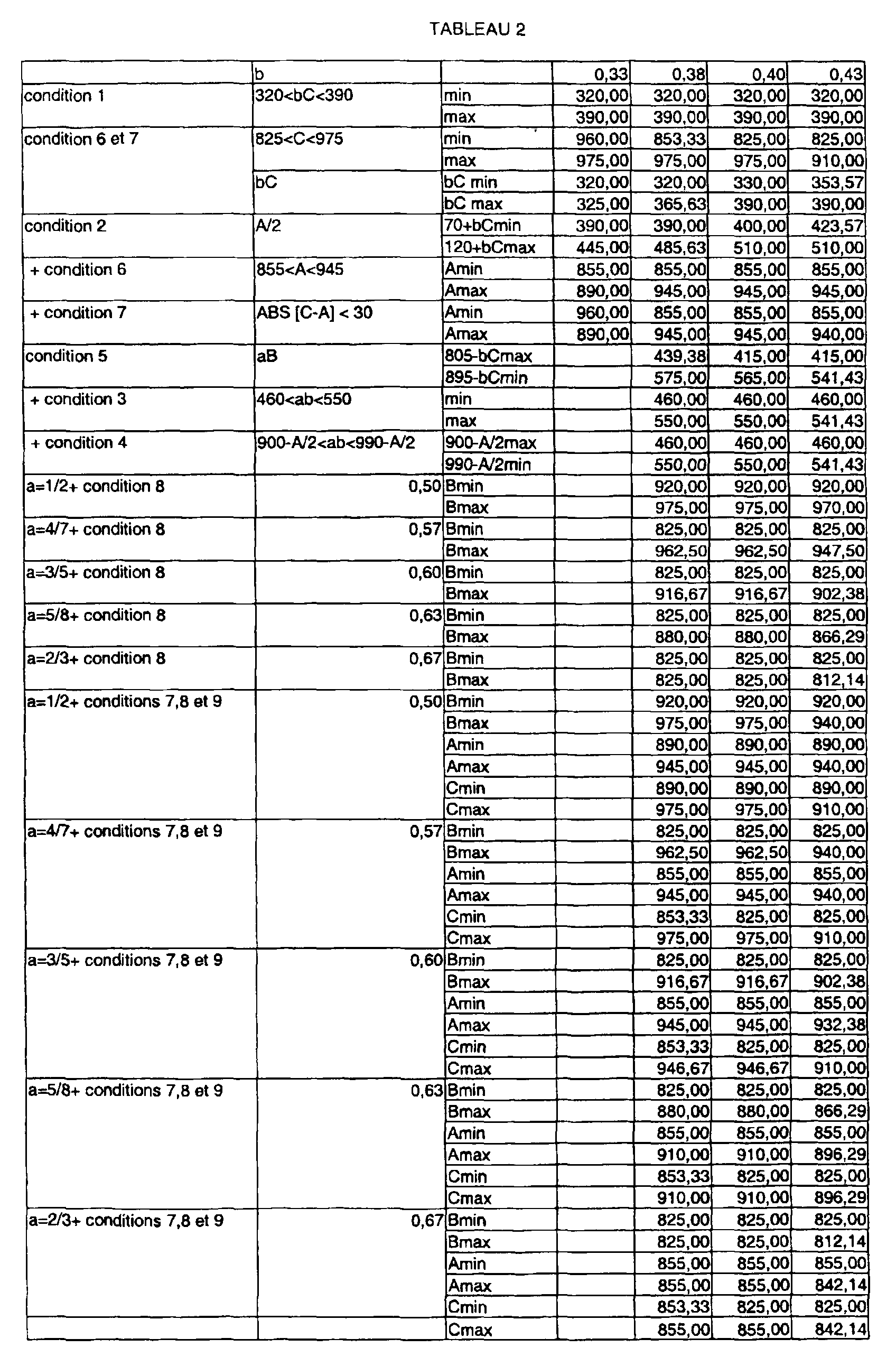
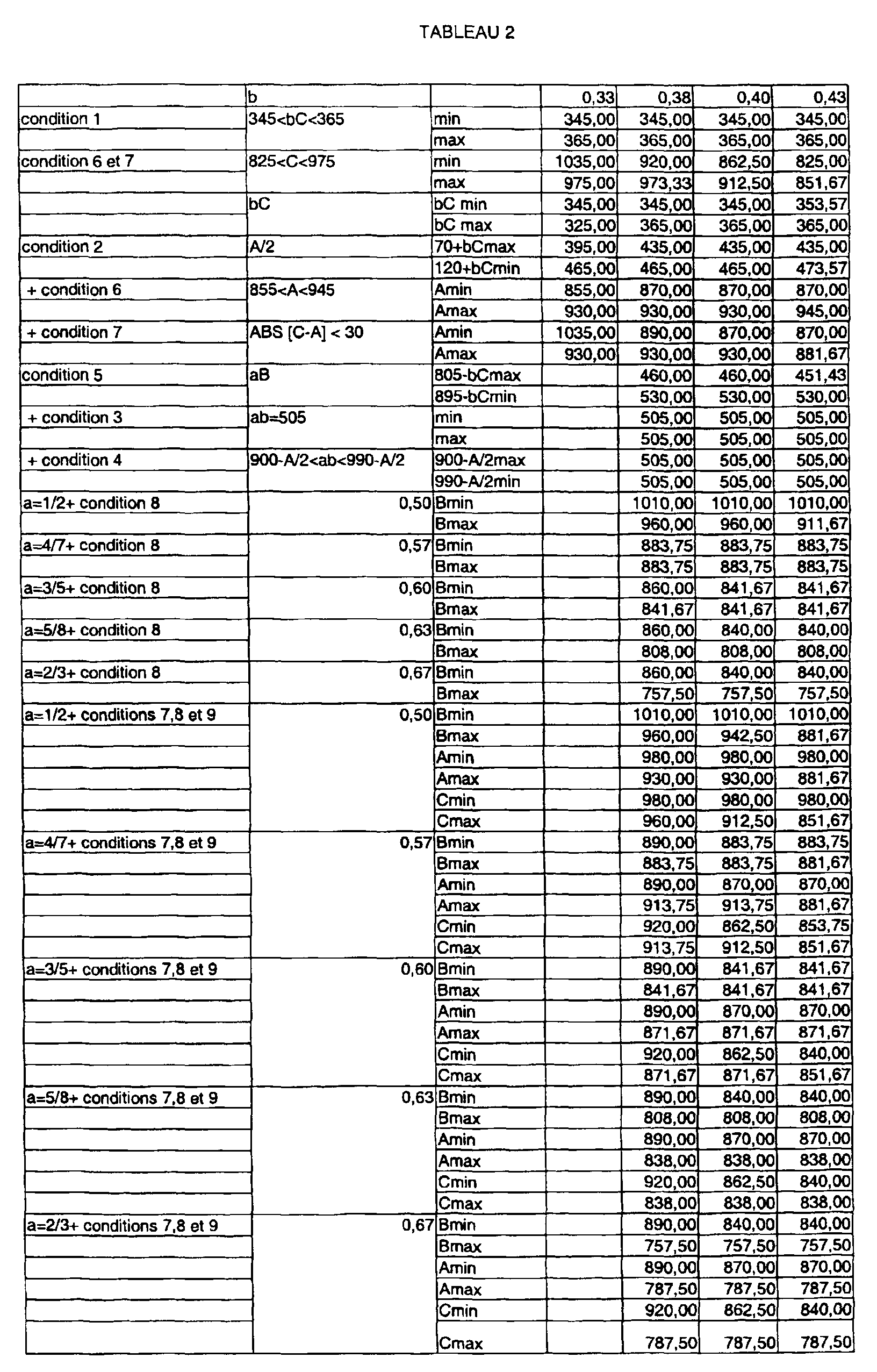
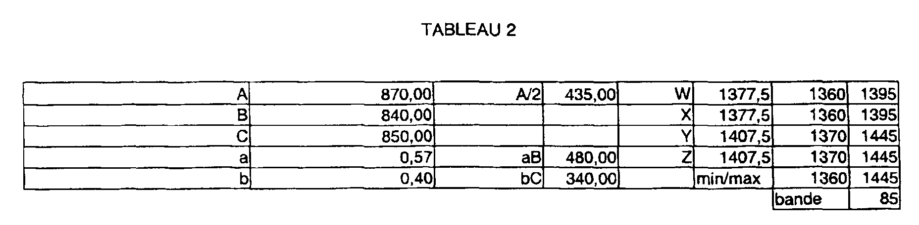
Claims (16)
caractérisé en ce qu'il comporte les étapes suivantes
characterized in that it comprises the following stages
Applications Claiming Priority (2)
| Application Number | Priority Date | Filing Date | Title |
|---|---|---|---|
| FR9814294 | 1998-11-13 | ||
| FR9814294A FR2786056B1 (en) | 1998-11-13 | 1998-11-13 | METHOD FOR SETTING A MULTIBAND TRANSMITTER FOR MOBILE TELEPHONY AND MOBILE TELEPHONE THUS OBTAINED |
Publications (1)
| Publication Number | Publication Date |
|---|---|
| EP1001548A1 true EP1001548A1 (en) | 2000-05-17 |
Family
ID=9532710
Family Applications (1)
| Application Number | Title | Priority Date | Filing Date |
|---|---|---|---|
| EP99402813A Withdrawn EP1001548A1 (en) | 1998-11-13 | 1999-11-12 | Method of adjusting a multiband mobile telephony transceiver and its corresponding mobile telephone |
Country Status (3)
| Country | Link |
|---|---|
| US (1) | US6434401B1 (en) |
| EP (1) | EP1001548A1 (en) |
| FR (1) | FR2786056B1 (en) |
Cited By (5)
| Publication number | Priority date | Publication date | Assignee | Title |
|---|---|---|---|---|
| EP1172940A2 (en) * | 2000-07-13 | 2002-01-16 | Sony Corporation | Multi-band transmission & reception-signal-generating apparatus |
| WO2002035723A1 (en) * | 2000-10-24 | 2002-05-02 | Siemens Aktiengesellschaft | Multiband terminal |
| WO2002075941A2 (en) * | 2001-03-15 | 2002-09-26 | Siemens Aktiengesellschaft | Method and device for producing mobile radio signals |
| EP1257065A1 (en) * | 2001-05-10 | 2002-11-13 | Sony International (Europe) GmbH | Frequency synthesiser for mobile terminals for wireless telecommunication systems |
| WO2010000336A1 (en) * | 2008-07-04 | 2010-01-07 | Siemens Aktiengesellschaft | Dual band radio communication using a common oscillator |
Families Citing this family (9)
| Publication number | Priority date | Publication date | Assignee | Title |
|---|---|---|---|---|
| FI112741B (en) | 1998-11-26 | 2003-12-31 | Nokia Corp | Method and arrangement for transmitting and receiving RF signals at various radio interfaces of communication systems |
| FR2822000B1 (en) * | 2001-03-08 | 2003-05-23 | Thomson Multimedia Sa | TRANSMISSION DEVICE LIMITING PARASITES OUTSIDE THE ALLOCATED FREQUENCY BAND |
| US20030096588A1 (en) * | 2001-11-20 | 2003-05-22 | Vanderhelm Ronald J. | Receiver intermod enhancer |
| US7366485B2 (en) * | 2004-03-04 | 2008-04-29 | Matsushita Electric Industrial Co., Ltd. | Multimode wireless transmitter and a portable wireless device using the same |
| JP4142058B2 (en) * | 2005-06-22 | 2008-08-27 | エプソンイメージングデバイス株式会社 | Electro-optical device and electronic apparatus |
| US20070281626A1 (en) * | 2006-06-05 | 2007-12-06 | Dobosz Paul J | Vehicle telematics satellite data transceiver utilizing fm radio circuitry |
| KR102268110B1 (en) * | 2014-08-05 | 2021-06-22 | 삼성전자주식회사 | Method and apparatus for modulating data and medium thereof |
| US20160380681A1 (en) * | 2015-06-25 | 2016-12-29 | Qualcomm Incorporated | Simplified multi-band/carrier carrier aggregation radio frequency front-end based on frequency-shifted antennas |
| CN110932743A (en) * | 2018-09-17 | 2020-03-27 | 天津大学青岛海洋技术研究院 | Vital sign Doppler radar circuit structure with double-frequency isolation effect |
Citations (6)
| Publication number | Priority date | Publication date | Assignee | Title |
|---|---|---|---|---|
| EP0581573A1 (en) * | 1992-07-28 | 1994-02-02 | Nokia Mobile Phones Ltd. | Universal radio telephone |
| EP0678974A2 (en) * | 1994-04-21 | 1995-10-25 | Nokia Mobile Phones Ltd. | A transmitter and/or receiver |
| US5649308A (en) * | 1993-04-12 | 1997-07-15 | Trw Inc. | Multiformat auto-handoff communications handset |
| GB2310342A (en) * | 1996-02-16 | 1997-08-20 | Northern Telecom Ltd | Dual mode radio transceiver front end |
| EP0800283A2 (en) * | 1996-04-01 | 1997-10-08 | Nokia Mobile Phones Ltd. | Transmitter/receiver for transmitting and receiving of an RF signal in two frequency bands |
| WO1998034341A1 (en) * | 1997-02-05 | 1998-08-06 | Ericsson Inc. | Transmit signal generation with the aid of a receiver |
Family Cites Families (2)
| Publication number | Priority date | Publication date | Assignee | Title |
|---|---|---|---|---|
| US5535432A (en) * | 1994-09-14 | 1996-07-09 | Ericsson Ge Mobile Communications Inc. | Dual-mode satellite/cellular phone with a frequency synthesizer |
| US6308048B1 (en) * | 1997-11-19 | 2001-10-23 | Ericsson Inc. | Simplified reference frequency distribution in a mobile phone |
-
1998
- 1998-11-13 FR FR9814294A patent/FR2786056B1/en not_active Expired - Fee Related
-
1999
- 1999-11-12 EP EP99402813A patent/EP1001548A1/en not_active Withdrawn
- 1999-11-12 US US09/432,583 patent/US6434401B1/en not_active Expired - Fee Related
Patent Citations (6)
| Publication number | Priority date | Publication date | Assignee | Title |
|---|---|---|---|---|
| EP0581573A1 (en) * | 1992-07-28 | 1994-02-02 | Nokia Mobile Phones Ltd. | Universal radio telephone |
| US5649308A (en) * | 1993-04-12 | 1997-07-15 | Trw Inc. | Multiformat auto-handoff communications handset |
| EP0678974A2 (en) * | 1994-04-21 | 1995-10-25 | Nokia Mobile Phones Ltd. | A transmitter and/or receiver |
| GB2310342A (en) * | 1996-02-16 | 1997-08-20 | Northern Telecom Ltd | Dual mode radio transceiver front end |
| EP0800283A2 (en) * | 1996-04-01 | 1997-10-08 | Nokia Mobile Phones Ltd. | Transmitter/receiver for transmitting and receiving of an RF signal in two frequency bands |
| WO1998034341A1 (en) * | 1997-02-05 | 1998-08-06 | Ericsson Inc. | Transmit signal generation with the aid of a receiver |
Cited By (8)
| Publication number | Priority date | Publication date | Assignee | Title |
|---|---|---|---|---|
| EP1172940A2 (en) * | 2000-07-13 | 2002-01-16 | Sony Corporation | Multi-band transmission & reception-signal-generating apparatus |
| EP1172940A3 (en) * | 2000-07-13 | 2003-12-17 | Sony Corporation | Multi-band transmission & reception-signal-generating apparatus |
| WO2002035723A1 (en) * | 2000-10-24 | 2002-05-02 | Siemens Aktiengesellschaft | Multiband terminal |
| WO2002075941A2 (en) * | 2001-03-15 | 2002-09-26 | Siemens Aktiengesellschaft | Method and device for producing mobile radio signals |
| WO2002075941A3 (en) * | 2001-03-15 | 2002-12-05 | Siemens Ag | Method and device for producing mobile radio signals |
| US7251465B2 (en) | 2001-03-15 | 2007-07-31 | Siemens Aktiengesellschaft | Method and apparatus for producing mobile radio signals |
| EP1257065A1 (en) * | 2001-05-10 | 2002-11-13 | Sony International (Europe) GmbH | Frequency synthesiser for mobile terminals for wireless telecommunication systems |
| WO2010000336A1 (en) * | 2008-07-04 | 2010-01-07 | Siemens Aktiengesellschaft | Dual band radio communication using a common oscillator |
Also Published As
| Publication number | Publication date |
|---|---|
| US6434401B1 (en) | 2002-08-13 |
| FR2786056A1 (en) | 2000-05-19 |
| FR2786056B1 (en) | 2000-12-22 |
Similar Documents
| Publication | Publication Date | Title |
|---|---|---|
| EP1001548A1 (en) | Method of adjusting a multiband mobile telephony transceiver and its corresponding mobile telephone | |
| FR2714242A1 (en) | Filtering device for use in a phase-locked loop controller. | |
| JP4236059B2 (en) | Frequency conversion circuit | |
| JP2002508132A (en) | Multi-mode direct demodulation receiver | |
| EP0631400A1 (en) | Portable transmitting and receiving device for two-mode digital signals | |
| EP1168634B1 (en) | Method for reducing the electricity consumption of a mobile cellular telephone | |
| EP1259077A1 (en) | Electronic component for decoding of a radio transmission channel carrying digitally coded information, especially for digital satellite broadcast | |
| FR2810173A1 (en) | RADIO FREQUENCY TRANSMISSION AND / OR RECEPTION DEVICE | |
| FR2787259A1 (en) | PHASE LOCKED LOOP FOR HIGH FREQUENCY SIGNALS | |
| FR2949631A1 (en) | BROADBAND RECEIVING TRANSMITTING DEVICE FOR TRANSMITTING AND RECEIVING SIGNALS FROM A SELECTED CHANNEL IN A DYNAMICALLY EXTENDED BANDWIDTH | |
| EP1152526B1 (en) | Zero-if tuner and corresponding control method | |
| EP1158679B1 (en) | Method and device for controlling the phase shift of four signals mutually in phase quadrature | |
| FR2759220A1 (en) | ANALOGUE SIGNAL PROCESSING CIRCUIT FOR SATELLITE POSITIONING RECEIVERS | |
| EP2412097A1 (en) | Frequency synthesizer | |
| EP1133060A1 (en) | Phase locked loop for generating a reference signal having a high spectral purity | |
| FR2943477A1 (en) | FREQUENCY DRIVING DEVICE FOR SATELLITE REMOTE TRANSMITTER / RECEIVER, RECEIVER TRANSMITTER THEREFOR | |
| EP1037479B1 (en) | Radiotelephone base station of local netwok connected to a cellular radio network | |
| FR2828624A1 (en) | TRANSMISSION / RECEPTION SYSTEM FOR MULTIBAND AND MULTIMODE MOBILE TELEPHONE | |
| EP1303061B1 (en) | Telecommunication system with low spurious electromagnetic radiations | |
| FR2853486A1 (en) | Signal decoding electronic component for digital television, has filtering stage in base bands arranged on two channels at output of transposition stage, and default error correction stage matching phase and amplitude of channels | |
| EP0531757B1 (en) | Method for controlling a frequency synthesizer provided with a modulation input | |
| FR2793619A1 (en) | DEVICE AND METHOD FOR PRODUCING A FILTER SIGNAL HAVING A GIVEN FREQUENCY AND A HERTZIAN TRANSMITTER TRANSMITTING AT A FREQUENCY ESTABLISHED BY A FREQUENCY ADJUSTABLE OSCILLATOR | |
| WO2006064012A1 (en) | Multiband microwave terminal | |
| WO2004036750A2 (en) | Radio-frequency device with null or quasi-null intermediate frequency minimizing interfering frequency modulation applied to an integrated local oscillator | |
| EP1071249B1 (en) | Modulation method and device in a transmitter |
Legal Events
| Date | Code | Title | Description |
|---|---|---|---|
| PUAI | Public reference made under article 153(3) epc to a published international application that has entered the european phase |
Free format text: ORIGINAL CODE: 0009012 |
|
| AK | Designated contracting states |
Kind code of ref document: A1 Designated state(s): DE ES FI GB IT SE |
|
| AX | Request for extension of the european patent |
Free format text: AL;LT;LV;MK;RO;SI |
|
| 17P | Request for examination filed |
Effective date: 20000823 |
|
| AKX | Designation fees paid |
Free format text: DE ES FI GB IT SE |
|
| RAP1 | Party data changed (applicant data changed or rights of an application transferred) |
Owner name: SAGEM S.A. |
|
| GRAP | Despatch of communication of intention to grant a patent |
Free format text: ORIGINAL CODE: EPIDOSNIGR1 |
|
| GRAS | Grant fee paid |
Free format text: ORIGINAL CODE: EPIDOSNIGR3 |
|
| STAA | Information on the status of an ep patent application or granted ep patent |
Free format text: STATUS: THE APPLICATION IS DEEMED TO BE WITHDRAWN |
|
| 18D | Application deemed to be withdrawn |
Effective date: 20060601 |