EP1003095A2 - A computer system for executing branch instructions - Google Patents
A computer system for executing branch instructions Download PDFInfo
- Publication number
- EP1003095A2 EP1003095A2 EP00102080A EP00102080A EP1003095A2 EP 1003095 A2 EP1003095 A2 EP 1003095A2 EP 00102080 A EP00102080 A EP 00102080A EP 00102080 A EP00102080 A EP 00102080A EP 1003095 A2 EP1003095 A2 EP 1003095A2
- Authority
- EP
- European Patent Office
- Prior art keywords
- instruction
- instructions
- branch
- fetcher
- address
- Prior art date
- Legal status (The legal status is an assumption and is not a legal conclusion. Google has not performed a legal analysis and makes no representation as to the accuracy of the status listed.)
- Granted
Links
- 230000000694 effects Effects 0.000 claims abstract description 58
- 238000000034 method Methods 0.000 claims abstract description 49
- 239000000872 buffer Substances 0.000 claims description 42
- 238000010586 diagram Methods 0.000 description 12
- 230000008859 change Effects 0.000 description 7
- 230000008901 benefit Effects 0.000 description 3
- 230000006870 function Effects 0.000 description 3
- 230000007246 mechanism Effects 0.000 description 3
- 238000000926 separation method Methods 0.000 description 2
- 230000009471 action Effects 0.000 description 1
- 230000006399 behavior Effects 0.000 description 1
- 230000001934 delay Effects 0.000 description 1
- 230000003111 delayed effect Effects 0.000 description 1
- 238000001514 detection method Methods 0.000 description 1
- 230000006872 improvement Effects 0.000 description 1
- 230000008520 organization Effects 0.000 description 1
- 230000004044 response Effects 0.000 description 1
- 239000002699 waste material Substances 0.000 description 1
Images


Classifications
-
- G—PHYSICS
- G06—COMPUTING; CALCULATING OR COUNTING
- G06F—ELECTRIC DIGITAL DATA PROCESSING
- G06F9/00—Arrangements for program control, e.g. control units
- G06F9/06—Arrangements for program control, e.g. control units using stored programs, i.e. using an internal store of processing equipment to receive or retain programs
- G06F9/30—Arrangements for executing machine instructions, e.g. instruction decode
- G06F9/38—Concurrent instruction execution, e.g. pipeline, look ahead
- G06F9/3802—Instruction prefetching
- G06F9/3804—Instruction prefetching for branches, e.g. hedging, branch folding
-
- G—PHYSICS
- G06—COMPUTING; CALCULATING OR COUNTING
- G06F—ELECTRIC DIGITAL DATA PROCESSING
- G06F9/00—Arrangements for program control, e.g. control units
- G06F9/06—Arrangements for program control, e.g. control units using stored programs, i.e. using an internal store of processing equipment to receive or retain programs
- G06F9/30—Arrangements for executing machine instructions, e.g. instruction decode
- G06F9/38—Concurrent instruction execution, e.g. pipeline, look ahead
- G06F9/3836—Instruction issuing, e.g. dynamic instruction scheduling or out of order instruction execution
- G06F9/3842—Speculative instruction execution
Definitions
- This invention relates to a computer system for executing branch instructions and to a method for operating such a computer system.
- Programs consist of blocks or strings of sequential instructions, which have a single entry point (the first instruction) and a single exit point (the last instruction). There are one or two choices of instruction blocks to be executed after any particular block. When there are two possible blocks, a condition must be used to determine which block to choose. The pattern of links between blocks is called the program's control or flow graph.
- Block B When there is no choice of subsequent block (block B), it can normally be placed immediately after the first block (block A). This means that there need not be any explicit change in control to get from block A to block B. Sometimes this is not possible, for instance, if more than one block has block B as a successor. All but one of these predecessors must indicate that the subsequent block will not be the next sequential block, but block B. These are unconditional branches. Some blocks have a choice of successor blocks. Clearly only one of the successors, for example block B, can be placed sequentially afterwards. The other block, block C, is indicated explicitly within block A. A conditional mechanism is used to determine which block is to be chosen. If the condition is met, then the chosen successor block is block C. If the condition is not met, then the chosen successor is block B. These are conditional branches.
- Branch instructions are used to change this behaviour. These branch instructions specify an alternative address (the target location) for the next executable instruction.
- Conditional branch instructions also specify a condition which must be met for the alternative address to be used - otherwise the instruction pointer will be incremented as usual.
- the computer fetches, decodes and executes to completion one instruction, before moving on to the next instruction.
- fetch, decode and execution stages can all operate simultaneously on a stream of instructions.
- fetch instructions which are not required. For instance, consider a system with a four stage instruction pipeline with fetch, decode, execute and write stages. The earliest that a branch instruction can be detected is in the decode stage, by which time the next sequential instruction in memory will have already been fetched. For an unconditional branch this must be thrown away, and new instructions fetched from the target location. For conditional branches it is more complicated. The condition must be evaluated to determine whether or not to change to the target location.
- FIG. 1 illustrates schematically this operation.
- the branch instruction is detected in the decode stage.
- the branch delay slot is Inst 1, which is always executed.
- Inst D0 being the first instruction of a different block
- Inst 2 which is the first instruction of the next sequential block.
- Inst 1 must be an instruction which can always be executed, regardless of the outcome of the (conditional) branch, and it must not be an instruction which determines whether the conditional branch is to be taken. If no instruction can be found within the program which satisfies these conditions, then an instruction which has no effect (NO OP) must be inserted instead.
- Pipelines can be designed where the optimum number of delay slots is more than one. The more deeply pipelined a computer is, the more delay slots are generally required. Unfortunately, it gets harder and harder to find useful instructions to put in each additional slot, so many of them are filled with instructions which do nothing. This places large bubbles of NO OP instructions in the execution pipeline, thus reducing the speed advantage obtained by making a deep pipeline.
- one known system uses two instruction fetchers at the fetch stage of a pipeline, each instruction fetcher being capable of fetching and holding a sequence of instructions.
- One instruction fetcher has associated with it local decode circuitry which is arranged to detect branch instructions. It will be appreciated that this local decode circuitry is in addition to the normal decode stage of the pipeline.
- branch instruction When a branch instruction is detected by the active fetcher it initialises the other instruction fetcher to start fetching instructions from the new block while the instructions up to the branch instruction of the first block continue to be passed into the pipeline for decoding and execution.
- this system require extra local decode circuitry to detect branch instructions prior to the normal decode stage of the pipeline, but it also involves speculative fetching of instructions from the memory, many of which may not be required.
- EP-A-355069 (Evans & Sutherland Computer Corporation) defines a system in which there is separation of the instruction to effect a branch into two different parts.
- the set branch instruction indicates the target location for the branch and can be placed as near the beginning of the string of instructions as possible.
- the provision of the target location for the branch with the set branch instruction provides an early indication of the fact that a memory access is going to be made (or is likely to be made) and provides the memory address (the target location) for that access.
- the split bit causes the branch to be taken, and the time comes therefore to access that memory address, the system has had a chance to set up for the access, for example by bringing the necessary data into a local cache.
- One problem associated with the system of EP-A-355069 is that the target location from which new instructions are fetched is reset after a split bit signal has been executed. This means that there cannot be multiple branches using the target location set up by a single set branch instruction. It is advantageous to allow for this situation and it is one object of the present invention to provide an improved system for implementing branches allowing for this.
- a computer system for fetching, decoding and executing instructions comprising:
- the invention also provides a method of operating a computer to fetch decode and execute instructions which computer has storage circuitry holding a plurality of instructions at respective storage locations, said plurality of instructions being arranged in instruction strings, each string comprising a first instruction and a set of subsequent instructions the method comprising:
- said instruction fetch circuitry comprises two instruction buffers, a first buffer for holding subsequent instructions connected to said execution circuitry, and a second buffer for holding new instructions wherein the contents of said second buffer are copied into said first buffer responsive to generation of said effect branch (DO) signal.
- DO effect branch
- said instruction fetch circuitry includes two instruction fetchers for fetching respectively said subsequent instructions and said new instructions and wherein said select circuitry is operable to connect a selected one of said instruction fetchers to said execution circuitry.
- the target store can hold the memory address of the target location.
- the set branch instruction can identify the target location using an implicit value which addresses a special register holding the memory address of the new instructions.
- the target store can hold a pointer to a memory location which contains the memory address of the target location.
- the effect branch signal is generated when the branch point, at which the branch is to be taken, is identified.
- a further instruction can be located in the string of instructions being executed prior to the branch point in which case said further instruction will identify the branch point which will be held in a branch point register.
- the contents of the branch point register can then be compared with an instruction pointer register holding an indication of the address from which a next instruction would normally be fetched and when the two are equal the effect branch signal is generated.
- Alternative methods for identifying the branch point are also discussed herein.
- the set branch instruction itself can identify the branch point which is stored in the branch point register, thereby obviating the need for a further instruction.
- the branch point is identified by a further, dedicated instruction, different to the set branch instruction, which is located at the branch point in the string of instructions being executed.
- this effect branch instruction can itself define the condition to be satisfied so that a branch is only taken if the condition is satisfied and is not taken if the condition not satisfied.
- the set branch instruction itself must indicate whether or not the branch is conditional or not and cause various different condition detectors to be in a ready state, ready to sense a condition.
- the condition itself is defined in an instruction different to the set branch instruction and to the split bit instruction.
- the present invention provides in another aspect a computer system for fetching, decoding and executing instructions comprising:
- the invention also provides in a further aspect a method of operating a computer to fetch decode and execute instructions which computer has storage circuitry holding a plurality of instructions at respective storage locations, said plurality of instructions being arranged in instruction strings, each string comprising a first instruction and a set of subsequent instructions the method comprising:
- the computer system can include circuitry for holding a state indicator in one of a confirmed state and a rejected state.
- the confirmed state is one in which further instructions to be executed are new instructions commencing from the target location.
- the rejected state is one in which further instructions to be executed are subsequent instructions in memory and not new instructions.
- One of the states can be set responsive to execution of the set branch instruction and the other of the states can be selectively set responsive to execution of a second instruction different from the set branch instruction and subject to a condition.
- the second instruction can be a confirm instruction which sets the confirmed state if the confirm condition is satisfied.
- the second instruction could be a reject instruction which sets the rejected state if the reject condition is satisfied.
- reject or confirm instructions allows a further improvement to be made in that the set branch instruction is the first instruction of the string and there is a plurality of contiguous instruction strings, with the set branch instruction acting as a further instruction to generate the effect branch signal if the state indicator is in the confirmed state. It will be appreciated that the set branch instruction acting as the further instruction will also change the state of the state indicator back to its original state.
- the confirm/reject instruction can be placed as early as possible within the string (after the condition has been generated) so that the execution circuitry can be given an early indication of which way the branch will go.
- Figure 2 illustrates three blocks of instructions in memory, Block A, Block B and Block C.
- Each block comprises a first instruction which in each case is a set branch instruction Set B, Set C, Set D, respectively, a sequence of subsequent instructions for example Inst A1, Inst A2 ... Inst Ai-1 in Block A and a last instruction which in each case is an effect branch instruction referred to herein as D0.
- D0 effect branch instruction
- a target location for a branch is stored, in this case identifying the memory address of the first instruction Set C of Block B.
- no action is taken at this stage other than to store the target location and possibly to set up the memory containing Block B for an access, for example by moving the relevant memory addresses to a local cache.
- the instructions in Block A continue to be fetched, decoded and executed until the last instruction, D0, is being executed. Execution of this instruction causes an effect branch signal to be generated which causes the execution unit to address as its next instruction the target location set up by the set instruction Set B.
- the next instruction to be fetched from memory is the first instruction Set C of Block B. This is indicated by the dotted arrow in Figure 2.
- Figure 2 illustrates the case for unconditional branches, that is branches that will inevitably be taken.
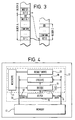
- Figure 3 illustrates the position for conditional branches, that is branches that may or may not be taken depending on whether or not a condition which has been evaluated is satisfied.
- Figure 3 illustrates the case where a third instruction is used in addition to the set branch instruction and effect branch instruction described above with reference to Figure 2. In Figure 3 this third instruction is referred to as CONFIRM, although it will become clearer in the following that it is possible to implement conditional branches using a reject instruction with the opposite semantics.
- conditional branches using a conditional DO instruction.
- FIG. 3 illustrates three sequences of instructions held in memory as Block A, Block B and Block C.
- Block B is shown contiguous to Block A and is arranged in memory such that if instructions are fetched from memory using sequential memory addresses then instructions will be normally fetched in the sequence of Block A followed by Block B.
- Block C is shown located elsewhere in memory.
- each block comprises a first instruction which is a set branch instruction (Set C in Block A, Set D in Block B and Set E in Block C).
- Block A then additionally comprises a sequence of instructions to be executed including a confirm instruction and the last instruction which is the effect branch instruction.
- instructions are fetched, decoded and executed.
- the first instruction of Block A When the first instruction of Block A is executed it is identifed as a set branch instruction with a target location identifying the memory address of the first instruction Set E in Block C. Instructions in Block A continue to be fetched, decoded and executed until the confirm instruction is reached which has a condition associated with it. If the condition is satisfied, the branch is confirmed and execution of the effect branch instruction D0 at the end of Block A will cause the branch identified by the target location to be taken as indicated by the dotted line in Figure 3. Thus, the next instruction to be fetched, decoded and executed will be the first instruction Set E of Block C.
- the branch will not be taken when the effect branch instruction is executed but instead the next instruction to be fetched, decoded and executed will be the first instruction Set D of Block B which sequentially follows Block A in memory. It will readily be appreciated that once confirm instructions has been introduced, it will be necessary even to confirm unconditional branches such as that which is illustrated by way of example in Block C, where the branch is always confirmed and is not subject to a condition.
- any useful computer system must be capable of implementing conditional branches in addition to unconditional branches. It will be appreciated that in order to implement branches as described above with reference to Figures 2 and 3, a target register must be provided for storing the target location indicated by the set branch instruction. Moreover, for conditional branches a state indicator must be provided to indicate whether the branch is in a confirmed state or not. A detailed explanation of circuitry capable of implementing the present invention is given later. Firstly, there follows an explanation of the various different ways in which branch instructions in accordance with the present invention may be implemented.
- This mechanism is similar to Method A, except that the branch has to be rejected, rather than confirmed.
- the set instruction initializes the branch target register, and sets the state to branch.
- the reject instruction conditionally sets the state to not branch.
- the do instruction executes the initialized branch, if the state is still at branch. With these semantics, the reject instruction is optional, unconditional branches would not need one. There can be more than one reject instruction, if any nullify the branch, then the branch will not be taken.
- This method combines the confirm and do instructions, so that do becomes a conditional do. There is no requirement for a state machine to hold whether the branch is to be taken or not.
- This scheme delays the effect of the do instruction by a variable amount ( ⁇ offset ⁇ ). This permits unnecessary instruction fetching to be stopped at the end of the block of instructions.
- branch point The end of the block (branch point) is indicated in the do instruction, either as an offset to the last instruction in the block, the first instruction in the subsequent block or as an instruction count to the end of the block.
- Two registers are required, one bit of state to record whether the branch has been confirmed or not, and a branch point register to hold the block termination address or count, as an indication of the branch point.
- This scheme is similar to Method D, except that the branch is conditionally rejected, rather than confirmed.
- the reject instruction is optional.
- This scheme is similar to Method D, except that the branch point is specified with the set instruction, thus removing the requirement for a do instruction. The branch still needs to be confirmed, otherwise it will be ignored. Two additional registers are required, one bit of state to record whether the branch has been confirmed or not, and a branch point register to hold the block termination offset or count as an indication of the branch point.
- This method is a combination of Method C and Method D.
- the set instruction specifies the branch target location, whilst the do instruction specifies both a branch point and the condition on whether the branch is to be executed. Two pieces of state are required to support this, a branch point register to hold the branch point and one to hold whether the branch is to be executed or not. Both of these are set by the do instruction. If the condition is false, the processor stays in the unbranching state. Unconditional branches could either specify a true condition, or use a special unconditional do instruction.
- the set instruction is executed only once. The same branch target is required for each iteration of the loop.
- the subsequent set instruction at the beginning of the next block is executed as though it were a do instruction to effect the branch. If the system is not in a branch state when the set instruction at the beginning of the next block is executed, the branch will not be taken and the set instruction will be executed in the normal manner to set up a branch with a target location.
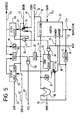
- FIG. 4 is a simplified block diagram of a pipelined computer system.
- a memory 41 which in this example comprises a conventional RAM.
- the computer system includes an address bus 39 and a data bus 43 coupled to the memory 41. It will be appreciated that read and write control signals for the memory are required but they are not illustrated in Figure 4.
- the memory 41 holds program comprising sequences of instructions at different addressable locations, as already described above with reference to Figures 2 and 3.
- the memory 41 may also hold data.
- the data bus 43 carries data values to and from the memory 41.
- the address bus 39 carries memory address values for read or write operations.
- the computer system comprises an instruction fetch circuit 10 which is arranged to supply addresses to memory along address line 12 and to receive instructions from memory along data line 14.
- a decode circuit 16 is connected to receive instructions fetched by the fetch circuit and supplied on instruction line 22 and decodes them.
- the decode circuit 16 supplies instructions to an execution circuit 18 which executes instructions and controls a result write circuit 20 to write results of the execution into temporary registers 11.
- the decode circuit 16, execution circuit 18, result write circuit 20 and registers 11 are conventional and are not described further herein. They are referred to together in the following as the processor 17.
- the fetch circuit 10 is arranged to fetch four bytes at a time from the memory 41 and to provide instructions along instruction line 22 to the decode circuit 16. Where the instructions are of variable length, it will be appreciated that an alignment mechanism is required within the instruction fetch circuit to deal with instructions which are not exactly four bytes long and to correctly align these instructions. Circuitry to accomplish this is described in our copending EP Application No. 95303608.4 (Compressed Instruction Set). The present invention can be implemented with same length or variable length instruction sets.
- the fetch circuit 10 comprises two instruction fetchers, one of which will now be described with reference to Figure 5.
- the data line 14a and address line 12a are connected to the corresponding lines 14 and 12 illustrated in Figure 4.
- the fetcher includes a fetch pointer 65 which comprises a 32 bit latch containing the next address in memory from which a 32 bit word is to be read. Whenever a value is read from memory, the fetch pointer 65 is normally increased by four bytes to a new pointer address via an increment unit 38.
- the fetcher is arranged to read instructions from memory on data line 14 into an instruction buffer 66 from which they are output along instruction line 22 to the processor 17.
- a length indicator 74 is provided which receives on line 70 an indication from the instruction buffer 66 of the length of the instruction which has been output.
- the length indicator 74 generates an amount signal 86 which indicates the number of bytes used by the instruction being output.
- a byte counter 75 holds a count of the number of bytes in the instruction buffer 66 at any one time and generates a select signal 24 which determines where in the instruction buffer 66 bytes fetched from the memory 41 are to be inserted.
- the instruction buffer 66 also receives a remove signal 26 which causes an instruction to be removed from the buffer. Unremoved instructions are shifted along, thereby creating space at the end of the buffer for more bytes from the memory 41.
- the instruction buffer 56 is also responsive to a store signal 28 which causes bytes from the memory to be stored in the buffer at the location indicated by the select signal 24.
- the store signal 28 is derived from a latch signal 30 which is used to indicate that data can be stored from the memory.
- the fetch pointer 65 is supplied with an address on line 32 from a fetch multiplexor 34 which has one input connected to receive a next address on line 36 from the increment unit 38.
- the increment unit 38 updates the fetch address in the usual manner, in this example by four bytes each time.
- the other input of the fetch multiplexor 34 is connected to a start line 40 on which is supplied a new address from which fetching is to be commenced. It will readily be appreciated that for the purposes of branching the new address is derived from the target location identified in the set branch instruction.
- a begin signal 42 controls the fetch multiplexor 34 to start fetching from a new address on the start line 40.
- the fetch pointer 65 has its latch input connected to an OR gate 44 which receives the begin signal 42 and the latch signal 30 to control latching of subsequent addresses into the fetch pointer 65.
- the latch signal 30 is also supplied to a gate 46 which is connected to the latch input of the byte counter 75 and which receives as its other input a next signal 48 which is used to indicate that an instruction has been read from the instruction buffer 66 and which thus latches the appropriate byte count.
- the begin signal 42 is also fed to the clear input of the byte counter 75 and to the clear input of a stop latch 50.
- the stop latch 50 receives on the Stop At line 52 the address after which no further instructions are to be fetched. This address is stored in the stop latch 50 under the control of a stop signal 54.
- the output of the stop latch 50 is fed to a comparator 56 which also receives the memory address on line 12.
- the comparator 56 determines whether or not the memory address on line 12 has reached the address stored at the stop latch 50.
- the output of the comparator 56 is supplied to a gate 58 which also receives the output from a check full unit 80.
- the check full unit 80 receives the output from the byte counter 75 and asserts its output whenever the buffer 66 is full.
- the output of the gate 58 provides a full signal on line 82 which indicates either that the instruction buffer 66 is full or that the stop address has been reached. No further memory requests will be performed when the full signal 82 is asserted.
- the output of the byte counter 75 is also fed to a second increment unit 84 the output of which is fed to one input of a count multiplexor 85.
- the other input of the count multiplexor 85 is supplied from a subtract unit 90 which receives the output from the byte counter 75 and the output from the length indicator 74.
- the subtract unit 90 asserts a more signal 92 whenever the instruction buffer does not contain at least one instruction.
- a start address which is the memory address identifying the first four bytes at the beginning of a block of instructions is supplied on line 40 to the fetch multiplexor 34.
- the begin signal 42 is asserted to clear the stop latch 50 and to latch the start address into the fetch pointer 65.
- a memory access is made at that address and the first four bytes are supplied along data line 14 to the instruction buffer 66.
- the latch signal 30 causes these four bytes to be stored in the buffer and latches a next address into the fetch pointer 65. This next address will now be the start address incremented by four bytes by the increment unit 38, unless a branch is being taken as described more fully later.
- the instruction buffer 66 supplies an instruction along line 22 and indicates the length of the instruction on line 70 to the length indicator 74.
- the output of the length indicator 74 supplies the amount signal 86 to indicate the size of the instruction which has been removed and also supplies an input to the subtract unit 90 which provides a count to the byte counter 75 to enable it to assert the select signal 24 to determine where in the buffer the next four bytes fetched from memory should be stored.
- the stop latch 50 is used to store an address which the fetcher should not advance past. On commencement of fetching at the start address the stop latch 50 is cleared to an invalid address by the begin signal 42. Storing a special address in the stop latch 50 will stop fetching. The use of the stop latch 50 will become clearer in the following description of the application of the fetcher unit.
- the target location identified by the branch instruction is used to provide the start address on line 40 for the instruction fetcher when the effect branch signal has been supplied to cause a branch to be taken.
- the fetcher thus commences fetching of instructions from the new target location.
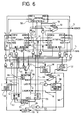
- the fetch circuit 10 of Figure 4 includes two instruction fetchers of the type described above with reference to Figure 5. Reference will now be made to Figure 6 to describe in more detail how branch instructions control the activity of the instruction fetchers.
- the fetchers are illustrated as Fetcher A and Fetcher B.
- the system includes an arbitrator unit 100 which arbitrates between Fetcher A and Fetcher B for access to the memory using the full and more signals from each fetcher to determine which requires data.
- the full and more signals for Fetcher A are referred to at the arbitrator as more A and full A and the full and more signals for Fetcher B are referred to at the arbitrator as more B and full B.
- Reference numerals relating to Fetcher A correspond to those for the instruction fetcher shown in Figure 5.
- the address outputs 12a of the Fetchers A and B are supplied through an address multiplexor 102 to the address line 12.
- the multiplexor is controlled by a Sel A signal on line 104 from the arbitrator 100 which gives priority to the fetcher which is currently fetching instructions for execution. It will be appreciated that one of the fetchers is used to fetch instructions in the current block (and potentially the next sequential block) and the other fetcher is used to fetch instructions commencing from the target location. Both fetchers receive instructions along data line 14 and supply their instructions on line 22a to a select multiplexor 104.
- the output 22 of the multiplexor 104 is connected to the processor 17 which decodes and executes instructions and writes the results to temporary registers 11.
- the processor 17 supplies the next signal which is fed to the instruction fetchers on line 48.
- the processor 17 receives a wait signal on line 106 which is derived from the more signals 92 of the fetchers.
- As the processor 17 executes instructions it updates an instruction pointer register 108 to point to the next instruction to be executed by supplying an output on the new IP line 110 via a pointer multiplexor 112.
- a latch IP signal on line 114 indicates when the instruction pointer register 108 is to be updated.
- the output of the instruction pointer register 108 provides the current value of the instruction pointer on a current IP line 116.
- the computer system of Figure 6 also includes a target pointer register 118 for holding a target location identified by a set branch instruction and a branch pointer register 120 for holding a value identifying the point at which the branch is to be taken.
- the computer system also includes an active fetcher switch 122 which controls which of the fetchers A and B is supplying instructions to the processor 17.
- a check output from the processor 17 on line 126 is fed via a gate 128 to control the pointer multiplexor 112 and the active fetcher switch 122.
- the gate 128 also has an input on line 130 from the compare unit 124.
- the execution circuit of the processor 17 includes a set branch instruction execution unit 136 and a do instruction execution unit 142.
- the computer system also includes a state indicator 132 for holding an indication of the state of the system, that is whether it is in a branch state or not.
- the processor 17 is to execute block A of Figure 3.
- the start address identifying the beginning of the first instruction of block A is supplied to fetcher A.
- the first instruction is supplied on line 22a to the multiplexor 104 which is controlled by a signal on line 134 from the active fetcher switch 122 so that instructions from fetcher A are supplied to processor 17.
- the first instruction is a set branch instruction Set C which is identified by the set branch execution unit 136 forming part of the processor 17.
- the set branch execution unit 136 generates the appropriate target location on target line 138 and a set signal on line 140.
- the set signal is used to activate the begin signal 42 for fetcher B so that that fetcher is initialised to commence starting to fetch instructions from the target location.
- the target location is also stored in the target pointer register 118. Instructions in block A continue to be supplied by fetcher A from memory to the processor 17 and executed. On execution of the confirm instruction, the condition for the confirm instruction is evaluated and the state indicator 132 is appropriately set. The condition line 145 indicates the state of the system which is selectively supplied to the stop lines 54 and the fetchers as described later. The following description assumes that the condition for the confirm state has been positive so that the system is in a branch state. After fetching decoding and execution of further instructions up to and including Inst A-1 in block A, the next instruction is an effect branch instruction. This is executed by the do instruction execution unit 142 which forms part of the processor 17.
- the branch point On execution of the effect branch instruction by this unit 142, the branch point is calculated (the first address of the first instruction at the beginning of the next sequential block) and is supplied to the branch pointer register 120 along line 144.
- the branch point is also supplied to the stop latches 50 of the fetchers.
- the stop signal 54 is asserted for Fetcher A via the condition line 145 and not for Fetcher B. Therefore Fetcher A latches the stop address so that it will stop fetching when that address is reached.
- the output of the compare unit 124 causes an effect branch signal to be asserted on line 146.
- the desription given above relating to the computer system of Figure 6 is for a system including a branch point register and a state indicator for holding the state of the system. As mentioned earlier, these may be omitted if a method such as method C is utilised in which the effect branch signal is a conditional signal located at the branch point.
- the set branch instruction sets the target location into the target pointer register 118 as described above.
- the effect branch instruction is executed, the condition defined in the instruction is evaluated. If that condition is true, the effect branch signal 146 is supplied to cause fetcher B to become the active fetcher commencing fetching from the target location so that the branch is taken.
- the target location remains valid in the target pointer register 118 and, instead of fetcher A being controlled to stop fetching as described above, it is caused to commence fetching new instructions from the target location. This has the advantage that if a further branch should be required having a target location defined by the set instruction, the new instructions have already been fetched.
- fetcher A and fetcher B swop over their roles.
- the target location remains valid and stored in the target pointer register 118 until execution of the next set instruction, which resets a new target location in the target pointer register 118.
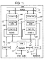
- FIG 11 is a block diagram illustrating this principal.
- reference numerals 39 and 43 denote the address bus and data bus as in preceding figures.
- the fetch circuitry 10 in Figure 4 is implemented by an execute instruction fetcher 402 and a target instruction fetcher 404. These are denoted fetcher E and fetcher T respectively. Like elements in each fetcher have the same reference numeral, suffixed E or T appropriately.
- Each fetcher comprises a fetch pointer 406 for holding an indication of the next address from which instructions are to be fetched and a start pointer 408 for holding the target location representing the first instruction in a new string of instructions.
- Each fetcher also has a buffer 410 for holding a queue of instructions.
- Reference numeral 118 denotes as before the target pointer register which holds an indication of the target location responsive to execution of the set branch instruction.
- Reference numeral 412 denotes a select circuit for selecting the one of the fetchers acting as the execute Fetcher E to supply its instructions to the decode circuit 16 of Figure 4.
- a sequencer 414 receives the effect branch signal 146 and has state which changes on receipt of that signal to cause the role of the fetchers to alter as described above, by controlling the select circuit 412 along line 411.
- the sequence 414 can also provide signals to the fetchers 408E,T along lines 418E,418T respectively.
- the sequencer supplies a signal on line 418E to cause Fetcher E to commence obtaining instructions from the target location.
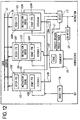
- Figure 12 is a block diagram illustrating a system for implementing such an arrangement.
- like numerals denote like parts as in Figure 11 for the execute instruction fetcher and the target instruction fetcher and the other features common between Figures 11 and 12.
- the system of Figure 12 additionally includes a mispredict fetcher 403, fetcher M.
- This likewise has a fetch pointer register 406M for holding the address from which next instructions are to be fetched, a buffer 410M for holding a queue of instructions and a start pointer register 408M for holding the start address from which instructions are to be fetched.
- the select circuit 412 is arranged to select the one of the three fetchers acting as the execute fetcher E to supply instructions to the decode circuitry 16.
- the execute fetcher 402 fetches the normal sequence of instructions for supply to the execution unit.
- the target fetcher 404 fetches instructions beginning from the target location, and thus holds the next branch target instruction.
- the mispredict fetcher 403 fetches instructions which are located at a branch resulting from a conditional instruction which probably will not be satisfied. This is referred to as a predicted to be not used arm of a branch. If it is subsequently determined that a conditional branch was predicted the wrong way, the correct sequence of instructions is held in this fetcher.
- an indication of the target location is loaded into the target pointer register 118 as before.
- the target fetcher 404 is cleared and starts fetching instructions from the target location.
- Detection of despatch of these conditional DO instruction to the execution unit is undertaken by a detect unit 413. This supplies Predict Taken and Predict Untaken signals to the sequencer 414.
- This arrangement can be implemented in a variety of different ways without affecting the concept. For example, when the fetchers are renamed the contents of the outgoing target fetcher could be copied to the incoming target fetcher. This means that the new target fetcher does not waste time refetching these instructions. It would continue the fetching from where the outgoing target fetcher left off, provided it is not full. Alternatively, the fetchers need not be renamed dynamically, but their contents transferred as appropriate. This would remove any requirement for state in the sequencer 414.
- kernel branches Many processors have two modes of operation, one for normal programs and one for special programs. These are referred to as user and kernel modes. Kernal mode has more instructions available to it which are used to manipulate the operation of the computer. This separation is required to prevent an erroneous or malicious user mode program from causing damage to other user mode programs. Kernel mode programs can be assumed to be correct. There is therefore a need for a method to change a programs mode from user to kernel. This is done by branching to a special target location, called the kernel entry point. With the present invention this is implemented using a special set branch instruction, which does not specify the branch target location explicitly but uses an implicit value. Some state must be used to specify that when the branch occurs, the processor must change to kernel mode.
- branch instruction is a so-called descriptor branch, which is a call via a pointer.
- This branch instruction specifies an address in memory, but it is not the address representing the target location of the branch. Instead, it is a memory location containing the target location for the branch.
- Figure 7 illustrates an instruction fetcher which can be used to implement kernel and descriptor branches. Like numerals in Figure 7 denote like parts in Figure 5.
- the fetcher of Figure 7 has the following additional circuitry.
- a kernel latch 200 holds the address to use for kernel calling and can only be programmed by trusted code. It receives at its latch input a store kernel signal 202 to latch the kernel address on line 204.
- a kernel multiplexor 206 receives the kernel address at one input thereof and the normal start address on line 40 at the other input thereof. The kernel multiplexor 206 is controlled by a branch kernel signal on line 208.
- the branch kernel signal is asserted at the same time as the start signal 40 would normally be asserted to initialise a branch.
- the address held in the kernel latch 200 is stored into the fetch latch 65 via multiplexor 206 and a further multiplexor 208, rather than the address supplied by the start signal.
- the fetcher also includes a descriptor latch 210 which indicates whether the fetch pointer 65 holds an instruction address or a descriptor address. It is controlled by the descriptor signal on line 212.
- the descriptor latch 210 indicates that the address is a descriptor address, it is loaded from data held in the buffer 66 via a pointer register 214.
- the multiplexor 208 controls whether the address supplied to the fetch pointer 65 is from the pointer register 214 or from the multiplexor 206.
- a descriptor indication unit 216 signals whether or not the buffer 66 holds enough information for the pointer register 214 to hold the correct descriptor address.
- the fetcher of Figure 7 is thus able to carry out kernel branches and descriptor branches.
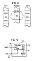
- FIG. 8 illustrates the flow graph for a procedure call.
- Figure 8 illustrates a program containing Part 1, Part 2 and Procedure.
- Part 1 has sequential blocks of instructions Block A, Block B between which is located a call instruction.
- Part 2 has sequential blocks of instructions Block C, Block D between which is a call instruction.
- the procedure includes a sequence of procedure instructions PROC and a return instruction. The two pieces of code, Part 1 and Part 2 both call the Procedure and both return to their respective control flows.
- the call instruction can be implemented as a particular type of set or do branch instruction which not only identifies a target location (SET) or branch point (D0) but causes the return address of the first instruction of the next sequential block to be saved in a return register. Then, the return instruction can be implemented as a particular type of set instruction which effects a branch to the return address which was held in the register.
- SET target location
- D0 branch point
- Figure 9 indicates the state register required to implement procedure calls.
- This includes registers 230 with a select register unit 232 controlled by a register select signal 234.
- the address of the next instruction after the call instruction to which the program is to return is stored in the registers 230 on branch line 236 responsive to the store signal 238.
- the branch is effected to the target location which is stored in the specified register 230.
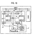
- Figure 10 illustrate in block diagram form an alternative embodiment where the instruction fetch circuit comprises two instruction fetchers, one of which is always the active fetcher. This embodiment will now more clearly be described with reference to Figure 10.
- Figure 10 illustrates a pipelined processor 17' including execution circuitry with a set branch instruction execution circuit 136' and a do branch instruction execution circuit 142'.
- the fetch circuit includes an active fetcher and a target fetcher.
- the active fetcher includes a fetch pointer 65' and an instruction buffer 66'.
- the target fetcher similarly includes a fetch pointer 65'' and a target instruction buffer 66''.
- the target pointer register 118' is initialised to instruct the fetch pointer 65'' of the target fetcher to commence fetching instructions from the target location.
- the active fetcher is fetching instructions sequentially from memory and supplying them to the processor 17'.
- a copy unit 300 acts to copy the contents of the target instruction buffer 66'' of the target fetcher to the instruction buffer 66' of the active fetcher so that the next instructions to be supplied to the processor 17' are those commencing from the target location.
Abstract
Description
| set | 〈addr〉 | ;specify branch target |
| ... | ||
| confirm | 〈cond〉 | ;confirm the branch |
| ... | ||
| do | ;execute it, if confirmed |
| set | 〈addr〉 | ;specify branch target |
| ... | ||
| reject | 〈cond〉 | ;optional conditional reject branch |
| ... | ||
| do | ;do the branch if not rejected |
| set | 〈addr〉 | ;initialize branch target |
| ... | ||
| do | 〈cond〉 | ;conditionally execute branch |
| set | 〈addr〉 | ;initialize branch target |
| ... | ||
| confirm | 〈cond〉 | ;conditionally confirm branch |
| ... | ||
| do | 〈offset〉 | ;perform branch some instruction later |
| set | 〈addr〉 | ;initialize branch target |
| ... | ||
| reject | 〈cond〉 | ;optionally conditionally reject branch |
| ... | ||
| do | 〈offset〉 | ;perform branch some instruction later |
| set | 〈offset〉,〈addr〉 | ;initialize target and branch point |
| ... | ||
| confirm | 〈cond〉 | ;conditionally confirm branch |
| set | 〈offset〉,〈addr〉 | ;initialise target and branch point |
| ... | ||
| reject | 〈cond〉 | ;optionally conditionally reject branch |
| set | 〈addr〉 | ;initialize branch target |
| ... | ||
| do | 〈cond〉,〈offset〉 | ;confirm and set branch point |
| set | loop | ;set branch target to loop |
| loop: | ;loop entry point | |
| ... | ;loop code | |
| do | 〈cond〉,〈offset〉 | ;loop continuation condition |
| ... | ;some more loop code |
Claims (19)
- A computer system for fetching, decoding and executing instructions comprising:storage circuitry (41) for holding a plurality of instructions at respective storage locations, said plurality of instructions being arranged in instruction strings, each string comprising a first instruction and a set of subsequent instructions;instruction fetch circuitry (10) for fetching a sequence of instructions from said storage circuitry (41) and including an indicator (65) for providing an indication of a next address at which a next fetch operation is to be effected;execution circuitry (18) for executing fetched instructions, wherein at least some of said instruction strings each includes,(a) a set branch instruction (SET) which provides an indication of a target location from which a subsequent instruction may be fetched, the subsequent instruction being from a different instruction string, said instruction fetch circuitry (10) being operated responsive to execution of a said set branch instruction (SET) to fetch in parallel subsequent instructions from said string containing said set branch instruction and new instructions from said different instruction string commencing from said target location while said subsequent instructions continue to be executed, and(b) an effect branch (DO) instruction;
characterised in that at least some of said instruction strings further include,(c) a condition instruction which defines a condition and determines that further instructions to be executed are new instructions only if that condition is satisfied,
and characterised by select circuitry (112,122,104) responsive to execution of the effect branch (DO) instruction to cause said execution circuitry (18) to execute said new instructions if the condition defined by the condition instruction is satisfied. - A computer system according to claim 1, wherein said instruction fetch circuitry (10) comprises two instruction buffers (66), a first buffer (66') for holding subsequent instructions connected to said execution circuitry (18), and a second buffer (66'') for holding new instructions wherein the contents of said second buffer are copied into said first buffer responsive to execution of said effect branch (DO) instruction.
- A computer system according to claim 1, wherein said instruction fetch circuitry (10) includes two instruction fetchers (Fetcher A;Fetcher B) for fetching respectively said subsequent instructions and said new instructions and wherein said select circuitry (112,122,104) is operable to connect a selected one of said instruction fetchers to said execution circuity (18).
- A computer system according to claim 3, wherein said instruction fetch circuitry (10) comprises a third instruction fetcher (Fetcher M) for fetching instructions to implement predicted conditional instructions.
- A computer system according to claim 1, 2, 3 or 4, which includes a first register (108) for holding an indication of the address from which a next instruction is to be fetched.
- A computer system according to any preceding claim, wherein a target store (65) holds the address from which the first instruction of a string of new instructions is to be fetched.
- A computer system according to any of claims 1 to 5, wherein the set branch instruction identifies a special register (118) which holds the address from which the first instruction of a string of new instructions is to be fetched.
- A computer system according to any of claims 1 to 5, wherein a target store (200) holds the address of a memory location which holds the address of the first instruction of a string of new instructions is to be fetched.
- A computer system according to any preceding claim which comprises decode circuitry (16) for decoding said fetched instructions, said instruction fetch circuitry (10) , decode circuitry (16) and execution circuitry (18) being arranged in a pipeline.
- A computer system according to any preceding claim wherein said effect branch (DO) instruction is located at the branch point after which said new instructions are to be executed.
- A computer system according to any of claims 1 to 9, wherein said effect branch (DO) instruction is located in the string prior to the branch point after which further instructions to be executed are said new instructions, said effect branch (DO) instruction indicating the branch point and wherein the computer system comprises a branch point register (120) for holding said branch point.
- A computer system according to any preceding claim which comprises a return register (230) for holding a return address being the address of the next instruction after said branch point, wherein said effect branch (DO) instruction is effective to save said return address in said return register (230) and wherein said set branch instruction identifies said return register to indicate the target location.
- A method of operating a computer to fetch decode and execute instructions which computer has storage circuitry (11) holding a plurality of instructions at respective storage locations, said plurality of instructions being arranged in instruction strings, each string comprising a first instruction and a set of subsequent instructions the method comprising:fetching a sequence of instructions from said storage circuitry (11) and providing an indication of a next address at which a next fetch operation is to be effected;decoding said instructions;executing each instruction in turn, wherein at least some of said instruction strings each include,(a) a set branch instruction (SET) which provides an indication of a target location from which a subsequent instruction may be fetched, the subsequent instruction being from a different instruction string, and(b) an effect branch instruction;on execution of said set branch instruction, holding the indication of said target location in a target store (65), fetching in parallel subsequent instructions from the string containing said branch instruction and new instructions from said different instruction string commencing from said target location,
characterised in that at least some of said instruction strings also include a condition instruction which defines a condition for a branch to be taken, and characterised by the following steps,continuing to execute said subsequent instructions until the effect branch instruction (DO) is executed which indicates that further instructions to be executed are said new instructions if the condition defined by the condition instruction is satisfied; andresponding to said effect branch instruction (DO) by commencing execution of said new instructions. - A method according to claim 13, wherein said subsequent instructions are held in a first buffer (65') and said new instructions are held in a second buffer (66'') and wherein said effect branch instruction (DO) causes the contents of said second buffer to be copied into said first buffer.
- A method according to claim 13, wherein a first instruction fetcher (Fetcher A) fetches said subsequent instructions and a second instruction fetcher (Fetcher B) fetches said new instructions, said effect branch instruction (DO) selecting which of said first and second instruction fetchers supplies instructions for execution.
- A method according to any of claims 13 to 15, wherein the set branch instruction identifies as the target location the address from which the first instruction of a string of new instructions is to be fetched.
- A method according to any of claims 13 to 15, wherein the set branch instruction identifies a special register (118) which holds the target location.
- A method according to any of claims 13 to 15, wherein the set branch instruction identifies the address of a memory location holding the target location.
- A method according to claim 13, wherein execution of said effect branch instruction causes a return address to be saved n a return register (230) and wherein said set branch instruction identifies the return register to indicate the target location.
Applications Claiming Priority (3)
| Application Number | Priority Date | Filing Date | Title |
|---|---|---|---|
| GB9412487A GB9412487D0 (en) | 1994-06-22 | 1994-06-22 | A computer system for executing branch instructions |
| GB9412487 | 1994-06-22 | ||
| EP95304199A EP0689131B1 (en) | 1994-06-22 | 1995-06-16 | A computer system for executing branch instructions |
Related Parent Applications (1)
| Application Number | Title | Priority Date | Filing Date |
|---|---|---|---|
| EP95304199.3 Division | 1995-06-16 |
Publications (3)
| Publication Number | Publication Date |
|---|---|
| EP1003095A2 true EP1003095A2 (en) | 2000-05-24 |
| EP1003095A3 EP1003095A3 (en) | 2001-02-28 |
| EP1003095B1 EP1003095B1 (en) | 2005-04-13 |
Family
ID=10757116
Family Applications (2)
| Application Number | Title | Priority Date | Filing Date |
|---|---|---|---|
| EP00102080A Expired - Lifetime EP1003095B1 (en) | 1994-06-22 | 1995-06-16 | A computer system for executing branch instructions |
| EP95304199A Expired - Lifetime EP0689131B1 (en) | 1994-06-22 | 1995-06-16 | A computer system for executing branch instructions |
Family Applications After (1)
| Application Number | Title | Priority Date | Filing Date |
|---|---|---|---|
| EP95304199A Expired - Lifetime EP0689131B1 (en) | 1994-06-22 | 1995-06-16 | A computer system for executing branch instructions |
Country Status (5)
| Country | Link |
|---|---|
| US (2) | US5961637A (en) |
| EP (2) | EP1003095B1 (en) |
| JP (1) | JP2746549B2 (en) |
| DE (2) | DE69534148T2 (en) |
| GB (1) | GB9412487D0 (en) |
Families Citing this family (50)
| Publication number | Priority date | Publication date | Assignee | Title |
|---|---|---|---|---|
| GB9412487D0 (en) * | 1994-06-22 | 1994-08-10 | Inmos Ltd | A computer system for executing branch instructions |
| KR100240591B1 (en) * | 1996-11-06 | 2000-03-02 | 김영환 | Branch target buffer for processing branch instruction efficontly and brand prediction method using thereof |
| US6157988A (en) * | 1997-08-01 | 2000-12-05 | Micron Technology, Inc. | Method and apparatus for high performance branching in pipelined microsystems |
| US6467035B2 (en) * | 1997-09-08 | 2002-10-15 | Agere Systems Guardian Corp. | System and method for performing table look-ups using a multiple data fetch architecture |
| JP3741870B2 (en) * | 1998-08-07 | 2006-02-01 | 富士通株式会社 | Instruction and data prefetching method, microcontroller, pseudo instruction detection circuit |
| US6611910B2 (en) * | 1998-10-12 | 2003-08-26 | Idea Corporation | Method for processing branch operations |
| US6233676B1 (en) * | 1999-03-18 | 2001-05-15 | Ip-First, L.L.C. | Apparatus and method for fast forward branch |
| JP3606435B2 (en) * | 1999-09-29 | 2005-01-05 | 富士通株式会社 | Instruction processing apparatus and method for controlling branch instruction to change mode |
| US6912650B2 (en) * | 2000-03-21 | 2005-06-28 | Fujitsu Limited | Pre-prefetching target of following branch instruction based on past history |
| US6446197B1 (en) | 1999-10-01 | 2002-09-03 | Hitachi, Ltd. | Two modes for executing branch instructions of different lengths and use of branch control instruction and register set loaded with target instructions |
| US6772325B1 (en) * | 1999-10-01 | 2004-08-03 | Hitachi, Ltd. | Processor architecture and operation for exploiting improved branch control instruction |
| US6820193B1 (en) * | 1999-12-17 | 2004-11-16 | Koninklijke Philips Electronics N.V. | Branch instructions with decoupled condition and address |
| US6604191B1 (en) * | 2000-02-04 | 2003-08-05 | International Business Machines Corporation | Method and apparatus for accelerating instruction fetching for a processor |
| US7085915B1 (en) * | 2000-02-29 | 2006-08-01 | International Business Machines Corporation | Programmable prefetching of instructions for a processor executing a non-procedural program |
| GB0025053D0 (en) | 2000-10-12 | 2000-11-29 | Sgs Thomson Microelectronics | Compiling computer programs including branch instructions |
| GB0025052D0 (en) | 2000-10-12 | 2000-11-29 | Sgs Thomson Microelectronics | Compiling computer programs including branch instructions |
| FR2821450B1 (en) * | 2001-02-27 | 2004-07-09 | St Microelectronics Sa | METHOD FOR MANAGING CONNECTION INSTRUCTIONS WITHIN A PROCESSOR, IN PARTICULAR A DIGITAL SIGNAL PROCESSING PROCESSOR, AND CORRESPONDING PROCESSOR |
| JP3804941B2 (en) * | 2002-06-28 | 2006-08-02 | 富士通株式会社 | Instruction fetch control device |
| DE10254653B4 (en) * | 2002-11-22 | 2009-05-28 | Infineon Technologies Ag | Device for controlling the processing of data words of a data stream |
| US20050055544A1 (en) * | 2003-07-30 | 2005-03-10 | International Business Machines Corporation | Central processing unit having a module for processing of function calls |
| JP2005078234A (en) * | 2003-08-29 | 2005-03-24 | Renesas Technology Corp | Information processor |
| GB2409064B (en) * | 2003-12-09 | 2006-09-13 | Advanced Risc Mach Ltd | A data processing apparatus and method for performing in parallel a data processing operation on data elements |
| GB2409063B (en) * | 2003-12-09 | 2006-07-12 | Advanced Risc Mach Ltd | Vector by scalar operations |
| GB2409068A (en) * | 2003-12-09 | 2005-06-15 | Advanced Risc Mach Ltd | Data element size control within parallel lanes of processing |
| GB2409065B (en) * | 2003-12-09 | 2006-10-25 | Advanced Risc Mach Ltd | Multiplexing operations in SIMD processing |
| GB2409061B (en) * | 2003-12-09 | 2006-09-13 | Advanced Risc Mach Ltd | Table lookup operation within a data processing system |
| GB2409060B (en) * | 2003-12-09 | 2006-08-09 | Advanced Risc Mach Ltd | Moving data between registers of different register data stores |
| GB2409066B (en) * | 2003-12-09 | 2006-09-27 | Advanced Risc Mach Ltd | A data processing apparatus and method for moving data between registers and memory |
| GB2409059B (en) * | 2003-12-09 | 2006-09-27 | Advanced Risc Mach Ltd | A data processing apparatus and method for moving data between registers and memory |
| GB2411974C (en) * | 2003-12-09 | 2009-09-23 | Advanced Risc Mach Ltd | Data shift operations |
| GB2409062C (en) * | 2003-12-09 | 2007-12-11 | Advanced Risc Mach Ltd | Aliasing data processing registers |
| GB2411975B (en) * | 2003-12-09 | 2006-10-04 | Advanced Risc Mach Ltd | Data processing apparatus and method for performing arithmetic operations in SIMD data processing |
| GB2411973B (en) * | 2003-12-09 | 2006-09-27 | Advanced Risc Mach Ltd | Constant generation in SMD processing |
| GB2411976B (en) * | 2003-12-09 | 2006-07-19 | Advanced Risc Mach Ltd | A data processing apparatus and method for moving data between registers and memory |
| GB2409067B (en) * | 2003-12-09 | 2006-12-13 | Advanced Risc Mach Ltd | Endianess compensation within a SIMD data processing system |
| GB2410097B (en) * | 2004-01-13 | 2006-11-01 | Advanced Risc Mach Ltd | A data processing apparatus and method for performing data processing operations on floating point data elements |
| GB2411978B (en) * | 2004-03-10 | 2007-04-04 | Advanced Risc Mach Ltd | Inserting bits within a data word |
| US20050223202A1 (en) * | 2004-03-31 | 2005-10-06 | Intel Corporation | Branch prediction in a pipelined processor |
| US20050257035A1 (en) * | 2004-05-12 | 2005-11-17 | International Business Machines Corporation | Linked instruction buffering of basic blocks for asynchronous predicted taken branches |
| JP3760999B2 (en) * | 2004-06-15 | 2006-03-29 | セイコーエプソン株式会社 | Information processing apparatus, microcomputer and electronic device |
| US9557994B2 (en) | 2004-07-13 | 2017-01-31 | Arm Limited | Data processing apparatus and method for performing N-way interleaving and de-interleaving operations where N is an odd plural number |
| US8046569B2 (en) * | 2007-04-30 | 2011-10-25 | Hewlett-Packard Development Company, L.P. | Processing element having dual control stores to minimize branch latency |
| US20090276537A1 (en) * | 2007-12-20 | 2009-11-05 | Deverick James W | Mechanisms for role negotiation in the establishment of secure communication channels in peer-to-peer environments |
| US8671202B2 (en) | 2007-12-20 | 2014-03-11 | Ooma, Inc. | Mechanisms for role negotiation in the establishment of secure communication channels in peer-to-peer environments |
| US9952869B2 (en) * | 2009-11-04 | 2018-04-24 | Ceva D.S.P. Ltd. | System and method for using a branch mis-prediction buffer |
| US20130305017A1 (en) * | 2012-05-08 | 2013-11-14 | Alexander Rabinovitch | Compiled control code parallelization by hardware treatment of data dependency |
| US9535701B2 (en) * | 2014-01-29 | 2017-01-03 | Telefonaktiebolaget Lm Ericsson (Publ) | Efficient use of branch delay slots and branch prediction in pipelined computer architectures |
| US9430245B2 (en) | 2014-03-28 | 2016-08-30 | Telefonaktiebolaget Lm Ericsson (Publ) | Efficient branch predictor history recovery in pipelined computer architectures employing branch prediction and branch delay slots of variable size |
| GB2551548B (en) | 2016-06-22 | 2019-05-08 | Advanced Risc Mach Ltd | Register restoring branch instruction |
| JP6374454B2 (en) * | 2016-08-08 | 2018-08-15 | 株式会社Dnpハイパーテック | Module encryption / decryption program |
Citations (4)
| Publication number | Priority date | Publication date | Assignee | Title |
|---|---|---|---|---|
| US3551895A (en) * | 1968-01-15 | 1970-12-29 | Ibm | Look-ahead branch detection system |
| US3577189A (en) * | 1969-01-15 | 1971-05-04 | Ibm | Apparatus and method in a digital computer for allowing improved program branching with branch anticipation reduction of the number of branches, and reduction of branch delays |
| US4200927A (en) * | 1978-01-03 | 1980-04-29 | International Business Machines Corporation | Multi-instruction stream branch processing mechanism |
| EP0355069A2 (en) * | 1988-08-15 | 1990-02-21 | EVANS & SUTHERLAND COMPUTER CORPORATION | Variable delay branch system |
Family Cites Families (6)
| Publication number | Priority date | Publication date | Assignee | Title |
|---|---|---|---|---|
| US3426330A (en) * | 1966-02-14 | 1969-02-04 | Burroughs Corp | Central data processor |
| US3573854A (en) * | 1968-12-04 | 1971-04-06 | Texas Instruments Inc | Look-ahead control for operation of program loops |
| US4742451A (en) * | 1984-05-21 | 1988-05-03 | Digital Equipment Corporation | Instruction prefetch system for conditional branch instruction for central processor unit |
| US4777587A (en) * | 1985-08-30 | 1988-10-11 | Advanced Micro Devices, Inc. | System for processing single-cycle branch instruction in a pipeline having relative, absolute, indirect and trap addresses |
| DE4345028A1 (en) * | 1993-05-06 | 1994-11-10 | Hewlett Packard Co | Device for reducing delays due to branching |
| GB9412487D0 (en) * | 1994-06-22 | 1994-08-10 | Inmos Ltd | A computer system for executing branch instructions |
-
1994
- 1994-06-22 GB GB9412487A patent/GB9412487D0/en active Pending
-
1995
- 1995-06-16 EP EP00102080A patent/EP1003095B1/en not_active Expired - Lifetime
- 1995-06-16 DE DE69534148T patent/DE69534148T2/en not_active Expired - Fee Related
- 1995-06-16 DE DE69522385T patent/DE69522385D1/en not_active Expired - Lifetime
- 1995-06-16 EP EP95304199A patent/EP0689131B1/en not_active Expired - Lifetime
- 1995-06-21 US US08/493,103 patent/US5961637A/en not_active Expired - Lifetime
- 1995-06-22 JP JP7179312A patent/JP2746549B2/en not_active Expired - Fee Related
-
2001
- 2001-04-25 US US09/842,312 patent/US7047399B2/en not_active Expired - Fee Related
Patent Citations (4)
| Publication number | Priority date | Publication date | Assignee | Title |
|---|---|---|---|---|
| US3551895A (en) * | 1968-01-15 | 1970-12-29 | Ibm | Look-ahead branch detection system |
| US3577189A (en) * | 1969-01-15 | 1971-05-04 | Ibm | Apparatus and method in a digital computer for allowing improved program branching with branch anticipation reduction of the number of branches, and reduction of branch delays |
| US4200927A (en) * | 1978-01-03 | 1980-04-29 | International Business Machines Corporation | Multi-instruction stream branch processing mechanism |
| EP0355069A2 (en) * | 1988-08-15 | 1990-02-21 | EVANS & SUTHERLAND COMPUTER CORPORATION | Variable delay branch system |
Non-Patent Citations (5)
| Title |
|---|
| "ACCELERATION OF MULTIMEDIA APPLICATIONS USING BRANCH CONDITIONAL TO PREVIOUS TARGET INSTRUCTION" IBM TECHNICAL DISCLOSURE BULLETIN,US,IBM CORP. NEW YORK, vol. 37, no. 4B, 1 April 1994 (1994-04-01), pages 285-288, XP000451255 ISSN: 0018-8689 * |
| BEEBE ET AL.: "Instruction sequencing control" IBM TECHNICAL DISCLOSURE BULLETIN., vol. 14, no. 12, May 1972 (1972-05), pages 3599-3611, XP002155741 NEW YORK US * |
| CORTADELLA AND LLABERIA: "Making branches transparent to the execution unit" INTERNATIONAL JOURNAL OF MINI AND MICROCOMPUTERS, vol. 11, no. 1, - 1989 pages 13-17, XP000210082 CALGARY, CALIFORNIA US * |
| LEE R ET AL: "PATHLENGTH REDUCTION FEATURES IN THE PA-RISC ARCHITECTURE" PROCEEDINGS OF THE COMPUTER SOCIETY INTERNATIONAL CONFERENCE (COMPCON)SPRING,US,LOS ALAMITOS, IEEE COMP. SOC. PRESS, vol. CONF. 37, 24 - 28 February 1992, pages 129-135, XP000340724 ISBN: 0-8186-2655-0 * |
| PLESZKUN AND FARRENS: "An instruction cache design for use with a delayed branch" PROCEEDINGS 4TH MIT CONFERENCE : ADVANCED RESEARCH IN VLSI, 7 April 1986 (1986-04-07), pages 73-88, XP002155740 CAMBRIDGE, MA,US * |
Also Published As
| Publication number | Publication date |
|---|---|
| DE69522385D1 (en) | 2001-10-04 |
| US5961637A (en) | 1999-10-05 |
| JPH0844562A (en) | 1996-02-16 |
| JP2746549B2 (en) | 1998-05-06 |
| DE69534148T2 (en) | 2006-02-16 |
| EP1003095B1 (en) | 2005-04-13 |
| DE69534148D1 (en) | 2005-05-19 |
| US20020078330A1 (en) | 2002-06-20 |
| EP0689131A1 (en) | 1995-12-27 |
| US7047399B2 (en) | 2006-05-16 |
| EP1003095A3 (en) | 2001-02-28 |
| GB9412487D0 (en) | 1994-08-10 |
| EP0689131B1 (en) | 2001-08-29 |
Similar Documents
| Publication | Publication Date | Title |
|---|---|---|
| EP0689131B1 (en) | A computer system for executing branch instructions | |
| US4476525A (en) | Pipeline-controlled data processing system capable of performing a plurality of instructions simultaneously | |
| EP0134620B1 (en) | Data processing apparatus and method | |
| US5136696A (en) | High-performance pipelined central processor for predicting the occurrence of executing single-cycle instructions and multicycle instructions | |
| US5809294A (en) | Parallel processing unit which processes branch instructions without decreased performance when a branch is taken | |
| US5421020A (en) | Counter register implementation for speculative execution of branch on count instructions | |
| JP2744890B2 (en) | Branch prediction data processing apparatus and operation method | |
| JP2937485B2 (en) | Method and apparatus for detecting and executing traps in a superscalar processor | |
| EP0135844A2 (en) | A data processor with a branch target instruction storage | |
| JPH0334024A (en) | Method of branch prediction and instrument for the same | |
| EP1122639A2 (en) | Mechanism for load block on store address generation and universal dependency vector/queue entry | |
| US5522084A (en) | Method and system for invalidating instructions utilizing validity and write delay flags in parallel processing apparatus | |
| US5469552A (en) | Pipelined data processor having combined operand fetch and execution stage to reduce number of pipeline stages and penalty associated with branch instructions | |
| JP2006522398A (en) | Using bypass in pipelined instruction processors | |
| US5461715A (en) | Data processor capable of execution of plural instructions in parallel | |
| US5666507A (en) | Pipelined microinstruction apparatus and methods with branch prediction and speculative state changing | |
| EP0550289A2 (en) | A mechanism to detect stores into the instruction stream | |
| JPH0743648B2 (en) | Information processing equipment | |
| US5745723A (en) | Data processing system capable of execution of plural instructions in parallel | |
| US6360310B1 (en) | Apparatus and method for instruction cache access | |
| KR970011209B1 (en) | Microprocessor including circuit for generating signal used for tracing executed instruction stream | |
| JPH07262006A (en) | Data processor with branch target address cache | |
| JP3493110B2 (en) | High-speed branch processing unit | |
| JPH0773034A (en) | Information processor | |
| JP2591325B2 (en) | Branch control device |
Legal Events
| Date | Code | Title | Description |
|---|---|---|---|
| PUAI | Public reference made under article 153(3) epc to a published international application that has entered the european phase |
Free format text: ORIGINAL CODE: 0009012 |
|
| 17P | Request for examination filed |
Effective date: 20000202 |
|
| AC | Divisional application: reference to earlier application |
Ref document number: 689131 Country of ref document: EP |
|
| AK | Designated contracting states |
Kind code of ref document: A2 Designated state(s): DE FR GB IT |
|
| PUAL | Search report despatched |
Free format text: ORIGINAL CODE: 0009013 |
|
| AK | Designated contracting states |
Kind code of ref document: A3 Designated state(s): DE FR GB IT |
|
| AKX | Designation fees paid |
Free format text: DE FR GB IT |
|
| 17Q | First examination report despatched |
Effective date: 20030528 |
|
| GRAP | Despatch of communication of intention to grant a patent |
Free format text: ORIGINAL CODE: EPIDOSNIGR1 |
|
| GRAS | Grant fee paid |
Free format text: ORIGINAL CODE: EPIDOSNIGR3 |
|
| GRAA | (expected) grant |
Free format text: ORIGINAL CODE: 0009210 |
|
| AC | Divisional application: reference to earlier application |
Ref document number: 0689131 Country of ref document: EP Kind code of ref document: P |
|
| AK | Designated contracting states |
Kind code of ref document: B1 Designated state(s): DE FR GB IT |
|
| REG | Reference to a national code |
Ref country code: GB Ref legal event code: FG4D |
|
| REF | Corresponds to: |
Ref document number: 69534148 Country of ref document: DE Date of ref document: 20050519 Kind code of ref document: P |
|
| PGFP | Annual fee paid to national office [announced via postgrant information from national office to epo] |
Ref country code: FR Payment date: 20050608 Year of fee payment: 11 |
|
| PGFP | Annual fee paid to national office [announced via postgrant information from national office to epo] |
Ref country code: DE Payment date: 20050609 Year of fee payment: 11 |
|
| PGFP | Annual fee paid to national office [announced via postgrant information from national office to epo] |
Ref country code: GB Payment date: 20050615 Year of fee payment: 11 |
|
| PLBE | No opposition filed within time limit |
Free format text: ORIGINAL CODE: 0009261 |
|
| STAA | Information on the status of an ep patent application or granted ep patent |
Free format text: STATUS: NO OPPOSITION FILED WITHIN TIME LIMIT |
|
| ET | Fr: translation filed | ||
| 26N | No opposition filed |
Effective date: 20060116 |
|
| PG25 | Lapsed in a contracting state [announced via postgrant information from national office to epo] |
Ref country code: GB Free format text: LAPSE BECAUSE OF NON-PAYMENT OF DUE FEES Effective date: 20060616 |
|
| PGFP | Annual fee paid to national office [announced via postgrant information from national office to epo] |
Ref country code: IT Payment date: 20060630 Year of fee payment: 12 |
|
| PG25 | Lapsed in a contracting state [announced via postgrant information from national office to epo] |
Ref country code: DE Free format text: LAPSE BECAUSE OF NON-PAYMENT OF DUE FEES Effective date: 20070103 |
|
| GBPC | Gb: european patent ceased through non-payment of renewal fee |
Effective date: 20060616 |
|
| REG | Reference to a national code |
Ref country code: FR Ref legal event code: ST Effective date: 20070228 |
|
| PG25 | Lapsed in a contracting state [announced via postgrant information from national office to epo] |
Ref country code: FR Free format text: LAPSE BECAUSE OF NON-PAYMENT OF DUE FEES Effective date: 20060630 |
|
| PG25 | Lapsed in a contracting state [announced via postgrant information from national office to epo] |
Ref country code: IT Free format text: LAPSE BECAUSE OF NON-PAYMENT OF DUE FEES Effective date: 20070616 |