EP1004848A1 - Angular velocity sensor - Google Patents
Angular velocity sensor Download PDFInfo
- Publication number
- EP1004848A1 EP1004848A1 EP99924018A EP99924018A EP1004848A1 EP 1004848 A1 EP1004848 A1 EP 1004848A1 EP 99924018 A EP99924018 A EP 99924018A EP 99924018 A EP99924018 A EP 99924018A EP 1004848 A1 EP1004848 A1 EP 1004848A1
- Authority
- EP
- European Patent Office
- Prior art keywords
- circuit
- output signal
- detecting
- reference voltage
- generating means
- Prior art date
- Legal status (The legal status is an assumption and is not a legal conclusion. Google has not performed a legal analysis and makes no representation as to the accuracy of the status listed.)
- Granted
Links
Images

Classifications
-
- G—PHYSICS
- G01—MEASURING; TESTING
- G01C—MEASURING DISTANCES, LEVELS OR BEARINGS; SURVEYING; NAVIGATION; GYROSCOPIC INSTRUMENTS; PHOTOGRAMMETRY OR VIDEOGRAMMETRY
- G01C19/00—Gyroscopes; Turn-sensitive devices using vibrating masses; Turn-sensitive devices without moving masses; Measuring angular rate using gyroscopic effects
- G01C19/56—Turn-sensitive devices using vibrating masses, e.g. vibratory angular rate sensors based on Coriolis forces
- G01C19/5607—Turn-sensitive devices using vibrating masses, e.g. vibratory angular rate sensors based on Coriolis forces using vibrating tuning forks
Landscapes
- Physics & Mathematics (AREA)
- Engineering & Computer Science (AREA)
- General Physics & Mathematics (AREA)
- Radar, Positioning & Navigation (AREA)
- Remote Sensing (AREA)
- Gyroscopes (AREA)
Abstract
Description
- The present invention relates to an angular rate sensor.
- Fig. 3 shows an example of angular rate sensors proposed in the past. In Fig. 3, a
support pin 101 made of metal is press-fitted perpendicularly and secured in a weight plate (not shown in the figure), and one end of anothersupport pin 102 also made of metal is press-fitted and secured in thesupport pin 101 in an orthogonal direction to it. Ablock 103 made of metal is fixed by soldering at the other end of thesupport pin 102, which also serves as a common terminal.Vibration plates metal block 103. Apiezoelectric element 106 is bonded on thevibration plate 104 to constitute a vibration exciter 150, and anotherpiezoelectric element 107 is bonded on thevibration plate 105 to constitute a means 160 for detecting a level of vibrations. A tip of thevibration plate 104 is extended in a manner to form a right angle with thepiezoelectric element 106 to become a detecting plate 108. A tip of thevibration plate 105 is also extended in the same manner to form a right angle with thepiezoelectric element 107 to become anotherdetecting plate 109.Piezoelectric elements 110 and 111 are bonded respectively on the detectingplates 108 and 109, to constitutedetecting means element unit 112 of a tuning-fork type angular rate sensor. - A structure of Fig. 3 further comprises;
- (a) a
current amplifier circuit 120 for amplifying an output signal from thepiezoelectric element 107 provided on thevibration plate 105 to detect a level of vibrations of thevibration plate 105, which vibrates in a tuning-fork phenomenon in concert with vibrations of thevibration plate 104; - (b) a full-
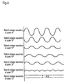
wave rectifier circuit 122 for producing a D.C. voltage by rectifying an output signal (i.e. a signal at a point "A", of which a signal voltage waveform is shown in Fig. 4) of a band-pass filter circuit (hereinafter referred to as "BPF circuit") 121, wherein an output signal of thecurrent amplifier circuit 120 is input; - (c) an automatic gain control circuit (hereinafter referred to as "AGC") 123
whose amplification factor for the output signal of the
BPF circuit 121 varies according to a magnitude of an output signal of the full-wave rectifier circuit 122; - (d) a driver circuit 124 (an output signal of this circuit, i.e. a signal at a
point "B", has a voltage waveform shown in Fig. 4) for driving the
piezoelectric element 106 bonded on thevibration plate 104 according to a magnitude of an output signal of theAGC 123; - (e) a
charge amplifier circuit 125 for inputting and amplifying output signals of thepiezoelectric elements 110 and 111, which detect a Coriolis' force generated in proportion to an angular rate; - (f) a
synchronous detection circuit 127 for detecting an output signal of aBPF circuit 126, wherein an output signal of thecharge amplifier circuit 125 is input; and - (g) a
sensor output terminal 129 for outputting an output signal of a low-pass filter circuit (hereinafter referred to as "LPF circuit") 128, wherein an output signal of thesynchronous detection circuit 127 is input. -
- In addition, a reference voltage generating means 132 comprises a
power supply 130 and abuffer 131. The reference voltage generating means 132 supplies a reference voltage to each of the above-cited circuits through a circuit resistance 133 (let a resistance value be "R1"). - A
terminal 135 is also provided for connecting the reference voltage generating means 132 to thesupport pin 102 via thecircuit resistance 133 and another circuit resistance 134 (let a resistance value be "R2"). The foregoing elements constitute adriving circuit 136. - The
element unit 112 of a tuning-fork type angular rate sensor and thedriving circuit 136 complete the angular rate sensor. - In the prior art technique, an alternate current "i" flows from the
driver circuit 124 toward the reference voltage generating means 132 via theterminal 135 by passing through the vibration exciter 150 at all the time, even in an ordinary vibrating condition of the tuning fork. - In addition, a demand for reduction in size of the angular rate sensors necessitates an integration of the
driving circuit 136 into an IC tip form. This consequently reduces a width of wiring pattern, which in turn increases resistance values of theindividual circuit resistances - Ripple voltage of a large magnitude defined by
circuit resistances 133 and 134 (this ripple voltage is observed at a point "C", and a waveform of the signal voltage is shown in Fig. 4). - The ripple voltage subsequently causes a substantial difference between the reference voltage input to individual circuits and the voltage at the
terminal 135. A displacement current flows as a result (this displacement current is observed at a point "D", of which a signal current waveform is shown in Fig. 4) from thepiezoelectric elements 110 and 111. This displacement current is input in thecharge amplifier circuit 125, and an output signal voltage of it appears at a point "E" (a waveform of the signal voltage is shown in Fig. 4). However, this signal voltage turns into an output signal of thesynchronous detection circuit 127 and appears at a point "F" (a waveform of this signal voltage is shown in Fig. 4) without being cut off in a process of synchronous detection, since it is in a same phase as the waveform of the signal voltage at the point "A", i.e. a timing signal, of thesynchronous detection circuit 127. This output signal eventually becomes an offset voltage (this offset voltage is observed at a point "G", as shown in Fig. 4), and it comes out at theoutput terminal 129. This offset voltage denoted as ΔV is given by a formula (1): - A is a gain of the low-pass filter and the band-pass filter;
- D is a detection coefficient;
- C0 is a feedback capacity of the charge amplifier, in pF; and
- Cs1 and Cs2 are electrostatic capacities of the
piezoelectric elements 110 and 111, in pF. -
- In addition, it is likely that a variation occurs with the reference voltage input to the individual circuits, since ripple voltage of a large magnitude defined by R1 · i is generated in the
circuit resistance 133. - The present invention is intended to solve the above problem, and to provide an angular rate sensor that is capable of restraining an output voltage of a sensor from being offset, by way of suppressing a current flowing in and out of a common terminal so as not to allow it to flow in and out of a side of a reference voltage generating means.
- In order to solve the foregoing problem, the angular rate sensor of the present invention comprises:
- (a) a vibration exciter for providing a vibration body with vibrations;
- (b) a means for detecting a level of vibrations of the vibration body;
- (c) a detecting means for detecting a Coriolis' force produced in proportion to an angular rate;
- (d) a current amplifier circuit for amplifying an output signal of the means of detecting a level of vibrations;
- (e) a full-wave rectifier circuit for producing a D.C. voltage by rectifying an output signal of a band-pass filter circuit, wherein an output signal of the current amplifier circuit is input;
- (f) an automatic gain control circuit whose amplification factor for the output signal of the band-pass filter circuit varies according to a magnitude of an output signal of the full-wave rectifier circuit;
- (g) a driver circuit for driving the vibration exciter in accordance with a magnitude of an output signal of the automatic gain control circuit;
- (h) a charge amplifier circuit for inputting and amplifying a signal detected by the detecting means for detecting a Coriolis' force;
- (i) a synchronous detection circuit for detecting an output signal of a bandpass filter circuit, wherein an output signal of the charge amplifier circuit is input;
- (j) a sensor output terminal for outputting an output signal of a low-pass filter circuit, wherein an output signal of the synchronous detection circuit is input;
- (k) the reference voltage generating means; and
- (l) a buffer provided between the reference voltage generating means and the common terminal for the vibration exciter, the means for detecting a level of vibrations and the detecting means for detecting a Coriolis' force, for suppressing a current flowing in and out of the common terminal so as to avoid it from flowing in and out of a side of the reference voltage generating means. This structure can realize the angular rate sensor capable of restraining the output voltage of the sensor from being offset.
-
-
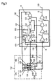
- Fig. 1 is a block diagram depicting an exemplary embodiment of an angular rate sensor of the present invention;
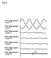
- Fig. 2 is a graphical representation of signal waveforms at various points in the same angular rate sensor;
- Fig. 3 is a block diagram depicting an angular rate sensor of the prior art; and
- Fig. 4 is a graphical representation of signal waveforms at various points in the same angular rate sensor.
-
- A first exemplary embodiment of the present invention will be described hereinafter by referring to Fig. 1 and Fig. 2.
- Fig. 1 is a block diagram depicting the first exemplary embodiment of an angular rate sensor of the present invention. Fig. 2 is a graphical representation of signal waveforms at various points shown in Fig. 1.
- In Fig. 1, a support pin 1 made of metal is press-fitted perpendicularly and secured in a weight plate (not shown in the figure), and one end of another support pin 2 also made of metal is press-fitted and secured in the support pin 1 in an orthogonal direction to it. A
block 3 made of metal is fixed to the other end of the support pin 2 by soldering. Vibration plates 4 and 5 are fixed to both ends of themetal block 3. A piezoelectric element 6 is bonded on the vibration plate 4 to constitute avibration exciter 50, and another piezoelectric element 7 is bonded on the vibration plate 5 to constitute a means 60 for detecting a level of vibrations. A tip of the vibration plate 4 is extended in a manner to form a right angle with the piezoelectric element 6 to become a detecting plate 8. A tip of the vibrating plate 5 is also extended in a manner to form a right angle with the piezoelectric element 7 to become another detectingplate 9. Piezoelectric elements 10 and 11 are bonded respectively on the detectingplates 8 and 9, to constitute detectingmeans 70 and 80 for detecting a Coriolis' force generated in proportion to an angular rate. Anelement unit 12 of a tuning-fork type angular rate sensor is completed by having the above components. - A structure of Fig. 1 further comprises;
- (a) a
current amplifier circuit 20 for amplifying an output signal from the piezoelectric element 7 provided on the vibration plate 5 to detect a level of vibrations of the vibration plate 5, which vibrates in a timing-fork phenomenon in concert with vibrations of the vibration plate 4; - (b) a full-
wave rectifier circuit 22 for producing a D.C. voltage by rectifying an output signal (i.e. a signal at a point "H" whose signal voltage waveform is shown in Fig. 2) of a band-pass filter circuit (hereinafter referred to as "BPF circuit") 21, wherein an output signal of thecurrent amplifier circuit 20 is input; - (c) an automatic gain control circuit (hereinafter referred to as "AGC") 23
whose amplification factor for the output signal of the
BPF circuit 21 varies according to a magnitude of an output signal of the full-wave rectifier circuit 22; - (d) a
driver circuit 24 for driving the piezoelectric element 6 bonded on the vibration plate 4 according to a magnitude of an output signal of the AGC 23 (an output signal of the driver circuit, i.e. a signal at a point "I" has a voltage waveform shown in Fig. 2); - (e) a
charge amplifier circuit 25 for inputting and amplifying output signals of the piezoelectric elements 10 and 11, which detect a Coriolis' force generated in proportion to an angular rate; - (f) a
synchronous detection circuit 27 for detecting an output signal of aBPF circuit 26, wherein an output signal of thecharge amplifier 25 is input; and - (g) a
sensor output terminal 29 for outputting an output signal of a low-pass filter circuit (hereinafter referred to as "LPF circuit") 28, wherein an output signal of thesynchronous detection circuit 27 is input. -
- In addition, the structure also includes a reference voltage generating means 32 comprising a
power supply 30 and abuffer 31. The reference voltage generating means 32 supplies a reference voltage to each of the above-cited circuits through a circuit resistance 33 (let a resistance value be "R3"). Afundamental driving circuit 35 is completed by having the foregoing elements. - Furthermore, a
buffer 37 is provided along a connection from the reference voltage generating means 32 in thefundamental driving circuit 35 via thecircuit resistance 33, a circuit resistance 34 (let a resistance value be "R4") and a terminal 36 to the support pin 2. The angular rate sensor is completed by including all of the above elements. - The
buffer 37 prevents a current flowing in and out of the support pin 2, which serves as a common terminal for thevibration exciter 50, the means 60 for detecting a level of vibrations, and the detectingmeans 70 and 80 for detecting a Coriolis' force, from flowing in and out of a side of the reference voltage generating means 32. - Therefore, ripple voltage defined by
circuit resistances 33 and 34 (this tipple voltage is observed at a point "J", and a signal voltage waveform of it is shown in Fig. 2). Consequently, only a slight potential difference occurs between the reference voltage input to the individual circuits and the voltage at the support pin 2, thereby resulting in a minute amount of displacement current (this displacement current is observed at a point "K", of which a signal current waveform is shown in Fig. 2) from the piezoelectric elements 10 and 11. - Accordingly, an output signal voltage (Fig. 2 shows a waveform of this output signal voltage, i.e. an output signal at a point "L") from the
charge amplifier circuit 25 is also reduced. Hence, respective output signal voltages of the succeedingsynchronous detection circuit 27 and the LPF circuit 28 (waveforms of these output signal voltages, i.e. output signals at points "M" and "N" are shown in Fig. 2) are also reduced equally. In other words, an offset voltage ΔV becomes extremely small in the end. - Moreover, a piezoelectric ripple defined by R3 · i, as produced in a portion across the
circuit resistance 33, also becomes very small, thereby stabilizing the reference voltage input to the individual circuits, and improving operational stability of the circuits. - In the first exemplary embodiment, although what has been described is an example in that the reference voltage is supplied to the individual circuits from a connecting point between the
circuit resistances circuit resistance 34, since a current flowing through thecircuit resistances - Although what has been described in the first exemplary embodiment is the structure having the buffer provided between the reference voltage generating means for supplying the reference voltage to the individual circuits and the support pin serving as the common terminal, the buffer can be provided between an independent reference voltage generating means prepared for an exclusive use and the support pin serving as the common terminal.
- Again, although what has been described in the first exemplary embodiment is only an example in that the element unit of a tuning-fork type angular rate sensor has the structure of the piezoelectric element mounted on the vibration plate, this is not necessarily restrictive. It can be a tuning-fork type vibrating body composed of single-crystal piezoelectric material, poly-crystal piezoelectric material and so on. Furthermore, a vibrating body needs not be limited to the type having a tuning-fork structure of the prior art.
- As described above, the present invention provides an angular rate sensor that is capable of restraining an output voltage of the sensor from being offset. This can be achieved by providing a buffer between a reference voltage generating means and a common terminal of a vibration exciter, a means for detecting a level of vibrations and a detecting means for detecting a Coriolis' force, for suppressing a current flowing in and out of the common terminal so as to prevent it from flowing in and out of a side of the reference voltage generating means.
-
- 2 Sopport pin
- 12 Element unit of a tuning-fork type angular rate sensor
- 20 Current amplifier circuit
- 21, 26 Band-pass filter circuit
- 22 Full-wave rectifier circuit
- 23 Automatic gain control circuit
- 24 Driver circuit
- 25 Charge amplifier circuit
- 27 Synchronous detection circuit
- 28 Low-pass filter circuit
- 29 Sensor output terminal
- 30 Power supply
- 31, 37 Buffer
- 32 Reference voltage generating means
- 33, 34 Circuit resistance
- 35 Fundamental driving circuit
- 36 Terminal
- 50 Vibration exciter
- 60 Means for detecting a level of vibrations
- 70, 80 Detecting means for detecting a Coriolis' force
-
Claims (2)
- An angular rate sensor comprising:(a) a vibration exciter for providing a vibration body with vibrations;(b) a means for detecting a level of vibrations of said vibration body;(c) a detecting means for detecting a Coriolis' force produced in proportion to an angular rate;(d) a current amplifier circuit for amplifying an output signal of said means for detecting a level of vibrations;(e) a full-wave rectifier circuit for producing a D.C. voltage by rectifying an output signal of a band-pass filter circuit, wherein an output signal of said current amplifier circuit is input;(f) an automatic gain control circuit whose amplification factor for the output signal of said band-pass filter circuit varies according to a magnitude of an output signal of said full-wave rectifier circuit;(g) a driver circuit for driving said vibration exciter according to a magnitude of an output signal of said automatic gain control circuit;(h) a charge amplifier circuit for inputting and amplifying a signal detected by said detecting means for detecting a Coriolis' force;(i) a synchronous detection circuit for detecting an output signal of a band-pass filter circuit, wherein an output signal of said charge amplifier circuit is input;(j) a sensor output terminal for outputting an output signal of a low-pass filter circuit, wherein an output signal of said synchronous detection circuit is input;(k) a reference voltage generating means; and(l) a buffer provided between said reference voltage generating means and a common terminal for said vibration exciter, said means for detecting a level of vibrations and said detecting means for detecting a Coriolis' force, for suppressing a current flowing in and out of said common terminal so as to prevent the current from flowing in and out of a side of said reference voltage generating means.
- The angular rate sensor according to claim 1, wherein a reference voltage input to said buffer is an output voltage of said reference voltage generating means for supplying a reference voltage to each of said circuits.
Applications Claiming Priority (3)
| Application Number | Priority Date | Filing Date | Title |
|---|---|---|---|
| JP16787398A JP3937589B2 (en) | 1998-06-16 | 1998-06-16 | Angular velocity sensor |
| JP16787398 | 1998-06-16 | ||
| PCT/JP1999/003151 WO1999066288A1 (en) | 1998-06-16 | 1999-06-11 | Angular velocity sensor |
Publications (3)
| Publication Number | Publication Date |
|---|---|
| EP1004848A1 true EP1004848A1 (en) | 2000-05-31 |
| EP1004848A4 EP1004848A4 (en) | 2004-12-01 |
| EP1004848B1 EP1004848B1 (en) | 2006-08-16 |
Family
ID=15857669
Family Applications (1)
| Application Number | Title | Priority Date | Filing Date |
|---|---|---|---|
| EP99924018A Expired - Lifetime EP1004848B1 (en) | 1998-06-16 | 1999-06-11 | Angular velocity sensor |
Country Status (5)
| Country | Link |
|---|---|
| US (1) | US6345533B1 (en) |
| EP (1) | EP1004848B1 (en) |
| JP (1) | JP3937589B2 (en) |
| DE (1) | DE69932788T2 (en) |
| WO (1) | WO1999066288A1 (en) |
Families Citing this family (8)
| Publication number | Priority date | Publication date | Assignee | Title |
|---|---|---|---|---|
| US6792792B2 (en) | 2001-06-04 | 2004-09-21 | Kelsey-Hayes Company | Diagnostic test for a resonant micro electro mechanical system |
| WO2005068938A1 (en) * | 2004-01-20 | 2005-07-28 | Ngk Insulators, Ltd. | Physical quantity measuring device |
| US8876172B2 (en) * | 2004-03-05 | 2014-11-04 | Triteq Lock And Security, Llc | Vending machine lock with motor controlled slide-bar and hook mechanism and electronic access |
| JP5458462B2 (en) * | 2005-10-11 | 2014-04-02 | パナソニック株式会社 | Vibration type inertial force detection sensor |
| US20070173139A1 (en) * | 2006-01-24 | 2007-07-26 | Charles Gierke | Fishing assembly |
| JP5975601B2 (en) | 2011-02-25 | 2016-08-23 | セイコーエプソン株式会社 | Detection circuit, physical quantity detection device, angular velocity detection device, integrated circuit device, and electronic apparatus |
| JP5638419B2 (en) | 2011-02-25 | 2014-12-10 | セイコーエプソン株式会社 | Signal processing circuit, physical quantity detection device, angular velocity detection device, integrated circuit device, and electronic apparatus |
| JP5752441B2 (en) | 2011-02-25 | 2015-07-22 | セイコーエプソン株式会社 | Drive circuit, physical quantity detection device, angular velocity detection device, integrated circuit device, and electronic apparatus |
Citations (2)
| Publication number | Priority date | Publication date | Assignee | Title |
|---|---|---|---|---|
| US4930351A (en) * | 1988-03-24 | 1990-06-05 | Wjm Corporation | Vibratory linear acceleration and angular rate sensing system |
| EP0860685A2 (en) * | 1997-02-20 | 1998-08-26 | Murata Manufacturing Co., Ltd. | Vibrating gyroscope |
Family Cites Families (4)
| Publication number | Priority date | Publication date | Assignee | Title |
|---|---|---|---|---|
| JPH07260493A (en) * | 1994-03-22 | 1995-10-13 | Akai Electric Co Ltd | Angular velocity detection circuit in vibration gyro |
| US5703292A (en) * | 1994-03-28 | 1997-12-30 | The Charles Stark Draper Laboratory, Inc. | Sensor having an off-frequency drive scheme and a sense bias generator utilizing tuned circuits |
| US5794080A (en) * | 1994-08-31 | 1998-08-11 | Nikon Corporation | Piezoelectric vibration angular velocity meter and camera using the same |
| JP3399221B2 (en) * | 1996-04-09 | 2003-04-21 | 松下電器産業株式会社 | Angular velocity sensor |
-
1998
- 1998-06-16 JP JP16787398A patent/JP3937589B2/en not_active Expired - Fee Related
-
1999
- 1999-06-11 EP EP99924018A patent/EP1004848B1/en not_active Expired - Lifetime
- 1999-06-11 US US09/485,665 patent/US6345533B1/en not_active Expired - Lifetime
- 1999-06-11 WO PCT/JP1999/003151 patent/WO1999066288A1/en active IP Right Grant
- 1999-06-11 DE DE69932788T patent/DE69932788T2/en not_active Expired - Lifetime
Patent Citations (2)
| Publication number | Priority date | Publication date | Assignee | Title |
|---|---|---|---|---|
| US4930351A (en) * | 1988-03-24 | 1990-06-05 | Wjm Corporation | Vibratory linear acceleration and angular rate sensing system |
| EP0860685A2 (en) * | 1997-02-20 | 1998-08-26 | Murata Manufacturing Co., Ltd. | Vibrating gyroscope |
Non-Patent Citations (1)
| Title |
|---|
| See also references of WO9966288A1 * |
Also Published As
| Publication number | Publication date |
|---|---|
| EP1004848A4 (en) | 2004-12-01 |
| EP1004848B1 (en) | 2006-08-16 |
| US6345533B1 (en) | 2002-02-12 |
| DE69932788D1 (en) | 2006-09-28 |
| JP2000002543A (en) | 2000-01-07 |
| WO1999066288A1 (en) | 1999-12-23 |
| JP3937589B2 (en) | 2007-06-27 |
| DE69932788T2 (en) | 2006-12-14 |
Similar Documents
| Publication | Publication Date | Title |
|---|---|---|
| JP4310571B2 (en) | Capacitance detection type vibration gyro and capacitance change detection method | |
| KR100592985B1 (en) | Vibration type angular velocity sensor | |
| CN1918452B (en) | Vibration gyro circuit, vibration gyro unit, and vibration gyro output detecting method | |
| US6907784B2 (en) | Vibration type angular velocity sensor | |
| EP1394509B1 (en) | Angular velocity sensor | |
| EP1004848A1 (en) | Angular velocity sensor | |
| US8656775B2 (en) | Vibratory gyro-sensor and vibratory gyro circuit | |
| US6177756B1 (en) | Piezoelectric gyro and method of driving the piezoelectric gyro | |
| JP5079541B2 (en) | Physical quantity sensor | |
| JP5041122B2 (en) | Vibration gyro sensor | |
| EP0674152B1 (en) | Angular velocity detection circuit for vibratory gyroscopes | |
| JP4449383B2 (en) | Oscillator circuit | |
| JPH04295716A (en) | Angular-velocity-sensor driving circuit | |
| JP4963662B2 (en) | Vibrator drive circuit | |
| JP2005127978A (en) | Oscillating circuit and angular velocity sensor | |
| JP2006064613A (en) | Gyroscopic sensor and electronic device | |
| JP2002228450A (en) | Gyro device and electronic apparatus using the same | |
| JP2006071498A (en) | Vibration gyroscope | |
| JP2583704B2 (en) | Oscillation circuit | |
| JP3391098B2 (en) | Vibrating gyro | |
| JP2008209209A (en) | Angular velocity sensor element | |
| JPS6120810A (en) | Oscillatory type angular velocity detecting device | |
| JPH08145692A (en) | Piezoelectric oscillation gyro and driving circuit therefor | |
| JPH07324937A (en) | Drive detection circuit for piezoelectric vibrating gyro | |
| JPH0763563A (en) | Oscillator for oscillating gyroscope |
Legal Events
| Date | Code | Title | Description |
|---|---|---|---|
| PUAI | Public reference made under article 153(3) epc to a published international application that has entered the european phase |
Free format text: ORIGINAL CODE: 0009012 |
|
| 17P | Request for examination filed |
Effective date: 20000321 |
|
| AK | Designated contracting states |
Kind code of ref document: A1 Designated state(s): DE FR GB IT SE |
|
| RAP1 | Party data changed (applicant data changed or rights of an application transferred) |
Owner name: MATSUSHITA ELECTRIC INDUSTRIAL CO., LTD. |
|
| A4 | Supplementary search report drawn up and despatched |
Effective date: 20041020 |
|
| 17Q | First examination report despatched |
Effective date: 20050615 |
|
| GRAP | Despatch of communication of intention to grant a patent |
Free format text: ORIGINAL CODE: EPIDOSNIGR1 |
|
| GRAS | Grant fee paid |
Free format text: ORIGINAL CODE: EPIDOSNIGR3 |
|
| GRAA | (expected) grant |
Free format text: ORIGINAL CODE: 0009210 |
|
| AK | Designated contracting states |
Kind code of ref document: B1 Designated state(s): DE FR GB IT SE |
|
| PG25 | Lapsed in a contracting state [announced via postgrant information from national office to epo] |
Ref country code: IT Free format text: LAPSE BECAUSE OF FAILURE TO SUBMIT A TRANSLATION OF THE DESCRIPTION OR TO PAY THE FEE WITHIN THE PRE;WARNING: LAPSES OF ITALIAN PATENTS WITH EFFECTIVE DATE BEFORE 2007 MAY HAVE OCCURRED AT ANY TIME BEFORE 2007. THE CORRECT EFFECTIVE DATE MAY BE DIFFERENT FROM THE ONE RECORDED.SCRIBED TIME-LIMIT Effective date: 20060816 |
|
| REG | Reference to a national code |
Ref country code: GB Ref legal event code: FG4D |
|
| REG | Reference to a national code |
Ref country code: SE Ref legal event code: TRGR |
|
| REF | Corresponds to: |
Ref document number: 69932788 Country of ref document: DE Date of ref document: 20060928 Kind code of ref document: P |
|
| ET | Fr: translation filed | ||
| PLBE | No opposition filed within time limit |
Free format text: ORIGINAL CODE: 0009261 |
|
| STAA | Information on the status of an ep patent application or granted ep patent |
Free format text: STATUS: NO OPPOSITION FILED WITHIN TIME LIMIT |
|
| 26N | No opposition filed |
Effective date: 20070518 |
|
| REG | Reference to a national code |
Ref country code: GB Ref legal event code: 746 Effective date: 20091221 |
|
| PGFP | Annual fee paid to national office [announced via postgrant information from national office to epo] |
Ref country code: SE Payment date: 20130612 Year of fee payment: 15 Ref country code: DE Payment date: 20130605 Year of fee payment: 15 Ref country code: GB Payment date: 20130605 Year of fee payment: 15 |
|
| PGFP | Annual fee paid to national office [announced via postgrant information from national office to epo] |
Ref country code: IT Payment date: 20130619 Year of fee payment: 15 Ref country code: FR Payment date: 20130624 Year of fee payment: 15 |
|
| REG | Reference to a national code |
Ref country code: DE Ref legal event code: R119 Ref document number: 69932788 Country of ref document: DE |
|
| PG25 | Lapsed in a contracting state [announced via postgrant information from national office to epo] |
Ref country code: SE Free format text: LAPSE BECAUSE OF NON-PAYMENT OF DUE FEES Effective date: 20140612 |
|
| REG | Reference to a national code |
Ref country code: SE Ref legal event code: EUG |
|
| GBPC | Gb: european patent ceased through non-payment of renewal fee |
Effective date: 20140611 |
|
| REG | Reference to a national code |
Ref country code: FR Ref legal event code: ST Effective date: 20150227 |
|
| REG | Reference to a national code |
Ref country code: DE Ref legal event code: R119 Ref document number: 69932788 Country of ref document: DE Effective date: 20150101 |
|
| PG25 | Lapsed in a contracting state [announced via postgrant information from national office to epo] |
Ref country code: IT Free format text: LAPSE BECAUSE OF NON-PAYMENT OF DUE FEES Effective date: 20140611 Ref country code: DE Free format text: LAPSE BECAUSE OF NON-PAYMENT OF DUE FEES Effective date: 20150101 |
|
| PG25 | Lapsed in a contracting state [announced via postgrant information from national office to epo] |
Ref country code: GB Free format text: LAPSE BECAUSE OF NON-PAYMENT OF DUE FEES Effective date: 20140611 Ref country code: FR Free format text: LAPSE BECAUSE OF NON-PAYMENT OF DUE FEES Effective date: 20140630 |