EP1007154B1 - Interventional photonic energy emitter system - Google Patents
Interventional photonic energy emitter system Download PDFInfo
- Publication number
- EP1007154B1 EP1007154B1 EP97947421A EP97947421A EP1007154B1 EP 1007154 B1 EP1007154 B1 EP 1007154B1 EP 97947421 A EP97947421 A EP 97947421A EP 97947421 A EP97947421 A EP 97947421A EP 1007154 B1 EP1007154 B1 EP 1007154B1
- Authority
- EP
- European Patent Office
- Prior art keywords
- interventional device
- light
- housing
- acoustic
- interventional
- Prior art date
- Legal status (The legal status is an assumption and is not a legal conclusion. Google has not performed a legal analysis and makes no representation as to the accuracy of the status listed.)
- Expired - Lifetime
Links
- 239000000463 material Substances 0.000 claims description 29
- 238000004891 communication Methods 0.000 claims description 12
- 230000000694 effects Effects 0.000 claims description 10
- 239000000126 substance Substances 0.000 claims description 8
- HFGPZNIAWCZYJU-UHFFFAOYSA-N lead zirconate titanate Chemical compound [O-2].[O-2].[O-2].[O-2].[O-2].[Ti+4].[Zr+4].[Pb+2] HFGPZNIAWCZYJU-UHFFFAOYSA-N 0.000 claims description 3
- 229910052451 lead zirconate titanate Inorganic materials 0.000 claims description 3
- 239000007787 solid Substances 0.000 claims description 3
- XLYOFNOQVPJJNP-UHFFFAOYSA-N water Substances O XLYOFNOQVPJJNP-UHFFFAOYSA-N 0.000 claims description 3
- 239000012780 transparent material Substances 0.000 claims 1
- 230000001225 therapeutic effect Effects 0.000 abstract description 2
- 238000000034 method Methods 0.000 description 18
- 238000010586 diagram Methods 0.000 description 15
- 239000007789 gas Substances 0.000 description 12
- 239000013307 optical fiber Substances 0.000 description 11
- 239000012530 fluid Substances 0.000 description 9
- 238000001228 spectrum Methods 0.000 description 9
- 229910052751 metal Inorganic materials 0.000 description 8
- 239000002184 metal Substances 0.000 description 8
- 239000011521 glass Substances 0.000 description 7
- RYGMFSIKBFXOCR-UHFFFAOYSA-N Copper Chemical compound [Cu] RYGMFSIKBFXOCR-UHFFFAOYSA-N 0.000 description 6
- 239000003989 dielectric material Substances 0.000 description 6
- 230000003595 spectral effect Effects 0.000 description 6
- 239000000835 fiber Substances 0.000 description 5
- 239000004033 plastic Substances 0.000 description 5
- 229920003023 plastic Polymers 0.000 description 5
- 229910052724 xenon Inorganic materials 0.000 description 5
- FHNFHKCVQCLJFQ-UHFFFAOYSA-N xenon atom Chemical compound [Xe] FHNFHKCVQCLJFQ-UHFFFAOYSA-N 0.000 description 5
- XKRFYHLGVUSROY-UHFFFAOYSA-N Argon Chemical compound [Ar] XKRFYHLGVUSROY-UHFFFAOYSA-N 0.000 description 4
- 239000004593 Epoxy Substances 0.000 description 4
- XEEYBQQBJWHFJM-UHFFFAOYSA-N Iron Chemical compound [Fe] XEEYBQQBJWHFJM-UHFFFAOYSA-N 0.000 description 4
- 239000000853 adhesive Substances 0.000 description 4
- 230000001070 adhesive effect Effects 0.000 description 4
- 229940079593 drug Drugs 0.000 description 4
- 239000003814 drug Substances 0.000 description 4
- 238000010438 heat treatment Methods 0.000 description 4
- 230000008569 process Effects 0.000 description 4
- 239000003990 capacitor Substances 0.000 description 3
- 229910052802 copper Inorganic materials 0.000 description 3
- 239000010949 copper Substances 0.000 description 3
- 239000012212 insulator Substances 0.000 description 3
- 238000004519 manufacturing process Methods 0.000 description 3
- 238000001465 metallisation Methods 0.000 description 3
- 230000003287 optical effect Effects 0.000 description 3
- -1 polyethylene Polymers 0.000 description 3
- 239000010453 quartz Substances 0.000 description 3
- VYPSYNLAJGMNEJ-UHFFFAOYSA-N silicon dioxide Inorganic materials O=[Si]=O VYPSYNLAJGMNEJ-UHFFFAOYSA-N 0.000 description 3
- 238000004611 spectroscopical analysis Methods 0.000 description 3
- 238000002604 ultrasonography Methods 0.000 description 3
- VEXZGXHMUGYJMC-UHFFFAOYSA-M Chloride anion Chemical compound [Cl-] VEXZGXHMUGYJMC-UHFFFAOYSA-M 0.000 description 2
- 239000004698 Polyethylene Substances 0.000 description 2
- 230000009471 action Effects 0.000 description 2
- 229910052782 aluminium Inorganic materials 0.000 description 2
- XAGFODPZIPBFFR-UHFFFAOYSA-N aluminium Chemical compound [Al] XAGFODPZIPBFFR-UHFFFAOYSA-N 0.000 description 2
- 210000003484 anatomy Anatomy 0.000 description 2
- 229910052786 argon Inorganic materials 0.000 description 2
- 230000008901 benefit Effects 0.000 description 2
- 239000011248 coating agent Substances 0.000 description 2
- 238000000576 coating method Methods 0.000 description 2
- 230000001427 coherent effect Effects 0.000 description 2
- 239000003086 colorant Substances 0.000 description 2
- 238000001816 cooling Methods 0.000 description 2
- 239000012809 cooling fluid Substances 0.000 description 2
- 239000013078 crystal Substances 0.000 description 2
- 230000006378 damage Effects 0.000 description 2
- 238000003745 diagnosis Methods 0.000 description 2
- 210000003238 esophagus Anatomy 0.000 description 2
- 230000006870 function Effects 0.000 description 2
- 238000005286 illumination Methods 0.000 description 2
- 229910052742 iron Inorganic materials 0.000 description 2
- 238000004020 luminiscence type Methods 0.000 description 2
- 230000037361 pathway Effects 0.000 description 2
- 238000002428 photodynamic therapy Methods 0.000 description 2
- BASFCYQUMIYNBI-UHFFFAOYSA-N platinum Chemical compound [Pt] BASFCYQUMIYNBI-UHFFFAOYSA-N 0.000 description 2
- 229920000573 polyethylene Polymers 0.000 description 2
- 230000005855 radiation Effects 0.000 description 2
- 230000004044 response Effects 0.000 description 2
- 239000000523 sample Substances 0.000 description 2
- 239000004065 semiconductor Substances 0.000 description 2
- 238000005393 sonoluminescence Methods 0.000 description 2
- 229910001220 stainless steel Inorganic materials 0.000 description 2
- 239000010935 stainless steel Substances 0.000 description 2
- WFKWXMTUELFFGS-UHFFFAOYSA-N tungsten Chemical compound [W] WFKWXMTUELFFGS-UHFFFAOYSA-N 0.000 description 2
- 229910052721 tungsten Inorganic materials 0.000 description 2
- 239000010937 tungsten Substances 0.000 description 2
- 210000002268 wool Anatomy 0.000 description 2
- 241000894006 Bacteria Species 0.000 description 1
- OKTJSMMVPCPJKN-UHFFFAOYSA-N Carbon Chemical compound [C] OKTJSMMVPCPJKN-UHFFFAOYSA-N 0.000 description 1
- WQZGKKKJIJFFOK-GASJEMHNSA-N Glucose Natural products OC[C@H]1OC(O)[C@H](O)[C@@H](O)[C@@H]1O WQZGKKKJIJFFOK-GASJEMHNSA-N 0.000 description 1
- 239000004677 Nylon Substances 0.000 description 1
- 239000004642 Polyimide Substances 0.000 description 1
- 239000004743 Polypropylene Substances 0.000 description 1
- 239000004793 Polystyrene Substances 0.000 description 1
- 238000001069 Raman spectroscopy Methods 0.000 description 1
- BQCADISMDOOEFD-UHFFFAOYSA-N Silver Chemical compound [Ag] BQCADISMDOOEFD-UHFFFAOYSA-N 0.000 description 1
- ATJFFYVFTNAWJD-UHFFFAOYSA-N Tin Chemical compound [Sn] ATJFFYVFTNAWJD-UHFFFAOYSA-N 0.000 description 1
- 241000700605 Viruses Species 0.000 description 1
- 238000002083 X-ray spectrum Methods 0.000 description 1
- 238000002679 ablation Methods 0.000 description 1
- 238000010521 absorption reaction Methods 0.000 description 1
- 230000003213 activating effect Effects 0.000 description 1
- 230000004913 activation Effects 0.000 description 1
- 230000003466 anti-cipated effect Effects 0.000 description 1
- 238000003491 array Methods 0.000 description 1
- 210000001367 artery Anatomy 0.000 description 1
- QVGXLLKOCUKJST-UHFFFAOYSA-N atomic oxygen Chemical compound [O] QVGXLLKOCUKJST-UHFFFAOYSA-N 0.000 description 1
- 230000015572 biosynthetic process Effects 0.000 description 1
- 239000008280 blood Substances 0.000 description 1
- 210000004369 blood Anatomy 0.000 description 1
- 229910021538 borax Inorganic materials 0.000 description 1
- 210000004556 brain Anatomy 0.000 description 1
- 229910052799 carbon Inorganic materials 0.000 description 1
- 230000015556 catabolic process Effects 0.000 description 1
- 238000012512 characterization method Methods 0.000 description 1
- 239000003795 chemical substances by application Substances 0.000 description 1
- 238000002485 combustion reaction Methods 0.000 description 1
- 239000012141 concentrate Substances 0.000 description 1
- 230000008878 coupling Effects 0.000 description 1
- 238000010168 coupling process Methods 0.000 description 1
- 238000005859 coupling reaction Methods 0.000 description 1
- 230000001419 dependent effect Effects 0.000 description 1
- 238000013461 design Methods 0.000 description 1
- 230000003628 erosive effect Effects 0.000 description 1
- 239000003000 extruded plastic Substances 0.000 description 1
- 238000001125 extrusion Methods 0.000 description 1
- 230000008713 feedback mechanism Effects 0.000 description 1
- 238000001914 filtration Methods 0.000 description 1
- 238000010304 firing Methods 0.000 description 1
- 238000001506 fluorescence spectroscopy Methods 0.000 description 1
- 239000003517 fume Substances 0.000 description 1
- 239000002223 garnet Substances 0.000 description 1
- 210000001035 gastrointestinal tract Anatomy 0.000 description 1
- 239000008103 glucose Substances 0.000 description 1
- 230000036541 health Effects 0.000 description 1
- 210000002216 heart Anatomy 0.000 description 1
- 230000020169 heat generation Effects 0.000 description 1
- 210000004251 human milk Anatomy 0.000 description 1
- 235000020256 human milk Nutrition 0.000 description 1
- 238000001727 in vivo Methods 0.000 description 1
- 238000003780 insertion Methods 0.000 description 1
- 230000037431 insertion Effects 0.000 description 1
- 238000011835 investigation Methods 0.000 description 1
- 230000001678 irradiating effect Effects 0.000 description 1
- 230000002262 irrigation Effects 0.000 description 1
- 238000003973 irrigation Methods 0.000 description 1
- 229910052743 krypton Inorganic materials 0.000 description 1
- DNNSSWSSYDEUBZ-UHFFFAOYSA-N krypton atom Chemical compound [Kr] DNNSSWSSYDEUBZ-UHFFFAOYSA-N 0.000 description 1
- 230000000670 limiting effect Effects 0.000 description 1
- 230000000873 masking effect Effects 0.000 description 1
- QSHDDOUJBYECFT-UHFFFAOYSA-N mercury Chemical compound [Hg] QSHDDOUJBYECFT-UHFFFAOYSA-N 0.000 description 1
- 229910052753 mercury Inorganic materials 0.000 description 1
- 239000004005 microsphere Substances 0.000 description 1
- 238000012986 modification Methods 0.000 description 1
- 230000004048 modification Effects 0.000 description 1
- 238000012544 monitoring process Methods 0.000 description 1
- 239000012811 non-conductive material Substances 0.000 description 1
- 238000010899 nucleation Methods 0.000 description 1
- 229920001778 nylon Polymers 0.000 description 1
- 210000000056 organ Anatomy 0.000 description 1
- 230000010355 oscillation Effects 0.000 description 1
- 238000013021 overheating Methods 0.000 description 1
- 230000001590 oxidative effect Effects 0.000 description 1
- 239000001301 oxygen Substances 0.000 description 1
- 229910052760 oxygen Inorganic materials 0.000 description 1
- 230000002186 photoactivation Effects 0.000 description 1
- 229940109328 photofrin Drugs 0.000 description 1
- 229910052697 platinum Inorganic materials 0.000 description 1
- 229920000139 polyethylene terephthalate Polymers 0.000 description 1
- 239000005020 polyethylene terephthalate Substances 0.000 description 1
- 229920001721 polyimide Polymers 0.000 description 1
- 229920001155 polypropylene Polymers 0.000 description 1
- 229920002223 polystyrene Polymers 0.000 description 1
- 238000012545 processing Methods 0.000 description 1
- 230000002285 radioactive effect Effects 0.000 description 1
- 230000002829 reductive effect Effects 0.000 description 1
- 238000007789 sealing Methods 0.000 description 1
- 239000003566 sealing material Substances 0.000 description 1
- 229910052709 silver Inorganic materials 0.000 description 1
- 239000004332 silver Substances 0.000 description 1
- 239000004328 sodium tetraborate Substances 0.000 description 1
- 235000010339 sodium tetraborate Nutrition 0.000 description 1
- 229910000679 solder Inorganic materials 0.000 description 1
- 230000003068 static effect Effects 0.000 description 1
- 238000003860 storage Methods 0.000 description 1
- 230000002459 sustained effect Effects 0.000 description 1
- 238000002560 therapeutic procedure Methods 0.000 description 1
- 238000012285 ultrasound imaging Methods 0.000 description 1
- 238000002211 ultraviolet spectrum Methods 0.000 description 1
- 210000003462 vein Anatomy 0.000 description 1
- 238000010618 wire wrap Methods 0.000 description 1
Images

Classifications
-
- A—HUMAN NECESSITIES
- A61—MEDICAL OR VETERINARY SCIENCE; HYGIENE
- A61B—DIAGNOSIS; SURGERY; IDENTIFICATION
- A61B5/00—Measuring for diagnostic purposes; Identification of persons
- A61B5/68—Arrangements of detecting, measuring or recording means, e.g. sensors, in relation to patient
- A61B5/6846—Arrangements of detecting, measuring or recording means, e.g. sensors, in relation to patient specially adapted to be brought in contact with an internal body part, i.e. invasive
- A61B5/6847—Arrangements of detecting, measuring or recording means, e.g. sensors, in relation to patient specially adapted to be brought in contact with an internal body part, i.e. invasive mounted on an invasive device
- A61B5/6848—Needles
-
- A—HUMAN NECESSITIES
- A61—MEDICAL OR VETERINARY SCIENCE; HYGIENE
- A61B—DIAGNOSIS; SURGERY; IDENTIFICATION
- A61B18/00—Surgical instruments, devices or methods for transferring non-mechanical forms of energy to or from the body
-
- A—HUMAN NECESSITIES
- A61—MEDICAL OR VETERINARY SCIENCE; HYGIENE
- A61B—DIAGNOSIS; SURGERY; IDENTIFICATION
- A61B18/00—Surgical instruments, devices or methods for transferring non-mechanical forms of energy to or from the body
- A61B18/18—Surgical instruments, devices or methods for transferring non-mechanical forms of energy to or from the body by applying electromagnetic radiation, e.g. microwaves
- A61B18/20—Surgical instruments, devices or methods for transferring non-mechanical forms of energy to or from the body by applying electromagnetic radiation, e.g. microwaves using laser
- A61B18/22—Surgical instruments, devices or methods for transferring non-mechanical forms of energy to or from the body by applying electromagnetic radiation, e.g. microwaves using laser the beam being directed along or through a flexible conduit, e.g. an optical fibre; Couplings or hand-pieces therefor
- A61B18/24—Surgical instruments, devices or methods for transferring non-mechanical forms of energy to or from the body by applying electromagnetic radiation, e.g. microwaves using laser the beam being directed along or through a flexible conduit, e.g. an optical fibre; Couplings or hand-pieces therefor with a catheter
-
- A—HUMAN NECESSITIES
- A61—MEDICAL OR VETERINARY SCIENCE; HYGIENE
- A61B—DIAGNOSIS; SURGERY; IDENTIFICATION
- A61B5/00—Measuring for diagnostic purposes; Identification of persons
- A61B5/0059—Measuring for diagnostic purposes; Identification of persons using light, e.g. diagnosis by transillumination, diascopy, fluorescence
-
- A—HUMAN NECESSITIES
- A61—MEDICAL OR VETERINARY SCIENCE; HYGIENE
- A61B—DIAGNOSIS; SURGERY; IDENTIFICATION
- A61B6/00—Apparatus for radiation diagnosis, e.g. combined with radiation therapy equipment
- A61B6/40—Apparatus for radiation diagnosis, e.g. combined with radiation therapy equipment with arrangements for generating radiation specially adapted for radiation diagnosis
- A61B6/4057—Apparatus for radiation diagnosis, e.g. combined with radiation therapy equipment with arrangements for generating radiation specially adapted for radiation diagnosis by using radiation sources located in the interior of the body
-
- A—HUMAN NECESSITIES
- A61—MEDICAL OR VETERINARY SCIENCE; HYGIENE
- A61N—ELECTROTHERAPY; MAGNETOTHERAPY; RADIATION THERAPY; ULTRASOUND THERAPY
- A61N5/00—Radiation therapy
- A61N5/06—Radiation therapy using light
- A61N5/0601—Apparatus for use inside the body
-
- A—HUMAN NECESSITIES
- A61—MEDICAL OR VETERINARY SCIENCE; HYGIENE
- A61N—ELECTROTHERAPY; MAGNETOTHERAPY; RADIATION THERAPY; ULTRASOUND THERAPY
- A61N5/00—Radiation therapy
- A61N5/06—Radiation therapy using light
- A61N5/0613—Apparatus adapted for a specific treatment
- A61N5/062—Photodynamic therapy, i.e. excitation of an agent
-
- A—HUMAN NECESSITIES
- A61—MEDICAL OR VETERINARY SCIENCE; HYGIENE
- A61B—DIAGNOSIS; SURGERY; IDENTIFICATION
- A61B17/00—Surgical instruments, devices or methods, e.g. tourniquets
- A61B17/22—Implements for squeezing-off ulcers or the like on the inside of inner organs of the body; Implements for scraping-out cavities of body organs, e.g. bones; Calculus removers; Calculus smashing apparatus; Apparatus for removing obstructions in blood vessels, not otherwise provided for
- A61B17/22004—Implements for squeezing-off ulcers or the like on the inside of inner organs of the body; Implements for scraping-out cavities of body organs, e.g. bones; Calculus removers; Calculus smashing apparatus; Apparatus for removing obstructions in blood vessels, not otherwise provided for using mechanical vibrations, e.g. ultrasonic shock waves
- A61B17/22012—Implements for squeezing-off ulcers or the like on the inside of inner organs of the body; Implements for scraping-out cavities of body organs, e.g. bones; Calculus removers; Calculus smashing apparatus; Apparatus for removing obstructions in blood vessels, not otherwise provided for using mechanical vibrations, e.g. ultrasonic shock waves in direct contact with, or very close to, the obstruction or concrement
- A61B17/2202—Implements for squeezing-off ulcers or the like on the inside of inner organs of the body; Implements for scraping-out cavities of body organs, e.g. bones; Calculus removers; Calculus smashing apparatus; Apparatus for removing obstructions in blood vessels, not otherwise provided for using mechanical vibrations, e.g. ultrasonic shock waves in direct contact with, or very close to, the obstruction or concrement the ultrasound transducer being inside patient's body at the distal end of the catheter
- A61B2017/22021—Implements for squeezing-off ulcers or the like on the inside of inner organs of the body; Implements for scraping-out cavities of body organs, e.g. bones; Calculus removers; Calculus smashing apparatus; Apparatus for removing obstructions in blood vessels, not otherwise provided for using mechanical vibrations, e.g. ultrasonic shock waves in direct contact with, or very close to, the obstruction or concrement the ultrasound transducer being inside patient's body at the distal end of the catheter electric leads passing through the catheter
-
- A—HUMAN NECESSITIES
- A61—MEDICAL OR VETERINARY SCIENCE; HYGIENE
- A61B—DIAGNOSIS; SURGERY; IDENTIFICATION
- A61B18/00—Surgical instruments, devices or methods for transferring non-mechanical forms of energy to or from the body
- A61B18/18—Surgical instruments, devices or methods for transferring non-mechanical forms of energy to or from the body by applying electromagnetic radiation, e.g. microwaves
- A61B2018/1807—Surgical instruments, devices or methods for transferring non-mechanical forms of energy to or from the body by applying electromagnetic radiation, e.g. microwaves using light other than laser radiation
-
- A—HUMAN NECESSITIES
- A61—MEDICAL OR VETERINARY SCIENCE; HYGIENE
- A61N—ELECTROTHERAPY; MAGNETOTHERAPY; RADIATION THERAPY; ULTRASOUND THERAPY
- A61N5/00—Radiation therapy
- A61N5/06—Radiation therapy using light
- A61N2005/0658—Radiation therapy using light characterised by the wavelength of light used
- A61N2005/0661—Radiation therapy using light characterised by the wavelength of light used ultraviolet
Definitions
- This invention relates to light sources and, more particularly, to miniature light sources for placement inside a body for tissue characterization and treatment.
- Physicians have used light for performing diagnosis and therapy of tissue by delivering light to the tissue.
- Medical applications that use light include, for example, photoactivation of drugs, monitoring of blood glucose levels, tissue spectroscopy, illumination of internal tissue, and tissue ablation.
- Light system designers have come up with a variety of methods to deliver light to a tissue region of interest.
- Medium powered light emitting diode arrays placed on catheters and probes are available for activating photoactive drugs such as HPD (Photofrin) and SNeT 2 (Tin Etlopurpurin Dichloride) to perform photodynamic therapy (PDT).
- Most of the light system that generate high energy light are external light sources that use optical fibers to deliver the light to a variety of anatomical locations inside the body.
- Other ways to deliver energy to an internal tissue region include direct heating via conduction loss through a catheter or balloon electrodes, radioactive seeding passed through needles or catheters, inserting cryogenically cooled catheter tips, and using various light diffusers or ultrasonic transducers.
- optical fibers to deliver light presents several problems.
- An interventional device e.g., catheter, endoscope, guide wire, needle or introducer
- An interventional device does not include a lot of space and higher quality optical fibers, which take up less space, are expensive.
- Optical fibers also lack mechanical properties necessary to be used with an interventional device. Optical fibers can break when flexed and have a relatively high stiffness as compared to conventional catheter materials. Therefore, it is difficult to design a flexible tip for a catheter that includes optical fibers. Overall flexibility of an interventional device that includes optical fibers is limited.
- optical fibers require an expensive terminating connector and must be properly coupled to afford adequate light throughput.
- Signal efficiency of fiber based devices depends greatly upon the ability of the device to couple sufficient light into the fibers at the desired wavelength, but it is a challenge to efficiently couple light from a lamp source into fibers with small diameters.
- High energy light systems also tend to cause undesirable side effects.
- the high intensity light which is necessary for medical procedures, can cause thermal destruction of normal tissue regions, since the light signals have high intensity as well as long duration.
- WO-A-92/15253 is prior art to the present application.
- WO-A-91/15253 discloses an interventional device comprising a housing, an acoustic transducer and an acoustic conducting medium inside the housing and adjacent the acoustic transducer.
- the device has a lens for focussing ultrasound in the tissue outside the housing.
- the present invention relates to improved high energy light systems for use in interventional devices for medical applications.
- the high energy light systems according to the invention include miniature light sources capable of generating high intensity modular light waves and capable of being placed at or near the tips of various interventional devices (e.g., a catheter, endoscope, guide wire, needle or introducer).
- the present invention therefore, eliminates the need for expensive proximally located light sources, transducers, fibers, and connectors.
- the present invention further provides light sources that generate modular light output in a spectrum ranging from the ultraviolet to x-rays.
- the high output, short duration light waves allow safe operation without excessive heating effects.
- the invention features an interventional device including a miniature light device for generating and delivering high energy modular photonic energy to an internal tissue region for diagnostic and/or therapeutic purposes.
- the light device is capable of being placed at or near a distal end of the interventional device, eliminating the need for light carrying conduits to deliver light generated by an external light source.
- the device may further include a feedback system and a light guide for supplying light output to the feedback system.
- the light device is a sonoluminescent light module.
- the sonoluminescent light module includes a housing, an acoustic transducer and an acoustic conducting medium.
- the acoustic conducting medium is positioned inside the housing adjacent the acoustic transducer.
- the acoustic transducer comprises a piezoelectric material and a wave matching layer.
- the sonoluminescent light module is capable of generating light spectrum in the X-ray region.
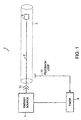
- a medical apparatus 2 includes an energy source 1, a signal conduit 3, a light device 5 and an interventional device 7 for introducing the light device 5 to an internal tissue region.
- the energy source for example, may be an external battery, power supply, pulse generator or RF generator.
- the energy source 1 may be controlled by a computer or microprocessor.
- the energy source 1 delivers energy to a port 11.
- the medical apparatus also includes a timer 9 for limiting the duration of the energy delivered to the port 11.
- a signal conduit 3 extends along the length of the interventional device 7 and provides electrical communication between the port 11 and the light device 5.
- the signal conduit 3, for example, comprises an ordinary twisted wire, coaxial cable, metallized traces or other suitable signal carrying conduit.
- the signal conduit 3, in bipolar mode, includes at least one signal wire and one return wire.
- the signal conduit 3 may operate in monopolar mode in certain instances.
- the interventional device 7 is a catheter
- the signal conduit 3 is a wire, having a diameter ranging anywhere from about 0.005 inches to about 0.080 inches. A wire having a diameter in this range does not greatly impact the flexibility or size of the catheter 7.
- metal bodied catheters, guide wires or needles provide the return path using the conductivity of the metal body.
- the medical apparatus 2 further includes a feedback loop conduit 13.
- the feedback loop conduit collects and returns a small portion of the light energy generated by the light device 5.
- the catheter body conducts some of the light generated at a distal tip of the catheter 7 back to a proximal end of the catheter 7, permitting an operator to observe or confirm the operation of the medical apparatus 2 simply by looking at the proximal end of the catheter 7.
- the returned energy is coupled to the energy source 1 to provide a controlling feedback in response to onset of illumination, intensity or spectral components.
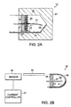
- the light device not belonging to the invention, is an arc lamp 14.
- An arc lamp is an electric lamp in which light is produced by an arc made when current flows through ionized gas between two electrodes.
- the arc lamp 14 includes a pair of electrodes 23, 27.
- the electrodes 23, 27 are spaced from one another for striking an arc.
- a housing 15 surrounds the arc lamp 14.
- the housing comprises quartz 15.
- the electrodes 23, 27 are sealed inside a cavity 20 defined by the housing 15.
- a sintered metal 17 with a glass or epoxy 19 seal the arc lamp 14.
- the sintered metal 17 is copper.
- the sintered metal 17 absorbs some of the vapors generated from the operation of the arc lamp 14 and reduces clouding during operation.
- the glass or epoxy seal 19 yields at high pressure, preventing the housing 15 from fracturing. Sealing the arc lamp 14 prevents any debris or escaping gas generated by the arc lamp 14 from leaving the confines of the interventional device 7.
- An insulator 21 isolates the first electrode 23 from the sealing material 17, 19.
- a distal end of the first electrode 23 has a hemispherical shape and comprises coating of a material such as carbon or tungsten.
- the second electrode 27 forms the return electrode.
- the second electrode 27 is formed along one side 16 of the housing 15.
- a separator 29 protects the second electrode 27 and prevents current from the second electrode 27 from flowing through the sintered metal 17.
- the inner surface of the housing 15 is coated with a conductive trace of aluminum 25. In one embodiment, a vacuum metallizing process coats the inner surface. The thickness of the aluminum is enough to sustain an arc for a short period of time, while transmitting a useful amount of light energy.
- the shape of the housing 15 permits collecting and redirecting some of the light energy generated by the arc lamp 14 to the proximal end of an interventional device in communication with the arc lamp 14.
- the flat front surface 31 of the housing 15 may include additional lenses. Alternatively, masking may modify the shape of the housing 15. In addition, the flat surface 31 may be coated with a reflective substance.
- the thick wall of the housing 15 may be coupled to one or more light guides, comprising optical fibers, transparent cylindrical catheter bodies and the like, to conduct some of the reflected light energy to the proximal end of the interventional device for the purpose of providing a feedback system.
- the housing 14 provides means for cooling the arc lamp 14.
- the housing may include passages for a cooling fluid to flow.
- a jacket of water, air or other fluid may surround the housing 14.
- a light system 32 not belonging to the invention, having an arc lamp 34, illustrates the usefulness of a feedback mechanism.
- a feedback mechanism To "strike an arc," one must either bring two electrodes close together and then separate them by a distance, or if that is not possible, raise the voltage applied to the electrodes gradually until an arc is struck and then, drop the voltage quickly.
- An ordinary current sensing circuitry may assist this process by sensing an increase in current flow as the arc is struck and sustained. While the current sensing circuitry may be useful, a better arrangement is to sample the actual light output, which is responsive to slight changes in applied power and erosion of the electrodes within. This capability is especially valuable, since the burning time of the arc may be in the order of a few milliseconds, short enough to prevent heating and destruction of the carrying member or the surrounding anatomy.
- the light system 32 includes an arc lamp 34 in communication with a feedback system 36.
- the arc lamp 34 comprises a first metal electrode 37 disposed at the center of a cavity defined by a hemispherical quartz dome 35.
- the electrode 37 is held stationary by copper wool 39, tightly packed to seal the arc lamp 34.
- the copper wool 39 absorbs the fumes emitted by the arc.
- the light system 32 includes a second electrode 43 or a return path for the arc.
- a flash metallization 43 process may form the return path 43.
- the return path 43 formed by flash metallization is sufficient for a short duration emission of an extremely bright output of wide spectral bandwidth including infrared (IR), visible and ultraviolet (UV) components.
- the dome surface has a layer 41 of mercury, which enhances certain spectral wavelengths.
- the feedback system 36 includes a light guide 33, which is in communication with the arc lamp 34 at a distal end and a sensor 45 at a proximal end. The sensor 45 supplies light output to the current controller 47.
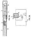
- the light device is a discharge lamp 57, which does not belong to the invention.
- a discharge lamp light is produced by an electric discharge between electrodes in a gas.
- a rod-like assembly 59 has a discharge tube 57 mounted on a distal end. The assembly 59 permits placement of the discharge tube 57 through various lumens including, for example, the lumen of a catheter with an optically clear structure or an endoscope.
- a transformer 61 disposed proximal to the discharge tube 57 provides a voltage step.
- the transformer 61 for example, consists of a copper wire wound around a cylindrical form and tapped at various points along the length of the wire.
- the transformer 61 may use a wire as small as 0.0127 cm (0.005 inches) in diameter, as long as it is capable of supplying adequate current at relatively high voltage.
- An example of a suitable wire is a common enamel-covered copper wire.
- the turns ratio between the transformer primary and the transformer secondary coil determines the step up ratio of the transformer 61.
- the transformer 61 requires only one tapped coil, thus saving space.
- the coil may be wound around a metallic core such as iron, which improves its efficiency.
- the core diameter ranges from about 0.0102 cm (0.004 inches) to about 0.2 cm (0.080 inches).
- the core length ranges from about 0.236 cm (0.093 inches) to about 2.54 cm (1.0 inch) or even longer.
- one or more layers of copper wire wraps around flexible cores of thin strips of iron to provide a flexible assembly that does not greatly interfere with the flexible characteristics of an interventional device.
- the discharge tube 57 includes a third wire or capacitively coupled electrode 71 placed adjacent the discharge tube 57.
- the third wire 71 extends along an interventional device and communicates with the reference ground of a power discharge source.
- the third wire 71 improves the flash output of the discharge tube 57 by providing an approximately equipotential charge along the length of the discharge tube 57, thereby improving reliability, while reducing the peak voltage needed for flash onset.
- the discharge tube 57 is mounted directly at the distal end of the transformer 61. In another embodiment, the discharge tube 57 is separated from the transformer 61 with wires 73. A variety of materials can fill the discharge tube 57.
- the discharge tube is a flash tube filled with gas 75 such as xenon, argon or krypton, providing various spectral output.
- gases 75 such as xenon, argon or krypton
- combinations of gases with other substances, such as xenon and a chloride fill the flash tube 57. The combination of xenon and chloride produces output with prominent spectral lines in the ultraviolet (UV) region at around 308 nm or shorter. It is difficult to deliver spectral output in the UV region through an ordinary optical fiber due to loss through attenuation.
- the flash tube 57 is frosted or coated with a phosphorescent or fluorescing material such as borax.
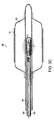
- An interventional device may include an elongated discharge tube 77 or a series of tubes capable of being passed though a channel of an interventional device.
- the length of the intervention device may be 2 meters or more.
- the discharge tube 77 diameter for example, may be approximately 0.317 cm (0.125 inches) and the discharge tube 77 length, for example, may be approximately 2.54 cm (1 inch).
- a transparent sheath housing 85 surrounds the discharge tube 77 to protect the discharge tube 77 and to prevent the discharge tube 77 from contacting the wall of a bodily channel being illuminated.
- suitable housing 85 materials include polyethylene and polypropylene. UV absorption, however, can be high in such materials.
- these materials must be sufficiently thin walled (eg., about 0.005 cm (0.002 inches)) to reduce the net loss of UV energy to a manageable level.
- the relative lack of rigidity of the sheath material can be compensated by stretching the material, which has been formed into a cylindrical sheath over the discharge tube 77 or by inflating a section of the discharge tube 77 so that it takes on a more rigid form.
- an equipotential discharge tube 77 reduces the possibility of hot spot formation.
- An equipotential discharge tube 77 has a shape, which provides a more even voltage gradient across a section of the tube 77, and therefore a more distributed discharge upon firing.
- a dielectric material 78 surrounds the tube 77.
- a pair of electrodes 75, 76 formed by metallization contacts opposite sides of the dielectric material 78.
- a suitable dielectric material 78 for example, includes glass or polystyrene.
- the voltage gradient across the electrodes 76 is made more uniform by reducing edge effects. Edge effects may be reduced by creating a local condition with greater amount of gas 75 in the tube and a smaller amount of the dielectric material 78.
- the discharge tube 77 is in communication with a current source 81 such as a battery and a capacitor discharge storage 79.
- the battery 81 charges the capacitor 79 to store energy, and the stored energy is discharged and applied to the discharge tube 77 by opening a normally closed switch 83.
- an RF current of either a continuous waveform (CW) or a pulsed form effectively creates a high voltage at the electrodes 75, 76 of the discharge tube 77 to generate light output.
- an endoscope provides means for introducing the light devices of Figures 3A and 3B. Once the light device is properly positioned, the light device discharges a desired spectrum of light to perform a medical procedure.
- One medical procedure performed in this manner is destroying or ablating a thin layer of cells on the surface of an organ or the inner wall of a vessel such as the esophagus using ultraviolet energy.
- the broad spectrum of emission of a xenon type flash tube which contains IR, visible and UV components, for example, may be used to ionize, heat and/or irradiate a surface. This action may also kill foreign cells such as bacteria or various viruses.
- provisional patent application serial no. 60/033,333 published as EP-A-939 894.
- Another commonly-owned U.S. provisional patent application is U.S. provisional patent application serial no. 60/033,334.
- Another medical procedure performed with such a device is tissue spectroscopy. Short duration UV pulses can excite intrinsic fluorophores that may be present in a tissue region. For this application, the output of the discharge lamp may be filtered so that its radiation is restricted to the blue or UV region of the spectrum. Still another medical procedure performed, includes activation of a photoactive drug.
- a balloon catheter 90 includes the light device of FIG. 3A. Air or fluid may inflate the balloon portion 92 of the catheter 90.
- the balloon 92 includes a polymeric stent 92.
- the discharge lamp 57 inside the balloon 93 hardens the distended polymeric stent 92 by irradiating the polymeric stent 91.
- the polymeric stent 91 comprises a UV-curable epoxy or adhesive to assist in hardening of the stent 91.
- Loctite 3761® adhesive "Litetak”® is an example of a UV-curable adhesive.
- a fibrous stent may be hardened by impregnating the stent with some of the UV-curable adhesive and illuminating it with the intense light output of the discharge tube in-vivo.
- the inflation lumen 95 may include a cooling fluid to cool the discharge tube 57.
- An inner sliding member 96 may be used to adjust the position of the discharge tube 57 inside the balloon 93.
- a sonoluminescent light device provides light output in the X-ray spectrum region.
- the term "sonoluminescence” refers to luminescence produced by high frequency sound waves.
- the operation of the sonoluminescent effect is currently somewhat of a mystery; however, it has been shown that sufficiently high acoustic powers may be generated with practical ultrasonic transducers and the sound waves focused to a point in a sound conducting medium may emit a short pulse of light energy including the ultraviolet region to X-ray region. Therefore, it becomes possible to generate X-rays at the distal tip of a flexible catheter.
- the sonoluminescent light device 101 includes a housing 103, an acoustic transducer 110, and an acoustic conducting medium 105.
- the housing 103 encloses the acoustic conducting medium 105.
- the acoustic conducting medium 105 is disposed in the pathway of sound waves generated by the acoustic transducer 110.
- the acoustic transducer 110 includes a piezoelectric material 113 and an integral matching layer 107. Lead zirconate-titanate is an example of a piezoelectric material 113, which can be used to form the acoustic transducer 110. Other suitable piezoelectric materials 113 may also be used to convert electrical energy to mechanical energy.
- the sonoluminescent light device 101 further comprises a focusing lens 109, which is curved to provide a sharp spot of focused sound waves in the acoustic conducting medium 105.
- the focusing lens 109 sits in between the acoustic transducer 110 and the acoustic conducting medium 105.
- the sonoluminescent light device 101 comprises two electrodes.
- the first electrode 111 attaches to the back of the piezoelectric material 113 .
- the second electrode attaches to the face of the acoustic transducer 110.
- the thickness of the piezoelectric layer 113 determines the frequency of the operation.
- the wave matching layer 107 is a 1/4 wave matching layer 107 made of a material such as silver filled epoxy.
- the wave matching layer 107 serves as both an electrode and a matching layer. In another embodiment, the wave matching layer 107 is shaped into a focusing lens to concentrate the ultrasound beam. In one embodiment, the acoustic conducting medium 115 comprises water. In another embodiment, the acoustic conducting medium 115 comprises a solid substance or target, on which the sonoluminescent effect can be observed.
- a pulse generator 112 provides a high voltage pulse or pulses to the transducer 110 via cable lines 114. A train of pulses may be employed to produce a series of light or X-ray output events, and the pulses may be stepped up or down in voltage using a transformer.
- the distal end 117 of the housing 103 is shaped to permit further reflection and concentration of the acoustic waves.
- the acoustic signals when insonified, may radiate photonic energy including X-rays.
- the sonoluminescent light 101 can be implanted inside a body.
- the sonoluminescent light device 101 can also be inserted inside an interventional device and the focal point of the acoustic signals lies outside the light assembly and inside the interventional device.
- the interventional device may simply be a cap, cover, or needle.
- the sonoluminescent light may be placed within a catheter, guide wire, endoscope or introducer.
- the sonoluminescent phenomenon is currently under investigation and may affect matter and living tissue in previously unobserved ways and the use of a medical device in conjunction with a transducer capable of generating the sonoluminescence may find uses that have not been anticipated.
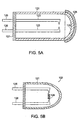
- a multi-electrode spark gap module 121 which does not form part of the invention, includes a pair of electrodes 123 held inside a housing 121.
- the multi-electrode spark gap module 21 is capable of generating a spark across the gap of the electrodes 123, in response to the application of electronic pulses.
- a spark is a short duration electric discharge caused by sudden breakdown of air or some other dielectric material separating two terminals. The electric discharge produces a flash of light.
- the spark gap module 121 operates in a way similar to the arc lamp of FIG. 2A, except that the cap does not necessarily have to be conductive in order to generate an emission when the current flow is established at the onset of discharge.
- the spark gap module 121 provides certain advantages, such as lower heat generation during operation and ease of manufacturing.
- the spark gap module 121 includes electrodes 123 sealed in a glass envelope 125, in an manner similar to conventional spark gaps used to control static discharge. Leads 126 supply electrical power to the electrodes 123.
- An insulator 127 seals the module 121 and separates the leads 126 from each other. Examples of materials appropriate to form the insulator 127 include plastic, glass and other nonconductive materials.
- a filter layer 128 disposed at the distal end of the spark gap module 121 enhances the output of the blue and UV region of the spectrum.
- the filter layer 128 may comprise an inexpensive dyed plastic dip coat or a more expensive dichroic coating.
- an incandescent light source 122 which does not form part of the invention, provides high intensity short duration light output.
- the incandescent light source 122 has the same basic structure as the spark gap module of FIG. 5A, except that the incandescent light source 122 includes a filament 129 (i.e., non-gap).
- the incandescent lamp 122 includes two electrodes encased in a housing 121 and a tungsten filament 129 bridging the two electrodes. The incandescent light source 122 generates high intensity, short duration light without generating excessive heat.
- the incandescent light source 122 can generate emissions of less than 100 milliseconds with color temperature of about 5000 degrees Kelvin, which includes substantially blue and UV light energy.
- Other filaments, vacuum or gas-filled enclosures, including oxygen filled and oxidizing filaments like those used in flash bulbs may be used to generate light of various colors.
- Certain medical procedures such as photodynamic therapy (PDT) or tissue spectroscopy including fluorescence and Raman spectroscopy require monochromatic light output at high intensities.
- PDT photodynamic therapy
- tissue spectroscopy including fluorescence and Raman spectroscopy require monochromatic light output at high intensities.
- One method of generating a monochromatic output is to use a filter. This method, however, may be inefficient when highly attenuative filtering techniques are employed.
- Another method of generating a monochromatic light is to use a laser.
- Typical laser diodes which are commonly found in laser pen pointers have outputs in the red region with power levels typically in the 1-7 mW range. Lasers can be made very small in size using semiconductor fabrication processes. A typical laser diode assembly is about 0.952 cm (0.375 inches) in diameter, but most of that size is attributed to the case and tabs for solder connections.
- the actual light generating portion of the diode is in the order of a few microns in thickness and a few tens of microns in width and length. Therefore it is reasonable to predict that laser diode fabrication in the range of 0.0254 cm (0.010 inches) to 0.203 cm (0.080 inches) will be practical and economical for use in catheter based devices.
- One drawback of the laser diode is that it is available in only a few wavelengths mostly within the IR and red regions, and none currently in the UV regions.
- UV laser diodes will exist in the future, but in the meantime a practical way to double the frequency of operation is by introducing a volume of an optically nonlinear material followed by a filter that doubles the frequency of the laser diode.
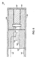
- the light device 132 which does not form part of the invention, includes a laser diode 131 and a frequency multiplier 137.
- the laser diode 131 is capable of producing coherent laser light, which emanates from a narrow gap 133 in the diode structure 131.
- the frequency multiplier is a KDP crystal 137 placed distal to the laser diode 131, and the laser diode 131 and the frequency multiplier 137 are held in proximity to the tip of a carrying body 139.
- a high pass filter 141 is mounted on the opposite side of the laser diode 131 so that any light of the fundamental frequency is absorbed or reflected and only the multiplied waveform remains.
- a diode mount 143 and a lens holder 145 maintain the relationship of the elements within the carrying body 139.
- a pair of wires 147 supply DC power to the diode 131 from a connector at the proximal end of the carrying body 139.
- a heat sink 146 supporting the laser diode 131 prevents overheating of the laser diode 131.
- the laser diode 131 is cooled further by fluid flow in the interventional device. It should be pointed out that the efficiency of frequency doubling in this manner is extremely poor and that outputs greater than -40dB relative to the source is expected. In the past, this feature has made most applications of frequency multiplying crystals to laser diode devices impractical.
- the efficiency is tolerable since the light loss functions of intervening materials may be negligible and the power requirements are low.
- the light device 132 includes an ordinary light emitting diodes, which generates a non-coherent output.
- a fluorescent lighting device can generate monochromatic or relatively narrow band light wave energy.
- the fluorescent lighting device may be gas filled tubes, which fluoresce at known wavelengths and produce output spectra composed of discrete lines.
- an RF driven fluorescent lighting device 150 which does not belong to the invention, generates monochromatric light.
- the fluorescent light device 150 may be inserted inside an interventional device such as a catheter or a guide wire.
- the fluorescent light device 150 includes a tube 159 filled with argon gas 157.
- the tube 159 is pressurized or partially evacuated and then sealed.
- a pair of signal wires 151 electrically connect a transformer 153 to the tube 159 through a pair of electrodes 155 located on opposite sides of the tube 159.
- the transformer 153 may step up an ordinary 60 Hz AC voltage to a higher voltage. Higher frequencies ranging from about 60Hz to about 200GHz provide greater efficiencies and more stable light output.
- an RF generator connects to a proximal end of an interventional device carrying the lighting device 150. This example provides even greater efficiencies, since there is no need to supply RF energy to the interventional device via external means.
- a fluorescent light device 160 not belonging to the invention, includes a Gunn-effect diode 161 placed adjacent a resonant dielectric resonator 163.
- the light device 160 includes an additional cavity resonator 165 to provide a higher RF voltage to a gas tube 167.
- the cavity resonator 165 is filled with glass microspheres to improve strength of the assembly, which would otherwise be hollow.
- the gas 169 placed inside the gas tube 167 may be any gaseous substance that will not explode when excited with RF energy, will fluoresce when DC current is applied through wires 171 in electrical communication with the diode 161 and resonator 165, causing the diode 161 to emit RF energy.
- Examples of other types of light generating systems not specifically described herein are electroluminescent panels, mechanical sparking, various incandescent and combustion generated light, chemical luminescence and others. Numerous light sources can be placed at a distal end of an interventional device by a combination of miniaturization and use of short duration energy.
- an interventional device having at least a portion that is optically transmissive may include any of the aforementioned energy sources.
- the interventional device is sized to permit passage through at least one of its lumens.
- a portion of the interventional device may function as the housing for the various light devices. It should be understood that any of the features herein referred to as catheter or catheter sheath also refers to other interventional devices such as a guide wire, guiding catheter, endoscope and needle art.
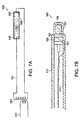
- a catheter 200 may be used to introduce a light device inside a body.
- the catheter 200 includes a catheter body 201, a fluid port 203, an optically transparent window 209 and an aperture 211 located at a distal end 207 of the catheter 200.
- the catheter body 201 for example, comprises an extruded plastic such as polyethylene, nylon, PET, or polyimide.
- the fluid port 203 located near a proximal end 206 of the catheter 200 allows introduction of various substances such as drugs, fluorescing agents, ultrasound transducers, pressure transducers, flush, cooling or irrigation fluids or optical coupling fluids.
- the fluid port 203 comprises a side arm and a Luer fitting, as commonly used in the catheter art.
- the proximal end 206 of the catheter 200 further comprises a connector 205 capable of electrical and/or optical connection.
- the catheter 200 includes both optical and electrical connection made simultaneously.
- the distal end 207 of the catheter 200 is fitted with an optically transparent window 209 and an aperture 211, through which fluid or light wave energy may pass.
- the material for the transparent window 209 is chosen to efficiently transmit various emission wavelengths generated by the light system incorporated inside the catheter 200. For example, where the light device generates UV light, compromise between strength of the window 209 and the thickness of the window 209 may be necessary, since UV spectrum tends to attenuate when passing through a plastic material. In the embodiment of FIG.
- an aperture located adjacent the light source allows the generated light to reach an interior tissue region.
- a low loss glass such as quartz is bonded to the distal tip 207 of the catheter 200.
- the X-ray radiation may be emitted through a denser material such as a metal, which may serve to house and shield, redirect or focus the X-rays at the distal tip 207 of the catheter 200.
- the energy producing transducer protrudes through an open end of the catheter 200.
- a light device placed inside the catheter 200 contacts the inner surface of the distal end 207 of the catheter 200 to affix the light device location.
- the light device is located in registration with a window 209 or another location throughout the length of the catheter 200.
- the placement of the light device is adjustable using a proximal holder, which allows the user to pre-position the light device inside the catheter 200 or to move the light device and the catheter 200 relative to each other during use.
- moving the light device relative to the catheter 200 during use allows the light device to illuminate various regions of the anatomy without having to move the catheter.
- the light device inside the catheter 200 creates an image either by rotating the catheter 200 or the light device inside the catheter 200, or by sliding the light device relative to the catheter body 201 to effect a scanning action.
- a hollow needle 210 is configured to introduce a light device of the present invention near an interior tissue region.
- the needle 200 includes a shaft 219, a beveled tip 221 at a distal end of the needle 210 and an aperture 217 sized to accept the light device at a proximal end of the needle 210.
- the needle shaft 219 comprises stainless steel with a wall thickness of about 0.00762 cm (0.003 inches) and a length of about 210 millimeters.
- the beveled tip 221 may be sharpened to permit easy insertion of the needle 210 and a pathway for the light device.
- An operator uses an external x-ray or ultrasound imaging technique to first locate an internal tissue region of interest. The operator then inserts the needle 210 inside the body under image guidance until the tip 221 reaches the region of interest.
- the needle 210 allows the light device to be inserted into the body through the aperture 217 of the needle 210 and be located near the tissue region. The operator may confirm the position of the light device using the aforementioned image guidance. Once satisfied that the light device is in the proper place, the operator applies power to the light device to generate light.
- a guide wire 225 placed inside a preexisting channel may deliver a light device of the present invention near an internal tissue region.
- the guide wire 225 has a single central lumen 226 extending through the guide wire body 227 and a guide wire coiled tip 229.
- the guide wire body 227 for example, comprises hypo tube, plastic extrusion, or wound wires.
- the tip 229 for example, comprises coiled stainless steel or platinum wires.
- the outside diameter of the guide wire 225 ranges from about 0.089 cm (0.035 inches) to about 0.0254 cm (0.010 inches.)
- the inside diameter of the lumen 226 ranges from about 0.0812 cm (0.032 inches) to about 0.0102 cm (0.004 inches).
- the guide wire 225 length ranges from about 100 cm to about 200 cm.
- the guide wire 225 with a length in this range is useful for reaching the GI tract, brain, heart and other remote internal tissues.
- a shorter guide wire 225 introduces a light device to less remote areas such as the tear ducts or breast milk ducts.
- an endoscope 235 may deliver a light device of the present invention near an internal tissue region through an access port 237.
- the endoscope 235 further includes an eye piece 239 and a flush lumen 241 used to flush a guide the location of the tip of the endoscope.
- the access port 237 may be relatively large to allow a light device to easily pass through. In one embodiment, the access port 237 has a diameter up to about 0.475 cm (0.187 inches).
- the endoscope 235 is useful for delivering high energy emission such as that afforded by the xenon flash tube module to an area of the body such as the esophagus.
- an introducer 251 may deliver a light device of the present invention near an internal tissue region.
- the introducer 251 includes a Touhey-Borst fitting 253, a side arm 255, a single lumen plastic sheath 257, and an open distal end.
- the open distal end 259 of the introducer 251 is inserted into arteries or veins and another interventional device comprising a light device is introduced into the internal tissue region through the introducer 251.
- the guide wire shown in FIG. 8C, the catheter shown in Figure 8A and the needle shown in FIG. 8B are examples of interventional devices, which may comprise a light device of the present invention and which may pass through the introducer 251 to be placed near an internal tissue region of interest.
Abstract
Description
- This invention relates to light sources and, more particularly, to miniature light sources for placement inside a body for tissue characterization and treatment.
- Physicians have used light for performing diagnosis and therapy of tissue by delivering light to the tissue. Medical applications that use light include, for example, photoactivation of drugs, monitoring of blood glucose levels, tissue spectroscopy, illumination of internal tissue, and tissue ablation. Light system designers have come up with a variety of methods to deliver light to a tissue region of interest. Medium powered light emitting diode arrays placed on catheters and probes are available for activating photoactive drugs such as HPD (Photofrin) and SNeT2 (Tin Etlopurpurin Dichloride) to perform photodynamic therapy (PDT). Most of the light system that generate high energy light are external light sources that use optical fibers to deliver the light to a variety of anatomical locations inside the body. Other ways to deliver energy to an internal tissue region include direct heating via conduction loss through a catheter or balloon electrodes, radioactive seeding passed through needles or catheters, inserting cryogenically cooled catheter tips, and using various light diffusers or ultrasonic transducers.
- In general, health services under managed care guidelines require that medical procedures be more effective, faster, and inexpensive. Several promising medical diagnosis and treatment systems using light wave energy have failed to become commercially successful due to the high cost of the instruments. Most high energy light systems are expensive, large, and complex because they require an external light source, light conducting fibers, transducers, and connectors.
- The use of optical fibers to deliver light presents several problems. In order to transport an adequate amount of light energy from the light source to an internal tissue region, a significant amount of optical fibers must be included in an interventional device. An interventional device (e.g., catheter, endoscope, guide wire, needle or introducer), however, does not include a lot of space and higher quality optical fibers, which take up less space, are expensive. Optical fibers also lack mechanical properties necessary to be used with an interventional device. Optical fibers can break when flexed and have a relatively high stiffness as compared to conventional catheter materials. Therefore, it is difficult to design a flexible tip for a catheter that includes optical fibers. Overall flexibility of an interventional device that includes optical fibers is limited. Furthermore, optical fibers require an expensive terminating connector and must be properly coupled to afford adequate light throughput. Signal efficiency of fiber based devices depends greatly upon the ability of the device to couple sufficient light into the fibers at the desired wavelength, but it is a challenge to efficiently couple light from a lamp source into fibers with small diameters.
- Known high energy light systems also tend to cause undesirable side effects. The high intensity light, which is necessary for medical procedures, can cause thermal destruction of normal tissue regions, since the light signals have high intensity as well as long duration.
- WO-A-92/15253 is prior art to the present application. WO-A-91/15253 discloses an interventional device comprising a housing, an acoustic transducer and an acoustic conducting medium inside the housing and adjacent the acoustic transducer. The device has a lens for focussing ultrasound in the tissue outside the housing. The present invention is as claimed in the independent claims optional features are recited in the dependent claims.
- The present invention relates to improved high energy light systems for use in interventional devices for medical applications. The high energy light systems according to the invention include miniature light sources capable of generating high intensity modular light waves and capable of being placed at or near the tips of various interventional devices (e.g., a catheter, endoscope, guide wire, needle or introducer). The present invention, therefore, eliminates the need for expensive proximally located light sources, transducers, fibers, and connectors. The present invention further provides light sources that generate modular light output in a spectrum ranging from the ultraviolet to x-rays. The high output, short duration light waves allow safe operation without excessive heating effects.
- In general, in one aspect, the invention features an interventional device including a miniature light device for generating and delivering high energy modular photonic energy to an internal tissue region for diagnostic and/or therapeutic purposes. The light device is capable of being placed at or near a distal end of the interventional device, eliminating the need for light carrying conduits to deliver light generated by an external light source. The device may further include a feedback system and a light guide for supplying light output to the feedback system.
- The light device is a sonoluminescent light module. The sonoluminescent light module includes a housing, an acoustic transducer and an acoustic conducting medium. The acoustic conducting medium is positioned inside the housing adjacent the acoustic transducer. The acoustic transducer comprises a piezoelectric material and a wave matching layer. The sonoluminescent light module is capable of generating light spectrum in the X-ray region.
- The foregoing and other objects, aspects, features, and advantages of the invention will become more apparent from the following description and from the claims.
- In the drawings, like reference characters generally refer to the same parts throughout the different views. Also, the drawings are not necessarily to scale, emphasis instead generally being placed upon illustrating the principles of the invention.
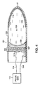
- FIG. 1 is a schematic representation of a medical apparatus comprising an energy source, a signal conduit, and an energy emitter inserted in an interventional device.
- FIG. 2A is a diagram of an arc lamp for placement inside a body.
- FIG. 2B is a diagram of an arc lamp in communication with a feedback system.
- FIG. 3A is a diagram of a discharge tube placed at a distal end of an interventional device.
- FIG. 3B is a diagram of a discharge tube in communication with a battery and a capacitor.
- FIG. 3C is a diagram of the discharge tube of FIG. 3A placed inside a balloon catheter deploying a stent.
- FIG. 4 is a diagram of an embodiment of the invention of a sonoluminescent light source in communication with a pulse generator.
- FIG. 5A is a diagram of a multi-electrode spark gap for placement inside an interventional device.
- FIG. 5B is a diagram of an incandescent light source.
- FIG. 6 is a diagram of a laser diode driven light source placed at a distal end of an interventional device.
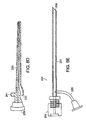
- FIG. 7A is a diagram of a discharge lamp in communication with a transformer.
- FIG. 7B is a diagram of a fluorescent lighting device driven by a Gunn diode.
- FIG. 8A is a diagram of a catheter for use with a miniature light device.
- FIG. 8B is a diagram of a needle for use with a miniature light device.
- FIG. 8C is a diagram of a guide wire for use with a miniature light device.
- FIGS. 8D and 8E are diagrams of endoscopes for use with a miniature light device.
-
- Referring to FIG. 1, a
medical apparatus 2 includes anenergy source 1, asignal conduit 3, alight device 5 and aninterventional device 7 for introducing thelight device 5 to an internal tissue region. The energy source, for example, may be an external battery, power supply, pulse generator or RF generator. Theenergy source 1 may be controlled by a computer or microprocessor. Theenergy source 1 delivers energy to a port 11. The medical apparatus also includes atimer 9 for limiting the duration of the energy delivered to the port 11. Asignal conduit 3 extends along the length of theinterventional device 7 and provides electrical communication between the port 11 and thelight device 5. Thesignal conduit 3, for example, comprises an ordinary twisted wire, coaxial cable, metallized traces or other suitable signal carrying conduit. Thesignal conduit 3, in bipolar mode, includes at least one signal wire and one return wire. Alternatively, thesignal conduit 3 may operate in monopolar mode in certain instances. In one embodiment, where theinterventional device 7 is a catheter, thesignal conduit 3 is a wire, having a diameter ranging anywhere from about 0.005 inches to about 0.080 inches. A wire having a diameter in this range does not greatly impact the flexibility or size of thecatheter 7. In another embodiment, metal bodied catheters, guide wires or needles provide the return path using the conductivity of the metal body. - Still referring to FIG. 1, the
medical apparatus 2 further includes afeedback loop conduit 13. The feedback loop conduit collects and returns a small portion of the light energy generated by thelight device 5. In one embodiment, where theinterventional device 7 is an optically transparent catheter, the catheter body conducts some of the light generated at a distal tip of thecatheter 7 back to a proximal end of thecatheter 7, permitting an operator to observe or confirm the operation of themedical apparatus 2 simply by looking at the proximal end of thecatheter 7. In another embodiment, the returned energy is coupled to theenergy source 1 to provide a controlling feedback in response to onset of illumination, intensity or spectral components. - Referring to FIG. 2A, the light device, not belonging to the invention, is an
arc lamp 14. An arc lamp is an electric lamp in which light is produced by an arc made when current flows through ionized gas between two electrodes. Thearc lamp 14 includes a pair ofelectrodes electrodes housing 15 surrounds thearc lamp 14. In one embodiment, the housing comprisesquartz 15. Theelectrodes cavity 20 defined by thehousing 15. Asintered metal 17 with a glass or epoxy 19 seal thearc lamp 14. In one embodiment, thesintered metal 17 is copper. Thesintered metal 17 absorbs some of the vapors generated from the operation of thearc lamp 14 and reduces clouding during operation. The glass orepoxy seal 19 yields at high pressure, preventing thehousing 15 from fracturing. Sealing thearc lamp 14 prevents any debris or escaping gas generated by thearc lamp 14 from leaving the confines of theinterventional device 7. An insulator 21 isolates thefirst electrode 23 from the sealingmaterial first electrode 23 has a hemispherical shape and comprises coating of a material such as carbon or tungsten. Thesecond electrode 27 forms the return electrode. Thesecond electrode 27 is formed along oneside 16 of thehousing 15. A separator 29 protects thesecond electrode 27 and prevents current from thesecond electrode 27 from flowing through the sinteredmetal 17. The inner surface of thehousing 15 is coated with a conductive trace ofaluminum 25. In one embodiment, a vacuum metallizing process coats the inner surface. The thickness of the aluminum is enough to sustain an arc for a short period of time, while transmitting a useful amount of light energy. - Still referring to FIG. 2A, the shape of the
housing 15 permits collecting and redirecting some of the light energy generated by thearc lamp 14 to the proximal end of an interventional device in communication with thearc lamp 14. The flatfront surface 31 of thehousing 15 may include additional lenses. Alternatively, masking may modify the shape of thehousing 15. In addition, theflat surface 31 may be coated with a reflective substance. In this embodiment, the thick wall of thehousing 15 may be coupled to one or more light guides, comprising optical fibers, transparent cylindrical catheter bodies and the like, to conduct some of the reflected light energy to the proximal end of the interventional device for the purpose of providing a feedback system. - In another example, the
housing 14 provides means for cooling thearc lamp 14. The housing may include passages for a cooling fluid to flow. Alternatively, a jacket of water, air or other fluid may surround thehousing 14. - Referring to Figure 2B, a
light system 32, not belonging to the invention, having anarc lamp 34, illustrates the usefulness of a feedback mechanism. To "strike an arc," one must either bring two electrodes close together and then separate them by a distance, or if that is not possible, raise the voltage applied to the electrodes gradually until an arc is struck and then, drop the voltage quickly. An ordinary current sensing circuitry may assist this process by sensing an increase in current flow as the arc is struck and sustained. While the current sensing circuitry may be useful, a better arrangement is to sample the actual light output, which is responsive to slight changes in applied power and erosion of the electrodes within. This capability is especially valuable, since the burning time of the arc may be in the order of a few milliseconds, short enough to prevent heating and destruction of the carrying member or the surrounding anatomy. - Still referring to Figure 2B, the
light system 32, not belonging to the invention, includes anarc lamp 34 in communication with a feedback system 36. Thearc lamp 34 comprises afirst metal electrode 37 disposed at the center of a cavity defined by ahemispherical quartz dome 35. Theelectrode 37 is held stationary bycopper wool 39, tightly packed to seal thearc lamp 34. Thecopper wool 39 absorbs the fumes emitted by the arc. Thelight system 32 includes asecond electrode 43 or a return path for the arc. Aflash metallization 43 process may form thereturn path 43. Thereturn path 43 formed by flash metallization is sufficient for a short duration emission of an extremely bright output of wide spectral bandwidth including infrared (IR), visible and ultraviolet (UV) components. In one embodiment, the dome surface has alayer 41 of mercury, which enhances certain spectral wavelengths. The feedback system 36 includes alight guide 33, which is in communication with thearc lamp 34 at a distal end and asensor 45 at a proximal end. Thesensor 45 supplies light output to thecurrent controller 47. - Referring to Figure 3A, the light device is a
discharge lamp 57, which does not belong to the invention. In a discharge lamp, light is produced by an electric discharge between electrodes in a gas. A rod-like assembly 59 has adischarge tube 57 mounted on a distal end. Theassembly 59 permits placement of thedischarge tube 57 through various lumens including, for example, the lumen of a catheter with an optically clear structure or an endoscope. Atransformer 61 disposed proximal to thedischarge tube 57 provides a voltage step. Thetransformer 61, for example, consists of a copper wire wound around a cylindrical form and tapped at various points along the length of the wire. A light system that generates short duration light waves permits the use of wire gages that would otherwise be too small to withstand heating effects in continuous service. Thetransformer 61 may use a wire as small as 0.0127 cm (0.005 inches) in diameter, as long as it is capable of supplying adequate current at relatively high voltage. An example of a suitable wire is a common enamel-covered copper wire. The turns ratio between the transformer primary and the transformer secondary coil determines the step up ratio of thetransformer 61. Thetransformer 61 requires only one tapped coil, thus saving space. The coil may be wound around a metallic core such as iron, which improves its efficiency. The core diameter ranges from about 0.0102 cm (0.004 inches) to about 0.2 cm (0.080 inches). The core length ranges from about 0.236 cm (0.093 inches) to about 2.54 cm (1.0 inch) or even longer. In one embodiment, one or more layers of copper wire wraps around flexible cores of thin strips of iron to provide a flexible assembly that does not greatly interfere with the flexible characteristics of an interventional device. - Still referring to FIG. 3B, the
discharge tube 57 includes a third wire or capacitively coupledelectrode 71 placed adjacent thedischarge tube 57. Thethird wire 71 extends along an interventional device and communicates with the reference ground of a power discharge source. Thethird wire 71 improves the flash output of thedischarge tube 57 by providing an approximately equipotential charge along the length of thedischarge tube 57, thereby improving reliability, while reducing the peak voltage needed for flash onset. - In one example, the
discharge tube 57 is mounted directly at the distal end of thetransformer 61. In another embodiment, thedischarge tube 57 is separated from thetransformer 61 withwires 73. A variety of materials can fill thedischarge tube 57. In one embodiment, the discharge tube is a flash tube filled withgas 75 such as xenon, argon or krypton, providing various spectral output. In another example, combinations of gases with other substances, such as xenon and a chloride fill theflash tube 57. The combination of xenon and chloride produces output with prominent spectral lines in the ultraviolet (UV) region at around 308 nm or shorter. It is difficult to deliver spectral output in the UV region through an ordinary optical fiber due to loss through attenuation. In one example, theflash tube 57 is frosted or coated with a phosphorescent or fluorescing material such as borax. - An interventional device, not forming part of the invention, may include an
elongated discharge tube 77 or a series of tubes capable of being passed though a channel of an interventional device. The length of the intervention device, for example, may be 2 meters or more. Thedischarge tube 77 diameter, for example, may be approximately 0.317 cm (0.125 inches) and thedischarge tube 77 length, for example, may be approximately 2.54 cm (1 inch). In the example of FIG. 3A, atransparent sheath housing 85 surrounds thedischarge tube 77 to protect thedischarge tube 77 and to prevent thedischarge tube 77 from contacting the wall of a bodily channel being illuminated. Examples ofsuitable housing 85 materials include polyethylene and polypropylene. UV absorption, however, can be high in such materials. Therefore, where generation of UV light is desired, these materials must be sufficiently thin walled (eg., about 0.005 cm (0.002 inches)) to reduce the net loss of UV energy to a manageable level. The relative lack of rigidity of the sheath material can be compensated by stretching the material, which has been formed into a cylindrical sheath over thedischarge tube 77 or by inflating a section of thedischarge tube 77 so that it takes on a more rigid form. - Referring to FIG. 3B, an
equipotential discharge tube 77 reduces the possibility of hot spot formation. Anequipotential discharge tube 77 has a shape, which provides a more even voltage gradient across a section of thetube 77, and therefore a more distributed discharge upon firing. Adielectric material 78 surrounds thetube 77. A pair ofelectrodes dielectric material 78. Asuitable dielectric material 78, for example, includes glass or polystyrene. In one example, the voltage gradient across theelectrodes 76 is made more uniform by reducing edge effects. Edge effects may be reduced by creating a local condition with greater amount ofgas 75 in the tube and a smaller amount of thedielectric material 78. In one example, thedischarge tube 77 is in communication with acurrent source 81 such as a battery and acapacitor discharge storage 79. Thebattery 81 charges thecapacitor 79 to store energy, and the stored energy is discharged and applied to thedischarge tube 77 by opening a normally closedswitch 83. In another example, an RF current of either a continuous waveform (CW) or a pulsed form effectively creates a high voltage at theelectrodes discharge tube 77 to generate light output. - In one example, an endoscope provides means for introducing the light devices of Figures 3A and 3B. Once the light device is properly positioned, the light device discharges a desired spectrum of light to perform a medical procedure. One medical procedure performed in this manner is destroying or ablating a thin layer of cells on the surface of an organ or the inner wall of a vessel such as the esophagus using ultraviolet energy. The broad spectrum of emission of a xenon type flash tube, which contains IR, visible and UV components, for example, may be used to ionize, heat and/or irradiate a surface. This action may also kill foreign cells such as bacteria or various viruses. This procedure is described in a commonly-owned U.S. provisional patent application, namely U.S. provisional patent application serial no. 60/033,333 published as EP-A-939 894. Another commonly-owned U.S. provisional patent application is U.S. provisional patent application serial no. 60/033,334. Another medical procedure performed with such a device is tissue spectroscopy. Short duration UV pulses can excite intrinsic fluorophores that may be present in a tissue region. For this application, the output of the discharge lamp may be filtered so that its radiation is restricted to the blue or UV region of the spectrum. Still another medical procedure performed, includes activation of a photoactive drug.
- Referring to FIG. 3C, a
balloon catheter 90 includes the light device of FIG. 3A. Air or fluid may inflate the balloon portion 92 of thecatheter 90. The balloon 92 includes a polymeric stent 92. Thedischarge lamp 57 inside theballoon 93 hardens the distended polymeric stent 92 by irradiating thepolymeric stent 91. In one example, thepolymeric stent 91 comprises a UV-curable epoxy or adhesive to assist in hardening of thestent 91. Loctite 3761® adhesive "Litetak"® is an example of a UV-curable adhesive. A fibrous stent may be hardened by impregnating the stent with some of the UV-curable adhesive and illuminating it with the intense light output of the discharge tube in-vivo. Theinflation lumen 95 may include a cooling fluid to cool thedischarge tube 57. An inner slidingmember 96 may be used to adjust the position of thedischarge tube 57 inside theballoon 93. - All of the light devices described thus far generate photonic energy in the infrared (IR), visible and ultraviolet range of the spectrum. Referring to FIG. 4, a sonoluminescent light device according to the
invention 101 provides light output in the X-ray spectrum region. The term "sonoluminescence" refers to luminescence produced by high frequency sound waves. The operation of the sonoluminescent effect is currently somewhat of a mystery; however, it has been shown that sufficiently high acoustic powers may be generated with practical ultrasonic transducers and the sound waves focused to a point in a sound conducting medium may emit a short pulse of light energy including the ultraviolet region to X-ray region. Therefore, it becomes possible to generate X-rays at the distal tip of a flexible catheter. - Still referring to FIG. 4, the sonoluminescent
light device 101 includes ahousing 103, anacoustic transducer 110, and anacoustic conducting medium 105. Thehousing 103 encloses theacoustic conducting medium 105. Theacoustic conducting medium 105 is disposed in the pathway of sound waves generated by theacoustic transducer 110. Theacoustic transducer 110 includes apiezoelectric material 113 and anintegral matching layer 107. Lead zirconate-titanate is an example of apiezoelectric material 113, which can be used to form theacoustic transducer 110. Other suitablepiezoelectric materials 113 may also be used to convert electrical energy to mechanical energy. - The sonoluminescent
light device 101 further comprises a focusinglens 109, which is curved to provide a sharp spot of focused sound waves in theacoustic conducting medium 105. The focusinglens 109 sits in between theacoustic transducer 110 and theacoustic conducting medium 105. The sonoluminescentlight device 101 comprises two electrodes. Thefirst electrode 111 attaches to the back of thepiezoelectric material 113 . The second electrode attaches to the face of theacoustic transducer 110. The thickness of thepiezoelectric layer 113 determines the frequency of the operation. In one embodiment, thewave matching layer 107 is a 1/4wave matching layer 107 made of a material such as silver filled epoxy. Thewave matching layer 107 serves as both an electrode and a matching layer. In another embodiment, thewave matching layer 107 is shaped into a focusing lens to concentrate the ultrasound beam. In one embodiment, theacoustic conducting medium 115 comprises water. In another embodiment, theacoustic conducting medium 115 comprises a solid substance or target, on which the sonoluminescent effect can be observed. Apulse generator 112 provides a high voltage pulse or pulses to thetransducer 110 via cable lines 114. A train of pulses may be employed to produce a series of light or X-ray output events, and the pulses may be stepped up or down in voltage using a transformer. - Still referring to FIG. 4, in one embodiment, the
distal end 117 of thehousing 103 is shaped to permit further reflection and concentration of the acoustic waves. The acoustic signals, when insonified, may radiate photonic energy including X-rays. - The sonoluminescent light 101 can be implanted inside a body. The sonoluminescent
light device 101 can also be inserted inside an interventional device and the focal point of the acoustic signals lies outside the light assembly and inside the interventional device. The interventional device may simply be a cap, cover, or needle. Alternatively, the sonoluminescent light may be placed within a catheter, guide wire, endoscope or introducer. - The sonoluminescent phenomenon is currently under investigation and may affect matter and living tissue in previously unobserved ways and the use of a medical device in conjunction with a transducer capable of generating the sonoluminescence may find uses that have not been anticipated.
- Referring to FIG. 5A, a multi-electrode
spark gap module 121, which does not form part of the invention, includes a pair ofelectrodes 123 held inside ahousing 121. The multi-electrode spark gap module 21 is capable of generating a spark across the gap of theelectrodes 123, in response to the application of electronic pulses. A spark is a short duration electric discharge caused by sudden breakdown of air or some other dielectric material separating two terminals. The electric discharge produces a flash of light. Thespark gap module 121 operates in a way similar to the arc lamp of FIG. 2A, except that the cap does not necessarily have to be conductive in order to generate an emission when the current flow is established at the onset of discharge. Thespark gap module 121 provides certain advantages, such as lower heat generation during operation and ease of manufacturing. - Still referring to FIG. 5A, the
spark gap module 121 includeselectrodes 123 sealed in aglass envelope 125, in an manner similar to conventional spark gaps used to control static discharge.Leads 126 supply electrical power to theelectrodes 123. Aninsulator 127 seals themodule 121 and separates theleads 126 from each other. Examples of materials appropriate to form theinsulator 127 include plastic, glass and other nonconductive materials. - It is possible to use the light energy of this relatively small electrical discharge produced by a
spark gap module 121 to excite a volume of nearby tissue and determine its colors and fluorescence. The spectrum of the light generated by aspark gap module 121 contains blue and UV portions of the spectrum. This range is particularly useful for exciting fluorophors which may be present in the tissue. Afilter layer 128 disposed at the distal end of thespark gap module 121 enhances the output of the blue and UV region of the spectrum. Thefilter layer 128 may comprise an inexpensive dyed plastic dip coat or a more expensive dichroic coating. - Referring to FIG. 5B, an incandescent
light source 122, which does not form part of the invention, provides high intensity short duration light output. The incandescentlight source 122 has the same basic structure as the spark gap module of FIG. 5A, except that the incandescentlight source 122 includes a filament 129 (i.e., non-gap). In one example, theincandescent lamp 122 includes two electrodes encased in ahousing 121 and atungsten filament 129 bridging the two electrodes. The incandescentlight source 122 generates high intensity, short duration light without generating excessive heat. The incandescentlight source 122 can generate emissions of less than 100 milliseconds with color temperature of about 5000 degrees Kelvin, which includes substantially blue and UV light energy. Other filaments, vacuum or gas-filled enclosures, including oxygen filled and oxidizing filaments like those used in flash bulbs may be used to generate light of various colors. - Certain medical procedures such as photodynamic therapy (PDT) or tissue spectroscopy including fluorescence and Raman spectroscopy require monochromatic light output at high intensities. One method of generating a monochromatic output is to use a filter. This method, however, may be inefficient when highly attenuative filtering techniques are employed. Another method of generating a monochromatic light is to use a laser. Typical laser diodes, which are commonly found in laser pen pointers have outputs in the red region with power levels typically in the 1-7 mW range. Lasers can be made very small in size using semiconductor fabrication processes. A typical laser diode assembly is about 0.952 cm (0.375 inches) in diameter, but most of that size is attributed to the case and tabs for solder connections. The actual light generating portion of the diode is in the order of a few microns in thickness and a few tens of microns in width and length. Therefore it is reasonable to predict that laser diode fabrication in the range of 0.0254 cm (0.010 inches) to 0.203 cm (0.080 inches) will be practical and economical for use in catheter based devices. One drawback of the laser diode is that it is available in only a few wavelengths mostly within the IR and red regions, and none currently in the UV regions. Advances in semiconductor processing and laser diode physics portend that UV laser diodes will exist in the future, but in the meantime a practical way to double the frequency of operation is by introducing a volume of an optically nonlinear material followed by a filter that doubles the frequency of the laser diode.
- Referring to FiG. 6, the
light device 132, which does not form part of the invention, includes alaser diode 131 and afrequency multiplier 137. Thelaser diode 131 is capable of producing coherent laser light, which emanates from a narrow gap 133 in thediode structure 131. The frequency multiplier is aKDP crystal 137 placed distal to thelaser diode 131, and thelaser diode 131 and thefrequency multiplier 137 are held in proximity to the tip of a carryingbody 139. Ahigh pass filter 141 is mounted on the opposite side of thelaser diode 131 so that any light of the fundamental frequency is absorbed or reflected and only the multiplied waveform remains. Adiode mount 143 and alens holder 145 maintain the relationship of the elements within the carryingbody 139. A pair ofwires 147 supply DC power to thediode 131 from a connector at the proximal end of the carryingbody 139. Aheat sink 146 supporting thelaser diode 131 prevents overheating of thelaser diode 131. In one example, thelaser diode 131 is cooled further by fluid flow in the interventional device. It should be pointed out that the efficiency of frequency doubling in this manner is extremely poor and that outputs greater than -40dB relative to the source is expected. In the past, this feature has made most applications of frequency multiplying crystals to laser diode devices impractical. In the present example, however, the efficiency is tolerable since the light loss functions of intervening materials may be negligible and the power requirements are low. In another example, thelight device 132 includes an ordinary light emitting diodes, which generates a non-coherent output. - A fluorescent lighting device can generate monochromatic or relatively narrow band light wave energy. The fluorescent lighting device may be gas filled tubes, which fluoresce at known wavelengths and produce output spectra composed of discrete lines. Referring to FIG. 7A, an RF driven
fluorescent lighting device 150, which does not belong to the invention, generates monochromatric light. The fluorescentlight device 150 may be inserted inside an interventional device such as a catheter or a guide wire. The fluorescentlight device 150 includes atube 159 filled withargon gas 157. Thetube 159 is pressurized or partially evacuated and then sealed. A pair ofsignal wires 151 electrically connect atransformer 153 to thetube 159 through a pair ofelectrodes 155 located on opposite sides of thetube 159. Thetransformer 153 may step up an ordinary 60 Hz AC voltage to a higher voltage. Higher frequencies ranging from about 60Hz to about 200GHz provide greater efficiencies and more stable light output. In one example, an RF generator connects to a proximal end of an interventional device carrying thelighting device 150. This example provides even greater efficiencies, since there is no need to supply RF energy to the interventional device via external means. - Referring to FIG. 7B, a fluorescent
light device 160, not belonging to the invention, includes a Gunn-effect diode 161 placed adjacent a resonantdielectric resonator 163. Materials suitable to form theresonator 163, for example, include yttrium-iron-garnet (YIG) and other high dielectric materials. These materials provide useful tuning ability and high efficiency oscillation, which results from thediode 161 being used as a relaxation oscillator. In the example of FIG. 7B, thelight device 160 includes anadditional cavity resonator 165 to provide a higher RF voltage to agas tube 167. In one example, thecavity resonator 165 is filled with glass microspheres to improve strength of the assembly, which would otherwise be hollow. Thegas 169 placed inside thegas tube 167 may be any gaseous substance that will not explode when excited with RF energy, will fluoresce when DC current is applied throughwires 171 in electrical communication with thediode 161 andresonator 165, causing thediode 161 to emit RF energy. - Examples of other types of light generating systems not specifically described herein are electroluminescent panels, mechanical sparking, various incandescent and combustion generated light, chemical luminescence and others. Numerous light sources can be placed at a distal end of an interventional device by a combination of miniaturization and use of short duration energy.
- Referring to FIGS. 8A, 8B, 8C, 8D, and 8E, an interventional device having at least a portion that is optically transmissive may include any of the aforementioned energy sources. The interventional device is sized to permit passage through at least one of its lumens. A portion of the interventional device may function as the housing for the various light devices. It should be understood that any of the features herein referred to as catheter or catheter sheath also refers to other interventional devices such as a guide wire, guiding catheter, endoscope and needle art.
- Referring to FIG. 8A, a
catheter 200 may be used to introduce a light device inside a body. Thecatheter 200 includes acatheter body 201, afluid port 203, an opticallytransparent window 209 and anaperture 211 located at adistal end 207 of thecatheter 200. Thecatheter body 201, for example, comprises an extruded plastic such as polyethylene, nylon, PET, or polyimide. Thefluid port 203 located near aproximal end 206 of thecatheter 200 allows introduction of various substances such as drugs, fluorescing agents, ultrasound transducers, pressure transducers, flush, cooling or irrigation fluids or optical coupling fluids. Thefluid port 203 comprises a side arm and a Luer fitting, as commonly used in the catheter art. Theproximal end 206 of thecatheter 200 further comprises aconnector 205 capable of electrical and/or optical connection. In the case of a closed loop feedback system as shown in FIG. 2B, thecatheter 200 includes both optical and electrical connection made simultaneously. Thedistal end 207 of thecatheter 200 is fitted with an opticallytransparent window 209 and anaperture 211, through which fluid or light wave energy may pass. The material for thetransparent window 209 is chosen to efficiently transmit various emission wavelengths generated by the light system incorporated inside thecatheter 200. For example, where the light device generates UV light, compromise between strength of thewindow 209 and the thickness of thewindow 209 may be necessary, since UV spectrum tends to attenuate when passing through a plastic material. In the embodiment of FIG. 8A, an aperture located adjacent the light source allows the generated light to reach an interior tissue region. In another example, a low loss glass such as quartz is bonded to thedistal tip 207 of thecatheter 200. In the embodiment of the X-ray generating sonoluminescent light source of Figure 4, the X-ray radiation may be emitted through a denser material such as a metal, which may serve to house and shield, redirect or focus the X-rays at thedistal tip 207 of thecatheter 200. In still another example, the energy producing transducer protrudes through an open end of thecatheter 200. - Still referring to FIG. 8A, in one example, a light device placed inside the
catheter 200 contacts the inner surface of thedistal end 207 of thecatheter 200 to affix the light device location. In another example, the light device is located in registration with awindow 209 or another location throughout the length of thecatheter 200. The placement of the light device is adjustable using a proximal holder, which allows the user to pre-position the light device inside thecatheter 200 or to move the light device and thecatheter 200 relative to each other during use. In one example, moving the light device relative to thecatheter 200 during use allows the light device to illuminate various regions of the anatomy without having to move the catheter. In another example, the light device inside thecatheter 200 creates an image either by rotating thecatheter 200 or the light device inside thecatheter 200, or by sliding the light device relative to thecatheter body 201 to effect a scanning action. - Referring to FIG. 8B, a
hollow needle 210 is configured to introduce a light device of the present invention near an interior tissue region. Theneedle 200 includes ashaft 219, abeveled tip 221 at a distal end of theneedle 210 and anaperture 217 sized to accept the light device at a proximal end of theneedle 210. In one example, theneedle shaft 219 comprises stainless steel with a wall thickness of about 0.00762 cm (0.003 inches) and a length of about 210 millimeters. Thebeveled tip 221 may be sharpened to permit easy insertion of theneedle 210 and a pathway for the light device. - An operator uses an external x-ray or ultrasound imaging technique to first locate an internal tissue region of interest. The operator then inserts the
needle 210 inside the body under image guidance until thetip 221 reaches the region of interest. Theneedle 210 allows the light device to be inserted into the body through theaperture 217 of theneedle 210 and be located near the tissue region. The operator may confirm the position of the light device using the aforementioned image guidance. Once satisfied that the light device is in the proper place, the operator applies power to the light device to generate light. - Referring to FIG. 8C, a
guide wire 225 placed inside a preexisting channel may deliver a light device of the present invention near an internal tissue region. Theguide wire 225 has a singlecentral lumen 226 extending through theguide wire body 227 and a guide wire coiledtip 229. Theguide wire body 227, for example, comprises hypo tube, plastic extrusion, or wound wires. Thetip 229, for example, comprises coiled stainless steel or platinum wires. The outside diameter of theguide wire 225 ranges from about 0.089 cm (0.035 inches) to about 0.0254 cm (0.010 inches.) The inside diameter of thelumen 226 ranges from about 0.0812 cm (0.032 inches) to about 0.0102 cm (0.004 inches). Theguide wire 225 length ranges from about 100 cm to about 200 cm. Theguide wire 225 with a length in this range is useful for reaching the GI tract, brain, heart and other remote internal tissues. In another embodiment, ashorter guide wire 225 introduces a light device to less remote areas such as the tear ducts or breast milk ducts. - Referring to FIG. 8D, an
endoscope 235 may deliver a light device of the present invention near an internal tissue region through anaccess port 237. Theendoscope 235 further includes aneye piece 239 and aflush lumen 241 used to flush a guide the location of the tip of the endoscope. Theaccess port 237 may be relatively large to allow a light device to easily pass through. In one embodiment, theaccess port 237 has a diameter up to about 0.475 cm (0.187 inches). Theendoscope 235 is useful for delivering high energy emission such as that afforded by the xenon flash tube module to an area of the body such as the esophagus. - Referring to FIG. 8E, an
introducer 251 may deliver a light device of the present invention near an internal tissue region. Theintroducer 251 includes a Touhey-Borst fitting 253, aside arm 255, a single lumenplastic sheath 257, and an open distal end. In one embodiment, the opendistal end 259 of theintroducer 251 is inserted into arteries or veins and another interventional device comprising a light device is introduced into the internal tissue region through theintroducer 251. The guide wire shown in FIG. 8C, the catheter shown in Figure 8A and the needle shown in FIG. 8B are examples of interventional devices, which may comprise a light device of the present invention and which may pass through theintroducer 251 to be placed near an internal tissue region of interest. - Variations, modifications, and other implementations of what is described herein will occur to those of ordinary skill in the art without departing from the scope of the claims. Accordingly, the invention is to be defined not by the preceding illustrative description but instead by the scope of the following claims.
Claims (22)
- An interventional device, comprising:a sonoluminescent light module for placement inside a body, the light module comprising:a housing (103);an acoustic transducer (110) disposed inside the housing for generating a sound wave;an acoustic conducting medium (105) disposed inside the housing and adjacent the acoustic transducer; anda lens (109) disposed between the acoustic transducer (110) and the acoustic conducting medium (105), focusing the sound wave generated by the acoustic transducer (110) in the acoustic conducting medium (105) for producing light.
- The interventional device of claim 1 wherein the acoustic transducer (110) comprises a piezoelectric material and a wave matching layer (107).
- The interventional device of claim 2 wherein the piezoelectric material (113) comprises lead zirconate-titanate.
- The interventional device of claim 1 wherein a distal end of the housing (103) is shaped to provide reflection and concentration of sound waves in the acoustic conducting medium (115).
- The interventional device of claim 1 wherein the acoustic conducting medium (115) comprises water.
- The interventional device of claim 1 wherein the acoustic conducting medium comprises a solid substance or target on which sonoluminescent effect can be observed.
- The interventional device of claim 1 wherein the sonoluminescent light module is disposed near a distal end (117) of the interventional device.
- The interventional device of claim 1 further comprising a pulse generator (112) in communication with the sonoluminescent light module through electrical conduits (114) positioned inside the interventional device.
- The interventional device of claim 1 wherein the distal end of the interventional device performs as the housing.
- The interventional device of claim I wherein at least a portion of the interventional device comprises an optically transparent material.
- The interventional device of claim 1 wherein the position of the light module inside the interventional device is adjustable.
- The interventional device of claim 1 wherein the interventional device has an optically transparent window comprising a material selected to transmit light having a predetermined wavelength.
- The interventional device of claim 1 wherein the light produced comprises x-rays.
- An interventional device, comprising:wherein a distal end of the housing is shaped to provide reflection and concentration of sound waves in the acoustic conducting medium for producing light.a sonoluminescent light module for placement inside a body, the light module comprising:a housing (103);an acoustic transducer (110) disposed inside the housing for generating a sound wave;an acoustic conducting medium (115) disposed inside the housing and adjacent the acoustic transducer; and
- The interventional device of claim 14 wherein the acoustic transducer (110) comprises a piezoelectric material and a wave matching layer (107).
- The interventional device of claim 15 wherein the piezoelectric material (113) comprises lead zirconate-titanate.
- The interventional device of claim 14 wherein the acoustic conducting medium comprises a solid substance or target on which sonoluminescent effect can be observed.
- The interventional device of claim 14 wherein the sonoluminescent light module is disposed near a distal end (117) of the interventional device.
- The interventional device of claim 14 further comprising a pulse generator (112) in communication with the sonoluminescent light module through electrical conduits positioned inside the interventional device.
- The interventional device of claim 14 wherein the position of the light module inside the interventional device is adjustable.
- The interventional device of claim 14 wherein the interventional device has an optically transparent window comprising a material selected to transmit light having a predetermined wavelength.
- The interventional device of claim 14 wherein the light produced comprises x-rays.
Applications Claiming Priority (5)
| Application Number | Priority Date | Filing Date | Title |
|---|---|---|---|
| US3333596P | 1996-11-21 | 1996-11-21 | |
| US33335P | 1996-11-21 | ||
| US08/922,263 US20010003800A1 (en) | 1996-11-21 | 1997-09-02 | Interventional photonic energy emitter system |
| US922263 | 1997-09-02 | ||
| PCT/US1997/020435 WO1998022034A2 (en) | 1996-11-21 | 1997-11-07 | Interventional photonic energy emitter system |
Publications (2)
| Publication Number | Publication Date |
|---|---|
| EP1007154A2 EP1007154A2 (en) | 2000-06-14 |
| EP1007154B1 true EP1007154B1 (en) | 2004-01-14 |
Family
ID=26709574
Family Applications (1)
| Application Number | Title | Priority Date | Filing Date |
|---|---|---|---|
| EP97947421A Expired - Lifetime EP1007154B1 (en) | 1996-11-21 | 1997-11-07 | Interventional photonic energy emitter system |
Country Status (6)
| Country | Link |
|---|---|
| US (2) | US20010003800A1 (en) |
| EP (1) | EP1007154B1 (en) |
| JP (1) | JP2001505101A (en) |
| AU (1) | AU5250698A (en) |
| DE (1) | DE69727251T2 (en) |
| WO (1) | WO1998022034A2 (en) |
Families Citing this family (39)
| Publication number | Priority date | Publication date | Assignee | Title |
|---|---|---|---|---|
| MXPA01001336A (en) * | 1998-08-06 | 2002-04-24 | Photogen Inc | Improved method for targeted topical treatment of disease. |
| US6464625B2 (en) * | 1999-06-23 | 2002-10-15 | Robert A. Ganz | Therapeutic method and apparatus for debilitating or killing microorganisms within the body |
| WO2001078618A1 (en) * | 2000-04-14 | 2001-10-25 | American Medical Systems, Inc. | Method and apparatus for coagulation of superficial blood vessels in bladder and proximal urethra |
| US20020156058A1 (en) * | 2000-08-17 | 2002-10-24 | Borkan William N. | Medical methods using catheters |
| US6576000B2 (en) * | 2001-03-06 | 2003-06-10 | Scimed Life Systems, Inc. | Devices and methods for tissue repair |
| FR2821976B1 (en) * | 2001-03-12 | 2003-06-13 | Centre Nat Rech Scient | METHOD FOR GENERATING PHOTONS BY SONOLUMINESCENCE |
| US6706004B2 (en) * | 2001-05-31 | 2004-03-16 | Infraredx, Inc. | Balloon catheter |
| GB2376891A (en) * | 2001-06-27 | 2002-12-31 | Icn Photonics Ltd | Method and apparatus for interacting with bone tissue using illuminating radiation |
| EP1411819B1 (en) * | 2001-08-01 | 2006-06-28 | Thermocore Medical Systems NV | A biased vascular temperature measuring device |
| US7303578B2 (en) | 2001-11-01 | 2007-12-04 | Photothera, Inc. | Device and method for providing phototherapy to the brain |
| US20030147812A1 (en) * | 2001-12-11 | 2003-08-07 | Friedrich Ueberle | Device and methods for initiating chemical reactions and for the targeted delivery of drugs or other agents |
| US8423110B2 (en) | 2002-01-09 | 2013-04-16 | Boston Scientific Scimed, Inc. | Imaging device and related methods |
| US7232429B2 (en) * | 2002-04-08 | 2007-06-19 | Boston Scientific Corporation | Medical devices |
| US7399311B2 (en) * | 2002-08-05 | 2008-07-15 | Boston Scientific Scimed, Inc. | Medical devices |
| US6981970B2 (en) * | 2002-12-16 | 2006-01-03 | Msq (M2) Ltd. | Device and method for treating skin |
| WO2005025670A1 (en) * | 2003-09-16 | 2005-03-24 | Bernhard Strehl | Hand-held light applicator for medical therapeutic irradiation in small corporeal orifices and interstices |
| DE10356978A1 (en) * | 2003-12-05 | 2005-07-14 | Bosch Rexroth Ag | Module of a resistance welding gun |
| US8109981B2 (en) * | 2005-01-25 | 2012-02-07 | Valam Corporation | Optical therapies and devices |
| US20060212099A1 (en) * | 2005-03-15 | 2006-09-21 | Riddell Robert H | Optical skin germicidal device and method |
| FR2890567B1 (en) * | 2005-09-13 | 2008-05-30 | Centre Nat Rech Scient | PER-OPERATIVE DETECTION HEAD COUPLED TO AN EXERSE TOOL |
| US7575589B2 (en) | 2006-01-30 | 2009-08-18 | Photothera, Inc. | Light-emitting device and method for providing phototherapy to the brain |
| US8057464B2 (en) * | 2006-05-03 | 2011-11-15 | Light Sciences Oncology, Inc. | Light transmission system for photoreactive therapy |
| US20090264771A1 (en) * | 2008-04-22 | 2009-10-22 | Medtronic Vascular, Inc. | Ultrasonic Based Characterization of Plaque in Chronic Total Occlusions |
| US7848035B2 (en) | 2008-09-18 | 2010-12-07 | Photothera, Inc. | Single-use lens assembly |
| JPWO2010090287A1 (en) * | 2009-02-06 | 2012-08-09 | 田中 洋平 | Tumor tissue cell death inducer for tumor treatment |
| JP4774449B2 (en) * | 2009-04-21 | 2011-09-14 | 川澄化学工業株式会社 | Laser fiber guide catheter |
| JP2013085737A (en) * | 2011-10-19 | 2013-05-13 | Sony Corp | Medical apparatus, therapeutic apparatus, method for evaluating optical probe and method for calibrating the same |
| PL2800605T5 (en) * | 2012-01-03 | 2023-03-13 | Benesol, Inc. | Phototherapeutic apparatus for focused uvb radiation and vitamin d synthesis and associated systems |
| US9371555B2 (en) | 2012-06-01 | 2016-06-21 | Concordia Laboratories Inc. | Lighting systems and methods of using lighting systems for in vitro potency assay for photofrin |
| EP2674097A1 (en) | 2012-06-12 | 2013-12-18 | Karl Storz Endovision, Inc. | Endoscopic device incorporating diode laser for PDD, PDT, and AF applications |
| PL2818127T3 (en) * | 2013-06-20 | 2016-08-31 | Erbe Elektromedizin | Electrosurgical instrument with light guide |
| FR3045391B1 (en) * | 2015-12-17 | 2019-09-06 | Commissariat A L'energie Atomique Et Aux Energies Alternatives | IMPLANTABLE DEVICE FOR OPTICAL BRAIN STIMULATION |
| WO2019046450A1 (en) * | 2017-08-29 | 2019-03-07 | Massachusetts Institute Of Technology | Optical breakdown acoustic transducer |
| US10765440B2 (en) * | 2017-11-14 | 2020-09-08 | Sonic Vascular, Inc. | Focused intraluminal lithectomy catheter device and methods |
| CN116983555A (en) | 2017-12-15 | 2023-11-03 | 贝那索尔公司 | Dynamic dose system user for phototherapy and associated apparatus, system, and method |
| EP3671511B1 (en) | 2018-12-19 | 2022-07-06 | Rohde & Schwarz GmbH & Co. KG | Communication system and method |
| US11571569B2 (en) * | 2019-02-15 | 2023-02-07 | Pulse Biosciences, Inc. | High-voltage catheters for sub-microsecond pulsing |
| US11028686B2 (en) | 2019-06-12 | 2021-06-08 | Saudi Arabian Oil Company | Sono tool and related systems and methods |
| GB202004616D0 (en) * | 2020-03-30 | 2020-05-13 | Clean Blue Ltd | Self-sterilising urinary catheter |
Family Cites Families (78)
| Publication number | Priority date | Publication date | Assignee | Title |
|---|---|---|---|---|
| US33334A (en) | 1861-09-24 | Improved machine for turning ovals | ||
| US33333A (en) | 1861-09-24 | Improvement in machinery for cleaning vegetable fibers | ||
| US2583937A (en) * | 1952-01-29 | Surgical exploring and operating | ||
| US2002559A (en) * | 1932-04-13 | 1935-05-28 | Wappler Frederick Charles | Means for surgical resection |
| US2867209A (en) * | 1955-05-04 | 1959-01-06 | Fr De Construction D App Medic | Endoscopic devices |
| US3176114A (en) * | 1962-07-16 | 1965-03-30 | Richard F Kneisley | Device for removing nasal hair |
| JPS5223975Y2 (en) * | 1973-05-29 | 1977-05-31 | ||
| GB1485908A (en) * | 1974-05-21 | 1977-09-14 | Nath G | Apparatus for applying light radiation |
| US4274706A (en) * | 1979-08-30 | 1981-06-23 | Hughes Aircraft Company | Wavelength multiplexer/demultiplexer for optical circuits |
| US4289966A (en) * | 1980-04-10 | 1981-09-15 | The United States Of America As Represented By The Secretary Of The Army | Radiation energy detector and analyzer |
| US4340307A (en) * | 1980-07-07 | 1982-07-20 | Beckman Instruments, Inc. | Bichromatic spectrophotometer with wavelength reversal |
| JPS57175345A (en) * | 1981-04-22 | 1982-10-28 | Sumitomo Electric Industries | Sensor for live body organ spectrum analyser |
| US4472728A (en) * | 1982-02-19 | 1984-09-18 | The United States Of America As Represented By The Administrator Of The National Aeronautics And Space Administration | Imaging X-ray spectrometer |
| JPS5940830A (en) * | 1982-08-31 | 1984-03-06 | 浜松ホトニクス株式会社 | Apparatus for diagnosis of cancer using laser beam pulse |
| US4541272A (en) * | 1983-05-13 | 1985-09-17 | Roland Bause | Electronically controlled fuel injection system |
| JPS6077731A (en) * | 1983-10-03 | 1985-05-02 | オリンパス光学工業株式会社 | Endoscope apparatus using solid-image pick-up element |
| US4570638A (en) * | 1983-10-14 | 1986-02-18 | Somanetics Corporation | Method and apparatus for spectral transmissibility examination and analysis |
| US4672972A (en) * | 1984-08-13 | 1987-06-16 | Berke Howard R | Solid state NMR probe |
| US5125404A (en) * | 1985-03-22 | 1992-06-30 | Massachusetts Institute Of Technology | Apparatus and method for obtaining spectrally resolved spatial images of tissue |
| US5106387A (en) * | 1985-03-22 | 1992-04-21 | Massachusetts Institute Of Technology | Method for spectroscopic diagnosis of tissue |
| US5034010A (en) * | 1985-03-22 | 1991-07-23 | Massachusetts Institute Of Technology | Optical shield for a laser catheter |
| US4718417A (en) * | 1985-03-22 | 1988-01-12 | Massachusetts Institute Of Technology | Visible fluorescence spectral diagnostic for laser angiosurgery |
| JPS62336A (en) * | 1985-06-26 | 1987-01-06 | 八千代田工業株式会社 | Apparatus for crushing stone from outside of body by shock wave in liquid |
| US4930516B1 (en) * | 1985-11-13 | 1998-08-04 | Laser Diagnostic Instr Inc | Method for detecting cancerous tissue using visible native luminescence |
| US5042494A (en) * | 1985-11-13 | 1991-08-27 | Alfano Robert R | Method and apparatus for detecting cancerous tissue using luminescence excitation spectra |
| US5000185A (en) * | 1986-02-28 | 1991-03-19 | Cardiovascular Imaging Systems, Inc. | Method for intravascular two-dimensional ultrasonography and recanalization |
| US4872458A (en) * | 1986-09-16 | 1989-10-10 | Olympus Optical Co., Ltd. | Thermotherapy apparatus |
| US4902896A (en) * | 1987-05-08 | 1990-02-20 | Mine Safety Appliances Company | Infrared fluid analyzer |
| US4894547A (en) * | 1987-09-28 | 1990-01-16 | Yale University | Optical method and apparatus for detecting and measuring aging, photoaging, dermal disease and pigmentation in skin |
| US5001556A (en) * | 1987-09-30 | 1991-03-19 | Olympus Optical Co., Ltd. | Endoscope apparatus for processing a picture image of an object based on a selected wavelength range |
| US4938602A (en) * | 1987-10-15 | 1990-07-03 | Electronic Instrumentation And Technology, Inc. | Automated process monitoring |
| US5021888A (en) * | 1987-12-18 | 1991-06-04 | Kabushiki Kaisha Toshiba | Miniaturized solid state imaging device |
| US4928172A (en) * | 1988-01-07 | 1990-05-22 | Olympus Optical Co., Ltd. | Endoscope output signal control device and endoscope apparatus making use of the same |
| US4852567A (en) * | 1988-01-21 | 1989-08-01 | C. R. Bard, Inc. | Laser tipped catheter |
| US5242437A (en) * | 1988-06-10 | 1993-09-07 | Trimedyne Laser Systems, Inc. | Medical device applying localized high intensity light and heat, particularly for destruction of the endometrium |
| US4981138A (en) * | 1988-06-30 | 1991-01-01 | Yale University | Endoscopic fiberoptic fluorescence spectrometer |
| US4882623A (en) * | 1988-08-11 | 1989-11-21 | Olympus Optical Co., Ltd. | Signal processing apparatus for endoscope capable of changing outline enhancement frequency |
| US5036853A (en) * | 1988-08-26 | 1991-08-06 | Polartechnics Ltd. | Physiological probe |
| US4948975A (en) * | 1988-09-08 | 1990-08-14 | The United States Of America As Represented By The Secretary Of The Air Force | Quantitative luminescence imaging system |
| US5187672A (en) * | 1989-02-06 | 1993-02-16 | Nim Incorporated | Phase modulation spectroscopic system |
| SE8900612D0 (en) * | 1989-02-22 | 1989-02-22 | Jonas Johansson | TISSUE CHARACTERIZATION USING A BLOOD-FREE FLUORESCENCE CRITERIA |
| US5100429A (en) * | 1989-04-28 | 1992-03-31 | C. R. Bard, Inc. | Endovascular stent and delivery system |
| US4998932A (en) * | 1989-05-03 | 1991-03-12 | Amt Inc. | Catheter with distally located integrated circuit radiation generator |
| US5009655A (en) * | 1989-05-24 | 1991-04-23 | C. R. Bard, Inc. | Hot tip device with optical diagnostic capability |
| US5024226A (en) * | 1989-08-17 | 1991-06-18 | Critikon, Inc. | Epidural oxygen sensor |
| US5045056A (en) * | 1989-09-15 | 1991-09-03 | Behl Robert S | Method and device for thermal ablation of hollow body organs |
| JP2852774B2 (en) * | 1989-11-22 | 1999-02-03 | 株式会社エス・エル・ティ・ジャパン | Diagnostic device for living tissue and treatment device provided with the diagnostic device |
| US5172693A (en) * | 1990-01-16 | 1992-12-22 | Doody Michael C | Prenatal non-invasive detection of meconium stained amniotic fluid |
| US5131398A (en) * | 1990-01-22 | 1992-07-21 | Mediscience Technology Corp. | Method and apparatus for distinguishing cancerous tissue from benign tumor tissue, benign tissue or normal tissue using native fluorescence |
| DE4005743A1 (en) * | 1990-02-23 | 1991-08-29 | Wolf Gmbh Richard | Lithotriptor to destroy gallstones intra-or trans-luminally - has shock-wave generator, lead contg. incompressible material, and opt balloon to press generator against gall bladder |
| US5166755A (en) * | 1990-05-23 | 1992-11-24 | Nahum Gat | Spectrometer apparatus |
| US5062428A (en) * | 1990-06-04 | 1991-11-05 | Nim Incorporated | Method and device for in vivo diagnosis detecting IR emission by body organ |
| US5116759A (en) * | 1990-06-27 | 1992-05-26 | Fiberchem Inc. | Reservoir chemical sensors |
| JP3164609B2 (en) * | 1990-10-31 | 2001-05-08 | オリンパス光学工業株式会社 | Endoscope device |
| US5090043A (en) * | 1990-11-21 | 1992-02-18 | Parker Micro-Tubes, Inc. | X-ray micro-tube and method of use in radiation oncology |
| US5316000A (en) * | 1991-03-05 | 1994-05-31 | Technomed International (Societe Anonyme) | Use of at least one composite piezoelectric transducer in the manufacture of an ultrasonic therapy apparatus for applying therapy, in a body zone, in particular to concretions, to tissue, or to bones, of a living being and method of ultrasonic therapy |
| US5377676A (en) * | 1991-04-03 | 1995-01-03 | Cedars-Sinai Medical Center | Method for determining the biodistribution of substances using fluorescence spectroscopy |
| US5297714A (en) * | 1991-04-17 | 1994-03-29 | Ethicon, Inc. | Surgical staple with modified "B" shaped configuration |
| US5542928A (en) * | 1991-05-17 | 1996-08-06 | Innerdyne, Inc. | Method and device for thermal ablation having improved heat transfer |
| US5233621A (en) * | 1991-06-27 | 1993-08-03 | Intellectual Property Development Associates Of Connecticut, Inc. | Second harmonic generation and self frequency doubling laser materials comprised of bulk germanosilicate and aluminosilicate glasses |
| US5262645A (en) * | 1991-09-03 | 1993-11-16 | General Motors Corporation | Sensor for measuring alcohol content of alcohol gasoline fuel mixtures |
| DE4129438A1 (en) * | 1991-09-04 | 1993-03-18 | Siemens Ag | MEASURING ARRANGEMENT FOR THE EXAMINATION OF AN OBJECT WITH VISIBLE, NIR OR IR LIGHT |
| US5467767A (en) * | 1991-11-25 | 1995-11-21 | Alfano; Robert R. | Method for determining if tissue is malignant as opposed to non-malignant using time-resolved fluorescence spectroscopy |
| US5213569A (en) * | 1992-03-31 | 1993-05-25 | Davis Peter L | Tip for a tissue phacoemulsification device |
| US5206174A (en) * | 1992-09-24 | 1993-04-27 | Eg&G Idaho, Inc. | Method of photon spectral analysis |
| US5351532A (en) * | 1992-10-08 | 1994-10-04 | Paradigm Technologies | Methods and apparatus for making chemical concentration measurements in a sub-surface exploration probe |
| JPH06285106A (en) * | 1993-03-30 | 1994-10-11 | Shimadzu Corp | Ultrasonic therapeutic device |
| US5445608A (en) * | 1993-08-16 | 1995-08-29 | James C. Chen | Method and apparatus for providing light-activated therapy |
| US5417207A (en) * | 1993-12-06 | 1995-05-23 | Sensor Devices, Inc. | Apparatus for the invasive use of oximeter probes |
| US5405369A (en) * | 1994-01-25 | 1995-04-11 | Medical College Of Ohio | Photochemical ablation of gastro-intestinal tissue for augmentation of an organ |
| US5461229A (en) * | 1994-06-06 | 1995-10-24 | Unisys Corporation | On-the-go optical spectroscopy soil analyzer |
| US5982801A (en) * | 1994-07-14 | 1999-11-09 | Quantum Sonic Corp., Inc | Momentum transfer apparatus |
| US5728090A (en) * | 1995-02-09 | 1998-03-17 | Quantum Devices, Inc. | Apparatus for irradiating living cells |
| NL9500493A (en) * | 1995-03-13 | 1996-10-01 | Cordis Europ | Catheter with light guide. |
| US5571152A (en) * | 1995-05-26 | 1996-11-05 | Light Sciences Limited Partnership | Microminiature illuminator for administering photodynamic therapy |
| WO1997013461A1 (en) * | 1995-10-11 | 1997-04-17 | Fusion Medical Technologies, Inc. | Device and method for sealing tissue |
| US5647368A (en) * | 1996-02-28 | 1997-07-15 | Xillix Technologies Corp. | Imaging system for detecting diseased tissue using native fluorsecence in the gastrointestinal and respiratory tract |
| US6487440B2 (en) * | 1998-07-08 | 2002-11-26 | Lifespex, Inc. | Optical probe having and methods for difuse and uniform light irradiation |
-
1997
- 1997-09-02 US US08/922,263 patent/US20010003800A1/en not_active Abandoned
- 1997-11-07 JP JP52370898A patent/JP2001505101A/en not_active Ceased
- 1997-11-07 WO PCT/US1997/020435 patent/WO1998022034A2/en active IP Right Grant
- 1997-11-07 AU AU52506/98A patent/AU5250698A/en not_active Abandoned
- 1997-11-07 EP EP97947421A patent/EP1007154B1/en not_active Expired - Lifetime
- 1997-11-07 DE DE69727251T patent/DE69727251T2/en not_active Expired - Fee Related
-
2007
- 2007-11-08 US US11/937,391 patent/US20080114419A1/en not_active Abandoned
Also Published As
| Publication number | Publication date |
|---|---|
| DE69727251D1 (en) | 2004-02-19 |
| WO1998022034A3 (en) | 1998-07-09 |
| US20010003800A1 (en) | 2001-06-14 |
| WO1998022034A2 (en) | 1998-05-28 |
| AU5250698A (en) | 1998-06-10 |
| US20080114419A1 (en) | 2008-05-15 |
| DE69727251T2 (en) | 2004-11-25 |
| EP1007154A2 (en) | 2000-06-14 |
| JP2001505101A (en) | 2001-04-17 |
Similar Documents
| Publication | Publication Date | Title |
|---|---|---|
| EP1007154B1 (en) | Interventional photonic energy emitter system | |
| US5698866A (en) | Uniform illuminator for phototherapy | |
| US6324257B1 (en) | Radiotherapeutical device and use thereof | |
| FI110482B (en) | Device for the treatment of vascular injuries | |
| EP0981393B1 (en) | Device for mucosal ablation using light | |
| US6240312B1 (en) | Remote-controllable, micro-scale device for use in in vivo medical diagnosis and/or treatment | |
| RU2140111C1 (en) | Method and device for exposure of external surface of body cavity to x-rays | |
| US20160121134A1 (en) | Medical device for applying non-thermal plasma to selected targets | |
| US20030191459A1 (en) | Apparatus and method for debilitating or killing microorganisms within the body | |
| KR20200003786A (en) | Apparatus for sterilizing instrument channels of surgical scoping devices | |
| JPH09647A (en) | Medical treatment device | |
| EP0225913A1 (en) | Laser angioplasty | |
| JP2001505443A (en) | Balloon catheter for photodynamic therapy | |
| US5908441A (en) | Resonant frequency therapy device | |
| KR19990087576A (en) | Surgical laser device and method of use | |
| EP1208582A1 (en) | Miniature x-ray source and flexible probe | |
| AU681376B2 (en) | Light emitting diode source for photodynamic therapy | |
| JP3090910B2 (en) | Ultra-small X-ray generator | |
| CA1324639C (en) | Laser operating device for intravascular surgery | |
| JPH02185269A (en) | Photochemical treatment device | |
| RU2014106C1 (en) | Light therapy apparatus | |
| RU2199354C2 (en) | Method and device for making physiotherapy | |
| EP1217642A1 (en) | Active cooling of a miniature x-ray tube | |
| JP2012030014A (en) | Treatment device | |
| KR19990049482A (en) | Malignant tumor treatment device using laser |
Legal Events
| Date | Code | Title | Description |
|---|---|---|---|
| PUAI | Public reference made under article 153(3) epc to a published international application that has entered the european phase |
Free format text: ORIGINAL CODE: 0009012 |
|
| 17P | Request for examination filed |
Effective date: 19990617 |
|
| AK | Designated contracting states |
Kind code of ref document: A2 Designated state(s): DE FR GB IE NL |
|
| 17Q | First examination report despatched |
Effective date: 20020411 |
|
| GRAH | Despatch of communication of intention to grant a patent |
Free format text: ORIGINAL CODE: EPIDOS IGRA |
|
| GRAS | Grant fee paid |
Free format text: ORIGINAL CODE: EPIDOSNIGR3 |
|
| RAP1 | Party data changed (applicant data changed or rights of an application transferred) |
Owner name: BOSTON SCIENTIFIC LIMITED |
|
| GRAA | (expected) grant |
Free format text: ORIGINAL CODE: 0009210 |
|
| AK | Designated contracting states |
Kind code of ref document: B1 Designated state(s): DE FR GB IE NL |
|
| REG | Reference to a national code |
Ref country code: GB Ref legal event code: FG4D |
|
| REG | Reference to a national code |
Ref country code: IE Ref legal event code: FG4D |
|
| REF | Corresponds to: |
Ref document number: 69727251 Country of ref document: DE Date of ref document: 20040219 Kind code of ref document: P |
|
| ET | Fr: translation filed | ||
| PG25 | Lapsed in a contracting state [announced via postgrant information from national office to epo] |
Ref country code: GB Free format text: LAPSE BECAUSE OF NON-PAYMENT OF DUE FEES Effective date: 20041107 |
|
| PLBE | No opposition filed within time limit |
Free format text: ORIGINAL CODE: 0009261 |
|
| STAA | Information on the status of an ep patent application or granted ep patent |
Free format text: STATUS: NO OPPOSITION FILED WITHIN TIME LIMIT |
|
| 26N | No opposition filed |
Effective date: 20041015 |
|
| GBPC | Gb: european patent ceased through non-payment of renewal fee |
Effective date: 20041107 |
|
| PGFP | Annual fee paid to national office [announced via postgrant information from national office to epo] |
Ref country code: NL Payment date: 20071010 Year of fee payment: 11 Ref country code: DE Payment date: 20071130 Year of fee payment: 11 |
|
| PGFP | Annual fee paid to national office [announced via postgrant information from national office to epo] |
Ref country code: FR Payment date: 20071105 Year of fee payment: 11 |
|
| PG25 | Lapsed in a contracting state [announced via postgrant information from national office to epo] |
Ref country code: NL Free format text: LAPSE BECAUSE OF NON-PAYMENT OF DUE FEES Effective date: 20090601 |
|
| NLV4 | Nl: lapsed or anulled due to non-payment of the annual fee |
Effective date: 20090601 |
|
| REG | Reference to a national code |
Ref country code: IE Ref legal event code: MM4A |
|
| PGFP | Annual fee paid to national office [announced via postgrant information from national office to epo] |
Ref country code: IE Payment date: 20071030 Year of fee payment: 11 |
|
| REG | Reference to a national code |
Ref country code: FR Ref legal event code: ST Effective date: 20090731 |
|
| PG25 | Lapsed in a contracting state [announced via postgrant information from national office to epo] |
Ref country code: IE Free format text: LAPSE BECAUSE OF NON-PAYMENT OF DUE FEES Effective date: 20081107 Ref country code: DE Free format text: LAPSE BECAUSE OF NON-PAYMENT OF DUE FEES Effective date: 20090603 |
|
| PG25 | Lapsed in a contracting state [announced via postgrant information from national office to epo] |
Ref country code: FR Free format text: LAPSE BECAUSE OF NON-PAYMENT OF DUE FEES Effective date: 20081130 |