EP1008327A2 - Irrigated split tip electrode catheter - Google Patents
Irrigated split tip electrode catheter Download PDFInfo
- Publication number
- EP1008327A2 EP1008327A2 EP99309683A EP99309683A EP1008327A2 EP 1008327 A2 EP1008327 A2 EP 1008327A2 EP 99309683 A EP99309683 A EP 99309683A EP 99309683 A EP99309683 A EP 99309683A EP 1008327 A2 EP1008327 A2 EP 1008327A2
- Authority
- EP
- European Patent Office
- Prior art keywords
- electrode
- catheter
- tip
- tip section
- recited
- Prior art date
- Legal status (The legal status is an assumption and is not a legal conclusion. Google has not performed a legal analysis and makes no representation as to the accuracy of the status listed.)
- Granted
Links
Images


Classifications
-
- A—HUMAN NECESSITIES
- A61—MEDICAL OR VETERINARY SCIENCE; HYGIENE
- A61B—DIAGNOSIS; SURGERY; IDENTIFICATION
- A61B18/00—Surgical instruments, devices or methods for transferring non-mechanical forms of energy to or from the body
- A61B18/04—Surgical instruments, devices or methods for transferring non-mechanical forms of energy to or from the body by heating
- A61B18/12—Surgical instruments, devices or methods for transferring non-mechanical forms of energy to or from the body by heating by passing a current through the tissue to be heated, e.g. high-frequency current
- A61B18/14—Probes or electrodes therefor
- A61B18/1492—Probes or electrodes therefor having a flexible, catheter-like structure, e.g. for heart ablation
-
- A—HUMAN NECESSITIES
- A61—MEDICAL OR VETERINARY SCIENCE; HYGIENE
- A61B—DIAGNOSIS; SURGERY; IDENTIFICATION
- A61B17/00—Surgical instruments, devices or methods, e.g. tourniquets
- A61B17/00234—Surgical instruments, devices or methods, e.g. tourniquets for minimally invasive surgery
- A61B2017/00292—Surgical instruments, devices or methods, e.g. tourniquets for minimally invasive surgery mounted on or guided by flexible, e.g. catheter-like, means
- A61B2017/003—Steerable
-
- A—HUMAN NECESSITIES
- A61—MEDICAL OR VETERINARY SCIENCE; HYGIENE
- A61B—DIAGNOSIS; SURGERY; IDENTIFICATION
- A61B18/00—Surgical instruments, devices or methods for transferring non-mechanical forms of energy to or from the body
- A61B2018/00005—Cooling or heating of the probe or tissue immediately surrounding the probe
- A61B2018/00011—Cooling or heating of the probe or tissue immediately surrounding the probe with fluids
- A61B2018/00029—Cooling or heating of the probe or tissue immediately surrounding the probe with fluids open
-
- A—HUMAN NECESSITIES
- A61—MEDICAL OR VETERINARY SCIENCE; HYGIENE
- A61B—DIAGNOSIS; SURGERY; IDENTIFICATION
- A61B18/00—Surgical instruments, devices or methods for transferring non-mechanical forms of energy to or from the body
- A61B2018/00053—Mechanical features of the instrument of device
- A61B2018/00059—Material properties
- A61B2018/00065—Material properties porous
-
- A—HUMAN NECESSITIES
- A61—MEDICAL OR VETERINARY SCIENCE; HYGIENE
- A61B—DIAGNOSIS; SURGERY; IDENTIFICATION
- A61B18/00—Surgical instruments, devices or methods for transferring non-mechanical forms of energy to or from the body
- A61B2018/00315—Surgical instruments, devices or methods for transferring non-mechanical forms of energy to or from the body for treatment of particular body parts
- A61B2018/00345—Vascular system
- A61B2018/00351—Heart
-
- A—HUMAN NECESSITIES
- A61—MEDICAL OR VETERINARY SCIENCE; HYGIENE
- A61B—DIAGNOSIS; SURGERY; IDENTIFICATION
- A61B18/00—Surgical instruments, devices or methods for transferring non-mechanical forms of energy to or from the body
- A61B2018/00571—Surgical instruments, devices or methods for transferring non-mechanical forms of energy to or from the body for achieving a particular surgical effect
- A61B2018/00577—Ablation
-
- A—HUMAN NECESSITIES
- A61—MEDICAL OR VETERINARY SCIENCE; HYGIENE
- A61B—DIAGNOSIS; SURGERY; IDENTIFICATION
- A61B18/00—Surgical instruments, devices or methods for transferring non-mechanical forms of energy to or from the body
- A61B2018/00636—Sensing and controlling the application of energy
- A61B2018/00773—Sensed parameters
- A61B2018/00791—Temperature
- A61B2018/00821—Temperature measured by a thermocouple
-
- A—HUMAN NECESSITIES
- A61—MEDICAL OR VETERINARY SCIENCE; HYGIENE
- A61B—DIAGNOSIS; SURGERY; IDENTIFICATION
- A61B18/00—Surgical instruments, devices or methods for transferring non-mechanical forms of energy to or from the body
- A61B18/04—Surgical instruments, devices or methods for transferring non-mechanical forms of energy to or from the body by heating
- A61B18/12—Surgical instruments, devices or methods for transferring non-mechanical forms of energy to or from the body by heating by passing a current through the tissue to be heated, e.g. high-frequency current
- A61B18/14—Probes or electrodes therefor
- A61B2018/1467—Probes or electrodes therefor using more than two electrodes on a single probe
-
- A—HUMAN NECESSITIES
- A61—MEDICAL OR VETERINARY SCIENCE; HYGIENE
- A61B—DIAGNOSIS; SURGERY; IDENTIFICATION
- A61B34/00—Computer-aided surgery; Manipulators or robots specially adapted for use in surgery
- A61B34/20—Surgical navigation systems; Devices for tracking or guiding surgical instruments, e.g. for frameless stereotaxis
- A61B2034/2046—Tracking techniques
- A61B2034/2051—Electromagnetic tracking systems
-
- A—HUMAN NECESSITIES
- A61—MEDICAL OR VETERINARY SCIENCE; HYGIENE
- A61B—DIAGNOSIS; SURGERY; IDENTIFICATION
- A61B2218/00—Details of surgical instruments, devices or methods for transferring non-mechanical forms of energy to or from the body
- A61B2218/001—Details of surgical instruments, devices or methods for transferring non-mechanical forms of energy to or from the body having means for irrigation and/or aspiration of substances to and/or from the surgical site
- A61B2218/002—Irrigation
Definitions
- This invention relates to electrophysiology catheters and more particularly to an irrigated split-tip electrode catheter for use in electrocardiology ablation and mapping procedures.
- the heart has a natural pacemaker and conduction system which causes the heart muscle to contract, or beat, in an orderly rhythmical manner.
- the normal pacing rate for an adult at rest is about 60 to 70 beats per minute.
- a patient cannot live with ventricular fibrillation because there would be no blood pumped through the arteries, but may live with atrial fibrillation so long as the chaotic impulses are filtered out at the AV node and do not reach the ventricals.
- a patient may also live with atrial flutter and various forms of tachycardia but quality of life may be considerably compromised.
- RF ablation is performed with a catheter having one or more electrodes which deliver the RF energy to the cardiac tissue.
- the catheter In operation the catheter is guided through a vein or artery into the heart chamber and positioned at one or more sites, determined by an electrophysiologist, to correct the arrhythmia.
- the catheter delivers energy from an external source (generator) to the tissue, generating sufficient heat to kill the tissue, which is thereafter replaced by scar tissue.
- the lesions formed interrupt the electrical pathways that cause the arrhythmia so that heart rhythm is improved or returns to normal.
- the present invention provides a deflectable split tip catheter for mapping electrical pathways in the heart and for delivering RF energy to ablate heart tissue to interrupt aberrant electrical pathways.
- the catheter comprises an elongated catheter body, a tip section at the distal end of the catheter body and a control handle at the proximal end of the catheter body.
- a split tip electrode comprised of a plurality of electrode members, is carried at the distal end of the tip section. Means are provided for securing the split tip electrode to the tip section. Means are also provided for passing a fluid through at least one member of the split tip electrode. Means are further provided for controllably deflecting the tip section. Preferably, means are also provided for monitoring the temperature of each electrode member.
- the elongated body of the catheter comprises at least one lumen, preferably a central lumen through which a plurality of electrode lead wires, an infusion tube and at least one puller wire may extend.
- the tip section comprises a section of flexible tubing having at least one lumen, including preferably at least one off-axis lumen, and more preferably multiple lumens including at least one off-axis lumen, through which an infusion tube, electrode lead wires and at least one puller wire may extend.
- the split tip electrode is formed in whole or in part by an assembly of distal electrode members (referred herein as a distal electrode assembly) with or without a proximal cup electrode.
- the distal electrode assembly includes a distal portion with an exterior surface, preferably comprising a rounded or bullet-shaped distal end, and a proximal portion forming a recessed stem.
- the distal electrode assembly comprises four electrode members arranged symmetrically about the longitudinal axis of the tip section forming a "quad tip electrode", each member forming a quadrant of the distal electrode assembly. Each electrode member is electrically connected to an associated electrode lead wire. Each electrode member is separated from other electrode members by insulation or the like.
- a preferred split tip electrode comprises a cup electrode having a distal cylindrical portion which forms a ring electrode and a proximal portion forming a recessed stem.
- the cup electrode is hollow for receiving and securing therein the recessed stem of the distal electrode assembly.
- the cup electrode is electrically isolated from the electrode members of the distal electrode assembly.
- the cup electrode may be secured directly to the flexible tubing of the tip section or to a short section of a generally rigid plastic bridge tubing which receives at its distal end the recessed stem of the cup electrode. In the latter embodiment, the bridge tubing receives at its proximal end, a recessed distal end of the flexible tubing of the tip section.
- a split tip electrode comprising a distal electrode assembly without a cup electrode may be connected to the tip section tubing by means of a generally hollow section of bridge tubing made of a generally rigid material that will not deform as a result of temperatures reached during an ablation procedure.
- the bridge tubing receives at its distal end at least a portion of the recessed stem of the distal electrode assembly and at its proximal end, a recessed distal end of the tip section tubing.
- one or more ring electrodes may be carried on the bridge tubing and/or on the tip section tubing.
- a preferred means for passing a fluid through one or more electrode members of the tip electrode assembly comprises an infusion tube that extends through the catheter body and tip section and into a passageway, preferably an axial passageway, in the tip electrode assembly.
- the passageway extends from the proximal end of the composite tip electrode a portion of the distance to the distal end where the passageway branches into one or more generally transverse channels which extend(s) through at least one, and preferably each, of the electrode members.
- one or more electrode members may be made of a porous material through which fluid from an infusion tube may pass.
- FIG. 1 is a perspective view of the irrigated split tip electrode catheter of FIG. 1.
- FIG. 2 is a transverse cross-sectional view of the catheter body along line 2-2 in FIG.1.
- FIG. 3 is a perspective view of the tip section of the preferred irrigated split tip electrode catheter of FIG. 1.
- FIG. 4 is an exploded perspective view of the tip section of the preferred irrigated split tip electrode of FIG. 1.
- FIG. 5 is a side view of the split tip electrode of the catheter of FIG. 1.
- FIG. 6 is a cut-away perspective view of the proximal portion of the composite electrode of the catheter of FIG. 1 showing the connection of the electrode lead and safety wires.
- FIG. 7 is a longitudinal cross-sectional view of the catheter tip section of the embodiment of FIGS. 1 to 6 in which the infusion tube comprises two sections.
- FIG. 8 is a longitudinal cross-sectional view of a tip section of a preferred embodiment of the invention which does not comprise a bridge tubing;
- FIG. 8A is a longitudinal cross-sectional view of a portion of the tip section of FIG. 8 showing a preferred means for anchoring puller wires to the side wall of the tubing of the tip section.
- FIG. 9 is a longitudinal cross-sectinal view of the tip section of a preferred embodiment of the invention in which the split tip electrode does not include a cup electrode.
- FIG. 10 is a longitudinal cross-sectional view of the tip section of another embodiment of the invention similar to FIG. 9 and including a ring electrode on the bridge tubing.
- FIG. 11 is a longitudinal cross-sectional view of the tip section of another preferred embodiment of the invention including an electromagnetic sensor.
- FIGS. 1 - 6 A preferred embodiment of an irrigated split tip electrode catheter constructed in accordance with the present invention is shown in FIGS. 1 - 6.
- the catheter 10 comprises an elongated catheter body 11 and a tip section 12 at the distal end of the catheter body 11 and a control handle 13 at the proximal end of the catheter body 11.
- the catheter body 11 comprises an elongated tubular construction having a single, central or axial lumen 25.
- the catheter body 11 is flexible, i.e., bendable, but substantially non-compressible along its length.
- the catheter body 11 can be of any suitable construction and made of any suitable material.
- a presently preferred construction comprises an outer wall 15 made of a polyurethane or the like and an inner stiffening tube 19.
- the outer wall comprises an imbedded braided mesh of stainless steel or the like to increase torsional stiffness of the catheter body 11 so that, when the control handle 13 is rotated, the tip section of the catheter 10 will rotate in a corresponding manner.
- the outer diameter of the catheter body 11 is not critical, but is preferably no more than about 8 french. Likewise the thickness of the outer wall is not critical.
- the inner surface of the outer wall is lined with a stiffening tube 19, which can be made of any suitable material, preferably polyimide.
- the stiffening tube 19, along with the braided outer wall 15, provides improved torsional stability while at the same time minimizing the wall thickness of the catheter, thus maximizing the diameter of the single lumen.
- the outer diameter of the stiffening tube 19 is about the same as or slightly smaller than the inner diameter of the outer wall.
- Polyimide tubing is presently preferred because it may be very thin walled while still providing very good stiffness. This maximizes the diameter of the central lumen without sacrificing strength and stiffness.
- a particularly preferred catheter body 11 has an outer wall with an outer diameter of about 0.092 inch and an inner diameter of about 0.063 inch and a polyimide stiffening tube having an outer diameter of about 0.061 inch and an inner diameter of about 0.052 inch.
- an infusion tube 14 extending through the lumen are an infusion tube 14, a plurality of electrode lead wires 16, having an insulation coating, and a compression coil 17 in surrounding relation to a puller wire 18.
- the tip section 12 comprises a split tip electrode 20 comprising a "quad" tip electrode, i.e. a four member tip electrode assembly 30 and a cup electrode 36.
- the tip section 12 further comprises a bridge tubing 22 and a section of flexible tubing 24.
- the tubing 24 is made of a suitable non-toxic material which is preferably more flexible than the catheter body 11.
- a presently preferred material for the tubing 24 is braided polyurethane, i.e., polyurethane with an embedded mesh of braided stainless steel or the like.
- the outer diameter of the tip section 12, like that of the catheter body 11, is preferably no greater than about 8 french.
- the proximal end of the flexible tubing 24 is attached to the distal end of the catheter body 11 by any suitable means.
- One such means is described in U.S. Patent No. 08/924,339 to Ponzi, which is incorporated herein by reference.
- the flexible tubing 24 has three off axis lumens, a first lumen 26 through which the infusion tube 14 extends, a second lumen 27 through which the electrode lead wires 16 extend and a third lumen 28 through which the puller wire 18 extends.
- the diameter of the three lumens may be the same or may differ a desired.
- the presently preferred diameters of the first, second and third lumens are about 0.035 inch, about 0.022 inch and about 0.022 inch.
- the length of the flexible tubing is not critical but is preferably about 2 to 3 inches.
- the distal end of the flexible tubing is recessed or stepped down to form a distal stem 29 which fits into the proximal end of the bridge tubing 22.
- the quad tip electrode 30 has a distal portion 31 having an exterior surface with a preferably rounded or bullet shaped distal end, and a proximal portion 32 which forms a recessed stem.
- the outer diameter of the distal portion 31 is preferably 8 french or less.
- the overall length of the distal portion is not critical but is sufficient for ablation. A presently preferred length is about 2.5 mm.
- the quad tip electrode 30 comprises a four electrode members 33.
- Each electrode member 33 comprises a pair of flat interior surfaces and an exterior surface.
- the electrode members 33 are arranged with each flat side of each electrode member adjacent to a flat side of another electrode member, separated therefrom by insulation 34, preferably high-temperature epoxy.
- each electrode member 33 further comprises an electrode lead bore 42 in its proximal end generally parallel to the axis of the catheter body 11.
- Each of the electrode members 33 can be of any suitable construction and is preferably made of platinum. It is understood that the number, shape and various dimensions of the electrode members 33 are not critical and may be varied as desired.
- the cup electrode 36 is hollow and comprises a generally cylindrical side wall 37 and a generally flat proximal end wall 38.
- the distal portion of the side 37 wall has an exterior surface 39 forming a ring electrode.
- the proximal portion of the side wall 37 is recessed.
- the stem 32 of the quad tip electrode 30 is received and secured within the hollow interior of the cup electrode 36, by polyurethane glue or the like which electrically insulates the composite tip electrode 30 from the cup electrode 36.
- the quad tip electrode 30 comprises a central irrigation channel 40, formed, for example by drilling, for receiving the distal end of the infusion tube 14.
- the central irrigation channel 40 extends axially from the proximal end of the quad tip electrode 30 to about the midpoint of the quad tip electrode 30.
- the channel 40 divides into four generally transverse branches 41, each branch extending distally and radially, e.g., at a 45 ° angle, through a separate electrode member 33.
- the diameters of the central channel 40 and branches 41 are not critical.
- a presently preferred composite tip electrode has a central irrigation channel 40 having a diameter of about 0.5 mm and four branches 41, each having a diameter of about 0.4 mm.
- each electrode member may have a plurality of branches rather than a single branch.
- Each branch may comprise secondary branches if desired.
- the electrode members may be made of a porous material, e.g. as described in U.S. Patent Nos. 5,643,197, and 5,462,521, which are incorporated herein by reference.
- less than all of the electrode members may have irrigation branches or channels.
- the electrode members 33 may have irrigation branches or channels.
- only one or two of the electrode members 33 are intended for delivering RF energy during an ablation procedure, it may be desired that only those electrode members 33 comprise irrigation branches or channels.
- the cup electrode 36 comprises a plurality of pass-through bores 54 for allowing insulated electrode lead wires 16 for each of the electrode members 33 of the quad tip electrode 30 to pass through the proximal end wall 38 of the cup electrode 36 when the electrode catheter is fully assembled.
- Each of the pass-through bores 54 are generally parallel to the axis of the catheter body 11, are aligned with an associated electrode lead bore 42, and are equally spaced about the proximal end of the cup electrode 36.
- each of the pass-through bores 54 has a meniscus insulator with a hole defined therethrough, as shown and described in U.S. patent application Serial No. 08/726,380 to Webster, Jr., which is incorporated herein by reference. The meniscus insulator precludes the electrical contact of the associated electrode lead wire 16 with the cup electrode 36.
- the cup electrode 36 further comprises an axial hole with a proximally extending cylindrical flange 51 around the hole.
- the distal portion of the infusion tube 14 extends through the flange 51 and axial hole and into the central irrigation channel 40 of the quad tip electrode 30 where it is fixedly secured by polyurethane glue or the like.
- the flange 51 has a transverse hole 53 at about its mid-point.
- An electrode lead wire 16 and a pair of safety wires 56 are fixedly attached to the stem 51 of the cup electrode 36.
- a preferred method of attaching the electrode lead wire 16 and safety wires 56 is shown in FIG. 6.
- the electrode lead wire 16 and safety wires 56 are inserted into the flange 51, passed out through the hole 53 and wrapped, preferably one and one-half times, around the flange 51. They are then soldered into place.
- the proximal end of the safety wires may be secured e.g. by polyurethane glue or the like anywhere in the tip section 12 proximal to the bridge tubing 22.
- the cup electrode 36 can be of any suitable construction and is preferably made of platinum.
- the dimensions of the cup electrode are not critical. In a presently preferred embodiment, the length of the cup electrode 33 is about 0.13 inch, the depth of the cavity 50 is about 0.08 inch, the outer diameter about 0.09 inch with a cavity diameter of about 0.08 inches.
- the bridge tubing 22 is made of a short section of rigid tubular plastic, preferably PEEK (polyetheretherketone), and has an outer diameter about the same as the outer diameter of the distal portion of the quad tip electrode 30 and flexible tubing 24 of the tip section 12 and an inner diameter about the same as the recessed proximal portion of the cup electrode 36 and the recessed distal potion of the flexible tubing 24.
- the bridge tubing 22 connects the split tip electrode 20 to the flexible tubing 24. At its distal end, the bridge tubing 22 receives the recessed proximal portion of the cup electrode 36 which is secured therein by polyurethane glue or the like. At its proximal end, the bridge tubing 22 receives the recessed distal end of the flexible tubing 24 which is also secured therein by polyurethane glue or the like.
- the length of the bridge tubing 22 is selected to provide a gap within the interior of the bridge tubing 22 between the proximal end of the cup electrode 36 and the distal end of the flexible tubing 24.
- the gap is sufficiently long to allow space for the infusion tube 14 to bend or curve from the off-axis lumen 26 in the flexible tubing 24 into alignment with the axial hole and flange 51 in the cup electrode 33.
- the electrode lead wires 16 extend out of off-axis lumen 27 in the flexible tubing 24 to separate pass-through bores 54 in the cup electrode 36 and to the flange 51 of the cup electrode 33.
- a bridge tubing 22 having a length of about 6 to about 7 mm and providing a gap of about 1 to about 2 mm is presently preferred. It is understood that the bridge tubing may be made of any suitable, generally rigid plastic which can withstand the temperature reached during an ablation procedure without significant, i.e., detrimental, deformation.
- the infusion tube 14 may be made of any suitable material. Polyimide is presently preferred. It may be a single elongated tube which extends through the catheter body 11 through the first lumen 26 of the tip section 12, though the bridge tubing 22 and cup electrode 36 and into the irrigation channel 40 of the quad tip electrode. Alternatively, as shown in Fig. 7, the infusion tube 14 may comprise two sections, a proximal section which extends through the catheter body 11 and into the proximal end of the first lumen 26 of the tip section, the distal end of the proximal infusion tube section being secured in the first lumen 26 by polyurethane glue or the like.
- a second section of the infusion tube extends from the distal end of the first lumen 26 of the tip section 12, where it is secured by polyurethane glue or the like through the bridge tubing 22 and flange 51 of the cup electrode 36 and into the central irrigation channel 40 of the quad tip electrode.
- the proximal end of the infusion tube 14 extends out of a sealed opening in the side wall of the catheter body and terminates in a Luer hub or the like.
- the infusion tube 14 may extend through the control handle 13 and terminate in a luer hub or the like at a location proximal to the handle.
- fluids e.g., saline may be introduced into and passed through the infusion tube 14 and into and through the electrode members 33 of the composite tip 30 to cool the electrode members 33 during an ablation procedure.
- other fluids e.g., drugs, may also be passed through the infusion tube and out composite tip if desired.
- the infusion tube is made out of thin walled polyamide tubing. It is understood that any suitable material may be used. Preferably having an outer diameter about the same as or slightly smaller than the diameter of the first lumen 26 of the tip section 12.
- the electrode lead wires 16 associated with each electrode member 33 of the composite tip electrode 36 and cup electrode 36 is one wire of a pair of wires of dissimilar metals.
- the presently preferred wire pair is an enameled copper constantan wire pair comprising a copper wire, having a thickness of about 0.003" and a constantan/wire, having a thickness of about 0.003", enameled to the copper wire.
- an enameled wire pair is described in U.S. Patent Application Serial No. 08/742,352 to Webster, Jr. which is incorporated herein by reference.
- the constantan wire which has high strength supports the copper wire which is soft and fragile.
- the leads are constructed out of two different types of wire, the leads also serve as a thermocouple for measuring the temperature of the electrode. It is understood that any temperature monitoring means, e.g., a themistor, a wire pair used exclusively as a thermocouple, may be used as desired.
- the leads 16 may also be used to interrupt power delivery in case of irrigation failure.
- the leads 16 extend into the electrode lead bores 42 of the electrode members 33 and are fixedly attached thereto by any suitable means, e.g., soldering or welding.
- the irrigated split tip catheter of the present invention may comprise one or more ring electrodes 58 as shown, for example in Fig. 3. Attachment of electrode lead wires to such ring electrodes may be accomplished by any suitable means and/or procedure. A presently preferred procedure for attaching electrode leads to a ring electrode is described in U.S. Patent Application Serial No. 08/742,352 to Webster, Jr.
- the puller wire 18 extends from the control handle 13 through the lumen 20 of the catheter body 11 and into the third off axis lumen 28 of the flexible tubing 24 of the tip section 12.
- the puller wire 18 is made of any suitable metal, such as stainless steel or Nitinol, and is preferably coated with Teflon® or the like. The coating imparts lubricity to the puller wire 18.
- the puller wire 18 preferably has a diameter ranging from about 0.006 to about 0.010 inches.
- the distal end of the puller wire 18 is anchored at or about the distal end of the flexible tubing 24 by any applicable means. A presently preferred means for anchoring the distal end of the puller wire is described in U.S. Patent Application Nos.
- the puller wire 18 comprises a T-bar anchor which is fixedly attached to the distal end of the puller wire.
- the crossbar of the T-bar anchor lies outside of the distal end of the third off-axis lumen of the flexible tubing or in a notch created in the side wall of the flexible tubing which communicates with the third lumen.
- the size of the crossbar is selected so that it cannot be pulled into the third lumen. In this arrangement pulling on the puller wire results in deflection of the flexible tubing of the tip section in the direction of the third lumen.
- the T-bar anchor may be secured in the notch in the side wall of the tip section tubing, if desired, as described in the above-mentioned U.S. Patent Application Nos. 09/134,009 and 09/009,769.
- the puller wire may be soldered or welded to the cup electrode.
- a compression coil 17 in surrounding relation to the portion of the puller wire extending through the catheter body.
- the compression coil 17 extends from the proximal end of the catheter body 11 to the distal end of the catheter body 19 or the proximal end of the tip section 12.
- the compression coil 17 may be made from any suitable material, but is preferably made from stainless steel.
- the compression coil 17 is tightly wound on itself to provide flexibility, i.e., bending, but to resist compression.
- the inner diameter of the compression coil is slightly larger than the diameter of the puller wire. For example, when the puller wire 18 has a diameter of about 0.007 inches, the compression coil 17 preferably has an inner diameter of about 0.008 inches.
- the Teflon® coating of the puller wire 18 allows it to slide freely within the compression coil 17.
- the outer surface of the compression coil is covered by a flexible, nonconductive sheath to prevent contact between the compression coil 17 and any of the lead wires 16.
- a nonconductive sheath made of polyimide tubing is presently preferred.
- the compression coil 17 is preferably anchored at its proximal end to the proximal end of the stiffening tube in the catheter body 11 by a glue joint and at its distal end to the distal of the catheter body 11 or the proximal end of the tip section 12, by another glue joint. Both glue joints are preferably comprised of polyurethane glue or the like.
- control handle 13 Longitudinal movement of the puller wire is controlled by control handle 13.
- the control handle may be of any suitable design.
- a presently preferred control handle for a single puller wire is disclosed in U.S. Patent No. Re 34,502 to Webster, Jr. which is incorporated herein by reference. Such a handle is particularly applicable if the proximal end of the infusion tube extends out of the catheter body terminating in a Luer hub or the like.
- a control handle as described in U.S. Patent application Serial No. 08/924,339, which is incorporated hereby by reference, is preferred.
- the tip section 12 comprises split tip electrode 20 which is attached directly to the flexible tubing 24. That is, there is no bridge tubing.
- the split tip electrode comprises a quad tip electrode as described above.
- the cup electrode 36 comprises a cylindrical side wall having an exterior surface forming a ring electrode. However, in this embodiment, there is no recessed proximal portion of the sidewall. That is, the entire sidewall of the cup electrode 36 forms a ring electrode.
- the flexible tubing 24 comprises five lumens, 4 symmetrically spaced off-axis lumens 61 and an axial lumen 62.
- the flexible tubing 24 comprises an axial bore 63 at its distal end having a diameter slightly larger than the outer diameter of the cylindrical flange 51 of the cup electrode 36 to accommodate the safety wires 56 and cup electrode lead wire 16 which is wrapped around the outer circumference of the cylindrical flange 51.
- the distal ends of the safety wires 56 may be flattened to reduce the diameter of the trepanned hole 63 in the flexible tubing 24 needed to accomodate the cylindrical flange 51 and safety wires 56 wrapped thereabout.
- the infusion tube 14 extends through the axial lumen 62 of the flexible tubing 24, through the flange 51 of the cup electrode 36 and directly into the central irrigation channel 40 of the quad tip electrode.
- the infusion tube may be a single elongated tube or may comprise discrete proximal and distal sections.
- the electrode lead wires 16, preferably enameled wire pairs as described above, for the electrode members 33 of the quad tip electrode extends through one (or more) of the off-axis lumens 62.
- a small gap 64 is provided between the distal end of the flexible tubing 24 and the proximal end plate of the cup electrode 36.
- the electrode lead wires 16 which are not aligned with a pass through bore in the cup electrode 36 may pass from the off-axis lumen(s) 61 to pass through bores 54 of the cup electrode 36 and then into the electrode lead bores 42 of the electrode members 33 of the quad tip electrode 30 where they are fixedly attached.
- puller wires 18 which extend through the catheter body 11 and into diametrically opposed off-axis lumens 61 in the flexible tubing 24.
- the distal ends of the puller wires 18 preferably comprise T-bar anchors 65 as described above and are preferably anchored by glue 66 in notches 67 in the side wall of the flexible tubing 24 as shown in Fig. 8A and as described in U.S. Patent Application Nos. 09/134,009 and 09/099,769.
- the distal ends of the puller wires may be soldered or welded directly to the proximal end plate of the cup electrode 36.
- the cup electrode 36 is fixedly secured to the distal end of the flexible tubing 24 by polyurethane glue or the like which fills the gap 64.
- the tip section comprises a section of flexible tubing 24, a bridge tubing 22 and the split tip electrode 20 comprises a quad tip electrode, but no cup electrode.
- the recessed stem 32 of the quad tip electrode extends directly into the distal end of the bridge tubing 22 and is secured therein by polyurethane glue or the like.
- the flexible tubing 24 preferably comprises three off-axis lumens, as described with respect to the embodiment of FIGS. 1-7, through which an infusion tube 14, electrode lead wires 16 and a puller wire 18 extend. It is understood that, if desired, three lumen flexible tubing 24 may be used in which all lumens are diametrically aligned. A three off-axis lumen is preferred, however, because it provides superior strength. If bidirectional capability is desired, the flexible tubing preferably comprises four off-axis lumens, and the puller wires 18 extending through diametrically opposed off-axis lumens.
- an electrically isolated ring electrode 58 may be mounted around the distal end of the bridge tubing 22 as shown in FIG. 10.
- the lead wire for the ring electrode extends through a small hole in the bridge tubing 22 and across the exterior surface of the bridge tubing to the electrode 58.
- the lead wire is covered and the hole in the bridge tubing is filled with polyurethane resin or the like.
- More than one ring electrodes may be carried by the bridge tubing or the flexible tubing.
- the tip section 12 carries an electromagnetic sensor 71 within the bridge tubing 22.
- the split tip electrode 20 may (as shown) or may not comprise a cup electrode 36, as desired.
- the flexible tubing 24 comprises at least three off-axis lumens, one for a cable 72 which extends from the electromagnetic sensor 71 through the tip section 12, catheter body 11 and handle 13 to a connector for connection to a signal processing and imaging means.
- a circuit board can be provided in the control handle. The sensor cable is connected to the circuit board, which amplifies the signal received from the electromagnetic sensor and transmits it to a computer in a form understandable by the computer.
- the other two lumens in the flexible tubing are for the infusion tube 14 and electrode lead wires (not shown) and for a puller wire (not shown). Again, if bidirectional capability is desired, a fourth off-axis lumen in the flexible tubing would be required for the second puller wire.
- Suitable electromagnetic sensors and signal processing and imaging means are commercially available from Cordis Webster, Inc., and are described in U.S. Patent Nos. 5,558,091, 5,443,489, 5,480,422, 5,546,951, 5,568,809, and 5,391,199 and International Publication No. WO95/02995 which are incorporated herein by reference.
- the bridge tubing 22 is sufficiently long to allow the infusion tube 14 to curve around the electromagnetic sensor 71 and into the axial flange 51 of the cup electrode 36 into the central irrigation channel 40 in the quad tip electrode.
- the catheter may comprise two or more puller wires.
- those embodiments described above comprising a pair of puller wires may, if desired, comprise only a single puller wire.
- the flexible tubing 24 of the tip section 12 would preferably comprise four off-axis lumens.
- the puller wires would preferably extend into diametrically opposed off axis lumens and be anchored at the distal end of the flexible tubing as described above.
- Control handles for manipulating a pair of puller wires are well known. Preferred control handles are described in U.S. Patent Nos.
- the catheter may comprise three or more, and preferably four puller wires.
- the flexible tubing of the tip section would preferably comprise four off-axis lumens, one in each quadrant, through which the puller wires extend.
- a central lumen in the tip section would preferably be provided to accommodate the infusion tube and electrode lead wires.
- any suitable means for controllably deflecting the tip section in one or more may be used.
- suitable means for controllably deflecting the tip section in one or more can be used. Examples of other such means can be found in U.S. Patent Nos. 5,656,030 to Hunjan, et al, 5,195,968, 5,254,088, 5336,189, 5,531,686 to Lundquist, et al, 5,273,535,5,281,217,5,370,678 to Edwards, et al, 5,358,478 to Thompson, et al, 5,364,351 and 5,456,664 to Hemzelman, all of which are incorporated herein by reference.
- any construction providing a split tip electrode comprising two or more electrode members may be used in this invention.
- the presence of a cup electrode, while preferred is not required.
- the presence of a bridge tubing is preferred, but not required.
- the irrigated split tip electrode catheter of the present invention can be used to sense, i.e., map, the electrical pathways of the heart, both speed and direction, locate aberrant pathways and to interrupt those aberrant pathways by delivering RF energy to the aberrant pathway through one or more electrode members of the composite tip electrode to ablate the tissue thereat.
- the RF delivery electrode members and the interface between the electrode members and the myocardium or blood are cooled to avoid the formation of coagulum on the electrode surface by passing a fluid, e.g., saline solution, through the infusion tube and the composite tip electrode.
- a fluid e.g., saline solution
Abstract
Description
- This invention relates to electrophysiology catheters and more particularly to an irrigated split-tip electrode catheter for use in electrocardiology ablation and mapping procedures.
- The heart has a natural pacemaker and conduction system which causes the heart muscle to contract, or beat, in an orderly rhythmical manner. The normal pacing rate for an adult at rest is about 60 to 70 beats per minute. There are many physiologic abnormalities which cause one or more chambers of the heart to beat more rapidly (tachycardia or flutter) or chaotically (fibrillation). A patient cannot live with ventricular fibrillation because there would be no blood pumped through the arteries, but may live with atrial fibrillation so long as the chaotic impulses are filtered out at the AV node and do not reach the ventricals. A patient may also live with atrial flutter and various forms of tachycardia but quality of life may be considerably compromised.
- Many of these arrhythmias can be treated effectively by ablation using radio-frequency (RF) energy. Other arrhythmias are less effectively treated, requiring more RF lesions for a successful outcome or resulting in no successful outcome. RF ablation is performed with a catheter having one or more electrodes which deliver the RF energy to the cardiac tissue. In operation the catheter is guided through a vein or artery into the heart chamber and positioned at one or more sites, determined by an electrophysiologist, to correct the arrhythmia. The catheter delivers energy from an external source (generator) to the tissue, generating sufficient heat to kill the tissue, which is thereafter replaced by scar tissue. In a successful ablation procedure, the lesions formed interrupt the electrical pathways that cause the arrhythmia so that heart rhythm is improved or returns to normal.
- The present invention provides a deflectable split tip catheter for mapping electrical pathways in the heart and for delivering RF energy to ablate heart tissue to interrupt aberrant electrical pathways. The catheter comprises an elongated catheter body, a tip section at the distal end of the catheter body and a control handle at the proximal end of the catheter body. A split tip electrode, comprised of a plurality of electrode members, is carried at the distal end of the tip section. Means are provided for securing the split tip electrode to the tip section. Means are also provided for passing a fluid through at least one member of the split tip electrode. Means are further provided for controllably deflecting the tip section. Preferably, means are also provided for monitoring the temperature of each electrode member.
- The elongated body of the catheter comprises at least one lumen, preferably a central lumen through which a plurality of electrode lead wires, an infusion tube and at least one puller wire may extend. The tip section comprises a section of flexible tubing having at least one lumen, including preferably at least one off-axis lumen, and more preferably multiple lumens including at least one off-axis lumen, through which an infusion tube, electrode lead wires and at least one puller wire may extend.
- The split tip electrode is formed in whole or in part by an assembly of distal electrode members (referred herein as a distal electrode assembly) with or without a proximal cup electrode. The distal electrode assembly includes a distal portion with an exterior surface, preferably comprising a rounded or bullet-shaped distal end, and a proximal portion forming a recessed stem. In a preferred embodiment of the invention, the distal electrode assembly comprises four electrode members arranged symmetrically about the longitudinal axis of the tip section forming a "quad tip electrode", each member forming a quadrant of the distal electrode assembly. Each electrode member is electrically connected to an associated electrode lead wire. Each electrode member is separated from other electrode members by insulation or the like.
- A preferred split tip electrode comprises a cup electrode having a distal cylindrical portion which forms a ring electrode and a proximal portion forming a recessed stem. The cup electrode is hollow for receiving and securing therein the recessed stem of the distal electrode assembly. The cup electrode is electrically isolated from the electrode members of the distal electrode assembly. The cup electrode may be secured directly to the flexible tubing of the tip section or to a short section of a generally rigid plastic bridge tubing which receives at its distal end the recessed stem of the cup electrode. In the latter embodiment, the bridge tubing receives at its proximal end, a recessed distal end of the flexible tubing of the tip section.
- A split tip electrode comprising a distal electrode assembly without a cup electrode may be connected to the tip section tubing by means of a generally hollow section of bridge tubing made of a generally rigid material that will not deform as a result of temperatures reached during an ablation procedure. The bridge tubing receives at its distal end at least a portion of the recessed stem of the distal electrode assembly and at its proximal end, a recessed distal end of the tip section tubing. If desired, one or more ring electrodes may be carried on the bridge tubing and/or on the tip section tubing.
- A preferred means for passing a fluid through one or more electrode members of the tip electrode assembly comprises an infusion tube that extends through the catheter body and tip section and into a passageway, preferably an axial passageway, in the tip electrode assembly. The passageway extends from the proximal end of the composite tip electrode a portion of the distance to the distal end where the passageway branches into one or more generally transverse channels which extend(s) through at least one, and preferably each, of the electrode members. Rather than having one or more generally transverse channels in each electrode member, one or more electrode members may be made of a porous material through which fluid from an infusion tube may pass.
- FIG. 1 is a perspective view of the irrigated split tip electrode catheter of FIG. 1.
- FIG. 2 is a transverse cross-sectional view of the catheter body along line 2-2 in FIG.1.
- FIG. 3 is a perspective view of the tip section of the preferred irrigated split tip electrode catheter of FIG. 1.
- FIG. 4 is an exploded perspective view of the tip section of the preferred irrigated split tip electrode of FIG. 1.
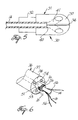
- FIG. 5 is a side view of the split tip electrode of the catheter of FIG. 1.
- FIG. 6 is a cut-away perspective view of the proximal portion of the composite electrode of the catheter of FIG. 1 showing the connection of the electrode lead and safety wires.
- FIG. 7 is a longitudinal cross-sectional view of the catheter tip section of the embodiment of FIGS. 1 to 6 in which the infusion tube comprises two sections.
- FIG. 8 is a longitudinal cross-sectional view of a tip section of a preferred embodiment of the invention which does not comprise a bridge tubing;
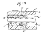
- FIG. 8A is a longitudinal cross-sectional view of a portion of the tip section of FIG. 8 showing a preferred means for anchoring puller wires to the side wall of the tubing of the tip section.
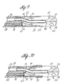
- FIG. 9 is a longitudinal cross-sectinal view of the tip section of a preferred embodiment of the invention in which the split tip electrode does not include a cup electrode.
- FIG. 10 is a longitudinal cross-sectional view of the tip section of another embodiment of the invention similar to FIG. 9 and including a ring electrode on the bridge tubing.
- FIG. 11 is a longitudinal cross-sectional view of the tip section of another preferred embodiment of the invention including an electromagnetic sensor.
- A preferred embodiment of an irrigated split tip electrode catheter constructed in accordance with the present invention is shown in FIGS. 1 - 6. The
catheter 10 comprises an elongated catheter body 11 and atip section 12 at the distal end of the catheter body 11 and acontrol handle 13 at the proximal end of the catheter body 11. - With reference to FIG. 2, the catheter body 11 comprises an elongated tubular construction having a single, central or
axial lumen 25. The catheter body 11 is flexible, i.e., bendable, but substantially non-compressible along its length. The catheter body 11 can be of any suitable construction and made of any suitable material. A presently preferred construction comprises an outer wall 15 made of a polyurethane or the like and an inner stiffening tube 19. The outer wall comprises an imbedded braided mesh of stainless steel or the like to increase torsional stiffness of the catheter body 11 so that, when thecontrol handle 13 is rotated, the tip section of thecatheter 10 will rotate in a corresponding manner. The outer diameter of the catheter body 11 is not critical, but is preferably no more than about 8 french. Likewise the thickness of the outer wall is not critical. - The inner surface of the outer wall is lined with a stiffening tube 19, which can be made of any suitable material, preferably polyimide. The stiffening tube 19, along with the braided outer wall 15, provides improved torsional stability while at the same time minimizing the wall thickness of the catheter, thus maximizing the diameter of the single lumen. The outer diameter of the stiffening tube 19 is about the same as or slightly smaller than the inner diameter of the outer wall. Polyimide tubing is presently preferred because it may be very thin walled while still providing very good stiffness. This maximizes the diameter of the central lumen without sacrificing strength and stiffness.
- A particularly preferred catheter body 11 has an outer wall with an outer diameter of about 0.092 inch and an inner diameter of about 0.063 inch and a polyimide stiffening tube having an outer diameter of about 0.061 inch and an inner diameter of about 0.052 inch.
- As shown in FIG. 2, extending through the lumen are an
infusion tube 14, a plurality ofelectrode lead wires 16, having an insulation coating, and a compression coil 17 in surrounding relation to apuller wire 18. - An enlarged side view of the
tip section 12 is shown in FIGs. 3 and 4. The tip section comprises asplit tip electrode 20 comprising a "quad" tip electrode, i.e. a four membertip electrode assembly 30 and acup electrode 36. Thetip section 12 further comprises abridge tubing 22 and a section offlexible tubing 24. Thetubing 24 is made of a suitable non-toxic material which is preferably more flexible than the catheter body 11. A presently preferred material for thetubing 24 is braided polyurethane, i.e., polyurethane with an embedded mesh of braided stainless steel or the like. The outer diameter of thetip section 12, like that of the catheter body 11, is preferably no greater than about 8 french. The proximal end of theflexible tubing 24 is attached to the distal end of the catheter body 11 by any suitable means. One such means is described in U.S. Patent No. 08/924,339 to Ponzi, which is incorporated herein by reference. - In the embodiment shown, the
flexible tubing 24 has three off axis lumens, afirst lumen 26 through which theinfusion tube 14 extends, asecond lumen 27 through which theelectrode lead wires 16 extend and athird lumen 28 through which thepuller wire 18 extends. The diameter of the three lumens may be the same or may differ a desired. The presently preferred diameters of the first, second and third lumens are about 0.035 inch, about 0.022 inch and about 0.022 inch. The length of the flexible tubing is not critical but is preferably about 2 to 3 inches. The distal end of the flexible tubing is recessed or stepped down to form adistal stem 29 which fits into the proximal end of thebridge tubing 22. - With reference to FIG. 4, the
quad tip electrode 30 has adistal portion 31 having an exterior surface with a preferably rounded or bullet shaped distal end, and aproximal portion 32 which forms a recessed stem. The outer diameter of thedistal portion 31 is preferably 8 french or less. The overall length of the distal portion is not critical but is sufficient for ablation. A presently preferred length is about 2.5 mm. - The
quad tip electrode 30 comprises a fourelectrode members 33. Eachelectrode member 33 comprises a pair of flat interior surfaces and an exterior surface. Theelectrode members 33 are arranged with each flat side of each electrode member adjacent to a flat side of another electrode member, separated therefrom byinsulation 34, preferably high-temperature epoxy. To facilitate the connection of electrode and leadwires 16, eachelectrode member 33 further comprises an electrode lead bore 42 in its proximal end generally parallel to the axis of the catheter body 11. - Each of the
electrode members 33 can be of any suitable construction and is preferably made of platinum. It is understood that the number, shape and various dimensions of theelectrode members 33 are not critical and may be varied as desired. - The
cup electrode 36 is hollow and comprises a generallycylindrical side wall 37 and a generally flatproximal end wall 38. The distal portion of theside 37 wall has anexterior surface 39 forming a ring electrode. The proximal portion of theside wall 37 is recessed. Thestem 32 of thequad tip electrode 30 is received and secured within the hollow interior of thecup electrode 36, by polyurethane glue or the like which electrically insulates thecomposite tip electrode 30 from thecup electrode 36. - The
quad tip electrode 30 comprises acentral irrigation channel 40, formed, for example by drilling, for receiving the distal end of theinfusion tube 14. Thecentral irrigation channel 40 extends axially from the proximal end of thequad tip electrode 30 to about the midpoint of thequad tip electrode 30. There, thechannel 40 divides into four generallytransverse branches 41, each branch extending distally and radially, e.g., at a 45 ° angle, through aseparate electrode member 33. The diameters of thecentral channel 40 andbranches 41 are not critical. A presently preferred composite tip electrode has acentral irrigation channel 40 having a diameter of about 0.5 mm and fourbranches 41, each having a diameter of about 0.4 mm. - It is to be understood that the size and number of channels and/or branches may vary as desired. For example, each electrode member may have a plurality of branches rather than a single branch. Each branch may comprise secondary branches if desired. Rather than defined branches, the electrode members may be made of a porous material, e.g. as described in U.S. Patent Nos. 5,643,197, and 5,462,521, which are incorporated herein by reference.
- If desired, less than all of the electrode members may have irrigation branches or channels. For example, if only one or two of the
electrode members 33 are intended for delivering RF energy during an ablation procedure, it may be desired that only those electrodemembers 33 comprise irrigation branches or channels. - The
cup electrode 36 comprises a plurality of pass-through bores 54 for allowing insulatedelectrode lead wires 16 for each of theelectrode members 33 of thequad tip electrode 30 to pass through theproximal end wall 38 of thecup electrode 36 when the electrode catheter is fully assembled. Each of the pass-through bores 54 are generally parallel to the axis of the catheter body 11, are aligned with an associated electrode lead bore 42, and are equally spaced about the proximal end of thecup electrode 36. To further insulate thecup electrode 36 from thequad tip electrode 30, each of the pass-through bores 54 has a meniscus insulator with a hole defined therethrough, as shown and described in U.S. patent application Serial No. 08/726,380 to Webster, Jr., which is incorporated herein by reference. The meniscus insulator precludes the electrical contact of the associatedelectrode lead wire 16 with thecup electrode 36. - In the embodiment shown, the
cup electrode 36 further comprises an axial hole with a proximally extendingcylindrical flange 51 around the hole. The distal portion of theinfusion tube 14 extends through theflange 51 and axial hole and into thecentral irrigation channel 40 of thequad tip electrode 30 where it is fixedly secured by polyurethane glue or the like. - The
flange 51 has atransverse hole 53 at about its mid-point. Anelectrode lead wire 16 and a pair ofsafety wires 56 are fixedly attached to thestem 51 of thecup electrode 36. A preferred method of attaching theelectrode lead wire 16 andsafety wires 56 is shown in FIG. 6. Theelectrode lead wire 16 andsafety wires 56 are inserted into theflange 51, passed out through thehole 53 and wrapped, preferably one and one-half times, around theflange 51. They are then soldered into place. The proximal end of the safety wires may be secured e.g. by polyurethane glue or the like anywhere in thetip section 12 proximal to thebridge tubing 22. - The
cup electrode 36 can be of any suitable construction and is preferably made of platinum. The dimensions of the cup electrode are not critical. In a presently preferred embodiment, the length of thecup electrode 33 is about 0.13 inch, the depth of the cavity 50 is about 0.08 inch, the outer diameter about 0.09 inch with a cavity diameter of about 0.08 inches. - The
bridge tubing 22 is made of a short section of rigid tubular plastic, preferably PEEK (polyetheretherketone), and has an outer diameter about the same as the outer diameter of the distal portion of thequad tip electrode 30 andflexible tubing 24 of thetip section 12 and an inner diameter about the same as the recessed proximal portion of thecup electrode 36 and the recessed distal potion of theflexible tubing 24. Thebridge tubing 22 connects thesplit tip electrode 20 to theflexible tubing 24. At its distal end, thebridge tubing 22 receives the recessed proximal portion of thecup electrode 36 which is secured therein by polyurethane glue or the like. At its proximal end, thebridge tubing 22 receives the recessed distal end of theflexible tubing 24 which is also secured therein by polyurethane glue or the like. - The length of the
bridge tubing 22 is selected to provide a gap within the interior of thebridge tubing 22 between the proximal end of thecup electrode 36 and the distal end of theflexible tubing 24. The gap is sufficiently long to allow space for theinfusion tube 14 to bend or curve from the off-axis lumen 26 in theflexible tubing 24 into alignment with the axial hole andflange 51 in thecup electrode 33. Theelectrode lead wires 16 extend out of off-axis lumen 27 in theflexible tubing 24 to separate pass-through bores 54 in thecup electrode 36 and to theflange 51 of thecup electrode 33. Abridge tubing 22 having a length of about 6 to about 7 mm and providing a gap of about 1 to about 2 mm is presently preferred. It is understood that the bridge tubing may be made of any suitable, generally rigid plastic which can withstand the temperature reached during an ablation procedure without significant, i.e., detrimental, deformation. - The
infusion tube 14 may be made of any suitable material. Polyimide is presently preferred. It may be a single elongated tube which extends through the catheter body 11 through thefirst lumen 26 of thetip section 12, though thebridge tubing 22 andcup electrode 36 and into theirrigation channel 40 of the quad tip electrode. Alternatively, as shown in Fig. 7, theinfusion tube 14 may comprise two sections, a proximal section which extends through the catheter body 11 and into the proximal end of thefirst lumen 26 of the tip section, the distal end of the proximal infusion tube section being secured in thefirst lumen 26 by polyurethane glue or the like. A second section of the infusion tube extends from the distal end of thefirst lumen 26 of thetip section 12, where it is secured by polyurethane glue or the like through thebridge tubing 22 andflange 51 of thecup electrode 36 and into thecentral irrigation channel 40 of the quad tip electrode. - The proximal end of the
infusion tube 14 extends out of a sealed opening in the side wall of the catheter body and terminates in a Luer hub or the like. Alternatively, theinfusion tube 14 may extend through the control handle 13 and terminate in a luer hub or the like at a location proximal to the handle. In either such arrangement, fluids, e.g., saline may be introduced into and passed through theinfusion tube 14 and into and through theelectrode members 33 of thecomposite tip 30 to cool theelectrode members 33 during an ablation procedure. It is understood that other fluids, e.g., drugs, may also be passed through the infusion tube and out composite tip if desired. In a particularly preferred embodiment, the infusion tube is made out of thin walled polyamide tubing. It is understood that any suitable material may be used. Preferably having an outer diameter about the same as or slightly smaller than the diameter of thefirst lumen 26 of thetip section 12. - In a preferred embodiment, the
electrode lead wires 16 associated with eachelectrode member 33 of thecomposite tip electrode 36 andcup electrode 36 is one wire of a pair of wires of dissimilar metals. The presently preferred wire pair is an enameled copper constantan wire pair comprising a copper wire, having a thickness of about 0.003" and a constantan/wire, having a thickness of about 0.003", enameled to the copper wire. Such an enameled wire pair is described in U.S. Patent Application Serial No. 08/742,352 to Webster, Jr. which is incorporated herein by reference. In this configuration, the constantan wire, which has high strength supports the copper wire which is soft and fragile. Because the leads are constructed out of two different types of wire, the leads also serve as a thermocouple for measuring the temperature of the electrode. It is understood that any temperature monitoring means, e.g., a themistor, a wire pair used exclusively as a thermocouple, may be used as desired. The leads 16 may also be used to interrupt power delivery in case of irrigation failure. The leads 16 extend into the electrode lead bores 42 of theelectrode members 33 and are fixedly attached thereto by any suitable means, e.g., soldering or welding. - If desired, the irrigated split tip catheter of the present invention may comprise one or
more ring electrodes 58 as shown, for example in Fig. 3. Attachment of electrode lead wires to such ring electrodes may be accomplished by any suitable means and/or procedure. A presently preferred procedure for attaching electrode leads to a ring electrode is described in U.S. Patent Application Serial No. 08/742,352 to Webster, Jr. - The
puller wire 18 extends from the control handle 13 through thelumen 20 of the catheter body 11 and into the thirdoff axis lumen 28 of theflexible tubing 24 of thetip section 12. Thepuller wire 18 is made of any suitable metal, such as stainless steel or Nitinol, and is preferably coated with Teflon® or the like. The coating imparts lubricity to thepuller wire 18. Thepuller wire 18 preferably has a diameter ranging from about 0.006 to about 0.010 inches. The distal end of thepuller wire 18 is anchored at or about the distal end of theflexible tubing 24 by any applicable means. A presently preferred means for anchoring the distal end of the puller wire is described in U.S. Patent Application Nos. 09/134,009 and 09/099,769 to Webster, Jr., both of which are incorporated herein by reference. Briefly, thepuller wire 18 comprises a T-bar anchor which is fixedly attached to the distal end of the puller wire. The crossbar of the T-bar anchor lies outside of the distal end of the third off-axis lumen of the flexible tubing or in a notch created in the side wall of the flexible tubing which communicates with the third lumen. The size of the crossbar is selected so that it cannot be pulled into the third lumen. In this arrangement pulling on the puller wire results in deflection of the flexible tubing of the tip section in the direction of the third lumen. It is understood that the T-bar anchor may be secured in the notch in the side wall of the tip section tubing, if desired, as described in the above-mentioned U.S. Patent Application Nos. 09/134,009 and 09/009,769. Alternatively, the puller wire may be soldered or welded to the cup electrode. - To prevent deflection of the catheter body when the puller wire is pulled, there is provided a compression coil 17 in surrounding relation to the portion of the puller wire extending through the catheter body. The compression coil 17 extends from the proximal end of the catheter body 11 to the distal end of the catheter body 19 or the proximal end of the
tip section 12. The compression coil 17 may be made from any suitable material, but is preferably made from stainless steel. The compression coil 17 is tightly wound on itself to provide flexibility, i.e., bending, but to resist compression. The inner diameter of the compression coil is slightly larger than the diameter of the puller wire. For example, when thepuller wire 18 has a diameter of about 0.007 inches, the compression coil 17 preferably has an inner diameter of about 0.008 inches. The Teflon® coating of thepuller wire 18 allows it to slide freely within the compression coil 17. Along its length, the outer surface of the compression coil is covered by a flexible, nonconductive sheath to prevent contact between the compression coil 17 and any of thelead wires 16. A nonconductive sheath made of polyimide tubing is presently preferred. Such an arrangement involving a compression coil in surrounding relation to a puller wire is described in U.S. Patent Application No. 08/982,667 to Klumb, et al, filed on December 12, 1997 which is incorporated fully herein by reference. - The compression coil 17 is preferably anchored at its proximal end to the proximal end of the stiffening tube in the catheter body 11 by a glue joint and at its distal end to the distal of the catheter body 11 or the proximal end of the
tip section 12, by another glue joint. Both glue joints are preferably comprised of polyurethane glue or the like. - Longitudinal movement of the puller wire is controlled by
control handle 13. The control handle may be of any suitable design. A presently preferred control handle for a single puller wire is disclosed in U.S. Patent No. Re 34,502 to Webster, Jr. which is incorporated herein by reference. Such a handle is particularly applicable if the proximal end of the infusion tube extends out of the catheter body terminating in a Luer hub or the like. Alternatively, if the infusion tube extends through the control handle, a control handle as described in U.S. Patent application Serial No. 08/924,339, which is incorporated hereby by reference, is preferred. - In another embodiment of the invention as shown in FIG. 8 and FIG. 8A, the
tip section 12 comprises splittip electrode 20 which is attached directly to theflexible tubing 24. That is, there is no bridge tubing. In this embodiment, the split tip electrode comprises a quad tip electrode as described above. Thecup electrode 36 comprises a cylindrical side wall having an exterior surface forming a ring electrode. However, in this embodiment, there is no recessed proximal portion of the sidewall. That is, the entire sidewall of thecup electrode 36 forms a ring electrode. - The
flexible tubing 24 comprises five lumens, 4 symmetrically spaced off-axis lumens 61 and anaxial lumen 62. Theflexible tubing 24 comprises anaxial bore 63 at its distal end having a diameter slightly larger than the outer diameter of thecylindrical flange 51 of thecup electrode 36 to accommodate thesafety wires 56 and cupelectrode lead wire 16 which is wrapped around the outer circumference of thecylindrical flange 51. If desired, the distal ends of thesafety wires 56 may be flattened to reduce the diameter of the trepannedhole 63 in theflexible tubing 24 needed to accomodate thecylindrical flange 51 andsafety wires 56 wrapped thereabout. - The
infusion tube 14 extends through theaxial lumen 62 of theflexible tubing 24, through theflange 51 of thecup electrode 36 and directly into thecentral irrigation channel 40 of the quad tip electrode. As described above, the infusion tube may be a single elongated tube or may comprise discrete proximal and distal sections. - The
electrode lead wires 16, preferably enameled wire pairs as described above, for theelectrode members 33 of the quad tip electrode extends through one (or more) of the off-axis lumens 62. Asmall gap 64 is provided between the distal end of theflexible tubing 24 and the proximal end plate of thecup electrode 36. Within thisgap 64, theelectrode lead wires 16 which are not aligned with a pass through bore in thecup electrode 36 may pass from the off-axis lumen(s) 61 to pass through bores 54 of thecup electrode 36 and then into the electrode lead bores 42 of theelectrode members 33 of thequad tip electrode 30 where they are fixedly attached. - In this embodiment, there are two
puller wires 18 which extend through the catheter body 11 and into diametrically opposed off-axis lumens 61 in theflexible tubing 24. The distal ends of thepuller wires 18 preferably comprise T-bar anchors 65 as described above and are preferably anchored byglue 66 innotches 67 in the side wall of theflexible tubing 24 as shown in Fig. 8A and as described in U.S. Patent Application Nos. 09/134,009 and 09/099,769. Alternatively, the distal ends of the puller wires may be soldered or welded directly to the proximal end plate of thecup electrode 36. - The
cup electrode 36 is fixedly secured to the distal end of theflexible tubing 24 by polyurethane glue or the like which fills thegap 64. - In yet another embodiment of the invention shown in FIG. 9, the tip section comprises a section of
flexible tubing 24, abridge tubing 22 and thesplit tip electrode 20 comprises a quad tip electrode, but no cup electrode. In such an embodiment, the recessedstem 32 of the quad tip electrode extends directly into the distal end of thebridge tubing 22 and is secured therein by polyurethane glue or the like. - At its proximal end, the
bridge tubing 22 receives the recessed distal end of theflexible tubing 24. Theflexible tubing 24 preferably comprises three off-axis lumens, as described with respect to the embodiment of FIGS. 1-7, through which aninfusion tube 14,electrode lead wires 16 and apuller wire 18 extend. It is understood that, if desired, three lumenflexible tubing 24 may be used in which all lumens are diametrically aligned. A three off-axis lumen is preferred, however, because it provides superior strength. If bidirectional capability is desired, the flexible tubing preferably comprises four off-axis lumens, and thepuller wires 18 extending through diametrically opposed off-axis lumens. - If desired, an electrically
isolated ring electrode 58 may be mounted around the distal end of thebridge tubing 22 as shown in FIG. 10. In such an embodiment, the lead wire for the ring electrode extends through a small hole in thebridge tubing 22 and across the exterior surface of the bridge tubing to theelectrode 58. The lead wire is covered and the hole in the bridge tubing is filled with polyurethane resin or the like. More than one ring electrodes may be carried by the bridge tubing or the flexible tubing. - In a further embodiment of the invention as shown in FIG. 11, the
tip section 12 carries anelectromagnetic sensor 71 within thebridge tubing 22. In this embodiment, thesplit tip electrode 20 may (as shown) or may not comprise acup electrode 36, as desired. Theflexible tubing 24 comprises at least three off-axis lumens, one for acable 72 which extends from theelectromagnetic sensor 71 through thetip section 12, catheter body 11 and handle 13 to a connector for connection to a signal processing and imaging means. If desired, a circuit board can be provided in the control handle. The sensor cable is connected to the circuit board, which amplifies the signal received from the electromagnetic sensor and transmits it to a computer in a form understandable by the computer. The other two lumens in the flexible tubing are for theinfusion tube 14 and electrode lead wires (not shown) and for a puller wire (not shown). Again, if bidirectional capability is desired, a fourth off-axis lumen in the flexible tubing would be required for the second puller wire. Suitable electromagnetic sensors and signal processing and imaging means are commercially available from Cordis Webster, Inc., and are described in U.S. Patent Nos. 5,558,091, 5,443,489, 5,480,422, 5,546,951, 5,568,809, and 5,391,199 and International Publication No. WO95/02995 which are incorporated herein by reference. - In this embodiment, the
bridge tubing 22 is sufficiently long to allow theinfusion tube 14 to curve around theelectromagnetic sensor 71 and into theaxial flange 51 of thecup electrode 36 into thecentral irrigation channel 40 in the quad tip electrode. - It is to be understood that, with respect to the embodiments described above comprising a single puller wire, the catheter may comprise two or more puller wires. Likewise, those embodiments described above comprising a pair of puller wires may, if desired, comprise only a single puller wire. In an embodiment comprising a pair of puller wires, the
flexible tubing 24 of thetip section 12 would preferably comprise four off-axis lumens. The puller wires would preferably extend into diametrically opposed off axis lumens and be anchored at the distal end of the flexible tubing as described above. Control handles for manipulating a pair of puller wires are well known. Preferred control handles are described in U.S. Patent Nos. Re 34,502 to Webster, Jr., and U.S. Patent Application Serial Nos. 08/924,611, 08/982,113, 09/134,009, and 09/143,426 to Webster, Jr., and 09/130,359 to Ponzi, all of which are incorporated herein by reference. - In the event that an omni-directional capability is desired, the catheter may comprise three or more, and preferably four puller wires. In such an embodiment, the flexible tubing of the tip section would preferably comprise four off-axis lumens, one in each quadrant, through which the puller wires extend. A central lumen in the tip section would preferably be provided to accommodate the infusion tube and electrode lead wires. Such an arrangement of lumens and puller wires and a control handle for manipulating the puller wires is disclosed in U.S. Patent Application Serial No. 08/924,611 to Webster, Jr., which is incorporated herein by reference.
- It is to be understood that any suitable means for controllably deflecting the tip section in one or more may be used. Examples of other such means can be found in U.S. Patent Nos. 5,656,030 to Hunjan, et al, 5,195,968, 5,254,088, 5336,189, 5,531,686 to Lundquist, et al, 5,273,535,5,281,217,5,370,678 to Edwards, et al, 5,358,478 to Thompson, et al, 5,364,351 and 5,456,664 to Hemzelman, all of which are incorporated herein by reference.
- It is understood that any construction providing a split tip electrode comprising two or more electrode members may be used in this invention. The presence of a cup electrode, while preferred is not required. Likewise, the presence of a bridge tubing is preferred, but not required.
- The irrigated split tip electrode catheter of the present invention can be used to sense, i.e., map, the electrical pathways of the heart, both speed and direction, locate aberrant pathways and to interrupt those aberrant pathways by delivering RF energy to the aberrant pathway through one or more electrode members of the composite tip electrode to ablate the tissue thereat. During ablation, the RF delivery electrode members and the interface between the electrode members and the myocardium or blood are cooled to avoid the formation of coagulum on the electrode surface by passing a fluid, e.g., saline solution, through the infusion tube and the composite tip electrode. A particularly preferred method for using the described irrigated split tip catheters is disclosed in concurrently filed European patent application No. , claiming priority from USSN 09/205 628 (Attorney's ref P023332EP), which is incorporated herein by reference.
- The preceding description has been presented with reference to presently preferred embodiments of the invention. Workers skilled in the art and technology to which this invention pertains will appreciate that alterations and changes in the described structure may be practiced without meaningfully departing from the principal, spirit and scope of this invention.
- Accordingly, the foregoing description should not be read as pertaining only to the precise structures described and illustrated in the accompanying drawings, but rather should be read consistent with and as support to the following claims which are to have their fullest and fair scope.
Claims (10)
- An irrigated split tip electrode catheter, comprising:an elongated catheter body having a proximal and distal end and at least one lumen extending therethrough;a catheter tip section extending from the distal end of the catheter body, the catheter tip section comprising a:flexible tubing having at least one lumen therethrough;a split-tip electrode comprising a tip electrode assembly including at least two adjacent, electrically isolated electrode members fixedly attached at the distal end of the tip section; andmeans for fixedly connecting the split-tip electrode to the distal end of the flexible tubing;an electrode lead wire electrically connected to each electrode member of the composite tip electrode, each such electrode lead wire extending through a lumen in the catheter tip section and catheter body to the proximal end of the catheter;means for passing a fluid through the catheter body, tip section and at least one electrode member of the tip electrode assembly;means for controllably deflecting the tip section.
- A catheter as recited in claim 1 wherein the means for passing a fluid through the catheter body, tip section and at least one electrode member of the tip electrode assembly comprises an infusion tube which extends through the catheter body and tip section, an irrigation channel through at least one electrode member of the tip electrode assembly, said channel being in communication with the infusion tube and means at the proximal end of the infusion tube for introducing a fluid into and through the infusion tube and the irrigation channel of the at least one electrode member.
- A catheter as recited in claim 2 wherein the electrode tip electrode assembly comprises an axial irrigation channel which extends distally from the proximal end of the tip electrode assembly a portion of the length of the tip electrode assembly and wherein at least one electrode member comprises an irrigation channel which branches off from the axial irrigation channel and extends through the electrode member and wherein the infusion tube is in communication with the axial irrigation channel.
- A catheter as recited in claim 3 wherein each electrode member of the tip electrode assembly comprises an irrigation channel which branches off of the axial irrigation channel and extends through said electrode member.
- A catheter as recited in claim 1 wherein at least one electrode member is formed from a porous material.
- A catheter as recited in claim 1 wherein the fixedly connecting means comprises a hollow bridge tubing connecting and defining a gap between the distal end of the flexible tubing and the proximal end of the tip electrode assembly.
- A catheter as recited in claim 1 further comprising a means for sensing the temperature of at least one electrode member.
- A catheter as recited in claim 7 wherein the temperature sensing means comprises a wire pair associated with each electrode member of the tip electrode assembly, each said wire pair comprising a pair of wires of dissimilar metals enameled together along their length, each wire of each such wire pair extending through the catheter body and flexible tubing of the tip section and being electrically connected to its associated electrode member.
- A catheter as recited in claim 8 wherein one wire of each wire pair functions as an electrode lead wire.
- A catheter as recited in claim 1 wherein the catheter body comprises a single axial lumen.
Applications Claiming Priority (2)
| Application Number | Priority Date | Filing Date | Title |
|---|---|---|---|
| US205116 | 1998-12-03 | ||
| US09/205,116 US6171275B1 (en) | 1998-12-03 | 1998-12-03 | Irrigated split tip electrode catheter |
Publications (3)
| Publication Number | Publication Date |
|---|---|
| EP1008327A2 true EP1008327A2 (en) | 2000-06-14 |
| EP1008327A3 EP1008327A3 (en) | 2002-08-21 |
| EP1008327B1 EP1008327B1 (en) | 2008-10-01 |
Family
ID=22760862
Family Applications (1)
| Application Number | Title | Priority Date | Filing Date |
|---|---|---|---|
| EP99309683A Expired - Lifetime EP1008327B1 (en) | 1998-12-03 | 1999-12-02 | Irrigated split tip electrode catheter |
Country Status (5)
| Country | Link |
|---|---|
| US (1) | US6171275B1 (en) |
| EP (1) | EP1008327B1 (en) |
| JP (1) | JP4156156B2 (en) |
| AT (1) | ATE409440T1 (en) |
| DE (1) | DE69939641D1 (en) |
Cited By (20)
| Publication number | Priority date | Publication date | Assignee | Title |
|---|---|---|---|---|
| EP1389447A1 (en) * | 2002-08-16 | 2004-02-18 | Cryocor, Inc. | Heat transfer segment for a cryoblation cathether |
| WO2004039272A1 (en) * | 2002-05-29 | 2004-05-13 | Celon Ag Medical Instruments | High frequency application device |
| EP1514523A1 (en) | 2003-09-11 | 2005-03-16 | Biotronik GmbH & Co. KG | Catheter |
| DE102004009545A1 (en) * | 2004-02-24 | 2005-09-08 | Filt Lungen- Und Thoraxdiagnostik Gmbh | Sampling method for exhaled air, urine or blood, whereby a cooled probe is placed in the flow that is to be examined so that water vapor and any other substances of interest condense out |
| WO2005112814A3 (en) * | 2004-05-17 | 2006-04-06 | Bard Inc C R | Irrigated catheter |
| EP2213257A3 (en) * | 2003-03-28 | 2010-09-29 | C. R. Bard, Inc. | Braided Mesh Catheter |
| WO2014029355A1 (en) * | 2012-08-24 | 2014-02-27 | Symap Medical (Suzhou) , Ltd | Device for mapping and ablating renal nerves distributed on the renal artery |
| CN104622567A (en) * | 2013-11-15 | 2015-05-20 | 上海微创电生理医疗科技有限公司 | Ablation electrode and medical catheter with same |
| WO2015112494A1 (en) * | 2014-01-23 | 2015-07-30 | St. Jude Medical, Cardiology Division, Inc. | Medical devices including high strength bond joints and methods of making same |
| US9375154B2 (en) | 2011-08-26 | 2016-06-28 | Symap Medical (Suzhou), Ltd | System and method for locating and identifying the functional nerves innervating the wall of arteries and catheters for same |
| US9636164B2 (en) | 2015-03-25 | 2017-05-02 | Advanced Cardiac Therapeutics, Inc. | Contact sensing systems and methods |
| US9820811B2 (en) | 2011-08-26 | 2017-11-21 | Symap Medical (Suzhou), Ltd | System and method for mapping the functional nerves innervating the wall of arteries, 3-D mapping and catheters for same |
| EP3417821A1 (en) * | 2013-10-28 | 2018-12-26 | St. Jude Medical, Cardiology Division, Inc. | Ablation catheter designs and methods with enhanced diagnostic capabilities |
| US10383686B2 (en) | 2014-11-19 | 2019-08-20 | Epix Therapeutics, Inc. | Ablation systems with multiple temperature sensors |
| US10413212B2 (en) | 2014-11-19 | 2019-09-17 | Epix Therapeutics, Inc. | Methods and systems for enhanced mapping of tissue |
| US10888373B2 (en) | 2017-04-27 | 2021-01-12 | Epix Therapeutics, Inc. | Contact assessment between an ablation catheter and tissue |
| US11179197B2 (en) | 2016-03-15 | 2021-11-23 | Epix Therapeutics, Inc. | Methods of determining catheter orientation |
| US11324408B2 (en) | 2011-08-26 | 2022-05-10 | Symap Medical (Suzhou), Ltd | Mapping sympathetic nerve distribution for renal ablation and catheters for same |
| US11534227B2 (en) | 2014-11-19 | 2022-12-27 | Epix Therapeutics, Inc. | High-resolution mapping of tissue with pacing |
| US11832965B2 (en) | 2018-10-06 | 2023-12-05 | Symap Medical (Suzhou), Limited | System and method for mapping the functional nerves innervating the wall of arteries, 3-D mapping and catheters for same |
Families Citing this family (109)
| Publication number | Priority date | Publication date | Assignee | Title |
|---|---|---|---|---|
| US7175619B2 (en) * | 1994-10-07 | 2007-02-13 | Boston Scientific Scimed, Inc. | Loop structures for positioning a diagnostic or therapeutic element on the epicardium or other organ surface |
| US6464700B1 (en) | 1994-10-07 | 2002-10-15 | Scimed Life Systems, Inc. | Loop structures for positioning a diagnostic or therapeutic element on the epicardium or other organ surface |
| US6645200B1 (en) * | 1997-10-10 | 2003-11-11 | Scimed Life Systems, Inc. | Method and apparatus for positioning a diagnostic or therapeutic element within the body and tip electrode for use with same |
| US6466818B1 (en) * | 1999-01-15 | 2002-10-15 | Biosense Webster, Inc. | Porous irrigated tip electrode catheter |
| US6689131B2 (en) | 2001-03-08 | 2004-02-10 | Tissuelink Medical, Inc. | Electrosurgical device having a tissue reduction sensor |
| US6558385B1 (en) | 2000-09-22 | 2003-05-06 | Tissuelink Medical, Inc. | Fluid-assisted medical device |
| ES2643763T3 (en) * | 2000-03-06 | 2017-11-24 | Salient Surgical Technologies, Inc. | Fluid supply system and controller for electrosurgical devices |
| US7811282B2 (en) | 2000-03-06 | 2010-10-12 | Salient Surgical Technologies, Inc. | Fluid-assisted electrosurgical devices, electrosurgical unit with pump and methods of use thereof |
| US8048070B2 (en) * | 2000-03-06 | 2011-11-01 | Salient Surgical Technologies, Inc. | Fluid-assisted medical devices, systems and methods |
| US6477396B1 (en) * | 2000-07-07 | 2002-11-05 | Biosense Webster, Inc. | Mapping and ablation catheter |
| US6863678B2 (en) * | 2001-09-19 | 2005-03-08 | Advanced Cardiovascular Systems, Inc. | Catheter with a multilayered shaft section having a polyimide layer |
| US6979342B2 (en) | 2001-09-19 | 2005-12-27 | Advanced Cardiovascular Systems, Incc | Catheter with a polyimide distal tip |
| US7037291B2 (en) * | 2001-12-04 | 2006-05-02 | Advanced Cardiovascular Systems, Inc. | Catheter shaft junction having a polymeric reinforcing member with a high glass transition temperature |
| AU2002357166A1 (en) * | 2001-12-12 | 2003-06-23 | Tissuelink Medical, Inc. | Fluid-assisted medical devices, systems and methods |
| US7070642B2 (en) * | 2002-10-28 | 2006-07-04 | Donaldson Company, Inc. | Air cleaner; replaceable filter cartridges; and, methods |
| AU2003288945A1 (en) | 2002-10-29 | 2004-05-25 | Tissuelink Medical, Inc. | Fluid-assisted electrosurgical scissors and methods |
| US6984232B2 (en) * | 2003-01-17 | 2006-01-10 | St. Jude Medical, Daig Division, Inc. | Ablation catheter assembly having a virtual electrode comprising portholes |
| US7387629B2 (en) * | 2003-01-21 | 2008-06-17 | St. Jude Medical, Atrial Fibrillation Division, Inc. | Catheter design that facilitates positioning at tissue to be diagnosed or treated |
| US7819866B2 (en) | 2003-01-21 | 2010-10-26 | St. Jude Medical, Atrial Fibrillation Division, Inc. | Ablation catheter and electrode |
| US6960207B2 (en) * | 2003-01-21 | 2005-11-01 | St Jude Medical, Daig Division, Inc. | Ablation catheter having a virtual electrode comprising portholes and a porous conductor |
| US20040267203A1 (en) * | 2003-06-26 | 2004-12-30 | Potter Daniel J. | Splittable cannula having radiopaque marker |
| US7101362B2 (en) * | 2003-07-02 | 2006-09-05 | St. Jude Medical, Atrial Fibrillation Division, Inc. | Steerable and shapable catheter employing fluid force |
| US7789877B2 (en) | 2003-07-02 | 2010-09-07 | St. Jude Medical, Atrial Fibrillation Division, Inc. | Ablation catheter electrode arrangement |
| US7235070B2 (en) * | 2003-07-02 | 2007-06-26 | St. Jude Medical, Atrial Fibrillation Division, Inc. | Ablation fluid manifold for ablation catheter |
| US7678104B2 (en) | 2003-07-17 | 2010-03-16 | Biosense Webster, Inc. | Ultrasound ablation catheter and method for its use |
| US7104989B2 (en) * | 2003-09-05 | 2006-09-12 | Medtronic, Inc. | RF ablation catheter including a virtual electrode assembly |
| NL1024658C2 (en) * | 2003-10-29 | 2005-05-02 | Univ Medisch Centrum Utrecht | Catheter and method, in particular for ablation and the like. |
| US20050267467A1 (en) * | 2004-01-16 | 2005-12-01 | Saurav Paul | Bipolar conforming electrode catheter and methods for ablation |
| US7727232B1 (en) | 2004-02-04 | 2010-06-01 | Salient Surgical Technologies, Inc. | Fluid-assisted medical devices and methods |
| US20060004316A1 (en) * | 2004-07-02 | 2006-01-05 | Difiore Attilio E | Reduction of recirculation in catheters |
| US7918851B2 (en) * | 2005-02-14 | 2011-04-05 | Biosense Webster, Inc. | Irrigated tip catheter and method for manufacturing therefor |
| US8075498B2 (en) | 2005-03-04 | 2011-12-13 | Endosense Sa | Medical apparatus system having optical fiber load sensing capability |
| US8182433B2 (en) * | 2005-03-04 | 2012-05-22 | Endosense Sa | Medical apparatus system having optical fiber load sensing capability |
| US7857810B2 (en) * | 2006-05-16 | 2010-12-28 | St. Jude Medical, Atrial Fibrillation Division, Inc. | Ablation electrode assembly and methods for improved control of temperature and minimization of coagulation and tissue damage |
| US8128621B2 (en) | 2005-05-16 | 2012-03-06 | St. Jude Medical, Atrial Fibrillation Division, Inc. | Irrigated ablation electrode assembly and method for control of temperature |
| US20080091193A1 (en) * | 2005-05-16 | 2008-04-17 | James Kauphusman | Irrigated ablation catheter having magnetic tip for magnetic field control and guidance |
| US7776034B2 (en) * | 2005-06-15 | 2010-08-17 | St. Jude Medical, Atrial Fibrillation Division, Inc. | Ablation catheter with adjustable virtual electrode |
| US7419486B2 (en) * | 2005-06-15 | 2008-09-02 | St. Jude Medical, Atrial Fibrillation Division, Inc. | Treatment and diagnostic catheters with hydrogel electrodes |
| US7819868B2 (en) | 2005-06-21 | 2010-10-26 | St. Jude Medical, Atrial Fibrilation Division, Inc. | Ablation catheter with fluid distribution structures |
| US7879030B2 (en) | 2005-07-27 | 2011-02-01 | St. Jude Medical, Atrial Fibrillation Division, Inc. | Multipolar, virtual-electrode catheter with at least one surface electrode and method for ablation |
| EP3028645B1 (en) | 2005-08-01 | 2019-09-18 | St. Jude Medical International Holding S.à r.l. | Medical apparatus system having optical fiber load sensing capability |
| US8628520B2 (en) | 2006-05-02 | 2014-01-14 | Biosense Webster, Inc. | Catheter with omni-directional optical lesion evaluation |
| US7774051B2 (en) * | 2006-05-17 | 2010-08-10 | St. Jude Medical, Atrial Fibrillation Division, Inc. | System and method for mapping electrophysiology information onto complex geometry |
| US8048063B2 (en) * | 2006-06-09 | 2011-11-01 | Endosense Sa | Catheter having tri-axial force sensor |
| US8567265B2 (en) | 2006-06-09 | 2013-10-29 | Endosense, SA | Triaxial fiber optic force sensing catheter |
| US8382738B2 (en) | 2006-06-30 | 2013-02-26 | Abbott Cardiovascular Systems, Inc. | Balloon catheter tapered shaft having high strength and flexibility and method of making same |
| US7906066B2 (en) * | 2006-06-30 | 2011-03-15 | Abbott Cardiovascular Systems, Inc. | Method of making a balloon catheter shaft having high strength and flexibility |
| EP2664372A1 (en) | 2006-10-06 | 2013-11-20 | Donaldson Company, Inc. | Air cleaner, replaceable filter cartridges, and methods |
| US8551085B2 (en) * | 2006-10-10 | 2013-10-08 | St. Jude Medical, Atrial Fibrillation Division, Inc. | Ablation electrode assembly with insulated distal outlet |
| US8986298B2 (en) | 2006-11-17 | 2015-03-24 | Biosense Webster, Inc. | Catheter with omni-directional optical tip having isolated optical paths |
| WO2008124437A2 (en) * | 2007-04-03 | 2008-10-16 | Donaldson Company, Inc. | Air cleaner; air filter cartridge and method of manufacturing |
| US8764742B2 (en) | 2007-04-04 | 2014-07-01 | St. Jude Medical, Atrial Fibrillation Division, Inc. | Irrigated catheter |
| US8979837B2 (en) | 2007-04-04 | 2015-03-17 | St. Jude Medical, Atrial Fibrillation Division, Inc. | Flexible tip catheter with extended fluid lumen |
| US8517999B2 (en) * | 2007-04-04 | 2013-08-27 | St. Jude Medical, Atrial Fibrillation Division, Inc. | Irrigated catheter with improved fluid flow |
| US8641666B2 (en) * | 2007-05-16 | 2014-02-04 | Abbott Cardiovascular Systems Inc. | Catheter with laminar flow drug delivery properties |
| US8157789B2 (en) | 2007-05-24 | 2012-04-17 | Endosense Sa | Touch sensing catheter |
| US8622935B1 (en) | 2007-05-25 | 2014-01-07 | Endosense Sa | Elongated surgical manipulator with body position and distal force sensing |
| US8066791B2 (en) | 2007-07-20 | 2011-11-29 | Donaldson Company, Inc. | Air cleaner arrangements with internal and external support for cartridge; components; and, methods |
| US8292984B2 (en) | 2007-07-20 | 2012-10-23 | Donaldson Company, Inc. | Air cleaner arrangments with end support for cartridge; components; and, methods |
| US9579148B2 (en) * | 2007-11-13 | 2017-02-28 | St. Jude Medical, Atrial Fibrillation Division, Inc. | Irrigated ablation electrode having recessed surface portions |
| US8128620B2 (en) * | 2007-11-13 | 2012-03-06 | St. Jude Medical, Atrial Fibrillation Division, Inc. | Irrigated ablation electrode having proximal direction flow |
| US8500730B2 (en) * | 2007-11-16 | 2013-08-06 | Biosense Webster, Inc. | Catheter with omni-directional optical tip having isolated optical paths |
| US8052684B2 (en) * | 2007-11-30 | 2011-11-08 | St. Jude Medical, Atrial Fibrillation Division, Inc. | Irrigated ablation catheter having parallel external flow and proximally tapered electrode |
| US8403885B2 (en) * | 2007-12-17 | 2013-03-26 | Abbott Cardiovascular Systems Inc. | Catheter having transitioning shaft segments |
| US8221409B2 (en) * | 2007-12-21 | 2012-07-17 | St. Jude Medical, Atrial Fibrillation Division, Inc. | Thermally insulated irrigation catheter assembly |
| US8216225B2 (en) * | 2007-12-21 | 2012-07-10 | St. Jude Medical, Atrial Fibrillation Division, Inc. | Irrigated ablation electrode assembly having a polygonal electrode |
| US8273082B2 (en) | 2007-12-21 | 2012-09-25 | St. Jude Medical, Atrial Fibrillation Division, Inc. | Irrigated ablation catheter assembly having a flow member to create parallel external flow |
| US8298227B2 (en) * | 2008-05-14 | 2012-10-30 | Endosense Sa | Temperature compensated strain sensing catheter |
| US20090312756A1 (en) * | 2008-06-17 | 2009-12-17 | Hansen Medical, Inc. | Irrigated ablation catheters |
| US8882761B2 (en) | 2008-07-15 | 2014-11-11 | Catheffects, Inc. | Catheter and method for improved ablation |
| US8052638B2 (en) | 2008-11-26 | 2011-11-08 | Abbott Cardiovascular Systems, Inc. | Robust multi-layer balloon |
| US8444608B2 (en) * | 2008-11-26 | 2013-05-21 | Abbott Cardivascular Systems, Inc. | Robust catheter tubing |
| US8974453B2 (en) | 2008-12-02 | 2015-03-10 | St. Jude Medical, Atrial Fibrillation Division, Inc. | Irrigated ablation catheter having a flexible manifold |
| US9757189B2 (en) * | 2008-12-03 | 2017-09-12 | Biosense Webster, Inc. | Prevention of kinks in catheter irrigation tubes |
| EP2395934B1 (en) | 2009-02-11 | 2019-04-17 | Boston Scientific Scimed, Inc. | Insulated ablation catheter devices |
| US8864744B2 (en) * | 2009-02-25 | 2014-10-21 | St. Jude Medical, Atrial Fibrillation Division, Inc. | Medical device having laminate-coated braid assembly |
| US8910376B2 (en) * | 2009-05-27 | 2014-12-16 | Boston Scientific Neuromodulation Corporation | Systems and methods for forming an end of an elongated member of an electrical stimulation system |
| US9277961B2 (en) | 2009-06-12 | 2016-03-08 | Advanced Cardiac Therapeutics, Inc. | Systems and methods of radiometrically determining a hot-spot temperature of tissue being treated |
| US9226791B2 (en) | 2012-03-12 | 2016-01-05 | Advanced Cardiac Therapeutics, Inc. | Systems for temperature-controlled ablation using radiometric feedback |
| TWI423602B (en) * | 2009-12-07 | 2014-01-11 | Mediatek Inc | Method of reducing interference between two communication systems operating in adjacent frequency bands |
| US9179968B2 (en) | 2010-05-10 | 2015-11-10 | St. Jude Medical Luxembourg Holding S.À.R.L. | Irrigated finned ablation head |
| US8814857B2 (en) | 2010-12-17 | 2014-08-26 | St. Jude Medical, Atrial Filbrillation Division, Inc. | Irrigated ablation electrode assemblies |
| US8880147B2 (en) * | 2011-05-02 | 2014-11-04 | St. Jude Medical, Atrial Fibrillation Division, Inc. | Sensor assembly tethered within catheter wall |
| WO2012162661A1 (en) | 2011-05-26 | 2012-11-29 | Abbott Cardiovascular Systems Inc. | Through tip for a catheter |
| US20220287770A1 (en) * | 2011-08-26 | 2022-09-15 | Symap Medical (Suzhou), Ltd | Device for mapping and ablating renal nerves distributed on the renal artery |
| US9186490B2 (en) * | 2012-06-26 | 2015-11-17 | Franklin J. Chang | Skin treatment device |
| US8684963B2 (en) | 2012-07-05 | 2014-04-01 | Abbott Cardiovascular Systems Inc. | Catheter with a dual lumen monolithic shaft |
| US9066725B2 (en) | 2012-12-06 | 2015-06-30 | St. Jude Medical, Atrial Fibrillation Division, Inc. | Irrigant distribution system for electrodes |
| CN103893902B (en) * | 2012-12-27 | 2016-12-28 | 四川锦江电子科技有限公司 | Fluid exchange conduit |
| US9044156B2 (en) | 2012-12-28 | 2015-06-02 | Biosense Webster (Israel) Ltd. | Catheter with improved safety line for distal tip and related method |
| US9144460B2 (en) * | 2012-12-31 | 2015-09-29 | Biosense Webster (Israel) Ltd. | Catheter with direct cooling on nonablating element |
| CN106793968A (en) | 2014-10-13 | 2017-05-31 | 波士顿科学医学有限公司 | Organizational diagnosis and treatment using microelectrode |
| US10034707B2 (en) | 2014-12-30 | 2018-07-31 | Biosense Webster (Israel) Ltd. | Catheter with irrigated tip electrode with porous substrate and high density surface micro-electrodes |
| DE102015200308A1 (en) * | 2015-01-13 | 2016-07-14 | Robert Bosch Gmbh | Blade for a cutting instrument, scalpel holder for a blade and method for producing a blade |
| WO2016161209A1 (en) | 2015-03-31 | 2016-10-06 | St. Jude Medical, Cardiology Division, Inc. | Methods and devices for delivering pulsed rf energy during catheter ablation |
| EP3677206B1 (en) | 2016-01-07 | 2022-02-23 | St. Jude Medical International Holding S.à r.l. | Medical device with multi-core fiber for optical sensing |
| KR20190062419A (en) | 2016-10-04 | 2019-06-05 | 아벤트, 인크. | The cooled RF probe |
| CN109788982B (en) | 2016-10-04 | 2021-11-02 | 圣犹达医疗用品心脏病学部门有限公司 | Ablation catheter tip |
| US11400205B2 (en) | 2016-11-23 | 2022-08-02 | Biosense Webster (Israel) Ltd. | Balloon-in-balloon irrigation balloon catheter |
| EP3401000A1 (en) | 2017-05-09 | 2018-11-14 | Donaldson Company, Inc. | Adapter and air filter cartridge being adapted for use with such an adapter |
| US20190038228A1 (en) * | 2017-08-02 | 2019-02-07 | St. Jude Medical International Holding S.À R.L. | Optical force sensing catheter system |
| US11672461B2 (en) | 2018-07-16 | 2023-06-13 | Biosense Webster (Israel) Ltd. | Flexible circuit with location and force-sensor coils |
| US20200030024A1 (en) | 2018-07-30 | 2020-01-30 | Biosense Webster (Israel) Ltd. | Flexible-circuit tip for a split-tip catheter |
| EP3941376A2 (en) * | 2019-03-22 | 2022-01-26 | Stryker Corporation | Systems for ablating tissue |
| USD968422S1 (en) | 2019-05-31 | 2022-11-01 | Biosense Webster (Israel) Ltd. | Display screen with transitional graphical user interface |
| USD968421S1 (en) | 2019-05-31 | 2022-11-01 | Biosense Webster (Israel) Ltd. | Display screen with a graphical user interface |
| USD969138S1 (en) | 2019-05-31 | 2022-11-08 | Biosense Webster (Israel) Ltd. | Display screen with a graphical user interface |
| US11857251B2 (en) | 2019-12-16 | 2024-01-02 | Biosense Webster (Israel) Ltd. | Flexible circuit for use with a catheter and related manufacturing method |
| US11957852B2 (en) | 2021-01-14 | 2024-04-16 | Biosense Webster (Israel) Ltd. | Intravascular balloon with slidable central irrigation tube |
Citations (5)
| Publication number | Priority date | Publication date | Assignee | Title |
|---|---|---|---|---|
| WO1981003272A1 (en) * | 1980-05-13 | 1981-11-26 | American Hospital Supply Corp | A multipolar electrosurgical device |
| WO1995010978A1 (en) * | 1993-10-19 | 1995-04-27 | Ep Technologies, Inc. | Segmented electrode assemblies for ablation of tissue |
| US5423811A (en) * | 1992-12-01 | 1995-06-13 | Cardiac Pathways Corporation | Method for RF ablation using cooled electrode |
| US5735846A (en) * | 1994-06-27 | 1998-04-07 | Ep Technologies, Inc. | Systems and methods for ablating body tissue using predicted maximum tissue temperature |
| US5836875A (en) * | 1995-10-06 | 1998-11-17 | Cordis Webster, Inc. | Split tip electrode catheter |
Family Cites Families (34)
| Publication number | Priority date | Publication date | Assignee | Title |
|---|---|---|---|---|
| US2949910A (en) | 1957-03-29 | 1960-08-23 | James R Brown | Phonocardiac catheter |
| DE2324658B2 (en) | 1973-05-16 | 1977-06-30 | Richard Wolf Gmbh, 7134 Knittlingen | PROBE FOR COAGULATING BODY TISSUE |
| US4328806A (en) | 1980-06-18 | 1982-05-11 | American Hospital Supply Corporation | Catheter with trans-luminal gas pathway |
| US4754752A (en) | 1986-07-28 | 1988-07-05 | Robert Ginsburg | Vascular catheter |
| US4848352A (en) | 1987-02-13 | 1989-07-18 | Telectronics, N.V. | Method for cardiac pacing and sensing using combination of electrodes |
| US4960134A (en) | 1988-11-18 | 1990-10-02 | Webster Wilton W Jr | Steerable catheter |
| US4985022A (en) | 1988-11-23 | 1991-01-15 | Med Institute, Inc. | Catheter having durable and flexible segments |
| US5006119A (en) | 1989-05-25 | 1991-04-09 | Engineering & Research Associates, Inc. | Hollow core coaxial catheter |
| SU1690786A1 (en) | 1989-06-30 | 1991-11-15 | Каунасский Медицинский Институт | Electrocardial electrode |
| US5056517A (en) | 1989-07-24 | 1991-10-15 | Consiglio Nazionale Delle Ricerche | Biomagnetically localizable multipurpose catheter and method for magnetocardiographic guided intracardiac mapping, biopsy and ablation of cardiac arrhythmias |
| US5211636A (en) | 1990-10-31 | 1993-05-18 | Lake Region Manufacturing Co., Inc. | Steerable infusion guide wire |
| US5409453A (en) | 1992-08-12 | 1995-04-25 | Vidamed, Inc. | Steerable medical probe with stylets |
| CA2108012A1 (en) | 1991-04-10 | 1992-10-11 | Leo Rubin | Defibrillator and demand pacer catheter and method |
| WO1992021285A1 (en) | 1991-05-24 | 1992-12-10 | Ep Technologies, Inc. | Combination monophasic action potential/ablation catheter and high-performance filter system |
| US5281212A (en) | 1992-02-18 | 1994-01-25 | Angeion Corporation | Laser catheter with monitor and dissolvable tip |
| EP0571797B2 (en) | 1992-05-25 | 2005-10-26 | St. Jude Medical AB | Heart stimulation apparatus |
| WO1994002077A2 (en) | 1992-07-15 | 1994-02-03 | Angelase, Inc. | Ablation catheter system |
| US5549108A (en) | 1992-09-25 | 1996-08-27 | Ep Technologies, Inc. | Cardiac mapping and ablation systems |
| US5313943A (en) | 1992-09-25 | 1994-05-24 | Ep Technologies, Inc. | Catheters and methods for performing cardiac diagnosis and treatment |
| AU5456494A (en) | 1992-11-13 | 1994-06-08 | American Cardiac Ablation Co., Inc. | Fluid cooled electrosurgical probe |
| US5334193A (en) | 1992-11-13 | 1994-08-02 | American Cardiac Ablation Co., Inc. | Fluid cooled ablation catheter |
| US5676693A (en) | 1992-11-13 | 1997-10-14 | Scimed Life Systems, Inc. | Electrophysiology device |
| DE4338758C2 (en) | 1992-11-13 | 2001-08-09 | Scimed Life Systems Inc | Catheter assembly |
| US5383852A (en) | 1992-12-04 | 1995-01-24 | C. R. Bard, Inc. | Catheter with independent proximal and distal control |
| US5368564A (en) | 1992-12-23 | 1994-11-29 | Angeion Corporation | Steerable catheter |
| US5336222A (en) | 1993-03-29 | 1994-08-09 | Boston Scientific Corporation | Integrated catheter for diverse in situ tissue therapy |
| US5403311A (en) | 1993-03-29 | 1995-04-04 | Boston Scientific Corporation | Electro-coagulation and ablation and other electrotherapeutic treatments of body tissue |
| US5462523A (en) | 1993-05-18 | 1995-10-31 | Target Therapeutics, Inc. | Drug delivery system |
| US5571088A (en) | 1993-07-01 | 1996-11-05 | Boston Scientific Corporation | Ablation catheters |
| US5431168A (en) | 1993-08-23 | 1995-07-11 | Cordis-Webster, Inc. | Steerable open-lumen catheter |
| US5431649A (en) | 1993-08-27 | 1995-07-11 | Medtronic, Inc. | Method and apparatus for R-F ablation |
| US5462521A (en) | 1993-12-21 | 1995-10-31 | Angeion Corporation | Fluid cooled and perfused tip for a catheter |
| US5571085A (en) | 1995-03-24 | 1996-11-05 | Electro-Catheter Corporation | Steerable open lumen catheter |
| JP3782113B2 (en) | 1995-06-12 | 2006-06-07 | コーディス ウェブスター,インコーポレイティド | Catheter with electromagnetic guidance sensor |
-
1998
- 1998-12-03 US US09/205,116 patent/US6171275B1/en not_active Expired - Lifetime
-
1999
- 1999-12-02 EP EP99309683A patent/EP1008327B1/en not_active Expired - Lifetime
- 1999-12-02 JP JP34382999A patent/JP4156156B2/en not_active Expired - Lifetime
- 1999-12-02 AT AT99309683T patent/ATE409440T1/en not_active IP Right Cessation
- 1999-12-02 DE DE69939641T patent/DE69939641D1/en not_active Expired - Lifetime
Patent Citations (5)
| Publication number | Priority date | Publication date | Assignee | Title |
|---|---|---|---|---|
| WO1981003272A1 (en) * | 1980-05-13 | 1981-11-26 | American Hospital Supply Corp | A multipolar electrosurgical device |
| US5423811A (en) * | 1992-12-01 | 1995-06-13 | Cardiac Pathways Corporation | Method for RF ablation using cooled electrode |
| WO1995010978A1 (en) * | 1993-10-19 | 1995-04-27 | Ep Technologies, Inc. | Segmented electrode assemblies for ablation of tissue |
| US5735846A (en) * | 1994-06-27 | 1998-04-07 | Ep Technologies, Inc. | Systems and methods for ablating body tissue using predicted maximum tissue temperature |
| US5836875A (en) * | 1995-10-06 | 1998-11-17 | Cordis Webster, Inc. | Split tip electrode catheter |
Cited By (41)
| Publication number | Priority date | Publication date | Assignee | Title |
|---|---|---|---|---|
| WO2004039272A1 (en) * | 2002-05-29 | 2004-05-13 | Celon Ag Medical Instruments | High frequency application device |
| US6955673B2 (en) | 2002-08-16 | 2005-10-18 | Cryocor, Inc. | Heat transfer segment for a cryoablation catheter |
| EP1389447A1 (en) * | 2002-08-16 | 2004-02-18 | Cryocor, Inc. | Heat transfer segment for a cryoblation cathether |
| EP2213257A3 (en) * | 2003-03-28 | 2010-09-29 | C. R. Bard, Inc. | Braided Mesh Catheter |
| EP1514523A1 (en) | 2003-09-11 | 2005-03-16 | Biotronik GmbH & Co. KG | Catheter |
| US7507237B2 (en) | 2003-09-11 | 2009-03-24 | Biotronik Gmbh & Co. Kg | Catheter |
| DE102004009545A1 (en) * | 2004-02-24 | 2005-09-08 | Filt Lungen- Und Thoraxdiagnostik Gmbh | Sampling method for exhaled air, urine or blood, whereby a cooled probe is placed in the flow that is to be examined so that water vapor and any other substances of interest condense out |
| US8894642B2 (en) | 2004-05-17 | 2014-11-25 | Boston Scientific Scimed, Inc. | Irrigated catheter |
| EP2368512A1 (en) * | 2004-05-17 | 2011-09-28 | C.R. Bard, Inc. | Irrigated catheter |
| WO2005112814A3 (en) * | 2004-05-17 | 2006-04-06 | Bard Inc C R | Irrigated catheter |
| US11324408B2 (en) | 2011-08-26 | 2022-05-10 | Symap Medical (Suzhou), Ltd | Mapping sympathetic nerve distribution for renal ablation and catheters for same |
| US9375154B2 (en) | 2011-08-26 | 2016-06-28 | Symap Medical (Suzhou), Ltd | System and method for locating and identifying the functional nerves innervating the wall of arteries and catheters for same |
| US11576721B2 (en) | 2011-08-26 | 2023-02-14 | Symap Medical (Suzhou), Limited | System and method for mapping the functional nerves innervating the wall of arteries, 3-D mapping and catheters for same |
| US9770291B2 (en) | 2011-08-26 | 2017-09-26 | Symap Medical (Suzhou), Ltd | Device for mapping and ablating renal nerves distributed on the renal artery |
| US9820811B2 (en) | 2011-08-26 | 2017-11-21 | Symap Medical (Suzhou), Ltd | System and method for mapping the functional nerves innervating the wall of arteries, 3-D mapping and catheters for same |
| WO2014029355A1 (en) * | 2012-08-24 | 2014-02-27 | Symap Medical (Suzhou) , Ltd | Device for mapping and ablating renal nerves distributed on the renal artery |
| EP3417821A1 (en) * | 2013-10-28 | 2018-12-26 | St. Jude Medical, Cardiology Division, Inc. | Ablation catheter designs and methods with enhanced diagnostic capabilities |
| US11839423B2 (en) | 2013-10-28 | 2023-12-12 | St. Jude Medical, Cardiology Division, Inc. | Ablation catheter designs and methods with enhanced diagnostic capabilities |
| CN104622567A (en) * | 2013-11-15 | 2015-05-20 | 上海微创电生理医疗科技有限公司 | Ablation electrode and medical catheter with same |
| CN104622567B (en) * | 2013-11-15 | 2018-09-07 | 上海微创电生理医疗科技股份有限公司 | Ablating electrode and catheter with the ablating electrode |
| CN107693112A (en) * | 2013-11-15 | 2018-02-16 | 上海微创电生理医疗科技股份有限公司 | Ablating electrode and the catheter with the ablating electrode |
| US10182863B2 (en) | 2014-01-23 | 2019-01-22 | St. Jude Medical, Cardiology Division, Inc. | Medical devices including high strength bond joints and methods of making same |
| WO2015112494A1 (en) * | 2014-01-23 | 2015-07-30 | St. Jude Medical, Cardiology Division, Inc. | Medical devices including high strength bond joints and methods of making same |
| US10716622B2 (en) | 2014-01-23 | 2020-07-21 | St. Jude Medical, Cardiology Division, Inc. | Medical devices including high strength bond joints and methods of making same |
| US11534227B2 (en) | 2014-11-19 | 2022-12-27 | Epix Therapeutics, Inc. | High-resolution mapping of tissue with pacing |
| US10499983B2 (en) | 2014-11-19 | 2019-12-10 | Epix Therapeutics, Inc. | Ablation systems and methods using heat shunt networks |
| US10660701B2 (en) | 2014-11-19 | 2020-05-26 | Epix Therapeutics, Inc. | Methods of removing heat from an electrode using thermal shunting |
| US11701171B2 (en) | 2014-11-19 | 2023-07-18 | Epix Therapeutics, Inc. | Methods of removing heat from an electrode using thermal shunting |
| US11642167B2 (en) | 2014-11-19 | 2023-05-09 | Epix Therapeutics, Inc. | Electrode assembly with thermal shunt member |
| US11135009B2 (en) | 2014-11-19 | 2021-10-05 | Epix Therapeutics, Inc. | Electrode assembly with thermal shunt member |
| US10413212B2 (en) | 2014-11-19 | 2019-09-17 | Epix Therapeutics, Inc. | Methods and systems for enhanced mapping of tissue |
| US10383686B2 (en) | 2014-11-19 | 2019-08-20 | Epix Therapeutics, Inc. | Ablation systems with multiple temperature sensors |
| US11576714B2 (en) | 2015-03-25 | 2023-02-14 | Epix Therapeutics, Inc. | Contact sensing systems and methods |
| US9636164B2 (en) | 2015-03-25 | 2017-05-02 | Advanced Cardiac Therapeutics, Inc. | Contact sensing systems and methods |
| US10675081B2 (en) | 2015-03-25 | 2020-06-09 | Epix Therapeutics, Inc. | Contact sensing systems and methods |
| US11389230B2 (en) | 2016-03-15 | 2022-07-19 | Epix Therapeutics, Inc. | Systems for determining catheter orientation |
| US11179197B2 (en) | 2016-03-15 | 2021-11-23 | Epix Therapeutics, Inc. | Methods of determining catheter orientation |
| US11617618B2 (en) | 2017-04-27 | 2023-04-04 | Epix Therapeutics, Inc. | Contact assessment between an ablation catheter and tissue |
| US10893903B2 (en) | 2017-04-27 | 2021-01-19 | Epix Therapeutics, Inc. | Medical instruments having contact assessment features |
| US10888373B2 (en) | 2017-04-27 | 2021-01-12 | Epix Therapeutics, Inc. | Contact assessment between an ablation catheter and tissue |
| US11832965B2 (en) | 2018-10-06 | 2023-12-05 | Symap Medical (Suzhou), Limited | System and method for mapping the functional nerves innervating the wall of arteries, 3-D mapping and catheters for same |
Also Published As
| Publication number | Publication date |
|---|---|
| ATE409440T1 (en) | 2008-10-15 |
| JP4156156B2 (en) | 2008-09-24 |
| JP2000197641A (en) | 2000-07-18 |
| US6171275B1 (en) | 2001-01-09 |
| EP1008327A3 (en) | 2002-08-21 |
| DE69939641D1 (en) | 2008-11-13 |
| EP1008327B1 (en) | 2008-10-01 |
Similar Documents
| Publication | Publication Date | Title |
|---|---|---|
| EP1008327B1 (en) | Irrigated split tip electrode catheter | |
| US11684416B2 (en) | Insulated ablation catheter devices and methods of use | |
| US20230397951A1 (en) | Catheter with composite construction | |
| US7628788B2 (en) | Ablation catheter with improved tip cooling | |
| EP1005838B1 (en) | Ablation system with a split tip catheter, switching and measuring capabilities | |
| EP1207798B1 (en) | Elecrosurgical ablation tool | |
| IL271651A (en) | Catheter adapted for direct tissue contact | |
| US8133220B2 (en) | Enhanced ablation and mapping catheter and method for treating atrial fibrillation | |
| US6064905A (en) | Multi-element tip electrode mapping catheter | |
| AU2010201269B2 (en) | Epicardial mapping and ablation catheter | |
| US7575566B2 (en) | Catheter having circular ablation assembly | |
| US20020169444A1 (en) | Catheter having continuous braided electrode | |
| EP1151726A1 (en) | Catheter with enhanced ablation electrode | |
| EP0737487A2 (en) | Steerable electrode catheter | |
| US20060184165A1 (en) | Irrigated tip catheter and method for manufacturing therefor | |
| US6671561B1 (en) | Catheter with electrode having hydrogel layer | |
| EP1529548B1 (en) | Flower catheter |
Legal Events
| Date | Code | Title | Description |
|---|---|---|---|
| PUAI | Public reference made under article 153(3) epc to a published international application that has entered the european phase |
Free format text: ORIGINAL CODE: 0009012 |
|
| AK | Designated contracting states |
Kind code of ref document: A2 Designated state(s): AT BE CH CY DE DK ES FI FR GB GR IE IT LI LU MC NL PT SE |
|
| AX | Request for extension of the european patent |
Free format text: AL;LT;LV;MK;RO;SI |
|
| PUAL | Search report despatched |
Free format text: ORIGINAL CODE: 0009013 |
|
| AK | Designated contracting states |
Kind code of ref document: A3 Designated state(s): AT BE CH CY DE DK ES FI FR GB GR IE IT LI LU MC NL PT SE |
|
| AX | Request for extension of the european patent |
Free format text: AL;LT;LV;MK;RO;SI |
|
| 17P | Request for examination filed |
Effective date: 20030203 |
|
| AKX | Designation fees paid |
Designated state(s): AT BE CH CY DE DK ES FI FR GB GR IE IT LI LU MC NL PT SE |
|
| 17Q | First examination report despatched |
Effective date: 20050719 |
|
| GRAP | Despatch of communication of intention to grant a patent |
Free format text: ORIGINAL CODE: EPIDOSNIGR1 |
|
| GRAS | Grant fee paid |
Free format text: ORIGINAL CODE: EPIDOSNIGR3 |
|
| GRAA | (expected) grant |
Free format text: ORIGINAL CODE: 0009210 |
|
| RAP1 | Party data changed (applicant data changed or rights of an application transferred) |
Owner name: BIOSENSE WEBSTER, INC. |
|
| AK | Designated contracting states |
Kind code of ref document: B1 Designated state(s): AT BE CH CY DE DK ES FI FR GB GR IE IT LI LU MC NL PT SE |
|
| REG | Reference to a national code |
Ref country code: GB Ref legal event code: FG4D |
|
| REG | Reference to a national code |
Ref country code: CH Ref legal event code: EP |
|
| REG | Reference to a national code |
Ref country code: IE Ref legal event code: FG4D |
|
| REF | Corresponds to: |
Ref document number: 69939641 Country of ref document: DE Date of ref document: 20081113 Kind code of ref document: P |
|
| PG25 | Lapsed in a contracting state [announced via postgrant information from national office to epo] |
Ref country code: ES Free format text: LAPSE BECAUSE OF FAILURE TO SUBMIT A TRANSLATION OF THE DESCRIPTION OR TO PAY THE FEE WITHIN THE PRESCRIBED TIME-LIMIT Effective date: 20090112 Ref country code: AT Free format text: LAPSE BECAUSE OF FAILURE TO SUBMIT A TRANSLATION OF THE DESCRIPTION OR TO PAY THE FEE WITHIN THE PRESCRIBED TIME-LIMIT Effective date: 20081001 |
|
| PG25 | Lapsed in a contracting state [announced via postgrant information from national office to epo] |
Ref country code: PT Free format text: LAPSE BECAUSE OF FAILURE TO SUBMIT A TRANSLATION OF THE DESCRIPTION OR TO PAY THE FEE WITHIN THE PRESCRIBED TIME-LIMIT Effective date: 20090302 Ref country code: FI Free format text: LAPSE BECAUSE OF FAILURE TO SUBMIT A TRANSLATION OF THE DESCRIPTION OR TO PAY THE FEE WITHIN THE PRESCRIBED TIME-LIMIT Effective date: 20081001 |
|
| PG25 | Lapsed in a contracting state [announced via postgrant information from national office to epo] |
Ref country code: MC Free format text: LAPSE BECAUSE OF NON-PAYMENT OF DUE FEES Effective date: 20081231 Ref country code: DK Free format text: LAPSE BECAUSE OF FAILURE TO SUBMIT A TRANSLATION OF THE DESCRIPTION OR TO PAY THE FEE WITHIN THE PRESCRIBED TIME-LIMIT Effective date: 20081001 |
|
| REG | Reference to a national code |
Ref country code: CH Ref legal event code: PL |
|
| PLBE | No opposition filed within time limit |
Free format text: ORIGINAL CODE: 0009261 |
|
| STAA | Information on the status of an ep patent application or granted ep patent |
Free format text: STATUS: NO OPPOSITION FILED WITHIN TIME LIMIT |
|
| PG25 | Lapsed in a contracting state [announced via postgrant information from national office to epo] |
Ref country code: SE Free format text: LAPSE BECAUSE OF FAILURE TO SUBMIT A TRANSLATION OF THE DESCRIPTION OR TO PAY THE FEE WITHIN THE PRESCRIBED TIME-LIMIT Effective date: 20090101 |
|
| 26N | No opposition filed |
Effective date: 20090702 |
|
| PG25 | Lapsed in a contracting state [announced via postgrant information from national office to epo] |
Ref country code: LI Free format text: LAPSE BECAUSE OF NON-PAYMENT OF DUE FEES Effective date: 20081231 Ref country code: CH Free format text: LAPSE BECAUSE OF NON-PAYMENT OF DUE FEES Effective date: 20081231 |
|
| PG25 | Lapsed in a contracting state [announced via postgrant information from national office to epo] |
Ref country code: LU Free format text: LAPSE BECAUSE OF NON-PAYMENT OF DUE FEES Effective date: 20081202 |
|
| PG25 | Lapsed in a contracting state [announced via postgrant information from national office to epo] |
Ref country code: CY Free format text: LAPSE BECAUSE OF FAILURE TO SUBMIT A TRANSLATION OF THE DESCRIPTION OR TO PAY THE FEE WITHIN THE PRESCRIBED TIME-LIMIT Effective date: 20081001 |
|
| PG25 | Lapsed in a contracting state [announced via postgrant information from national office to epo] |
Ref country code: GR Free format text: LAPSE BECAUSE OF FAILURE TO SUBMIT A TRANSLATION OF THE DESCRIPTION OR TO PAY THE FEE WITHIN THE PRESCRIBED TIME-LIMIT Effective date: 20090102 |
|
| REG | Reference to a national code |
Ref country code: FR Ref legal event code: PLFP Year of fee payment: 18 |
|
| REG | Reference to a national code |
Ref country code: FR Ref legal event code: PLFP Year of fee payment: 19 |
|
| PGFP | Annual fee paid to national office [announced via postgrant information from national office to epo] |
Ref country code: NL Payment date: 20181114 Year of fee payment: 20 |
|
| PGFP | Annual fee paid to national office [announced via postgrant information from national office to epo] |
Ref country code: IE Payment date: 20181210 Year of fee payment: 20 Ref country code: DE Payment date: 20181120 Year of fee payment: 20 |
|
| PGFP | Annual fee paid to national office [announced via postgrant information from national office to epo] |
Ref country code: FR Payment date: 20181123 Year of fee payment: 20 Ref country code: GB Payment date: 20181128 Year of fee payment: 20 Ref country code: BE Payment date: 20181119 Year of fee payment: 20 |
|
| PGFP | Annual fee paid to national office [announced via postgrant information from national office to epo] |
Ref country code: IT Payment date: 20181220 Year of fee payment: 20 |
|
| REG | Reference to a national code |
Ref country code: DE Ref legal event code: R071 Ref document number: 69939641 Country of ref document: DE |
|
| REG | Reference to a national code |
Ref country code: NL Ref legal event code: MK Effective date: 20191201 |
|
| REG | Reference to a national code |
Ref country code: BE Ref legal event code: MK Effective date: 20191202 |
|
| REG | Reference to a national code |
Ref country code: GB Ref legal event code: PE20 Expiry date: 20191201 |
|
| PG25 | Lapsed in a contracting state [announced via postgrant information from national office to epo] |
Ref country code: GB Free format text: LAPSE BECAUSE OF EXPIRATION OF PROTECTION Effective date: 20191201 |
|
| REG | Reference to a national code |
Ref country code: IE Ref legal event code: MK9A |
|
| PG25 | Lapsed in a contracting state [announced via postgrant information from national office to epo] |
Ref country code: IE Free format text: LAPSE BECAUSE OF EXPIRATION OF PROTECTION Effective date: 20191202 |