EP1008943B1 - Cascade connection of communicating devices - Google Patents
Cascade connection of communicating devices Download PDFInfo
- Publication number
- EP1008943B1 EP1008943B1 EP00102428A EP00102428A EP1008943B1 EP 1008943 B1 EP1008943 B1 EP 1008943B1 EP 00102428 A EP00102428 A EP 00102428A EP 00102428 A EP00102428 A EP 00102428A EP 1008943 B1 EP1008943 B1 EP 1008943B1
- Authority
- EP
- European Patent Office
- Prior art keywords
- devices
- connection
- cascade
- interconnection
- network communication
- Prior art date
- Legal status (The legal status is an assumption and is not a legal conclusion. Google has not performed a legal analysis and makes no representation as to the accuracy of the status listed.)
- Expired - Lifetime
Links
Images


Classifications
-
- G—PHYSICS
- G06—COMPUTING; CALCULATING OR COUNTING
- G06F—ELECTRIC DIGITAL DATA PROCESSING
- G06F13/00—Interconnection of, or transfer of information or other signals between, memories, input/output devices or central processing units
- G06F13/38—Information transfer, e.g. on bus
- G06F13/40—Bus structure
- G06F13/4063—Device-to-bus coupling
- G06F13/4068—Electrical coupling
- G06F13/4072—Drivers or receivers
Definitions
- the present invention relates to the cascade connection of a plurality of devices so as to enable them to communicate and function together.
- communication hubs which enable the users to communicate with each other.
- the communication hub would typically comprise a plurality of ports to which the users would be connected, and would also comprise means to enable the ports to communicate with each other, thereby allowing the different users to communicate.
- the connections between the ports may be arranged in various ways, for instance the device may be what is known as a repeater, in which communications received on one port are simply output on all of the other ports, or the device may be what is known as a bridge, in which data received on any port is only output to that port for which it is destined, or it may be any other form of communications device.
- the capacity of the network in terms of the number of users which may be connected, is limited by the number of ports provided on the communications device. If it is desired to increase the capacity of the network it would of course be possible to replace the communications device with another device having an increased number of ports. However, this is generally considered not to be a good solution both in terms of wastage (the original device becomes redundant) and also in terms of product supply (a manufacturer must have in its product range a potentially large number of differently sized products).
- a better approach to the problem is to provide communications devices which may themselves be connected together in what may be considered to be a "stack" such that when the capacity of existing equipment is exhausted further capacity may be added by simply adding an additional device to the stack.
- a stack it is necessary to provide interconnection between the stacked devices via what is known as a cascade connection, in order to allow users connected to one device to communicate with users connected to other devices.
- the present invention provides a network communication device comprising a plurality of ports whereby connection can be made to network equipment and connection means arranged to enable connection to two other similar devices whereby a plurality of said devices may be cascade connected, the device comprising sensing means arranged to sense whether the device is at the end of a series of cascade connected devices, said sensing means comprising:
- the present invention facilitates the stacking of devices by a user and reduces the amount of manual setting up of the stack of devices which is required to be undertaken by a user.
- the automatic detection of the end of the stack means that the stack can be re-configured by addition or removal of devices and these alterations will automatically be taken into account by the stack as a whole.
- each unit is able to detect whether it is at the top or the bottom of the stack, and in the preferred implementation of this aspect it is only necessary to provide two additional connections in the cascade connection between the devices to provide this function.
- the devices are also provided with suitable circuitry for terminating the communication bus which is effectively provided by the cascade connection of the devices, and this termination circuitry is switched on to the cascade connection if the device is at the end of the stack
- the devices are connected in cascade by the provision of two connectors on each device and the devices are serially connected together by way of a plurality of cables between the first connector on one box and the second connector on the next box.
- the removal of a device in the middle of the stack causes the stack to be divided in two.
- a further device is provided which is connected between the cables and each device which enables the removal of a communications device without breaking the cascade connection of the remaining devices.
- this invention is particularly applicable to data communication devices in computer networks and in a particular embodiment of this invention, due to the low number of extra connections which are required to perform the above-mentioned automatic functions of the cascade, it is possible to provide five independent communication links in the stack using only 25- way connectors for the cascade.
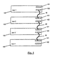
- FIG 1 illustrates in schematic and illustrative form a plurality of four devices 100 connected in a cascade.
- Each device comprises a "upstream” connection 101 and a “downstream” connection 102.
- the devices in the stack are connected by way of cables 50 which connected the downstream connection of one box with the upstream connection of the next box. (It is to be understood that the terms “upstream” and “downstream” are used simply to indicate the two directions in the stack Communication between the devices within the stack takes place in both directions.)
- Each cable 50 comprises a plurality of wires which connect to a plurality of pins within the connectors on each device in the stack.
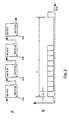
- FIG. 2 is a schematic diagram illustrating in more detail the connections formed within the devices within the stack and formed by the connecting cables 50.
- a subset 52 of the plurality of signals carried by cables 50 is provided to enable to devices in the stack to communicate with each other as desired to provide their normal functions.
- these signals 52 are simply transferred in parallel from the upstream connector of one device to the downstream connector of the subsequent device and are also connected in parallel between the upstream and downstream connectors within each device.
- This effectively provides a communication bus running up the stack and for the purposes of illustration core devices 110 are illustrated within each device 100 which communicate with each other via the communication bus. This communication may be by any method and is not fundamental to the basics of this invention, although a specific scheme will be discussed later.
- each connector on each box which are connected as shown via two wires 54 in cable 50. These connections enable the automatic determination of the positions within the stack by the different devices.
- means 120 for determining the current identification of each device in the stack and also devices 130 which are arranged to sense if the device is at the top or bottom of the stack.
- each device 120 As shown the signal output from each device 120 is connected to the input of the subsequent device 120. This enables each device 100 to generate its own identification based on the identification of the adjacent device in the stack which results in each device in the stack assigning to itself a unique identification code. This feature of the described arrangement is claimed in the parent case.
- Figure 3 illustrates the connections of the device 120.
- Each of these devices is configured such that when nothing is connected to its input, it provides at its output a pulse train in which the width of each pulse is w1 and time between pulses is T.
- This is illustrated in Figure 3B.
- each device receives the pulse train output by the preceding device and increases the width of the pulses in the pulse train by units of w1, without altering the period T.
- Each device determines it own identification by measuring the width of the pulses received on the input. Therefore in the configuration illustrated in Figure 3A, the first box 120 takes identification 0, the next takes the identification 1, the next takes the identification 2 and the final box takes identification 3.
- Another connection provided by cable 50 runs between units 130 in the devices in the stack. This is provided to enable the devices to detect if they are at the end of the stack.
- each unit 130 there are provided two complementary devices, each of which is capable of detecting whether it is connected to a complementary device in a succeeding device in the stack. If it is determined that both of the complementary devices are so connected then it is established that the device in question is not at the end of the stack. If only one of the complementary devices is so connected then it is established that the device in question is at the end of a stack.
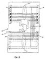
- Suitable circuitry for comprising devices 130 is illustrated in Figure 4
- FIG 4 there are shown in schematic form two units 130, each of which comprises two complementary devices 132, 136.
- Device 132 has terminal 133 which is connected to a terminal in one of the downstream or upstream connectors of the device 100.
- Device 136 has terminal 137 which is connected to a terminal in the other of the upstream or downstream connectors. Therefore, by way of one of connections 54, for each connection between devices 100 in a stack there is a connection between a terminal 133 and a terminal 137.
- a low signal on a terminal 134 or 138 indicates that a connection to a succeeding device has been made, while a high signal on terminal 134 or 138 indicates that no connection has been made.
- Devices 130 can therefore perform a simple logical operation on the outputs of terminals 134,138 to determine if termination of the communication bus is desired. In particular if both signals are low then no termination is required, while if one of the signals is high then termination is required.
- the input and output side of devices 130 may use the same number pin in each of the upstream and downstream connectors on each device in the stack
- the input and output signals use different pins in the upstream and downstream connections and this enables the upstream and downstream connectors to be made physically different, thereby, in conjunction with appropriately manufactured cables 50, ensuring that only correct connections can be made between devices in the stack.
- the determination of whether a device is at the end of the stack can be used to switch appropriate termination circuitry on to the communication bus 52 to prevent reflections at the end of the bus in a known fashion.
- each connecting device 60 comprises connectors 1a and 2a which connect respectively with the upstream and downstream connectors on a device in the stack.
- the connecting device 60 also comprises connectors 1b and 2b to which cables 50 can be connected.
- the connecting device also provides a parallel connection for at least signals 52 from connector 1b to connector 2b.
- signals 54 which run between devices 120 and 130 as will be discussed in detail below, but it will be appreciated that the parallel connection of signals 52 between connectors 1b and 2b means that even if a device is disconnected from connectors 1a and 2a, the communication between the remaining devices in the stack can continue via connectors 1b and 2b to which the cables 50 are attached.
- the connecting device 60 comprises means for receiving a signal 62 indicating if connectors 1a and 2a are attached to a device in the stack and, if they are not so connected, the signals running between devices 120 and 130 are simply bussed between connectors 1b and 2b in the same way as the communication signals. Therefore in this event it is as if the connector circuit 60 was not present and the remaining devices in the stack derive their identifications in the normal way as described above.
- the above described cascade arrangement is used for connecting a plurality of repeater devices in a local area network (LAN).
- Each device may comprise four repeaters connecting a plurality of ports to which users may attach.
- Each such device has five ports which it is desired to connect to the cascade connection.
- Each of these three wire links comprises one twisted pair which carries data and one extra wire for collision detection as in a normal ethernet connection.
- This efficient use of signals in the cascade connection means that the five communications channels plus the device identification signals according to this invention described above can all be accommodated in a single 25-way d-type connector. This is advantageous because such connectors are very standard in this field and are therefore available cheaply enabling the devices according to this embodiment of the invention to be manufactured at relatively low cost.
- one or both of the no fit pins the cascade-out connector and the cascade-in connector may be polarised to provide the unit present signal to the connecting device 60.
Description
- This application is divided from European Patent Application 97932943.0, the "parent case".
- The present invention relates to the cascade connection of a plurality of devices so as to enable them to communicate and function together.
- In, for example, computer networks comprising a number of users there are provided communication hubs which enable the users to communicate with each other. The communication hub would typically comprise a plurality of ports to which the users would be connected, and would also comprise means to enable the ports to communicate with each other, thereby allowing the different users to communicate. As is well known, the connections between the ports may be arranged in various ways, for instance the device may be what is known as a repeater, in which communications received on one port are simply output on all of the other ports, or the device may be what is known as a bridge, in which data received on any port is only output to that port for which it is destined, or it may be any other form of communications device. In such an arrangement, the capacity of the network, in terms of the number of users which may be connected, is limited by the number of ports provided on the communications device. If it is desired to increase the capacity of the network it would of course be possible to replace the communications device with another device having an increased number of ports. However, this is generally considered not to be a good solution both in terms of wastage (the original device becomes redundant) and also in terms of product supply (a manufacturer must have in its product range a potentially large number of differently sized products).
- A better approach to the problem is to provide communications devices which may themselves be connected together in what may be considered to be a "stack" such that when the capacity of existing equipment is exhausted further capacity may be added by simply adding an additional device to the stack. In such a stack it is necessary to provide interconnection between the stacked devices via what is known as a cascade connection, in order to allow users connected to one device to communicate with users connected to other devices.
- The present invention provides a network communication device comprising a plurality of ports whereby connection can be made to network equipment and connection means arranged to enable connection to two other similar devices whereby a plurality of said devices may be cascade connected, the device comprising sensing means arranged to sense whether the device is at the end of a series of cascade connected devices, said sensing means comprising:
- first and second complementary circuitry providing first and second outputs respectively and having first and second interconnections respectively, the first and second circuitry being arranged whereby said first output has a first value in the event that said first interconnection is connected to a second interconnection in another device and a second value if it is not so connected, and whereby said second output has a first value in the event that said second interconnection is connected to a first interconnection in another device and a second value if it not so connected; and
- means arranged to indicate that said device is at the end of a series of cascade connected devices when one of said first and second outputs takes it second value.
-
- The present invention facilitates the stacking of devices by a user and reduces the amount of manual setting up of the stack of devices which is required to be undertaken by a user.
- The automatic detection of the end of the stack means that the stack can be re-configured by addition or removal of devices and these alterations will automatically be taken into account by the stack as a whole.
- As mentioned above, in this invention each unit is able to detect whether it is at the top or the bottom of the stack, and in the preferred implementation of this aspect it is only necessary to provide two additional connections in the cascade connection between the devices to provide this function.
- In a preferred development of the invention the devices are also provided with suitable circuitry for terminating the communication bus which is effectively provided by the cascade connection of the devices, and this termination circuitry is switched on to the cascade connection if the device is at the end of the stack
- In one implementation of the invention the devices are connected in cascade by the provision of two connectors on each device and the devices are serially connected together by way of a plurality of cables between the first connector on one box and the second connector on the next box.
- In such an arrangement, the removal of a device in the middle of the stack causes the stack to be divided in two. In order to avoid the possible disadvantages of this, in a preferred embodiment, a further device is provided which is connected between the cables and each device which enables the removal of a communications device without breaking the cascade connection of the remaining devices.
- As mentioned above this invention is particularly applicable to data communication devices in computer networks and in a particular embodiment of this invention, due to the low number of extra connections which are required to perform the above-mentioned automatic functions of the cascade, it is possible to provide five independent communication links in the stack using only 25- way connectors for the cascade.
- This invention will be better understood from the following description of a preferred embodiment given by way of example and in conjunction with the accompanying drawings in which:-
- Figure 1 illustrates the cascade connection of four devices ;
- Figure 2 illustrates in more detail the arrangement of Figure 1 according to the preferred embodiment;
- Figure 3 illustrates the allocation of identification within a stack;
- Figure 4 illustrates the end-of-stack sensing devices; and
- Figure 5 illustrates the operation of a connecting device according to a particularly preferred embodiment.
-
- Figure 1 illustrates in schematic and illustrative form a plurality of four
devices 100 connected in a cascade. Each device comprises a "upstream"connection 101 and a "downstream"connection 102. The devices in the stack are connected by way ofcables 50 which connected the downstream connection of one box with the upstream connection of the next box. (It is to be understood that the terms "upstream" and "downstream" are used simply to indicate the two directions in the stack Communication between the devices within the stack takes place in both directions.) - Each
cable 50 comprises a plurality of wires which connect to a plurality of pins within the connectors on each device in the stack. - Figure 2 is a schematic diagram illustrating in more detail the connections formed within the devices within the stack and formed by the connecting
cables 50. As is illustrated, asubset 52 of the plurality of signals carried bycables 50 is provided to enable to devices in the stack to communicate with each other as desired to provide their normal functions. As shown, thesesignals 52 are simply transferred in parallel from the upstream connector of one device to the downstream connector of the subsequent device and are also connected in parallel between the upstream and downstream connectors within each device. This effectively provides a communication bus running up the stack and for the purposes ofillustration core devices 110 are illustrated within eachdevice 100 which communicate with each other via the communication bus. This communication may be by any method and is not fundamental to the basics of this invention, although a specific scheme will be discussed later. - There are additionally provided three pins on each connector on each box which are connected as shown via two
wires 54 incable 50. These connections enable the automatic determination of the positions within the stack by the different devices. Within each device there is providedmeans 120 for determining the current identification of each device in the stack and alsodevices 130 which are arranged to sense if the device is at the top or bottom of the stack. - As shown the signal output from each
device 120 is connected to the input of thesubsequent device 120. This enables eachdevice 100 to generate its own identification based on the identification of the adjacent device in the stack which results in each device in the stack assigning to itself a unique identification code. This feature of the described arrangement is claimed in the parent case. - One implementation of this is illustrated in Figure 3 which illustrates the connections of the
device 120. Each of these devices is configured such that when nothing is connected to its input, it provides at its output a pulse train in which the width of each pulse is w1 and time between pulses is T. This is illustrated in Figure 3B. Forsubsequent devices 120, each device receives the pulse train output by the preceding device and increases the width of the pulses in the pulse train by units of w1, without altering the period T. Each device determines it own identification by measuring the width of the pulses received on the input. Therefore in the configuration illustrated in Figure 3A, thefirst box 120 takes identification 0, the next takes theidentification 1, the next takes theidentification 2 and the final box takesidentification 3. - The generation of the pulse trains just mentioned takes place continually and therefore any alterations to the size or configuration of the stack are automatically accounted for. For instance, if a further device is added at the top of the stack this automatically takes the next identification available. If a extra device is added at the bottom of the stack, this automatically takes identification number 0, with the other devices renumbering themselves automatically. This configuration therefore ensures that, at any given time, each device in the stack has a unique identification which is indicative of its relative position within the stack.
- Another connection provided by
cable 50 runs betweenunits 130 in the devices in the stack. This is provided to enable the devices to detect if they are at the end of the stack. Within eachunit 130 there are provided two complementary devices, each of which is capable of detecting whether it is connected to a complementary device in a succeeding device in the stack. If it is determined that both of the complementary devices are so connected then it is established that the device in question is not at the end of the stack. If only one of the complementary devices is so connected then it is established that the device in question is at the end of a stack. Suitable circuitry for comprisingdevices 130 is illustrated in Figure 4 - In Figure 4 there are shown in schematic form two
units 130, each of which comprises twocomplementary devices Device 132 hasterminal 133 which is connected to a terminal in one of the downstream or upstream connectors of thedevice 100.Device 136 hasterminal 137 which is connected to a terminal in the other of the upstream or downstream connectors. Therefore, by way of one ofconnections 54, for each connection betweendevices 100 in a stack there is a connection between aterminal 133 and aterminal 137. - Considering
first device 132, when there is no connection toterminal 133, as illustrated in the left-hand side of Figure 4, no current flows through the resistors ofdevice 132 thereby causing a low signal to be applied to the inverting buffer, which in turn applies a high signal tooutput terminal 134. - In
device 136, when no connection is made toterminal 137 as illustrated in the right-hand side of Figure 4, the transistor is turned off causing no current to flow through the grounded resistor and settingterminal 138 to have a high value. - If a
device 132 is connected to adevice 136 as illustrated in the central portion of Figure 4 the interaction between the twodevices terminals - It will therefore be appreciated that a low signal on a terminal 134 or 138 indicates that a connection to a succeeding device has been made, while a high signal on
terminal Devices 130 can therefore perform a simple logical operation on the outputs of terminals 134,138 to determine if termination of the communication bus is desired. In particular if both signals are low then no termination is required, while if one of the signals is high then termination is required. - The input and output side of
devices 130 may use the same number pin in each of the upstream and downstream connectors on each device in the stack However, as illustrated in Figure 2 it is preferred that the input and output signals use different pins in the upstream and downstream connections and this enables the upstream and downstream connectors to be made physically different, thereby, in conjunction with appropriately manufacturedcables 50, ensuring that only correct connections can be made between devices in the stack. - As mentioned above the determination of whether a device is at the end of the stack can be used to switch appropriate termination circuitry on to the
communication bus 52 to prevent reflections at the end of the bus in a known fashion. - One additional problem which is a stack connected as illustrated in Figures 1 and 2 is that if an intermediate device is removed from the stack simply by unplugging the
cables 50 to which it is connected this will result in the remaining devices not being able to communicate with each other, because the stack is divided into two. - Therefore according to a further preferred feature of this invention there is additionally provided a connector for attachment between the devices in the stack and the
cables 50. This is illustrated in Figure 5 and is designatedpart 60. As illustrated each connectingdevice 60 comprisesconnectors device 60 also comprisesconnectors cables 50 can be connected. In addition to simply providing a parallel connection forsignals 52 betweenconnectors connectors device 60, the connecting device also provides a parallel connection for at least signals 52 fromconnector 1b toconnector 2b. The exceptions to this latter feature are thesignals 54 which run betweendevices signals 52 betweenconnectors connectors connectors cables 50 are attached. - The connecting
device 60 comprises means for receiving asignal 62 indicating ifconnectors devices connectors connector circuit 60 was not present and the remaining devices in the stack derive their identifications in the normal way as described above. - If however it is determined that
device 60 is connected to a device in the stack byconnectors signals 54 running betweendevices connectors circuit 60 thereby enabling the device to whichconnector 60 is attached to be accounted for in the identification scheme described above. - In a particularly preferred embodiment of this invention the above described cascade arrangement is used for connecting a plurality of repeater devices in a local area network (LAN). Each device may comprise four repeaters connecting a plurality of ports to which users may attach. Each such device has five ports which it is desired to connect to the cascade connection. There are therefore provided five ethernet standard communications busses within the bus provided by
cable 50, each one of these being provided by three wires. Each of these three wire links comprises one twisted pair which carries data and one extra wire for collision detection as in a normal ethernet connection. This efficient use of signals in the cascade connection means that the five communications channels plus the device identification signals according to this invention described above can all be accommodated in a single 25-way d-type connector. This is advantageous because such connectors are very standard in this field and are therefore available cheaply enabling the devices according to this embodiment of the invention to be manufactured at relatively low cost. - In a preferred configuration there are 11 twisted pairs in the cascade connection. As illustrated in Figure 2 there is one no fit pin on the cascade-in connector, and one no fit pin on the cascade-out connector. This leaves only one non-twisted pair connection (i.e. a single wire).
- In such an arrangement one or both of the no fit pins the cascade-out connector and the cascade-in connector may be polarised to provide the unit present signal to the connecting
device 60.
Claims (6)
- A network communication device comprising a plurality of ports whereby connection can be made to network equipment and connection means arranged to enable connection to two other similar devices whereby a plurality of said devices may be cascade connected, the device comprising sensing means (130) arranged to sense whether the device (100) is at the end of a series of cascade connected devices, said sensing means (130) comprising:first and second complementary circuitry (132,136) providing first and second outputs (134,138) respectively and having first and second interconnections (133,137) respectively, the first and second circuitry being arranged whereby said first output (134) has a first value in the event that said first interconnection (133) is connected to a second interconnection in another device and a second value if it is not so connected, and whereby said second output (138) has a first value in the event that said second interconnection (137) is connected to a first interconnection (133) in another device and a second value if it not so connected; andmeans arranged to indicate that said device is at the end of a series of cascade connected devices when one of said first and second outputs takes it second value.
- A network communication device according to claim 1 in which said first circuitry (132) comprises means arranged to drive said first interconnection (133) to a first logical level and the value of said first output (134) is dependent on whether current is drawn via first interconnection (133), and second circuity (136) comprises means arranged to pull said second interconnection (137) to a second logical level and to sense when said second interconnection is driven to said first logical level.
- A network communication device according to claim 1 further comprising a data bus termination device which is activated when it is determined that the device is at the end of a series of cascade connected devices.
- A communications apparatus comprising a plurality of network communication devices (100) each being a device according to any preceding claim, the devices being interconnected via cable segments (50) attached to said connection means (101,102) whereby to form a data bus.
- Apparatus according to claim 4 further comprising a cascade connection device (60) connected between said connection means (101,102) of at least one of said network communication devices (100) and the respective cable segments (50) to enable the removal of that communication device (100) without breaking the cascade connection of the remaining units.
- Apparatus according to claim 5 in which said cable segments (50) include a conductor to carry said pulses between said outputs and inputs of the network communication devices and the cascade connection device (60) comprises switch means responsive to whether or not the cascade connection device (60) is attached to a network communication device (10) to connect said conductors in the cable segments to the input and output of a said network communication device (10) if present or to connect said conductors in the cable segments together if no said network communication device is present.
Applications Claiming Priority (3)
| Application Number | Priority Date | Filing Date | Title |
|---|---|---|---|
| GB9615445 | 1996-07-23 | ||
| GBGB9615445.5A GB9615445D0 (en) | 1996-07-23 | 1996-07-23 | Cascade connection of communicating devices |
| EP97932943A EP0912944B1 (en) | 1996-07-23 | 1997-07-23 | Cascade connection of communicating devices |
Related Parent Applications (1)
| Application Number | Title | Priority Date | Filing Date |
|---|---|---|---|
| EP97932943A Division EP0912944B1 (en) | 1996-07-23 | 1997-07-23 | Cascade connection of communicating devices |
Publications (3)
| Publication Number | Publication Date |
|---|---|
| EP1008943A2 EP1008943A2 (en) | 2000-06-14 |
| EP1008943A3 EP1008943A3 (en) | 2001-10-31 |
| EP1008943B1 true EP1008943B1 (en) | 2003-04-02 |
Family
ID=10797365
Family Applications (2)
| Application Number | Title | Priority Date | Filing Date |
|---|---|---|---|
| EP00102428A Expired - Lifetime EP1008943B1 (en) | 1996-07-23 | 1997-07-23 | Cascade connection of communicating devices |
| EP97932943A Expired - Lifetime EP0912944B1 (en) | 1996-07-23 | 1997-07-23 | Cascade connection of communicating devices |
Family Applications After (1)
| Application Number | Title | Priority Date | Filing Date |
|---|---|---|---|
| EP97932943A Expired - Lifetime EP0912944B1 (en) | 1996-07-23 | 1997-07-23 | Cascade connection of communicating devices |
Country Status (6)
| Country | Link |
|---|---|
| US (1) | US6523070B1 (en) |
| EP (2) | EP1008943B1 (en) |
| JP (1) | JP2001518244A (en) |
| DE (2) | DE69720546T2 (en) |
| GB (2) | GB9615445D0 (en) |
| WO (1) | WO1998003921A1 (en) |
Families Citing this family (32)
| Publication number | Priority date | Publication date | Assignee | Title |
|---|---|---|---|---|
| GB9615445D0 (en) * | 1996-07-23 | 1996-09-04 | 3Com Ireland | Cascade connection of communicating devices |
| ES2156766B1 (en) * | 1999-11-16 | 2001-11-16 | Iglesias Angel Sa | SELF-DIRECTION SYSTEM FOR BUS CONNECTED DEVICES. |
| US7451242B2 (en) * | 2001-08-27 | 2008-11-11 | Xerox Corporation | Systems and methods for providing network access |
| US20030070027A1 (en) * | 2001-10-09 | 2003-04-10 | Yiu-Keung Ng | System for interconnecting peripheral host computer and data storage equipment having signal repeater means |
| GB2383508B (en) | 2001-12-22 | 2004-01-28 | 3Com Corp | Cascade control system for network units |
| GB2383927B (en) | 2001-12-22 | 2004-01-28 | 3Com Corp | Network unit and packets for use in a cascade system |
| US7376734B2 (en) * | 2002-02-14 | 2008-05-20 | Panduit Corp. | VOIP telephone location system |
| US7519000B2 (en) * | 2002-01-30 | 2009-04-14 | Panduit Corp. | Systems and methods for managing a network |
| US7451224B1 (en) | 2003-04-23 | 2008-11-11 | Cisco Technology, Inc. | Method and apparatus for automatically synchronizing a unique identifier of a network device |
| US7631055B1 (en) | 2003-04-23 | 2009-12-08 | Cisco Technology, Inc. | Method and apparatus providing automatic connection announcement from a modular network device to a network management point |
| US7876703B2 (en) * | 2003-06-13 | 2011-01-25 | International Business Machines Corporation | System and method for enabling connection among devices in a network |
| US20050141431A1 (en) | 2003-08-06 | 2005-06-30 | Caveney Jack E. | Network managed device installation and provisioning technique |
| CN1871861A (en) * | 2003-10-23 | 2006-11-29 | 泛达公司 | System to guide and monitor the installation and revision of network cabling of an active jack network |
| US7207846B2 (en) * | 2003-11-24 | 2007-04-24 | Panduit Corp. | Patch panel with a motherboard for connecting communication jacks |
| JP2005165589A (en) * | 2003-12-02 | 2005-06-23 | Fujitsu Ltd | Usb device recognition method and system |
| US7523185B1 (en) | 2004-01-13 | 2009-04-21 | Cisco Technology, Inc. | Method and apparatus for providing automatic frame relay and ATM provisioning of network devices |
| US7290164B1 (en) | 2004-03-03 | 2007-10-30 | Cisco Technology, Inc. | Method of reverting to a recovery configuration in response to device faults |
| CN101099397B (en) * | 2004-05-03 | 2012-02-08 | 泛达公司 | Powered patch panel |
| US20060047800A1 (en) * | 2004-08-24 | 2006-03-02 | Panduit Corporation | Systems and methods for network management |
| US8199754B2 (en) * | 2006-05-30 | 2012-06-12 | Hewlett-Packard Development Company, L. P. | Intrusion prevention system edge controller |
| US7613124B2 (en) * | 2005-05-19 | 2009-11-03 | Panduit Corp. | Method and apparatus for documenting network paths |
| US7978845B2 (en) * | 2005-09-28 | 2011-07-12 | Panduit Corp. | Powered patch panel |
| US7717932B2 (en) * | 2005-10-27 | 2010-05-18 | Medtronic Xomed, Inc. | Instrument and system for surgical cutting and evoked potential monitoring |
| US8016846B2 (en) | 2005-10-27 | 2011-09-13 | Medtronic Xomed, Inc. | Micro-resecting and evoked potential monitoring system and method |
| US8945164B2 (en) | 2005-10-27 | 2015-02-03 | Medtronic Xomed, Inc. | Guard device for surgical cutting and evoked potential monitoring system |
| US7817036B2 (en) * | 2007-04-30 | 2010-10-19 | International Business Machines Corporation | Cabled and cableless interface method for connecting units within a rack |
| US8130527B2 (en) * | 2008-09-11 | 2012-03-06 | Micron Technology, Inc. | Stacked device identification assignment |
| EP2687815A1 (en) | 2012-07-20 | 2014-01-22 | Hexagon Technology Center GmbH | Measurement machine communication |
| US10218672B2 (en) | 2012-09-05 | 2019-02-26 | Hexagon Technology Center Gmbh | Measuring machine communication with automatic address allocation |
| JP6358814B2 (en) * | 2014-02-27 | 2018-07-18 | 株式会社クボタ | Termination resistance management system |
| EP3113430B1 (en) * | 2014-02-27 | 2021-06-16 | Kubota Corporation | Electronic device, work machine, and management system for termination resistances |
| JP6358813B2 (en) * | 2014-02-27 | 2018-07-18 | 株式会社クボタ | Working machine electronic equipment and working machine |
Family Cites Families (8)
| Publication number | Priority date | Publication date | Assignee | Title |
|---|---|---|---|---|
| US4660141A (en) * | 1983-12-06 | 1987-04-21 | Tri Sigma Corporation | Self configuring computer network with automatic bus exchange of module identification numbers and processor assigned module numbers |
| EP0266016A2 (en) * | 1986-10-28 | 1988-05-04 | Eip Microwave Incorporated | Automatic circuit board configuration |
| GB2249460B (en) * | 1990-09-19 | 1994-06-29 | Intel Corp | Network providing common access to dissimilar hardware interfaces |
| US5120909A (en) * | 1991-04-26 | 1992-06-09 | Ag Communication Systems Corporation | Terminating devices detection and verification circuit |
| AU3464693A (en) * | 1992-02-07 | 1993-09-03 | HER MAJESTY THE QUEEN IN RIGHT OF THE GOVERNMENT OF NEW ZEALAND, acting by and through THE CHIEF OF DEFENCE FORCE | Communication method and apparatus |
| AU5350694A (en) * | 1992-10-02 | 1994-04-26 | Compaq Computer Corporation | Automatic disabling of termination of a digital computer bus |
| US5812796A (en) * | 1995-08-18 | 1998-09-22 | General Magic, Inc. | Support structures for an intelligent low power serial bus |
| GB9615445D0 (en) * | 1996-07-23 | 1996-09-04 | 3Com Ireland | Cascade connection of communicating devices |
-
1996
- 1996-07-23 GB GBGB9615445.5A patent/GB9615445D0/en active Pending
-
1997
- 1997-07-23 DE DE69720546T patent/DE69720546T2/en not_active Expired - Lifetime
- 1997-07-23 GB GB9900809A patent/GB2331435A/en not_active Withdrawn
- 1997-07-23 WO PCT/GB1997/001995 patent/WO1998003921A1/en active IP Right Grant
- 1997-07-23 EP EP00102428A patent/EP1008943B1/en not_active Expired - Lifetime
- 1997-07-23 DE DE69703584T patent/DE69703584T2/en not_active Expired - Lifetime
- 1997-07-23 EP EP97932943A patent/EP0912944B1/en not_active Expired - Lifetime
- 1997-07-23 US US09/230,391 patent/US6523070B1/en not_active Expired - Fee Related
- 1997-07-23 JP JP50671498A patent/JP2001518244A/en not_active Ceased
Also Published As
| Publication number | Publication date |
|---|---|
| EP1008943A2 (en) | 2000-06-14 |
| WO1998003921A1 (en) | 1998-01-29 |
| US6523070B1 (en) | 2003-02-18 |
| DE69720546T2 (en) | 2004-09-16 |
| GB2331435A (en) | 1999-05-19 |
| DE69720546D1 (en) | 2003-05-08 |
| DE69703584D1 (en) | 2000-12-28 |
| GB9615445D0 (en) | 1996-09-04 |
| EP1008943A3 (en) | 2001-10-31 |
| EP0912944A1 (en) | 1999-05-06 |
| DE69703584T2 (en) | 2001-06-21 |
| JP2001518244A (en) | 2001-10-09 |
| EP0912944B1 (en) | 2000-11-22 |
Similar Documents
| Publication | Publication Date | Title |
|---|---|---|
| EP1008943B1 (en) | Cascade connection of communicating devices | |
| JP2510080B2 (en) | System device and method for connecting multiple protocol terminals | |
| US5357518A (en) | Network interface | |
| EP0226765B1 (en) | Variable length backplane bus | |
| EP0843260B1 (en) | Automatic shelf-address assignment for shelves containing disk drives and error detection method and apparatus | |
| US8939798B2 (en) | Local area networks for intelligent patching system controllers and related methods, controllers and communications interfaces | |
| EP0981227A2 (en) | Power feeding system for telephone terminal in LAN | |
| US5864715A (en) | System for automatically terminating a daisy-chain peripheral bus with either single-ended or differential termination network depending on peripheral bus signals and peripheral device interfaces | |
| JPH07262128A (en) | Method and apparatus for constitution of functional unit in serial master/ slave apparatus | |
| PL179711B1 (en) | Multiple-port lan selector switch for token-ring networks | |
| US5680113A (en) | Dynamic address assignments to serially connected devices | |
| EP0947076A1 (en) | Network including multi-protocol cross-connect switch | |
| EP1262783B1 (en) | An apparatus, a method for testing an electrical wiring system, a computer program for testing an electrical wiring system | |
| WO1998028883B1 (en) | Network including multi-protocol cross-connect switch | |
| US5531611A (en) | Connector module for local area network | |
| EP0837581A2 (en) | Hot-swappable interconnections for stackable network hubs | |
| JPH0646074A (en) | Signal distributing device having automatic terminating function | |
| US6493393B1 (en) | Digital communication bus for connecting electronic modules | |
| JPH1195883A (en) | Communication control unit and interface cable | |
| KR100439223B1 (en) | UART interface device | |
| WO1998048487A1 (en) | Cable system | |
| JP3000689B2 (en) | Network concentrator and network configuration method using the same | |
| JP2854770B2 (en) | Outlet with status display function | |
| AU7014898A (en) | Cable system | |
| JPH0993255A (en) | Outlet for information wiring |
Legal Events
| Date | Code | Title | Description |
|---|---|---|---|
| PUAI | Public reference made under article 153(3) epc to a published international application that has entered the european phase |
Free format text: ORIGINAL CODE: 0009012 |
|
| AC | Divisional application: reference to earlier application |
Ref document number: 912944 Country of ref document: EP |
|
| AK | Designated contracting states |
Kind code of ref document: A2 Designated state(s): CH DE ES FI FR GB LI NL |
|
| AX | Request for extension of the european patent |
Free format text: AL;LT;LV;RO;SI |
|
| RAP1 | Party data changed (applicant data changed or rights of an application transferred) |
Owner name: 3COM TECHNOLOGIES |
|
| PUAL | Search report despatched |
Free format text: ORIGINAL CODE: 0009013 |
|
| AK | Designated contracting states |
Kind code of ref document: A3 Designated state(s): CH DE ES FI FR GB LI NL |
|
| AX | Request for extension of the european patent |
Free format text: AL;LT;LV;RO;SI |
|
| 17P | Request for examination filed |
Effective date: 20011116 |
|
| GRAG | Despatch of communication of intention to grant |
Free format text: ORIGINAL CODE: EPIDOS AGRA |
|
| 17Q | First examination report despatched |
Effective date: 20020514 |
|
| AKX | Designation fees paid |
Free format text: CH DE ES FI FR GB LI NL |
|
| GRAG | Despatch of communication of intention to grant |
Free format text: ORIGINAL CODE: EPIDOS AGRA |
|
| GRAH | Despatch of communication of intention to grant a patent |
Free format text: ORIGINAL CODE: EPIDOS IGRA |
|
| GRAH | Despatch of communication of intention to grant a patent |
Free format text: ORIGINAL CODE: EPIDOS IGRA |
|
| GRAA | (expected) grant |
Free format text: ORIGINAL CODE: 0009210 |
|
| RBV | Designated contracting states (corrected) |
Designated state(s): DE GB |
|
| AC | Divisional application: reference to earlier application |
Ref document number: 0912944 Country of ref document: EP Kind code of ref document: P |
|
| AK | Designated contracting states |
Designated state(s): DE GB |
|
| REG | Reference to a national code |
Ref country code: GB Ref legal event code: FG4D |
|
| REF | Corresponds to: |
Ref document number: 69720546 Country of ref document: DE Date of ref document: 20030508 Kind code of ref document: P |
|
| PLBE | No opposition filed within time limit |
Free format text: ORIGINAL CODE: 0009261 |
|
| STAA | Information on the status of an ep patent application or granted ep patent |
Free format text: STATUS: NO OPPOSITION FILED WITHIN TIME LIMIT |
|
| 26N | No opposition filed |
Effective date: 20040105 |
|
| PGFP | Annual fee paid to national office [announced via postgrant information from national office to epo] |
Ref country code: GB Payment date: 20130626 Year of fee payment: 17 |
|
| REG | Reference to a national code |
Ref country code: DE Ref legal event code: R082 Ref document number: 69720546 Country of ref document: DE Representative=s name: CORINNA VOSSIUS IP GROUP PATENT- UND RECHTSANW, DE |
|
| REG | Reference to a national code |
Ref country code: DE Ref legal event code: R082 Ref document number: 69720546 Country of ref document: DE Representative=s name: CORINNA VOSSIUS IP GROUP PATENT- UND RECHTSANW, DE |
|
| PGFP | Annual fee paid to national office [announced via postgrant information from national office to epo] |
Ref country code: DE Payment date: 20130621 Year of fee payment: 17 |
|
| REG | Reference to a national code |
Ref country code: DE Ref legal event code: R119 Ref document number: 69720546 Country of ref document: DE |
|
| GBPC | Gb: european patent ceased through non-payment of renewal fee |
Effective date: 20140723 |
|
| PG25 | Lapsed in a contracting state [announced via postgrant information from national office to epo] |
Ref country code: DE Free format text: LAPSE BECAUSE OF NON-PAYMENT OF DUE FEES Effective date: 20150203 |
|
| REG | Reference to a national code |
Ref country code: DE Ref legal event code: R119 Ref document number: 69720546 Country of ref document: DE Effective date: 20150203 |
|
| PG25 | Lapsed in a contracting state [announced via postgrant information from national office to epo] |
Ref country code: GB Free format text: LAPSE BECAUSE OF NON-PAYMENT OF DUE FEES Effective date: 20140723 |