EP1010179B1 - Two step memory device command buffer apparatus and method and memory devices and computer systems using same - Google Patents
Two step memory device command buffer apparatus and method and memory devices and computer systems using same Download PDFInfo
- Publication number
- EP1010179B1 EP1010179B1 EP98930199A EP98930199A EP1010179B1 EP 1010179 B1 EP1010179 B1 EP 1010179B1 EP 98930199 A EP98930199 A EP 98930199A EP 98930199 A EP98930199 A EP 98930199A EP 1010179 B1 EP1010179 B1 EP 1010179B1
- Authority
- EP
- European Patent Office
- Prior art keywords
- command
- word
- storage
- words
- bit
- Prior art date
- Legal status (The legal status is an assumption and is not a legal conclusion. Google has not performed a legal analysis and makes no representation as to the accuracy of the status listed.)
- Expired - Lifetime
Links
Images


Classifications
-
- G—PHYSICS
- G11—INFORMATION STORAGE
- G11C—STATIC STORES
- G11C7/00—Arrangements for writing information into, or reading information out from, a digital store
-
- G—PHYSICS
- G11—INFORMATION STORAGE
- G11C—STATIC STORES
- G11C7/00—Arrangements for writing information into, or reading information out from, a digital store
- G11C7/10—Input/output [I/O] data interface arrangements, e.g. I/O data control circuits, I/O data buffers
- G11C7/1072—Input/output [I/O] data interface arrangements, e.g. I/O data control circuits, I/O data buffers for memories with random access ports synchronised on clock signal pulse trains, e.g. synchronous memories, self timed memories
Landscapes
- Dram (AREA)
- Memory System Of A Hierarchy Structure (AREA)
- Communication Control (AREA)
Abstract
Description
Claims (34)
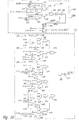
- A command buffer for a memory device adapted to receive a command packet of N M-bit command words on an M-bit bus, the command buffer comprising:M shift registers (202) each having an input terminal, an output terminal, and a clock terminal, the input terminal of each of the shift registers (202) being coupled to a respective bit of the M-bit bus; anda control circuit (205) having a clock terminal and at least one output terminal; the command buffer being characterised in that:each of the shift registers (202) having N/Y stages (252) with a respective command word bit applied to the input terminal of each stage (252) being shifted to an output terminal of each stage (252) responsive to a clock signal adapted to be applied to the clock terminals of the shift registers (202);the command buffer further including Y storage registers (206, 208), where Y is an integer number greater than 1, each of the storage registers (206, 208) having (N/Y)*M storage cells, each of the storage cells having an output terminal, an input terminal coupled to the output terminal of a respective shift register stage, and a load terminal, each of the storage cells storing a signal at the output terminal of the respective shift register stage responsive to a load signal applied to the load terminal of the storage cell; and further characterised in thatthe control circuit (205) generating the load signals after each N/Y of the command words having been shifted into the shift registers (202), the load signals being sequentially applied to the load terminals of successive storage registers (206, 208) so that the storage registers (206, 208) each receive respective N/Y command words as N command words are shifted into the shift registers (202).
- The command buffer of Claim 1, wherein N is equal to 4 and Y is equal to 2 so that the shift registers (202) each have two stages (252), and there are two storage registers (206, 208) each of which has 2*M storage cells.
- The command buffer of Claim 1 or 2, further comprising a command decoder (216) coupled to one of the storage registers (206, 208) that stores command words received from the shift registers (202) before command words are stored in another shift register, the decoder (216) decoding the command words stored in the storage register (206, 208) before command words have been stored in the other storage register.
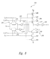
- The command buffer of any preceding claim, further comprising a comparison circuit coupled to a first of the storage registers (206, 208) that stores command words received from the shift registers (202) before command words are stored in a second shift register, the comparison circuit determining if at least a portion of the command word stored in the first storage register (206, 208) has a specific value and generating a select signal (CHPSEL) in response thereto, the comparison circuit comprising:a latch (212) storing the specific command word value and outputting a comparison word corresponding thereto; anda comparator (214) having a first input coupled to the first storage register (206, 208) and a second input coupled to the latch (212), the comparator (214) comparing the comparison word with at least a portion of the command word stored in the first storage register (206, 208) and generating the select signal (CHPSEL) responsive to a match between the comparison word and the portion of the command word.
- The command buffer of Claim 4, wherein the comparator (214) compares the comparison word with the portion of the command word before N/Y command words are stored in the second shift register.
- The command buffer of Claim 4 or 5, wherein the comparator (214) comprises:an exclusive OR gate (390) for each compared bit of the command word, each exclusive OR gate (390) having a pair of input terminals receiving a bit of the comparison word and a corresponding bit of the command word, the exclusive OR gates (390) collectively generating the select signal (CHPSEL) responsive to a match between all of the compared bits of the comparison word and the bits of the command word.
- The command buffer of Claim 1, further comprising an enable circuit for generating a select signal that enables functions on an integrated circuit containing the command buffer, the enable circuit comprising:a first decoder circuit (210) having an input bus coupled to one of the storage registers (206, 208), the first decoder (210) generating a load signal (LOADID) at an output terminal responsive to at least a portion of the command word having a predetermined value;an ID register (212) having an input bus coupled to the respective output terminals of one of the storage registers (206, 208), the ID register (212) storing at least a portion of a command word received from the storage register (206, 208) responsive to the load signal (LOADID) and generating on an output bus a comparison word corresponding thereto; anda comparator (214) having a first input bus coupled to a first of the storage registers (206, 208) that stores command words received from the shift registers (202) before command words are stored in a second shift register, the comparator (214) further having a second input bus coupled to the output bus of the ID register (212).
- The command buffer of Claim 7, wherein the comparator (214) compares the comparison word with at least a portion of the command word received from the first storage register (206, 208) and generates the select signal (CHPSEL) responsive to a match between the comparison word and the portion of the command word.
- The command buffer of Claim 7 or 8, wherein the comparator (214) comprises:an exclusive OR gate (390) for each compared bit of the command word received from the first storage register (206, 208), each exclusive OR gate (390) having a pair of input terminals receiving a bit of the comparison word and a corresponding bit of the command word, the exclusive OR gates (390) collectively generating the select signal (CHPSEL) responsive to a match between all of the compared bits of the comparison word and the bits of the command word.
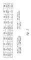
- The command buffer of any preceding claim, wherein each of the shift register stages (252) comprise;a transfer gate (260) having an input terminal adapted to receive one of the M-bits of the command word and transfer the command bit to an output terminal responsive to at least one first predetermined portion of the clock signal;a first storage device (262) coupled to the output terminal of the transfer gate (260), the first storage device (262) storing the command word bit from the output terminal of the transfer gate (260) and applying the stored command word bit to an output terminal of the first storage device (262);a second transfer gate (264) having an input terminal adapted to receive the stored command word bit from the output terminal of the first storage device (262) and transfer the command bit to an output terminal responsive to at least one second predetermined portion of the clock signal; anda second storage device (266) coupled to the output terminal of the second transfer gate (264), the second storage device (266) storing the command word bit from the output terminal of the second transfer gate (264) and applying the stored command word bit to an output terminal of the second storage device (266).
- The command buffer of Claim 10, wherein the second transfer gate (264) comprises first, second, third, and fourth switches connected in series with each other between first and second reference voltages, each of the switches having a control terminal, the control terminals of the second and third switches being coupled the output terminal of the first storage device (206, 208) to receive the stored command word bit from the first storage device (206, 208), the second switch closing responsive to a command word bit of one value and the third switch closing responsive to a command word bit of another value, a node between the second and third switches being coupled to the second storage device, the control terminals of the first and fourth switches being coupled to the clock signal to close the first and second switches responsive to at least one second predetermined portion of the clock signal.
- The command buffer of any preceding claim, wherein the control circuit (205) comprises a shift register (246, 248) having a start terminal adapted to receive a start signal (FLAG), the shift register (246, 248) having N stages with the start signal (FLAG) applied to an input terminal of the first stage being shifted from one stage to the next responsive to clock signals, the load signals being generated responsive to the start signal (FLAG) being shifted to the output of respective stages of the shift register (246, 248).
- The command buffer of Claim 12, wherein the control circuit (205) further comprises a clock sync circuit (230) synchronizing the start signal (FLAG) to the clock signal, the clock sync circuit (230) comprising a logic circuit receiving the clock signal and the output of one of the shift register stages, the logic circuit generating the load signals on a predetermined edge of the clock signal after the start signal (FLAG) has been shifted out of a respective shift register stage (252).
- The command buffer of any preceding claim, wherein the command word bits applied to the input terminal of respective shift registers (202) is shifted through two stages of the shift register (202) for each cycle of the clock signal.
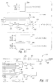
- A memory device, comprising:at least one array of memory cells adapted to store data at a location determined by a row address and a column address responsive to a command word;a row address circuit adapted to receive and decode the row address, and select a row of memory cells corresponding to the row address responsive to the command word;a column address circuit adapted to receive or apply data to one of the memory cells in the selected row corresponding to the column address responsive to the command word;a data path circuit adapted to couple data between an external terminal and the column address circuit responsive to the command word; anda command buffer according to any preceding claim.
- The memory device of Claim 15, wherein N is equal to 8 and Y is equal to 2 so that the shift registers (202) each have four stages, and there are two storage registers (206, 208) each of which has 4*M storage cells.
- The memory device of Claim 15 or 16, wherein the memory device comprises a random access memory.
- The memory device of Claim 15 or 16, wherein the memory device comprises a dynamic random access memory.
- The memory device of Claim 15 or 16, wherein the memory device comprises a packetized dynamic random access memory.
- A computer system, comprising:a processor having a processor bus;an input device coupled to the processor through the processor bus and adapted to allow data to be entered into the computer system;an output device coupled to the processor through the processor bus adapted to allow data to be output from the computer system; anda memory device according to any one of Claims 15 to 19, coupled to the processor through the processor bus.
- A method of processing a command packet of N M-bit command words for use by a memory device, the method characterised in that the method comprises:sequentially storing command words until N/Y command words have been stored;each time N/Y command words have been stored, transferring the [N/Y]*M bits of the command words to one of Y respective storage locations (206, 208); andoutputting the command words from each of the Y storage locations (206, 208).
- The method of Claim 21, wherein the step of outputting the command words from each of the Y storage locations (206, 208) comprises outputting the command words from at least one of the storage locations (206, 208) before command words have been transferred to another of the storage locations (206, 208).
- The method of Claim 22, further comprising processing at least part of the command word transferred to the one storage location (206, 208) before command words have been transferred to the other storage location (206, 208).
- The method of any one of Claims 21 to 23, wherein N is equal to 4 and Y is equal to 2 so that 2 commands words are. stored before being transferred to one of 2 storage locations (206, 208).
- The method of any one of Claims 21 to 24, further comprising the steps of:providing an identification word; andcomparing at least a portion of a command word with the identification word, and, in the event of a match, performing an operation in the memory device that corresponds to another portion of a command word.
- The method of Claim 25, wherein the step of comparing the portion of a command word with the identification word comprises comparing a portion of a command word that is transferred to one of the storage locations (206, 208) before the command word to which the operation corresponds is transferred to another of the storage locations (206, 208).
- The method of Claim 25 or 26, wherein the step of providing the identification word comprises:determining if at least a portion of the command word has a second predetermined value; andif at least a portion of the command word has a second predetermined value, storing at least a portion of a command word as the identification word.
- A method of processing a command packet of N M-bit command words in a computer system having a processor having a processor bus coupled to an input device, an output device, and a plurality of packetized memory devices, characterised in that the method comprises:sequentially storing command words in a plurality of the memory devices until N/Y command words have been stored;each time N/Y command words have been stored, transferring the [N/Y]*M bits of the command words to one of Y respective storage locations (206, 208);outputting the command words from each of the Y storage locations (206, 208).providing respective identification words unique to each of the memory devices;comparing at least a portion of a command word output from one of the storage locations (206, 208) in a plurality of the memory devices with the respective identification words for the memory devices; andin the event of a match between the portion of a command word and an identification word in a memory device, performing an operation corresponding to a command word in the memory device having an identification word matching the portion of the command word.
- The method of Claim 28, wherein the step of providing each of the identification words comprises:determining if at least a portion of the command word has a second predetermined value; andif at least a portion of the command word has a second predetermined value, storing at least a portion of the command word as the identification word.
- The method of Claim 28 or 29, wherein the step of comparing the portion of a command word with the respective identification word comprises comparing a portion of a command word from at least one of the storage locations (206, 208) before command words have been transferred to another of the storage locations (206, 208).
- The method device of Claim 28, wherein N is equal to 8 and Y is equal to 2 so that four command words are stored before being transferred to on of the 2 storage locations (206, 208).
- A method of processing a multi-command word command packet applied to a memory device, comprising:sequentially storing command words in the memory device as the command words are applied to the memory device; and characterised in thatthe method includes processing at least a portion of at least one of the command words of a command packet that is stored in the memory device prior to storing other command words of the command packet that are subsequently applied to the memory device.
- The method of Claim 32, wherein the step of processing at least a portion of at least one of the command words comprises decoding the portion of the command word.
- The method of Claim 32, wherein the step of processing at least a portion of at least one of the command words comprises comparing the portion of the command word to a comparison word, and, in the event of a match, enabling the memory device to respond to other command words in the command packet.
Applications Claiming Priority (3)
| Application Number | Priority Date | Filing Date | Title |
|---|---|---|---|
| US08/874,690 US5996043A (en) | 1997-06-13 | 1997-06-13 | Two step memory device command buffer apparatus and method and memory devices and computer systems using same |
| US874690 | 1997-06-13 | ||
| PCT/US1998/012335 WO1998057331A1 (en) | 1997-06-13 | 1998-06-12 | Two step memory device command buffer apparatus and method and memory devices and computer systems using same |
Publications (2)
| Publication Number | Publication Date |
|---|---|
| EP1010179A1 EP1010179A1 (en) | 2000-06-21 |
| EP1010179B1 true EP1010179B1 (en) | 2002-03-06 |
Family
ID=25364346
Family Applications (1)
| Application Number | Title | Priority Date | Filing Date |
|---|---|---|---|
| EP98930199A Expired - Lifetime EP1010179B1 (en) | 1997-06-13 | 1998-06-12 | Two step memory device command buffer apparatus and method and memory devices and computer systems using same |
Country Status (8)
| Country | Link |
|---|---|
| US (3) | US5996043A (en) |
| EP (1) | EP1010179B1 (en) |
| JP (1) | JP3869021B2 (en) |
| KR (1) | KR100434211B1 (en) |
| AT (1) | ATE214193T1 (en) |
| AU (1) | AU7965098A (en) |
| DE (1) | DE69804108T2 (en) |
| WO (1) | WO1998057331A1 (en) |
Families Citing this family (37)
| Publication number | Priority date | Publication date | Assignee | Title |
|---|---|---|---|---|
| US6230245B1 (en) | 1997-02-11 | 2001-05-08 | Micron Technology, Inc. | Method and apparatus for generating a variable sequence of memory device command signals |
| US6175894B1 (en) | 1997-03-05 | 2001-01-16 | Micron Technology, Inc. | Memory device command buffer apparatus and method and memory devices and computer systems using same |
| US5996043A (en) | 1997-06-13 | 1999-11-30 | Micron Technology, Inc. | Two step memory device command buffer apparatus and method and memory devices and computer systems using same |
| US6484244B1 (en) | 1997-06-17 | 2002-11-19 | Micron Technology, Inc. | Method and system for storing and processing multiple memory commands |
| US6202119B1 (en) | 1997-12-19 | 2001-03-13 | Micron Technology, Inc. | Method and system for processing pipelined memory commands |
| US6175905B1 (en) | 1998-07-30 | 2001-01-16 | Micron Technology, Inc. | Method and system for bypassing pipelines in a pipelined memory command generator |
| US6178488B1 (en) | 1998-08-27 | 2001-01-23 | Micron Technology, Inc. | Method and apparatus for processing pipelined memory commands |
| US6088293A (en) * | 1998-09-08 | 2000-07-11 | Texas Instruments Incorporated | Low-power column decode circuit |
| JP3765931B2 (en) * | 1998-10-15 | 2006-04-12 | 富士通株式会社 | Buffer control method and buffer control apparatus |
| US6646953B1 (en) | 2000-07-06 | 2003-11-11 | Rambus Inc. | Single-clock, strobeless signaling system |
| US6321282B1 (en) | 1999-10-19 | 2001-11-20 | Rambus Inc. | Apparatus and method for topography dependent signaling |
| US6643787B1 (en) * | 1999-10-19 | 2003-11-04 | Rambus Inc. | Bus system optimization |
| US7051130B1 (en) | 1999-10-19 | 2006-05-23 | Rambus Inc. | Integrated circuit device that stores a value representative of a drive strength setting |
| US7079775B2 (en) | 2001-02-05 | 2006-07-18 | Finisar Corporation | Integrated memory mapped controller circuit for fiber optics transceiver |
| US7151778B2 (en) * | 2001-04-18 | 2006-12-19 | Brocade Communications Systems, Inc. | Frame filtering of fibre channel packets |
| US7366194B2 (en) | 2001-04-18 | 2008-04-29 | Brocade Communications Systems, Inc. | Fibre channel zoning by logical unit number in hardware |
| US7549011B2 (en) * | 2001-08-30 | 2009-06-16 | Micron Technology, Inc. | Bit inversion in memory devices |
| US6775759B2 (en) * | 2001-12-07 | 2004-08-10 | Micron Technology, Inc. | Sequential nibble burst ordering for data |
| GB2400282B8 (en) * | 2003-03-31 | 2014-08-27 | St Microelectronics Res & Dev | Integrated circuit for code acquisition |
| US20040194500A1 (en) * | 2003-04-03 | 2004-10-07 | Broadway Entertainment, Inc. | Article of jewelry |
| US6928027B2 (en) * | 2003-04-11 | 2005-08-09 | Qualcomm Inc | Virtual dual-port synchronous RAM architecture |
| US7352740B2 (en) * | 2003-04-29 | 2008-04-01 | Brocade Communciations Systems, Inc. | Extent-based fibre channel zoning in hardware |
| US7707330B2 (en) * | 2003-09-18 | 2010-04-27 | Rao G R Mohan | Memories for electronic systems |
| US7430203B2 (en) * | 2004-01-29 | 2008-09-30 | Brocade Communications Systems, Inc. | Fibre channel zoning hardware for directing a data packet to an external processing device |
| US7299329B2 (en) | 2004-01-29 | 2007-11-20 | Micron Technology, Inc. | Dual edge command in DRAM |
| KR20060009446A (en) * | 2004-07-22 | 2006-02-01 | 삼성전자주식회사 | Information processing device capable of preventing malfunction of processor |
| JP2008097663A (en) * | 2006-10-06 | 2008-04-24 | Sony Corp | Semiconductor storage device |
| US7672190B1 (en) * | 2006-12-12 | 2010-03-02 | Cypress Semiconductor Corporation | Input latch circuit and method |
| JP5457195B2 (en) * | 2006-12-22 | 2014-04-02 | シデンス・コーポレーション | Dual function data register |
| US7840717B2 (en) * | 2008-02-14 | 2010-11-23 | International Business Machines Corporation | Processing a variable length device command word at a control unit in an I/O processing system |
| US20090327535A1 (en) * | 2008-06-30 | 2009-12-31 | Liu Tz-Yi | Adjustable read latency for memory device in page-mode access |
| KR101001142B1 (en) | 2009-05-15 | 2010-12-17 | 주식회사 하이닉스반도체 | Command processing circuit and phase change memory using the same |
| US8984206B2 (en) | 2012-10-31 | 2015-03-17 | International Business Machines Corporation | Weightage-based scheduling for hierarchical switching fabrics |
| US8902899B2 (en) * | 2013-02-08 | 2014-12-02 | International Business Machines Corporation | Input buffered switching device including bypass logic |
| US8860457B2 (en) * | 2013-03-05 | 2014-10-14 | Qualcomm Incorporated | Parallel configuration of a reconfigurable instruction cell array |
| US9467396B2 (en) | 2014-04-11 | 2016-10-11 | International Business Machines Corporation | Simultaneous transfers from a single input link to multiple output links with a timesliced crossbar |
| EP3701354A4 (en) * | 2017-10-24 | 2021-06-30 | Rambus Inc. | Memory module with programmable command buffer |
Family Cites Families (84)
| Publication number | Priority date | Publication date | Assignee | Title |
|---|---|---|---|---|
| KR960003526B1 (en) | 1992-10-02 | 1996-03-14 | 삼성전자주식회사 | Semiconductor memory device |
| US4312068A (en) * | 1976-08-12 | 1982-01-19 | Honeywell Information Systems Inc. | Parallel generation of serial cyclic redundancy check |
| US4228496A (en) | 1976-09-07 | 1980-10-14 | Tandem Computers Incorporated | Multiprocessor system |
| EP0069829B1 (en) * | 1981-07-10 | 1985-08-14 | Siemens-Albis Aktiengesellschaft | Bus system |
| GB2128383B (en) * | 1982-10-12 | 1986-06-18 | Int Computers Ltd | Data storage unit |
| JPS59116829A (en) * | 1982-12-23 | 1984-07-05 | Fujitsu Ltd | Microcomputer |
| US4630230A (en) | 1983-04-25 | 1986-12-16 | Cray Research, Inc. | Solid state storage device |
| US4849702A (en) * | 1983-08-01 | 1989-07-18 | Schlumberger Techologies, Inc. | Test period generator for automatic test equipment |
| US4695952A (en) * | 1984-07-30 | 1987-09-22 | United Technologies Corporation | Dual redundant bus interface circuit architecture |
| GB2177825B (en) * | 1985-07-12 | 1989-07-26 | Anamartic Ltd | Control system for chained circuit modules |
| US4949301A (en) | 1986-03-06 | 1990-08-14 | Advanced Micro Devices, Inc. | Improved pointer FIFO controller for converting a standard RAM into a simulated dual FIFO by controlling the RAM's address inputs |
| US4768190A (en) | 1986-04-30 | 1988-08-30 | Og Corporation | Packet switching network |
| US4845664A (en) | 1986-09-15 | 1989-07-04 | International Business Machines Corp. | On-chip bit reordering structure |
| US4834890A (en) * | 1987-01-30 | 1989-05-30 | Baxter International Inc. | Centrifugation pheresis system |
| ZA883232B (en) | 1987-05-06 | 1989-07-26 | Dowd Research Pty Ltd O | Packet switches,switching methods,protocols and networks |
| JPS641200A (en) | 1987-06-23 | 1989-01-05 | Toshiba Corp | Semiconductor integrated circuit |
| US5341483A (en) | 1987-12-22 | 1994-08-23 | Kendall Square Research Corporation | Dynamic hierarchial associative memory |
| US5099481A (en) * | 1989-02-28 | 1992-03-24 | Integrated Device Technology, Inc. | Registered RAM array with parallel and serial interface |
| US5321700A (en) * | 1989-10-11 | 1994-06-14 | Teradyne, Inc. | High speed timing generator |
| US5381536A (en) | 1989-12-29 | 1995-01-10 | Cray Research, Inc. | Method and apparatus for separate mark and wait instructions for processors having multiple memory ports |
| JPH04219859A (en) | 1990-03-12 | 1992-08-10 | Hewlett Packard Co <Hp> | Harware distributor which distributes series-instruction-stream data to parallel processors |
| EP0447228A3 (en) | 1990-03-16 | 1993-01-07 | Hewlett-Packard Company | Data stream concentrator providing attribute data storage and graphics pipeline access |
| IL96808A (en) | 1990-04-18 | 1996-03-31 | Rambus Inc | Integrated circuit i/o using a high performance bus interface |
| KR100214435B1 (en) * | 1990-07-25 | 1999-08-02 | 사와무라 시코 | Synchronous burst-access memory |
| US5155521A (en) | 1990-12-31 | 1992-10-13 | Eastman Kodak Company | Counter-driven shutter actuator control circuit |
| US5367643A (en) | 1991-02-06 | 1994-11-22 | International Business Machines Corporation | Generic high bandwidth adapter having data packet memory configured in three level hierarchy for temporary storage of variable length data packets |
| US5175732A (en) | 1991-02-15 | 1992-12-29 | Standard Microsystems Corp. | Method and apparatus for controlling data communication operations within stations of a local-area network |
| US5454093A (en) | 1991-02-25 | 1995-09-26 | International Business Machines Corporation | Buffer bypass for quick data access |
| JPH05134848A (en) * | 1991-03-06 | 1993-06-01 | Fujitsu Ltd | Data shift circuit for central processing unit |
| US5297029A (en) * | 1991-12-19 | 1994-03-22 | Kabushiki Kaisha Toshiba | Semiconductor memory device |
| JP2741825B2 (en) | 1992-04-28 | 1998-04-22 | 三菱電機株式会社 | Semiconductor storage device |
| US5309432A (en) * | 1992-05-06 | 1994-05-03 | At&T Bell Laboratories | High-speed packet switch |
| US5742760A (en) | 1992-05-12 | 1998-04-21 | Compaq Computer Corporation | Network packet switch using shared memory for repeating and bridging packets at media rate |
| JP2764360B2 (en) | 1992-05-18 | 1998-06-11 | 三菱電機株式会社 | Parallel / serial conversion circuit, serial / parallel conversion circuit, and system including them |
| JPH065091A (en) | 1992-06-23 | 1994-01-14 | Mitsubishi Electric Corp | Semiconductor device |
| JP3644959B2 (en) | 1992-09-29 | 2005-05-11 | セイコーエプソン株式会社 | Microprocessor system |
| US5615355A (en) | 1992-10-22 | 1997-03-25 | Ampex Corporation | Method and apparatus for buffering a user application from the timing requirements of a DRAM |
| JPH06195147A (en) * | 1992-12-23 | 1994-07-15 | Fujitsu Ltd | Clock contrller |
| JPH06202933A (en) * | 1992-12-28 | 1994-07-22 | Toshiba Corp | Synchronous lsi circuit storage |
| JP3244340B2 (en) * | 1993-05-24 | 2002-01-07 | 三菱電機株式会社 | Synchronous semiconductor memory device |
| US5732041A (en) * | 1993-08-19 | 1998-03-24 | Mmc Networks, Inc. | Memory interface unit, shared memory switch system and associated method |
| JP3904244B2 (en) | 1993-09-17 | 2007-04-11 | 株式会社ルネサステクノロジ | Single chip data processor |
| US5355345A (en) | 1993-10-04 | 1994-10-11 | At&T Bell Laboratories | Fully scalable memory apparatus |
| US5402390A (en) * | 1993-10-04 | 1995-03-28 | Texas Instruments Inc. | Fuse selectable timing signals for internal signal generators |
| US5584009A (en) | 1993-10-18 | 1996-12-10 | Cyrix Corporation | System and method of retiring store data from a write buffer |
| US5566325A (en) * | 1994-06-30 | 1996-10-15 | Digital Equipment Corporation | Method and apparatus for adaptive memory access |
| US5490059A (en) | 1994-09-02 | 1996-02-06 | Advanced Micro Devices, Inc. | Heuristic clock speed optimizing mechanism and computer system employing the same |
| JP2697634B2 (en) * | 1994-09-30 | 1998-01-14 | 日本電気株式会社 | Synchronous semiconductor memory device |
| US5713005A (en) | 1995-02-10 | 1998-01-27 | Townsend And Townsend And Crew Llp | Method and apparatus for pipelining data in an integrated circuit |
| US5682496A (en) * | 1995-02-10 | 1997-10-28 | Micron Quantum Devices, Inc. | Filtered serial event controlled command port for memory |
| US5848431A (en) | 1995-02-21 | 1998-12-08 | Micron Technology, Inc. | Synchronous SRAMs having multiple chip select inputs and a standby chip enable input |
| US5737748A (en) * | 1995-03-15 | 1998-04-07 | Texas Instruments Incorporated | Microprocessor unit having a first level write-through cache memory and a smaller second-level write-back cache memory |
| US5701434A (en) | 1995-03-16 | 1997-12-23 | Hitachi, Ltd. | Interleave memory controller with a common access queue |
| KR0152914B1 (en) * | 1995-04-21 | 1998-12-01 | 문정환 | Ic memory device |
| US5793996A (en) | 1995-05-03 | 1998-08-11 | Apple Computer, Inc. | Bridge for interconnecting a computer system bus, an expansion bus and a video frame buffer |
| US5600605A (en) * | 1995-06-07 | 1997-02-04 | Micron Technology, Inc. | Auto-activate on synchronous dynamic random access memory |
| US5907864A (en) | 1995-06-07 | 1999-05-25 | Texas Instruments Incorporated | Data processing device with time-multiplexed memory bus |
| US5655105A (en) | 1995-06-30 | 1997-08-05 | Micron Technology, Inc. | Method and apparatus for multiple latency synchronous pipelined dynamic random access memory |
| US5887146A (en) | 1995-08-14 | 1999-03-23 | Data General Corporation | Symmetric multiprocessing computer with non-uniform memory access architecture |
| US5742840A (en) | 1995-08-16 | 1998-04-21 | Microunity Systems Engineering, Inc. | General purpose, multiple precision parallel operation, programmable media processor |
| US6035369A (en) | 1995-10-19 | 2000-03-07 | Rambus Inc. | Method and apparatus for providing a memory with write enable information |
| JPH09161475A (en) | 1995-12-01 | 1997-06-20 | Hitachi Ltd | Semiconductor storage |
| US5636174A (en) * | 1996-01-11 | 1997-06-03 | Cirrus Logic, Inc. | Fast cycle time-low latency dynamic random access memories and systems and methods using the same |
| JP4084428B2 (en) | 1996-02-02 | 2008-04-30 | 富士通株式会社 | Semiconductor memory device |
| KR100215439B1 (en) | 1996-02-08 | 1999-08-16 | 윤종용 | Control circuit of parsing data syntax of high speed |
| US5835925A (en) | 1996-03-13 | 1998-11-10 | Cray Research, Inc. | Using external registers to extend memory reference capabilities of a microprocessor |
| US5860080A (en) | 1996-03-19 | 1999-01-12 | Apple Computer, Inc. | Multicasting system for selecting a group of memory devices for operation |
| US5652733A (en) * | 1996-04-29 | 1997-07-29 | Mosaid Technologies Inc. | Command encoded delayed clock generator |
| US5889781A (en) | 1996-06-11 | 1999-03-30 | Vlsi Technology | Asynchronous timing generator |
| US6212601B1 (en) | 1996-08-30 | 2001-04-03 | Texas Instruments Incorporated | Microprocessor system with block move circuit disposed between cache circuits |
| TW353176B (en) | 1996-09-20 | 1999-02-21 | Hitachi Ltd | A semiconductor device capable of holding signals independent of the pulse width of an external clock and a computer system including the semiconductor |
| KR100237565B1 (en) * | 1996-10-25 | 2000-01-15 | 김영환 | Semiconductor memory device |
| US5920710A (en) | 1996-11-18 | 1999-07-06 | Advanced Micro Devices, Inc. | Apparatus and method for modifying status bits in a reorder buffer with a large speculative state |
| JP4057084B2 (en) * | 1996-12-26 | 2008-03-05 | 株式会社ルネサステクノロジ | Semiconductor memory device |
| US6175894B1 (en) * | 1997-03-05 | 2001-01-16 | Micron Technology, Inc. | Memory device command buffer apparatus and method and memory devices and computer systems using same |
| US5831929A (en) * | 1997-04-04 | 1998-11-03 | Micron Technology, Inc. | Memory device with staggered data paths |
| US6032232A (en) | 1997-05-29 | 2000-02-29 | 3Com Corporation | Multiported memory access system with arbitration and a source burst limiter for blocking a memory access request |
| US5825711A (en) | 1997-06-13 | 1998-10-20 | Micron Technology, Inc. | Method and system for storing and processing multiple memory addresses |
| US5996043A (en) | 1997-06-13 | 1999-11-30 | Micron Technology, Inc. | Two step memory device command buffer apparatus and method and memory devices and computer systems using same |
| US6032220A (en) | 1997-07-18 | 2000-02-29 | Micron Technology, Inc. | Memory device with dual timing and signal latching control |
| US6134011A (en) * | 1997-09-22 | 2000-10-17 | Hdi Instrumentation | Optical measurement system using polarized light |
| US6175905B1 (en) | 1998-07-30 | 2001-01-16 | Micron Technology, Inc. | Method and system for bypassing pipelines in a pipelined memory command generator |
| US6178488B1 (en) | 1998-08-27 | 2001-01-23 | Micron Technology, Inc. | Method and apparatus for processing pipelined memory commands |
| US6266750B1 (en) | 1999-01-15 | 2001-07-24 | Advanced Memory International, Inc. | Variable length pipeline with parallel functional units |
-
1997
- 1997-06-13 US US08/874,690 patent/US5996043A/en not_active Expired - Lifetime
-
1998
- 1998-06-12 KR KR10-1999-7011759A patent/KR100434211B1/en not_active IP Right Cessation
- 1998-06-12 JP JP50330199A patent/JP3869021B2/en not_active Expired - Fee Related
- 1998-06-12 DE DE69804108T patent/DE69804108T2/en not_active Expired - Lifetime
- 1998-06-12 AT AT98930199T patent/ATE214193T1/en active
- 1998-06-12 EP EP98930199A patent/EP1010179B1/en not_active Expired - Lifetime
- 1998-06-12 AU AU79650/98A patent/AU7965098A/en not_active Abandoned
- 1998-06-12 WO PCT/US1998/012335 patent/WO1998057331A1/en active IP Right Grant
-
1999
- 1999-11-22 US US09/444,109 patent/US6519675B1/en not_active Expired - Lifetime
-
2002
- 2002-11-06 US US10/289,876 patent/US6804743B2/en not_active Expired - Fee Related
Also Published As
| Publication number | Publication date |
|---|---|
| EP1010179A1 (en) | 2000-06-21 |
| US6519675B1 (en) | 2003-02-11 |
| US5996043A (en) | 1999-11-30 |
| US6804743B2 (en) | 2004-10-12 |
| KR100434211B1 (en) | 2004-06-04 |
| DE69804108T2 (en) | 2002-08-01 |
| DE69804108D1 (en) | 2002-04-11 |
| ATE214193T1 (en) | 2002-03-15 |
| KR20010013744A (en) | 2001-02-26 |
| AU7965098A (en) | 1998-12-30 |
| WO1998057331A1 (en) | 1998-12-17 |
| JP3869021B2 (en) | 2007-01-17 |
| US20030056040A1 (en) | 2003-03-20 |
| JP2002505786A (en) | 2002-02-19 |
Similar Documents
| Publication | Publication Date | Title |
|---|---|---|
| EP1010179B1 (en) | Two step memory device command buffer apparatus and method and memory devices and computer systems using same | |
| US5825711A (en) | Method and system for storing and processing multiple memory addresses | |
| US6029252A (en) | Method and apparatus for generating multi-phase clock signals, and circuitry, memory devices, and computer systems using same | |
| US7085975B2 (en) | Method and apparatus for generating expect data from a captured bit pattern, and memory device using same | |
| US6496440B2 (en) | Method and system for accessing rows in multiple memory banks within an integrated circuit | |
| US6029250A (en) | Method and apparatus for adaptively adjusting the timing offset between a clock signal and digital signals transmitted coincident with that clock signal, and memory device and system using same | |
| US6434684B1 (en) | Method and apparatus for coupling signals across different clock domains, and memory device and computer system using same | |
| US6005823A (en) | Memory device with pipelined column address path | |
| US6094727A (en) | Method and apparatus for controlling the data rate of a clocking circuit | |
| US6301322B1 (en) | Balanced dual-edge triggered data bit shifting circuit and method | |
| US6175905B1 (en) | Method and system for bypassing pipelines in a pipelined memory command generator | |
| US6178488B1 (en) | Method and apparatus for processing pipelined memory commands | |
| US6370627B1 (en) | Memory device command buffer apparatus and method and memory devices and computer systems using same | |
| US6484244B1 (en) | Method and system for storing and processing multiple memory commands | |
| KR100703584B1 (en) | Balanced dual-edge triggered data bit shifting circuit and method |
Legal Events
| Date | Code | Title | Description |
|---|---|---|---|
| PUAI | Public reference made under article 153(3) epc to a published international application that has entered the european phase |
Free format text: ORIGINAL CODE: 0009012 |
|
| 17P | Request for examination filed |
Effective date: 20000127 |
|
| AK | Designated contracting states |
Kind code of ref document: A1 Designated state(s): AT BE CH CY DE DK ES FI FR GB GR IE IT LI LU MC NL PT SE |
|
| 17Q | First examination report despatched |
Effective date: 20001127 |
|
| GRAG | Despatch of communication of intention to grant |
Free format text: ORIGINAL CODE: EPIDOS AGRA |
|
| GRAG | Despatch of communication of intention to grant |
Free format text: ORIGINAL CODE: EPIDOS AGRA |
|
| GRAH | Despatch of communication of intention to grant a patent |
Free format text: ORIGINAL CODE: EPIDOS IGRA |
|
| GRAH | Despatch of communication of intention to grant a patent |
Free format text: ORIGINAL CODE: EPIDOS IGRA |
|
| REG | Reference to a national code |
Ref country code: GB Ref legal event code: IF02 |
|
| GRAA | (expected) grant |
Free format text: ORIGINAL CODE: 0009210 |
|
| AK | Designated contracting states |
Kind code of ref document: B1 Designated state(s): AT BE CH CY DE DK ES FI FR GB GR IE IT LI LU MC NL PT SE |
|
| PG25 | Lapsed in a contracting state [announced via postgrant information from national office to epo] |
Ref country code: NL Free format text: LAPSE BECAUSE OF FAILURE TO SUBMIT A TRANSLATION OF THE DESCRIPTION OR TO PAY THE FEE WITHIN THE PRESCRIBED TIME-LIMIT Effective date: 20020306 Ref country code: LI Free format text: LAPSE BECAUSE OF FAILURE TO SUBMIT A TRANSLATION OF THE DESCRIPTION OR TO PAY THE FEE WITHIN THE PRESCRIBED TIME-LIMIT Effective date: 20020306 Ref country code: GR Free format text: LAPSE BECAUSE OF FAILURE TO SUBMIT A TRANSLATION OF THE DESCRIPTION OR TO PAY THE FEE WITHIN THE PRESCRIBED TIME-LIMIT Effective date: 20020306 Ref country code: FR Free format text: LAPSE BECAUSE OF FAILURE TO SUBMIT A TRANSLATION OF THE DESCRIPTION OR TO PAY THE FEE WITHIN THE PRESCRIBED TIME-LIMIT Effective date: 20020306 Ref country code: FI Free format text: LAPSE BECAUSE OF FAILURE TO SUBMIT A TRANSLATION OF THE DESCRIPTION OR TO PAY THE FEE WITHIN THE PRESCRIBED TIME-LIMIT Effective date: 20020306 Ref country code: CH Free format text: LAPSE BECAUSE OF FAILURE TO SUBMIT A TRANSLATION OF THE DESCRIPTION OR TO PAY THE FEE WITHIN THE PRESCRIBED TIME-LIMIT Effective date: 20020306 Ref country code: BE Free format text: LAPSE BECAUSE OF FAILURE TO SUBMIT A TRANSLATION OF THE DESCRIPTION OR TO PAY THE FEE WITHIN THE PRESCRIBED TIME-LIMIT Effective date: 20020306 Ref country code: AT Free format text: LAPSE BECAUSE OF FAILURE TO SUBMIT A TRANSLATION OF THE DESCRIPTION OR TO PAY THE FEE WITHIN THE PRESCRIBED TIME-LIMIT Effective date: 20020306 |
|
| REF | Corresponds to: |
Ref document number: 214193 Country of ref document: AT Date of ref document: 20020315 Kind code of ref document: T |
|
| REG | Reference to a national code |
Ref country code: CH Ref legal event code: EP |
|
| REF | Corresponds to: |
Ref document number: 69804108 Country of ref document: DE Date of ref document: 20020411 |
|
| PG25 | Lapsed in a contracting state [announced via postgrant information from national office to epo] |
Ref country code: SE Free format text: LAPSE BECAUSE OF FAILURE TO SUBMIT A TRANSLATION OF THE DESCRIPTION OR TO PAY THE FEE WITHIN THE PRESCRIBED TIME-LIMIT Effective date: 20020606 Ref country code: PT Free format text: LAPSE BECAUSE OF FAILURE TO SUBMIT A TRANSLATION OF THE DESCRIPTION OR TO PAY THE FEE WITHIN THE PRESCRIBED TIME-LIMIT Effective date: 20020606 Ref country code: DK Free format text: LAPSE BECAUSE OF FAILURE TO SUBMIT A TRANSLATION OF THE DESCRIPTION OR TO PAY THE FEE WITHIN THE PRESCRIBED TIME-LIMIT Effective date: 20020606 |
|
| PG25 | Lapsed in a contracting state [announced via postgrant information from national office to epo] |
Ref country code: MC Free format text: LAPSE BECAUSE OF NON-PAYMENT OF DUE FEES Effective date: 20020612 Ref country code: LU Free format text: LAPSE BECAUSE OF NON-PAYMENT OF DUE FEES Effective date: 20020612 Ref country code: IE Free format text: LAPSE BECAUSE OF NON-PAYMENT OF DUE FEES Effective date: 20020612 |
|
| PG25 | Lapsed in a contracting state [announced via postgrant information from national office to epo] |
Ref country code: CY Free format text: LAPSE BECAUSE OF FAILURE TO SUBMIT A TRANSLATION OF THE DESCRIPTION OR TO PAY THE FEE WITHIN THE PRESCRIBED TIME-LIMIT Effective date: 20020630 |
|
| NLV1 | Nl: lapsed or annulled due to failure to fulfill the requirements of art. 29p and 29m of the patents act | ||
| REG | Reference to a national code |
Ref country code: CH Ref legal event code: PL |
|
| PG25 | Lapsed in a contracting state [announced via postgrant information from national office to epo] |
Ref country code: ES Free format text: LAPSE BECAUSE OF FAILURE TO SUBMIT A TRANSLATION OF THE DESCRIPTION OR TO PAY THE FEE WITHIN THE PRESCRIBED TIME-LIMIT Effective date: 20020925 |
|
| EN | Fr: translation not filed | ||
| PLBE | No opposition filed within time limit |
Free format text: ORIGINAL CODE: 0009261 |
|
| STAA | Information on the status of an ep patent application or granted ep patent |
Free format text: STATUS: NO OPPOSITION FILED WITHIN TIME LIMIT |
|
| 26N | No opposition filed |
Effective date: 20021209 |
|
| REG | Reference to a national code |
Ref country code: IE Ref legal event code: MM4A |
|
| PGFP | Annual fee paid to national office [announced via postgrant information from national office to epo] |
Ref country code: IT Payment date: 20090620 Year of fee payment: 12 |
|
| PG25 | Lapsed in a contracting state [announced via postgrant information from national office to epo] |
Ref country code: IT Free format text: LAPSE BECAUSE OF NON-PAYMENT OF DUE FEES Effective date: 20100612 |
|
| PGFP | Annual fee paid to national office [announced via postgrant information from national office to epo] |
Ref country code: GB Payment date: 20140611 Year of fee payment: 17 |
|
| PGFP | Annual fee paid to national office [announced via postgrant information from national office to epo] |
Ref country code: DE Payment date: 20140603 Year of fee payment: 17 |
|
| REG | Reference to a national code |
Ref country code: DE Ref legal event code: R119 Ref document number: 69804108 Country of ref document: DE |
|
| GBPC | Gb: european patent ceased through non-payment of renewal fee |
Effective date: 20150612 |
|
| PG25 | Lapsed in a contracting state [announced via postgrant information from national office to epo] |
Ref country code: GB Free format text: LAPSE BECAUSE OF NON-PAYMENT OF DUE FEES Effective date: 20150612 Ref country code: DE Free format text: LAPSE BECAUSE OF NON-PAYMENT OF DUE FEES Effective date: 20160101 |