EP1013140B1 - 5-2-5 matrix decoder system - Google Patents
5-2-5 matrix decoder system Download PDFInfo
- Publication number
- EP1013140B1 EP1013140B1 EP98945881A EP98945881A EP1013140B1 EP 1013140 B1 EP1013140 B1 EP 1013140B1 EP 98945881 A EP98945881 A EP 98945881A EP 98945881 A EP98945881 A EP 98945881A EP 1013140 B1 EP1013140 B1 EP 1013140B1
- Authority
- EP
- European Patent Office
- Prior art keywords
- center
- surround
- decoder
- signal
- steering
- Prior art date
- Legal status (The legal status is an assumption and is not a legal conclusion. Google has not performed a legal analysis and makes no representation as to the accuracy of the status listed.)
- Expired - Lifetime
Links
Images


Classifications
-
- H—ELECTRICITY
- H04—ELECTRIC COMMUNICATION TECHNIQUE
- H04S—STEREOPHONIC SYSTEMS
- H04S3/00—Systems employing more than two channels, e.g. quadraphonic
- H04S3/02—Systems employing more than two channels, e.g. quadraphonic of the matrix type, i.e. in which input signals are combined algebraically, e.g. after having been phase shifted with respect to each other
Definitions
- This invention relates to sound reproduction systems involving the decoding of a stereophonic pair of input audio signals into a multiplicity of output signals for reproduction after suitable amplification through a like plurality of loudspeakers arranged to surround a listener.
- the present invention concerns an improved set of design criteria and their solution to create a decoding matrix having optimum psychoacoustic performance in reproducing encoded multichannel material as well as standard two channel material, that includes maintaining high separation between left and right components of stereo signals under all conditions, even when there is a net forward or rearward bias to the input signals, or when there is a strong sound component in a particular direction, while maintaining high separation between the various outputs for signals with a defined direction, and while maintaining non-directionally encoded components at a constant acoustic level regardless of the direction of directionally encoded components of the input audio signals, including frequency dependent circuitry that improves the balance between front and rear signals, provides smooth sound motion around a seven channel version of the system, and makes the sound of a five channel version closer to that of a seven channel version.
- the present invention is part of a continuing effort to refine means for separating two channels into the multichannel signals from which they were derived.
- One of the goals of this decode process is to recreate the original signals as perceptually identical to the originals as possible.
- Another important goal of the decoder is to extract five or more separate channels from a two channel source that was not encoded from a five channel original. The resulting five channel presentation must be at least as musically tasteful and enjoyable as the original two channel presentation.
- the present invention is concerned with improvements to the derivation of suitable variable matrix coefficients.
- this disclosure makes reference to Griesinger's U.S. Patent No. 4,862,502 (1989 ) which will be referred to as the '89 patent: U.S. Patent No. 5,136,650 (1992 ), which will be referred to as the '92 patent; the July 1996 Griesinger U.S. Patent Application No. 08/684,948 referenced as the July '96 application; and the November 1996 Griesinger U.S. Patent Application No. 08/742,460 , referred to as the November '96 application.
- Commercial versions of the decoder based upon this last application will be referred to as Version 1.11 (or V1.11).
- the present invention is concerned with the realization of an active matrix having certain properties that maximize its psychoacoustic performance. In another aspect it discloses frequency dependent modification of certain of the outputs from the active matrix.
- the present invention is defined in claim 1.
- the invention is in part an active matrix decoder having matrix elements that vary depending on the directional component of the incoming signals.
- the matrix elements vary in such a way as to reduce the loudness of directionally encoded signals in outputs that are not involved in the intended direction, while enhancing the loudness of these signals in directions that are involved in reproducing the intended direction, while preserving at all times the left/right separation of other signals that may be present at the same time at the inputs.
- matrix elements in accordance with the invention restore the left/right separation of decorrelated two channel material that has been directionally encoded by increasing or decreasing the blend between the two inputs - for example with a stereo width control.
- matrix elements in accordance with the invention are designed to preserve as much as possible the energy balance between various components of the input signal, such that the balance between vocals and accompaniment is preserved in the decoder outputs.
- matrix elements in accordance with the invention preserve both the loudness of non directionally encoded elements of the input sound and the left/right separation of these elements.
- decoders in accordance with preferred embodiments of the invention include frequency dependent circuits that improve the compatibility of the decoder outputs when standard two channel material is played, that convert the surround outputs from two for a five channel decoder to four for a seven channel decoder, and that modify the spectrum of the rear channels in a five channel decoder so that the sound direction appears to be more like the sound direction from a seven channel decoder.
- the decoder in this application will be described as consisting of two separate parts.
- the first part is a matrix that splits the two input channels into five output channels, which are usually identified as center, left front, right front, left rear and right rear.
- the second part consists of a series of delays and filters that modify the spectrum and the levels of the two rear outputs.
- One of the functions of the second part is to derive an additional pair of outputs, left side and right side, when a seven channel version of the decoder is desired.
- the second part was not explicit - the two additional channels were derived from an additional pair of matrix elements in the original matrix.
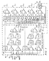
- FIG. 1 which is identical to FIG. 4 in U. S. Patent Application No. 08/742,460 , shows a block diagram of the first part of the decoder, a two channel to five channel matrix 90.
- the left half of FIG. 1 partitioned by a vertical dashed line shows a means for deriving the two steering voltages l / r and c / s. These voltages represent the degree to which the input signals have an inherent or encoded directional component in the left/right or front/back directions respectively.
- This part of the FIG. will not be explicitly discussed in this application as it has been fully described in the above patent application.
- the directional detection means of decoder 90 comprising elements 92 through 138 -is followed by a 5 x 2 matrix to the right of the vertical dashed line.
- the elements of this matrix 140 through 158 determine the amount of each input channel that is linearly combined with the other input channel to form each output channel.
- These matrix elements are assumed to be real. (The case of complex matrix elements was described in U. S. Patent Application No. 08/742,460 and will not be discussed here.)
- the matrix elements are functions of the two steering voltages l / r and c / s.
- U. S. PatentApplication No. 08/742,460 presented mathematical formulae for these functions. Part of the novelty in this application lies in improvements to these formulae. We present these formulae graphically and give an explanation for why they take the shape they do.
- the steering voltages c / s and l / r are derived from the logarithm of the ratio of the left input amplitude at terminal 92 to the right input amplitude at terminal 94, and the logarithm of the ratio of the sum amplitude to the difference amplitude.
- l / r and c/s as angles that vary from +45 degrees to --45 degrees.
- these voltages have the units of decibels.
- the angles lr and cs determine the degree to which the input signals have a directional component. For example, when the inputs to the decoder are decorrelated, both lr and cs are zero. For a signal that comes from the center only, lr is zero, and cs has the value 45 degrees. For a signal that comes from the rear, lr is zero, and cs is -45 degrees. Similarly, a signal that comes from the left has an lr value of 45 degrees and a cs value of zero, and a signal from the right has an lr value of -45 degrees, and a cs value of zero.
- the matrix elements shown in FIG. 1 are real and thus frequency independent. All signals in the inputs will be directed to the outputs depending on the derived angles lr and cs. (In the current art low frequencies and very high frequencies are attenuated in the derivation of lr and cs from the input signals by filters not shown in FIG. 1 . However, the matrix itself is broadband.)
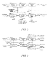
- FIG. 2 shows a five channel version of the additional frequency dependent circuits. These circuits do not have fixed parameters. The frequency and level behavior is dependent on the steering values lr and cs. The circuits accomplish several purposes. First, in both a five channel and a seven channel decoder, the additional elements allow the apparent loudness of the rear channels to be adjusted when the steering is neutral (lr and cs 0) or toward the front ( cs > 0). In U. S. Patent Application No. 08/742,460 this attenuation was performed as part of the matrix itself. and was frequency independent. We have found with theoretical studies and listening tests that it is highly desirable for the low frequencies to be reproduced from the sides of the listener. Thus in the decoder presented here only the high frequencies are attenuated by variable low pass filters 182, 184, 188, and 190.
- Further elements 192, 194 in the five channel version modify the spectrum of the sound when the steering is toward the rear ( cs ⁇ 0) using the c / s signal 196 such that the loudspeakers seem to be located behind the listener, even if their actual position is to the side.
- the modified left surround and right surround signals appear at terminals 198 and 200, respectively. Additional details of this circuit will be given in a later section of this disclosure.
- FIG. 3 shows the seven channel version of the frequency dependent elements.
- the first set of filters 182, 184, 188, 190 attenuate the upper frequencies of the side and rear outputs when the steering is neutral or forward, again controlled by the background control signal 186. This attenuation also results in a more forward sound image, and can be adjusted to the listener's taste.
- additional circuits 202, 204, 206, 208 act to differentiate the side outputs from the rear outputs. As steering moves rearward the attenuation mentioned above in the side speakers is first removed by elements 204 and 206 to produce a side oriented sound.
- FIG. 4 shows a block diagram of an encoder according to an example, which is useful for understanding the invention.
- the encoder is designed to automatically mix five input channels into two output channels.
- the architecture is quite different from the encoder described in U. S. Patent Application No. 08/742,460 .
- the object of the new design is to preserve the musical balances of the five channel original, while providing phase/amplitude cues that allow the original five channels to be extracted by the decoder.
- the previous encoder had similar goals, but there have been improvements in the methods used to achieve these goals.
- the preservation of musical balances is highly important in the encoder.
- One of the primary purposes of the encoder is to automatically create a two channel mix of a five channel recording, that will play in an ordinary two channel system with the same artistic quality as the five channel original.
- the new encoder design includes active elements to ensure that musical balance is preserved.
- the new design allows input signals to be panned between any of the five inputs of the encoder. For example, a sound may be panned from the left front input to the right rear input.
- the resulting two channel signal is decoded by the decoder described in this application the result will be quite close to the original sound. Decoding through an earlier surround decoder will also be similar to the original.
- the most basic goals of the current invention are identical to the goals of our previous decoders, particularly the one described in U. S. Patent Application No. 08/742,460 - "The invention is a surround sound decoder having variable matrix values so constructed as to reduce directionally encoded audio components in outputs which are not directly involved in reproducing them in the intended direction; enhance directionally encoded audio components in the outputs which are directly involved in reproducing them in the intended direction so as to maintain constant total power for such signals; while preserving high separation between the left and right channel components of non-directional signals regardless of the steering signals; and maintaining the loudness defined as the total audio power level of non-directional signals effectively constant whether or not directionally encoded signals are present and regardless of their intended direction if present.”
- the front input signals L, C and R are applied to input terminals 50, 52 and 54 respectively.
- L and R go directly to the adders 278 and 282 respectively, while the C signal is first attenuated by a factor fcn in attenuator 372 before being applied to inputs of both adders 2 78 and 282.
- the low frequency effects signal LFE is passed through a gain of 2.0 in element 374 and then applied to both adders 278 and 282.
- the surround input signals LS and RS are applied through two input terminals 62 and 64 respectively each to two separate paths: for the LS signal, the path through attenuator 378 has gain fs(l,ls) and the RS signal passes through a corresponding attenuator 380 with gain fs(r,rs).
- the outputs of these are passed into cross-coupling elements 384 and 386 having a gain factor of - crx , where crx is nominally 0.383.
- the cross-coupled signals from these elements are fed to summers 392 and 394 which also receive the attenuated LS and RS signals from 0.91 attenuators 388 and 392.
- the outputs of summers 392, 394 are applied to inputs of the adders 278, 282. This positions the elements respectively at 45 degrees left and right of center rear in the decoded space.
- the other signal branch passes the LS and RS signals through attenuators 376 with gain fc(l,ls) and 382 with gain fc ( r,rs ) respectively, and then through a similar arrangement of cross-coupling elements 396, 398, 402, 404, 406, and 408, the summers 406 and 408 having outputs representing left rear and right rear inputs at 45 degrees left and right of center rear, as before.
- these signals now each pass through phase shifter elements 234 and 246 respectively, while the left and right signals from adders 278 and 282 pass through phase shifter elements 286 and 288 respectively.
- phase shifter elements is an all-pass filter, the phase response being ⁇ ( f ) for elements 286 and 288, and ⁇ ( f )-90° for elements 234 and 246. Calculation of the component values required in these filters is well known in the art, and will not be discussed further here. The result is that the outputs of summers 406 and 408 are caused to lag those of adders 278 and 282 by 90 degrees at all frequencies after passage through the all-pass filter networks as shown in FIG. 4 .
- the gain functions fs and fc are designed to allow strong surround signals to be presented in phase with the other sounds while weak surround signals pass through the 90 degree phase-shifted path to retain constant power for decorrelated "music" signals.
- the value of crx can also change, and varies the angle from which the surround signals are heard.
- both the left decoder Input and the right decoder input will be reproduced by the center speaker, and sounds that were originally only in the left (or right) channel will also be reproduced from the center.
- the result must be that the apparent positions of these sounds will be drawn to the middle of the room. The degree to which this occurs depends on the loudness of the center channel.
- U. S. Patents Nos. 4,862,502 and 5,136,650 used matrix elements that had a minimum value of 3dB compared to the left and right channels. When the inputs to the decoder were decorrelated the loudness of the center channel was equal to the loudness of the left and right channels. As steering moved forward the center matrix elements increased another 3dB. The effect of this high loudness is to strongly reduce the width of the front image. Instruments that should have sounded at the left and the right of the sound image are always drawn toward the center of the sound image.
- U. S. Patent Application No. 08/742,460 used center matrix elements that had a minimum value 4.5dB less than the earlier values. This minimum value was chosen on the basis of listening tests. This attenuation causes a pleasing spread to the front image when the input material is uncorrelated - as with orchestral music. The front image is not seriously narrowed. In U. S Patent Application No. 08/742,460 as the steering moved forward these matrix elements increased, ultimately reaching the values used in the Dolby matrix.
- the decoder of V1.11 used the matrix elements of U. S. Patent No. 4,862,502 for the front channels under these conditions. These matrix elements do not fully eliminate a rear steered signal unless it was steered to the full rear position - half way between left rear and right rear. When steering was to left rear or right rear (not full rear) the left or right front output had an output 9dB less than the corresponding rear output.
- the front matrix elements are modified to eliminate sound from the front when steering is anywhere between left rear and right rear.
- the improvements to the rear matrix elements are not immediately obvious to a typical listener. These improvements correct various errors in the continuity of the matrix elements across the boundaries between quadrants. They also improve the power balance between steered signals and unsteered signals under various conditions. The mathematical description of the matrix elements that will be given later includes these improvements.
- Matlab The math used to describe the matrix elements is not based on continuous functions of the variables cs and lr. In general there are conditionals, absolute values, and other non-linear modifications to the formulae. For this reason we will describe the matrix elements using a programming language.
- phase/amplitude decoders determine the apparent direction of the input by comparing the ratio of the amplitudes of the input signals. For example, the degree of steering in the right/left direction is determined from the ratio of the left input channel amplitude to the right input channel amplitude. In a similar way, the degree of steering in the front/back direction is determined from the ratio of the amplitudes of the sum and the difference of the input channels.
- Logic 7 decoders differ from standard decoders significantly in how this is done. We assume that the steering directions have been determined.
- the two steering directions have their maximum value. However under these conditions they are not independent.
- the advantage to representing the steering values as angles is that when there is only a single signal the absolute value of the two steering values must sum to 45 degrees.
- the input includes some decorrelated material along with a strongly steered signal, the sum of the absolute values of the steering values must be less than 45 degrees. lr + cs ⁇ 45 If we plot the values of the matrix elements over a two-dimensional plane formed by the steering values, the center of the plane will have the value (0, 0) and the legal values for the sum of the steering values will not exceed 45 .
- the elements presented here are not always correctly scaled. In general they are presented so that the unsteered value of the of the non-zero matrix elements are for any given channel is one. In practice the elements are usually scaled so the maximum value of each element is one or less. In any case, in a final product the scaling of the elements is additionally varied in the calibration procedure.
- the matrix elements presented here should be assumed to be scalable by appropriate constants.
- cs and lr are the steering directions in degrees in the center/surround and left/right axis respectively.
- G( x ) was determined experimentally in the 1989 patent, and is specified mathematically in the '91 patent. It varies from 0 to 1 as x varies from 0 to 45 degrees.
- G( x ) can be shown to be equal to 1-
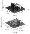
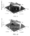
- G( x ) can also be described in terms of the steering angles using various formulae. One of these is given in the '91 patent, and another will be given later in this document. See FIG. 5 and FIG. 6 for graphical representations of the LFL and LFR matrix elements plotted three-dimensionally against the lr and cs axes.
- FIG. 7 shows the sum of the squares of these elements, demonstrating that the above matrix elements do not meet the requirement of constant loudness.
- the value is constant at .71 along the axis from unsteered to right.
- the unsteered to left rises 3dB to the value one, and the unsteered to center or to rear falls by 3dB to the value 0.5.
- This part of the graph is hidden by the peak at left.
- the rear direction level is identical to that at the center direction.
- G(x) 1 - tan 45 - x
- boost 1 (cs) as used in March 1997 was a linear boost of 3dB total applied over the first 22.5 degrees of steering, decreasing back to 0dB in the next 22.5 degrees.
- Boost( cs ) is given by corr( x ) in the Matlab code below (comment lines are preceded by the percent symbol %).
- the performance of the March 1997 circuit can be improved.
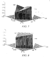
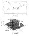
- the first problem is in the behavior of the steering along the boundaries between left and center, and between right and center. As a strong single signal pans from the left to the center, it can be seen in FIG. 9 that the value of the LFL matrix element increases to a maximum half-way between left and center. This increase in value is an unintended consequence of the deliberate increase in level for the left and right main outputs as a center signal is added to stereo music.
- LFL and LFR in the front right quadrant are similar, but without the +0.41*G term. These new definitions lead to the matrix element shown graphically in FIG. 10 .
- LFL cos t * F t - / + sin t * sqrt ⁇ 1 - F ⁇ t ⁇ ⁇ 2
- LFR ( sin t * cos 4 * t - cos t * sin 4 * t
- FIG 12 which views the coefficient graph from left rear, note the large correction along the left-rear boundary. This causes the front left output to go to zero when steering goes from left to left rear. The output remains zero as the steering progresses to full rear.
- the function is identical to the Dolby matrix.
- the unsteered (middle) to right axis has the value one
- the center vertex has the value 0.71
- the rear vertex has the value 0.5
- the left vertex has the value 1.41. Note the peak along the middle to center axis.
- the Dolby elements are similar to our '89 patent elements, but without the boost dependent on cs in the rear. This difference is in fact quite important, as after the standard calibration procedure the elements have quite different values for unsteered signals.
- our description of the matrix elements does not consider the calibration procedure for these decoders. We derive all the matrix elements with a relatively arbitrary scaling. In most cases the elements are presented as if they had a maximum value of 1.41. In fact, for technical reasons the matrix elements are all eventually scaled so they have a maximum value of less than one. In addition, when the decoder is finally put to use, the gain of each output to the loudspeaker is adjusted.
- the 3dB difference in the elements in the forward steered or unsteered condition is not trivial.
- the elements from the '89 patent have the value 0.71, and the sum of the squares of the elements has the value of one. This is not true of the Dolby rear elements when calibrated.
- LRL has the unsteered value of one, and the sum of the squares is 2, or 3dB higher than the '89 outputs.
- the calibration procedure results in a matrix that does not correspond to a "Dolby Surround" passive matrix when the matrix is unsteered.
- the Dolby Surround passive matrix specifies that the rear output should have the value of .71*(A in - B in ), and the Pro-Logic matrix does not meet this specification.
- the sound power in the room will be proportional to L in 2 + R in 2 + C in 2 . If all three components have roughly equal amplitudes, the power ratio of the center component to the left plus right component will be 1:2.
- the major problem with both the '89 elements and the Dolby elements is that there is only a single rear output.
- the '91 patent disclosed a method for creating two independent side outputs, and the math in that patent was incorporated in the front left quadrant in reference [1] of 1996 and the application No. 08/742,460 .
- the goal of the elements in this quadrant was to eliminate the output of a signal steered from left to center, while maintaining some output from the left rear channel for unsteered material present at the same time.
- the LRL matrix element would have the following form:
- these matrix elements are very similar to the '89 elements, but with the addition of a G(lr) term in LRR, and a GS term in LRL.
- G( lr ) was included to add signals from the B input channel of the decoder to the left rear output, to provide some unsteered signal power as the steered signal was being removed.
- GS(lr) the criterion, that there should be no signal output with a fully steered signal moving from left to center.
- the formula for GS(lr) turned out to be equal to G 2 (lr), although a more complicated representation of the formula is given in the '91 patent. The two representations can be shown to be identical.
- FIG. 18 shows several problems with the sound power.
- This dip exists because of the functional shape of G( lr ) in LRR is not optimal.
- the choice of G( lr ) was arbitrary - in the earlier design this function already existed in the decoder, and its implementation in analog circuitry is easy.
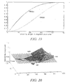
- FIG. 20 in this application shows the matrix elements without the "tv matrix” correction. In this application this correction is handled by the frequency dependent circuitry that follows the matrix and will be described later.
- the interpolation causes the value to match the value of GS( lr ) when cs is zero, and allows the value to rise smoothly to the value given by the previous math as cs increases negatively toward the rear.
- the steered component of the input should be removed from the left outputs - there should be no output from the rear left channel when the steering is toward the right or right rear.
- the matrix elements given in the '91 patent achieve this goal. They are essentially the same as the rear matrix elements in the 4 channel decoder, with the addition of the sin( cs )+ cos( cs ) correction for the unsteered loudness.
- Rboost(cs) is defined in reference [1] and application No. 08/742,460 . It is closely equivalent to the function 0.41*G(cs) in the earlier matrix elements, except that rboost( cs ) is zero for 0 > cs > -22.5, and varies from zero to 0.41 as cs varies from -22.5 degrees to -45 degrees. Its exact functional shape is determined by the desire to keep the loudness of the rear output constant as sound is panned from left rear to full rear.
- the behavior of the Left Rear Left and Left Rear Right elements is much more complex.
- the Left Rear Left element must quickly rise from zero to near maximum as lr decreases from 4.5 to 22.5, or to zero.
- LRL is computed with interpolation, just as for LRR.
- Matlab notation In Matlab notation:
- the middle of the graph, and the right and rear vertices have the value 1.
- the center vertex has the value 1.41. In practice this element is scaled so the maximum value is one.
- the boost function of cs starts at zero as before, and rises with cs in such a way that CL and CR increase 4.5dB as cs goes from zero to 22.5 degrees.
- the increase is a constant number of dB for each dB of increase in cs.
- the boost function then changes slope, such that in the next 20 degrees the matrix elements rise another 3dB, and then hold constant.
- the new matrix elements are equal to the neutral values of the old matrix elements.
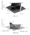
- the output of the center channel is thus 4.5dB less than the old output when steering in neutral, but rises to the old value when the steering is fully to the center. See FIG. 22 for a plot in three dimensions of this element.
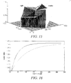
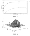
- FIG. 23 shows the center gain needed (solid curve) if the energy of the center component of the input signal is to be preserved in the front three channels as steering increases toward the front.
- the needed rise in the level of the center channel is quite steep - the rise is many dB of amplitude per dB of steering value.
- the gain in a standard decoder (dotted curve).
- the function (0.42 + GC( cs )) is plotted in FIG. 2 . 5 . Note the quick rise from the value 0.42 (45dB lower than Dolby surround), followed by a gentle rise, followed finally by a steep rise to the value 1..
- LFL GP cs
- RATIO C in 2 / L in 2 * 0.5
- the solid curve is the graph of GF needed for constant energy ratios with the new "music" center attenuation GC.
- the dashed curve is the LFR element of March '97, sin( cs )*corr1.
- the dotted curve is sin(cs), the LFR element without the correction term corr1. Note that GF is close to zero until cs reaches 30 degrees, and then increases sharply. We have found in practice it is best to limit the value of cs at about 33 degrees. In practice LFR derived from these curves has a negative sign.
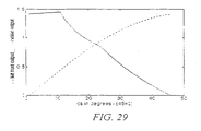
- FIG 29 which is a graph of the left front (dotted curve) and center (solid curve) outputs, note that center steering is at the left of the plot, and full left is at the right.
- cs the value of cs to about 33 degrees, (about 13 on the axis as labeled) where the center is about 6dB stronger than the left.
- the Logic 7 encoder There are two major goals of the Logic 7 encoder. Firstly, it should be able to encode a 5.1 channel tape in a way that allows the encoded version to be decoded by a Logic 71 decoder with minimal subjective change. Secondly, the encoded output should be stereo compatible - that is, it should sound as close as possible to a manual two channel mix of the same material. One factor in this stereo compatibility should be that the output of the encoder, when played on a standard stereo system, should give identical perceived loudness for each sound source in an original 5 channel mix. The apparent position of the sound source in stereo should also be as close as possible to the apparent position in the 5 channel original.
- the new encoder handles the left, center, and right signals identically to the previous design and identically to the Dolby encoder, providing the center attenuation function fcn is equal to 0.71, or -3dB.
- the surround channels look more complicated than they are.
- the functions fc () and fs () direct the surround channels either to a path with a 90 degree phase shift relative to the front channels, or to a path with no phase shift.
- fc In the basic operation of the encoder fc is one, and fs is zero - that is, only the path which uses the 90 degree phase shifts is active.
- the value crx is typically 0.38. It controls the amount of negative cross feed for each surround channel. As in the previous encoder, when there is only an input to one of the surround channels the A and B outputs have an amplitude ratio of -.38/.91, which results in a steering angle of 22.5 degrees to the rear. As usual, the total power in the two output channels is unity - that is the sum of the squares of .91 and .38 is one.
- a major function of the function fc in the surround channels is to reduce the level of the surround channels in the output mix by 3dB when the surround channels are much softer than the front channels. Circuitry is provided to compare the front and rear levels, and when the rear is less by 3dB, the value of fc is reduced to a maximum of 3dB. The maximum attenuation is reached when the rear channels are 8dB less strong than the front channels.
- This active circuit appears to work well. It makes the new encoder compatible with the European standard encoder for classical music. The action of the active circuits causes instruments which are intended to be strong in the rear channels to be encoded with full level.
- Level detecting circuits look at the phase relationship between the center channel and the front left and right. Some popular music recordings that use five channels mix the vocals into all three front channels. When there is a strong signal in all three inputs the encoder output will have excessive vocal power, since the three front channels will add together in phase. When this occurs, active circuits increase the attenuation in the center channel by 3dB to restore the power balance in the encoder output.
- FIG. 2 shows a block diagram of the frequency dependent circuits that follow the matrix in a five channel version of the decoder.
- the HRTF filter changes its characteristics depending on the value of the rear steering voltage c/s.
- the first two filters change their characteristics in response to a signal that is intended to represent the average direction of the input signals to the decoder during pauses between strongly steered signals. This signal is called the background control signal.
- One of the major goals of the current decoder is to be able to optimally create a five channel surround signal from an ordinary two channel stereo signal. It is also highly desirable that the decoder should recreate a five channel surround recording that was encoded into two channels by the encoder described as part of this application. These two applications differ in the way the surround channels are perceived. With an ordinary stereo input the majority of the sound needs to be in front of the listener. The surround speakers should contribute a pleasant sense of envelopment and ambience, but should not draw attention to themselves. An encoded surround recording needs the surround speakers to be stronger and more aggressive.
- the background control signal is designed to make this discrimination.
- the background control signal (BCS) is similar to and derived from the rear steering signal cs.
- BCS represents the negative peak value of cs. That is, when cs more negative than BCS, then BCS is made to equal cs. When cs is more positive than BCS the value of BCS slowly decays. However the decay of BCS involves a further calculation.
- Music of many types consists of a series of strong foreground notes - or in the case of a song, sung words. In between the foreground notes there is a background.
- the background may consist of other instruments playing other notes, or it may consist of reverberation.
- the circuit that derives the, BCS signal keeps track of the peak level of the foreground notes. When the current level is -7dB less than the peak level of the foreground, the level of cs is measured. The value of cs during these gaps between foreground peaks is used to control the decay of BCS. If the material in the gaps between notes is reverberation, it may tend to have a net rearward bias in a recording that was made by encoding a five channel original. This is because the reverberation on the rear channels of the original will be encoded with a rearward bias. The reverberation in an ordinary two channel recording will have no net rearward bias. Cs for this reverberation will be zero or slightly forward.
- BCS derived in this way tends to reflect the type of recording. Any time there is significant rear steered material BCS will always be strongly negative. However BCS can be negative even in the absence of strong steering to the rear if there the reverberation in the recording has a net rearward bias. We can use BCS to adjust the filters that optimize the decoder for stereo vs surround inputs.
- the first of the filters in FIG. 2 is a simple 6dB per octave low pass filter, with an adjustable cutoff frequency.
- this filter When BCS is positive or zero this filter is set to a value that is user adjustable, but is typically about 4kHz. As BCS becomes negative the cutoff frequency is raised, until when BCS is more rearward than 22 degrees the filter is not active. This low frequency filter makes the rear outputs less obtrusive when ordinary stereo material is played.
- the filter has been a part of the decoder at least since V1.11, but in the earlier decoders it was controlled by cs , and not by BCS.
- the second filter is a variable shelf filter.
- the low frequency section (the pole) of this filter is fixed, at 500 Hz.
- the high frequency section (the zero) varies depending on user adjustment and on BCS.
- This filter implements the "soundstage" control in the current decoder.
- "soundstage" is implemented through the matrix elements, using the "tv matrix” correction.
- the earlier decoders based on this work reduced the overall level of the rear channels when the steering was neutral or forward. In the new decoder presented here the matrix elements do not include the "tv matrix” correction.
- the high frequency section of the shelf filter is set equal to the low frequency section - in other words the shelf has no attenuation. and the filter has flat response.
- the third filter is controlled by c / s and not by BCS.
- This filter is designed to emulate the frequency responses of the human head and pinnae when a sound source is approximately 150 degrees in azimuth from the front of the listener.
- This type of frequency response curve is called a "Head Related Transfer Function" or HRTF.
- HRTF Head Related Transfer Function
- the current standard for five channel sound reproduction recommends that the two rear speakers be placed slightly behind the listener, at +/-110 or 120 degrees from the front. This speaker position supplies good envelopment at low frequencies.
- a sound from the side a listener does not produce the same level of excitement as a sound that is fully behind a listener.
- a listening room does not have a size or shape that is appropriate to place the loudspeakers fully behind the listener, and a side position is the best that can be achieved.
- the HRTF filter in the decoder adds the frequency notches of a rear sound source, so that a listener hears the sound as further behind that the actual position of the loudspeaker.
- the filter is designed to vary with cs. When cs is positive or zero, the filter is maximum. This causes ambient sounds and reverberation to seem to be more behind the listener. As cs becomes negative the filter is reduced. When cs is approximately -15 degrees the filter is completely removed, and the sound source appears to come fully from the side. As cs goes further negative the filter is once again applied, so the sound source appears to go behind the listener. When cs is fully to the rear the filter is slightly modified to correspond to the HRTF function for a sound fully to the rear.
- FIG. 3 shows the frequency dependent circuits the seven channel version of the decoder. These are shown as consisting of three sections - although in an actual implementation the second two sections can be combined into one circuit.
- the first two sections are identical to the two sections in the five channel decoder, and perform the same function.
- the third section is unique to the seven channel decoder.
- the side and the rear channels had separate matrix elements. The action of the elements was such that when cs was positive or neutral the side and the rear outputs were identical except for delay. The two outputs stayed identical until cs was more negative than 22 degrees. As the steering moved further to the rear the side outputs were attenuated by 6dB, and the rear outputs were boosted by 2dB. This caused the sound to appear to move from the sides of the listener to the rear of the listener.
- the differentiation between the side output and the rear output is achieved by a variable shelf filter in the side output.
- the third shelf filter in FIG. 3 has no attenuation when cs is forward or zero. When cs becomes more negative than 22 degrees the zero in the shelf filter moves rapidly toward 1100Hz, resulting in an attenuation of the high frequencies of about 7dB.
- this shelf filter has been described as a separate filter from the shelf filter that provides the "soundstage" function, the action of the two shelf filters can be combined into a single shelf through suitable control circuitry.
Description
- This invention relates to sound reproduction systems involving the decoding of a stereophonic pair of input audio signals into a multiplicity of output signals for reproduction after suitable amplification through a like plurality of loudspeakers arranged to surround a listener.
- The present invention concerns an improved set of design criteria and their solution to create a decoding matrix having optimum psychoacoustic performance in reproducing encoded multichannel material as well as standard two channel material, that includes maintaining high separation between left and right components of stereo signals under all conditions, even when there is a net forward or rearward bias to the input signals, or when there is a strong sound component in a particular direction, while maintaining high separation between the various outputs for signals with a defined direction, and while maintaining non-directionally encoded components at a constant acoustic level regardless of the direction of directionally encoded components of the input audio signals, including frequency dependent circuitry that improves the balance between front and rear signals, provides smooth sound motion around a seven channel version of the system, and makes the sound of a five channel version closer to that of a seven channel version.
- The present invention is part of a continuing effort to refine means for separating two channels into the multichannel signals from which they were derived. One of the goals of this decode process is to recreate the original signals as perceptually identical to the originals as possible. Another important goal of the decoder is to extract five or more separate channels from a two channel source that was not encoded from a five channel original. The resulting five channel presentation must be at least as musically tasteful and enjoyable as the original two channel presentation.
- The present invention is concerned with improvements to the derivation of suitable variable matrix coefficients. To assist understanding of these improvements, this disclosure makes reference to Griesinger's
U.S. Patent No. 4,862,502 (1989 ) which will be referred to as the '89 patent:U.S. Patent No. 5,136,650 (1992 ), which will be referred to as the '92 patent; theJuly 1996 Griesinger U.S. Patent Application No. 08/684,948 November 1996 Griesinger U.S. Patent Application No. 08/742,460 Provisional Patent Application 60/058,169 filed September 1997 Logic 7" decoders. - Additional technical references cited are: [1] "Multichannel Matrix Surround Decoders for Two-Eared Listeners," David Griesinger. AES preprint # 4402, October, 1996, and [2] "Progress in 5-2-5 Matrix Systems," David Griesinger, AES preprint # 4625, September, 1997.
- The means employed to realize the two goals of recreating the original signals encoded from five to two channels and of creating a perceptually satisfactory reproduction of two channel material in a five channel format have evolved as we continue to better understand the physics and the psychoacoustics involved. The previous patents and patent applications referred to above presented a design philosophy that produced useful decoder devices.
- The present invention is concerned with the realization of an active matrix having certain properties that maximize its psychoacoustic performance. In another aspect it discloses frequency dependent modification of certain of the outputs from the active matrix. The present invention is defined in
claim 1. - The invention is in part an active matrix decoder having matrix elements that vary depending on the directional component of the incoming signals. The matrix elements vary in such a way as to reduce the loudness of directionally encoded signals in outputs that are not involved in the intended direction, while enhancing the loudness of these signals in directions that are involved in reproducing the intended direction, while preserving at all times the left/right separation of other signals that may be present at the same time at the inputs. Moreover, matrix elements in accordance with the invention restore the left/right separation of decorrelated two channel material that has been directionally encoded by increasing or decreasing the blend between the two inputs - for example with a stereo width control. In addition matrix elements in accordance with the invention are designed to preserve as much as possible the energy balance between various components of the input signal, such that the balance between vocals and accompaniment is preserved in the decoder outputs. As a consequence matrix elements in accordance with the invention preserve both the loudness of non directionally encoded elements of the input sound and the left/right separation of these elements.
- Additionally, decoders in accordance with preferred embodiments of the invention include frequency dependent circuits that improve the compatibility of the decoder outputs when standard two channel material is played, that convert the surround outputs from two for a five channel decoder to four for a seven channel decoder, and that modify the spectrum of the rear channels in a five channel decoder so that the sound direction appears to be more like the sound direction from a seven channel decoder.
- The novel features believed characteristic of the present invention are set forth in the appended claims. The invention itself, as well as other features and advantages thereof, will best be understood by reference to the following detailed description of an illustrative embodiment when read in conjunction with the accompanying drawing figures, wherein:
-
FIG. 1 is a block schematic of a direction detection section and a two to five channel matrix section of a decoder according to the present invention, but not including aspects further shown inFIGs. 2 and 3 ; -
FIG. 2 is a block schematic of a five-channel frequency- dependent active signal processor circuit which may be connected between the outputs of the matrix section of FIG. I and the decoder outputs; -
FIG. 3 is a block schematic of a five-to-seven channel frequency-dependent active signal processor which may alternatively be connected between the outputs of the matrix section of FIG. I and the decoder outputs; -
FIG. 4 is a block schematic of an active five-channel to two-channel encoder according to an example which is useful for understanding the invention; -
FIG. 5 is a three-dimensional graphical representation of the prior art Left Front Left (LFL) matrix element from the '89 patent and Dolby Pro-Logic, scaled so the maximum value is one; -
FIG. 6 is a three-dimensional graphical representation of the prior art Left Front Right (LFR) matrix element from the '89 patent and Dolby Pro-Logic, scaled by.71 so the minimum value is -0.5 and the maximum value is + 0.5; -
FIG. 7 is a three-dimensional graphical representation of the square root of the sum of the squares of the prior art LFL and-LFR from the '89 patent, scaled so the maximum value is one; -
FIG. 8 is a three -dimensional graphical representation of the square root of the sum of the LFL and LFR matrix elements from application No. 08/742,460, scaled so the max value is 1; -
FIG. 9 is a three-dimensional graphical representation of the Left Front Left (LFL) matrix element in V1.11; -
FIG. 10 is a three-dimensional graphical representation of the partially completed Left Front Left matrix element in the present invention: -
FIG. 11 is a graph showing the behavior of LFL and LFR in the present invention along the rear boundary between left and full rear; -
FIG. 12 is a three-dimensional graphical representation of the fully completed Left Front Left (LFL) matrix element in the present invention as viewed from the left rear; -
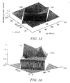
FIG. 13 is a three-dimensional graphical representation of the fully completed Left Front Right (LFR) matrix element in the present invention: -
FIG. 14 is a three-dimensional graphical representation of the root mean squared sum of LFL and LFR according to the present invention: -
FIG. 15 is a three-dimensional graphical representation of the square root of the sum of the squares of LFL and LFR according to the present invention, including the correction to the rear level, viewed from the left rear; -
FIG. 16 is a graph showing with the solid curve the center matrix elements that should be used in a prior art Dolby Pro-Logic decoder as a function of CS in dB, and with the dotted curve the actual value of the center matrix elements in the Dolby Pro-Logic decoder; -
FIG. 17 is a graph showing with the solid curve the ideal value of the center matrix elements, and with the dotted curve the actual values of the center matrix elements in prior art Dolby Pro-Logic; -
FIG. 18 is a three-dimensional graphical representation of the square root of the sum of the squares of LRL and LRR, using the prior art elements of V1.11; -
FIG. 19 is a graphical representation of the numerical solution for GS(lr) and GR(lr) for constant power level along the cs=0 axis, and zero output along the boundary between left and center; -
FIG. 20 is a three-dimensional graphical representation of the square root of the sum of the squares of LRL and LRR using the values for GR and GS according to the present invention; -
FIG. 21 is a three-dimensional graphical representation of the prior art Center Left (CL) matrix element of the '89 patent four channel decoder (and the Dolby Pro-Logic decoder) which can also represent the Center Right (CR) matrix element with left and right interchanged: -
FIG. 22 is a three-dimensional graphical representation of the Center Left (CL) matrix element inLogic 7 V1.11 decoders: -
FIG. 23 is a graph showing with the solid curve the center Output channel attenuation needed for the new LFL and LFR, and with the dotted curve the center attenuation for a standard prior art Dolby Pro-Logic decoder; -
FIG. 24 is a graph showing with the solid curve the ideal center attenuation for the "film" strategy, according to the present invention, with the dashed curve a value that works significantly better, and with the dotted curve the center attenuation for the standard Dolby decoder for comparison; -
FIG. 25 shows the center attenuation used in the "music" strategy in the present invention; -
FIG. 26 is a graph showing with the solid curve the value of GF needed for constant energy ratios with the "music" center attenuation GC of the present invention, with the dashed curve the previous LFR element sin(cs)*corr1, and with the dotted curve the value of sin(cs); -
FIG. 27 is a three-dimensional graphical representation of the Left Front Right (LFR) matrix element in the new invention, including the correction for center level along the lr= 0 axis; -
FIG. 28 is a three-dimensional graphical representation of the Center Left (CL) matrix element with the new center boost function; and -
FIG. 29 is a graph which plots the output level from the left front output (dotted curve) and the center output (solid curve) as a strong signal pans from center to left. - The design presented here preserves much of the design philosophy of the previous decoders. but the actual design has changed in many ways. It is not possible within the bounds of a document of readable length to completely describe the evolution of this design. To keep the document coherent we will present here the most important elements of the design philosophy, show the mathematical solutions to the problems presented, and make claims on the solutions that are original with this filing. It may be useful to consult our previous filings on this subject, but it should not be essential.
- Experience with the decoder as described in the July '96 and November '96 applications and the September '97 provisional patent application has led to additional improvements that have not yet been disclosed. This application will present the most essential features of the improved decoder of the present invention, and will make claims on the novel features that have been added since
U. S. Patent Application No. 08/742,460 . - The decoder in this application will be described as consisting of two separate parts. The first part is a matrix that splits the two input channels into five output channels, which are usually identified as center, left front, right front, left rear and right rear. The second part consists of a series of delays and filters that modify the spectrum and the levels of the two rear outputs. One of the functions of the second part is to derive an additional pair of outputs, left side and right side, when a seven channel version of the decoder is desired. In application No.
08/742,460 the second part was not explicit - the two additional channels were derived from an additional pair of matrix elements in the original matrix. - In mathematical equations describing the decoder we will use the standard typographical conventions for most variables, simple variables being shown in italics, while vector quantities are in bold lower case type and matrixes are represented by bold upper case type. Matrix elements that are coefficients from a named output channel resulting from a named input channel will be shown in normal upper case type. Some simple variables such as lr and cs are described by two-letter names which do not represent products of two separate simple variables. Other variables l/r and c/s do in some sense represent the values of left-right and center-surround ratios, but in terms of control signal voltages derived from these ratios. These conventions have also been used in the previous U. S. Patents and Patent Applications cited in this document. Program segments in the Matlab language will also be distinguished by the use of a different type face and point size and by indenting these lines. Equations will be numbered, to distinguish them from Matlab assignment statements, and to provide a reference for specific features described herein.
-
FIG. 1 , which is identical toFIG. 4 inU. S. Patent Application No. 08/742,460 , shows a block diagram of the first part of the decoder, a two channel to five channel matrix 90. The left half ofFIG. 1 partitioned by a vertical dashed line shows a means for deriving the two steering voltages l/r and c/s. These voltages represent the degree to which the input signals have an inherent or encoded directional component in the left/right or front/back directions respectively. This part of the FIG. will not be explicitly discussed in this application as it has been fully described in the above patent application. - In
FIG. 1 the directional detection means of decoder 90 comprisingelements 92 through 138 -is followed by a 5 x 2 matrix to the right of the vertical dashed line. The elements of thismatrix 140 through 158 determine the amount of each input channel that is linearly combined with the other input channel to form each output channel. These matrix elements are assumed to be real. (The case of complex matrix elements was described inU. S. Patent Application No. 08/742,460 and will not be discussed here.) The matrix elements are functions of the two steering voltages l/r and c/s.U. S. PatentApplication No. 08/742,460 presented mathematical formulae for these functions. Part of the novelty in this application lies in improvements to these formulae. We present these formulae graphically and give an explanation for why they take the shape they do. - As shown in
FIG. 1 , the steering voltages c/s and l/r are derived from the logarithm of the ratio of the left input amplitude atterminal 92 to the right input amplitude atterminal 94, and the logarithm of the ratio of the sum amplitude to the difference amplitude. In describing the matrix elements it is convenient to express l/r and c/s as angles that vary from +45 degrees to --45 degrees. In the decoders of V1.11 and V2.01 these voltages have the units of decibels. We can convert the steering parameters to angles, where

- The angles lr and cs determine the degree to which the input signals have a directional component. For example, when the inputs to the decoder are decorrelated, both lr and cs are zero. For a signal that comes from the center only, lr is zero, and cs has the
value 45 degrees. For a signal that comes from the rear, lr is zero, and cs is -45 degrees. Similarly, a signal that comes from the left has an lr value of 45 degrees and a cs value of zero, and a signal from the right has an lr value of -45 degrees, and a cs value of zero. We will assume in our design that the encoder that creates the encoded signal has the properties that when we encode a left rear signal lr = 22.5 degrees, and cs = 22.5 degrees. Similarly, a signal applied to the right rear input to the encoder produces values of lr=22.5 degrees, and cs=22.5 degrees. - From the definitions of l/r and c/s and the derivation of lr and cs, it can be seen that the stun of the absolute value of lr and cs cannot be greater than 45 degrees. The allowed values of lr and cs form a surface bounded by the locus of abs(lr)-abs(cs)=45 degrees. Any input signal that produces values of lr and cs that lie along the boundary of this surface is fully localized - that is it consists of a single sound that has been encoded to come from a particular direction.
- In this application we will make extensive use of graphs of the matrix elements as functions over this two dimensional surface. In general the derivation of the matrix elements will be different in the four quadrants of this surface. In other words the matrix elements are differently described depending on whether the steering is forward or rearward, and whether it is to the left or the right. Considerable work is devoted to insuring that the surface is continuous across the boundaries between quadrants. The occasional lack of such continuity is one of the problems with the decoder of V1.11 that this application will address.
- The matrix elements shown in
FIG. 1 are real and thus frequency independent. All signals in the inputs will be directed to the outputs depending on the derived angles lr and cs. (In the current art low frequencies and very high frequencies are attenuated in the derivation of lr and cs from the input signals by filters not shown inFIG. 1 . However, the matrix itself is broadband.) - We have found in practice that there are several advantages to applying frequency dependent circuits to the signals after the matrix. One of these frequency dependent circuits - the
phase shift network 170 at theright side output 180 inFIG. 1 - has been described inU. S. Patent Application No. 08/742,460 and not be further discussed here. -
FIG. 2 shows a five channel version of the additional frequency dependent circuits. These circuits do not have fixed parameters. The frequency and level behavior is dependent on the steering values lr and cs. The circuits accomplish several purposes. First, in both a five channel and a seven channel decoder, the additional elements allow the apparent loudness of the rear channels to be adjusted when the steering is neutral (lr and cs 0) or toward the front (cs > 0). InU. S. Patent Application No. 08/742,460 this attenuation was performed as part of the matrix itself. and was frequency independent. We have found with theoretical studies and listening tests that it is highly desirable for the low frequencies to be reproduced from the sides of the listener. Thus in the decoder presented here only the high frequencies are attenuated by variable low pass filters 182, 184, 188, and 190. - This is accomplished by attenuating the frequencies above 500Hz in the rear channels by means of
elements elements background control signal 186 to be defined later in this application. Occasional presence of sounds that are steered rearwards reduces the attenuation, a feature that automatically distinguishes surround encoded material from ordinary two channel material. -
Further elements signal 196 such that the loudspeakers seem to be located behind the listener, even if their actual position is to the side. The modified left surround and right surround signals appear atterminals -
FIG. 3 shows the seven channel version of the frequency dependent elements. As before the first set offilters background control signal 186. This attenuation also results in a more forward sound image, and can be adjusted to the listener's taste. As the steering represented by the c/ssignal 196 moves to the rear,additional circuits elements elements delay elements 202, and 208. Since the low frequencies are not affected by these circuits, the low frequency loudness in the side speakers (which is responsible for the perception of spaciousness) is not affected by the motion of the sound. Again, a later section of this application will provide additional details of the circuitry inFIG. 3 . -
FIG. 4 shows a block diagram of an encoder according to an example, which is useful for understanding the invention. The encoder is designed to automatically mix five input channels into two output channels. The architecture is quite different from the encoder described inU. S. Patent Application No. 08/742,460 . The object of the new design is to preserve the musical balances of the five channel original, while providing phase/amplitude cues that allow the original five channels to be extracted by the decoder. The previous encoder had similar goals, but there have been improvements in the methods used to achieve these goals. The preservation of musical balances is highly important in the encoder. One of the primary purposes of the encoder is to automatically create a two channel mix of a five channel recording, that will play in an ordinary two channel system with the same artistic quality as the five channel original. The new encoder design includes active elements to ensure that musical balance is preserved. - Unlike the encoder of the November '97 application the new design allows input signals to be panned between any of the five inputs of the encoder. For example, a sound may be panned from the left front input to the right rear input. When the resulting two channel signal is decoded by the decoder described in this application the result will be quite close to the original sound. Decoding through an earlier surround decoder will also be similar to the original.
- A detailed description of the encoder will follow in a later section.
- The most basic goals of the current invention are identical to the goals of our previous decoders, particularly the one described in
U. S. Patent Application No. 08/742,460 - "The invention is a surround sound decoder having variable matrix values so constructed as to reduce directionally encoded audio components in outputs which are not directly involved in reproducing them in the intended direction; enhance directionally encoded audio components in the outputs which are directly involved in reproducing them in the intended direction so as to maintain constant total power for such signals; while preserving high separation between the left and right channel components of non-directional signals regardless of the steering signals; and maintaining the loudness defined as the total audio power level of non-directional signals effectively constant whether or not directionally encoded signals are present and regardless of their intended direction if present." - Most of these goals are ostensibly shared by all matrix decoders. The novelty in this application lies in part with knowing how to implement the above rule more accurately, and in part with knowing when not to apply the above rule. However much of the methodology of
U. S. Patent Application No. 08/742,460 is retained. One of the most important of the previous goals is the explicit maintenance of high separation between the left and right channels of the decoder under all conditions. All previous four channel decoders are unable to maintain separation in the rear, because they provide only a single rear channel. Five channel decoders from other manufacturers compromise separation in many ways. The decoder described in this application meets this goal in a similar way as that of V1.11- but it meets additional goals as well. -
U. S. Patent Application No. 08/742,460 also describes many smaller improvements to the design, such as circuits to improve the accuracy of the steering signals, and a variable phase shift network to switch the phase of one of the rear channels during strong rear steering. These features of the decoder V1.11 are retained in the new design, but will not be covered in this document. - In
FIG. 4 the front input signals L, C and R are applied to inputterminals adders attenuator 372 before being applied to inputs of bothadders 2 78 and 282. The low frequency effects signal LFE is passed through a gain of 2.0 inelement 374 and then applied to bothadders - The surround input signals LS and RS are applied through two
input terminals attenuator 378 has gain fs(l,ls) and the RS signal passes through acorresponding attenuator 380 with gain fs(r,rs). The outputs of these are passed intocross-coupling elements summers attenuators summers adders - The other signal branch passes the LS and RS signals through
attenuators 376 with gain fc(l,ls) and 382 with gain fc(r,rs) respectively, and then through a similar arrangement ofcross-coupling elements summers phase shifter elements adders phase shifter elements elements elements summers adders FIG. 4 . The outputs of all-pass networks summer 276 to produce the A (or left) output signal atterminal 44, while the outputs offilters summer 280 to produce the B (or right) output signal atterminal 46. - The gain functions fs and fc are designed to allow strong surround signals to be presented in phase with the other sounds while weak surround signals pass through the 90 degree phase-shifted path to retain constant power for decorrelated "music" signals. The value of crx can also change, and varies the angle from which the surround signals are heard.
- One of the most noticeable improvements in the present invention relative to that of
U. S. Patent Application No. 08/742,460 is the change in the center matrix elements and left and right front matrix elements when a signal is steered in the center direction. We learned that there were two problems with the center channel as previously encoded and decoded. The most obvious problem is that in a five channel matrix system the use of a center channel is inherently in conflict with the goal of maintaining as much left/right separation as possible. If the matrix is to produce a sensible output from conventional two channel stereo material, when the two input channels have no left/right component the center channel must be driven with the sum of the left and right input channels. Thus both the left decoder Input and the right decoder input will be reproduced by the center speaker, and sounds that were originally only in the left (or right) channel will also be reproduced from the center. The result must be that the apparent positions of these sounds will be drawn to the middle of the room. The degree to which this occurs depends on the loudness of the center channel. -
U. S. Patents Nos. 4,862,502 and5,136,650 used matrix elements that had a minimum value of 3dB compared to the left and right channels. When the inputs to the decoder were decorrelated the loudness of the center channel was equal to the loudness of the left and right channels. As steering moved forward the center matrix elements increased another 3dB. The effect of this high loudness is to strongly reduce the width of the front image. Instruments that should have sounded at the left and the right of the sound image are always drawn toward the center of the sound image. -
U. S. Patent Application No. 08/742,460 used center matrix elements that had a minimum value 4.5dB less than the earlier values. This minimum value was chosen on the basis of listening tests. This attenuation causes a pleasing spread to the front image when the input material is uncorrelated - as with orchestral music. The front image is not seriously narrowed. InU. S Patent Application No. 08/742,460 as the steering moved forward these matrix elements increased, ultimately reaching the values used in the Dolby matrix. - Experience with the V1.11 decoder showed that although the reduction in center channel loudness solved the spatial problem, the power balance in the input signals was not preserved through the matrix. Mathematical analysis revealed that not only was V1.11 in error, but the Dolby, decoder and our previous decoders were also in error. Paradoxically, although the center channel was too strong from the standpoint of reproducing the width of the front image, it was too weak to preserve power balance. The problem was particularly severe for the decoder of Mandel - the standard Dolby decoder. In the standard Dolby decoder the rear channels are stronger than in our decoder of patent No.
4,862,502 . As a result the center channel must be stronger to preserve power balance. The lack of power balance 'in the center channel has been a continual problem for the Dolby decoder. Dolby recommends that the sound mix engineer should always listen to the balance through the matrix, so the lack of power balance in the matrix can be compensated during the mixing process. Unfortunately modern films are mixed for five-channel release, and automatic encoding to two channels can lead to problems with the dialog level. - Additional analysis and listening tests showed that films and music require different solutions to the balance problem. For films we found that it was most useful to preserve the left and right front matrix elements from
U. S. Patent Application No. 08/742,460 . These elements eliminate the center channel information from the left and right front channels as much as possible. This minimizes dialog leakage into the front left and right channels. In the new "film" design the power balance is corrected by changing the center matrix elements so the center channel loudness increases more rapidly than the standard decoder as the steering moves forward (as cs becomes greater than zero.) In practice it is not necessary that the final value of the center matrix elements be higher than those in the standard decoder, as this condition is reached when only the center channel is active. It is only necessary that the center level be stronger than the standard decoder when there are approximately equal levels in the center channel and the left and right channels. - With the "film" strategy the center channel loudness is increased to preserve the power balance in the input signals, while minimizing the center channel component in all the other outputs. This strategy seems to be ideal for films, where the major use of the center channel is for dialog, and dialog from positions other than the center is not expected. The major disadvantage of this strategy is that anytime there is significant center steering - such as occurs in many types of popular music - the front image is narrowed. However the advantages for film - minimum dialog leakage into the front channels and excellent power balance - outweigh this disadvantage.
- For music we adopt another strategy. In this case we allow the center channel loudness to increase at the same rate as in
U. S. Patent Application No. 08/742,460 , up to a middle value of the steering, where cs ≥ 22.5 degrees. To restore the musical balance, we alter the left and right front matrix elements such that the center component of the input signals is not entirely removed. The amount of the center channel component in the left and right front is adjusted so that the sound power from all the outputs of the decoder matches the sound power in the input signals - without excessive loudness in the center. - With this strategy all three front speakers reproduce center channel information present in the original encoded material. The most useful version of this strategy limits the steering action at the point that the center component of the input is 6dB stronger in the center output than in either of the two other front outputs. This is done by simply limiting the positive value of cs.
- This new strategy - allowing the center channel component to come from all three front speakers, and limiting the steering action when the center is 6dB louder than the front left and right, turns out to be excellent for all types of music. Both encoded five-channel mixes and ordinary two-channel mixes decode with a stable center, and adequate separation between the center channel and the left and right. Note that unlike previous decoders the separation between center and left and right is deliberately not complete. A signal intended to come from the left is eliminated from the center channel, but not the other way around. For music the high lateral separation and stable front image that this strategy offers outweighs this lack of complete separation. Listening tests with this setting on films reveal that although there is some dialog coming from the left and right front speakers the stability of the resulting sound image is quite good. The result is pleasant and not distracting. For this listener hearing a film with the decoder set for music does not detract from the artistic quality of the film. Listening to a music recording, with the decoder set for film is more problematic.
- Possibly the next most obvious of the improvements in this application is the increase in separation between the front channels and the rear channels when a signal is steered to the left front or the left rear directions. The decoder of V1.11 used the matrix elements of
U. S. Patent No. 4,862,502 for the front channels under these conditions. These matrix elements do not fully eliminate a rear steered signal unless it was steered to the full rear position - half way between left rear and right rear. When steering was to left rear or right rear (not full rear) the left or right front output had an output 9dB less than the corresponding rear output. In the present invention the front matrix elements are modified to eliminate sound from the front when steering is anywhere between left rear and right rear. - The improvements to the rear matrix elements are not immediately obvious to a typical listener. These improvements correct various errors in the continuity of the matrix elements across the boundaries between quadrants. They also improve the power balance between steered signals and unsteered signals under various conditions. The mathematical description of the matrix elements that will be given later includes these improvements.
- The math used to describe the matrix elements is not based on continuous functions of the variables cs and lr. In general there are conditionals, absolute values, and other non-linear modifications to the formulae. For this reason we will describe the matrix elements using a programming language. The Matlab language provides a simple method of checking the formulation graphically. Matlab is very similar to Fortran or C. The major difference is that variables in Matlab can be vectors - that is each variable can represent an array of numbers in sequence. For example we can define the variable x in the following way:

- This specification in Matlab creates a string of ten numbers with the values of one to ten. The variable x includes all ten values. It is described a vector, a 1 by 10 matrix. An individual number within each vector can be accessed or manipulated. For example, the expression

will set the fourth member of the vector x to the value 4. Variables can also represent a two dimensional matrix. Individual elements in the matrix can be assigned in a similar way:
will assign thevalue 10 to the second row and third column of the matrix X. - The detailed description of the matrix elements that follows is nearly identical to the description published in reference [2]. The text has been somewhat improved. The major differences are:
- 1. Reference [2] includes the "tv matrix" feature. This feature reduces the level of the rear outputs when the steering is forward or neutral. In this application this function is achieved through the frequency dependent circuits that follow the matrix. Therefore we have left out the "tv matrix" correction.
- 2. The section on the center matrix elements has been modified to include references to the "film" strategy, the "music" strategy, and a strategy that limits the action of the "music" setting. Reference [21 described only the "music" setting, without the limit.
- In reference [1] we presented the design of a matrix decoder that can be described by the elements of a n x 2 matrix, where n is the number of output channels. Each output can be seen as a linear combination of the two inputs, where the coefficient of the linear combination are given by the elements in the matrix. In this paper the elements are identified by a simple combination of letters. Reference [1] described a five-channel and a seven-channel decoder. The conversion from five channels to seven channels is now done in the frequency dependent part of the decoder, so here we will describe a five-channel decoder only.
- It is obvious from symmetry that we need to describe the behavior of only six elements - the center elements, the two left front elements, and the two left rear elements. The right elements can found from the left by simply switching the identity of left and right. These elements are:
- CL:
- The matrix element for the Left input channel to the Center output
- CR:
- The matrix element for the Right input channel to the Center output
- LFL:
- The Left input channel to the Left Front output
- LFR:
- The Right input channel to the Left Front output
- LRL:
- The Left input channel to the Left Rear output
- LRR:
- The Right input channel to the Left Rear output
- These elements axe not constant. Their value varies as a two dimensional function of the apparent direction of the input sounds. Most phase/amplitude decoders determine the apparent direction of the input by comparing the ratio of the amplitudes of the input signals. For example, the degree of steering in the right/left direction is determined from the ratio of the left input channel amplitude to the right input channel amplitude. In a similar way, the degree of steering in the front/back direction is determined from the ratio of the amplitudes of the sum and the difference of the input channels. We will not discuss the method for determining these steering directions here, although
Logic 7 decoders differ from standard decoders significantly in how this is done. We assume that the steering directions have been determined. Here we will represent these directions as angles - one angle for the left/right direction (lr), and one for the front/back (center/surround) direction (cs). The two steering directions are signed variables. When both lr and cs are zero the input signals are unsteered -that is, the two input channels are uncorrelated. - When the input consists of a single signal which has been directionally encoded the two steering directions have their maximum value. However under these conditions they are not independent. The advantage to representing the steering values as angles is that when there is only a single signal the absolute value of the two steering values must sum to 45 degrees. When the input includes some decorrelated material along with a strongly steered signal, the sum of the absolute values of the steering values must be less than 45 degrees.

If we plot the values of the matrix elements over a two-dimensional plane formed by the steering values, the center of the plane will have the value (0, 0) and the legal values for the sum of the steering values will not exceed 45 . In practice, due to the behavior of the non-linear filters it is possible for the sum to exceed 45 - the application No. 08/742,460 claimed a circuit that limited the lessor of lr or cs so their sum did not exceed 45 degrees. This claim will not be further discussed here. We will assume the mathematics for the matrix elements is well behaved during overruns. When we graph the matrix elements we arbitrarily zero the values when the legal sum of the input variables is exceeded. This allows us to directly view the behavior of the element along the boundary trajectory - the trajectory followed by a strongly steered signal. The graphics were created by Matlab. In the Matlab language the unsteered position is (46, 46), because Matlab requires the angle variable to be 1 more than the actual angle value. Hopefully this will not be overly confusing. - Previous designs for matrix decoders tend to consider only the behavior of the matrix to a strongly steered signal - that is the behavior of the matrix elements around the boundary of our surface. This is a fundamental error in outlook. When you study real signals - either film or music - you find that the boundary of the surface is very seldom reached. For the most part signals wobble around the middle of the plane - slightly forward of the center. The behavior of the matrix under these conditions is of vital importance to the sound. When you compare our elements to previous elements you can see a striking increase in the complexity of the surface in the middle regions. It is this complexity which is responsible for the improvement in the sound.
- Such complexity has a price. Our original 1987 design - see the 1989 patent-was simple to implement with analog components. The new elements are designed to be almost entirely described by one-dimensional lookup tables, which are trivial in a digital implementation. Designing an analog version with similar performance is possible, but not trivial.
- In this application we contrast the several different versions of the matrix elements. The earliest are elements from our 1989 patent. These elements were used in our first surround processor, and are identical to the elements of a standard (Dolby) surround processor in the left, center, and right channels (but not identical in the surround channels.) In our design the surround channel is treated symmetrically to the center channel. In the standard (Dolby) decoder the surround channel is treated differently, and this issue will be discussed at length later in this application.
- The elements presented here are not always correctly scaled. In general they are presented so that the unsteered value of the of the non-zero matrix elements are for any given channel is one. In practice the elements are usually scaled so the maximum value of each element is one or less. In any case, in a final product the scaling of the elements is additionally varied in the calibration procedure. The matrix elements presented here should be assumed to be scalable by appropriate constants.
- Assume that cs and lr are the steering directions in degrees in the center/surround and left/right axis respectively.
- In the '89 patent the equations for the front matrix elements are given as:
- In the left front quadrant:


- In the right front quadrant:


- In the left rear quadrant (remember es is negative):


- In the right rear quadrant:


- The function G(x) was determined experimentally in the 1989 patent, and is specified mathematically in the '91 patent. It varies from 0 to 1 as x varies from 0 to 45 degrees. When steering is in the left front quadrant (lr and cs are both positive) G(x) can be shown to be equal to 1-|r|/|l| where |r| and |l| are the right and left input amplitudes. G(x) can also be described in terms of the steering angles using various formulae. One of these is given in the '91 patent, and another will be given later in this document. See
FIG. 5 and FIG. 6 for graphical representations of the LFL and LFR matrix elements plotted three-dimensionally against the lr and cs axes. - In reference [1] these elements were improved by adding the requirement that the loudness of unsteered material should be constant regardless of the direction of the steering. Mathematically this means that the root mean square sum of the LFL and LFR matrix elements should be a constant. It was pointed out in the paper that this goal should be altered in the direction of the steering - that is, when the steering is full left, the sum of the squares of these matrix elements should rise by 3dB.
FIG. 7 shows the sum of the squares of these elements, demonstrating that the above matrix elements do not meet the requirement of constant loudness. InFIG 7 , notice that the value is constant at .71 along the axis from unsteered to right. The unsteered to left rises 3dB to the value one, and the unsteered to center or to rear falls by 3dB to the value 0.5. This part of the graph is hidden by the peak at left. The rear direction level is identical to that at the center direction. - In the application No.
08/742,460 and Reference [1], we corrected the amplitude errors inFIG. 7 by replacing the function G(x) in the matrix equations, with sines and cosines: SeeFIG. 8 for the resulting graph of the sum of the squares of the corrected elements LFL and LFR, which are described by the equations (4a) - (4h) below. - Note the constant value of .71 in the entire right half of the plane, and the gentle rise to one toward the left vertex.
- For the left front quadrant:


- For the right front quadrant:


- For the left rear quadrant:


- For the right rear quadrant:


- In March of 1996 we made several changes to these matrix elements. We kept the basic functional dependence, but added an additional boost along the cs axis in the front, and added a cut along the cs axis in the rear. The reason for the boost was to improve the performance with stereo music that was panned forward. The purpose of the cut in the rear was to increase the separation between the front channels and the rear channels when stereo music was panned to the rear.
- For the front left quadrant:


- For the right front quadrant:


- For the left rear quadrant:


- For the right rear quadrant:


- The function G(x) is the same as the one in the '89 patent. When expressed with angles as an input, it can be shown to be equal to:

- The function boost 1 (cs) as used in March 1997 was a linear boost of 3dB total applied over the first 22.5 degrees of steering, decreasing back to 0dB in the next 22.5 degrees. Boost(cs) is given by corr(x) in the Matlab code below (comment lines are preceded by the percent symbol %).
   % calculate a boost function of +3dB at 22.5 degrees
   % corr(x) goes up 3dB and stays up. corrl(x) goes up then down again
   for x = 1:24; % x has values of 1 to 24 representing 0 to 23 degrees
     corr(x) = 10 ^ (3*(x-1)/(23*20)); % go up 3dB over this range
     corr1(x) = corr(x),
    end
    for x = 25:46 % go back down for corr1 over this range 24 to 45 degrees
     corr(x) = 1.41;
     corr(x) = corr(48-x);
    end
- Assume both lr and cs > 0 - we are in the left front quadrant (assume cs and lr follow the Matlab conventions of varying from 1 to 46)
    % find the bounded c/s
      if (cs < 24)
        bcs = cs-(lr-1);
        if (bcs< 1) % this limits the maximum value
          bcs = 1;
        end
      else
        bcs = 47-cs-(lr-1);
        if (bcs < 1)
          bcs = 1;
        end
      end
a = 0:45; % define a vector in one degree steps. a has the values of 0 to 45 degrees
a1 = 2*pi*a/360: % convert to radians
% now define the sine and cosine tables, as well as the boost tables for the front
sin_tb1 = sin(a1);
cos_tb1 = cos(a1);
cos_tb1_plus = cos(a1).*corr1(a+1);
cos_tb1_plus = cos_tb1_plus - cos_tb1; % this is the one we use
cos_tb1_minus = cos(a1)./corr(a+1);
sin_tb1_plus = sin(s1).*corr1(a+1);
sin_tb1_plus = sin_tb1_plus - sin_tb1; % this is the one we use
sin_tb1_minus = sin(a1)./corr(a+1);
If we choose F(t) = cos(4*t) and choose the correct sign, these simplify to
   % new - find the boundary parameter
    bp = x;
    if (bp > y)
      bp = y;
    end
    and a new correction function which depends on bp:
   for x = 1:24
    ax = 2*pi*(46-x) 360;
    front_boundary_tb1(x) = (cos(ax)-sin(ax))/(cos(ax)+sln(ax));
   end
   for x = 25:46
    ax = 2*pi*(x-1)/360;
    front_boundary_tb1(x) = (cos(ax)-sin (ax)) /(cos (ax) +sin (ax));
   end

Similarly in the right rear quadrant:
- For the front left quadrant


- For the rear left quadrant


- For the front left quadrant


- For the rear left


- For the left front quadrant


We want the sum of the squares to be one along the cs=O axis,,
and the output to be zero to a steered signal, or as t varies from zero to 45 degrees,
Equations (18) and (19) result in a messy quadratic equation for GR and GS, which is solved numerically and graphed in
  % find the minimum of x or y
   xymin = x;
   if (xymin > y)
      xymin = y;
     end
     if (xymin > 23)
      xymin = 23.
     end
   % note that xymin varies from zero to 22.5 degrees.
- In the front left quadrant


- In the front right quadrant,


   for cs = 0 to 15
    LRL = ((sra(lr) ÷ (sra(lr-GS(lr))*(15-cs)/15) + sri(-cs));
   for cs = 15 to 22.5
    LRL = (sra(lr) + sri(-cs));
   For cs > 22.5, lr < 22.5
    LRL = (sra(lr)-sri(cs) + rboost(cs))
    LRR = -srac(lr) - sric(cs_bounded)
- For front steering:


- For rear steering:


- For front steering:


then as the level of Cin increases relative to Lin and Rin the C component of the L and R front outputs of the decoder is not completely eliminated unless Cin is large compared to Lin and Rin. In general there is a bit of Cin left in the L and R front outputs. What does a listener hear?
- For front steering


- For rear steering


  center_max = 0.65;
  center_rate = 0.75;
  center_max2 = 1;
  center_rate2 = 0.3;
  center_rate3 = 0. 1;
  If (cs < 12)
     gc(cs-1) = 0.42*10 (db*center_rate/(20));
     tmp = gc(cs + 1);
  elseif (cs < 30)
     gc(cs-1) = tmp*10^((cs-11)*center_rate3/(20));
     if (gc(cs-1) > center_max)
       gc(cs÷1) = center_max;
     end
  else
     gc(cs÷1)=center_max*10^((cs-29)*center_rate2/(20));
     if (gc(cs÷1) > center_max2)
       gc(cs÷1) =center_max2;
     end
  end
Power from the front left and right can then be computed as follows:
Power from the center is:

The total power from all three speakers is PLR + PC + PREAR:

The ratio of Cin power to Lin and Rin power is: (assume Lin 2 = Rin 2)


gf_diff = sin(cs) - gf(cs):
  for cs = 0:45;
   if (gf_diff(cs) > sin(cs))
     gf_diff(cs) = sin(cs);
     end
     if (gf_diff(cs) < 0)
      gf_diff(cs) = 0:
     end
   end
   % find the bounded c/s
     if (y < 24)
      bcs = y-(x-1);
      if (bcs<1) % this limits the maximum value
       bcs = 1;
      end
    else
      bcs = 47-y-(x-1);
      if(bcs <1) %> 46)
       bcs = 1; %46;
      end
    end
% the cost, of course, is a divide!!!
    if (y < 23) % this is the easy way for half the region
      lfr3d(47-x, 47-y) = -sin_tbl(y)+gf_diff(bcs);
    else
      tmp = ((47-y-x)/(47-y))*gf_diff(y);
      lfr3d(47-x,47-y) = -sin_tbl(y)+tmp;
    end
works well along the lr = 0 axis, but causes a panning error along the boundary between left and center, and between right and center. The values in reference [1] of 1996 (which were never implemented) give a smooth function of cos(2*cs) along the left boundary. These values create smooth panning between left and center. We would like our new center function to have similar behavior along this boundary.
center_fix_tbl = .8*(corr1-1);Then,
- 1. Reduce the level of the surround channels by 2.2dB when the two channels are in phase
- 2. Increase the real coefficient mixing path for the rear channels sufficiently to create an unsteered condition when the two rear channels are out of phase.
- 3. Decrease the level of the surround channels by up to 3dB when the surround level is much less than the front levels.
- 4. Increase the level and negative phase of the rear channels when their level is similar to the front channels.
- 5. Make the surround channel mix use real coefficients when a sound source is panning from a front input to the corresponding rear input.
Claims (14)
- A surround sound decoder (90) for redistributing a pair of left and right audio input signals including directionally encoded and non-directional components into a plurality of output channels (172, 174, 176, 178, 180) for reproduction through loudspeakers surrounding a listening area, and incorporating means for determining the directional content of said left and right audio signals and generating therefrom at least a left/right steering signal and center/surround steering signal, the decoder comprising:left and right input terminals (92, 94) for receiving said corresponding left and right audio input signals;left and right delay means (96, 118) for producing delayed left and right audio signals from said left and right audio input signals:a plurality of multiplier means (140, 142, 144, 146, 148, 150, 152, 154, 156, 158) equal to twice the number of said plurality of output channels, organized in pairs, a first element of each said pair receiving said delayed left audio signal and a second element receiving said delayed right audio signal, each of said multiplier means multiplying its input audio signal by a variable matrix coefficient to provide an output signal:said variable matrix coefficient being controlled by one or both of said steering signals; anda plurality of summing means (160, 162, 164, 166, 168) one for each of said plurality of output channels each said summing means receiving the output signals of a pair of said multiplier means and producing at its output one of said plurality of output signals,the decoder having said variable matrix values so constructed as to reduce directionally encoded audio components in outputs which are not directly involved in reproducing them in the intended direction and enhance directionally encoded audio components in the outputs which are directly involved in reproducing them in the intended direction so as to maintain constant total power for such signals, while preserving separation between the left and right channel components of non-directional signals regardless of the said steering signals, and maintaining the loudness defined as the total audio power level of non-directional signals effectively constant whether or not directionally encoded signals are present and regardless of their intended direction if present,characterized in thatat least two different modes of operation are provided and the matrix coefficients are controlled differently by said steering signals in the different modes of operation,wherein a film mode of operation is optimized for reproduction of surround-encoded audio signals derived from film soundtracks and other video sources, and a music mode of operation is optimized for reproduction of musical recordings or broadcasts,wherein for decoding in the film mode the matrix values for the left and right front outputs are so constructed to eliminate or attenuate the center component of the input signals, and the matrix values for the center output are so constructed that the attenuation of the center output starts at least 4dB greater than previously standard Dolby Pro-Logic decoders, and reduces as the center/surround steering signal becomes more positive, the center/surround signal varying between -45 and 45 degrees, wherein a value of -45 degrees corresponds to a signal from the rear and a value of 45 degrees corresponds to a signal from the center, the intermediate matrix values being determined by the requirement of keeping the power ratio of the center component to the uncorrelated component of the input signals identical at the outputs of the decoder.
- The decoder of claim 1 wherein said plurality of output channels is five, identified as left front, center, right front, left surround and right surround.
- The decoder of claim 2, further comprising frequency-dependent variable filter means (182, 184, 188, 190) following said left surround and right surround outputs so as to vary the frequency response and phase response of the outputs in a prescribed manner said variation being controlled by a number of control signals responding to the presence of surround or background ambience components detected in said left and right audio input signals.
- The decoder of claim 2 further comprising frequency-dependent variable filter means (182, 184, 188, 190) and additional delay means (202, 208) following said left and right surround outputs for providing from each said surround output a side and a rear output channel such as to vary the frequency and phase responses of the several outputs in a prescribed manner said variation being controlled by a number of controls signal responding to the presence of surround or background ambience components detected in said left and right audio input signals.
- The decoder of claim 3 or 4 wherein said control signals are:a center-surround control signal responsive to the ratio of in-phase center signal components to surround or antiphase signal components contained in said left and right audio input signals; anda background control signal responsive to the presence of antiphase signal component contained in said left and right audio input signals during periods when no strongly steered signals are present.
- The decoder of claim 1, wherein for decoding music sources the matrix values for the center output are so constructed that the center attenuation starts at least 4dB greater than a standard Dolby Pro-Logic decoder, and reduces gradually to the maximum value for a standard Dolby Pro-Logic decoder, a value reached at a center/surround steering signal value of about 20 degrees, the attenuation then holding relatively constant as the steering value increases, and where the left and right front matrix values are so constructed that the center component of the input signals is not maximally removed from these outputs, but is deliberately adjusted to preserve at the output of the decoder the power ratio of the center component to the uncorrelated component of the input signals, the action of the center and left and right front elements being additionally limited at the center/surround steering value that results in an approximately 6dB difference in level between the center output and either the left or right front output.
- The decoder of claim 1 where the left and right front matrix elements are so constructed that an input signal encoded to the rear, such that the direction lies between the left rear direction and right rear direction, produces no output from the front outputs.
- The decoder of claim 1 where the left and right front matrix elements are so constructed that there is a level boost of about 3dB for signals that have no net left/right component, but have a center/surround steering value of about 22 degrees, said level boost reducing to zero as the center/surround steering value decreases to zero, increases to 45 degrees, or as the left/right steering value increases from zero to +/-45 degrees.
- The decoder of claim 4 or 5 further comprising additional circuitry that creates a background control signal by detecting the direction of the background sound between notes or syllables in the input material, said background control signal rapidly being set to the value of the said center-surround steering signal when the center-surround steering signal is negative, and said background control signal being slowly set positive when the direction of the background sound between notes and syllables is in the forward direction, said background control signal tending to hold a negative value when surround encoded material is played, and a positive or zero value when standard two channel material is played.
- The decoder of claim 9, where the said background control signal is used to control the relative loudness of the front and the rear outputs, such that the loudness of the rear outputs is reduced when the background between notes is either neutral or positive in direction.
- The decoder of claim 9, where the said background control signal controls a variable low pass filter in the rear outputs such that the cutoff frequency is set to a user adjustable value when the background direction signal is positive or zero, and to rises to a high value when the background direction signal is negative, thus making the surround outputs less obtrusive when ordinary two channel material is played.
- The decoder of claim 9, wherein the said background control signal controls a variable shelf filter, such that when the background control signal is positive or zero frequencies above 500Hz in the rear outputs are attenuated by a user adjustable value, and when the background control signal is negative this attenuation is reduced to zero, thus making the surround outputs less obtrusive when ordinary two channel material is played.
- The decoder of claim 5 where the rear outputs of the matrix are split into a side output and a rear output by a combination of additional delay in the rear output, and a variable low pass filter in the side output, said low pass filter being set to a high frequency when the said center-surround steering signal is more positive than -22 degrees, and as the center-surround steering signal becomes more negative than -22 degrees the low pass frequency rapidly being reduced, to a final value of 500Hz when the center-surround steering signal reaches its minimum value of -45 degrees.
- The decoder of claim 4 where the left and right surround outputs of a five channel version of the decoder are additionally supplied with a variable filter that emulates the frequency response of the human head/pinnae system for sound sources that are more than 150 degrees in azimuth from the front, such that when the said center-surround steering become further negative the filter once again acts maximally, and then modifies itself slightly to correspond to the frequency response of the human head-pinnae system for sound sources fully to the rear as the center-surround steering signal reaches its minimum value of -45 degrees.
Applications Claiming Priority (5)
| Application Number | Priority Date | Filing Date | Title |
|---|---|---|---|
| US5816997P | 1997-09-05 | 1997-09-05 | |
| US58169P | 1997-09-05 | ||
| PCT/US1998/018390 WO1999012386A1 (en) | 1997-09-05 | 1998-09-03 | 5-2-5 matrix encoder and decoder system |
| US09/146,442 US6697491B1 (en) | 1996-07-19 | 1998-09-03 | 5-2-5 matrix encoder and decoder system |
| 2003-10-21 |
Publications (3)
| Publication Number | Publication Date |
|---|---|
| EP1013140A1 EP1013140A1 (en) | 2000-06-28 |
| EP1013140A4 EP1013140A4 (en) | 2003-05-07 |
| EP1013140B1 true EP1013140B1 (en) | 2012-12-05 |
Family
ID=26737320
Family Applications (1)
| Application Number | Title | Priority Date | Filing Date |
|---|---|---|---|
| EP98945881A Expired - Lifetime EP1013140B1 (en) | 1997-09-05 | 1998-09-03 | 5-2-5 matrix decoder system |
Country Status (6)
| Country | Link |
|---|---|
| EP (1) | EP1013140B1 (en) |
| JP (2) | JP2004507904A (en) |
| CN (1) | CN1214690C (en) |
| AU (1) | AU750877C (en) |
| PL (1) | PL338988A1 (en) |
| WO (1) | WO1999012386A1 (en) |
Families Citing this family (21)
| Publication number | Priority date | Publication date | Assignee | Title |
|---|---|---|---|---|
| US6154660A (en) * | 1998-07-21 | 2000-11-28 | Ericsson Inc. | Callee-based telephone line preselection |
| US6442278B1 (en) * | 1999-06-15 | 2002-08-27 | Hearing Enhancement Company, Llc | Voice-to-remaining audio (VRA) interactive center channel downmix |
| KR100923297B1 (en) * | 2002-12-14 | 2009-10-23 | 삼성전자주식회사 | Method for encoding stereo audio, apparatus thereof, method for decoding audio stream and apparatus thereof |
| CN1748247B (en) * | 2003-02-11 | 2011-06-15 | 皇家飞利浦电子股份有限公司 | Audio coding |
| JP3915804B2 (en) * | 2004-08-26 | 2007-05-16 | ヤマハ株式会社 | Audio playback device |
| TWI397903B (en) * | 2005-04-13 | 2013-06-01 | Dolby Lab Licensing Corp | Economical loudness measurement of coded audio |
| BRPI0611505A2 (en) * | 2005-06-03 | 2010-09-08 | Dolby Lab Licensing Corp | channel reconfiguration with secondary information |
| KR100857102B1 (en) * | 2005-07-29 | 2008-09-08 | 엘지전자 주식회사 | Method for generating encoded audio signal and method for processing audio signal |
| JP4976304B2 (en) * | 2005-10-07 | 2012-07-18 | パナソニック株式会社 | Acoustic signal processing apparatus, acoustic signal processing method, and program |
| TWI420918B (en) * | 2005-12-02 | 2013-12-21 | Dolby Lab Licensing Corp | Low-complexity audio matrix decoder |
| CN101361122B (en) * | 2006-04-03 | 2012-12-19 | Lg电子株式会社 | Method and apparatus for processing a media signal |
| TWI517562B (en) * | 2006-04-04 | 2016-01-11 | 杜比實驗室特許公司 | Method, apparatus, and computer program for scaling the overall perceived loudness of a multichannel audio signal by a desired amount |
| US8660280B2 (en) * | 2007-11-28 | 2014-02-25 | Qualcomm Incorporated | Methods and apparatus for providing a distinct perceptual location for an audio source within an audio mixture |
| US8515106B2 (en) | 2007-11-28 | 2013-08-20 | Qualcomm Incorporated | Methods and apparatus for providing an interface to a processing engine that utilizes intelligent audio mixing techniques |
| KR101238731B1 (en) | 2008-04-18 | 2013-03-06 | 돌비 레버러토리즈 라이쎈싱 코오포레이션 | Method and apparatus for maintaining speech audibility in multi-channel audio with minimal impact on surround experience |
| ES2425814T3 (en) * | 2008-08-13 | 2013-10-17 | Fraunhofer-Gesellschaft zur Förderung der angewandten Forschung e.V. | Apparatus for determining a converted spatial audio signal |
| TWI413109B (en) | 2008-10-01 | 2013-10-21 | Dolby Lab Licensing Corp | Decorrelator for upmixing systems |
| KR101600352B1 (en) | 2008-10-30 | 2016-03-07 | 삼성전자주식회사 | / method and apparatus for encoding/decoding multichannel signal |
| CN103000179B (en) * | 2011-09-16 | 2014-11-12 | 中国科学院声学研究所 | Multichannel audio coding/decoding system and method |
| US9728194B2 (en) | 2012-02-24 | 2017-08-08 | Dolby International Ab | Audio processing |
| CN108206021B (en) * | 2016-12-16 | 2020-12-18 | 南京青衿信息科技有限公司 | Backward compatible three-dimensional sound encoder, decoder and encoding and decoding methods thereof |
Citations (2)
| Publication number | Priority date | Publication date | Assignee | Title |
|---|---|---|---|---|
| US5136650A (en) * | 1991-01-09 | 1992-08-04 | Lexicon, Inc. | Sound reproduction |
| WO1998004100A1 (en) * | 1996-07-19 | 1998-01-29 | David Griesinger | Multichannel active matrix sound reproduction with maximum lateral separation |
Family Cites Families (8)
| Publication number | Priority date | Publication date | Assignee | Title |
|---|---|---|---|---|
| US4152542A (en) * | 1971-10-06 | 1979-05-01 | Cooper Duane P | Multichannel matrix logic and encoding systems |
| JPS5248001B2 (en) * | 1973-08-20 | 1977-12-07 | ||
| US4862502A (en) * | 1988-01-06 | 1989-08-29 | Lexicon, Inc. | Sound reproduction |
| JP2647991B2 (en) * | 1990-04-26 | 1997-08-27 | 三洋電機株式会社 | Audio signal processing device having directionality enhancement |
| US5172415A (en) * | 1990-06-08 | 1992-12-15 | Fosgate James W | Surround processor |
| US5504819A (en) * | 1990-06-08 | 1996-04-02 | Harman International Industries, Inc. | Surround sound processor with improved control voltage generator |
| GB9103207D0 (en) * | 1991-02-15 | 1991-04-03 | Gerzon Michael A | Stereophonic sound reproduction system |
| JPH0560098U (en) * | 1992-01-09 | 1993-08-06 | 三洋電機株式会社 | Audio signal processor |
-
1998
- 1998-09-03 AU AU93026/98A patent/AU750877C/en not_active Ceased
- 1998-09-03 WO PCT/US1998/018390 patent/WO1999012386A1/en not_active Application Discontinuation
- 1998-09-03 CN CNB988109131A patent/CN1214690C/en not_active Expired - Lifetime
- 1998-09-03 PL PL98338988A patent/PL338988A1/en unknown
- 1998-09-03 EP EP98945881A patent/EP1013140B1/en not_active Expired - Lifetime
- 1998-09-03 JP JP2000509252A patent/JP2004507904A/en not_active Withdrawn
-
2006
- 2006-05-29 JP JP2006149032A patent/JP4782614B2/en not_active Expired - Lifetime
Patent Citations (2)
| Publication number | Priority date | Publication date | Assignee | Title |
|---|---|---|---|---|
| US5136650A (en) * | 1991-01-09 | 1992-08-04 | Lexicon, Inc. | Sound reproduction |
| WO1998004100A1 (en) * | 1996-07-19 | 1998-01-29 | David Griesinger | Multichannel active matrix sound reproduction with maximum lateral separation |
Also Published As
| Publication number | Publication date |
|---|---|
| WO1999012386A1 (en) | 1999-03-11 |
| WO1999012386A9 (en) | 2004-10-21 |
| PL338988A1 (en) | 2000-12-04 |
| JP4782614B2 (en) | 2011-09-28 |
| EP1013140A4 (en) | 2003-05-07 |
| AU750877C (en) | 2004-04-29 |
| CN1214690C (en) | 2005-08-10 |
| AU9302698A (en) | 1999-03-22 |
| EP1013140A1 (en) | 2000-06-28 |
| JP2006238498A (en) | 2006-09-07 |
| JP2004507904A (en) | 2004-03-11 |
| AU750877B2 (en) | 2002-08-01 |
| CN1278996A (en) | 2001-01-03 |
Similar Documents
| Publication | Publication Date | Title |
|---|---|---|
| US6697491B1 (en) | 5-2-5 matrix encoder and decoder system | |
| JP4782614B2 (en) | decoder | |
| US10657975B2 (en) | Parametric joint-coding of audio sources | |
| Faller | Coding of spatial audio compatible with different playback formats | |
| KR100591008B1 (en) | Multidirectional Audio Decoding | |
| EP0923848B1 (en) | Multichannel active matrix sound reproduction with maximum lateral separation | |
| US8213622B2 (en) | Binaural sound localization using a formant-type cascade of resonators and anti-resonators | |
| TWI489887B (en) | Virtual audio processing for loudspeaker or headphone playback | |
| US8340303B2 (en) | Method and apparatus to generate spatial stereo sound | |
| US5119422A (en) | Optimal sonic separator and multi-channel forward imaging system | |
| Griesinger | Multichannel matrix surround decoders for two-eared listeners | |
| JPH06165079A (en) | Down mixing device for multichannel stereo use | |
| JP2010178375A (en) | 5-2-5 matrix encoder and decoder system | |
| JPH0965500A (en) | Sound field controller | |
| Griesinger | Progress in 5-2-5 matrix systems | |
| JPH10243499A (en) | Multi-channel reproduction device | |
| JP2010118977A (en) | Sound image localization control apparatus and sound image localization control method | |
| CZ2000799A3 (en) | Decoder and encoder of sound reproduction system | |
| Shim et al. | Sound field processing system using grouped reflections algorithm for home theater systems | |
| MXPA00002235A (en) | 5-2-5 matrix encoder and decoder system |
Legal Events
| Date | Code | Title | Description |
|---|---|---|---|
| PUAI | Public reference made under article 153(3) epc to a published international application that has entered the european phase |
Free format text: ORIGINAL CODE: 0009012 |
|
| 17P | Request for examination filed |
Effective date: 20000303 |
|
| AK | Designated contracting states |
Kind code of ref document: A1 Designated state(s): CH DE DK FR GB IT LI SE |
|
| A4 | Supplementary search report drawn up and despatched |
Effective date: 20030320 |
|
| RIC1 | Information provided on ipc code assigned before grant |
Ipc: 7H 04S 3/02 B Ipc: 7H 04R 5/00 A |
|
| RAP1 | Party data changed (applicant data changed or rights of an application transferred) |
Owner name: HARMAN INTERNATIONAL INDUSTRIES, INC. |
|
| RAP1 | Party data changed (applicant data changed or rights of an application transferred) |
Owner name: HARMAN INTERNATIONAL INDUSTRIES, INCORPORATED |
|
| REG | Reference to a national code |
Ref country code: DE Ref legal event code: R079 Ref document number: 69842907 Country of ref document: DE Free format text: PREVIOUS MAIN CLASS: H04R0005000000 Ipc: H04S0003020000 |
|
| RIC1 | Information provided on ipc code assigned before grant |
Ipc: H04S 3/02 20060101AFI20120301BHEP |
|
| RTI1 | Title (correction) |
Free format text: 5-2-5 MATRIX DECODER SYSTEM |
|
| GRAC | Information related to communication of intention to grant a patent modified |
Free format text: ORIGINAL CODE: EPIDOSCIGR1 |
|
| GRAP | Despatch of communication of intention to grant a patent |
Free format text: ORIGINAL CODE: EPIDOSNIGR1 |
|
| GRAJ | Information related to disapproval of communication of intention to grant by the applicant or resumption of examination proceedings by the epo deleted |
Free format text: ORIGINAL CODE: EPIDOSDIGR1 |
|
| GRAP | Despatch of communication of intention to grant a patent |
Free format text: ORIGINAL CODE: EPIDOSNIGR1 |
|
| GRAS | Grant fee paid |
Free format text: ORIGINAL CODE: EPIDOSNIGR3 |
|
| GRAA | (expected) grant |
Free format text: ORIGINAL CODE: 0009210 |
|
| AK | Designated contracting states |
Kind code of ref document: B1 Designated state(s): CH DE DK FR GB IT LI SE |
|
| REG | Reference to a national code |
Ref country code: GB Ref legal event code: FG4D |
|
| REG | Reference to a national code |
Ref country code: CH Ref legal event code: EP |
|
| REG | Reference to a national code |
Ref country code: DE Ref legal event code: R096 Ref document number: 69842907 Country of ref document: DE Effective date: 20130131 |
|
| PG25 | Lapsed in a contracting state [announced via postgrant information from national office to epo] |
Ref country code: SE Free format text: LAPSE BECAUSE OF FAILURE TO SUBMIT A TRANSLATION OF THE DESCRIPTION OR TO PAY THE FEE WITHIN THE PRESCRIBED TIME-LIMIT Effective date: 20121205 |
|
| PLBE | No opposition filed within time limit |
Free format text: ORIGINAL CODE: 0009261 |
|
| STAA | Information on the status of an ep patent application or granted ep patent |
Free format text: STATUS: NO OPPOSITION FILED WITHIN TIME LIMIT |
|
| PG25 | Lapsed in a contracting state [announced via postgrant information from national office to epo] |
Ref country code: DK Free format text: LAPSE BECAUSE OF FAILURE TO SUBMIT A TRANSLATION OF THE DESCRIPTION OR TO PAY THE FEE WITHIN THE PRESCRIBED TIME-LIMIT Effective date: 20121205 |
|
| 26N | No opposition filed |
Effective date: 20130906 |
|
| PG25 | Lapsed in a contracting state [announced via postgrant information from national office to epo] |
Ref country code: IT Free format text: LAPSE BECAUSE OF FAILURE TO SUBMIT A TRANSLATION OF THE DESCRIPTION OR TO PAY THE FEE WITHIN THE PRESCRIBED TIME-LIMIT Effective date: 20121205 |
|
| REG | Reference to a national code |
Ref country code: DE Ref legal event code: R097 Ref document number: 69842907 Country of ref document: DE Effective date: 20130906 |
|
| REG | Reference to a national code |
Ref country code: CH Ref legal event code: PL |
|
| GBPC | Gb: european patent ceased through non-payment of renewal fee |
Effective date: 20130903 |
|
| PG25 | Lapsed in a contracting state [announced via postgrant information from national office to epo] |
Ref country code: LI Free format text: LAPSE BECAUSE OF NON-PAYMENT OF DUE FEES Effective date: 20130930 Ref country code: GB Free format text: LAPSE BECAUSE OF NON-PAYMENT OF DUE FEES Effective date: 20130903 Ref country code: CH Free format text: LAPSE BECAUSE OF NON-PAYMENT OF DUE FEES Effective date: 20130930 |
|
| PGFP | Annual fee paid to national office [announced via postgrant information from national office to epo] |
Ref country code: FR Payment date: 20140917 Year of fee payment: 17 |
|
| REG | Reference to a national code |
Ref country code: FR Ref legal event code: ST Effective date: 20160531 |
|
| PG25 | Lapsed in a contracting state [announced via postgrant information from national office to epo] |
Ref country code: FR Free format text: LAPSE BECAUSE OF NON-PAYMENT OF DUE FEES Effective date: 20150930 |
|
| PGFP | Annual fee paid to national office [announced via postgrant information from national office to epo] |
Ref country code: DE Payment date: 20170821 Year of fee payment: 20 |
|
| REG | Reference to a national code |
Ref country code: DE Ref legal event code: R071 Ref document number: 69842907 Country of ref document: DE |