EP1015140B2 - All-purpose conduit for conveying harmful fumes or gases away from a work station - Google Patents
All-purpose conduit for conveying harmful fumes or gases away from a work station Download PDFInfo
- Publication number
- EP1015140B2 EP1015140B2 EP97946049A EP97946049A EP1015140B2 EP 1015140 B2 EP1015140 B2 EP 1015140B2 EP 97946049 A EP97946049 A EP 97946049A EP 97946049 A EP97946049 A EP 97946049A EP 1015140 B2 EP1015140 B2 EP 1015140B2
- Authority
- EP
- European Patent Office
- Prior art keywords
- conduit
- articulated
- segment
- fitting
- bars
- Prior art date
- Legal status (The legal status is an assumption and is not a legal conclusion. Google has not performed a legal analysis and makes no representation as to the accuracy of the status listed.)
- Expired - Lifetime
Links
Images


Classifications
-
- B—PERFORMING OPERATIONS; TRANSPORTING
- B08—CLEANING
- B08B—CLEANING IN GENERAL; PREVENTION OF FOULING IN GENERAL
- B08B15/00—Preventing escape of dirt or fumes from the area where they are produced; Collecting or removing dirt or fumes from that area
- B08B15/002—Preventing escape of dirt or fumes from the area where they are produced; Collecting or removing dirt or fumes from that area using a central suction system, e.g. for collecting exhaust gases in workshops
-
- F—MECHANICAL ENGINEERING; LIGHTING; HEATING; WEAPONS; BLASTING
- F16—ENGINEERING ELEMENTS AND UNITS; GENERAL MEASURES FOR PRODUCING AND MAINTAINING EFFECTIVE FUNCTIONING OF MACHINES OR INSTALLATIONS; THERMAL INSULATION IN GENERAL
- F16L—PIPES; JOINTS OR FITTINGS FOR PIPES; SUPPORTS FOR PIPES, CABLES OR PROTECTIVE TUBING; MEANS FOR THERMAL INSULATION IN GENERAL
- F16L27/00—Adjustable joints, Joints allowing movement
- F16L27/08—Adjustable joints, Joints allowing movement allowing adjustment or movement only about the axis of one pipe
- F16L27/0849—Adjustable joints, Joints allowing movement allowing adjustment or movement only about the axis of one pipe the fluid being turned through an angle when passing from one joint element to another
- F16L27/0857—Adjustable joints, Joints allowing movement allowing adjustment or movement only about the axis of one pipe the fluid being turned through an angle when passing from one joint element to another with hinge and bellows sealing
-
- F—MECHANICAL ENGINEERING; LIGHTING; HEATING; WEAPONS; BLASTING
- F16—ENGINEERING ELEMENTS AND UNITS; GENERAL MEASURES FOR PRODUCING AND MAINTAINING EFFECTIVE FUNCTIONING OF MACHINES OR INSTALLATIONS; THERMAL INSULATION IN GENERAL
- F16L—PIPES; JOINTS OR FITTINGS FOR PIPES; SUPPORTS FOR PIPES, CABLES OR PROTECTIVE TUBING; MEANS FOR THERMAL INSULATION IN GENERAL
- F16L27/00—Adjustable joints, Joints allowing movement
- F16L27/08—Adjustable joints, Joints allowing movement allowing adjustment or movement only about the axis of one pipe
- F16L27/0861—Arrangements of joints with one another and with pipes or hoses
Definitions
- the present invention relates to an all-purpose conduit for conveying harmful fumes or gases away from a work station. More specifically, the present invention relates to a conduit comprising a fitting between an aspirator and a flexible conduit portion, and wherein the fitting rotates about its own axis to permit both radial and angular movement of a conveying element about the same axis.
- a long flexible conduit is provided between the fitting and the conveying element, and houses an articulated mechanism enabling the conduit to bend substantially at the center line; and the mechanism comprises a pair of spiral tension springs also housed inside the conduit and acting between an articulated plate and two opposite points of the mechanism.
- a major drawback of this type of conduit is the rapid deterioration caused by particles of the fumes depositing on the mechanism and springs.
- Another known conduit features two rigid conduit segments, one of which is connected to the fitting at the top by means of a first flexible conduit portion; a second flexible conduit portion is fitted between the two rigid segments; the articulated connections between the fitting and the rigid segment and between the two rigid segments are made by means of pairs of hinged forks; high-friction disks are inserted between the arms of the forks; and spiral tension springs are inserted between the fitting and an intermediate point on the outside of the conduit.
- Document DE-A1-32,25,953 discloses a flexible conduit for conveying fumes, which is secured to an articulated mechanism formed of a first and second bar having each a rectangular cross section and mutually hinged by a hinge disk.
- the first bar is also hinged to a rotatable fitting by another hinge, while the second bar is hinged to a further hinge secured to a hood.
- the positions of the first and second bar are maintained by a first and second gas spring, each of which has a constant spring urge over the entire spring travel.
- the first gas spring acts between a projection of the fitting and a bracket secured to the first bar, whereas the second gas spring acts between the hinge disk and the first bar.
- a major drawback of this type of conduit is the considerable force required to overcome the friction of the disks to move the conveying element.
- the springs being external, are subject to fouling, and are released when struck accidentally; and, being a safety hazard, both the springs and forks should be shielded, thus increasing the cost of the conduit.
- an all-purpose conduit for conveying harmful fumes or gases away from a work station, and comprising a fitting for connection to a flexible conduit portion, said fitting rotating about its own axis; at least one conduit segment connected to said flexible conduit portion; an articulated mechanism for varying the angular position of said conduit segment with respect to said fitting; and balancing spring means between said fittings and said articulated mechanism; characterized in that said articulated mechanism comprises a pair of bars connected to each other in the form of an articulated parallelogram by means of a pair of articulated elements; said pair of bars forming a substantially closed channel; a first one of said articulated elements being fixed to said fitting; said spring means including a spiral compression spring inserted inside a rigid tube, which is housed in said channel and fitted to one of said bars; said compression spring being compressed between a first stop fixed to said tube and a second stop connected to a lever member, which is hinged to said first articulated element in such a manner that the action pf said compression spring is varied according
- Number 5 in Figure 1 indicates as a whole a conduit for conveying harmful fumes or gases away from an industrial or nonindustrial work station.
- Conduit 5 is preferably of circular section, and connects an electric-motor-powered aspirator 6 to a fume conveying element acting as a suction hood 7.
- Aspirator 6 is normally fitted beneath a fixed or trolley-mounted support 8, e.g. a horizontal support substantially on a level with the work station from which the fumes are to be conveyed; and hood 7 is movable for positioning directly over the region in which the fumes are produced, is normally made of plastic material, is truncated-cone-shaped with an axis inclined with respect to the two parallel ends, and comprises a grip 9.
- a fixed or trolley-mounted support 8 e.g. a horizontal support substantially on a level with the work station from which the fumes are to be conveyed
- hood 7 is movable for positioning directly over the region in which the fumes are produced, is normally made of plastic material, is truncated-cone-shaped with an axis inclined with respect to the two parallel ends, and comprises a grip 9.
- Conduit 5 comprises an annular fitting 11 between aspirator 6 and a known bellows type flexible portion 12 of conduit 5; fitting 11 is connected to aspirator 6 by means of a rolling bearing (not shown) so as to rotate about its own axis 14; and another bellows type flexible portion of conduit 5 is fitted rigidly to the top edge of hood 7.
- Flexible portions 12 and 16 are connected respectively to the ends of two preferably straight, and therefore cylindrical, segments 18 and 19 of conduit 5; segments 18 and 19 are elbow-connected to each other by a further bellows type flexible portion 21; a known hinge bracket 22 is fitted between segment 19 and hood 7 to curve flexible portion 16; a first articulated mechanism 23 is provided to adjust the angular position of segment 18 with respect to fitting 11; and, similarly, a second articulated mechanism 24 is provided to adjust the angular position of segment 19 with respect to segment 18.
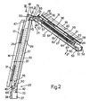
- Segments 18 and 19 may be either rigid or limp; mechanisms 23 and 24 may be located inside or outside conduit 5; and, in the Figure 1 and 2 embodiment, segments 18 and 19 have a rigid, cylindrical wall 20.
- each mechanism 23, 24 comprises a pair of bars 26 and 27 (Figure 2) connected to each other in the form of an articulated parallelogram;
- bar 26 has a U-shaped section with a rib 28 (see also Figure 4) and two parallel wings 29; and rib 28 of bar 26 is fitted to the outside of relative segment 18, 19 by means of at least two fastening elements or brackets 31.
- rib 28 may be pinned, riveted or welded to brackets 31, which in turn are pinned, riveted or welded along the bottom generating line in the vertical diametrical plane of relative segment 18, 19.
- Bar 27 is also U-shaped with a rib 32 and two parallel wings 33 closer together than wings 29; bar 27 is positioned opposite bar 26, with wings 33 inserted between wings 29 to form a substantially closed channel 34; and the two channels 34 of mechanisms 23 and 24 house respective compression springs 35 ( Figure 3) and 36 ( Figure 5) described in detail later on.
- Each mechanism 23, 24 comprises two articulated elements for parallelogram-connecting bars 26 and 27.
- One of the two articulated elements of mechanism 23 ( Figures 1 and 3) comprises a U-shaped section 37 fixed by a bracket 38 to fitting 11, and having two wings 39 (see also Figure 4) spaced so as to fit between wings 29 of bar 26 and wings 33 of bar 27.
- a pin 40 is fitted close to the ends of wings 29 of bar 26 adjacent to section 37, and extends through two spacer washers 41 and two holes formed in wings 39 of section 37, so that bar 26 is connected in articulated manner to section 37.
- a further pin 42 is fitted to wings 39 of section 37, and extends through a further two spacer washers 43 and two holes formed in the ends of wings 33 of bar 27, which is therefore also connected in articulated manner to section 37.
- the second articulated element of mechanism 23 comprises a further U-shaped section 44 (Figure 2) having two wings 45 the same distance apart as the wings of section 37, and which, in the same way as pins 40 and 42, are connected in articulated manner, by means of a further two pins 46 and 47, to the other ends of wings 29 and 33 of bars 26 and 27.
- Pins 40 and 42 are so located that the respective axes lie in a plane P ( Figure 3) inclined, in the example shown, at a 45° angle with respect to axis 14 of fitting 11; and pins 46 and 47 obviously lie in a plane parallel to plane P.
- One of the two articulated elements of mechanism 24 ( Figure 2) comprises the same section 44, the wings 45 of which are connected in articulated manner to the ends of wings 29 and 33 of relative bars 26 and 27 by means of a further two pins 48 and 49, so that section 44 defines an articulated element common to both mechanisms 23 and 24, which are thus self-supporting.
- Pins 46-49 are arranged in the form of a trapezium with the longer side at the top.
- the second articulated element of mechanism 24 comprises a third U-shaped section 51, which, by means of two pins 52 and 53, is only connected in articulated manner to the other ends of wings 29 and 33 of bars 26 and 27.
- the wings 29 of bars 26 of both mechanisms 23 and 24 comprise a cavity 50 to enable bars 26 to rotate with respect to sections 37, 44, 51 without interfering with the ends of respective pins 42, 47, 49, 53.
- a member comprising a piston 57 slides inside the portion of tube 54 adjacent to section 37, 44, and comprises two annular grooves housing two piston rings 58 made of low-friction material for guiding piston 57 smoothly along tube 54.
- Each piston 57 comprises a threaded hole 59 engaged by a threaded end 61 of a rod 62 about which respective spring 35, 36 is wound.
- rod 62 is fitted with a second stop for arresting respective spring 35, 36, and which comprises a flange 64 of a sleeve 66 sliding freely along rod 62. End 63 is also threaded, and is engaged by a nut 67 for locking flange 64 in opposition to the action of spring 35, 36. As shown in Figures 2 and 5, rod 62 may advantageously be threaded along its whole length to integrate both ends 61 and 63.
- Each nut 67 is screwed adjustably to end 63 of rod 62 to adjust the preload of respective spring 35, 36; for which purpose, the rib of section 44 comprises a hole or cavity 68 ( Figure 6) and the rib of section 51 ( Figure 2) comprises a similar cavity enabling access to each nut 67 by a wrench.
- the preload of each spring 35, 36 is adjusted accurately by means of respective nut 67, so as to balance the action of springs 35 and 36 and minimize the effort required on the part of the operator to move hood 7 along the work table.
- each lever member 69 comprises two similar parallel levers 71 ( Figures 4 and 5) pivoting about a pin 72 ( Figure 2) fitted to wings 39 of section 37 in the case of mechanism 23, and about a pin 73 fitted to wings 45 of section 44 in the case of mechanism 24.
- each pair of levers 71 are housed inside two parallel slots 74 ( Figure 5) at the outward end of respective piston 57; the two levers 71 are hinged to said end of piston 57 by means of a further pin 76; and each section 37, 44 comprises a pin 77 ( Figure 3) against which each pair of levers 71 is arrested in the limit position shown in Figures 2 and 3.
- Pins 72 and 73 in respective sections 37 and 44 are located further away from respective second stops 64 than respective pins 40, 42 and 48, 49, and are therefore eccentric with respect to pins 42 and 49 of bars 27. Consequently, when each pair of levers 71 is rotated from the limit position against respective pin 77, respective piston 57 moves closer to disk 55 to reduce the preload of respective spring 35, 36. Disk 55 therefore defines the other limit stop when rotating levers 71, and hence respective mechanism 23, 24, into the bent position shown by the dot-and-dash line in Figure 3 and in Figure 5.
- Conduit 5 as described operates as follows.
- hood 7 angularly about axis 14, by rotating fitting 11 on its bearing, or along the work table, or vertically towards the source of fumes or gas for removal. More specifically, commencing from the Figure 1 and 2 position, hood 7 is moved away from fitting 11 by bending mechanism 23, and hence rigid segment 18 of conduit 5, with respect to section 37 and fitting 11, and is moved towards fitting 11 by bending mechanism 24 with respect to section 44.
- Positioning hood 7, however, normally involves moving it both vertically and radially by rotating one or both of mechanisms 23, 24 with respect to sections 37, 44.
- rotation of mechanism 23 causes common section 44 to move parallel to itself, so that both mechanism 24 and segment 19 also move parallel to themselves; and, similarly, rotation of mechanism 24 with respect to section 44 causes section 51 to move parallel to itself.
- hood 7 is rotated to position the bottom edge of the hood as required with respect to the table of the work station.
- segments 18 and 19 again comprise a rigid wall 20; and mechanisms 23 and 24 are again defined by a pair of U-section bars 26, 27 between which respective spring 35, 36 is inserted (see also Figures 3-5), but in this case are shorter and are not connected directly to each other.
- bar 26 of each mechanism 23, 24 is fitted, e.g. welded or pinned, to an annular bracket 78 in turn fitted in any known manner to the end of the corresponding segment 18, 19; bars 26 and 27 of mechanism 23 are connected in the form of an articulated parallelogram to articulated element 37 and to a second articulated element defined by a further U-shaped section 79; and section 79 is connected by pins 46 and 47 to bars 26 and 27 only, and comprises a hole or cavity similar to that of section 51.
- Bars 26 and 27 of mechanism 24 are connected in the form of an articulated parallelogram to an articulated element defined by a further U-shaped section 81, which is separate from section 79 and is fitted rigidly, e.g. by means of two pins 83, to a further annular bracket 82 fitted in any known mannerto the end of segment 18 adjacent to flexible portion 21; and bars 26 and 27 of mechanism 24 are connected to section 51 in the same way as mechanism 24 in Figure 1.
- section 81 When the Figure 7 segment 18 is rotated together with mechanism 23 with respect to section 37, section 81 also rotates integrally with segment 18, so that segment 19 and mechanism 24 also rotate with respect to section 37.
- Mechanism 24, in turn, may be rotated with respect to section 81 independently of mechanism 23.
- mechanisms 23 and 24 may be housed inside segments 18 and 19 and protected by sealing rings to prevent dust or suspended particles in the fumes from settling inside the mechanisms. If defined by a limp wall, segments 18 and 19 in Figure 1 are supported by mechanisms 23 and 24, which are self-supporting, and segments 18 and 19 in Figure 7 may be supported by any known type of supporting structure, possibly inside the segments.
- channel 34 of each mechanism 23, 24 provides for fully protecting both tube 54 and respective balancing spring 35, 36; and the articulated parallelogram connection of bars 26 and 27 provides for stable rotation of mechanisms 23 and 24.
- rod 62 and nut 67 provide for accurately adjusting the preload of each spring 35, 36 to achieve the best balance; and the connection of rod 62 to levers 71 provides for varying the preload of spring 35, 36 as a function of the bend angle of mechanism 23, 24 with respect to the corresponding articulated element 37,44,81.
- rod 62 may be threaded at ends 61 and 63 only, as opposed to along its whole length; the angle of plane P with respect to axis 14 may vary according to the type of application; disk 55 may be welded to tube 54 as opposed to using a pin or screw; and flange 64 may be dispensed with, and the spring 35, 36 stop defined by nut 67 itself.
- bars 26 and 27 may have a curved as opposed to a U-shaped section; lever member 69 may be defined by only one lever 71 and/or the wings of one or more of sections 37, 44, 51, 79, 81 may be located outwards of those of bars 26; and fitting 11 may be ceiling-mounted, may be fitted to a support at a higher level than the work station, and may be connected to a centralized suction system as opposed to directly to a single aspirator.
Abstract
Description
Claims (24)
- An all-purpose conduit for conveying harmful fumes or gases away from a work station, and comprising a fitting (11) for connection to a flexible conduit portion (12), said fitting (11) rotating about its own axis (14); at least one conduit segment (18) connected to said flexible conduit portion (12); an articulated mechanism (23) for varying the angular position of said conduit segment (18) with respect to said fitting (11); and balancing spring means (35) between said fitting (11) and said articulated mechanism (23), characterized in that said articulated mechanism (23) comprises a pair of bars (26, 27) connected to each other in form of an articulated parallelogram by means of a pair of articulated elements (37, 44; 37, 79); said pair of bars (26, 27) forming a substantially closed channel (34); a first one (37) of said articulated elements (37, 44; 37, 79) being fixed to said fitting (11); said spring means including a spiral compression spring (35) inserted inside a rigid tube (54), which is housed in said channel (34) and fitted to one of said bars (26, 27); said compression spring (35) being compressed between a first stop (55) fixed to said tube (54) and a second stop (64) connected to a lever member (69), which is hinged to said first articulated element (37) in such a manner that the action of said compression spring (35) is varied according to the angular position of said segment (18) with respect to said fitting (11).
- A conduit as claimed in Claim 1, characterized In that said conduit segment (18) may be rigid or limp; and said articulated mechanism (23) is located inside or outside said conduit segment (18).
- A conduit as claimed in Claim 1 or 2, characterized in that said pair of bars (26, 27) comprises a first bar (26) having a U-shaped section and the rib (28) of which is fitted to the outside of said conduit segment (18), and a second bar (27) having a U-shaped section and located opposite said first bar (26); the wings (33) of said second bar (27) being inserted between the wings (29) of said first bar (26) to form said channel (34), said rigid tube (54) being fitted to the wings (33) of said second bar (27).
- A conduit as claimed in Claim 1, characterized in that said second stop (64) is fitted to a rod (62) inserted inside said spring (35); a sliding member (57) inside said tube (54) being fitted to said rod (62) and being hinged to said lever member (69).
- A conduit as claimed in Claim 4, characterized in that said rod (62) comprises at least one threaded portion (63) to which is screwed a nut (67) for locking said second stop (64) and adjusting the preload of said spring (35).
- A conduit as claimed in one of the foregoing Claims from 1 to 5, characterized in that said lever member(69) pivots about a pin (72) so located as to vary the preload of said spring (35) as a function of the rotation of said mechanism (23) with respect to said first articulated element (37).
- A conduit as claimed in Claim 6, characterized in that said bars (26, 27) are hinged to said first articulated element (37) by means of two respective pins (40, 42); the pin (72) of said lever member (69) being located further away from said second stop (64) than each of said respective pins (40, 42).
- A conduit as claimed in one of the foregoing Claims from 5 to 7, characterized in that said first stop comprises a disk (55) having a hole and fixed inside said tube (54); said second stop comprising a flange (64) sliding along said rod (62) and pushed by said spring (35) against said nut (67).
- A conduit as claimed in Claim 8, characterized in that said sliding member comprises a piston (57) having at least two piston rings (58) made of low-friction material and for guiding the piston along the inner surface of said tube (54); said rod (62) having a second threaded portion (61) engaging a threaded hole (59) in said piston (57).
- A conduit as claimed in Claim 9, characterized in that said piston (57) is arrested against said disk (55) to define one end of the travel of said lever member (69); said first articulated element (37) comprising a stop (77) defining another end of the travel of said lever member (69).
- A conduit as claimed in Claim 10, characterized in that said piston (57) terminates outwards of said tube (54) with a pair of slots (74); said lever member (69) comprising two similar parallel levers (71) Inserted inside said slots (74); and a through pin (76), perpendicular to said slots (74), being provided to connect said levers (71) in articulated manner to said piston (57).
- A conduit as claimed in one of the foregoing Claims from 3 to 11, characterized in that each of said articulated elements (37, 44, 79) comprises a U-shaped section, the wings (39, 45, 77) of which are inserted between the wings (29, 33) of said first and said second bar (26, 27); the U-shaped section of said first articulated element (37) being fixed to said fitting (11) by a bracket (38) fixed to the outside of said fitting (11).
- A conduit as claimed in Claim 12, characterized in that the U-shaped section of said second articulated element (44, 79) comprises a cavity (68) permitting adjustment of said nut (67) on said rod (62).
- A conduit as claimed in Claim 12 or 13, wherein the section of the fume passage is circular, characterized in that said conduit segment (18) comprises a rigid, cylindrical wall (20); said first bar (26) being fixed to the outside of said conduit segment (18) by means of at least two elements (31) fixed along a generating line of said wall (20).
- A conduit as claimed in Claim 12 or 13, wherein the section of the fume passage is circular, characterized in that said at least one conduit segment forme a first conduit segment (18) comprising a rigid, cylindrical wall (20); said first bar (26) being fixed to the outside of said first conduit segment (18), along a generating line of said wall (20), by means of an annular bracket (78) surrounding said wall (20).
- A conduit as claimed in one of the foregoing Claims, characterized in that said first conduit segment (18) is connected by a second flexible conduit portion (21) to a second conduit segment (19); said second conduit segment (19) being provided with a second articulated mechanism (24); and said two articulated mechanisms (23, 24) being similar.
- A conduit as claimed in Claims 12 and 16, characterized in that the pair of bars (26, 27) of said second mechanism (24) is connected in the form of an articulated parallelogram to a first and a second articulated element (44, 81; 51); said second articulated element (51) comprising a cavity permitting adjustment of the respective nut (67) on the corresponding rod (62).
- A conduit as claimed in Claims 14 and 16, characterized in that said two articulated mechanisms (23, 24) have a common articulated element (44); the first bar (26) of said second mechanism (24) beIng fixed to said second conduit segment (19) by means of a corresponding pair of elements (31); and the other articulated element (51) of said second articulated mechanism (24) being connected to the relative pair of bars (26, 27) only.
- A conduit as claimed in Claim 18, characterized in that the axes of said respective pins (40, 42) of said first articulated element (37) lie in a plane (P) at a substantially 45° angle with respect to the axis (14) of said fitting (11); the pins (46-49) of the pairs of bars (26, 27) of said articulated mechanisms (23, 24) being arranged in the form of a trapezium, so as to keep said two conduit segments (18,19) at an angle with respect to each other.
- A conduit as claimed in Claims 15 and 16, characterized in that said articulated mechanisms (23, 24) are independent of each other; the first bar (26) of said second mechanism (24) being fixed to said second conduit segment (19) by means of a respective bracket (78) surrounding the respective cylindrical wall (20).
- A conduit as claimed in Claim 20, characterized in that the first articulated element (81) of said second mechanism (24) is fitted to a bracket (82) fitted to one end of said first conduit segment (18); the second articulated element (79, 51) of each of said mechanisms (23, 24) being connected to the respective two bars (26, 27) only.
- A conduit as claimed in one of the foregoing Claims from 16 to 21, characterized in that said second conduit segment (19) is connected to a fume or gas conveying element (7) by means of a third flexible conduit portion (16).
- A conduit as claimed in one of the foregoing Claims, characterized in that said fitting (11) is connected to an aspirator (6) fitted to a fixed or movable support (8) substantially on a level with or at a lower level than the work station.
- A conduit as claimed in one of the foregoing Claims from 1 to 22, characterized in that said fitting (11) is ceiling-mounted or fitted to a support at a higher level than said work station.
Applications Claiming Priority (3)
| Application Number | Priority Date | Filing Date | Title |
|---|---|---|---|
| IT97TO000178A IT1291164B1 (en) | 1997-03-04 | 1997-03-04 | UNIVERSAL DUCT FOR THE CONVEYANCE OF HARMFUL SMOKES OR GAS FROM A WORKING PLACE. |
| ITTO970178 | 1997-03-04 | ||
| PCT/IT1997/000289 WO1998039112A1 (en) | 1997-03-04 | 1997-11-20 | All-purpose conduit for conveying harmful fumes or gases away from a work station |
Publications (3)
| Publication Number | Publication Date |
|---|---|
| EP1015140A1 EP1015140A1 (en) | 2000-07-05 |
| EP1015140B1 EP1015140B1 (en) | 2001-11-07 |
| EP1015140B2 true EP1015140B2 (en) | 2005-12-07 |
Family
ID=11415469
Family Applications (1)
| Application Number | Title | Priority Date | Filing Date |
|---|---|---|---|
| EP97946049A Expired - Lifetime EP1015140B2 (en) | 1997-03-04 | 1997-11-20 | All-purpose conduit for conveying harmful fumes or gases away from a work station |
Country Status (11)
| Country | Link |
|---|---|
| US (2) | US6413158B1 (en) |
| EP (1) | EP1015140B2 (en) |
| AT (1) | ATE208238T1 (en) |
| AU (1) | AU5134798A (en) |
| CA (1) | CA2281558C (en) |
| DE (1) | DE69708162T3 (en) |
| DK (1) | DK1015140T4 (en) |
| ES (1) | ES2163199T5 (en) |
| IT (1) | IT1291164B1 (en) |
| PT (1) | PT1015140E (en) |
| WO (1) | WO1998039112A1 (en) |
Families Citing this family (416)
| Publication number | Priority date | Publication date | Assignee | Title |
|---|---|---|---|---|
| ITTO20020437A1 (en) | 2002-05-23 | 2003-11-24 | Coral Spa | BALANCING DEVICE OF A LEFT ARM ON A ROTATION AXIS, FOR EXAMPLE FOR A UNIVERSAL FUME OR GAS DUCT FROM A PLACE |
| US20070084897A1 (en) | 2003-05-20 | 2007-04-19 | Shelton Frederick E Iv | Articulating surgical stapling instrument incorporating a two-piece e-beam firing mechanism |
| US9060770B2 (en) | 2003-05-20 | 2015-06-23 | Ethicon Endo-Surgery, Inc. | Robotically-driven surgical instrument with E-beam driver |
| US20050161945A1 (en) * | 2004-01-23 | 2005-07-28 | San Ford Machinery Co., Ltd. | Cantilever wind-exhausting pipe |
| ITMI20040380A1 (en) * | 2004-03-02 | 2004-06-02 | Airbox Srl | PANTOGRAPH SUCTION ARM WITH VARIABLE ANCHORAGE OF THE BALANCING SPRINGS |
| US11896225B2 (en) | 2004-07-28 | 2024-02-13 | Cilag Gmbh International | Staple cartridge comprising a pan |
| US8215531B2 (en) | 2004-07-28 | 2012-07-10 | Ethicon Endo-Surgery, Inc. | Surgical stapling instrument having a medical substance dispenser |
| US11484312B2 (en) | 2005-08-31 | 2022-11-01 | Cilag Gmbh International | Staple cartridge comprising a staple driver arrangement |
| US7669746B2 (en) | 2005-08-31 | 2010-03-02 | Ethicon Endo-Surgery, Inc. | Staple cartridges for forming staples having differing formed staple heights |
| US10159482B2 (en) | 2005-08-31 | 2018-12-25 | Ethicon Llc | Fastener cartridge assembly comprising a fixed anvil and different staple heights |
| US11246590B2 (en) | 2005-08-31 | 2022-02-15 | Cilag Gmbh International | Staple cartridge including staple drivers having different unfired heights |
| US9237891B2 (en) | 2005-08-31 | 2016-01-19 | Ethicon Endo-Surgery, Inc. | Robotically-controlled surgical stapling devices that produce formed staples having different lengths |
| US7934630B2 (en) | 2005-08-31 | 2011-05-03 | Ethicon Endo-Surgery, Inc. | Staple cartridges for forming staples having differing formed staple heights |
| SE529098C2 (en) * | 2005-09-09 | 2007-05-02 | P H Nederman & Co Ab | Extraction hood and method of assembling the same |
| US7673780B2 (en) * | 2005-11-09 | 2010-03-09 | Ethicon Endo-Surgery, Inc. | Articulation joint with improved moment arm extension for articulating an end effector of a surgical instrument |
| US20070106317A1 (en) | 2005-11-09 | 2007-05-10 | Shelton Frederick E Iv | Hydraulically and electrically actuated articulation joints for surgical instruments |
| US11278279B2 (en) | 2006-01-31 | 2022-03-22 | Cilag Gmbh International | Surgical instrument assembly |
| US20110024477A1 (en) | 2009-02-06 | 2011-02-03 | Hall Steven G | Driven Surgical Stapler Improvements |
| US11224427B2 (en) | 2006-01-31 | 2022-01-18 | Cilag Gmbh International | Surgical stapling system including a console and retraction assembly |
| US8708213B2 (en) | 2006-01-31 | 2014-04-29 | Ethicon Endo-Surgery, Inc. | Surgical instrument having a feedback system |
| US8186555B2 (en) | 2006-01-31 | 2012-05-29 | Ethicon Endo-Surgery, Inc. | Motor-driven surgical cutting and fastening instrument with mechanical closure system |
| US11793518B2 (en) | 2006-01-31 | 2023-10-24 | Cilag Gmbh International | Powered surgical instruments with firing system lockout arrangements |
| US8820603B2 (en) | 2006-01-31 | 2014-09-02 | Ethicon Endo-Surgery, Inc. | Accessing data stored in a memory of a surgical instrument |
| US20110295295A1 (en) | 2006-01-31 | 2011-12-01 | Ethicon Endo-Surgery, Inc. | Robotically-controlled surgical instrument having recording capabilities |
| US20120292367A1 (en) | 2006-01-31 | 2012-11-22 | Ethicon Endo-Surgery, Inc. | Robotically-controlled end effector |
| US7753904B2 (en) | 2006-01-31 | 2010-07-13 | Ethicon Endo-Surgery, Inc. | Endoscopic surgical instrument with a handle that can articulate with respect to the shaft |
| US7845537B2 (en) | 2006-01-31 | 2010-12-07 | Ethicon Endo-Surgery, Inc. | Surgical instrument having recording capabilities |
| US8992422B2 (en) | 2006-03-23 | 2015-03-31 | Ethicon Endo-Surgery, Inc. | Robotically-controlled endoscopic accessory channel |
| US8322455B2 (en) | 2006-06-27 | 2012-12-04 | Ethicon Endo-Surgery, Inc. | Manually driven surgical cutting and fastening instrument |
| WO2008030233A1 (en) * | 2006-09-05 | 2008-03-13 | Saari Dean T | Chip vacuum system and apparatus |
| US10568652B2 (en) | 2006-09-29 | 2020-02-25 | Ethicon Llc | Surgical staples having attached drivers of different heights and stapling instruments for deploying the same |
| US8220690B2 (en) | 2006-09-29 | 2012-07-17 | Ethicon Endo-Surgery, Inc. | Connected surgical staples and stapling instruments for deploying the same |
| US7434771B1 (en) * | 2006-11-14 | 2008-10-14 | Double Color Industrial Ltd. | Expandable support for sewer or drainage conduit |
| US8652120B2 (en) | 2007-01-10 | 2014-02-18 | Ethicon Endo-Surgery, Inc. | Surgical instrument with wireless communication between control unit and sensor transponders |
| US8684253B2 (en) | 2007-01-10 | 2014-04-01 | Ethicon Endo-Surgery, Inc. | Surgical instrument with wireless communication between a control unit of a robotic system and remote sensor |
| US11291441B2 (en) | 2007-01-10 | 2022-04-05 | Cilag Gmbh International | Surgical instrument with wireless communication between control unit and remote sensor |
| US11039836B2 (en) | 2007-01-11 | 2021-06-22 | Cilag Gmbh International | Staple cartridge for use with a surgical stapling instrument |
| US8827133B2 (en) | 2007-01-11 | 2014-09-09 | Ethicon Endo-Surgery, Inc. | Surgical stapling device having supports for a flexible drive mechanism |
| US7669747B2 (en) | 2007-03-15 | 2010-03-02 | Ethicon Endo-Surgery, Inc. | Washer for use with a surgical stapling instrument |
| US8893946B2 (en) | 2007-03-28 | 2014-11-25 | Ethicon Endo-Surgery, Inc. | Laparoscopic tissue thickness and clamp load measuring devices |
| US8931682B2 (en) | 2007-06-04 | 2015-01-13 | Ethicon Endo-Surgery, Inc. | Robotically-controlled shaft based rotary drive systems for surgical instruments |
| US11857181B2 (en) | 2007-06-04 | 2024-01-02 | Cilag Gmbh International | Robotically-controlled shaft based rotary drive systems for surgical instruments |
| US7753245B2 (en) | 2007-06-22 | 2010-07-13 | Ethicon Endo-Surgery, Inc. | Surgical stapling instruments |
| US11849941B2 (en) | 2007-06-29 | 2023-12-26 | Cilag Gmbh International | Staple cartridge having staple cavities extending at a transverse angle relative to a longitudinal cartridge axis |
| US7819298B2 (en) | 2008-02-14 | 2010-10-26 | Ethicon Endo-Surgery, Inc. | Surgical stapling apparatus with control features operable with one hand |
| US7866527B2 (en) | 2008-02-14 | 2011-01-11 | Ethicon Endo-Surgery, Inc. | Surgical stapling apparatus with interlockable firing system |
| US8573465B2 (en) | 2008-02-14 | 2013-11-05 | Ethicon Endo-Surgery, Inc. | Robotically-controlled surgical end effector system with rotary actuated closure systems |
| BRPI0901282A2 (en) | 2008-02-14 | 2009-11-17 | Ethicon Endo Surgery Inc | surgical cutting and fixation instrument with rf electrodes |
| US8758391B2 (en) | 2008-02-14 | 2014-06-24 | Ethicon Endo-Surgery, Inc. | Interchangeable tools for surgical instruments |
| US8636736B2 (en) | 2008-02-14 | 2014-01-28 | Ethicon Endo-Surgery, Inc. | Motorized surgical cutting and fastening instrument |
| US9179912B2 (en) | 2008-02-14 | 2015-11-10 | Ethicon Endo-Surgery, Inc. | Robotically-controlled motorized surgical cutting and fastening instrument |
| US11272927B2 (en) | 2008-02-15 | 2022-03-15 | Cilag Gmbh International | Layer arrangements for surgical staple cartridges |
| US9770245B2 (en) | 2008-02-15 | 2017-09-26 | Ethicon Llc | Layer arrangements for surgical staple cartridges |
| US11648005B2 (en) | 2008-09-23 | 2023-05-16 | Cilag Gmbh International | Robotically-controlled motorized surgical instrument with an end effector |
| US8210411B2 (en) | 2008-09-23 | 2012-07-03 | Ethicon Endo-Surgery, Inc. | Motor-driven surgical cutting instrument |
| US9386983B2 (en) | 2008-09-23 | 2016-07-12 | Ethicon Endo-Surgery, Llc | Robotically-controlled motorized surgical instrument |
| US9005230B2 (en) | 2008-09-23 | 2015-04-14 | Ethicon Endo-Surgery, Inc. | Motorized surgical instrument |
| US8608045B2 (en) | 2008-10-10 | 2013-12-17 | Ethicon Endo-Sugery, Inc. | Powered surgical cutting and stapling apparatus with manually retractable firing system |
| US8517239B2 (en) | 2009-02-05 | 2013-08-27 | Ethicon Endo-Surgery, Inc. | Surgical stapling instrument comprising a magnetic element driver |
| US8444036B2 (en) | 2009-02-06 | 2013-05-21 | Ethicon Endo-Surgery, Inc. | Motor driven surgical fastener device with mechanisms for adjusting a tissue gap within the end effector |
| CA2751664A1 (en) | 2009-02-06 | 2010-08-12 | Ethicon Endo-Surgery, Inc. | Driven surgical stapler improvements |
| EP2454031A4 (en) * | 2009-07-17 | 2014-08-20 | Diversitech Equipment And Sales 1984 Ltd | Fume extraction system with automatic fume hood positioning |
| US8851354B2 (en) | 2009-12-24 | 2014-10-07 | Ethicon Endo-Surgery, Inc. | Surgical cutting instrument that analyzes tissue thickness |
| US8220688B2 (en) | 2009-12-24 | 2012-07-17 | Ethicon Endo-Surgery, Inc. | Motor-driven surgical cutting instrument with electric actuator directional control assembly |
| US8783543B2 (en) | 2010-07-30 | 2014-07-22 | Ethicon Endo-Surgery, Inc. | Tissue acquisition arrangements and methods for surgical stapling devices |
| US9629814B2 (en) | 2010-09-30 | 2017-04-25 | Ethicon Endo-Surgery, Llc | Tissue thickness compensator configured to redistribute compressive forces |
| US9364233B2 (en) | 2010-09-30 | 2016-06-14 | Ethicon Endo-Surgery, Llc | Tissue thickness compensators for circular surgical staplers |
| US11849952B2 (en) | 2010-09-30 | 2023-12-26 | Cilag Gmbh International | Staple cartridge comprising staples positioned within a compressible portion thereof |
| US9592050B2 (en) | 2010-09-30 | 2017-03-14 | Ethicon Endo-Surgery, Llc | End effector comprising a distal tissue abutment member |
| US9320523B2 (en) | 2012-03-28 | 2016-04-26 | Ethicon Endo-Surgery, Llc | Tissue thickness compensator comprising tissue ingrowth features |
| US9351730B2 (en) | 2011-04-29 | 2016-05-31 | Ethicon Endo-Surgery, Llc | Tissue thickness compensator comprising channels |
| US11812965B2 (en) | 2010-09-30 | 2023-11-14 | Cilag Gmbh International | Layer of material for a surgical end effector |
| US10945731B2 (en) | 2010-09-30 | 2021-03-16 | Ethicon Llc | Tissue thickness compensator comprising controlled release and expansion |
| US8978954B2 (en) | 2010-09-30 | 2015-03-17 | Ethicon Endo-Surgery, Inc. | Staple cartridge comprising an adjustable distal portion |
| US11298125B2 (en) | 2010-09-30 | 2022-04-12 | Cilag Gmbh International | Tissue stapler having a thickness compensator |
| US9517063B2 (en) | 2012-03-28 | 2016-12-13 | Ethicon Endo-Surgery, Llc | Movable member for use with a tissue thickness compensator |
| US8695866B2 (en) | 2010-10-01 | 2014-04-15 | Ethicon Endo-Surgery, Inc. | Surgical instrument having a power control circuit |
| US9623506B2 (en) | 2011-02-01 | 2017-04-18 | Illinois Tool Works Inc. | Fume extractor for welding applications |
| CA2834649C (en) | 2011-04-29 | 2021-02-16 | Ethicon Endo-Surgery, Inc. | Staple cartridge comprising staples positioned within a compressible portion thereof |
| US11207064B2 (en) | 2011-05-27 | 2021-12-28 | Cilag Gmbh International | Automated end effector component reloading system for use with a robotic system |
| US9072535B2 (en) | 2011-05-27 | 2015-07-07 | Ethicon Endo-Surgery, Inc. | Surgical stapling instruments with rotatable staple deployment arrangements |
| US9821351B2 (en) | 2011-11-11 | 2017-11-21 | Illinois Tool Works Inc. | Welding fume extractor |
| US9044230B2 (en) | 2012-02-13 | 2015-06-02 | Ethicon Endo-Surgery, Inc. | Surgical cutting and fastening instrument with apparatus for determining cartridge and firing motion status |
| US9498805B2 (en) * | 2012-03-16 | 2016-11-22 | Illinois Tool Works Inc. | Airborne component extractor with improved flow paths |
| JP6224070B2 (en) | 2012-03-28 | 2017-11-01 | エシコン・エンド−サージェリィ・インコーポレイテッドEthicon Endo−Surgery,Inc. | Retainer assembly including tissue thickness compensator |
| CN104334098B (en) | 2012-03-28 | 2017-03-22 | 伊西康内外科公司 | Tissue thickness compensator comprising capsules defining a low pressure environment |
| JP6305979B2 (en) | 2012-03-28 | 2018-04-04 | エシコン・エンド−サージェリィ・インコーポレイテッドEthicon Endo−Surgery,Inc. | Tissue thickness compensator with multiple layers |
| US9101358B2 (en) | 2012-06-15 | 2015-08-11 | Ethicon Endo-Surgery, Inc. | Articulatable surgical instrument comprising a firing drive |
| US20140005718A1 (en) | 2012-06-28 | 2014-01-02 | Ethicon Endo-Surgery, Inc. | Multi-functional powered surgical device with external dissection features |
| US11278284B2 (en) | 2012-06-28 | 2022-03-22 | Cilag Gmbh International | Rotary drive arrangements for surgical instruments |
| CN104487005B (en) | 2012-06-28 | 2017-09-08 | 伊西康内外科公司 | Empty squeeze latching member |
| BR112014032776B1 (en) | 2012-06-28 | 2021-09-08 | Ethicon Endo-Surgery, Inc | SURGICAL INSTRUMENT SYSTEM AND SURGICAL KIT FOR USE WITH A SURGICAL INSTRUMENT SYSTEM |
| US20140001231A1 (en) | 2012-06-28 | 2014-01-02 | Ethicon Endo-Surgery, Inc. | Firing system lockout arrangements for surgical instruments |
| US9289256B2 (en) | 2012-06-28 | 2016-03-22 | Ethicon Endo-Surgery, Llc | Surgical end effectors having angled tissue-contacting surfaces |
| US9649111B2 (en) | 2012-06-28 | 2017-05-16 | Ethicon Endo-Surgery, Llc | Replaceable clip cartridge for a clip applier |
| US20140001234A1 (en) | 2012-06-28 | 2014-01-02 | Ethicon Endo-Surgery, Inc. | Coupling arrangements for attaching surgical end effectors to drive systems therefor |
| US9839948B2 (en) | 2013-01-29 | 2017-12-12 | Illinois Tool Works Inc. | Fume evacuation system |
| MX364729B (en) | 2013-03-01 | 2019-05-06 | Ethicon Endo Surgery Inc | Surgical instrument with a soft stop. |
| MX368026B (en) | 2013-03-01 | 2019-09-12 | Ethicon Endo Surgery Inc | Articulatable surgical instruments with conductive pathways for signal communication. |
| US9629629B2 (en) | 2013-03-14 | 2017-04-25 | Ethicon Endo-Surgey, LLC | Control systems for surgical instruments |
| US9629623B2 (en) | 2013-03-14 | 2017-04-25 | Ethicon Endo-Surgery, Llc | Drive system lockout arrangements for modular surgical instruments |
| US10405857B2 (en) | 2013-04-16 | 2019-09-10 | Ethicon Llc | Powered linear surgical stapler |
| BR112015026109B1 (en) | 2013-04-16 | 2022-02-22 | Ethicon Endo-Surgery, Inc | surgical instrument |
| US9046193B1 (en) * | 2013-04-18 | 2015-06-02 | Sam Carbis Asset Management, Llc | Self-supporting, flexible support for flexible hose that transports product from bulk transport tank |
| US10808953B2 (en) | 2013-06-28 | 2020-10-20 | Illinois Tool Works Inc. | Airborne component extractor with baffled debris collection |
| CN106028966B (en) | 2013-08-23 | 2018-06-22 | 伊西康内外科有限责任公司 | For the firing member restoring device of powered surgical instrument |
| US9808249B2 (en) | 2013-08-23 | 2017-11-07 | Ethicon Llc | Attachment portions for surgical instrument assemblies |
| ITMO20130347A1 (en) * | 2013-12-17 | 2015-06-18 | Cnh Italia Spa | AIR INTAKE DUCT FOR AN INTERNAL COMBUSTION ENGINE OF AN AGRICULTURAL VEHICLE. |
| US9962161B2 (en) | 2014-02-12 | 2018-05-08 | Ethicon Llc | Deliverable surgical instrument |
| JP6462004B2 (en) | 2014-02-24 | 2019-01-30 | エシコン エルエルシー | Fastening system with launcher lockout |
| BR112016021943B1 (en) | 2014-03-26 | 2022-06-14 | Ethicon Endo-Surgery, Llc | SURGICAL INSTRUMENT FOR USE BY AN OPERATOR IN A SURGICAL PROCEDURE |
| US9733663B2 (en) | 2014-03-26 | 2017-08-15 | Ethicon Llc | Power management through segmented circuit and variable voltage protection |
| US9750499B2 (en) | 2014-03-26 | 2017-09-05 | Ethicon Llc | Surgical stapling instrument system |
| US9820738B2 (en) | 2014-03-26 | 2017-11-21 | Ethicon Llc | Surgical instrument comprising interactive systems |
| CN106456176B (en) | 2014-04-16 | 2019-06-28 | 伊西康内外科有限责任公司 | Fastener cartridge including the extension with various configuration |
| BR112016023807B1 (en) | 2014-04-16 | 2022-07-12 | Ethicon Endo-Surgery, Llc | CARTRIDGE SET OF FASTENERS FOR USE WITH A SURGICAL INSTRUMENT |
| US9801627B2 (en) | 2014-09-26 | 2017-10-31 | Ethicon Llc | Fastener cartridge for creating a flexible staple line |
| US20150297225A1 (en) | 2014-04-16 | 2015-10-22 | Ethicon Endo-Surgery, Inc. | Fastener cartridges including extensions having different configurations |
| US10299792B2 (en) | 2014-04-16 | 2019-05-28 | Ethicon Llc | Fastener cartridge comprising non-uniform fasteners |
| BR112016023825B1 (en) | 2014-04-16 | 2022-08-02 | Ethicon Endo-Surgery, Llc | STAPLE CARTRIDGE FOR USE WITH A SURGICAL STAPLER AND STAPLE CARTRIDGE FOR USE WITH A SURGICAL INSTRUMENT |
| US11311294B2 (en) | 2014-09-05 | 2022-04-26 | Cilag Gmbh International | Powered medical device including measurement of closure state of jaws |
| BR112017004361B1 (en) | 2014-09-05 | 2023-04-11 | Ethicon Llc | ELECTRONIC SYSTEM FOR A SURGICAL INSTRUMENT |
| US10135242B2 (en) | 2014-09-05 | 2018-11-20 | Ethicon Llc | Smart cartridge wake up operation and data retention |
| US10105142B2 (en) | 2014-09-18 | 2018-10-23 | Ethicon Llc | Surgical stapler with plurality of cutting elements |
| US11523821B2 (en) | 2014-09-26 | 2022-12-13 | Cilag Gmbh International | Method for creating a flexible staple line |
| CN107427300B (en) | 2014-09-26 | 2020-12-04 | 伊西康有限责任公司 | Surgical suture buttress and buttress material |
| US10076325B2 (en) | 2014-10-13 | 2018-09-18 | Ethicon Llc | Surgical stapling apparatus comprising a tissue stop |
| US9924944B2 (en) | 2014-10-16 | 2018-03-27 | Ethicon Llc | Staple cartridge comprising an adjunct material |
| US11141153B2 (en) | 2014-10-29 | 2021-10-12 | Cilag Gmbh International | Staple cartridges comprising driver arrangements |
| US10517594B2 (en) | 2014-10-29 | 2019-12-31 | Ethicon Llc | Cartridge assemblies for surgical staplers |
| US9844376B2 (en) | 2014-11-06 | 2017-12-19 | Ethicon Llc | Staple cartridge comprising a releasable adjunct material |
| US10242317B2 (en) | 2014-11-25 | 2019-03-26 | Illinois Tool Works Inc. | System for estimating the amount and content of fumes |
| US10736636B2 (en) | 2014-12-10 | 2020-08-11 | Ethicon Llc | Articulatable surgical instrument system |
| BR112017012996B1 (en) | 2014-12-18 | 2022-11-08 | Ethicon Llc | SURGICAL INSTRUMENT WITH AN ANvil WHICH IS SELECTIVELY MOVABLE ABOUT AN IMMOVABLE GEOMETRIC AXIS DIFFERENT FROM A STAPLE CARTRIDGE |
| US9968355B2 (en) | 2014-12-18 | 2018-05-15 | Ethicon Llc | Surgical instruments with articulatable end effectors and improved firing beam support arrangements |
| US10085748B2 (en) | 2014-12-18 | 2018-10-02 | Ethicon Llc | Locking arrangements for detachable shaft assemblies with articulatable surgical end effectors |
| US9844374B2 (en) | 2014-12-18 | 2017-12-19 | Ethicon Llc | Surgical instrument systems comprising an articulatable end effector and means for adjusting the firing stroke of a firing member |
| US9844375B2 (en) | 2014-12-18 | 2017-12-19 | Ethicon Llc | Drive arrangements for articulatable surgical instruments |
| US10188385B2 (en) | 2014-12-18 | 2019-01-29 | Ethicon Llc | Surgical instrument system comprising lockable systems |
| US9987000B2 (en) | 2014-12-18 | 2018-06-05 | Ethicon Llc | Surgical instrument assembly comprising a flexible articulation system |
| US10180463B2 (en) | 2015-02-27 | 2019-01-15 | Ethicon Llc | Surgical apparatus configured to assess whether a performance parameter of the surgical apparatus is within an acceptable performance band |
| US11154301B2 (en) | 2015-02-27 | 2021-10-26 | Cilag Gmbh International | Modular stapling assembly |
| US10321907B2 (en) | 2015-02-27 | 2019-06-18 | Ethicon Llc | System for monitoring whether a surgical instrument needs to be serviced |
| JP2020121162A (en) | 2015-03-06 | 2020-08-13 | エシコン エルエルシーEthicon LLC | Time dependent evaluation of sensor data to determine stability element, creep element and viscoelastic element of measurement |
| US10617412B2 (en) | 2015-03-06 | 2020-04-14 | Ethicon Llc | System for detecting the mis-insertion of a staple cartridge into a surgical stapler |
| US10441279B2 (en) | 2015-03-06 | 2019-10-15 | Ethicon Llc | Multiple level thresholds to modify operation of powered surgical instruments |
| US10548504B2 (en) | 2015-03-06 | 2020-02-04 | Ethicon Llc | Overlaid multi sensor radio frequency (RF) electrode system to measure tissue compression |
| US10245033B2 (en) | 2015-03-06 | 2019-04-02 | Ethicon Llc | Surgical instrument comprising a lockable battery housing |
| US9808246B2 (en) | 2015-03-06 | 2017-11-07 | Ethicon Endo-Surgery, Llc | Method of operating a powered surgical instrument |
| US10687806B2 (en) | 2015-03-06 | 2020-06-23 | Ethicon Llc | Adaptive tissue compression techniques to adjust closure rates for multiple tissue types |
| US9924961B2 (en) | 2015-03-06 | 2018-03-27 | Ethicon Endo-Surgery, Llc | Interactive feedback system for powered surgical instruments |
| US9993248B2 (en) | 2015-03-06 | 2018-06-12 | Ethicon Endo-Surgery, Llc | Smart sensors with local signal processing |
| US9901342B2 (en) | 2015-03-06 | 2018-02-27 | Ethicon Endo-Surgery, Llc | Signal and power communication system positioned on a rotatable shaft |
| US10054338B2 (en) * | 2015-03-19 | 2018-08-21 | Hamilton Sundstrand Corporation | Flexible coupling with rotational capability |
| US10390825B2 (en) | 2015-03-31 | 2019-08-27 | Ethicon Llc | Surgical instrument with progressive rotary drive systems |
| CN104976649B (en) * | 2015-06-15 | 2018-06-15 | 浙江亿田智能厨电股份有限公司 | A kind of integrated kitchen range of the anti-ease smoke evacuation tube connector of band |
| US11014132B2 (en) | 2015-07-16 | 2021-05-25 | Illinois Tool Works Inc. | Extractor with end-mounted positive pressure system |
| US11530826B2 (en) | 2015-07-16 | 2022-12-20 | Illinois Tool Works Inc. | Extractor with segmented positive pressure airflow system |
| US10617418B2 (en) | 2015-08-17 | 2020-04-14 | Ethicon Llc | Implantable layers for a surgical instrument |
| US10327769B2 (en) | 2015-09-23 | 2019-06-25 | Ethicon Llc | Surgical stapler having motor control based on a drive system component |
| US10238386B2 (en) | 2015-09-23 | 2019-03-26 | Ethicon Llc | Surgical stapler having motor control based on an electrical parameter related to a motor current |
| US10105139B2 (en) | 2015-09-23 | 2018-10-23 | Ethicon Llc | Surgical stapler having downstream current-based motor control |
| US10363036B2 (en) | 2015-09-23 | 2019-07-30 | Ethicon Llc | Surgical stapler having force-based motor control |
| US10299878B2 (en) | 2015-09-25 | 2019-05-28 | Ethicon Llc | Implantable adjunct systems for determining adjunct skew |
| US10524788B2 (en) | 2015-09-30 | 2020-01-07 | Ethicon Llc | Compressible adjunct with attachment regions |
| US10271849B2 (en) | 2015-09-30 | 2019-04-30 | Ethicon Llc | Woven constructs with interlocked standing fibers |
| US10980539B2 (en) | 2015-09-30 | 2021-04-20 | Ethicon Llc | Implantable adjunct comprising bonded layers |
| US11890015B2 (en) | 2015-09-30 | 2024-02-06 | Cilag Gmbh International | Compressible adjunct with crossing spacer fibers |
| US10368865B2 (en) | 2015-12-30 | 2019-08-06 | Ethicon Llc | Mechanisms for compensating for drivetrain failure in powered surgical instruments |
| US10292704B2 (en) | 2015-12-30 | 2019-05-21 | Ethicon Llc | Mechanisms for compensating for battery pack failure in powered surgical instruments |
| US10265068B2 (en) | 2015-12-30 | 2019-04-23 | Ethicon Llc | Surgical instruments with separable motors and motor control circuits |
| US11213293B2 (en) | 2016-02-09 | 2022-01-04 | Cilag Gmbh International | Articulatable surgical instruments with single articulation link arrangements |
| US10588625B2 (en) | 2016-02-09 | 2020-03-17 | Ethicon Llc | Articulatable surgical instruments with off-axis firing beam arrangements |
| CN108882932B (en) | 2016-02-09 | 2021-07-23 | 伊西康有限责任公司 | Surgical instrument with asymmetric articulation configuration |
| US11224426B2 (en) | 2016-02-12 | 2022-01-18 | Cilag Gmbh International | Mechanisms for compensating for drivetrain failure in powered surgical instruments |
| US10258331B2 (en) | 2016-02-12 | 2019-04-16 | Ethicon Llc | Mechanisms for compensating for drivetrain failure in powered surgical instruments |
| US10448948B2 (en) | 2016-02-12 | 2019-10-22 | Ethicon Llc | Mechanisms for compensating for drivetrain failure in powered surgical instruments |
| US10617413B2 (en) | 2016-04-01 | 2020-04-14 | Ethicon Llc | Closure system arrangements for surgical cutting and stapling devices with separate and distinct firing shafts |
| US11064997B2 (en) | 2016-04-01 | 2021-07-20 | Cilag Gmbh International | Surgical stapling instrument |
| US10492783B2 (en) | 2016-04-15 | 2019-12-03 | Ethicon, Llc | Surgical instrument with improved stop/start control during a firing motion |
| US10426467B2 (en) | 2016-04-15 | 2019-10-01 | Ethicon Llc | Surgical instrument with detection sensors |
| US11607239B2 (en) | 2016-04-15 | 2023-03-21 | Cilag Gmbh International | Systems and methods for controlling a surgical stapling and cutting instrument |
| US10405859B2 (en) | 2016-04-15 | 2019-09-10 | Ethicon Llc | Surgical instrument with adjustable stop/start control during a firing motion |
| US10335145B2 (en) | 2016-04-15 | 2019-07-02 | Ethicon Llc | Modular surgical instrument with configurable operating mode |
| US11179150B2 (en) | 2016-04-15 | 2021-11-23 | Cilag Gmbh International | Systems and methods for controlling a surgical stapling and cutting instrument |
| US10456137B2 (en) | 2016-04-15 | 2019-10-29 | Ethicon Llc | Staple formation detection mechanisms |
| US10828028B2 (en) | 2016-04-15 | 2020-11-10 | Ethicon Llc | Surgical instrument with multiple program responses during a firing motion |
| US10357247B2 (en) | 2016-04-15 | 2019-07-23 | Ethicon Llc | Surgical instrument with multiple program responses during a firing motion |
| US10363037B2 (en) | 2016-04-18 | 2019-07-30 | Ethicon Llc | Surgical instrument system comprising a magnetic lockout |
| US20170296173A1 (en) | 2016-04-18 | 2017-10-19 | Ethicon Endo-Surgery, Llc | Method for operating a surgical instrument |
| US11317917B2 (en) | 2016-04-18 | 2022-05-03 | Cilag Gmbh International | Surgical stapling system comprising a lockable firing assembly |
| US10736629B2 (en) | 2016-12-21 | 2020-08-11 | Ethicon Llc | Surgical tool assemblies with clutching arrangements for shifting between closure systems with closure stroke reduction features and articulation and firing systems |
| US20180168609A1 (en) | 2016-12-21 | 2018-06-21 | Ethicon Endo-Surgery, Llc | Firing assembly comprising a fuse |
| US11134942B2 (en) | 2016-12-21 | 2021-10-05 | Cilag Gmbh International | Surgical stapling instruments and staple-forming anvils |
| JP6983893B2 (en) | 2016-12-21 | 2021-12-17 | エシコン エルエルシーEthicon LLC | Lockout configuration for surgical end effectors and replaceable tool assemblies |
| JP7010956B2 (en) | 2016-12-21 | 2022-01-26 | エシコン エルエルシー | How to staple tissue |
| US10426471B2 (en) | 2016-12-21 | 2019-10-01 | Ethicon Llc | Surgical instrument with multiple failure response modes |
| US10537325B2 (en) | 2016-12-21 | 2020-01-21 | Ethicon Llc | Staple forming pocket arrangement to accommodate different types of staples |
| US20180168625A1 (en) | 2016-12-21 | 2018-06-21 | Ethicon Endo-Surgery, Llc | Surgical stapling instruments with smart staple cartridges |
| US11419606B2 (en) | 2016-12-21 | 2022-08-23 | Cilag Gmbh International | Shaft assembly comprising a clutch configured to adapt the output of a rotary firing member to two different systems |
| US10973516B2 (en) | 2016-12-21 | 2021-04-13 | Ethicon Llc | Surgical end effectors and adaptable firing members therefor |
| US20180168575A1 (en) | 2016-12-21 | 2018-06-21 | Ethicon Endo-Surgery, Llc | Surgical stapling systems |
| US10485543B2 (en) | 2016-12-21 | 2019-11-26 | Ethicon Llc | Anvil having a knife slot width |
| US10492785B2 (en) | 2016-12-21 | 2019-12-03 | Ethicon Llc | Shaft assembly comprising a lockout |
| US20180168598A1 (en) | 2016-12-21 | 2018-06-21 | Ethicon Endo-Surgery, Llc | Staple forming pocket arrangements comprising zoned forming surface grooves |
| US10568625B2 (en) | 2016-12-21 | 2020-02-25 | Ethicon Llc | Staple cartridges and arrangements of staples and staple cavities therein |
| US10980536B2 (en) | 2016-12-21 | 2021-04-20 | Ethicon Llc | No-cartridge and spent cartridge lockout arrangements for surgical staplers |
| MX2019007311A (en) | 2016-12-21 | 2019-11-18 | Ethicon Llc | Surgical stapling systems. |
| US20180168615A1 (en) | 2016-12-21 | 2018-06-21 | Ethicon Endo-Surgery, Llc | Method of deforming staples from two different types of staple cartridges with the same surgical stapling instrument |
| US10881401B2 (en) | 2016-12-21 | 2021-01-05 | Ethicon Llc | Staple firing member comprising a missing cartridge and/or spent cartridge lockout |
| US10888321B2 (en) | 2017-06-20 | 2021-01-12 | Ethicon Llc | Systems and methods for controlling velocity of a displacement member of a surgical stapling and cutting instrument |
| US11517325B2 (en) | 2017-06-20 | 2022-12-06 | Cilag Gmbh International | Closed loop feedback control of motor velocity of a surgical stapling and cutting instrument based on measured displacement distance traveled over a specified time interval |
| US10980537B2 (en) | 2017-06-20 | 2021-04-20 | Ethicon Llc | Closed loop feedback control of motor velocity of a surgical stapling and cutting instrument based on measured time over a specified number of shaft rotations |
| US11090046B2 (en) | 2017-06-20 | 2021-08-17 | Cilag Gmbh International | Systems and methods for controlling displacement member motion of a surgical stapling and cutting instrument |
| US10307170B2 (en) | 2017-06-20 | 2019-06-04 | Ethicon Llc | Method for closed loop control of motor velocity of a surgical stapling and cutting instrument |
| US10624633B2 (en) | 2017-06-20 | 2020-04-21 | Ethicon Llc | Systems and methods for controlling motor velocity of a surgical stapling and cutting instrument |
| USD890784S1 (en) | 2017-06-20 | 2020-07-21 | Ethicon Llc | Display panel with changeable graphical user interface |
| US10881399B2 (en) | 2017-06-20 | 2021-01-05 | Ethicon Llc | Techniques for adaptive control of motor velocity of a surgical stapling and cutting instrument |
| US10881396B2 (en) | 2017-06-20 | 2021-01-05 | Ethicon Llc | Surgical instrument with variable duration trigger arrangement |
| US10646220B2 (en) | 2017-06-20 | 2020-05-12 | Ethicon Llc | Systems and methods for controlling displacement member velocity for a surgical instrument |
| US11382638B2 (en) | 2017-06-20 | 2022-07-12 | Cilag Gmbh International | Closed loop feedback control of motor velocity of a surgical stapling and cutting instrument based on measured time over a specified displacement distance |
| US10779820B2 (en) | 2017-06-20 | 2020-09-22 | Ethicon Llc | Systems and methods for controlling motor speed according to user input for a surgical instrument |
| US10327767B2 (en) | 2017-06-20 | 2019-06-25 | Ethicon Llc | Control of motor velocity of a surgical stapling and cutting instrument based on angle of articulation |
| US10813639B2 (en) | 2017-06-20 | 2020-10-27 | Ethicon Llc | Closed loop feedback control of motor velocity of a surgical stapling and cutting instrument based on system conditions |
| US11071554B2 (en) | 2017-06-20 | 2021-07-27 | Cilag Gmbh International | Closed loop feedback control of motor velocity of a surgical stapling and cutting instrument based on magnitude of velocity error measurements |
| US11653914B2 (en) | 2017-06-20 | 2023-05-23 | Cilag Gmbh International | Systems and methods for controlling motor velocity of a surgical stapling and cutting instrument according to articulation angle of end effector |
| USD879808S1 (en) | 2017-06-20 | 2020-03-31 | Ethicon Llc | Display panel with graphical user interface |
| USD879809S1 (en) | 2017-06-20 | 2020-03-31 | Ethicon Llc | Display panel with changeable graphical user interface |
| US10390841B2 (en) | 2017-06-20 | 2019-08-27 | Ethicon Llc | Control of motor velocity of a surgical stapling and cutting instrument based on angle of articulation |
| US10368864B2 (en) | 2017-06-20 | 2019-08-06 | Ethicon Llc | Systems and methods for controlling displaying motor velocity for a surgical instrument |
| US11324503B2 (en) | 2017-06-27 | 2022-05-10 | Cilag Gmbh International | Surgical firing member arrangements |
| US10631859B2 (en) | 2017-06-27 | 2020-04-28 | Ethicon Llc | Articulation systems for surgical instruments |
| US10993716B2 (en) | 2017-06-27 | 2021-05-04 | Ethicon Llc | Surgical anvil arrangements |
| US11266405B2 (en) | 2017-06-27 | 2022-03-08 | Cilag Gmbh International | Surgical anvil manufacturing methods |
| US10856869B2 (en) | 2017-06-27 | 2020-12-08 | Ethicon Llc | Surgical anvil arrangements |
| US10772629B2 (en) | 2017-06-27 | 2020-09-15 | Ethicon Llc | Surgical anvil arrangements |
| US10716614B2 (en) | 2017-06-28 | 2020-07-21 | Ethicon Llc | Surgical shaft assemblies with slip ring assemblies with increased contact pressure |
| US10903685B2 (en) | 2017-06-28 | 2021-01-26 | Ethicon Llc | Surgical shaft assemblies with slip ring assemblies forming capacitive channels |
| EP3420947B1 (en) | 2017-06-28 | 2022-05-25 | Cilag GmbH International | Surgical instrument comprising selectively actuatable rotatable couplers |
| US11389161B2 (en) | 2017-06-28 | 2022-07-19 | Cilag Gmbh International | Surgical instrument comprising selectively actuatable rotatable couplers |
| US11246592B2 (en) | 2017-06-28 | 2022-02-15 | Cilag Gmbh International | Surgical instrument comprising an articulation system lockable to a frame |
| US10211586B2 (en) | 2017-06-28 | 2019-02-19 | Ethicon Llc | Surgical shaft assemblies with watertight housings |
| USD851762S1 (en) | 2017-06-28 | 2019-06-18 | Ethicon Llc | Anvil |
| US11259805B2 (en) | 2017-06-28 | 2022-03-01 | Cilag Gmbh International | Surgical instrument comprising firing member supports |
| USD854151S1 (en) | 2017-06-28 | 2019-07-16 | Ethicon Llc | Surgical instrument shaft |
| USD869655S1 (en) | 2017-06-28 | 2019-12-10 | Ethicon Llc | Surgical fastener cartridge |
| US11564686B2 (en) | 2017-06-28 | 2023-01-31 | Cilag Gmbh International | Surgical shaft assemblies with flexible interfaces |
| US10588633B2 (en) | 2017-06-28 | 2020-03-17 | Ethicon Llc | Surgical instruments with open and closable jaws and axially movable firing member that is initially parked in close proximity to the jaws prior to firing |
| USD906355S1 (en) | 2017-06-28 | 2020-12-29 | Ethicon Llc | Display screen or portion thereof with a graphical user interface for a surgical instrument |
| US10765427B2 (en) | 2017-06-28 | 2020-09-08 | Ethicon Llc | Method for articulating a surgical instrument |
| US11007022B2 (en) | 2017-06-29 | 2021-05-18 | Ethicon Llc | Closed loop velocity control techniques based on sensed tissue parameters for robotic surgical instrument |
| US10898183B2 (en) | 2017-06-29 | 2021-01-26 | Ethicon Llc | Robotic surgical instrument with closed loop feedback techniques for advancement of closure member during firing |
| US10258418B2 (en) | 2017-06-29 | 2019-04-16 | Ethicon Llc | System for controlling articulation forces |
| US10398434B2 (en) | 2017-06-29 | 2019-09-03 | Ethicon Llc | Closed loop velocity control of closure member for robotic surgical instrument |
| US10932772B2 (en) | 2017-06-29 | 2021-03-02 | Ethicon Llc | Methods for closed loop velocity control for robotic surgical instrument |
| US11944300B2 (en) | 2017-08-03 | 2024-04-02 | Cilag Gmbh International | Method for operating a surgical system bailout |
| US11304695B2 (en) | 2017-08-03 | 2022-04-19 | Cilag Gmbh International | Surgical system shaft interconnection |
| US11471155B2 (en) | 2017-08-03 | 2022-10-18 | Cilag Gmbh International | Surgical system bailout |
| USD907647S1 (en) | 2017-09-29 | 2021-01-12 | Ethicon Llc | Display screen or portion thereof with animated graphical user interface |
| USD907648S1 (en) | 2017-09-29 | 2021-01-12 | Ethicon Llc | Display screen or portion thereof with animated graphical user interface |
| US10765429B2 (en) | 2017-09-29 | 2020-09-08 | Ethicon Llc | Systems and methods for providing alerts according to the operational state of a surgical instrument |
| US10743872B2 (en) | 2017-09-29 | 2020-08-18 | Ethicon Llc | System and methods for controlling a display of a surgical instrument |
| US10729501B2 (en) | 2017-09-29 | 2020-08-04 | Ethicon Llc | Systems and methods for language selection of a surgical instrument |
| USD917500S1 (en) | 2017-09-29 | 2021-04-27 | Ethicon Llc | Display screen or portion thereof with graphical user interface |
| US10796471B2 (en) | 2017-09-29 | 2020-10-06 | Ethicon Llc | Systems and methods of displaying a knife position for a surgical instrument |
| US11399829B2 (en) | 2017-09-29 | 2022-08-02 | Cilag Gmbh International | Systems and methods of initiating a power shutdown mode for a surgical instrument |
| US11134944B2 (en) | 2017-10-30 | 2021-10-05 | Cilag Gmbh International | Surgical stapler knife motion controls |
| US11090075B2 (en) | 2017-10-30 | 2021-08-17 | Cilag Gmbh International | Articulation features for surgical end effector |
| US10779903B2 (en) | 2017-10-31 | 2020-09-22 | Ethicon Llc | Positive shaft rotation lock activated by jaw closure |
| US10842490B2 (en) | 2017-10-31 | 2020-11-24 | Ethicon Llc | Cartridge body design with force reduction based on firing completion |
| US11318509B2 (en) * | 2017-11-06 | 2022-05-03 | Air Systems Design, Inc. | Dust hood |
| US10869666B2 (en) | 2017-12-15 | 2020-12-22 | Ethicon Llc | Adapters with control systems for controlling multiple motors of an electromechanical surgical instrument |
| US10779826B2 (en) | 2017-12-15 | 2020-09-22 | Ethicon Llc | Methods of operating surgical end effectors |
| US11197670B2 (en) | 2017-12-15 | 2021-12-14 | Cilag Gmbh International | Surgical end effectors with pivotal jaws configured to touch at their respective distal ends when fully closed |
| US11006955B2 (en) | 2017-12-15 | 2021-05-18 | Ethicon Llc | End effectors with positive jaw opening features for use with adapters for electromechanical surgical instruments |
| US11071543B2 (en) | 2017-12-15 | 2021-07-27 | Cilag Gmbh International | Surgical end effectors with clamping assemblies configured to increase jaw aperture ranges |
| US11033267B2 (en) | 2017-12-15 | 2021-06-15 | Ethicon Llc | Systems and methods of controlling a clamping member firing rate of a surgical instrument |
| US10828033B2 (en) | 2017-12-15 | 2020-11-10 | Ethicon Llc | Handheld electromechanical surgical instruments with improved motor control arrangements for positioning components of an adapter coupled thereto |
| US10687813B2 (en) | 2017-12-15 | 2020-06-23 | Ethicon Llc | Adapters with firing stroke sensing arrangements for use in connection with electromechanical surgical instruments |
| US10966718B2 (en) | 2017-12-15 | 2021-04-06 | Ethicon Llc | Dynamic clamping assemblies with improved wear characteristics for use in connection with electromechanical surgical instruments |
| US10743874B2 (en) | 2017-12-15 | 2020-08-18 | Ethicon Llc | Sealed adapters for use with electromechanical surgical instruments |
| US10779825B2 (en) | 2017-12-15 | 2020-09-22 | Ethicon Llc | Adapters with end effector position sensing and control arrangements for use in connection with electromechanical surgical instruments |
| US10743875B2 (en) | 2017-12-15 | 2020-08-18 | Ethicon Llc | Surgical end effectors with jaw stiffener arrangements configured to permit monitoring of firing member |
| AT520780B1 (en) * | 2017-12-18 | 2019-10-15 | Erwin Schwoeller | Clip-on module for central vacuum systems, central vacuum system and method for extracting room air |
| US10729509B2 (en) | 2017-12-19 | 2020-08-04 | Ethicon Llc | Surgical instrument comprising closure and firing locking mechanism |
| US10835330B2 (en) | 2017-12-19 | 2020-11-17 | Ethicon Llc | Method for determining the position of a rotatable jaw of a surgical instrument attachment assembly |
| US11020112B2 (en) | 2017-12-19 | 2021-06-01 | Ethicon Llc | Surgical tools configured for interchangeable use with different controller interfaces |
| USD910847S1 (en) | 2017-12-19 | 2021-02-16 | Ethicon Llc | Surgical instrument assembly |
| US10716565B2 (en) | 2017-12-19 | 2020-07-21 | Ethicon Llc | Surgical instruments with dual articulation drivers |
| US11045270B2 (en) | 2017-12-19 | 2021-06-29 | Cilag Gmbh International | Robotic attachment comprising exterior drive actuator |
| US11076853B2 (en) | 2017-12-21 | 2021-08-03 | Cilag Gmbh International | Systems and methods of displaying a knife position during transection for a surgical instrument |
| US11129680B2 (en) | 2017-12-21 | 2021-09-28 | Cilag Gmbh International | Surgical instrument comprising a projector |
| US11751867B2 (en) | 2017-12-21 | 2023-09-12 | Cilag Gmbh International | Surgical instrument comprising sequenced systems |
| US11311290B2 (en) | 2017-12-21 | 2022-04-26 | Cilag Gmbh International | Surgical instrument comprising an end effector dampener |
| SE542019C2 (en) | 2018-06-08 | 2020-02-11 | Fumex Ab | Support arm arrangement for a local gas extractor, and a local gas extractor with such a support arm arrangement |
| US11291440B2 (en) | 2018-08-20 | 2022-04-05 | Cilag Gmbh International | Method for operating a powered articulatable surgical instrument |
| US10912559B2 (en) | 2018-08-20 | 2021-02-09 | Ethicon Llc | Reinforced deformable anvil tip for surgical stapler anvil |
| US10842492B2 (en) | 2018-08-20 | 2020-11-24 | Ethicon Llc | Powered articulatable surgical instruments with clutching and locking arrangements for linking an articulation drive system to a firing drive system |
| US11083458B2 (en) | 2018-08-20 | 2021-08-10 | Cilag Gmbh International | Powered surgical instruments with clutching arrangements to convert linear drive motions to rotary drive motions |
| US11324501B2 (en) | 2018-08-20 | 2022-05-10 | Cilag Gmbh International | Surgical stapling devices with improved closure members |
| US11039834B2 (en) | 2018-08-20 | 2021-06-22 | Cilag Gmbh International | Surgical stapler anvils with staple directing protrusions and tissue stability features |
| US11253256B2 (en) | 2018-08-20 | 2022-02-22 | Cilag Gmbh International | Articulatable motor powered surgical instruments with dedicated articulation motor arrangements |
| US11045192B2 (en) | 2018-08-20 | 2021-06-29 | Cilag Gmbh International | Fabricating techniques for surgical stapler anvils |
| US10779821B2 (en) | 2018-08-20 | 2020-09-22 | Ethicon Llc | Surgical stapler anvils with tissue stop features configured to avoid tissue pinch |
| US11207065B2 (en) | 2018-08-20 | 2021-12-28 | Cilag Gmbh International | Method for fabricating surgical stapler anvils |
| USD914878S1 (en) | 2018-08-20 | 2021-03-30 | Ethicon Llc | Surgical instrument anvil |
| US10856870B2 (en) | 2018-08-20 | 2020-12-08 | Ethicon Llc | Switching arrangements for motor powered articulatable surgical instruments |
| US11147551B2 (en) | 2019-03-25 | 2021-10-19 | Cilag Gmbh International | Firing drive arrangements for surgical systems |
| US11147553B2 (en) | 2019-03-25 | 2021-10-19 | Cilag Gmbh International | Firing drive arrangements for surgical systems |
| US11696761B2 (en) | 2019-03-25 | 2023-07-11 | Cilag Gmbh International | Firing drive arrangements for surgical systems |
| US11172929B2 (en) | 2019-03-25 | 2021-11-16 | Cilag Gmbh International | Articulation drive arrangements for surgical systems |
| US11432816B2 (en) | 2019-04-30 | 2022-09-06 | Cilag Gmbh International | Articulation pin for a surgical instrument |
| US11253254B2 (en) | 2019-04-30 | 2022-02-22 | Cilag Gmbh International | Shaft rotation actuator on a surgical instrument |
| US11903581B2 (en) | 2019-04-30 | 2024-02-20 | Cilag Gmbh International | Methods for stapling tissue using a surgical instrument |
| US11452528B2 (en) | 2019-04-30 | 2022-09-27 | Cilag Gmbh International | Articulation actuators for a surgical instrument |
| US11648009B2 (en) | 2019-04-30 | 2023-05-16 | Cilag Gmbh International | Rotatable jaw tip for a surgical instrument |
| US11426251B2 (en) | 2019-04-30 | 2022-08-30 | Cilag Gmbh International | Articulation directional lights on a surgical instrument |
| US11471157B2 (en) | 2019-04-30 | 2022-10-18 | Cilag Gmbh International | Articulation control mapping for a surgical instrument |
| US11298132B2 (en) | 2019-06-28 | 2022-04-12 | Cilag GmbH Inlernational | Staple cartridge including a honeycomb extension |
| US11219455B2 (en) | 2019-06-28 | 2022-01-11 | Cilag Gmbh International | Surgical instrument including a lockout key |
| US11376098B2 (en) | 2019-06-28 | 2022-07-05 | Cilag Gmbh International | Surgical instrument system comprising an RFID system |
| US11771419B2 (en) | 2019-06-28 | 2023-10-03 | Cilag Gmbh International | Packaging for a replaceable component of a surgical stapling system |
| US11497492B2 (en) | 2019-06-28 | 2022-11-15 | Cilag Gmbh International | Surgical instrument including an articulation lock |
| US11464601B2 (en) | 2019-06-28 | 2022-10-11 | Cilag Gmbh International | Surgical instrument comprising an RFID system for tracking a movable component |
| US11684434B2 (en) | 2019-06-28 | 2023-06-27 | Cilag Gmbh International | Surgical RFID assemblies for instrument operational setting control |
| US11224497B2 (en) | 2019-06-28 | 2022-01-18 | Cilag Gmbh International | Surgical systems with multiple RFID tags |
| US11241235B2 (en) | 2019-06-28 | 2022-02-08 | Cilag Gmbh International | Method of using multiple RFID chips with a surgical assembly |
| US11051807B2 (en) | 2019-06-28 | 2021-07-06 | Cilag Gmbh International | Packaging assembly including a particulate trap |
| US11259803B2 (en) | 2019-06-28 | 2022-03-01 | Cilag Gmbh International | Surgical stapling system having an information encryption protocol |
| US11426167B2 (en) | 2019-06-28 | 2022-08-30 | Cilag Gmbh International | Mechanisms for proper anvil attachment surgical stapling head assembly |
| US11478241B2 (en) | 2019-06-28 | 2022-10-25 | Cilag Gmbh International | Staple cartridge including projections |
| US11246678B2 (en) | 2019-06-28 | 2022-02-15 | Cilag Gmbh International | Surgical stapling system having a frangible RFID tag |
| US11523822B2 (en) | 2019-06-28 | 2022-12-13 | Cilag Gmbh International | Battery pack including a circuit interrupter |
| US11298127B2 (en) | 2019-06-28 | 2022-04-12 | Cilag GmbH Interational | Surgical stapling system having a lockout mechanism for an incompatible cartridge |
| US11553971B2 (en) | 2019-06-28 | 2023-01-17 | Cilag Gmbh International | Surgical RFID assemblies for display and communication |
| US11638587B2 (en) | 2019-06-28 | 2023-05-02 | Cilag Gmbh International | RFID identification systems for surgical instruments |
| US11399837B2 (en) | 2019-06-28 | 2022-08-02 | Cilag Gmbh International | Mechanisms for motor control adjustments of a motorized surgical instrument |
| US11627959B2 (en) | 2019-06-28 | 2023-04-18 | Cilag Gmbh International | Surgical instruments including manual and powered system lockouts |
| US11291451B2 (en) | 2019-06-28 | 2022-04-05 | Cilag Gmbh International | Surgical instrument with battery compatibility verification functionality |
| US11660163B2 (en) | 2019-06-28 | 2023-05-30 | Cilag Gmbh International | Surgical system with RFID tags for updating motor assembly parameters |
| US11464512B2 (en) | 2019-12-19 | 2022-10-11 | Cilag Gmbh International | Staple cartridge comprising a curved deck surface |
| US11446029B2 (en) | 2019-12-19 | 2022-09-20 | Cilag Gmbh International | Staple cartridge comprising projections extending from a curved deck surface |
| US11607219B2 (en) | 2019-12-19 | 2023-03-21 | Cilag Gmbh International | Staple cartridge comprising a detachable tissue cutting knife |
| US11234698B2 (en) | 2019-12-19 | 2022-02-01 | Cilag Gmbh International | Stapling system comprising a clamp lockout and a firing lockout |
| US11304696B2 (en) | 2019-12-19 | 2022-04-19 | Cilag Gmbh International | Surgical instrument comprising a powered articulation system |
| US11504122B2 (en) | 2019-12-19 | 2022-11-22 | Cilag Gmbh International | Surgical instrument comprising a nested firing member |
| US11576672B2 (en) | 2019-12-19 | 2023-02-14 | Cilag Gmbh International | Surgical instrument comprising a closure system including a closure member and an opening member driven by a drive screw |
| US11559304B2 (en) | 2019-12-19 | 2023-01-24 | Cilag Gmbh International | Surgical instrument comprising a rapid closure mechanism |
| US11291447B2 (en) | 2019-12-19 | 2022-04-05 | Cilag Gmbh International | Stapling instrument comprising independent jaw closing and staple firing systems |
| US11844520B2 (en) | 2019-12-19 | 2023-12-19 | Cilag Gmbh International | Staple cartridge comprising driver retention members |
| US11931033B2 (en) | 2019-12-19 | 2024-03-19 | Cilag Gmbh International | Staple cartridge comprising a latch lockout |
| US11529137B2 (en) | 2019-12-19 | 2022-12-20 | Cilag Gmbh International | Staple cartridge comprising driver retention members |
| US11529139B2 (en) | 2019-12-19 | 2022-12-20 | Cilag Gmbh International | Motor driven surgical instrument |
| US11701111B2 (en) | 2019-12-19 | 2023-07-18 | Cilag Gmbh International | Method for operating a surgical stapling instrument |
| US11911032B2 (en) | 2019-12-19 | 2024-02-27 | Cilag Gmbh International | Staple cartridge comprising a seating cam |
| USD966512S1 (en) | 2020-06-02 | 2022-10-11 | Cilag Gmbh International | Staple cartridge |
| USD967421S1 (en) | 2020-06-02 | 2022-10-18 | Cilag Gmbh International | Staple cartridge |
| CA3185033A1 (en) * | 2020-06-02 | 2021-12-09 | Reno2Blu Inc. | Lighting system with vacuum intake |
| USD975851S1 (en) | 2020-06-02 | 2023-01-17 | Cilag Gmbh International | Staple cartridge |
| USD975278S1 (en) | 2020-06-02 | 2023-01-10 | Cilag Gmbh International | Staple cartridge |
| USD974560S1 (en) | 2020-06-02 | 2023-01-03 | Cilag Gmbh International | Staple cartridge |
| USD975850S1 (en) | 2020-06-02 | 2023-01-17 | Cilag Gmbh International | Staple cartridge |
| USD976401S1 (en) | 2020-06-02 | 2023-01-24 | Cilag Gmbh International | Staple cartridge |
| US20220031351A1 (en) | 2020-07-28 | 2022-02-03 | Cilag Gmbh International | Surgical instruments with differential articulation joint arrangements for accommodating flexible actuators |
| US11517390B2 (en) | 2020-10-29 | 2022-12-06 | Cilag Gmbh International | Surgical instrument comprising a limited travel switch |
| US11844518B2 (en) | 2020-10-29 | 2023-12-19 | Cilag Gmbh International | Method for operating a surgical instrument |
| US11779330B2 (en) | 2020-10-29 | 2023-10-10 | Cilag Gmbh International | Surgical instrument comprising a jaw alignment system |
| USD1013170S1 (en) | 2020-10-29 | 2024-01-30 | Cilag Gmbh International | Surgical instrument assembly |
| USD980425S1 (en) | 2020-10-29 | 2023-03-07 | Cilag Gmbh International | Surgical instrument assembly |
| US11617577B2 (en) | 2020-10-29 | 2023-04-04 | Cilag Gmbh International | Surgical instrument comprising a sensor configured to sense whether an articulation drive of the surgical instrument is actuatable |
| US11931025B2 (en) | 2020-10-29 | 2024-03-19 | Cilag Gmbh International | Surgical instrument comprising a releasable closure drive lock |
| US11452526B2 (en) | 2020-10-29 | 2022-09-27 | Cilag Gmbh International | Surgical instrument comprising a staged voltage regulation start-up system |
| US11896217B2 (en) | 2020-10-29 | 2024-02-13 | Cilag Gmbh International | Surgical instrument comprising an articulation lock |
| US11717289B2 (en) | 2020-10-29 | 2023-08-08 | Cilag Gmbh International | Surgical instrument comprising an indicator which indicates that an articulation drive is actuatable |
| US11534259B2 (en) | 2020-10-29 | 2022-12-27 | Cilag Gmbh International | Surgical instrument comprising an articulation indicator |
| US11737751B2 (en) | 2020-12-02 | 2023-08-29 | Cilag Gmbh International | Devices and methods of managing energy dissipated within sterile barriers of surgical instrument housings |
| US11890010B2 (en) | 2020-12-02 | 2024-02-06 | Cllag GmbH International | Dual-sided reinforced reload for surgical instruments |
| US11849943B2 (en) | 2020-12-02 | 2023-12-26 | Cilag Gmbh International | Surgical instrument with cartridge release mechanisms |
| US11678882B2 (en) | 2020-12-02 | 2023-06-20 | Cilag Gmbh International | Surgical instruments with interactive features to remedy incidental sled movements |
| US11627960B2 (en) | 2020-12-02 | 2023-04-18 | Cilag Gmbh International | Powered surgical instruments with smart reload with separately attachable exteriorly mounted wiring connections |
| US11653920B2 (en) | 2020-12-02 | 2023-05-23 | Cilag Gmbh International | Powered surgical instruments with communication interfaces through sterile barrier |
| US11744581B2 (en) | 2020-12-02 | 2023-09-05 | Cilag Gmbh International | Powered surgical instruments with multi-phase tissue treatment |
| US11653915B2 (en) | 2020-12-02 | 2023-05-23 | Cilag Gmbh International | Surgical instruments with sled location detection and adjustment features |
| US11944296B2 (en) | 2020-12-02 | 2024-04-02 | Cilag Gmbh International | Powered surgical instruments with external connectors |
| US11730473B2 (en) | 2021-02-26 | 2023-08-22 | Cilag Gmbh International | Monitoring of manufacturing life-cycle |
| US11701113B2 (en) | 2021-02-26 | 2023-07-18 | Cilag Gmbh International | Stapling instrument comprising a separate power antenna and a data transfer antenna |
| US11723657B2 (en) | 2021-02-26 | 2023-08-15 | Cilag Gmbh International | Adjustable communication based on available bandwidth and power capacity |
| US11812964B2 (en) | 2021-02-26 | 2023-11-14 | Cilag Gmbh International | Staple cartridge comprising a power management circuit |
| US11696757B2 (en) | 2021-02-26 | 2023-07-11 | Cilag Gmbh International | Monitoring of internal systems to detect and track cartridge motion status |
| US11793514B2 (en) | 2021-02-26 | 2023-10-24 | Cilag Gmbh International | Staple cartridge comprising sensor array which may be embedded in cartridge body |
| US11744583B2 (en) | 2021-02-26 | 2023-09-05 | Cilag Gmbh International | Distal communication array to tune frequency of RF systems |
| US11751869B2 (en) | 2021-02-26 | 2023-09-12 | Cilag Gmbh International | Monitoring of multiple sensors over time to detect moving characteristics of tissue |
| US11925349B2 (en) | 2021-02-26 | 2024-03-12 | Cilag Gmbh International | Adjustment to transfer parameters to improve available power |
| US11749877B2 (en) | 2021-02-26 | 2023-09-05 | Cilag Gmbh International | Stapling instrument comprising a signal antenna |
| US11759202B2 (en) | 2021-03-22 | 2023-09-19 | Cilag Gmbh International | Staple cartridge comprising an implantable layer |
| US11826012B2 (en) | 2021-03-22 | 2023-11-28 | Cilag Gmbh International | Stapling instrument comprising a pulsed motor-driven firing rack |
| US11717291B2 (en) | 2021-03-22 | 2023-08-08 | Cilag Gmbh International | Staple cartridge comprising staples configured to apply different tissue compression |
| US11737749B2 (en) | 2021-03-22 | 2023-08-29 | Cilag Gmbh International | Surgical stapling instrument comprising a retraction system |
| US11806011B2 (en) | 2021-03-22 | 2023-11-07 | Cilag Gmbh International | Stapling instrument comprising tissue compression systems |
| US11723658B2 (en) | 2021-03-22 | 2023-08-15 | Cilag Gmbh International | Staple cartridge comprising a firing lockout |
| US11826042B2 (en) | 2021-03-22 | 2023-11-28 | Cilag Gmbh International | Surgical instrument comprising a firing drive including a selectable leverage mechanism |
| US11786239B2 (en) | 2021-03-24 | 2023-10-17 | Cilag Gmbh International | Surgical instrument articulation joint arrangements comprising multiple moving linkage features |
| US11857183B2 (en) | 2021-03-24 | 2024-01-02 | Cilag Gmbh International | Stapling assembly components having metal substrates and plastic bodies |
| US11744603B2 (en) | 2021-03-24 | 2023-09-05 | Cilag Gmbh International | Multi-axis pivot joints for surgical instruments and methods for manufacturing same |
| US11903582B2 (en) | 2021-03-24 | 2024-02-20 | Cilag Gmbh International | Leveraging surfaces for cartridge installation |
| US11849944B2 (en) | 2021-03-24 | 2023-12-26 | Cilag Gmbh International | Drivers for fastener cartridge assemblies having rotary drive screws |
| US11849945B2 (en) | 2021-03-24 | 2023-12-26 | Cilag Gmbh International | Rotary-driven surgical stapling assembly comprising eccentrically driven firing member |
| US11832816B2 (en) | 2021-03-24 | 2023-12-05 | Cilag Gmbh International | Surgical stapling assembly comprising nonplanar staples and planar staples |
| US11896219B2 (en) | 2021-03-24 | 2024-02-13 | Cilag Gmbh International | Mating features between drivers and underside of a cartridge deck |
| US11786243B2 (en) | 2021-03-24 | 2023-10-17 | Cilag Gmbh International | Firing members having flexible portions for adapting to a load during a surgical firing stroke |
| US11944336B2 (en) | 2021-03-24 | 2024-04-02 | Cilag Gmbh International | Joint arrangements for multi-planar alignment and support of operational drive shafts in articulatable surgical instruments |
| US11793516B2 (en) | 2021-03-24 | 2023-10-24 | Cilag Gmbh International | Surgical staple cartridge comprising longitudinal support beam |
| US11896218B2 (en) | 2021-03-24 | 2024-02-13 | Cilag Gmbh International | Method of using a powered stapling device |
| US11826047B2 (en) | 2021-05-28 | 2023-11-28 | Cilag Gmbh International | Stapling instrument comprising jaw mounts |
| US11877745B2 (en) | 2021-10-18 | 2024-01-23 | Cilag Gmbh International | Surgical stapling assembly having longitudinally-repeating staple leg clusters |
| US11937816B2 (en) | 2021-10-28 | 2024-03-26 | Cilag Gmbh International | Electrical lead arrangements for surgical instruments |
Citations (17)
| Publication number | Priority date | Publication date | Assignee | Title |
|---|---|---|---|---|
| US2090439A (en) † | 1932-07-04 | 1937-08-17 | Carwardine George | Equipoising mechanism |
| US3426190A (en) † | 1966-11-07 | 1969-02-04 | P N Luminous Equipment Co | Support arms for lamps and the like |
| FR2154041A5 (en) † | 1971-09-16 | 1973-05-04 | Oram John | |
| US3774873A (en) † | 1971-11-24 | 1973-11-27 | Jacobsen As J | Equipoised arm assembly |
| DE2402126A1 (en) † | 1974-01-15 | 1975-07-17 | Meyer & Sohn Willy | Counterbalanced adjustable lamp - has two linked hollow rods with adjustable flexible band under spring pressure |
| US4080530A (en) † | 1975-10-28 | 1978-03-21 | Jens Christian Krogsrud | Equapoised lamp and new counterbalanced arm assemblies |
| US4226747A (en) † | 1977-08-03 | 1980-10-07 | Hoffmann-La Roche Inc. | Immunological diagnostic reagents comprising thio-amine terminated latex particles |
| SE423440B (en) † | 1975-10-28 | 1982-05-03 | Jacobsen As J | BALANCED BARM FOR T EX A LAMP, LUP OR LIKE |
| DE3225953A1 (en) † | 1982-07-10 | 1984-01-12 | Schmidt, Kranz & Co GmbH Zweigniederlassung Zorge, 3421 Zorge | Suction arm for sucking out smoke and gases |
| CH673148A5 (en) † | 1987-01-22 | 1990-02-15 | Waldmann Gmbh & Co Herbert | |
| SE461574B (en) † | 1986-10-01 | 1990-03-05 | Plymex Fabriksfoersaeljningen | Adjustable extraction device |
| EP0255253B1 (en) † | 1986-07-28 | 1990-12-19 | Matsushita Electric Works, Ltd. | Movable stand |
| DE4014009A1 (en) † | 1990-04-27 | 1991-10-31 | Horst Haseke | Carrier arm for monitor, control board - contains parallelogram carrier piece with pivoting head carrier ensuring good visibility |
| SE468608B (en) † | 1987-02-27 | 1993-02-15 | Waldmann Gmbh & Co Herbert | PUMP STREET LIGHT WITH SPRING RELIEF |
| EP0536871A1 (en) † | 1991-10-09 | 1993-04-14 | Nippon Metal Co., Ltd. | Dust collection apparatus |
| EP0642848A1 (en) † | 1993-09-09 | 1995-03-15 | Euromate Industrial Air Cleaning Systems B.V. | Articulated exhaust gas device |
| US5560583A (en) † | 1991-02-13 | 1996-10-01 | Plymovent Aktiebolag | Apparatus for supporting and positioning equipment |
Family Cites Families (12)
| Publication number | Priority date | Publication date | Assignee | Title |
|---|---|---|---|---|
| US906874A (en) * | 1907-03-20 | 1908-12-15 | Fox Borden Mfg Company | Telephone-holder. |
| DE325953C (en) | 1919-11-23 | 1920-09-20 | Heinrich Freise | Dust collector held in the mouth of the borehole by a spring tube bent in a spiral shape |
| GB659561A (en) | 1949-10-28 | 1951-10-24 | William Palmer Iggulden | Improved equipoise mechanism for bracket arms |
| SE424409B (en) * | 1975-12-04 | 1982-07-19 | Coral Sas | DEVICE FOR LOCAL EXTENSION OF GASES, Fumes AND SIMILAR |
| US4082244A (en) * | 1976-11-01 | 1978-04-04 | Groff Leroy K | Counterbalancing supporting device |
| US4266747A (en) | 1979-07-26 | 1981-05-12 | Positioning Devices, Incorporated | Equipoised articulated support arm |
| FR2499395A1 (en) * | 1981-02-10 | 1982-08-13 | Amphoux Andre | DEFORMABLE CONDUIT SUCH AS GAS FLUID SUCTION ARM |
| DE3416823A1 (en) * | 1983-06-06 | 1984-12-06 | Friedhelm 8000 München Kreuzer | TRIPOD WITH AN EXTENSIBLE ARM ADJUSTABLE FOR HEIGHT ADJUSTMENT |
| DE3341239A1 (en) | 1983-11-15 | 1985-05-30 | Schmidt, Kranz & Co GmbH Zweigniederlassung Zorge, 3421 Zorge | Extractor hood |
| IT1182179B (en) | 1985-02-06 | 1987-09-30 | Airbox Srl | ADJUSTABLE SUPPORT FOR EXHAUST AND SIMILAR SMOKE EXTRACTORS |
| JPH0253187U (en) | 1988-10-05 | 1990-04-17 | ||
| US5336130A (en) | 1993-03-04 | 1994-08-09 | Metal-Fab, Inc. | Adjustable exhauster arm assembly |
-
1997
- 1997-03-04 IT IT97TO000178A patent/IT1291164B1/en active IP Right Grant
- 1997-11-20 WO PCT/IT1997/000289 patent/WO1998039112A1/en active IP Right Grant
- 1997-11-20 AU AU51347/98A patent/AU5134798A/en not_active Abandoned
- 1997-11-20 DE DE69708162T patent/DE69708162T3/en not_active Expired - Lifetime
- 1997-11-20 US US09/380,468 patent/US6413158B1/en not_active Expired - Lifetime
- 1997-11-20 AT AT97946049T patent/ATE208238T1/en active
- 1997-11-20 PT PT80300481T patent/PT1015140E/en unknown
- 1997-11-20 ES ES97946049T patent/ES2163199T5/en not_active Expired - Lifetime
- 1997-11-20 EP EP97946049A patent/EP1015140B2/en not_active Expired - Lifetime
- 1997-11-20 CA CA002281558A patent/CA2281558C/en not_active Expired - Lifetime
- 1997-11-20 DK DK97946049T patent/DK1015140T4/en active
-
2001
- 2001-11-27 US US09/994,069 patent/US6503139B2/en not_active Expired - Lifetime
Patent Citations (17)
| Publication number | Priority date | Publication date | Assignee | Title |
|---|---|---|---|---|
| US2090439A (en) † | 1932-07-04 | 1937-08-17 | Carwardine George | Equipoising mechanism |
| US3426190A (en) † | 1966-11-07 | 1969-02-04 | P N Luminous Equipment Co | Support arms for lamps and the like |
| FR2154041A5 (en) † | 1971-09-16 | 1973-05-04 | Oram John | |
| US3774873A (en) † | 1971-11-24 | 1973-11-27 | Jacobsen As J | Equipoised arm assembly |
| DE2402126A1 (en) † | 1974-01-15 | 1975-07-17 | Meyer & Sohn Willy | Counterbalanced adjustable lamp - has two linked hollow rods with adjustable flexible band under spring pressure |
| US4080530A (en) † | 1975-10-28 | 1978-03-21 | Jens Christian Krogsrud | Equapoised lamp and new counterbalanced arm assemblies |
| SE423440B (en) † | 1975-10-28 | 1982-05-03 | Jacobsen As J | BALANCED BARM FOR T EX A LAMP, LUP OR LIKE |
| US4226747A (en) † | 1977-08-03 | 1980-10-07 | Hoffmann-La Roche Inc. | Immunological diagnostic reagents comprising thio-amine terminated latex particles |
| DE3225953A1 (en) † | 1982-07-10 | 1984-01-12 | Schmidt, Kranz & Co GmbH Zweigniederlassung Zorge, 3421 Zorge | Suction arm for sucking out smoke and gases |
| EP0255253B1 (en) † | 1986-07-28 | 1990-12-19 | Matsushita Electric Works, Ltd. | Movable stand |
| SE461574B (en) † | 1986-10-01 | 1990-03-05 | Plymex Fabriksfoersaeljningen | Adjustable extraction device |
| CH673148A5 (en) † | 1987-01-22 | 1990-02-15 | Waldmann Gmbh & Co Herbert | |
| SE468608B (en) † | 1987-02-27 | 1993-02-15 | Waldmann Gmbh & Co Herbert | PUMP STREET LIGHT WITH SPRING RELIEF |
| DE4014009A1 (en) † | 1990-04-27 | 1991-10-31 | Horst Haseke | Carrier arm for monitor, control board - contains parallelogram carrier piece with pivoting head carrier ensuring good visibility |
| US5560583A (en) † | 1991-02-13 | 1996-10-01 | Plymovent Aktiebolag | Apparatus for supporting and positioning equipment |
| EP0536871A1 (en) † | 1991-10-09 | 1993-04-14 | Nippon Metal Co., Ltd. | Dust collection apparatus |
| EP0642848A1 (en) † | 1993-09-09 | 1995-03-15 | Euromate Industrial Air Cleaning Systems B.V. | Articulated exhaust gas device |
Also Published As
| Publication number | Publication date |
|---|---|
| DE69708162D1 (en) | 2001-12-13 |
| DE69708162T3 (en) | 2006-08-17 |
| WO1998039112A1 (en) | 1998-09-11 |
| US20020039881A1 (en) | 2002-04-04 |
| IT1291164B1 (en) | 1998-12-29 |
| ITTO970178A1 (en) | 1998-09-04 |
| CA2281558A1 (en) | 1998-09-11 |
| EP1015140B1 (en) | 2001-11-07 |
| ES2163199T5 (en) | 2006-06-16 |
| ES2163199T3 (en) | 2002-01-16 |
| EP1015140A1 (en) | 2000-07-05 |
| DK1015140T3 (en) | 2001-12-27 |
| DK1015140T4 (en) | 2006-04-18 |
| US6503139B2 (en) | 2003-01-07 |
| DE69708162T2 (en) | 2002-06-06 |
| US6413158B1 (en) | 2002-07-02 |
| PT1015140E (en) | 2002-02-28 |
| ATE208238T1 (en) | 2001-11-15 |
| CA2281558C (en) | 2008-01-22 |
| AU5134798A (en) | 1998-09-22 |
Similar Documents
| Publication | Publication Date | Title |
|---|---|---|
| EP1015140B2 (en) | All-purpose conduit for conveying harmful fumes or gases away from a work station | |
| US5199773A (en) | Desk type work station | |
| US5738148A (en) | Universal connector hose for joining an extractor to an element for extracting fumes from a factory workplace | |
| US20110155866A1 (en) | Concentric ring gimbal support system | |
| CA2699293C (en) | Gimbal assembly for tool support | |
| US4919387A (en) | Tilt and swivel support apparatus | |
| US10495252B2 (en) | Supporting frame | |
| US5845587A (en) | Two-part table top | |
| US7954779B2 (en) | Device for balancing an arm pivoting about an axis of rotation, for example, an arm supporting a work station all-purpose fume or gas exhaust conduit | |
| CA2149620A1 (en) | Height adjustable conveyor system | |
| US6634204B2 (en) | Sheet metal follower for a bending press | |
| EP0620768A1 (en) | Adjustable device for exhaustion and/or supply of gas. | |
| JPH07172742A (en) | Suspension device for door | |
| EP0022657B1 (en) | A hinge device for tiltable windows, in particular inclined skylights | |
| US3804288A (en) | Pressure vessel | |
| CA1094353A (en) | Linear actuator | |
| MXPA99008053A (en) | All-purpose conduit for conveying harmful fumes or gases away from a work station | |
| JPS6138700B2 (en) | ||
| US6871828B2 (en) | Stand for a surgical microscope | |
| EP2402534A1 (en) | Wall lower guide device for sliding door | |
| JP2006102155A (en) | Stand device for surgical microscope | |
| US20060021192A1 (en) | Hinge device for a door leaf | |
| EP2995388B1 (en) | An extraction arm | |
| EP1190900A2 (en) | Support unit for rotatable and slidable partition walls typically for isothermal vans | |
| EP0422775A2 (en) | A window regulator |
Legal Events
| Date | Code | Title | Description |
|---|---|---|---|
| PUAI | Public reference made under article 153(3) epc to a published international application that has entered the european phase |
Free format text: ORIGINAL CODE: 0009012 |
|
| 17P | Request for examination filed |
Effective date: 19981214 |
|
| AK | Designated contracting states |
Kind code of ref document: A1 Designated state(s): AT BE CH DE DK ES FI FR GB IE IT LI LU NL PT SE |
|
| GRAG | Despatch of communication of intention to grant |
Free format text: ORIGINAL CODE: EPIDOS AGRA |
|
| 17Q | First examination report despatched |
Effective date: 20010426 |
|
| GRAG | Despatch of communication of intention to grant |
Free format text: ORIGINAL CODE: EPIDOS AGRA |
|
| GRAH | Despatch of communication of intention to grant a patent |
Free format text: ORIGINAL CODE: EPIDOS IGRA |
|
| GRAH | Despatch of communication of intention to grant a patent |
Free format text: ORIGINAL CODE: EPIDOS IGRA |
|
| GRAA | (expected) grant |
Free format text: ORIGINAL CODE: 0009210 |
|
| AK | Designated contracting states |
Kind code of ref document: B1 Designated state(s): AT BE CH DE DK ES FI FR GB IE IT LI LU NL PT SE |
|
| REF | Corresponds to: |
Ref document number: 208238 Country of ref document: AT Date of ref document: 20011115 Kind code of ref document: T |
|
| REG | Reference to a national code |
Ref country code: CH Ref legal event code: NV Representative=s name: ISLER & PEDRAZZINI AG Ref country code: CH Ref legal event code: EP |
|
| REG | Reference to a national code |
Ref country code: IE Ref legal event code: FG4D |
|
| REF | Corresponds to: |
Ref document number: 69708162 Country of ref document: DE Date of ref document: 20011213 |
|
| REG | Reference to a national code |
Ref country code: GB Ref legal event code: IF02 |
|
| REG | Reference to a national code |
Ref country code: ES Ref legal event code: FG2A Ref document number: 2163199 Country of ref document: ES Kind code of ref document: T3 |
|
| ET | Fr: translation filed | ||
| REG | Reference to a national code |
Ref country code: PT Ref legal event code: SC4A Free format text: AVAILABILITY OF NATIONAL TRANSLATION Effective date: 20011126 |
|
| PLBQ | Unpublished change to opponent data |
Free format text: ORIGINAL CODE: EPIDOS OPPO |
|
| PLBI | Opposition filed |
Free format text: ORIGINAL CODE: 0009260 |
|
| PLBF | Reply of patent proprietor to notice(s) of opposition |
Free format text: ORIGINAL CODE: EPIDOS OBSO |
|
| 26 | Opposition filed |
Opponent name: PLYMOVENT AB Effective date: 20020807 |
|
| NLR1 | Nl: opposition has been filed with the epo |
Opponent name: PLYMOVENT AB |
|
| PLBF | Reply of patent proprietor to notice(s) of opposition |
Free format text: ORIGINAL CODE: EPIDOS OBSO |
|
| PLBF | Reply of patent proprietor to notice(s) of opposition |
Free format text: ORIGINAL CODE: EPIDOS OBSO |
|
| PLAY | Examination report in opposition despatched + time limit |
Free format text: ORIGINAL CODE: EPIDOSNORE2 |
|
| PLBC | Reply to examination report in opposition received |
Free format text: ORIGINAL CODE: EPIDOSNORE3 |
|
| PLAT | Information related to reply to examination report in opposition deleted |
Free format text: ORIGINAL CODE: EPIDOSDORE3 |
|
| PLBC | Reply to examination report in opposition received |
Free format text: ORIGINAL CODE: EPIDOSNORE3 |
|
| PUAH | Patent maintained in amended form |
Free format text: ORIGINAL CODE: 0009272 |
|
| STAA | Information on the status of an ep patent application or granted ep patent |
Free format text: STATUS: PATENT MAINTAINED AS AMENDED |
|
| 27A | Patent maintained in amended form |
Effective date: 20051207 |
|
| AK | Designated contracting states |
Kind code of ref document: B2 Designated state(s): AT BE CH DE DK ES FI FR GB IE IT LI LU NL PT SE |
|
| REG | Reference to a national code |
Ref country code: CH Ref legal event code: AEN Free format text: AUFRECHTERHALTUNG DES PATENTES IN GEAENDERTER FORM |
|
| NLR2 | Nl: decision of opposition |
Effective date: 20051207 |
|
| REG | Reference to a national code |
Ref country code: SE Ref legal event code: RPEO |
|
| REG | Reference to a national code |
Ref country code: DK Ref legal event code: T4 |
|
| NLR3 | Nl: receipt of modified translations in the netherlands language after an opposition procedure | ||
| REG | Reference to a national code |
Ref country code: ES Ref legal event code: DC2A Date of ref document: 20060302 Kind code of ref document: T5 |
|
| ET3 | Fr: translation filed ** decision concerning opposition | ||
| REG | Reference to a national code |
Ref country code: CH Ref legal event code: PCAR Free format text: ISLER & PEDRAZZINI AG;POSTFACH 1772;8027 ZUERICH (CH) |
|
| REG | Reference to a national code |
Ref country code: FR Ref legal event code: PLFP Year of fee payment: 19 |
|
| REG | Reference to a national code |
Ref country code: FR Ref legal event code: PLFP Year of fee payment: 20 |
|
| PGFP | Annual fee paid to national office [announced via postgrant information from national office to epo] |
Ref country code: NL Payment date: 20161110 Year of fee payment: 20 Ref country code: FR Payment date: 20161028 Year of fee payment: 20 Ref country code: LU Payment date: 20161115 Year of fee payment: 20 Ref country code: CH Payment date: 20161115 Year of fee payment: 20 Ref country code: GB Payment date: 20161116 Year of fee payment: 20 Ref country code: DK Payment date: 20161110 Year of fee payment: 20 Ref country code: DE Payment date: 20161116 Year of fee payment: 20 Ref country code: FI Payment date: 20161109 Year of fee payment: 20 Ref country code: IE Payment date: 20161109 Year of fee payment: 20 |
|
| PGFP | Annual fee paid to national office [announced via postgrant information from national office to epo] |
Ref country code: AT Payment date: 20161025 Year of fee payment: 20 Ref country code: PT Payment date: 20161118 Year of fee payment: 20 Ref country code: BE Payment date: 20161013 Year of fee payment: 20 Ref country code: IT Payment date: 20161103 Year of fee payment: 20 Ref country code: SE Payment date: 20161111 Year of fee payment: 20 Ref country code: ES Payment date: 20161027 Year of fee payment: 20 |
|
| REG | Reference to a national code |
Ref country code: DE Ref legal event code: R071 Ref document number: 69708162 Country of ref document: DE |
|
| REG | Reference to a national code |
Ref country code: NL Ref legal event code: MK Effective date: 20171119 |
|
| REG | Reference to a national code |
Ref country code: DK Ref legal event code: EUP Effective date: 20171120 |
|
| REG | Reference to a national code |
Ref country code: CH Ref legal event code: PL |
|
| REG | Reference to a national code |
Ref country code: GB Ref legal event code: PE20 Expiry date: 20171119 |
|
| REG | Reference to a national code |
Ref country code: IE Ref legal event code: MK9A |
|
| REG | Reference to a national code |
Ref country code: SE Ref legal event code: EUG |
|
| REG | Reference to a national code |
Ref country code: AT Ref legal event code: MK07 Ref document number: 208238 Country of ref document: AT Kind code of ref document: T Effective date: 20171120 |
|
| REG | Reference to a national code |
Ref country code: BE Ref legal event code: MK Effective date: 20171120 |
|
| PG25 | Lapsed in a contracting state [announced via postgrant information from national office to epo] |
Ref country code: PT Free format text: LAPSE BECAUSE OF EXPIRATION OF PROTECTION Effective date: 20171127 Ref country code: GB Free format text: LAPSE BECAUSE OF EXPIRATION OF PROTECTION Effective date: 20171119 Ref country code: IE Free format text: LAPSE BECAUSE OF EXPIRATION OF PROTECTION Effective date: 20171120 |
|
| REG | Reference to a national code |
Ref country code: ES Ref legal event code: FD2A Effective date: 20180508 |
|
| PG25 | Lapsed in a contracting state [announced via postgrant information from national office to epo] |
Ref country code: ES Free format text: LAPSE BECAUSE OF EXPIRATION OF PROTECTION Effective date: 20171121 |