EP1016382A2 - Femoral neck screw - Google Patents
Femoral neck screw Download PDFInfo
- Publication number
- EP1016382A2 EP1016382A2 EP99124270A EP99124270A EP1016382A2 EP 1016382 A2 EP1016382 A2 EP 1016382A2 EP 99124270 A EP99124270 A EP 99124270A EP 99124270 A EP99124270 A EP 99124270A EP 1016382 A2 EP1016382 A2 EP 1016382A2
- Authority
- EP
- European Patent Office
- Prior art keywords
- femoral neck
- screw
- grooves
- neck screw
- blade
- Prior art date
- Legal status (The legal status is an assumption and is not a legal conclusion. Google has not performed a legal analysis and makes no representation as to the accuracy of the status listed.)
- Granted
Links
Images
Classifications
-
- A—HUMAN NECESSITIES
- A61—MEDICAL OR VETERINARY SCIENCE; HYGIENE
- A61B—DIAGNOSIS; SURGERY; IDENTIFICATION
- A61B17/00—Surgical instruments, devices or methods, e.g. tourniquets
- A61B17/56—Surgical instruments or methods for treatment of bones or joints; Devices specially adapted therefor
- A61B17/58—Surgical instruments or methods for treatment of bones or joints; Devices specially adapted therefor for osteosynthesis, e.g. bone plates, screws, setting implements or the like
- A61B17/68—Internal fixation devices, including fasteners and spinal fixators, even if a part thereof projects from the skin
- A61B17/74—Devices for the head or neck or trochanter of the femur
- A61B17/742—Devices for the head or neck or trochanter of the femur having one or more longitudinal elements oriented along or parallel to the axis of the neck
- A61B17/744—Devices for the head or neck or trochanter of the femur having one or more longitudinal elements oriented along or parallel to the axis of the neck the longitudinal elements coupled to an intramedullary nail
-
- A—HUMAN NECESSITIES
- A61—MEDICAL OR VETERINARY SCIENCE; HYGIENE
- A61B—DIAGNOSIS; SURGERY; IDENTIFICATION
- A61B17/00—Surgical instruments, devices or methods, e.g. tourniquets
- A61B17/56—Surgical instruments or methods for treatment of bones or joints; Devices specially adapted therefor
- A61B17/58—Surgical instruments or methods for treatment of bones or joints; Devices specially adapted therefor for osteosynthesis, e.g. bone plates, screws, setting implements or the like
- A61B17/68—Internal fixation devices, including fasteners and spinal fixators, even if a part thereof projects from the skin
- A61B17/84—Fasteners therefor or fasteners being internal fixation devices
- A61B17/86—Pins or screws or threaded wires; nuts therefor
- A61B2017/8655—Pins or screws or threaded wires; nuts therefor with special features for locking in the bone
Definitions
- the invention relates to a femoral neck screw according to the preamble of Claim 1.
- an osteosynthesis aid which consists of a Locking nail and a femoral neck screw.
- the locking nail is driven into the femur from the proximal end.
- the locking nail points in proximal section has an oblique hole, the axis of which is approximately to Axis of the femoral neck is aligned.
- a femoral neck screw is through this hole passed through. It has a threaded part, for example is self-tapping and is driven into the head of the femur.
- a set screw in a hole in the locking nail introduced with its inner end spaced apart in the circumferential direction axially parallel grooves in the shaft of the femoral neck screw cooperates to the Secure the femoral neck screw against rotation, but slide in the axial direction allow.
- Such an osteosynthesis aid is primarily used for care of more trochanteric and subtrochanteric fractures, but also for the treatment of Fractures of the femoral neck or fractures in the head area.
- a set of target instruments is required for attaching the locking nail and the neck screw required to find the holes in the locking nail from the outside. There are various suggestions for this. Most contain an instrument which is placed on the proximal end of the locking nail and has a bracket that extends parallel to the femur at a distance when with connected to the locking nail.
- the osteosynthesis aid described When using the osteosynthesis aid described, it can be in the Treatment of pertrochanteric femoral fractures with a short head and neck fragment or at Significant osteoporosis to complications in the area of the femoral neck screw come.
- the femoral neck screw can be used with reduced bone or cranial Break out of position. There is also a risk of secondary rotation of the Head and neck fragments with eccentric position of the neck screw.
- the invention has for its object to provide a femoral neck screw, in which the load-bearing area in the threaded part of the femoral neck screw increases becomes.
- At least one femoral neck blade extends into the area of the threaded part the neck screw or slightly beyond. However, are preferred both blade legs approximately the same length, so that both the load-bearing Increase the area in the threaded part of the femoral neck screw. This results in a effective protection against secondary head and neck rotation.
- the invention Femoral neck screw is particularly advantageous when used with considerable Osteoporosis or eccentric hip screw position.
- the grooves or the blade legs are preferably designed so that in the area the shaft of the neck screw approximately the outside of the blade legs Height of the outside of the shaft.
- the grooves can have a different design the invention run flat in the area of the threaded part, one Ramp can be provided between the different depth groove sections.
- the ends of the blade legs have a bevel on the outside. This makes driving in easier.
- the ends of the blade legs on the inside beveled, which facilitates insertion into the grooves.
- This Optional bevels in the groove walls in the entry area also serve the purpose Blades as well as in the bottom of the groove.
- the femoral neck screw according to the invention is usually implanted Wise. After screwing it in, it is fixed in the direction of rotation, like that for the osteosynthesis aid described at the beginning is the case, for example with the help of a Locking screw and axially parallel grooves on the outside of the screw shaft. Possibly. the fracture can be compressed. Then follows hammering in the blade, which can be followed using an image converter. Is the Extension of the blade leg so that it extends over the proximal end of the neck screw protrude, this can be determined on the image converter. After removal of the impact element, the blade can be prevented from sliding out with the aid of a Screw that into the internal thread described on the proximal end of the femoral neck screw is screwed in, secured.
- the femoral neck screw according to the invention is to the conventional one described above Fully compatible osteosynthesis tools. It can be the conventional one Target instruments can be used. The dynamic mounting of the femoral neck screw can be maintained. The handling of the invention Femoral neck screw is simple. Explanting is also no problem. The However, the femoral neck screw according to the invention can optionally also be used without a locking blade be used.
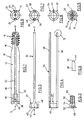
- a femoral neck screw 10 has a cylindrical shaft 12 and a threaded part 14, the shaft 12 via a conical section 16 in the Threaded part 14 passes.
- the tip diameter of the self-tapping thread of the threaded part 14 corresponds approximately to the outer diameter of the shaft 12.
- the threaded part 14 runs into the proximal end of the screw 10.
- the shaft 12 has an internally threaded section 18 which continues into a Through hole 20. The through hole is used to hold a guide spike when implanting the femoral neck screw.
- grooves extend over the entire Length of the nail 10, wherein only one groove 22 can be seen in Fig. 1, while in the Figures 5 and 6 can also be seen a groove 24.
- the grooves are approximately square Cross-section.
- the groove wall widens in a bevel distally, as can be seen at 26 in FIG. 1.
- the groove base has a bevel 28, i.e. seen from the distal end, the groove 22, 24 is initially deeper than in the rest of the region.
- the grooves 22, 24 can be somewhat in the rest of the threaded part 14 have less depth. However, this is not shown.
- a blade 34 is shown in FIGS. 3 and 4 or 7 and 8. it consists of two parallel blade legs 36, 38, which are in one piece with an annular cylindrical Section 37 are formed.
- the blade legs 36, 38 have a square cross section and are dimensioned such that they are accommodated approximately appropriately by the grooves 22, 24 are, the outer sides of the blade legs 36, 38 then approximately in Height of the outside of the shaft 12 lie.
- the outside of the blade legs 36, 38 can be rounded according to the radius of the shaft 12, is required but not this.
- the blades 36, 38 have a first bevel on the outside at the end 44 and on the inner side a bevel 46, which form a tip.
- the Chamfer 46 interacts with chamfer 28 in the bottom of grooves 22, 24, to facilitate the insertion of the fork-shaped blade.
- the Bevels 26 in the groove walls being after full insertion the blade leg 36, 38 in the grooves 22, 24 the triangularly widened sections 48 engage in the space formed between two bevels 26.
- the face of the ring-cylindrical portion 37 facing the blades the distal end of the screw 10.
- the tips of the blade legs 36, 38 stand doing something about the proximal end of the femoral neck screw 10.
- a fastening screw 50 serves for fastening the ring-cylindrical one Section 37 at the distal end of screw 10.
- the mounting screw 50 has a disk-like head 52 of a diameter that is approximately corresponds to the outer diameter of the shaft 12. This is followed by a smoother one Section 54, whose outer diameter is approximately the tip diameter of the Corresponds to the internally threaded section 40 of the ring-cylindrical section.
- a threaded section 56 interacts with the internal thread 18 of the shaft 12.
- the screw 10 is passed, for example, through the oblique bore of a locking nail after a corresponding hole has been drilled in the femur. Drilling is also carried out in the neck and head of the femur. The femoral neck screw is then screwed into the neck or head of the femur, as is known per se.
- a locking screw which is attached to the proximal end of the nail shaft, can cooperate with one of the grooves 30, 32 in order to prevent further rotation after the screw 10 has been screwed in.
- the locking screw can be tightened so that it interacts positively with one of the grooves 30, 32 and thus also represents an axial securing for the screw 10.
- the femoral neck screw 10 is screwed in with the aid of a guide spike, not shown, which has been driven in beforehand and on which the screw is threaded ", the spit extending through the central bore 20.
- the blade legs 36, 38 are inserted and advanced into the grooves 22, 24, until the ring-cylindrical section 37 abuts against the distal end of the screw 10.
- the pointed ends of the blade legs 36, 38 are slightly above that proximal end of the screw 10 over.
- the screw points to actuation 50 a depression 58 with screw surfaces (Allen).
- the set screw can be with regard to one of the grooves 30, 32 something to be solved so that the Screw 10 is still secured against rotation, but can slide axially.
Abstract
Description
Die Erfindung bezieht sich auf eine Schenkelhalsschraube nach dem Oberbegriff des Anspruchs 1.The invention relates to a femoral neck screw according to the preamble of Claim 1.
Aus EP 0 257 118 ist ein Osteosynthesehilfsmittel bekanntgeworden, das aus einem Verriegelungsnagel und einer Schenkelhalsschraube besteht. Der Verriegelungsnagel wird von proximal in den Femur eingetrieben. Der Verriegelungsnagel weist im proximalen Abschnitt eine schräge Durchbohrung auf, deren Achse annähernd zur Achse des Schenkelhalses ausgerichtet ist. Durch diese Bohrung wird eine Schenkelhalsschraube hindurchgeführt. Sie weist einen Gewindeteil auf, der zum Beispiel selbstschneidend ist und der bis in den Kopf des Femurs vorgetrieben wird. Vom proximalen Ende wird in eine Bohrung des Verriegelungsnagels eine Feststellschraube eingeführt, die mit ihrem inneren Ende mit in Umfangsrichtung beabstandeten achsparallelen Nuten im Schaft der Schenkelhalsschraube zusammenwirkt, um die Schenkelhalsschraube gegen Rotation zu sichern, jedoch ein Gleiten in Achsrichtung zuzulassen. Ein derartiges Osteosynthesehilfsmittel dient vorwiegend zur Versorgung von trochanteren und subtrochanteren Frakturen, aber auch zur Versorgung von Frakturen des Schenkelhalses oder von Frakturen im Kopfbereich.From EP 0 257 118 an osteosynthesis aid has become known which consists of a Locking nail and a femoral neck screw. The locking nail is driven into the femur from the proximal end. The locking nail points in proximal section has an oblique hole, the axis of which is approximately to Axis of the femoral neck is aligned. A femoral neck screw is through this hole passed through. It has a threaded part, for example is self-tapping and is driven into the head of the femur. From proximal end is a set screw in a hole in the locking nail introduced with its inner end spaced apart in the circumferential direction axially parallel grooves in the shaft of the femoral neck screw cooperates to the Secure the femoral neck screw against rotation, but slide in the axial direction allow. Such an osteosynthesis aid is primarily used for care of more trochanteric and subtrochanteric fractures, but also for the treatment of Fractures of the femoral neck or fractures in the head area.
Mit Hilfe einer Kompressionsschraube, die in den distalen Bereich der Schenkelhalsschraube eingeschraubt wird und die mit dem Verriegelungsnagel zusammenwirkt, kann auch eine Kompression ausgeübt werden. Dieser Anwendungsfall tritt bei Brüchen im Kopf- und Halsbereich auf.With the help of a compression screw, which is in the distal area of the femoral neck screw is screwed in and which interacts with the locking nail, compression can also be applied. This use case occurs Cracks in the head and neck area.
Zur Anbringung des Verriegelungsnagels und der Halsschraube ist ein Zielinstrumentarium erforderlich, um von außen die Bohrungen im Verriegelungsnagel aufzufinden. Hierfür gibt es die verschiedensten Vorschläge. Die meisten beinhalten ein Instrument, das auf das proximale Ende des Verriegelungsnagels aufgesetzt wird und einen Bügel aufweist, der sich im Abstand parallel zum Femur erstreckt, wenn mit dem Verriegelungsnagel verbunden.A set of target instruments is required for attaching the locking nail and the neck screw required to find the holes in the locking nail from the outside. There are various suggestions for this. Most contain an instrument which is placed on the proximal end of the locking nail and has a bracket that extends parallel to the femur at a distance when with connected to the locking nail.
Bei der Verwendung des beschriebenen Osteosynthesehilfsmittels kann es bei der Versorgung pertrochanterer Femurfrakturen mit kurzem Kopf-Hals-Fragment oder bei erheblicher Osteoporose zu Komplikationen im Bereich der Schenkelhalsschraube kommen. Die Schenkelhalsschraube kann bei reduzierter Knochensubstanz oder kranialer Fehllage ausbrechen. Ferner besteht die Gefahr der sekundären Rotation des Kopf-Hals-Fragments bei exzentrischer Lage de Halsschraube. Es ist ferner bekannt, statt einer Schenkelhalsschraube eine Klinge zu verwenden, welche durch eine Öffnung im Verriegelungsnagel hindurchgeführt wird. Im Hinblick auf die Rotationsstabilität ist eine derartige Klinge günstiger. Das Einbringen der Klinge ist jedoch weitaus problematischer. Außerdem läßt sich mit Hilfe einer Klinge eine Frakturkompression nicht erzielen.When using the osteosynthesis aid described, it can be in the Treatment of pertrochanteric femoral fractures with a short head and neck fragment or at Significant osteoporosis to complications in the area of the femoral neck screw come. The femoral neck screw can be used with reduced bone or cranial Break out of position. There is also a risk of secondary rotation of the Head and neck fragments with eccentric position of the neck screw. It is also known instead of using a femoral neck screw, use a blade that passes through an opening is passed through in the locking nail. In terms of rotational stability such a blade is cheaper. However, the insertion of the blade is far more problematic. Fracture compression can also be performed with the help of a blade do not achieve.
Der Erfindung liegt die Aufgabe zugrunde, eine Schenkelhalsschraube zu schaffen, bei der die lastaufnehmende Fläche im Gewindeteil der Schenkelhalsschraube vergrößert wird.The invention has for its object to provide a femoral neck screw, in which the load-bearing area in the threaded part of the femoral neck screw increases becomes.
Diese Aufgabe wird durch die Merkmale des Anspruchs 1 gelöst.This object is solved by the features of claim 1.
Bei der erfindungsgemäßen Schenkelhalsschraube sind ausgehend vom distalen Ende auf gegenüberliegenden Außenseiten achsparallele Nuten geformt, von denen mindestens eine sich bis in den Gewindeteil hineinerstreckt. Ferner ist eine gabelförmige Klinge vorgesehen, deren Klingenschenkel von den Nuten aufgenommen sind. Der Querschnitt der Klingenschenkel entspricht vorzugsweise dem der Nuten, wobei jedoch ein geringes Spiel gelassen ist. Am distalen Ende sind die Klingenschenkel über einen geeigneten Verbindungsabschnitt miteinander verbunden, der seinerseits in geeigneter Weise mit dem distalen Ende der Halsschraube verbunden wird. Vorzugsweise ist der Verbindungsabschnitt ringzylindrisch und in seinem Außendurchmesser annähernd gleich dem Außendurchmesser des Schaftes der Schenkelhalsschraube. Er kann mit Hilfe einer Schraube, die in ein Innengewinde am distalen Ende der Schenkelhalsschraube eingedreht wird, befestigt werden. Vorzugsweise hat der ringzylindrische Abschnitt seinerseits ein Innengewinde für die Verbindung mit einem geeigneten Einschlaginstrument.In the femoral neck screw according to the invention, starting from the distal end axially parallel grooves are formed on opposite outer sides, of which at least one extends into the threaded part. Furthermore, is a fork-shaped Blade provided, the blade legs are received by the grooves. The Cross-section of the blade legs preferably corresponds to that of the grooves, however a little game is left. The blade legs are over at the distal end a suitable connecting section connected to each other, which in turn in a suitable Way is connected to the distal end of the neck screw. Preferably the connecting section is ring-cylindrical and in its outer diameter approximately the same as the outside diameter of the shaft of the femoral neck screw. He can be screwed into an internal thread at the distal end of the femoral neck screw is screwed in. Preferably, the ring cylindrical Section in turn an internal thread for connection with a suitable one Impact instrument.
Mindestens eine Schenkelhalsklinge erstreckt sich bis in den Bereich des Gewindeteils der Halsschraube oder auch geringfügig darüber hinaus. Vorzugsweise sind jedoch beide Klingenschenkel annähernd gleich lang, so daß beide die lastaufnehmende Fläche im Gewindeteil der Schenkelhalsschraube vergrößern. Dadurch ergibt sich eine effektive Sicherung gegen sekundäre Kopf-Hals-Rotation. Die erfindungsgemäße Schenkelhalsschraube ist besonders vorteilhaft bei der Anwendung bei erheblicher Osteoporose oder exzentrischer Hüftschraubenlage.At least one femoral neck blade extends into the area of the threaded part the neck screw or slightly beyond. However, are preferred both blade legs approximately the same length, so that both the load-bearing Increase the area in the threaded part of the femoral neck screw. This results in a effective protection against secondary head and neck rotation. The invention Femoral neck screw is particularly advantageous when used with considerable Osteoporosis or eccentric hip screw position.
Die Nuten bzw. die Klingenschenkel sind vorzugsweise so ausgelegt, daß im Bereich des Schaftes der Halsschraube die Außenseiten der Klingenschenkel annähernd in Höhe der Außenseite des Schaftes liegen. Die Nuten können nach einer anderen Ausgestaltung der Erfindung im Bereich des Gewindeteils flacher verlaufen, wobei eine Rampe zwischen den verschieden tiefen Nutabschnitten vorgesehen werden kann. The grooves or the blade legs are preferably designed so that in the area the shaft of the neck screw approximately the outside of the blade legs Height of the outside of the shaft. The grooves can have a different design the invention run flat in the area of the threaded part, one Ramp can be provided between the different depth groove sections.
Dadurch kommt es zu einer Spreizung der Klingenschenkel und damit zu einer wirksameren Verankerung.This leads to a spreading of the blade legs and thus to one more effective anchoring.
Nach einer anderen Ausgestaltung der Erfindung weisen die Enden der Klingenschenkel außen eine Anschrägung auf. Dadurch wird das Eintreiben erleichtert. Nach einer anderen Ausgestaltung der Erfindung sind die Enden der Klingenschenkel an der Innenseite angeschrägt, wodurch das Einführen in die Nuten erleichtert wird. Diesem Ziel dienen auch optionale Anschrägungen in den Nutwänden im Eintrittsbereich der Klingen sowie im Boden der Nut.According to another embodiment of the invention, the ends of the blade legs have a bevel on the outside. This makes driving in easier. After a Another embodiment of the invention are the ends of the blade legs on the inside beveled, which facilitates insertion into the grooves. This Optional bevels in the groove walls in the entry area also serve the purpose Blades as well as in the bottom of the groove.
Die Implantation der erfindungsgemäßen Schenkelhalsschraube erfolgt in üblicher Weise. Nach ihrem Eindrehen wird sie in Drehrichtung festgelegt, wie das bei dem eingangs beschriebenen Osteosynthesehilfsmittel der Fall ist, etwa mit Hilfe einer Feststellschraube und achsparallelen Nuten an der Außenseite des Schraubenschaftes. Ggf. kann eine Kompression der Fraktur vorgenommen werden. Anschließend erfolgt das Einschlagen der Klinge, was über einen Bildwandler verfolgt werden kann. Ist die Erstreckung der Klingenschenkel derart, daß sie über das proximale Ende der Halsschraube hinausragen, kann dies am Bildwandler festgestellt werden. Nach dem Entfernen des Einschlagelements kann die Klinge gegen ein Herausgleiten mit Hilfe einer Schraube, die in das beschriebene Innengewinde am proximalen Ende der Schenkelhalsschraube eingedreht wird, gesichert werden. The femoral neck screw according to the invention is usually implanted Wise. After screwing it in, it is fixed in the direction of rotation, like that for the osteosynthesis aid described at the beginning is the case, for example with the help of a Locking screw and axially parallel grooves on the outside of the screw shaft. Possibly. the fracture can be compressed. Then follows hammering in the blade, which can be followed using an image converter. Is the Extension of the blade leg so that it extends over the proximal end of the neck screw protrude, this can be determined on the image converter. After removal of the impact element, the blade can be prevented from sliding out with the aid of a Screw that into the internal thread described on the proximal end of the femoral neck screw is screwed in, secured.
Die erfindungsgemäße Schenkelhalsschraube ist zu dem herkömmlichen oben beschriebenen Osteosynthesehilfsmittel vollständig kompatibel. Es kann das herkömmliche Zielinstrumentarium verwendet werden. Die dynamische Lagerung der Schenkelhalsschraube kann beibehalten werden. Die Handhabung der erfindungsgemäßen Schenkelhalsschraube ist einfach. Auch das Explantieren bereitet keine Probleme. Die erfindungsgemäße Schenkelhalsschraube kann jedoch wahlweise auch ohne Arretierungsklinge eingesetzt werden.The femoral neck screw according to the invention is to the conventional one described above Fully compatible osteosynthesis tools. It can be the conventional one Target instruments can be used. The dynamic mounting of the femoral neck screw can be maintained. The handling of the invention Femoral neck screw is simple. Explanting is also no problem. The However, the femoral neck screw according to the invention can optionally also be used without a locking blade be used.
Der einzige Unterschied, der sich etwa gegenüber den oben beschriebenen herkömmlichen Schenkelhalsschrauben ergibt ist der, daß nur zwei Gleit- und Feststellnuten im Schraubenschaft geformt werden können, weil die die Klinge aufhehmenden Nuten hierfür nicht in Frage kommen.The only difference that is about compared to the conventional ones described above Femoral neck screws results in the fact that only two sliding and locking grooves in the Screw shaft can be formed because of the grooves receiving the blade are out of the question.
Die Erfindung wird nachfolgend anhand eines in Zeichnungen dargestellten Ausführungsbeispiels näher erläutert.
- Fig. 1
- zeigt schematisch in Seitenansicht eine Schenkelhalsschraube nach der Erfindung.
- Fig. 2
- zeigt eine Schraube, die in das distale Ende der Schraube nach Fig. 1 einschraubbar ist.
- Fig. 3
- zeigt eine erste Seitenansicht einer Klinge zwecks Verbindung mit der Schraube nach Fig. 1.
- Fig. 4
- zeigt die um 90° verdrehte Seitenansicht der Klinge nach Fig. 3.
- Fig. 5
- zeigt die Endansicht der Schraube nach Fig. 1 in Richtung Pfeil 5.
- Fig. 6
- zeigt die Endansicht der Schraube nach Fig. 1 in
Richtung Pfeil 6. - Fig. 7
- zeigt die Endansicht der Klinge nach Fig. 3 in
Richtung Pfeil 7. - Fig. 8
- zeigt die Endansicht der Klinge nach Fig. 3 in
Richtung Pfeil 8. - Fig. 9
- zeigt die Einzelheit vergrößert des Klingenendes nach Fig. 4.
- Fig. 1
- shows schematically in side view a femoral neck screw according to the invention.
- Fig. 2
- shows a screw which can be screwed into the distal end of the screw of FIG. 1.
- Fig. 3
- shows a first side view of a blade for connection to the screw of FIG. 1st
- Fig. 4
- shows the side view of the blade of FIG. 3 rotated by 90 °.
- Fig. 5
- shows the end view of the screw of FIG. 1 in the direction of
arrow 5. - Fig. 6
- shows the end view of the screw of FIG. 1 in the direction of
arrow 6. - Fig. 7
- shows the end view of the blade of FIG. 3 in the direction of arrow 7th
- Fig. 8
- shows the end view of the blade of FIG. 3 in the direction of
arrow 8. - Fig. 9
- shows the detail enlarged of the blade end of FIG. 4th
Eine Schenkelhalsschraube 10 nach Fig. 1 weist einen zylindrischen Schaft 12 auf und
ein Gewindeteil 14, wobei der Schaft 12 über einen konischen Abschnitt 16 in den
Gewindeteil 14 übergeht. Der Spitzendurchmesser des selbstschneidenden Gewindes
des Gewindeteils 14 entspricht annähernd dem Außendurchmesser des Schaftes 12.
Der Gewindeteil 14 läuft in das proximale Ende der Schraube 10 aus. Am distalen
Ende weist der Schaft 12 einen Innengewindeabschnitt 18 auf, der sich fortsetzt in eine
Durchbohrung 20. Die Durchbohrung dient für die Aufnahme eines Führungsspießes
beim Implantieren der Schenkelhalsschraube.A
Auf diametral gegenüberliegenden Seiten erstrecken sich Nuten über die gesamte
Länge des Nagels 10, wobei in Fig. 1 nur eine Nut 22 zu erkennen ist, während in den
Figuren 5 und 6 auch eine Nut 24 zu sehen ist. Die Nuten haben annähernd quadratischen
Querschnitt. Die Nutwandung erweitert sich nach distal in einer Schrägung,
wie bei 26 in Fig. 1 zu erkennen. Der Nutgrund weist eine Anschrägung 28 auf, d.h.
die Nut 22, 24 ist vom distalen Ende her gesehen zunächst tiefer als im restlichen Bereich.
Die Nuten 22, 24 können im übrigen im Bereich des Gewindeteils 14 eine etwas
geringere Tiefe haben. Dies ist jedoch nicht dargestellt.On diametrically opposite sides, grooves extend over the entire
Length of the
Auf diametral gegenüberliegenden Seiten, mithin jeweils um 90° gegenüber den
Nuten 22, 24 versetzt, sind Gleitnuten 30, 32 im hinteren bzw. distalen Bereich des
Schaftes 12 eingeformt. Sie sind in Fig. 1 gestrichelt angedeutet. Auf ihre Funktion
wird weiter unten noch eingegangen.On diametrically opposite sides, therefore in each case by 90 ° in relation to the
In den Figuren 3 und 4 bzw. 7 und 8 ist eine Klinge 34 dargestellt. Sie besteht aus
zwei parallelen Klingenschenkeln 36, 38, die einteilig mit einem ringzylindrischen
Abschnitt 37 geformt sind. Die Klingenschenkel 36, 38 haben quadratischen Querschnitt
und sind so bemessen, daß sie annähernd passend von den Nuten 22, 24 aufgenommen
sind, wobei dann die Außenseiten der Klingenschenkel 36, 38 annähernd in
Höhe der Außenseite des Schaftes 12 liegen. Die Außenseiten der Klingenschenkel 36,
38 können entsprechend zum Radius des Schaftes 12 gerundet sein, erforderlich ist
dies jedoch nicht.A
Der ringzylindrische Abschnitt 37 hat einen Außendurchmesser, der annähernd dem
Außendurchmesser des Schaftes 12 der Schraube 10 entspricht. Er weist außerdem einen
Innengewindeabschnitt 40 auf, in den ein Gewindeabschnitt eines nicht gezeigten
Einschlaginstruments eingeschraubt werden kann. An dem den Schenkeln 36, 38 gegenüberliegenden
Ende weist der ringzylindrische Abschnitt 37 zwei diametrale Einschnitte
42 auf. In diese können entsprechende Vorsprünge des Einschlaginstruments
eingreifen, um eine Drehung zwischen dem Einschlaginstrument und der Klinge 34 zu
verhindern.The ring-
Wie insbesondere aus Fig. 9 hervorgeht, in der das vordere Ende der Klinge 34 dargestellt
ist, weisen die Klingen 36, 38 am Ende an der Außenseite eine erste Anschrägung
44 und an der inneren Seite eine Anschrägung 46 auf, die eine Spitze bilden. Die
Anschrägung 46 wirkt mit der Anschrägung 28 im Boden der Nuten 22, 24 zusammen,
um das Einführen der gabelförmigen Klinge zu erleichtern. Hierzu dienen auch die
Anschrägungen 26 in den Nutwandungen, wobei nach dem vollständigen Einführen
der Klingenschenkel 36, 38 in die Nuten 22, 24 die dreieckig verbreiterten Abschnitte
48 in den Raum eingreifen, der zwischen zwei Anschrägungen 26 gebildet ist. Dabei
liegt die den Klingen zugewandte Stirnseite des ringzylindrischen Abschnitts 37 gegen
das distale Ende der Schraube 10 an. Die Spitzen der Klingenschenkel 36, 38 stehen
dabei etwas über das proximale Ende der Schenkelhalsschraube 10 über.As can be seen in particular from Fig. 9, in which the front end of the
Eine Befestigungsschraube 50 gemäß Fig. 2 dient zur Befestigung des ringzylindrischen
Abschnitts 37 am distalen Ende der Schraube 10. Die Befestigungsschraube
50 weist einen scheibenartigen Kopf 52 auf von einem Durchmesser, der annähernd
dem Außendurchmesser des Schaftes 12 entspricht. Hieran schließt sich ein glatter
Abschnitt 54 an, dessen Außendurchmesser annähernd dem Spitzendurchmesser des
Innengewindeabschnitts 40 des ringzylindrischen Abschnitts entspricht. Ein Gewindeabschnitt
56 wirkt mit dem Innengewinde 18 des Schaftes 12 zusammen.A
Bei der Implantation wird die Schraube 10 zum Beispiel durch die Schrägdurchbohrung
eines Verriegelungsnagels hindurchgeführt, nachdem ein entsprechendes Loch
im Femur gebohrt wurde. Ferner erfolgt eine Vorbohrung im Hals und Kopf des
Femurs. Die Schenkelhalsschraube wird dann in den Hals bzw. Kopf des Femurs eingeschraubt,
wie dies an sich bekannt ist. Eine Feststellschraube, die am proximalen
Ende des Nagelschaftes angebracht ist, kann mit einer der Nuten 30, 32 zusammenwirken,
um nach dem Eindrehen der Schraube 10 eine weitere Drehung zu verhindern.
Um auch die axiale Lage der Schraube 10 zu sichern, kann die Feststellschraube angezogen
werden, daß sie kraftschlüssig mit einer der Nuten 30, 32 zusammenwirkt und
somit auch eine axiale Sicherung für die Schraube 10 darstellt. Das Einschrauben der
Schenkelhalssschraube 10 erfolgt mit Hilfe eines nicht gezeigten Führungsspießes, der
zuvor eingetrieben worden ist und auf dem die Schraube ![]()
![]()
Anschließend wird die in den Figuren 1 bis 3 und 4 bzw. 7 und 8 dargestellte Klinge
eingeschlagen, und zwar mit Hilfe eines Instruments, das mit dem Gewindeabschnitt
40 zusammenwirkt.Then the blade shown in Figures 1 to 3 and 4 or 7 and 8
hammered, with the help of an instrument with the threaded
Die Klingenschenkel 36, 38 werden in die Nuten 22, 24 eingeführt und vorgetrieben,
bis der ringzylindrische Abschnitt 37 gegen das distale Ende der Schraube 10 anschlägt.
Die spitzen Enden der Klingenschenkel 36, 38 stehen dabei etwas über das
proximale Ende der Schraube 10 über. Danach wird mit Hilfe der Schraube 50 die
Klinge 34 am Schaft 12 der Schraube 10 festgelegt. Zur Betätigung weist die Schraube
50 eine Einsenkung 58 auf mit Schraubenflächen (Inbus).The
Sobald die Klinge 34 auf die beschriebene Weise befestigt ist, kann die Feststellschraube
im Hinblick auf eine der Nuten 30, 32 etwas gelöst werden, so daß die
Schraube 10 zwar nach wie vor gegen Drehung gesichert ist, jedoch axial gleiten kann.Once the
Claims (11)
Applications Claiming Priority (2)
| Application Number | Priority Date | Filing Date | Title |
|---|---|---|---|
| DE29823113U | 1998-12-28 | ||
| DE29823113U DE29823113U1 (en) | 1998-12-28 | 1998-12-28 | Femoral neck screw |
Publications (3)
| Publication Number | Publication Date |
|---|---|
| EP1016382A2 true EP1016382A2 (en) | 2000-07-05 |
| EP1016382A3 EP1016382A3 (en) | 2001-09-05 |
| EP1016382B1 EP1016382B1 (en) | 2006-05-10 |
Family
ID=8067229
Family Applications (1)
| Application Number | Title | Priority Date | Filing Date |
|---|---|---|---|
| EP99124270A Expired - Lifetime EP1016382B1 (en) | 1998-12-28 | 1999-12-04 | Femoral neck screw |
Country Status (5)
| Country | Link |
|---|---|
| US (1) | US6423066B1 (en) |
| EP (1) | EP1016382B1 (en) |
| JP (1) | JP3778753B2 (en) |
| DE (2) | DE29823113U1 (en) |
| ES (1) | ES2264238T3 (en) |
Cited By (6)
| Publication number | Priority date | Publication date | Assignee | Title |
|---|---|---|---|---|
| US6423066B1 (en) | 1998-12-28 | 2002-07-23 | Stryker Trauma Gmbh | Neck screw |
| US7001392B2 (en) | 2003-01-29 | 2006-02-21 | Howmedica Osteonics Corp. | Apparatus and method for preparing bone for antirotational implantation of an orthopedic endoprosthesis |
| WO2011044917A1 (en) * | 2009-10-13 | 2011-04-21 | Zimmer Gmbh | An orthopedic nail and an orthopedic nail system |
| US8114078B2 (en) * | 2003-04-09 | 2012-02-14 | Synthes Usa, Llc | Intramedullary nail for femur fracture fixation |
| US8888779B2 (en) * | 2003-03-07 | 2014-11-18 | DePuy Synthes Products, LLC | Locking screw for an intramedullary nail |
| EP2845553A1 (en) * | 2013-09-05 | 2015-03-11 | Biedermann Technologies GmbH & Co. KG | Bone anchor and bone anchor assembly comprising the same |
Families Citing this family (38)
| Publication number | Priority date | Publication date | Assignee | Title |
|---|---|---|---|---|
| US6527775B1 (en) | 2000-09-22 | 2003-03-04 | Piper Medical, Inc. | Intramedullary interlocking fixation device for the distal radius |
| DE20208922U1 (en) * | 2002-06-05 | 2003-10-09 | Stryker Trauma Gmbh | The neck screw |
| US20050101961A1 (en) * | 2003-11-12 | 2005-05-12 | Huebner Randall J. | Bone screws |
| US7179260B2 (en) | 2003-09-29 | 2007-02-20 | Smith & Nephew, Inc. | Bone plates and bone plate assemblies |
| AU2003299542B2 (en) | 2002-10-03 | 2009-01-15 | Virginia Tech Intellectual Properties, Inc. | Magnetic targeting device |
| EP1415605B1 (en) * | 2002-11-04 | 2010-10-13 | Zimmer GmbH | Bone fixation system |
| US20050055024A1 (en) * | 2003-09-08 | 2005-03-10 | James Anthony H. | Orthopaedic implant and screw assembly |
| US7799030B2 (en) * | 2003-09-08 | 2010-09-21 | Smith & Nephew, Inc. | Orthopaedic plate and screw assembly |
| US7780667B2 (en) * | 2003-09-08 | 2010-08-24 | Smith & Nephew, Inc. | Orthopaedic plate and screw assembly |
| DE50312145D1 (en) * | 2003-09-18 | 2009-12-31 | Synthes Gmbh | DEVICE FOR TREATING FRACTURES OF THE FEMUR |
| US20050216027A1 (en) * | 2004-03-24 | 2005-09-29 | Suh Sean S | Extraction screwdriver |
| US7588577B2 (en) | 2004-07-15 | 2009-09-15 | Wright Medical Technology, Inc. | Guide assembly for intramedullary fixation and method of using the same |
| US20060015101A1 (en) | 2004-07-15 | 2006-01-19 | Wright Medical Technology, Inc. | Intramedullary fixation assembly and devices and methods for installing the same |
| CA2619500C (en) * | 2005-08-15 | 2012-04-17 | Synthes (U.S.A.) | Osteosynthetic device |
| JP2009509660A (en) * | 2005-09-28 | 2009-03-12 | スミス アンド ネフュー インコーポレーテッド | Equipment for reducing femoral neck fractures |
| US8579985B2 (en) | 2006-12-07 | 2013-11-12 | Ihip Surgical, Llc | Method and apparatus for hip replacement |
| CA2671523C (en) | 2006-12-07 | 2013-02-12 | Anatol Podolsky | Method and apparatus for total hip replacement |
| US8974540B2 (en) | 2006-12-07 | 2015-03-10 | Ihip Surgical, Llc | Method and apparatus for attachment in a modular hip replacement or fracture fixation device |
| US8317845B2 (en) * | 2007-01-19 | 2012-11-27 | Alexa Medical, Llc | Screw and method of use |
| US7909882B2 (en) | 2007-01-19 | 2011-03-22 | Albert Stinnette | Socket and prosthesis for joint replacement |
| US7918853B2 (en) * | 2007-03-20 | 2011-04-05 | Smith & Nephew, Inc. | Orthopaedic plate and screw assembly |
| US8771283B2 (en) | 2007-12-17 | 2014-07-08 | Wright Medical Technology, Inc. | Guide assembly for intramedullary fixation and method of using the same |
| US8100911B2 (en) * | 2008-06-30 | 2012-01-24 | Depuy Products, Inc. | Fracture fixation apparatus |
| US8808292B2 (en) | 2008-11-11 | 2014-08-19 | Zimmer Gmbh | Orthopedic screw |
| WO2010123879A1 (en) * | 2009-04-20 | 2010-10-28 | Virginia Tech Intellectual Properties, Inc. | Intramedullary nail targeting device |
| US8419735B2 (en) * | 2009-05-05 | 2013-04-16 | Synthes Usa, Llc | Nail locking systems |
| BRPI1011556A2 (en) | 2009-06-30 | 2016-03-29 | Smith & Nephew Inc | orthopedic implant and fixation assembly |
| US8449544B2 (en) | 2009-06-30 | 2013-05-28 | Smith & Nephew, Inc. | Orthopaedic implant and fastener assembly |
| US20130041414A1 (en) * | 2010-03-10 | 2013-02-14 | Advanced Orthopaedic Solutions, Inc. | Telescoping Bone Screw |
| US20120310283A1 (en) * | 2011-06-02 | 2012-12-06 | Morreale Vittorio M | Segmental spinal fixation system and a method of fixating a plurality of spinal segments |
| US9345522B2 (en) * | 2012-05-22 | 2016-05-24 | Matthew Songer | Bone fixation screw and method |
| US9050137B2 (en) * | 2012-06-04 | 2015-06-09 | Virak Orthopedic Research Llc | Interchangeable orthopedic blade |
| US9320555B2 (en) | 2013-01-31 | 2016-04-26 | Stryker European Holdings I, Llc | Modular lag screw |
| US10363075B2 (en) * | 2015-02-09 | 2019-07-30 | Yingze Zhang | Porous bionic internal fixation device for promoting healing of fractured bone |
| CN104688312A (en) * | 2015-03-17 | 2015-06-10 | 苏州瑞华医院有限公司 | Locking plate type intramedullary nail for femoral intertrochanteric fracture treatment |
| WO2018100418A1 (en) * | 2016-12-02 | 2018-06-07 | Stryker European Holdings I, Llc | Orthopedic locking screw |
| US20200205870A1 (en) * | 2017-09-08 | 2020-07-02 | Device Synergies, PTY LTD | Cannulated fixation device |
| MX2020003481A (en) | 2017-10-11 | 2020-12-07 | Howmedica Osteonics Corp | Humeral fixation plate guides. |
Citations (1)
| Publication number | Priority date | Publication date | Assignee | Title |
|---|---|---|---|---|
| EP0257118A1 (en) | 1986-07-30 | 1988-03-02 | Howmedica GmbH | Osteosynthesis device for the treatment of subtrochanteric fractures |
Family Cites Families (22)
| Publication number | Priority date | Publication date | Assignee | Title |
|---|---|---|---|---|
| US3892233A (en) * | 1972-06-26 | 1975-07-01 | Gunnar W Vestby | Hip nail |
| US3996931A (en) * | 1975-07-03 | 1976-12-14 | Callender Jr George R | Fractured bone setting fastener assembly |
| US4457301A (en) * | 1982-06-18 | 1984-07-03 | Howmedica Inc. | Intramedullary fixation device |
| DE3509417A1 (en) * | 1985-03-15 | 1986-09-25 | geb. Goos Hildegund Dr. 2300 Kiel Ewers | Device for promoting osteosynthesis in bone surgery |
| IL80705A0 (en) * | 1985-11-28 | 1987-02-27 | Jaquet Orthopedie | Transcutaneous pin for fixation of a bone part or fragment |
| GB8722370D0 (en) * | 1987-09-23 | 1987-10-28 | Halder S C | Fixating device |
| US5176681A (en) | 1987-12-14 | 1993-01-05 | Howmedica International Inc. | Intramedullary intertrochanteric fracture fixation appliance and fitting device |
| US5112333A (en) * | 1990-02-07 | 1992-05-12 | Fixel Irving E | Intramedullary nail |
| GB9113578D0 (en) | 1991-06-24 | 1991-08-14 | Howmedica | Intramedullary intertrochanteric fracture fixation appliance |
| DE4124007C1 (en) * | 1991-07-19 | 1992-11-05 | Dietmar Dr.Med. Priv. Doz. 4400 Muenster De Pennig | |
| DE9200328U1 (en) * | 1992-01-14 | 1992-02-27 | Howmedica Gmbh, 2314 Schoenkirchen, De | |
| US5380334A (en) * | 1993-02-17 | 1995-01-10 | Smith & Nephew Dyonics, Inc. | Soft tissue anchors and systems for implantation |
| SE9301405D0 (en) * | 1993-04-27 | 1993-04-27 | Medevelop Ab | BEFORE IMPLANTATION IN WEAVEN PROVIDED, MAINLY ROTATION SYMETRICALLY TRAINED ANCHORING ORGANIZATION, CONDUCTING PROTESTS OR DIFFICULTLY, ANCHORING DEVICE COMPLETED FOR APPLICATION OF SUFFICIENT ANCHORING |
| US5352229A (en) * | 1993-05-12 | 1994-10-04 | Marlowe Goble E | Arbor press staple and washer and method for its use |
| US5489210A (en) * | 1994-05-13 | 1996-02-06 | Hanosh; Frederick N. | Expanding dental implant and method for its use |
| US5643320A (en) * | 1995-03-13 | 1997-07-01 | Depuy Inc. | Soft tissue anchor and method |
| US5782919A (en) * | 1995-03-27 | 1998-07-21 | Sdgi Holdings, Inc. | Interbody fusion device and method for restoration of normal spinal anatomy |
| FR2735010B1 (en) * | 1995-06-07 | 1997-12-05 | Worcel Alexandre | RING OF OSTEOSYNTHESIS USABLE IN COMBINATION WITH A SPINDLE OR A SCREW, AND ANCILLARY FOR ITS COMPRESSION. |
| DE19601477C2 (en) * | 1996-01-17 | 1999-12-16 | Axel Kirsch | Fastening nail |
| DE29600879U1 (en) * | 1996-01-19 | 1996-03-28 | Howmedica Gmbh | Spinal implant |
| US5827287A (en) * | 1996-06-10 | 1998-10-27 | Howmedica Inc. | High strength internal bone fixation devices and process for forming same |
| DE29823113U1 (en) | 1998-12-28 | 2000-05-11 | Howmedica Gmbh | Femoral neck screw |
-
1998
- 1998-12-28 DE DE29823113U patent/DE29823113U1/en not_active Expired - Lifetime
-
1999
- 1999-12-04 DE DE59913410T patent/DE59913410D1/en not_active Expired - Lifetime
- 1999-12-04 EP EP99124270A patent/EP1016382B1/en not_active Expired - Lifetime
- 1999-12-04 ES ES99124270T patent/ES2264238T3/en not_active Expired - Lifetime
- 1999-12-21 US US09/468,655 patent/US6423066B1/en not_active Expired - Lifetime
- 1999-12-28 JP JP37272899A patent/JP3778753B2/en not_active Expired - Lifetime
Patent Citations (1)
| Publication number | Priority date | Publication date | Assignee | Title |
|---|---|---|---|---|
| EP0257118A1 (en) | 1986-07-30 | 1988-03-02 | Howmedica GmbH | Osteosynthesis device for the treatment of subtrochanteric fractures |
Cited By (10)
| Publication number | Priority date | Publication date | Assignee | Title |
|---|---|---|---|---|
| US6423066B1 (en) | 1998-12-28 | 2002-07-23 | Stryker Trauma Gmbh | Neck screw |
| US7001392B2 (en) | 2003-01-29 | 2006-02-21 | Howmedica Osteonics Corp. | Apparatus and method for preparing bone for antirotational implantation of an orthopedic endoprosthesis |
| US7955338B2 (en) | 2003-01-29 | 2011-06-07 | Howmedica Osteoenics Corp. | Apparatus and method for preparing bone for anti-rotational implantation of an orthopedic endoprosthesis |
| US8888779B2 (en) * | 2003-03-07 | 2014-11-18 | DePuy Synthes Products, LLC | Locking screw for an intramedullary nail |
| US8114078B2 (en) * | 2003-04-09 | 2012-02-14 | Synthes Usa, Llc | Intramedullary nail for femur fracture fixation |
| WO2011044917A1 (en) * | 2009-10-13 | 2011-04-21 | Zimmer Gmbh | An orthopedic nail and an orthopedic nail system |
| WO2011045025A1 (en) * | 2009-10-13 | 2011-04-21 | Zimmer Gmbh | An orthopedic nail and an orthopedic nail system |
| US9532818B2 (en) | 2009-10-13 | 2017-01-03 | Zimmer Gmbh | Orthopedic nail and an orthopedic nail system |
| EP2845553A1 (en) * | 2013-09-05 | 2015-03-11 | Biedermann Technologies GmbH & Co. KG | Bone anchor and bone anchor assembly comprising the same |
| CN104414726A (en) * | 2013-09-05 | 2015-03-18 | 比德尔曼技术有限责任两合公司 | Bone anchor and bone anchor assembly comprising the same |
Also Published As
| Publication number | Publication date |
|---|---|
| JP3778753B2 (en) | 2006-05-24 |
| US20020045900A1 (en) | 2002-04-18 |
| US6423066B1 (en) | 2002-07-23 |
| ES2264238T3 (en) | 2006-12-16 |
| EP1016382B1 (en) | 2006-05-10 |
| EP1016382A3 (en) | 2001-09-05 |
| JP2000229093A (en) | 2000-08-22 |
| DE29823113U1 (en) | 2000-05-11 |
| DE59913410D1 (en) | 2006-06-14 |
Similar Documents
| Publication | Publication Date | Title |
|---|---|---|
| EP1016382B1 (en) | Femoral neck screw | |
| EP0226701B1 (en) | Intermedullary pin for osteosynthesis of upper arm fractures | |
| EP0409364B1 (en) | Junction element for osteosynthesis | |
| DE3541597C2 (en) | ||
| EP1175871B1 (en) | Locking nail | |
| EP1615571B1 (en) | Intramedullary nail for femur fracture fixation | |
| EP0917449B1 (en) | Device for attaching fractured hip-joint heads | |
| EP2440147B1 (en) | Surgical instrument with bone screw | |
| DE102005007674B4 (en) | Orthopedic fixation system | |
| DE69923962T2 (en) | BONE IMPLANT WITH A REVERSIBLE FASTENING DEVICE | |
| EP1082063B1 (en) | Surgical blind rivets with closing elements | |
| DE69922023T2 (en) | FIXING DEVICE FOR MEDICAL DRILLING | |
| EP0736286A2 (en) | Osteosynthetic device for treating subtrochanteric and pertrochanteric fractures and fractures of the neck of the femur | |
| EP1405607A1 (en) | Bone screw and bone screw with holding element | |
| CH668173A5 (en) | DEVICE FOR FIXING TUBE BONE FRACTURES WITH A BONE MARBLE NAIL AND AT LEAST ONE CROSS-BOLT LOCKING. | |
| WO1999020195A1 (en) | Bone fixation device | |
| EP1096892A1 (en) | Osteosynthesis screw, especially for application by a translaminar vertebral screw | |
| EP1372502A1 (en) | Anchor element | |
| DE2542263A1 (en) | Osteo synthetic pin for bone fractures - has slotted ends which are expanded by screwed spindle | |
| EP0589235A1 (en) | Bolt for introducing into bone tissue | |
| DE102007045886B4 (en) | Foot surgery bone plate, a wrapping system and fixation system | |
| EP2029037B1 (en) | Femoral head implant | |
| WO2003053265A1 (en) | Modular bone nail | |
| WO2016083355A1 (en) | Securing element | |
| AT403543B (en) | Device for treating femoral neck fractures |
Legal Events
| Date | Code | Title | Description |
|---|---|---|---|
| PUAI | Public reference made under article 153(3) epc to a published international application that has entered the european phase |
Free format text: ORIGINAL CODE: 0009012 |
|
| AK | Designated contracting states |
Kind code of ref document: A2 Designated state(s): AT BE CH CY DE DK ES FI FR GB GR IE IT LI LU MC NL PT SE |
|
| AX | Request for extension of the european patent |
Free format text: AL;LT;LV;MK;RO;SI |
|
| RAP1 | Party data changed (applicant data changed or rights of an application transferred) |
Owner name: STRYKER TRAUMA GMBH |
|
| PUAL | Search report despatched |
Free format text: ORIGINAL CODE: 0009013 |
|
| AK | Designated contracting states |
Kind code of ref document: A3 Designated state(s): AT BE CH CY DE DK ES FI FR GB GR IE IT LI LU MC NL PT SE |
|
| AX | Request for extension of the european patent |
Free format text: AL;LT;LV;MK;RO;SI |
|
| 17P | Request for examination filed |
Effective date: 20011221 |
|
| AKX | Designation fees paid |
Free format text: CH DE ES FR GB IT LI |
|
| GRAP | Despatch of communication of intention to grant a patent |
Free format text: ORIGINAL CODE: EPIDOSNIGR1 |
|
| GRAS | Grant fee paid |
Free format text: ORIGINAL CODE: EPIDOSNIGR3 |
|
| GRAA | (expected) grant |
Free format text: ORIGINAL CODE: 0009210 |
|
| AK | Designated contracting states |
Kind code of ref document: B1 Designated state(s): CH DE ES FR GB IT LI |
|
| REG | Reference to a national code |
Ref country code: GB Ref legal event code: FG4D Free format text: NOT ENGLISH |
|
| REG | Reference to a national code |
Ref country code: CH Ref legal event code: EP |
|
| REF | Corresponds to: |
Ref document number: 59913410 Country of ref document: DE Date of ref document: 20060614 Kind code of ref document: P |
|
| REG | Reference to a national code |
Ref country code: CH Ref legal event code: NV Representative=s name: ISLER & PEDRAZZINI AG |
|
| GBT | Gb: translation of ep patent filed (gb section 77(6)(a)/1977) |
Effective date: 20060831 |
|
| REG | Reference to a national code |
Ref country code: ES Ref legal event code: FG2A Ref document number: 2264238 Country of ref document: ES Kind code of ref document: T3 |
|
| ET | Fr: translation filed | ||
| PLBE | No opposition filed within time limit |
Free format text: ORIGINAL CODE: 0009261 |
|
| STAA | Information on the status of an ep patent application or granted ep patent |
Free format text: STATUS: NO OPPOSITION FILED WITHIN TIME LIMIT |
|
| 26N | No opposition filed |
Effective date: 20070213 |
|
| REG | Reference to a national code |
Ref country code: CH Ref legal event code: PCAR Free format text: ISLER & PEDRAZZINI AG;POSTFACH 1772;8027 ZUERICH (CH) |
|
| REG | Reference to a national code |
Ref country code: FR Ref legal event code: PLFP Year of fee payment: 17 |
|
| REG | Reference to a national code |
Ref country code: CH Ref legal event code: PUE Owner name: STRYKER EUROPEAN HOLDINGS VI, LLC, US Free format text: FORMER OWNER: STRYKER TRAUMA GMBH, DE Ref country code: CH Ref legal event code: PUE Owner name: STRYKER EUROPEAN HOLDINGS I, LLC, US Free format text: FORMER OWNER: STRYKER EUROPEAN HOLDINGS VI, LLC, US |
|
| REG | Reference to a national code |
Ref country code: DE Ref legal event code: R082 Ref document number: 59913410 Country of ref document: DE Representative=s name: MAIWALD PATENTANWALTS- UND RECHTSANWALTSGESELL, DE Ref country code: DE Ref legal event code: R082 Ref document number: 59913410 Country of ref document: DE Representative=s name: MAIWALD PATENTANWALTSGESELLSCHAFT MBH, DE Ref country code: DE Ref legal event code: R081 Ref document number: 59913410 Country of ref document: DE Owner name: STRYKER EUROPEAN HOLDINGS I, LLC (N.D. GES. D., US Free format text: FORMER OWNER: STRYKER EUROPEAN HOLDINGS VI, LLC (N.D. GES. D. STAATES DELAWARE), KALAMAZOO, MICH., US Ref country code: DE Ref legal event code: R081 Ref document number: 59913410 Country of ref document: DE Owner name: STRYKER EUROPEAN HOLDINGS I, LLC (N.D. GES. D., US Free format text: FORMER OWNER: STRYKER TRAUMA GMBH, 24232 SCHOENKIRCHEN, DE |
|
| REG | Reference to a national code |
Ref country code: GB Ref legal event code: 732E Free format text: REGISTERED BETWEEN 20161006 AND 20161012 |
|
| REG | Reference to a national code |
Ref country code: GB Ref legal event code: 732E Free format text: REGISTERED BETWEEN 20161013 AND 20161019 |
|
| REG | Reference to a national code |
Ref country code: FR Ref legal event code: PLFP Year of fee payment: 18 |
|
| REG | Reference to a national code |
Ref country code: ES Ref legal event code: PC2A Owner name: STRYKER EUROPEAN HOLDINGS I, LLC Effective date: 20161115 |
|
| REG | Reference to a national code |
Ref country code: FR Ref legal event code: TP Owner name: STRYKER EUROPEAN HOLDINGS I, LLC, US Effective date: 20161108 |
|
| REG | Reference to a national code |
Ref country code: FR Ref legal event code: PLFP Year of fee payment: 19 |
|
| REG | Reference to a national code |
Ref country code: FR Ref legal event code: PLFP Year of fee payment: 20 |
|
| PGFP | Annual fee paid to national office [announced via postgrant information from national office to epo] |
Ref country code: DE Payment date: 20181120 Year of fee payment: 20 |
|
| PGFP | Annual fee paid to national office [announced via postgrant information from national office to epo] |
Ref country code: FR Payment date: 20181011 Year of fee payment: 20 Ref country code: GB Payment date: 20181128 Year of fee payment: 20 Ref country code: CH Payment date: 20181217 Year of fee payment: 20 |
|
| PGFP | Annual fee paid to national office [announced via postgrant information from national office to epo] |
Ref country code: ES Payment date: 20190102 Year of fee payment: 20 Ref country code: IT Payment date: 20181220 Year of fee payment: 20 |
|
| REG | Reference to a national code |
Ref country code: DE Ref legal event code: R071 Ref document number: 59913410 Country of ref document: DE |
|
| REG | Reference to a national code |
Ref country code: CH Ref legal event code: PL |
|
| REG | Reference to a national code |
Ref country code: GB Ref legal event code: PE20 Expiry date: 20191203 |
|
| PG25 | Lapsed in a contracting state [announced via postgrant information from national office to epo] |
Ref country code: GB Free format text: LAPSE BECAUSE OF EXPIRATION OF PROTECTION Effective date: 20191203 |
|
| REG | Reference to a national code |
Ref country code: ES Ref legal event code: FD2A Effective date: 20200904 |
|
| PG25 | Lapsed in a contracting state [announced via postgrant information from national office to epo] |
Ref country code: ES Free format text: LAPSE BECAUSE OF EXPIRATION OF PROTECTION Effective date: 20191205 |