EP1017321B1 - Percutaneous and hiatal devices for use in minimally invasive pelvic surgery - Google Patents
Percutaneous and hiatal devices for use in minimally invasive pelvic surgery Download PDFInfo
- Publication number
- EP1017321B1 EP1017321B1 EP98907503A EP98907503A EP1017321B1 EP 1017321 B1 EP1017321 B1 EP 1017321B1 EP 98907503 A EP98907503 A EP 98907503A EP 98907503 A EP98907503 A EP 98907503A EP 1017321 B1 EP1017321 B1 EP 1017321B1
- Authority
- EP
- European Patent Office
- Prior art keywords
- guide member
- placement device
- shaft
- member placement
- blunt
- Prior art date
- Legal status (The legal status is an assumption and is not a legal conclusion. Google has not performed a legal analysis and makes no representation as to the accuracy of the status listed.)
- Expired - Lifetime
Links
- 238000001356 surgical procedure Methods 0.000 title description 2
- 238000002224 dissection Methods 0.000 claims description 26
- 238000004891 communication Methods 0.000 claims description 9
- 239000012530 fluid Substances 0.000 claims description 9
- 230000000295 complement effect Effects 0.000 claims description 6
- 239000007769 metal material Substances 0.000 claims 1
- 238000000034 method Methods 0.000 abstract description 25
- 206010046543 Urinary incontinence Diseases 0.000 abstract description 10
- 238000013459 approach Methods 0.000 abstract description 5
- 230000002485 urinary effect Effects 0.000 abstract description 4
- 210000001519 tissue Anatomy 0.000 description 38
- 210000003708 urethra Anatomy 0.000 description 34
- 230000006641 stabilisation Effects 0.000 description 8
- 238000011105 stabilization Methods 0.000 description 8
- 210000000988 bone and bone Anatomy 0.000 description 6
- 230000000087 stabilizing effect Effects 0.000 description 5
- 229910001220 stainless steel Inorganic materials 0.000 description 5
- 210000001215 vagina Anatomy 0.000 description 5
- 239000004033 plastic Substances 0.000 description 4
- 229920003023 plastic Polymers 0.000 description 4
- 210000003689 pubic bone Anatomy 0.000 description 4
- 239000010935 stainless steel Substances 0.000 description 4
- 206010021639 Incontinence Diseases 0.000 description 3
- 239000002184 metal Substances 0.000 description 3
- 229910052751 metal Inorganic materials 0.000 description 3
- 210000005070 sphincter Anatomy 0.000 description 3
- 239000004676 acrylonitrile butadiene styrene Substances 0.000 description 2
- 210000003195 fascia Anatomy 0.000 description 2
- 238000003780 insertion Methods 0.000 description 2
- 230000037431 insertion Effects 0.000 description 2
- 239000000463 material Substances 0.000 description 2
- 150000002739 metals Chemical class 0.000 description 2
- 210000003205 muscle Anatomy 0.000 description 2
- 229920001169 thermoplastic Polymers 0.000 description 2
- 239000004416 thermosoftening plastic Substances 0.000 description 2
- 208000032170 Congenital Abnormalities Diseases 0.000 description 1
- 206010010356 Congenital anomaly Diseases 0.000 description 1
- MWCLLHOVUTZFKS-UHFFFAOYSA-N Methyl cyanoacrylate Chemical compound COC(=O)C(=C)C#N MWCLLHOVUTZFKS-UHFFFAOYSA-N 0.000 description 1
- 239000004677 Nylon Substances 0.000 description 1
- 229910000639 Spring steel Inorganic materials 0.000 description 1
- 208000027418 Wounds and injury Diseases 0.000 description 1
- 230000003187 abdominal effect Effects 0.000 description 1
- 230000032683 aging Effects 0.000 description 1
- 230000004323 axial length Effects 0.000 description 1
- 230000007698 birth defect Effects 0.000 description 1
- 238000005219 brazing Methods 0.000 description 1
- 230000006835 compression Effects 0.000 description 1
- 238000007906 compression Methods 0.000 description 1
- 238000002574 cystoscopy Methods 0.000 description 1
- 230000006378 damage Effects 0.000 description 1
- 230000007812 deficiency Effects 0.000 description 1
- 201000010099 disease Diseases 0.000 description 1
- 208000037265 diseases, disorders, signs and symptoms Diseases 0.000 description 1
- 229910000701 elgiloys (Co-Cr-Ni Alloy) Inorganic materials 0.000 description 1
- 238000002674 endoscopic surgery Methods 0.000 description 1
- 208000014674 injury Diseases 0.000 description 1
- 229940127554 medical product Drugs 0.000 description 1
- 229910001000 nickel titanium Inorganic materials 0.000 description 1
- HLXZNVUGXRDIFK-UHFFFAOYSA-N nickel titanium Chemical compound [Ti].[Ti].[Ti].[Ti].[Ti].[Ti].[Ti].[Ti].[Ti].[Ti].[Ti].[Ni].[Ni].[Ni].[Ni].[Ni].[Ni].[Ni].[Ni].[Ni].[Ni].[Ni].[Ni].[Ni].[Ni] HLXZNVUGXRDIFK-UHFFFAOYSA-N 0.000 description 1
- 229920001778 nylon Polymers 0.000 description 1
- 210000003903 pelvic floor Anatomy 0.000 description 1
- 230000035935 pregnancy Effects 0.000 description 1
- 210000004872 soft tissue Anatomy 0.000 description 1
- 239000007787 solid Substances 0.000 description 1
- -1 stainless steel Chemical class 0.000 description 1
- 239000000725 suspension Substances 0.000 description 1
- 230000007704 transition Effects 0.000 description 1
- 238000011282 treatment Methods 0.000 description 1
- 208000019206 urinary tract infection Diseases 0.000 description 1
- 210000002700 urine Anatomy 0.000 description 1
Images


Classifications
-
- A—HUMAN NECESSITIES
- A61—MEDICAL OR VETERINARY SCIENCE; HYGIENE
- A61F—FILTERS IMPLANTABLE INTO BLOOD VESSELS; PROSTHESES; DEVICES PROVIDING PATENCY TO, OR PREVENTING COLLAPSING OF, TUBULAR STRUCTURES OF THE BODY, e.g. STENTS; ORTHOPAEDIC, NURSING OR CONTRACEPTIVE DEVICES; FOMENTATION; TREATMENT OR PROTECTION OF EYES OR EARS; BANDAGES, DRESSINGS OR ABSORBENT PADS; FIRST-AID KITS
- A61F2/00—Filters implantable into blood vessels; Prostheses, i.e. artificial substitutes or replacements for parts of the body; Appliances for connecting them with the body; Devices providing patency to, or preventing collapsing of, tubular structures of the body, e.g. stents
- A61F2/0004—Closure means for urethra or rectum, i.e. anti-incontinence devices or support slings against pelvic prolapse
- A61F2/0031—Closure means for urethra or rectum, i.e. anti-incontinence devices or support slings against pelvic prolapse for constricting the lumen; Support slings for the urethra
- A61F2/0036—Closure means for urethra or rectum, i.e. anti-incontinence devices or support slings against pelvic prolapse for constricting the lumen; Support slings for the urethra implantable
- A61F2/0045—Support slings
-
- A—HUMAN NECESSITIES
- A61—MEDICAL OR VETERINARY SCIENCE; HYGIENE
- A61B—DIAGNOSIS; SURGERY; IDENTIFICATION
- A61B17/00—Surgical instruments, devices or methods, e.g. tourniquets
- A61B17/00234—Surgical instruments, devices or methods, e.g. tourniquets for minimally invasive surgery
-
- A—HUMAN NECESSITIES
- A61—MEDICAL OR VETERINARY SCIENCE; HYGIENE
- A61B—DIAGNOSIS; SURGERY; IDENTIFICATION
- A61B17/00—Surgical instruments, devices or methods, e.g. tourniquets
- A61B17/02—Surgical instruments, devices or methods, e.g. tourniquets for holding wounds open; Tractors
- A61B17/0218—Surgical instruments, devices or methods, e.g. tourniquets for holding wounds open; Tractors for minimally invasive surgery
-
- A—HUMAN NECESSITIES
- A61—MEDICAL OR VETERINARY SCIENCE; HYGIENE
- A61B—DIAGNOSIS; SURGERY; IDENTIFICATION
- A61B17/00—Surgical instruments, devices or methods, e.g. tourniquets
- A61B17/04—Surgical instruments, devices or methods, e.g. tourniquets for suturing wounds; Holders or packages for needles or suture materials
- A61B17/06—Needles ; Sutures; Needle-suture combinations; Holders or packages for needles or suture materials
- A61B17/06066—Needles, e.g. needle tip configurations
- A61B17/06109—Big needles, either gripped by hand or connectable to a handle
-
- A—HUMAN NECESSITIES
- A61—MEDICAL OR VETERINARY SCIENCE; HYGIENE
- A61B—DIAGNOSIS; SURGERY; IDENTIFICATION
- A61B17/00—Surgical instruments, devices or methods, e.g. tourniquets
- A61B17/32—Surgical cutting instruments
-
- A—HUMAN NECESSITIES
- A61—MEDICAL OR VETERINARY SCIENCE; HYGIENE
- A61B—DIAGNOSIS; SURGERY; IDENTIFICATION
- A61B17/00—Surgical instruments, devices or methods, e.g. tourniquets
- A61B17/04—Surgical instruments, devices or methods, e.g. tourniquets for suturing wounds; Holders or packages for needles or suture materials
- A61B17/0482—Needle or suture guides
-
- A—HUMAN NECESSITIES
- A61—MEDICAL OR VETERINARY SCIENCE; HYGIENE
- A61B—DIAGNOSIS; SURGERY; IDENTIFICATION
- A61B17/00—Surgical instruments, devices or methods, e.g. tourniquets
- A61B17/22—Implements for squeezing-off ulcers or the like on the inside of inner organs of the body; Implements for scraping-out cavities of body organs, e.g. bones; Calculus removers; Calculus smashing apparatus; Apparatus for removing obstructions in blood vessels, not otherwise provided for
- A61B17/221—Gripping devices in the form of loops or baskets for gripping calculi or similar types of obstructions
-
- A—HUMAN NECESSITIES
- A61—MEDICAL OR VETERINARY SCIENCE; HYGIENE
- A61B—DIAGNOSIS; SURGERY; IDENTIFICATION
- A61B17/00—Surgical instruments, devices or methods, e.g. tourniquets
- A61B17/34—Trocars; Puncturing needles
- A61B17/3415—Trocars; Puncturing needles for introducing tubes or catheters, e.g. gastrostomy tubes, drain catheters
-
- A—HUMAN NECESSITIES
- A61—MEDICAL OR VETERINARY SCIENCE; HYGIENE
- A61B—DIAGNOSIS; SURGERY; IDENTIFICATION
- A61B17/00—Surgical instruments, devices or methods, e.g. tourniquets
- A61B17/00234—Surgical instruments, devices or methods, e.g. tourniquets for minimally invasive surgery
- A61B2017/00349—Needle-like instruments having hook or barb-like gripping means, e.g. for grasping suture or tissue
-
- A—HUMAN NECESSITIES
- A61—MEDICAL OR VETERINARY SCIENCE; HYGIENE
- A61B—DIAGNOSIS; SURGERY; IDENTIFICATION
- A61B17/00—Surgical instruments, devices or methods, e.g. tourniquets
- A61B2017/00743—Type of operation; Specification of treatment sites
- A61B2017/00805—Treatment of female stress urinary incontinence
-
- A—HUMAN NECESSITIES
- A61—MEDICAL OR VETERINARY SCIENCE; HYGIENE
- A61B—DIAGNOSIS; SURGERY; IDENTIFICATION
- A61B17/00—Surgical instruments, devices or methods, e.g. tourniquets
- A61B17/04—Surgical instruments, devices or methods, e.g. tourniquets for suturing wounds; Holders or packages for needles or suture materials
- A61B17/06—Needles ; Sutures; Needle-suture combinations; Holders or packages for needles or suture materials
- A61B2017/06052—Needle-suture combinations in which a suture is extending inside a hollow tubular needle, e.g. over the entire length of the needle
-
- A—HUMAN NECESSITIES
- A61—MEDICAL OR VETERINARY SCIENCE; HYGIENE
- A61B—DIAGNOSIS; SURGERY; IDENTIFICATION
- A61B17/00—Surgical instruments, devices or methods, e.g. tourniquets
- A61B17/04—Surgical instruments, devices or methods, e.g. tourniquets for suturing wounds; Holders or packages for needles or suture materials
- A61B17/06—Needles ; Sutures; Needle-suture combinations; Holders or packages for needles or suture materials
- A61B17/06066—Needles, e.g. needle tip configurations
- A61B2017/061—Needles, e.g. needle tip configurations hollow or tubular
-
- A—HUMAN NECESSITIES
- A61—MEDICAL OR VETERINARY SCIENCE; HYGIENE
- A61B—DIAGNOSIS; SURGERY; IDENTIFICATION
- A61B17/00—Surgical instruments, devices or methods, e.g. tourniquets
- A61B17/04—Surgical instruments, devices or methods, e.g. tourniquets for suturing wounds; Holders or packages for needles or suture materials
- A61B17/06—Needles ; Sutures; Needle-suture combinations; Holders or packages for needles or suture materials
- A61B17/06066—Needles, e.g. needle tip configurations
- A61B2017/06104—Needles, e.g. needle tip configurations interconnected at their distal ends, e.g. two hollow needles forming a loop for passing a suture
-
- A—HUMAN NECESSITIES
- A61—MEDICAL OR VETERINARY SCIENCE; HYGIENE
- A61B—DIAGNOSIS; SURGERY; IDENTIFICATION
- A61B17/00—Surgical instruments, devices or methods, e.g. tourniquets
- A61B17/22—Implements for squeezing-off ulcers or the like on the inside of inner organs of the body; Implements for scraping-out cavities of body organs, e.g. bones; Calculus removers; Calculus smashing apparatus; Apparatus for removing obstructions in blood vessels, not otherwise provided for
- A61B17/22031—Gripping instruments, e.g. forceps, for removing or smashing calculi
- A61B2017/22035—Gripping instruments, e.g. forceps, for removing or smashing calculi for retrieving or repositioning foreign objects
-
- A—HUMAN NECESSITIES
- A61—MEDICAL OR VETERINARY SCIENCE; HYGIENE
- A61B—DIAGNOSIS; SURGERY; IDENTIFICATION
- A61B17/00—Surgical instruments, devices or methods, e.g. tourniquets
- A61B17/22—Implements for squeezing-off ulcers or the like on the inside of inner organs of the body; Implements for scraping-out cavities of body organs, e.g. bones; Calculus removers; Calculus smashing apparatus; Apparatus for removing obstructions in blood vessels, not otherwise provided for
- A61B2017/22038—Implements for squeezing-off ulcers or the like on the inside of inner organs of the body; Implements for scraping-out cavities of body organs, e.g. bones; Calculus removers; Calculus smashing apparatus; Apparatus for removing obstructions in blood vessels, not otherwise provided for with a guide wire
-
- A—HUMAN NECESSITIES
- A61—MEDICAL OR VETERINARY SCIENCE; HYGIENE
- A61B—DIAGNOSIS; SURGERY; IDENTIFICATION
- A61B17/00—Surgical instruments, devices or methods, e.g. tourniquets
- A61B17/32—Surgical cutting instruments
- A61B2017/320044—Blunt dissectors
-
- A—HUMAN NECESSITIES
- A61—MEDICAL OR VETERINARY SCIENCE; HYGIENE
- A61B—DIAGNOSIS; SURGERY; IDENTIFICATION
- A61B90/00—Instruments, implements or accessories specially adapted for surgery or diagnosis and not covered by any of the groups A61B1/00 - A61B50/00, e.g. for luxation treatment or for protecting wound edges
- A61B90/02—Devices for expanding tissue, e.g. skin tissue
-
- Y—GENERAL TAGGING OF NEW TECHNOLOGICAL DEVELOPMENTS; GENERAL TAGGING OF CROSS-SECTIONAL TECHNOLOGIES SPANNING OVER SEVERAL SECTIONS OF THE IPC; TECHNICAL SUBJECTS COVERED BY FORMER USPC CROSS-REFERENCE ART COLLECTIONS [XRACs] AND DIGESTS
- Y10—TECHNICAL SUBJECTS COVERED BY FORMER USPC
- Y10S—TECHNICAL SUBJECTS COVERED BY FORMER USPC CROSS-REFERENCE ART COLLECTIONS [XRACs] AND DIGESTS
- Y10S128/00—Surgery
- Y10S128/25—Artificial sphincters and devices for controlling urinary incontinence
Definitions
- the present invention relates to a guide member placement device.
- Urinary incontinence is a widespread problem in the United States and throughout the world. Urinary incontinence affects people of all ages and can severely impact a patient both physiologically and psychologically.
- incontinence is caused by intrinsic sphincter deficiency (ISD). a condition in which the valves of the urethral sphincter do not properly coapt.
- incontinence is caused by hypermobility, a condition in which the muscles around the bladder relax, causing the bladder neck and proximal urethra to rotate and descend in response to increases in intraabdominal pressure. Hypermobility may be the result of pregnancy or other conditions which weaken the muscles.
- the condition is caused by a combination of ISD and hypermobitity.
- urinary incontinence has a number of other causes, including birth defects, disease, injury, aging, and urinary tract infection.
- the stabilizing or compressive force may be applied directly by sutures passing through the soft tissue surrounding the urethra or, alternatively, may be applied by means of a sling located under the urethra and suspended by sutures.
- the sutures may be anchored to the pubic bone by means of bone anchors or, alternatively, the sutures may be attached to other structures such as fascia.
- a device for dissecting around a tubular structure such as the urethra or the bladder neck is available from Lone Star Medical Products.
- the Lone Star device has two shafts which can be positioned in the tissue between the urethra and the vaginal wall using cystoscopy, vaginal or rectal examination, or an examination of the position of the instrument around the urethra with the bladder opened.
- the two shafts can be locked together to pinch the intervening tissue.
- a sharp blade is inserted into one of the shafts and advanced into the second shaft, cutting the tissue in between the two shafts.
- the cut in the tissue can be expanded using a right angle clamp and an artificial sphincter guided by a suture attached to the cutting blade of the device can be introduced into the expanded cut.
- the distance between the two shafts cannot be gradually adjusted,
- the ends of the shafts of the Lone Star device come in direct contact with the tissue or bone while being advanced towards the tissue between the urethra and the upper vaginal wall.
- the shafts of the Lone Star device are flat at their distal ends.
- Sling application devices for treating urinary incontinence which reduce the risk of inadvertent pinching of the urethra and undesirable scoring of tissue or bone during advancement of the device would be particularly desirable. It is also desirable to have a sling application device that does not employ a guiding suture and can create or maintain an opening in the tissue between the urethra and the upper vaginal wall without the use of a right angle clamp, thereby simplifying the procedure.
- the percutaneous approach of Benderev et al. involves stabilizing the bladder neck using a bone anchor which is percutaneously introduced from the abdominal side of the patient.
- the transvaginal approach of Benderev et al. involves stabilizing the bladder neck using a staple or bone anchor which is transvaginally placed into the pubic bone.
- the European patent application EP 0 654 247 discloses an endoscopic surgery device including a handle and a sleeve member for slidably receiving an obturator.
- the obturator 24 includes a generally smooth shaft with a blunt-tapered distal end protruding from an end of the sleeve member.
- the obturator can be configured with either a bill-shaped dissector tip or a blunt tip at the distal end for separating tissue.
- the present invention provides a guide member placement device for inserting a guide member in a body tissue as defined in claim 1.
- the guide member placement device comprises a shaft having a proximal end, a distal end, and a lumen extending therethrough.
- the lumen of the shaft is adapted for receiving a guidemember.
- the distal end of the shaft has an engaging member for engaging another guide member placement device.
- the device further comprises a blunt dissection tip at the distal end of the shaft and a handle with a lumen extending therethrough wherein the lumen of the shaft and the lumen of the handle are aligned.
- the blunt dissection tip is on a blunt dissector within the shaft and is extendable from and retractable in the shaft.
- the guide member placement device is adapted for use in urethral floor reconstruction procedures.
- the guide member placement device may also be adapted for use in bladder neck stabilization procedures.
- the engaging member comprises a male connector.
- the engaging member comprises a female connector.
- the shaft has a straight proximal section, a bent intermediate section and a distal end oriented at an angle of approximately 90 degrees relative to the proximal section.
- the guide member placement device further comprises a guide member removably positioned in the lumen of the shaft.
- the guide member comprises a guide wire.
- the guide member comprises a suture.
- the present placement device can be used in a method of inserting a guide member into a body tissue.
- a shaft of a first guide member placement device is inserted percutaneously and advanced through the body tissue to a central point through which the guide member will pass.
- a shaft of a second guide member placement device is inserted percutaneously and advanced through the body tissue to the central point through which the guide member will pass.
- An engaging member on a distal end of the shaft of the first guide member placement device is coupled to an engaging member on a distal end of a shaft of a second guide member placement device such that a lumen in the shaft of the first guide member placement device is fluid communication with a lumen in the shaft of the second guide member placement device.
- a guide member is passed through the lumens of the coupled shafts of the first guide member placement device and the second guide member placement device.
- the shaft of the first guide member placement device and the shaft of the second guide member placement device are removed from the body, thereby leaving the guide member in the body tissue.
- the device of the present invention may be used in a wide variety of medical procedures, but are particularly well suited for urethral floor reconstruction procedures such as bladder neck stabilization or suspension procedures in which a sting is used to maintain or improve urinary continence by stabilizing and/or slightly compressing the urethra or by creating a non-moveable pelvic floor.
- urethral floor reconstruction procedures such as bladder neck stabilization or suspension procedures in which a sting is used to maintain or improve urinary continence by stabilizing and/or slightly compressing the urethra or by creating a non-moveable pelvic floor.
- Slings suitable for use in bladder neck stabilization procedures and methods for implanting them are disclosed in U.S. Provisional Patent US-A 6 042 534.
- the present invention is particularly well suited for bladder neck stabilization procedures for treating urinary incontinence in females.
- the bladder neck stabilization procedures for which the present invention is especially well suited involve the creation of an opening or pocket in the tissue between the urethra and the upper vaginal wall, which is called the hiatus.
- the sling is then inserted in the opening or pocket.
- Sutures or integral attachment members at the ends of the sling are attached to the pubic bone or surrounding tissue and the tension is adjusted to slightly compress or stabilize the urethra by providing a platform to reduce distension resulting from internal pressures, thereby maintaining or improving urinary continence.
- Suitable methods and devices for adjusting the tension on the sutures are disclosed in U.S. Patent No. 5,611,515, issued March 18, 1997 to Benderev et al.
- One embodiment of the present invention relates to guide member placement devices for applying a guide member under the urethra in a less invasive manner without puncturing the vaginal wall
- the guide member placement device comprises a shaft having a proximal end, a distal end, and a lumen extending therethrough.
- the lumen is adapted for receiving a guide member.
- the shaft is rigid.
- the proximal end of the shaft is attached to a handle having a lumen extending therethrough.
- the guide member placement device has a blunt dissection tip with a lumen extending therethrough.
- the blunt dissection tip is located at the distal end of the shaft.
- the blunt dissection tip is on a blunt dissector which is within the shaft and is extendable from and retractable in the shaft.
- the lumen in the blunt dissector is in fluid communication with the lumen in the handle.
- the blunt dissector is axially movable and can be extended from and retracted in the shaft.
- the blunt dissector is made of rigid plastic or flexible metal.
- the blunt dissector may be a coil of stainless steal
- the blunt dissector may be solid and may be made of metals such as stainless steel, spring steel, Elgiloy, Nitinol, or other generally elastic metals.
- the blunt dissector may also be a rigid plastic such as nylon or Acrylonitrile Butadiene Styrene (ABS).
- the guide member placement device preferably has an engaging member at the distal end of the shaft which is complementary to or otherwise adapted to be attached to an engaging member at the distal end of the shaft of a second guide member placement device, such that the shafts of the two guide member placement devices can be attached to one another with the lumens of the blunt dissectors in each shaft in fluid communication with one another.
- Handle 12, 1912 serves both as a gripping area for the physician and as a support structure for the guide member placement device.
- Handle 12, 1912 preferably comprises a hollow tubular body 13, 1913.
- the handle 12, 1912 is preferably of such a size to be easily gripped by a user.
- the handle is approximately .75 inches (20 mm) in diameter and approximately 4 inches (110 mm) in length.
- handle 12, 1912 is provided with knurling or other surface texturing to produce a high friction gripping surface.
- a support 20, 1920 is preferably mounted such that it extends from the distal end of the handle 12. 1912 to provide a mounting support for the shaft 22, 1922.
- the support 20, 1920 acts as a transition member from the handle 12, 1912 to support the shaft 22, 1922.
- the shaft 22. 1922 is an elongate member with its proximal end inserted within or secured to the support 20, 1920.
- the shaft 22, 1922 may be attached to the support 20, 1920 in any variety of manners, including brazing, threading or other means well known to those of skill in the art.
- the shaft 22, 1922 extends distally from the support 20, 1920 and is preferably within the range of from 15 cm to 25 cm (6 inches to 10 inches) in length.
- the shaft 22, 1922 has a lumen 30 extending therethrough.
- a preferred embodiment of the distal end of the shaft is shown in Figures 7A and 7B.
- the shaft 22, 1922 has a straight proximal section 23, 1923, a bent intermediate section 25, 1925, and a distal end 27, 1927.
- the shaft 2122, 2222 may be smoothly curved as shown in Figures 7C and 7D.
- the distal end of the shaft is preferably oriented at an angle of 90° relative to the straight proximal section of the shaft.
- the curve of the shaft is smooth to facilitate movement of the blunt dissector 32 within the shaft.
- the dimensions and curvature of the shaft 22, 1922 may vary depending on anatomical considerations and the type of procedure in which it is intended to be used.
- the distal ends 27, 1927 of the shafts 22, 1922 of the guide member placement devices 10, 1910 are provided with engaging members 28, 1928 which are complementary to each other, such that the shafts 22, 1922 of the two guide member placement devices 10, 1910 are adapted to be attached to one another.
- the engaging member comprises. a male connector 17 as illustrated in the enlarged cross-sectional view of Figure 4.
- the male connector 17 on the guide member placement device 10 shown in Figures 1 and 2 is complementary to the female connector 1915 on the guide member placement device 1910 shown in Figure 3 and shown in the enlarged cross-sectional view in Figure 5.
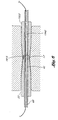
- the male connector 17 on the guide member placement device 10 of Figures 1, 2 and 4 engages the female connector 1915 on the guide member placement device 1910 of Figures 3 and 5 and attaches the two guide member placement devices 10, 1910 together such that the lumens 42, 1942 of the blunt dissectors 32, 1932 of each of the two devices are in fluid communication with one another.
- the male connector 17 disengages from the female connector 1915, permitting the two guide member placement devices 10, 1910 to be separated.
- complementary engaging members 28, 1928 of the embodiments shown in Figures 1-5 are male and female connectors, those skilled in the art will appreciate that a number of alternative configurations can be employed for the engaging members.
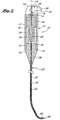
- Figure 2 is a cross-sectional view showing the internal structure of the guide member placement device to having a male connector at the distal end of the shaft.
- the internal structure of the embodiment of the guide member placement device 1910 having a female connector at the end of the shaft is similar to that shown in Figure 2. Thus, the internal structure will only be described with respect to the device having a male connector.
- the handle 12 has a proximal end wall 14 and a distal end wall 16.
- the support 20 as illustrated is provided with a generally cylindrical proximal section 24 for engagement within the distal end of the handle 12 and a tapered distal section 26 for securing the shaft.
- the shaft 22 is preferably no more than about 0.1 inches (2.5 mm) in diameter and is provided with at least one central lumen 30 for acceptance of an axially movable blunt dissector 32.
- the blunt dissector 32 is mounted within the handle 12 and extends through the support 20 and the shaft 22.
- the blunt dissector 32 is preferably provided at its proximal end with a relatively large diameter body portion 34 adapted for reciprocal motion within tubular handle 12.
- Body portion 34 is preferably provided with a slightly smaller diameter recessed portion 36 for receiving a return spring 38 which biases the blunt dissector 32 in the proximal direction and has a lumen 40 extending therethrough which is in fluid communication with the lumen 42 of the narrow portion of the blunt dissector.
- any of a variety of well known means can be utilized to provide a proximal bias on the blunt dissector 32.
- the length of body portion 34 is less than the axial length of the cavity within handle portion so that the body portion 34 has an axial range of motion within the range of from about 2 mm to about 10 mm, and preferably about .12 inch (3 mm).
- the proximal end wall 44 of the support 20 which extends into the handle 12 acts as one limiting stop for distal travel of body portion 34.
- the distal surface of the end wall 14 of the handle limits proximal travel of body portion 34.
- Spring 38 pushes against an annular shoulder 46 on body portion 34, biasing the blunt dissector 32 proximally.
- blunt dissector 32 is provided with a blunt dissection tip 48 having a lumen therethrough.
- Spring 38 normally biases the blunt dissector 32 towards a first retracted position within the distal end of shaft 22 such that the blunt dissection tip 48 does not extend from the shaft 22.
- Axial distal force on body portion 34 extends the blunt dissection tip 48 into a second position in which it extends from the shaft 22.
- the blunt dissection tip 48 may be extended and retracted in any number of ways, such as by use of a knob or button, it is preferred that a rotatable cam 50 be used.
- the cam 50 is attached to a post 54 extending proximally from the handle 12 and having a lumen 18 therein which is in fluid communication with the lumen 40 in the recessed position of the blunt dissector and the lumen 42 in the narrow portion of the blunt dissector.
- the cam 50 is rotatably mounted about a pin 56 which extends along an axis perpendicular to the longitudinal axis of the shaft 22.
- the proximal end of the body portion has a rod 19 which extends proximally through an opening in the proximal end wall 14 of the handle.
- the cam 50 has at least a two position engaging surface which, when rotated into position, engages the rod 19 of the body portion. In a first position, the cam 50 is biased by the return spring 38 to a position in which the blunt dissection tip 48 is fully retracted within the shaft 22. In a second position, the bias imposed by return spring 38 is overcome and engaging surface of the cam 50 engages the rod 19 such that the blunt dissection tip 48 is extended outwardly from the shaft 22.
- the cam 50 is preferably provided with an actuator portion 58 which extends radially outwardly and which may be used by the operator for rotating the cam.
- this instrument be manufactured from a sterilizable material having sufficient rigidity for its intended purpose.
- Many acceptable materials are well known in the art, such as stainless steel for the shaft 22, and stainless steel or a plastic for the handle portion 12.
- the guide member placement device may be made in a disposable form.
- the components preferably are made of a suitable thermoplastic.
- the thermoplastic Cycolac 2679F made by General Electric Plastics has been found suitable, which is Acrylonitrile Butadiene Styrene (ABS).
- ABS Acrylonitrile Butadiene Styrene
- the shaft 22, blunt dissector 32, and return spring 38 are made of stainless steel.
- guide member placement devices of Figures 1-7D in a representative bladder neck stabilization procedure employing a sling is described below and depicted in Figures B-14.
- the guide member placement device may also be used in a number of other surgical procedures requiring introduction of a guide member.
- a Foley catheter is placed in the bladder to identify the bladder neck.
- the guide member placement device is percutaneously inserted into the body. For example, a pair of approximately 2.5 cm (one inch) suprapubic incisions 60 and 61, shown schematically in Figure 9, may be made over the pubic tubercles and dissection may be carried down to the area of the rectus fascia.
- a first guide member placement device 10 is placed within one of the incisions and advanced along the back side of the pubic bone so that the distal tip of the shaft 22 is in contact with the bone/fascial surface to decrease the risk of puncturing the bladder.
- the cam 50 is pressed to extend the blunt dissection tip 48 from the distal end of the shaft 22, thereby creating an opening in the body tissue 62 as shown in Figures 8 and 11.
- the cam 50 is then released, retracting the blunt dissection tip 48 into the shaft 22, and the device 10 is advanced through the opening in the body tissue. This process results in the creation of a first opening in the body tissue.
- the first guide member placement device 10 is advanced until it is positioned under the urethra 64 within the tissue 62 tying between the urethra 64 and the upper vaginal wall 66 as shown in Figure 9.
- the blunt dissection tip 48 is extended and retracted during advancement of the guide member placement device 10 so as to create an opening in the tissue. Advancement of the guide member placement 10 device with extension and retraction of the blunt dissection tip 48 is continued until the distal end of the shaft 22 is positioned approximately midline to the urethra 64 as shown in Figure 10 such that the distal end of the shaft 22 extends transversely between the urethra 64 and the upper vaginal wall 66 in the plane defined by the longitudinal axes of the urethra and the vagina.
- a pocket or opening in the tissue between the urethra and the vagina may be created beneath the bladder neck prior to insertion of the first guide member placement device.
- the first guide member placement device 10 is advanced such that the distal end of the shaft is in the pocket or opening and the device is positioned as described above.
- the elastic upper vaginal wall tents As the guide member placement device 10 is advanced, the elastic upper vaginal wall tents. This tenting can be utilized to determine the position of the guide member placement device 10. The guide member placement device is advanced until tenting is apparent at the desired location.
- the above process is repeated with a second guide member placement device 1910 as shown in Figure 12.
- the second guide member placement device 1910 has an engaging member 1928 complementary to that of the first guide member placement device 10 as shown in Figure 6.
- the blunt dissection tip 1948 of the second guide member placement device 1910 is extended and retracted to create a second opening in the body tissue as described above and shown in Figure 11.
- the second guide member placement device 1910 is advanced to a position approximately midline to the urethra 64 such that the distal end of the shaft 1922 extends transversely between the urethra 64 and the upper vaginal wall 66 in the plane defined by the longitudinal axes of the urethra and the vagina.
- the second guide member placement device is advanced into the pocket or opening.
- the second guide member placement device 1910 is then aligned with the first guide member placement device 10.
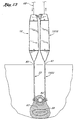
- the first and second guide member placement devices 10 and 1910 are than joined through their engaging members 28, 1928, creating a continuous opening in the tissue 62 between the urethra 64 and the upper vaginal wall 66, as shown in Figure 13.
- the two handles may also be coupled together and secured to one another.
- the lumens 42, 1942 of the blunt dissectors are in fluid communication with one another, as shown in Figure 6.
- a guide member 68 is then inserted into the lumen 18 in the handle 12 of the first guide member placement device 10 and advanced through the lumens 40, 1940. 42, 1942 of the blunt dissectors of the first and second guide member placement devices 10, 1910 until it exits from the handle 1912 of the second guide member placement device.
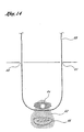
- the engaging members 28, 1928 of the two guide member placement devices 10, 1910 are then disengaged from one another and the devices 10, 1910 are removed from the patient's body, leaving the guide member 68 in place, as shown in Figure 14.
- the guide member 6B may then be used to introduce a sling attached to a sling application catheter in order to stabilize the bladder neck or stabilize the urethral floor.
- the guide member placement device may be inserted to a pre.formed opening in the tissue between the urethra and the upper vaginal wall.
- the pre-formed opening may be created by hydrodissection or with balloon catheters. Howewer, if desired the method can be practiced with guide member placement devices having a blunt dissector which is fixed in a position in which it is extended from the shaft.
- the guide member placement device may also be advanced through a trocar into the tissue between the urethra and the upper vaginal wall In another embodiment, the guide member placement device may be viewed laparoscopically during the procedure to ensure proper positioning and assist in the alignment of the first and second guide member placement devices.
Abstract
Description
- The present invention relates to a guide member placement device.
- Urinary incontinence is a widespread problem in the United States and throughout the world. Urinary incontinence affects people of all ages and can severely impact a patient both physiologically and psychologically.
- In approximately 30% of the women suffering from urinary incontinence, incontinence is caused by intrinsic sphincter deficiency (ISD). a condition in which the valves of the urethral sphincter do not properly coapt. In approximately another 30% of incontinent women, incontinence is caused by hypermobility, a condition in which the muscles around the bladder relax, causing the bladder neck and proximal urethra to rotate and descend in response to increases in intraabdominal pressure. Hypermobility may be the result of pregnancy or other conditions which weaken the muscles. In an additional group of women with urinary incontinence, the condition is caused by a combination of ISD and hypermobitity.
- In addition to the conditions described above, urinary incontinence has a number of other causes, including birth defects, disease, injury, aging, and urinary tract infection.
- Numerous approaches for treating urinary incontinence are available. For example, several procedures for stabilizing and/or slightly compressing the urethra so as to prevent the leakage of urine have been developed. The stabilizing or compressive force may be applied directly by sutures passing through the soft tissue surrounding the urethra or, alternatively, may be applied by means of a sling located under the urethra and suspended by sutures. The sutures may be anchored to the pubic bone by means of bone anchors or, alternatively, the sutures may be attached to other structures such as fascia.
- A device for dissecting around a tubular structure such as the urethra or the bladder neck is available from Lone Star Medical Products. The Lone Star device has two shafts which can be positioned in the tissue between the urethra and the vaginal wall using cystoscopy, vaginal or rectal examination, or an examination of the position of the instrument around the urethra with the bladder opened. The two shafts can be locked together to pinch the intervening tissue. A sharp blade is inserted into one of the shafts and advanced into the second shaft, cutting the tissue in between the two shafts. The cut in the tissue can be expanded using a right angle clamp and an artificial sphincter guided by a suture attached to the cutting blade of the device can be introduced into the expanded cut.
- With the Lone Star device, the distance between the two shafts cannot be gradually adjusted, In addition, the ends of the shafts of the Lone Star device come in direct contact with the tissue or bone while being advanced towards the tissue between the urethra and the upper vaginal wall. The shafts of the Lone Star device are flat at their distal ends.
- Thus, there is a need for devices which simplify treatments for urinary incontinence and increase their safety. Sling application devices for treating urinary incontinence which reduce the risk of inadvertent pinching of the urethra and undesirable scoring of tissue or bone during advancement of the device would be particularly desirable. It is also desirable to have a sling application device that does not employ a guiding suture and can create or maintain an opening in the tissue between the urethra and the upper vaginal wall without the use of a right angle clamp, thereby simplifying the procedure.
- U.S. Patent No. 5,611,515, issued March 18, 1997 to Benderev at al., introduces pioneering minimally invasive percutaneous and transvaginal bladder neck stabilization approaches. The percutaneous approach of Benderev et al. involves stabilizing the bladder neck using a bone anchor which is percutaneously introduced from the abdominal side of the patient. The transvaginal approach of Benderev et al. involves stabilizing the bladder neck using a staple or bone anchor which is transvaginally placed into the pubic bone. There is also a need for further devices and methods for improving or maintaining urinary continence involving stabilization or compression of the bladder neck or urethra, particularly devices and methods of the present invention that are less invasive than many of those currently available.
- The European patent application EP 0 654 247 discloses an endoscopic surgery device including a handle and a sleeve member for slidably receiving an obturator. The
obturator 24 includes a generally smooth shaft with a blunt-tapered distal end protruding from an end of the sleeve member. The obturator can be configured with either a bill-shaped dissector tip or a blunt tip at the distal end for separating tissue. - The present invention provides a guide member placement device for inserting a guide member in a body tissue as defined in claim 1. The guide member placement device comprises a shaft having a proximal end, a distal end, and a lumen extending therethrough. The lumen of the shaft is adapted for receiving a guidemember. The distal end of the shaft has an engaging member for engaging another guide member placement device. The device further comprises a blunt dissection tip at the distal end of the shaft and a handle with a lumen extending therethrough wherein the lumen of the shaft and the lumen of the handle are aligned. The blunt dissection tip is on a blunt dissector within the shaft and is extendable from and retractable in the shaft. The guide member placement device is adapted for use in urethral floor reconstruction procedures. The guide member placement device may also be adapted for use in bladder neck stabilization procedures. In one embodiment of the guide member placement device, the engaging member comprises a male connector. In another embodiment of the guide member placement device, the engaging member comprises a female connector. In yet another embodiment of the guidemember placement device, the shaft has a straight proximal section, a bent intermediate section and a distal end oriented at an angle of approximately 90 degrees relative to the proximal section. In another embodiment, the guide member placement device further comprises a guide member removably positioned in the lumen of the shaft. In one aspect of this embodiment, the guide member comprises a guide wire. In another aspect of this embodiment, the guide member comprises a suture.
- The present placement device can be used in a method of inserting a guide member into a body tissue. A shaft of a first guide member placement device is inserted percutaneously and advanced through the body tissue to a central point through which the guide member will pass. A shaft of a second guide member placement device is inserted percutaneously and advanced through the body tissue to the central point through which the guide member will pass. An engaging member on a distal end of the shaft of the first guide member placement device is coupled to an engaging member on a distal end of a shaft of a second guide member placement device such that a lumen in the shaft of the first guide member placement device is fluid communication with a lumen in the shaft of the second guide member placement device. A guide member is passed through the lumens of the coupled shafts of the first guide member placement device and the second guide member placement device. The shaft of the first guide member placement device and the shaft of the second guide member placement device are removed from the body, thereby leaving the guide member in the body tissue.
-
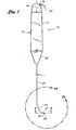
- Figure 1 is a side view of an embodiment of a guide member placement device having a male connector at the distal end of the shaft.
- Figure 2 is an assembled cross-sectional view of the guide member placement device of Figure 1 showing the internal structure of the device.
- Figure 3 is a side view of an embodiment of a guide member placement device having a female connector at the distal end of the shaft.
- Figure 4 is an enlarged cross-sectional view taken along
line 44 of the distal end of the shaft of a guide member placement device of Figure 1. - Figure 5 is an enlarged cross-sectional view taken along line 5.5 of the distal end of the shaft of the guide member placement device of Figure 3.
- Figure 6 is a cross sectional view showing the distal ends of the shafts of the guide member placement devices of Figures 1 and 3 coupled through their male and female connectors.
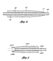
- Figure 7A is an enlarged view of the distal portion of the shaft of the guide member placement device taken
along
line 7A-7A of Figure 1. - Figure 78 is an enlarged view of the distal portion of the shaft of the guide member placement device taken
along
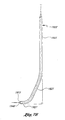
line 7B-7B of Figure 3. - Figure 7C is an enlarged view of the distal portion of the shaft of a guide member placement device having an alternate shaft configuration in which the curve is smoothly curved.
- Figure 7D is an enlarged view of the distal end of the shaft of a guide member placement device having an alternate shaft configuration in which the curve is smoothly curved.
- Figure 8 shows the blunt dissection tip extending into a tissue from the distal end of the shaft of a guide member placement device having a male connector to create an opening in the tissue.
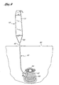
- Figure 9 shows a first guide member placement device that has been inserted into a first suprapubic incision and advanced into the body tissue.
- Figure 10 shows a guide member placement device that has been advanced into the tissue between the urethra and the upper vaginal wall such that the distal end of the shaft extends transversely between the urethra and the upper vaginal wall in the plane defined by the longitudinal axes of the urethra and the vagina.
- Figure 11 shows the blunt dissection tip extending into a tissue from the distal end of the shaft of a guide member placement device having a female connector to create an opening in the tissue.
- Figure 12 shows a second guide member placement device that has been inserted into a second suprapubic incision and advanced into a body tissue.
- Figure 13 shows the first and second guide member placement devices in the tissue between the urethra and the upper vaginal wall with the distal ends of their shafts connected to one another.
- Figure 14 shows a guide member extending between the two suprapubic incisions after removal of the first and second guide member placement devices.
-
- The device of the present invention may be used in a wide variety of medical procedures, but are particularly well suited for urethral floor reconstruction procedures such as bladder neck stabilization or suspension procedures in which a sting is used to maintain or improve urinary continence by stabilizing and/or slightly compressing the urethra or by creating a non-moveable pelvic floor. Slings suitable for use in bladder neck stabilization procedures and methods for implanting them are disclosed in U.S. Provisional Patent US-A 6 042 534.
- The present invention is particularly well suited for bladder neck stabilization procedures for treating urinary incontinence in females. The bladder neck stabilization procedures for which the present invention is especially well suited involve the creation of an opening or pocket in the tissue between the urethra and the upper vaginal wall, which is called the hiatus. The sling is then inserted in the opening or pocket. Sutures or integral attachment members at the ends of the sling are attached to the pubic bone or surrounding tissue and the tension is adjusted to slightly compress or stabilize the urethra by providing a platform to reduce distension resulting from internal pressures, thereby maintaining or improving urinary continence. Suitable methods and devices for adjusting the tension on the sutures are disclosed in U.S. Patent No. 5,611,515, issued March 18, 1997 to Benderev et al.
- Devices and methods for using a guide member to introduce a sting in the tissue between the urethra and the upper vaginal wall will now be discussed in greater detail.
- One embodiment of the present invention relates to guide member placement devices for applying a guide member under the urethra in a less invasive manner without puncturing the vaginal wall
- In general, the guide member placement device comprises a shaft having a proximal end, a distal end, and a lumen extending therethrough. The lumen is adapted for receiving a guide member.
- The shaft is rigid. The proximal end of the shaft is attached to a handle having a lumen extending therethrough. The guide member placement device has a blunt dissection tip with a lumen extending therethrough. The blunt dissection tip is located at the distal end of the shaft. The blunt dissection tip is on a blunt dissector which is within the shaft and is extendable from and retractable in the shaft.
- The lumen in the blunt dissector is in fluid communication with the lumen in the handle. The blunt dissector is axially movable and can be extended from and retracted in the shaft. Preferably, the blunt dissector is made of rigid plastic or flexible metal. For example, the blunt dissector may be a coil of stainless steal The blunt dissector may be solid and may be made of metals such as stainless steel, spring steel, Elgiloy, Nitinol, or other generally elastic metals. The blunt dissector may also be a rigid plastic such as nylon or Acrylonitrile Butadiene Styrene (ABS).
- The guide member placement device preferably has an engaging member at the distal end of the shaft which is complementary to or otherwise adapted to be attached to an engaging member at the distal end of the shaft of a second guide member placement device, such that the shafts of the two guide member placement devices can be attached to one another with the lumens of the blunt dissectors in each shaft in fluid communication with one another.
- Referring to Figures 1, 2 and 3, there are disclosed guide
member placement devices Handle Handle tubular body handle - A
support handle 12. 1912 to provide a mounting support for theshaft support handle shaft - The
shaft 22. 1922 is an elongate member with its proximal end inserted within or secured to thesupport shaft support - The
shaft support - The
shaft lumen 30 extending therethrough. A preferred embodiment of the distal end of the shaft is shown in Figures 7A and 7B. In this embodiment, theshaft proximal section intermediate section distal end shaft blunt dissector 32 within the shaft. - As will be understood by one of skill in the art, the dimensions and curvature of the
shaft - The distal ends 27, 1927 of the
shafts member placement devices members shafts member placement devices member placement device 10, depicted in Figures 1 and 2, the engaging member comprises. amale connector 17 as illustrated in the enlarged cross-sectional view of Figure 4. Themale connector 17 on the guidemember placement device 10 shown in Figures 1 and 2 is complementary to thefemale connector 1915 on the guidemember placement device 1910 shown in Figure 3 and shown in the enlarged cross-sectional view in Figure 5. As shown in the enlarged cross-sectional view of Figure 6, themale connector 17 on the guidemember placement device 10 of Figures 1, 2 and 4 engages thefemale connector 1915 on the guidemember placement device 1910 of Figures 3 and 5 and attaches the two guidemember placement devices lumens blunt dissectors male connector 17 disengages from thefemale connector 1915, permitting the two guidemember placement devices - While the complementary engaging
members - Figure 2 is a cross-sectional view showing the internal structure of the guide member placement device to having a male connector at the distal end of the shaft. The internal structure of the embodiment of the guide
member placement device 1910 having a female connector at the end of the shaft is similar to that shown in Figure 2. Thus, the internal structure will only be described with respect to the device having a male connector. - As shown in Figure 2. the
handle 12 has aproximal end wall 14 and adistal end wall 16. Thesupport 20 as illustrated is provided with a generally cylindricalproximal section 24 for engagement within the distal end of thehandle 12 and a tapereddistal section 26 for securing the shaft. - The
shaft 22 is preferably no more than about 0.1 inches (2.5 mm) in diameter and is provided with at least onecentral lumen 30 for acceptance of an axially movableblunt dissector 32. Theblunt dissector 32 is mounted within thehandle 12 and extends through thesupport 20 and theshaft 22. Theblunt dissector 32 is preferably provided at its proximal end with a relatively largediameter body portion 34 adapted for reciprocal motion withintubular handle 12.Body portion 34 is preferably provided with a slightly smaller diameter recessedportion 36 for receiving areturn spring 38 which biases theblunt dissector 32 in the proximal direction and has alumen 40 extending therethrough which is in fluid communication with thelumen 42 of the narrow portion of the blunt dissector. Alternatively, any of a variety of well known means can be utilized to provide a proximal bias on theblunt dissector 32. - The length of
body portion 34 is less than the axial length of the cavity within handle portion so that thebody portion 34 has an axial range of motion within the range of from about 2 mm to about 10 mm, and preferably about .12 inch (3 mm). Theproximal end wall 44 of thesupport 20 which extends into thehandle 12 acts as one limiting stop for distal travel ofbody portion 34. The distal surface of theend wall 14 of the handle limits proximal travel ofbody portion 34.Spring 38 pushes against an annular shoulder 46 onbody portion 34, biasing theblunt dissector 32 proximally. - The distal end of
blunt dissector 32 is provided with ablunt dissection tip 48 having a lumen therethrough.Spring 38 normally biases theblunt dissector 32 towards a first retracted position within the distal end ofshaft 22 such that theblunt dissection tip 48 does not extend from theshaft 22. Axial distal force onbody portion 34 extends theblunt dissection tip 48 into a second position in which it extends from theshaft 22. Although theblunt dissection tip 48 may be extended and retracted in any number of ways, such as by use of a knob or button, it is preferred that arotatable cam 50 be used. - The
cam 50 is attached to apost 54 extending proximally from thehandle 12 and having alumen 18 therein which is in fluid communication with thelumen 40 in the recessed position of the blunt dissector and thelumen 42 in the narrow portion of the blunt dissector. Thecam 50 is rotatably mounted about apin 56 which extends along an axis perpendicular to the longitudinal axis of theshaft 22. The proximal end of the body portion has arod 19 which extends proximally through an opening in theproximal end wall 14 of the handle. - The
cam 50 has at least a two position engaging surface which, when rotated into position, engages therod 19 of the body portion. In a first position, thecam 50 is biased by thereturn spring 38 to a position in which theblunt dissection tip 48 is fully retracted within theshaft 22. In a second position, the bias imposed byreturn spring 38 is overcome and engaging surface of thecam 50 engages therod 19 such that theblunt dissection tip 48 is extended outwardly from theshaft 22. Thecam 50 is preferably provided with anactuator portion 58 which extends radially outwardly and which may be used by the operator for rotating the cam. - It is preferred that this instrument be manufactured from a sterilizable material having sufficient rigidity for its intended purpose. Many acceptable materials are well known in the art, such as stainless steel for the
shaft 22, and stainless steel or a plastic for thehandle portion 12. - Alternatively, the guide member placement device may be made in a disposable form. In this embodiment, the components preferably are made of a suitable thermoplastic. In particular, the thermoplastic Cycolac 2679F made by General Electric Plastics has been found suitable, which is Acrylonitrile Butadiene Styrene (ABS). Preferably, the
shaft 22,blunt dissector 32, and returnspring 38 are made of stainless steel. - The use of the guide member placement devices of Figures 1-7D in a representative bladder neck stabilization procedure employing a sling is described below and depicted in Figures B-14. However, those skilled in the art will appreciate that the guide member placement device may also be used in a number of other surgical procedures requiring introduction of a guide member.
- The following procedure is intended to place a guide member in the tissue between the urethra and the vaginal wall without puncturing the vaginal wall A Foley catheter is placed in the bladder to identify the bladder neck. The guide member placement device is percutaneously inserted into the body. For example, a pair of approximately 2.5 cm (one inch)
suprapubic incisions member placement device 10 is placed within one of the incisions and advanced along the back side of the pubic bone so that the distal tip of theshaft 22 is in contact with the bone/fascial surface to decrease the risk of puncturing the bladder. As resistance is felt, thecam 50 is pressed to extend theblunt dissection tip 48 from the distal end of theshaft 22, thereby creating an opening in thebody tissue 62 as shown in Figures 8 and 11. Thecam 50 is then released, retracting theblunt dissection tip 48 into theshaft 22, and thedevice 10 is advanced through the opening in the body tissue. This process results in the creation of a first opening in the body tissue. - The first guide
member placement device 10 is advanced until it is positioned under theurethra 64 within thetissue 62 tying between the urethra 64 and the uppervaginal wall 66 as shown in Figure 9. Theblunt dissection tip 48 is extended and retracted during advancement of the guidemember placement device 10 so as to create an opening in the tissue. Advancement of theguide member placement 10 device with extension and retraction of theblunt dissection tip 48 is continued until the distal end of theshaft 22 is positioned approximately midline to the urethra 64 as shown in Figure 10 such that the distal end of theshaft 22 extends transversely between the urethra 64 and the uppervaginal wall 66 in the plane defined by the longitudinal axes of the urethra and the vagina. - Alternatively, a pocket or opening in the tissue between the urethra and the vagina may be created beneath the bladder neck prior to insertion of the first guide member placement device. The first guide
member placement device 10 is advanced such that the distal end of the shaft is in the pocket or opening and the device is positioned as described above. - As the guide
member placement device 10 is advanced, the elastic upper vaginal wall tents. This tenting can be utilized to determine the position of the guidemember placement device 10. The guide member placement device is advanced until tenting is apparent at the desired location. - The above process is repeated with a second guide
member placement device 1910 as shown in Figure 12. The second guidemember placement device 1910 has an engagingmember 1928 complementary to that of the first guidemember placement device 10 as shown in Figure 6. Theblunt dissection tip 1948 of the second guidemember placement device 1910 is extended and retracted to create a second opening in the body tissue as described above and shown in Figure 11. - The second guide
member placement device 1910 is advanced to a position approximately midline to the urethra 64 such that the distal end of theshaft 1922 extends transversely between the urethra 64 and the uppervaginal wall 66 in the plane defined by the longitudinal axes of the urethra and the vagina. - Alternatively, when the pocket or opening in the tissue between the urethra and the vagina is created prior to insertion of the first guide member placement device, the second guide member placement device is advanced into the pocket or opening.
- The second guide
member placement device 1910 is then aligned with the first guidemember placement device 10. - The first and second guide
member placement devices members tissue 62 between the urethra 64 and the uppervaginal wall 66, as shown in Figure 13. In addition to joining the two shafts, the two handles may also be coupled together and secured to one another. - After joining of the two guide
member placement devices lumens guide member 68 is then inserted into thelumen 18 in thehandle 12 of the first guidemember placement device 10 and advanced through thelumens 40, 1940. 42, 1942 of the blunt dissectors of the first and second guidemember placement devices handle 1912 of the second guide member placement device. - The engaging
members member placement devices devices guide member 68 in place, as shown in Figure 14. - The guide member 6B may then be used to introduce a sling attached to a sling application catheter in order to stabilize the bladder neck or stabilize the urethral floor.
- Rather than using the
blunt dissection tips 48 of the guide member placement devices to create the continuous opening in the tissue, the guide member placement device may be inserted to a pre.formed opening in the tissue between the urethra and the upper vaginal wall. The pre-formed opening may be created by hydrodissection or with balloon catheters. Howewer, if desired the method can be practiced with guide member placement devices having a blunt dissector which is fixed in a position in which it is extended from the shaft. - The guide member placement device may also be advanced through a trocar into the tissue between the urethra and the upper vaginal wall In another embodiment, the guide member placement device may be viewed laparoscopically during the procedure to ensure proper positioning and assist in the alignment of the first and second guide member placement devices.
Claims (18)
- A guide member placement device for inserting a guide member into a body tissue, comprising:characterized by a spring (38) for biasing the blunt dissector (32) towards a retracted position such that the blunt dissection tip (48) does not extend from the shaft (22); anda handle (12) including a distal end (16), a proximal end (14), and a lumen (40) extending therethrough;a rigid shaft (22) including a proximal end, a distal end (27), and a lumen (30) extending therethrough, the proximal end of the shaft (22) being attached to the distal end (16) of the handle (12) such that the lumens extending through the handle (12) and the shaft (22) are aligned;a blunt dissector (32) disposed within the lumen (30) of the shaft (22) and within the handle, the blunt dissector including a proximal end, a distal end, and a lumen (42) for receiving a guide member (68) extending therethrough;an axially-movable blunt dissection tip (48) with a lumen extending therethrough, the blunt dissection tip (48) being positioned on the distal end of the blunt dissector (32) and being extendable from and retractable into the lumen (30) of the shaft (22), wherein the lumen of the blunt dissection tip (48) and the lumen of the blunt dissector (32) are in fluid communication;
an actuator portion (58) including a cam (50) adapted to place axial distal force upon the blunt dissector (32) to thereby place the blunt dissection tip (48) in an extended position, where the blunt dissection tip (48) extends from the shaft (22), said spring (38) and actuator portion (58) being associated with the handle (12). - The guide member placement device of claim 1, further comprising an engaging member (28) disposed at the distal end of the shaft (22), wherein the engaging member (28) is complementary to an engaging member (1928) disposed at the distal end (1927) of the shaft (1922) of a second guide member placement device (1910), such that the shafts of each guide member placement device can be attached to one another with the lumens of the blunt dissectors (32, 1932) in each guide member placement device in fluid communication.
- The guide member placement device of claim 2, wherein the engaging member (28) comprises a male connector adapted to be releasably coupled to the engaging member (1928) comprising a female connector on a second guide member device (1910).
- The guide member placement device of claim 2, wherein the engaging member (28) comprises a female connector adapted to be releasably coupled to a male connector on a second guide member device (1910).
- The guide member placement device of any one of the claims 1 to 4, wherein the shaft (22) includes a straight proximal section (23), a bent intermediate section (25) and a distal end (27), the distal end (27) being oriented at an angle of approximately 90 degrees relative to the proximal section (23).
- The guide member placement device of any one of the claims 1 to 5, further comprising a guide member (18, 68) removably positioned in the lumen (42) of the blunt dissector (32).
- The guide member placement device of claim 6, wherein the guide member ( 18, 68) comprises a guidewire.
- The guide member placement device of claim 6, wherein the guide member (18, 68) comprises a suture.
- The guide member placement device of any one of the claims 1 to 8, wherein the blunt dissector (32) comprises an elastic metal material.
- The guide member placement device of any one of the claims 1 to 9, wherein at least part of the exterior surface of the handle (12) is textured to produce a high-friction gripping surface.
- The guide member placement device of any one of the claims 1 to 10, wherein the handle (12) comprises a gripping area and a mounting support (20) for the shaft (22).
- The guide member placement device of claim 11, wherein the gripping area comprising a hollow tubular body (24) including a proximal endwall (14) and a distal endwall ( 16).
- The guide member placement device of claim 11, wherein the mounting support (20) includes a distal end and a proximal end, and the proximal end of the mounting support (20) extends into the hollow tubular body (24) of the handle (12).
- The guide member placement device of claim 1, wherein the distal end (27) of the shaft (22) is oriented at an angle of approximately 90° relative to a straight proximal section (23) of the shaft (22).
- The guide member placement device of any one of the claims 1 to 14, wherein the blunt dissector (32) comprises a body portion (34) including a recessed portion (36), the recess portion being adapted for receiving the spring (38).
- The guide member placement device of claim 15, wherein the body portion (34) of the blunt dissector (32) has an axial range of motion from 2 mm to 10 mm.
- The guide member placement device of claim 15 or 16, wherein the mounting support (20) includes a proximal endwall (44) which limits the distal travel of the body portion (34) of the blunt dissector (32).
- The guide member placement device of claim 15 or 16, wherein the handle (12) includes a proximal endwall (14) which limits the proximal travel of the body portion (34) of the blunt dissector (32).
Priority Applications (1)
| Application Number | Priority Date | Filing Date | Title |
|---|---|---|---|
| EP03029756.8A EP1402822B1 (en) | 1997-02-13 | 1998-02-13 | Percutaneous and hiatal devices for use in minimally invasive pelvic surgery |
Applications Claiming Priority (3)
| Application Number | Priority Date | Filing Date | Title |
|---|---|---|---|
| US3817197P | 1997-02-13 | 1997-02-13 | |
| US38171P | 1997-02-13 | ||
| PCT/US1998/003065 WO1998035616A1 (en) | 1997-02-13 | 1998-02-13 | Percutaneous and hiatal devices and methods for use in minimally invasive pelvic surgery |
Related Child Applications (1)
| Application Number | Title | Priority Date | Filing Date |
|---|---|---|---|
| EP03029756.8A Division EP1402822B1 (en) | 1997-02-13 | 1998-02-13 | Percutaneous and hiatal devices for use in minimally invasive pelvic surgery |
Publications (3)
| Publication Number | Publication Date |
|---|---|
| EP1017321A1 EP1017321A1 (en) | 2000-07-12 |
| EP1017321A4 EP1017321A4 (en) | 2001-04-11 |
| EP1017321B1 true EP1017321B1 (en) | 2004-01-14 |
Family
ID=21898455
Family Applications (1)
| Application Number | Title | Priority Date | Filing Date |
|---|---|---|---|
| EP98907503A Expired - Lifetime EP1017321B1 (en) | 1997-02-13 | 1998-02-13 | Percutaneous and hiatal devices for use in minimally invasive pelvic surgery |
Country Status (7)
| Country | Link |
|---|---|
| US (17) | US6423080B1 (en) |
| EP (1) | EP1017321B1 (en) |
| JP (3) | JP4023560B2 (en) |
| AU (1) | AU6329498A (en) |
| CA (1) | CA2280812A1 (en) |
| DE (1) | DE69821127T2 (en) |
| WO (1) | WO1998035616A1 (en) |
Families Citing this family (335)
| Publication number | Priority date | Publication date | Assignee | Title |
|---|---|---|---|---|
| US6423080B1 (en) * | 1997-02-13 | 2002-07-23 | Scimed Life Systems, Inc. | Percutaneous and hiatal devices and methods for use in minimally invasive pelvic surgery |
| US6599235B2 (en) | 1997-03-18 | 2003-07-29 | American Medical Systems Inc. | Transvaginal bone anchor implantation device |
| US6039686A (en) * | 1997-03-18 | 2000-03-21 | Kovac; S. Robert | System and a method for the long term cure of recurrent urinary female incontinence |
| US6419624B1 (en) * | 1999-10-11 | 2002-07-16 | Uromedica, Inc. | Apparatus and method for inserting an adjustable implantable genitourinary device |
| US6579224B1 (en) * | 1999-10-11 | 2003-06-17 | Uromedica, Inc. | Apparatus and method for inserting an adjustable implantable genitourinary device |
| US7364540B1 (en) | 1997-06-12 | 2008-04-29 | Uromedica, Inc. | Implantable device and method for adjustably restricting a body lumen |
| US6382214B1 (en) | 1998-04-24 | 2002-05-07 | American Medical Systems, Inc. | Methods and apparatus for correction of urinary and gynecological pathologies including treatment of male incontinence and female cystocele |
| WO2000040158A2 (en) | 1999-01-08 | 2000-07-13 | Influence Medical Technologies, Ltd. | Surgical tack |
| US20050283189A1 (en) * | 1999-03-31 | 2005-12-22 | Rosenblatt Peter L | Systems and methods for soft tissue reconstruction |
| AU4684500A (en) | 1999-04-30 | 2000-11-17 | Uromedica, Inc. | Method and apparatus for adjustable sling for treatment of urinary stress incontinence |
| AUPQ362199A0 (en) * | 1999-10-22 | 1999-11-18 | Kaladelfos, George | Intra-vaginal sling placement device |
| US6406423B1 (en) * | 2000-01-21 | 2002-06-18 | Sofradim Production | Method for surgical treatment of urinary incontinence and device for carrying out said method |
| AU2001275257A1 (en) | 2000-06-05 | 2001-12-17 | Scimed Life Systems, Inc. Et.Al. | Methods and devices for the treatment of urinary incontinence |
| US6638211B2 (en) * | 2000-07-05 | 2003-10-28 | Mentor Corporation | Method for treating urinary incontinence in women and implantable device intended to correct urinary incontinence |
| FR2811218B1 (en) | 2000-07-05 | 2003-02-28 | Patrice Suslian | IMPLANTABLE DEVICE FOR CORRECTING URINARY INCONTINENCE |
| CA2423188C (en) * | 2000-09-26 | 2010-03-30 | Ethicon, Inc. | Surgical apparatus and methods for delivery of a sling in the treatment of female urinary incontinence |
| US20060205995A1 (en) | 2000-10-12 | 2006-09-14 | Gyne Ideas Limited | Apparatus and method for treating female urinary incontinence |
| US8167785B2 (en) | 2000-10-12 | 2012-05-01 | Coloplast A/S | Urethral support system |
| GB0025068D0 (en) | 2000-10-12 | 2000-11-29 | Browning Healthcare Ltd | Apparatus and method for treating female urinary incontinence |
| US6689047B2 (en) * | 2000-11-15 | 2004-02-10 | Scimed Life Systems, Inc. | Treating urinary incontinence |
| US20020161382A1 (en) * | 2001-03-29 | 2002-10-31 | Neisz Johann J. | Implant inserted without bone anchors |
| US6641525B2 (en) | 2001-01-23 | 2003-11-04 | Ams Research Corporation | Sling assembly with secure and convenient attachment |
| US20020147382A1 (en) * | 2001-01-23 | 2002-10-10 | Neisz Johann J. | Surgical articles and methods |
| US6652450B2 (en) * | 2001-01-23 | 2003-11-25 | American Medical Systems, Inc. | Implantable article and method for treating urinary incontinence using means for repositioning the implantable article |
| US6612977B2 (en) | 2001-01-23 | 2003-09-02 | American Medical Systems Inc. | Sling delivery system and method of use |
| AU2005200516B2 (en) * | 2001-01-23 | 2006-10-26 | American Medical Systems, Inc. | Surgical articles |
| US7070556B2 (en) * | 2002-03-07 | 2006-07-04 | Ams Research Corporation | Transobturator surgical articles and methods |
| US7229453B2 (en) * | 2001-01-23 | 2007-06-12 | Ams Research Corporation | Pelvic floor implant system and method of assembly |
| US9149261B2 (en) | 2001-03-09 | 2015-10-06 | Boston Scientific Scimed, Inc. | Systems, methods and devices relating to delivery of medical implants |
| US8033983B2 (en) * | 2001-03-09 | 2011-10-11 | Boston Scientific Scimed, Inc. | Medical implant |
| US6991597B2 (en) | 2001-03-09 | 2006-01-31 | Boston Scientific Scimed, Inc. | System for implanting an implant and method thereof |
| US8915927B2 (en) | 2001-03-09 | 2014-12-23 | Boston Scientific Scimed, Inc. | Systems, methods and devices relating to delivery of medical implants |
| US20050131393A1 (en) * | 2001-03-09 | 2005-06-16 | Scimed Life Systems, Inc. | Systems, methods and devices relating to delivery of medical implants |
| GB0108088D0 (en) | 2001-03-30 | 2001-05-23 | Browning Healthcare Ltd | Surgical implant |
| US7407480B2 (en) * | 2001-07-27 | 2008-08-05 | Ams Research Corporation | Method and apparatus for correction of urinary and gynecological pathologies, including treatment of incontinence cystocele |
| US7037255B2 (en) * | 2001-07-27 | 2006-05-02 | Ams Research Corporation | Surgical instruments for addressing pelvic disorders |
| US20040073235A1 (en) * | 2001-10-01 | 2004-04-15 | Lund Robert E. | Surgical article |
| US6648921B2 (en) | 2001-10-03 | 2003-11-18 | Ams Research Corporation | Implantable article |
| US6673010B2 (en) * | 2001-10-22 | 2004-01-06 | T. A. G. Medical Products Ltd. | Biological vessel suspending assembly and systems and methods utilizing same |
| US6974462B2 (en) * | 2001-12-19 | 2005-12-13 | Boston Scientific Scimed, Inc. | Surgical anchor implantation device |
| US6911003B2 (en) * | 2002-03-07 | 2005-06-28 | Ams Research Corporation | Transobturator surgical articles and methods |
| US7454784B2 (en) * | 2002-07-09 | 2008-11-18 | Harvinder Sahota | System and method for identity verification |
| US20040010264A1 (en) * | 2002-07-15 | 2004-01-15 | Dean Acker | Cable passer for less invasive surgery |
| AU2003269934A1 (en) | 2002-08-02 | 2004-02-23 | C.R. Bard, Inc. | Self anchoring sling and introducer system |
| US7637384B2 (en) * | 2002-08-09 | 2009-12-29 | Crown Packaging Technology, Inc. | Tamper evident closure with locking band and container therefor |
| CA2495666C (en) | 2002-08-14 | 2014-05-27 | Michael S. H. Chu | Systems, methods and devices relating to delivery of medical implants |
| US6673101B1 (en) * | 2002-10-09 | 2004-01-06 | Endovascular Technologies, Inc. | Apparatus and method for deploying self-expanding stents |
| US6808486B1 (en) * | 2002-12-03 | 2004-10-26 | Pat O'Donnell | Surgical instrument for treating female urinary stress incontinence |
| US7402133B2 (en) | 2002-12-17 | 2008-07-22 | Boston Scientific Scimed, Inc. | Spacer for sling delivery system |
| US8562646B2 (en) * | 2002-12-19 | 2013-10-22 | Boston Scientific Scimed, Inc. | Anchoring to soft tissue |
| GB0307082D0 (en) | 2003-03-27 | 2003-04-30 | Gyne Ideas Ltd | Drug delivery device and method |
| US7494495B2 (en) * | 2003-03-28 | 2009-02-24 | Coloplast A/S | Method and implant for curing cystocele |
| FR2852813B1 (en) * | 2003-03-28 | 2005-06-24 | Analytic Biosurgical Solutions | INTRODUCER AND PERFORATOR GUIDE FOR THE IMPLEMENTATION OF A BANDLET IN THE HUMAN BODY |
| US8012080B2 (en) | 2003-04-25 | 2011-09-06 | Boston Scientific Scimed, Inc. | Systems and methods for sling delivery and placement |
| ITRM20030210A1 (en) * | 2003-04-30 | 2004-11-01 | Mauro Cervigni | PROSTHESIS TO BE USED IN THE PROLASSO SURGICAL THERAPY |
| US20050143690A1 (en) * | 2003-05-01 | 2005-06-30 | High Kenneth A. | Cystotomy catheter capture device and methods of using same |
| DE10321012A1 (en) * | 2003-05-12 | 2004-12-23 | Riek, Siegfried, Dr.med. | Medical instrument for treating female incontinence uses band looped round urethra with rod-like ultrasound probe with instrument channel containing displaceable draw-in aid |
| US7361138B2 (en) | 2003-07-31 | 2008-04-22 | Scimed Life Systems, Inc. | Bioabsorbable casing for surgical sling assembly |
| US8545386B2 (en) * | 2003-08-14 | 2013-10-01 | Boston Scientific Scimed, Inc. | Surgical slings |
| US8337386B2 (en) | 2003-08-14 | 2012-12-25 | Boston Scientific Scimed, Inc. | Surgical slings |
| US7347812B2 (en) | 2003-09-22 | 2008-03-25 | Ams Research Corporation | Prolapse repair |
| EP1682009B1 (en) | 2003-10-03 | 2014-03-05 | Boston Scientific Limited, an Irish company | Systems for a delivering a medical implant to an anatomical location in a patient |
| US7261723B2 (en) * | 2003-11-12 | 2007-08-28 | Ethicon, Inc. | Surgical instrument and method for the treatment of urinary incontinence |
| US7261730B2 (en) * | 2003-11-14 | 2007-08-28 | Lumerx, Inc. | Phototherapy device and system |
| EP2510884A1 (en) * | 2003-11-17 | 2012-10-17 | Boston Scientific Limited | Systems relating to associating a medical implant with a delivery device |
| US20100261951A1 (en) * | 2004-02-23 | 2010-10-14 | Uromedica, Inc. | Method and apparatus for an adjustable implantable continence device |
| US20060241339A1 (en) * | 2005-02-23 | 2006-10-26 | Cook Timothy C | Method and apparatus for an adjustable implantable continence device |
| US8425539B2 (en) | 2004-04-12 | 2013-04-23 | Xlumena, Inc. | Luminal structure anchoring devices and methods |
| US7500945B2 (en) * | 2004-04-30 | 2009-03-10 | Ams Research Corporation | Method and apparatus for treating pelvic organ prolapse |
| US7351197B2 (en) | 2004-05-07 | 2008-04-01 | Ams Research Corporation | Method and apparatus for cystocele repair |
| US7811222B2 (en) | 2004-04-30 | 2010-10-12 | Ams Research Corporation | Method and apparatus for treating pelvic organ prolapse |
| US8439820B2 (en) * | 2004-05-06 | 2013-05-14 | Boston Scientific Scimed, Inc. | Systems and methods for sling delivery and placement |
| CA2565251C (en) | 2004-05-06 | 2013-06-25 | Boston Scientific Scimed, Inc. | Systems employing a push tube for delivering a urethral sling |
| US8062206B2 (en) | 2004-05-07 | 2011-11-22 | Ams Research Corporation | Method and apparatus for treatment of vaginal anterior repairs |
| GB0411360D0 (en) | 2004-05-21 | 2004-06-23 | Mpathy Medical Devices Ltd | Implant |
| US20050278037A1 (en) * | 2004-06-11 | 2005-12-15 | Analytic Biosurgical Solutions-Abiss | Implant for the treatment of cystocele and rectocele |
| EP3087949B1 (en) | 2004-06-14 | 2018-07-25 | Boston Scientific Limited | System relating to implantable supportive slings |
| EP1799130A1 (en) * | 2004-09-14 | 2007-06-27 | Uromedica, Inc. | Implantation tool for adjustable implantable genitourinary device |
| US20080103504A1 (en) * | 2006-10-30 | 2008-05-01 | Schmitz Gregory P | Percutaneous spinal stenosis treatment |
| US8062300B2 (en) * | 2006-05-04 | 2011-11-22 | Baxano, Inc. | Tissue removal with at least partially flexible devices |
| US7857813B2 (en) | 2006-08-29 | 2010-12-28 | Baxano, Inc. | Tissue access guidewire system and method |
| US7938830B2 (en) * | 2004-10-15 | 2011-05-10 | Baxano, Inc. | Powered tissue modification devices and methods |
| US7963915B2 (en) | 2004-10-15 | 2011-06-21 | Baxano, Inc. | Devices and methods for tissue access |
| US9101386B2 (en) | 2004-10-15 | 2015-08-11 | Amendia, Inc. | Devices and methods for treating tissue |
| US8257356B2 (en) | 2004-10-15 | 2012-09-04 | Baxano, Inc. | Guidewire exchange systems to treat spinal stenosis |
| US8048080B2 (en) * | 2004-10-15 | 2011-11-01 | Baxano, Inc. | Flexible tissue rasp |
| US7738969B2 (en) | 2004-10-15 | 2010-06-15 | Baxano, Inc. | Devices and methods for selective surgical removal of tissue |
| US8221397B2 (en) | 2004-10-15 | 2012-07-17 | Baxano, Inc. | Devices and methods for tissue modification |
| US7578819B2 (en) | 2005-05-16 | 2009-08-25 | Baxano, Inc. | Spinal access and neural localization |
| US7887538B2 (en) | 2005-10-15 | 2011-02-15 | Baxano, Inc. | Methods and apparatus for tissue modification |
| US8617163B2 (en) | 2004-10-15 | 2013-12-31 | Baxano Surgical, Inc. | Methods, systems and devices for carpal tunnel release |
| US8430881B2 (en) | 2004-10-15 | 2013-04-30 | Baxano, Inc. | Mechanical tissue modification devices and methods |
| US20110190772A1 (en) | 2004-10-15 | 2011-08-04 | Vahid Saadat | Powered tissue modification devices and methods |
| US20070213734A1 (en) * | 2006-03-13 | 2007-09-13 | Bleich Jeffery L | Tissue modification barrier devices and methods |
| EP1799129B1 (en) | 2004-10-15 | 2020-11-25 | Baxano, Inc. | Devices for tissue removal |
| US20100331883A1 (en) | 2004-10-15 | 2010-12-30 | Schmitz Gregory P | Access and tissue modification systems and methods |
| US9247952B2 (en) | 2004-10-15 | 2016-02-02 | Amendia, Inc. | Devices and methods for tissue access |
| CA2585243A1 (en) * | 2004-10-25 | 2006-05-04 | Scimed Life Systems, Inc. | Systems and methods for sling delivery and placement |
| US8500624B2 (en) * | 2004-10-25 | 2013-08-06 | Boston Scientific Scimed, Inc. | Systems and methods for sling delivery and placement |
| US20060173468A1 (en) * | 2005-01-28 | 2006-08-03 | Marc Simmon | Obturator introducer with snare |
| BRPI0609970A2 (en) * | 2005-04-05 | 2011-10-11 | Ams Res Corp | pelvic implant, surgical instrument and combination |
| WO2006108145A1 (en) | 2005-04-06 | 2006-10-12 | Boston Scientific Scimed, Inc. | Systems, devices, and methods for treating pelvic floor disorders |
| US7393320B2 (en) | 2005-04-29 | 2008-07-01 | Ams Research Corporation | Pelvic floor health articles and procedures |
| WO2007002012A1 (en) | 2005-06-21 | 2007-01-04 | Ams Research Corporation | Apparatus for securing a urethral sling to pubic bone |
| WO2007002071A1 (en) | 2005-06-21 | 2007-01-04 | Ams Research Corporation | Apparatus for securing a urethral sling to pubic bone |
| ITMI20050256U1 (en) * | 2005-07-14 | 2007-01-15 | Bioengineering Lab S P A | SURGICAL INSTRUMENT FOR CARRYING OUT SUBCUTANEOUS TUNNELIZATION |
| EP3533416A1 (en) | 2005-07-25 | 2019-09-04 | Boston Scientific Limited | Pelvic floor repair system |
| CA2615130A1 (en) | 2005-07-26 | 2007-02-08 | Ams Research Corporation | Methods and systems for treatment of prolapse |
| JP2009515564A (en) | 2005-08-04 | 2009-04-16 | シー・アール・バード・インコーポレイテツド | Pelvic implant system and method |
| AU2006278522A1 (en) * | 2005-08-04 | 2007-02-15 | C.R. Bard, Inc. | Systems for introducing implants |
| US7935046B2 (en) * | 2005-08-11 | 2011-05-03 | Boston Scientific Scimed, Inc. | Systems, methods and devices relating to a removable sleeve for an implantable sling |
| WO2007027592A1 (en) * | 2005-08-29 | 2007-03-08 | Ams Research Corporation | System for positioning support mesh in a patient |
| US7878970B2 (en) * | 2005-09-28 | 2011-02-01 | Boston Scientific Scimed, Inc. | Apparatus and method for suspending a uterus |
| US8092456B2 (en) | 2005-10-15 | 2012-01-10 | Baxano, Inc. | Multiple pathways for spinal nerve root decompression from a single access point |
| US8062298B2 (en) | 2005-10-15 | 2011-11-22 | Baxano, Inc. | Flexible tissue removal devices and methods |
| US8366712B2 (en) | 2005-10-15 | 2013-02-05 | Baxano, Inc. | Multiple pathways for spinal nerve root decompression from a single access point |
| US7914578B2 (en) | 2005-10-24 | 2011-03-29 | Gil Vardi | Method and apparatus for expanding tissue |
| EP1948073B1 (en) | 2005-11-14 | 2014-03-19 | C.R.Bard, Inc. | Sling anchor system |
| US7637860B2 (en) * | 2005-11-16 | 2009-12-29 | Boston Scientific Scimed, Inc. | Devices for minimally invasive pelvic surgery |
| EP1965712A4 (en) * | 2005-12-28 | 2010-05-26 | Bard Inc C R | Apparatus and method for introducing implants |
| US9144483B2 (en) | 2006-01-13 | 2015-09-29 | Boston Scientific Scimed, Inc. | Placing fixation devices |
| WO2007097994A2 (en) | 2006-02-16 | 2007-08-30 | Ams Research Corporation | Surgical articles and methods for treating pelvic conditions |
| US20070197895A1 (en) * | 2006-02-17 | 2007-08-23 | Sdgi Holdings, Inc. | Surgical instrument to assess tissue characteristics |
| JP4734651B2 (en) * | 2006-03-03 | 2011-07-27 | 国立大学法人 宮崎大学 | Surgery aid |
| US8170686B2 (en) * | 2006-03-14 | 2012-05-01 | Boston Scientific Scimed, Inc. | Heatable sling support for an anatomical location |
| US20090318752A1 (en) * | 2006-03-15 | 2009-12-24 | C. R. Bard, Inc. | Implants for the treatment of pelvic floor disorders |
| WO2007109508A1 (en) | 2006-03-16 | 2007-09-27 | Boston Scientific Limited | System and method for treating tissue wall prolapse |
| US8758405B2 (en) * | 2006-03-23 | 2014-06-24 | Ethicon Endo-Surgery, Inc | Suture tensioning device |
| US20100318098A1 (en) * | 2006-04-04 | 2010-12-16 | Lund Robert E | Systems and Methods for Implanting Medical Devices |
| US9084664B2 (en) | 2006-05-19 | 2015-07-21 | Ams Research Corporation | Method and articles for treatment of stress urinary incontinence |
| US20080009667A1 (en) * | 2006-06-08 | 2008-01-10 | Ams Research Corporation | Methods and apparatus for prolapse repair and hysterectomy |
| EP2029048A2 (en) | 2006-06-16 | 2009-03-04 | AMS Research Corporation | Surgical implants and tools for treating pelvic conditions |
| US20090259092A1 (en) * | 2006-06-22 | 2009-10-15 | Ogdahl Jason W | Adjustable Sling and Method of Treating Pelvic Conditions |
| CA2936752A1 (en) | 2006-06-22 | 2007-12-27 | Ams Research Corporation | Adjustable tension incontinence sling assemblies |
| WO2008033950A2 (en) | 2006-09-13 | 2008-03-20 | C. R. Bard, Inc. | Urethral support system |
| EP2097013B1 (en) * | 2006-10-03 | 2017-03-29 | Boston Scientific Limited | Systems and devices for treating pelvic floor disorders |
| WO2008042434A2 (en) | 2006-10-03 | 2008-04-10 | Boston Scientific Scimed, Inc. | Systems and devices for delivering an implant |
| BRPI0718156A2 (en) | 2006-10-26 | 2013-11-26 | Ams Res Corp | INSERT TOOL AND METHOD FOR PREPARING A SURGICAL TREATMENT SET. |
| US8951185B2 (en) | 2007-10-26 | 2015-02-10 | Ams Research Corporation | Surgical articles and methods for treating pelvic conditions |
| US10524816B2 (en) * | 2007-02-02 | 2020-01-07 | DePuy Synthes Products, Inc. | Tunnel tool for soft tissue |
| US8828000B2 (en) * | 2007-02-13 | 2014-09-09 | The Board Of Regents Of The University Of Texas System | Apparatus to trace and cut a tendon or other laterally extended anatomical structure |
| US20080208223A1 (en) * | 2007-02-26 | 2008-08-28 | Paul Edward Kraemer | Cable clamping device and method of its use |
| CA2628190C (en) * | 2007-04-03 | 2015-04-07 | Harbison-Fischer, Inc. | High compression downhole pump |
| US9387308B2 (en) * | 2007-04-23 | 2016-07-12 | Cardioguidance Biomedical, Llc | Guidewire with adjustable stiffness |
| JP2008284107A (en) * | 2007-05-16 | 2008-11-27 | Olympus Corp | Intracavitary insertion implement guiding instrument and intracavitary insertion implement guiding system |
| WO2008157513A1 (en) * | 2007-06-15 | 2008-12-24 | Baxano, Inc. | Devices and methods for measuring the space around a nerve root |
| JP2010533544A (en) * | 2007-07-16 | 2010-10-28 | エーエムエス リサーチ コーポレイション | Surgical instrument and method for treating pelvic disease |
| AU2008307757B2 (en) | 2007-07-26 | 2013-07-04 | Alpha Scientific Corporation | Surgical suturing device, method and tools used therewith |
| US9226748B2 (en) * | 2007-07-26 | 2016-01-05 | Alpha Scientific Corporation | Surgical suturing device, method and tools used therewith |
| US8597173B2 (en) | 2007-07-27 | 2013-12-03 | Ams Research Corporation | Pelvic floor treatments and related tools and implants |
| JP5535070B2 (en) | 2007-07-30 | 2014-07-02 | ボストン サイエンティフィック サイムド,インコーポレイテッド | Apparatus and method for treatment of stress urinary incontinence |
| WO2009032363A1 (en) | 2007-09-06 | 2009-03-12 | Baxano, Inc. | Method, system and apparatus for neural localization |
| AU2008302768B2 (en) | 2007-09-21 | 2014-01-23 | Boston Scientific Scimed, Inc. | Pelvic floor treatments and related tools and implants |
| US8382785B2 (en) * | 2007-09-27 | 2013-02-26 | Swan Valley Medical Incorporated | Apparatus and method for performing cystotomy procedures |
| US8118736B2 (en) * | 2007-09-27 | 2012-02-21 | Swan Valley Medical, Incorporated | Method of accessing a bladder and associated apparatus therefor |
| US8206280B2 (en) | 2007-11-13 | 2012-06-26 | C. R. Bard, Inc. | Adjustable tissue support member |
| WO2009075800A1 (en) * | 2007-12-07 | 2009-06-18 | Ams Research Corporation | Pelvic floor treatments and related tools and implants |
| US8192436B2 (en) | 2007-12-07 | 2012-06-05 | Baxano, Inc. | Tissue modification devices |
| US20090171141A1 (en) * | 2007-12-27 | 2009-07-02 | Chu Michael S H | Anterior Repair - Needle Path and Incision Sites |
| US9282958B2 (en) * | 2007-12-28 | 2016-03-15 | Boston Scientific Scimed, Inc. | Devices and method for treating pelvic dysfunctions |
| US8430807B2 (en) | 2007-12-28 | 2013-04-30 | Boston Scientific Scimed, Inc. | Devices and methods for treating pelvic floor dysfunctions |
| US9078728B2 (en) | 2007-12-28 | 2015-07-14 | Boston Scientific Scimed, Inc. | Devices and methods for delivering female pelvic floor implants |
| US20090182190A1 (en) * | 2008-01-11 | 2009-07-16 | Ams Research Corporation | Surgical Tools and Methods for Treating Incontinence and Related Pelvic Conditions |
| US8437938B2 (en) * | 2008-01-15 | 2013-05-07 | GM Global Technology Operations LLC | Axle torque based cruise control |
| US20090216072A1 (en) * | 2008-02-27 | 2009-08-27 | Ralph Zipper | Urinary incontinence sling apparatus and method |
| US8926494B1 (en) * | 2008-03-26 | 2015-01-06 | Uromedica, Inc. | Method and apparatus for placement of implantable device adjacent a body lumen |
| US20090264863A1 (en) * | 2008-04-22 | 2009-10-22 | Medtronic Vascular, Inc. | Articulating Tip Tetherless Catheter System |
| US8454632B2 (en) | 2008-05-12 | 2013-06-04 | Xlumena, Inc. | Tissue anchor for securing tissue layers |
| US9017382B2 (en) | 2008-05-19 | 2015-04-28 | Ams Research Corporation | Collapsible tissue anchor device and method |
| US8409206B2 (en) | 2008-07-01 | 2013-04-02 | Baxano, Inc. | Tissue modification devices and methods |
| US9314253B2 (en) | 2008-07-01 | 2016-04-19 | Amendia, Inc. | Tissue modification devices and methods |
| US8398641B2 (en) | 2008-07-01 | 2013-03-19 | Baxano, Inc. | Tissue modification devices and methods |
| EP2328489B1 (en) | 2008-07-14 | 2019-10-09 | Amendia, Inc. | Tissue modification devices |
| US8727963B2 (en) | 2008-07-31 | 2014-05-20 | Ams Research Corporation | Methods and implants for treating urinary incontinence |
| US9017243B2 (en) | 2008-08-25 | 2015-04-28 | Ams Research Corporation | Minimally invasive implant and method |
| WO2010027796A1 (en) | 2008-08-25 | 2010-03-11 | Ams Research Corporation | Minimally invasive implant and method |
| CA2736460A1 (en) * | 2008-09-08 | 2010-03-11 | Mayo Foundation For Medical Education And Research | Methods and devices for ligating tubular structures |
| CN102245111B (en) * | 2008-10-27 | 2014-07-16 | Ams研究公司 | Surgical needle and anchor system with retractable features |
| US8449573B2 (en) | 2008-12-05 | 2013-05-28 | Boston Scientific Scimed, Inc. | Insertion device and method for delivery of a mesh carrier |
| US9028509B2 (en) | 2008-12-05 | 2015-05-12 | Boston Scientific Scimed, Inc. | Insertion device for delivery of a mesh carrier |
| WO2010078196A1 (en) | 2008-12-31 | 2010-07-08 | St. Jude Medical, Atrial Fibrillation Division, Inc. | Fast-acting or rotating transseptal needle |
| US9254168B2 (en) | 2009-02-02 | 2016-02-09 | Medtronic Advanced Energy Llc | Electro-thermotherapy of tissue using penetrating microelectrode array |
| CA2748894C (en) | 2009-02-10 | 2018-11-13 | Ams Research Corporation | Surgical articles and methods for treating urinary incontinence |
| AU2010223872B2 (en) | 2009-03-13 | 2014-05-01 | Baxano, Inc. | Flexible neural localization devices and methods |
| AU2013204680B2 (en) * | 2009-04-02 | 2016-02-04 | Alpha Scientific Corporation | Surgical suturing device, method and tools used therewith |
| US8968334B2 (en) | 2009-04-17 | 2015-03-03 | Boston Scientific Scimed, Inc. | Apparatus for delivering and anchoring implantable medical devices |
| US9125716B2 (en) * | 2009-04-17 | 2015-09-08 | Boston Scientific Scimed, Inc. | Delivery sleeve for pelvic floor implants |
| US9364259B2 (en) | 2009-04-21 | 2016-06-14 | Xlumena, Inc. | System and method for delivering expanding trocar through a sheath |
| AU2010254490B2 (en) * | 2009-05-26 | 2014-06-12 | Cardiac Pacemakers, Inc. | Helically formed coil for a neural cuff electrode |
| US9700336B2 (en) * | 2009-07-17 | 2017-07-11 | Peter Forsell | Surgical instrument |
| US8394102B2 (en) | 2009-06-25 | 2013-03-12 | Baxano, Inc. | Surgical tools for treatment of spinal stenosis |
| US10058319B2 (en) | 2009-07-17 | 2018-08-28 | Pivot Medical, Inc. | Method and apparatus for attaching tissue to bone, including the provision and use of a novel knotless suture anchor system, including a novel locking element |
| US11246585B2 (en) | 2009-07-17 | 2022-02-15 | Stryker Puerto Rico Limited | Method and apparatus for attaching tissue to bone, including the provision and use of a novel knotless suture anchor system |
| US10238379B2 (en) | 2009-07-17 | 2019-03-26 | Pivot Medical, Inc. | Method and apparatus for attaching tissue to bone, including the provision and use of a novel knotless suture anchor system |
| US10136884B2 (en) | 2009-07-17 | 2018-11-27 | Pivot Medical, Inc. | Method and apparatus for attaching tissue to bone, including the provision and use of a novel knotless suture anchor system, including a retractable sheath |
| US11197663B2 (en) | 2009-07-17 | 2021-12-14 | Stryker Puerto Rico Limited | Method and apparatus for attaching tissue to bone, including the provision and use of a novel knotless suture anchor system |
| US9149268B2 (en) | 2009-07-17 | 2015-10-06 | Pivot Medical, Inc. | Method and apparatus for attaching tissue to bone, including the provision and use of a novel knotless suture anchor system |
| US10426456B2 (en) | 2009-07-17 | 2019-10-01 | Pivot Medical, Inc. | Method and apparatus for re-attaching the labrum to the acetabulum, including the provision and use of a novel suture anchor system |
| US9179905B2 (en) | 2009-07-17 | 2015-11-10 | Pivot Medical, Inc. | Method and apparatus for re-attaching the labrum to the acetabulum, including the provision and use of a novel suture anchor system |
| US20110021869A1 (en) * | 2009-07-24 | 2011-01-27 | Hilary John Cholhan | Single-incision minimally-invasive surgical repair of pelvic organ/vaginal prolapse conditions |
| EP2475320B1 (en) | 2009-09-08 | 2018-02-21 | Salient Surgical Technologies, Inc. | Cartridge assembly for electrosurgical devices and corresponding electrosurgical unit |
| US9301750B2 (en) | 2009-11-03 | 2016-04-05 | Boston Scientific Scimed, Inc. | Device and method for delivery of mesh-based devices |
| WO2011062736A1 (en) * | 2009-11-17 | 2011-05-26 | Cook Incorporated | Deflectable biopsy device |
| WO2011079222A2 (en) | 2009-12-23 | 2011-06-30 | Boston Scientific Scimed, Inc. | Less traumatic method of delivery of mesh-based devices into human body |
| CA2785830A1 (en) | 2009-12-30 | 2011-07-07 | Ams Research Corporation | Implantable sling systems and methods |
| JP2013516236A (en) | 2009-12-30 | 2013-05-13 | エーエムエス リサーチ コーポレイション | Elongated graft system and method for treating pelvic disease |
| WO2011082287A1 (en) | 2009-12-30 | 2011-07-07 | Ams Research Corporation | Implant systems with tensioning feedback |
| US9393091B2 (en) | 2009-12-31 | 2016-07-19 | Astora Women's Health, Llc | Suture-less tissue fixation for implantable device |
| US8652153B2 (en) | 2010-01-11 | 2014-02-18 | Anulex Technologies, Inc. | Intervertebral disc annulus repair system and bone anchor delivery tool |
| JP2011147758A (en) * | 2010-01-22 | 2011-08-04 | Olympus Corp | Treatment instrument |
| US8882673B2 (en) * | 2010-02-12 | 2014-11-11 | I-Flow Corporation | Continuous transversus abdominis plane block |
| US9445881B2 (en) | 2010-02-23 | 2016-09-20 | Boston Scientific Scimed, Inc. | Surgical articles and methods |
| EP2538849B1 (en) | 2010-02-23 | 2020-07-15 | Boston Scientific Scimed, Inc. | Surgical articles for treating incontinence |
| US9592090B2 (en) | 2010-03-11 | 2017-03-14 | Medtronic Advanced Energy Llc | Bipolar electrosurgical cutter with position insensitive return electrode contact |
| US8622886B2 (en) * | 2010-03-16 | 2014-01-07 | Ethicon, Inc. | Surgical instrument and method for the treatment of urinary incontinence |
| WO2011140206A1 (en) | 2010-05-04 | 2011-11-10 | The Ohio State University | Surgical device, method of performing surgery using same, and surgical device kit |
| US9561021B2 (en) * | 2010-05-06 | 2017-02-07 | Boston Scientific Scimed, Inc. | Method and system for intracavitary and extracavitary procedures |
| US20130053688A1 (en) * | 2010-05-13 | 2013-02-28 | Ams Research Corporation | Implantable mechanical support |
| US8926636B2 (en) | 2010-06-10 | 2015-01-06 | Boston Scientific Scimed, Inc. | Dual offset arc needle for anchor placement of a male incontinence sling |
| US8920417B2 (en) | 2010-06-30 | 2014-12-30 | Medtronic Advanced Energy Llc | Electrosurgical devices and methods of use thereof |
| US10028813B2 (en) | 2010-07-22 | 2018-07-24 | Boston Scientific Scimed, Inc. | Coated pelvic implant device and method |
| US9402706B2 (en) * | 2010-07-29 | 2016-08-02 | Boston Scientific Scimed, Inc. | Bodily implants and methods of adjusting the same |
| US8684908B2 (en) * | 2010-08-26 | 2014-04-01 | Ethicon, Inc. | Centering aid for implantable sling |
| US8911348B2 (en) | 2010-09-02 | 2014-12-16 | Boston Scientific Scimed, Inc. | Pelvic implants and methods of implanting the same |
| US8734445B2 (en) | 2010-09-07 | 2014-05-27 | Covidien Lp | Electrosurgical instrument with sealing and dissection modes and related methods of use |
| US8452406B2 (en) | 2010-09-15 | 2013-05-28 | Cardiac Pacemakers, Inc. | Automatic selection of lead configuration for a neural stimulation lead |
| US9023040B2 (en) | 2010-10-26 | 2015-05-05 | Medtronic Advanced Energy Llc | Electrosurgical cutting devices |
| US9271754B2 (en) | 2010-12-16 | 2016-03-01 | Boston Scientific Scimed, Inc. | Movable curved needle for delivering implants and methods of delivering implants |
| EP2651317A4 (en) * | 2010-12-16 | 2016-07-06 | Ams Res Corp | Surgical tools, systems, and related implants and methods |
| US9572648B2 (en) | 2010-12-21 | 2017-02-21 | Justin M. Crank | Implantable slings and anchor systems |
| US9265897B2 (en) | 2011-01-26 | 2016-02-23 | Avent, Inc. | Method and corresponding kit for administering a paravertebral block |
| US9381075B2 (en) | 2011-01-31 | 2016-07-05 | Boston Scientific Scimed, Inc. | Deflection member for delivering implants and methods of delivering implants |
| JP5718077B2 (en) * | 2011-02-03 | 2015-05-13 | オリンパス株式会社 | Endoscope |
| US9125717B2 (en) | 2011-02-23 | 2015-09-08 | Ams Research Corporation | Implant tension adjustment system and method |
| US9622848B2 (en) | 2011-02-23 | 2017-04-18 | Boston Scientific Scimed, Inc. | Urethral stent system and method |
| US9427281B2 (en) | 2011-03-11 | 2016-08-30 | Medtronic Advanced Energy Llc | Bronchoscope-compatible catheter provided with electrosurgical device |
| US8808162B2 (en) | 2011-03-28 | 2014-08-19 | Ams Research Corporation | Implants, tools, and methods for treatment of pelvic conditions |
| AU2012238105B2 (en) | 2011-03-28 | 2017-04-06 | Boston Scientific Scimed, Inc. | Implants, tools, and methods for treatments of pelvic conditions |
| US20120253108A1 (en) | 2011-03-28 | 2012-10-04 | Fischer Brian G | Implants, tools, and methods for treatment of pelvic conditions |
| US9492259B2 (en) | 2011-03-30 | 2016-11-15 | Astora Women's Health, Llc | Expandable implant system |
| AU2012236180B2 (en) | 2011-03-30 | 2016-01-14 | Boston Scientific Scimed, Inc. | Implants, tools, and methods for treatment of pelvic conditions |
| EP2726142B1 (en) | 2011-06-28 | 2017-05-10 | Cardiac Pacemakers, Inc. | Strain relief feature for an implantable medical device lead |
| CA2839629A1 (en) | 2011-06-29 | 2013-01-03 | Pivot Medical, Inc. | Method and apparatus for re-attaching the labrum to the acetabulum, including the provision and use of a novel suture anchor system |
| US20130006045A1 (en) * | 2011-06-29 | 2013-01-03 | Coloplast A/S | Incontinence treatment device with plication mechanism |
| US10058240B2 (en) | 2011-06-29 | 2018-08-28 | Boston Scientific Scimed, Inc. | Systems, implants, tools, and methods for treatments of pelvic conditions |
| US9351723B2 (en) | 2011-06-30 | 2016-05-31 | Astora Women's Health, Llc | Implants, tools, and methods for treatments of pelvic conditions |
| US20130006049A1 (en) | 2011-06-30 | 2013-01-03 | Alexander James A | Implants, tools, and methods for treatments of pelvic conditions |
| EP2734148B1 (en) | 2011-07-22 | 2019-06-05 | Boston Scientific Scimed, Inc. | Pelvic implant system |
| US9414903B2 (en) | 2011-07-22 | 2016-08-16 | Astora Women's Health, Llc | Pelvic implant system and method |
| US9492191B2 (en) | 2011-08-04 | 2016-11-15 | Astora Women's Health, Llc | Tools and methods for treatment of pelvic conditions |
| US20130035555A1 (en) | 2011-08-05 | 2013-02-07 | Alexander James A | Systems, implants, tools, and methods for treatment of pelvic conditions |
| US10098721B2 (en) | 2011-09-01 | 2018-10-16 | Boston Scientific Scimed, Inc. | Pelvic implant needle system and method |
| US9345472B2 (en) | 2011-09-02 | 2016-05-24 | Boston Scientific Scimed, Inc. | Multi-arm tool for delivering implants and methods thereof |
| USD721807S1 (en) | 2011-09-08 | 2015-01-27 | Ams Research Corporation | Surgical indicators |
| USD736382S1 (en) | 2011-09-08 | 2015-08-11 | Ams Research Corporation | Surgical indicator with backers |
| USD721175S1 (en) | 2011-09-08 | 2015-01-13 | Ams Research Corporation | Backers for surgical indicators |
| US9168120B2 (en) | 2011-09-09 | 2015-10-27 | Boston Scientific Scimed, Inc. | Medical device and methods of delivering the medical device |
| WO2013046963A1 (en) * | 2011-09-28 | 2013-04-04 | テルモ株式会社 | Implant and implant device |
| US9554904B2 (en) | 2011-09-28 | 2017-01-31 | Medtronic CV Luxembourg S.a.r.l. | Distal tip assembly for a heart valve delivery catheter |
| US9750565B2 (en) | 2011-09-30 | 2017-09-05 | Medtronic Advanced Energy Llc | Electrosurgical balloons |
| US10265152B2 (en) | 2011-10-13 | 2019-04-23 | Boston Scientific Scimed, Inc. | Pelvic implant sizing systems and methods |
| JP5874325B2 (en) * | 2011-11-04 | 2016-03-02 | ソニー株式会社 | Image processing apparatus, image processing method, and program |
| US9131980B2 (en) | 2011-12-19 | 2015-09-15 | Medtronic Advanced Energy Llc | Electrosurgical devices |
| UY33839A (en) | 2011-12-22 | 2013-07-31 | Russi Martin | MINIMALLY INVASIVE OSTEOTOMY DEVICE |
| US9848894B2 (en) | 2012-01-05 | 2017-12-26 | Pivot Medical, Inc. | Flexible drill bit and angled drill guide for use with the same |
| US10582935B2 (en) | 2012-01-05 | 2020-03-10 | Stryker Puerto Rico Limited | Flexible drill bit |
| US10022131B1 (en) | 2012-01-05 | 2018-07-17 | Pivot Medical, Inc. | Flexible drill bit and angled drill guide for use with the same |
| EP2812042A1 (en) * | 2012-02-08 | 2014-12-17 | Boston Scientific Scimed, Inc. | Porous surgical films |
| US9192458B2 (en) | 2012-02-09 | 2015-11-24 | Ams Research Corporation | Implants, tools, and methods for treatments of pelvic conditions |
| JP6026567B2 (en) | 2012-03-21 | 2016-11-16 | カーディアック ペースメイカーズ, インコーポレイテッド | System and method for stimulating the vagus nerve |
| JP6130355B2 (en) * | 2012-03-23 | 2017-05-17 | テルモ株式会社 | Puncture device |
| CN104220010B (en) | 2012-03-30 | 2016-11-23 | 泰尔茂株式会社 | Lancet device and sting device |
| US10251673B2 (en) * | 2012-04-07 | 2019-04-09 | Arkis Biosciences Inc. | Multiple section trocar |
| JP6360042B2 (en) | 2012-05-17 | 2018-07-18 | ボストン サイエンティフィック サイムド,インコーポレイテッドBoston Scientific Scimed,Inc. | Method and device for access across adjacent tissue layers |
| WO2013176100A1 (en) * | 2012-05-23 | 2013-11-28 | テルモ株式会社 | Tissue separation device |
| WO2013176098A1 (en) * | 2012-05-23 | 2013-11-28 | テルモ株式会社 | Puncture device |
| US8876848B2 (en) * | 2012-06-06 | 2014-11-04 | Stewart And Stien Enterprises, Llc | Dilator and elongate guide wire and method of using same |
| US9226792B2 (en) | 2012-06-12 | 2016-01-05 | Medtronic Advanced Energy Llc | Debridement device and method |
| CN104349725A (en) * | 2012-06-14 | 2015-02-11 | 泰尔茂株式会社 | Puncture device |
| WO2013190666A1 (en) * | 2012-06-20 | 2013-12-27 | テルモ株式会社 | Puncture instrument |
| EP2889018A4 (en) * | 2012-08-27 | 2016-04-06 | Terumo Corp | Medical tube and medical tube assembly |
| WO2014033812A1 (en) * | 2012-08-27 | 2014-03-06 | テルモ株式会社 | Medical tube, medical tube assembly and puncture needle |
| US10194967B2 (en) * | 2012-09-21 | 2019-02-05 | Atlas Spine, Inc. | Minimally invasive spine surgery instruments: guide wire handle with a guide wire locking mechanism |
| EP2903685B1 (en) | 2012-10-02 | 2019-08-07 | Cardiac Pacemakers, Inc. | Pinch to open cuff electrode |
| EP2903686B1 (en) | 2012-10-02 | 2018-10-24 | Cardiac Pacemakers, Inc. | Pinch to open cuff electrode |
| US11234760B2 (en) | 2012-10-05 | 2022-02-01 | Medtronic Advanced Energy Llc | Electrosurgical device for cutting and removing tissue |
| US9622775B2 (en) * | 2012-10-24 | 2017-04-18 | Arthrex, Inc. | Methods and instruments for forming a posterior knee portal and for inserting a cannula |
| WO2014106023A1 (en) | 2012-12-28 | 2014-07-03 | Cardiac Pacemakers, Inc. | Stimulation cuff and implantation tool |
| US9737294B2 (en) | 2013-01-28 | 2017-08-22 | Cartiva, Inc. | Method and system for orthopedic repair |
| WO2014117107A1 (en) | 2013-01-28 | 2014-07-31 | Cartiva, Inc. | Systems and methods for orthopedic repair |
| WO2014126857A1 (en) | 2013-02-13 | 2014-08-21 | Cardiac Pacemakers, Inc. | Cuff electrode with integrated tendril |
| AU2014218701A1 (en) | 2013-02-21 | 2015-09-10 | Xlumena, Inc. | Devices and methods for forming an anastomosis |
| US9814555B2 (en) | 2013-03-12 | 2017-11-14 | Boston Scientific Scimed, Inc. | Medical device for pelvic floor repair and method of delivering the medical device |
| EP2967513A2 (en) * | 2013-03-13 | 2016-01-20 | Boston Scientific Scimed, Inc. | Devices for tissue separation and related methods of use |
| US9271752B2 (en) | 2013-03-13 | 2016-03-01 | Swan Valley Medical Incorporated | Method and apparatus for placing a cannula in a bladder |
| US9636110B2 (en) | 2013-03-13 | 2017-05-02 | Alpha Scientific Corporation | Structural support incorporating multiple strands |
| WO2014149965A1 (en) * | 2013-03-15 | 2014-09-25 | Ams Research Corporation | Vaginal dilator/manipulator |
| AU2014232723A1 (en) | 2013-03-15 | 2015-10-08 | Alpha Scientific Corporation | Surgical suturing device with transverse engagement |
| WO2014162423A1 (en) * | 2013-04-01 | 2014-10-09 | テルモ株式会社 | Medical device |
| WO2014162424A1 (en) * | 2013-04-01 | 2014-10-09 | テルモ株式会社 | Tube assembly |
| WO2014162427A1 (en) * | 2013-04-01 | 2014-10-09 | テルモ株式会社 | Insertion device and puncture device |
| US10292694B2 (en) | 2013-04-22 | 2019-05-21 | Pivot Medical, Inc. | Method and apparatus for attaching tissue to bone |
| US9757221B2 (en) * | 2013-09-16 | 2017-09-12 | Boston Scientific Scimed, Inc. | Medical device and method of making the same |
| JP2015058121A (en) * | 2013-09-18 | 2015-03-30 | テルモ株式会社 | Implant and placing method for implant |
| JP2015058323A (en) * | 2013-09-20 | 2015-03-30 | テルモ株式会社 | Method for placing implant |
| WO2015041078A1 (en) * | 2013-09-20 | 2015-03-26 | テルモ株式会社 | Medical tube, medical tool set, and implant implantation method |
| JP2015061557A (en) * | 2013-09-21 | 2015-04-02 | テルモ株式会社 | Puncture device and puncture method |
| US9962251B2 (en) | 2013-10-17 | 2018-05-08 | Boston Scientific Scimed, Inc. | Devices and methods for delivering implants |
| WO2015079719A1 (en) * | 2013-11-26 | 2015-06-04 | トクセン工業株式会社 | Retractor |
| AU2014362199B2 (en) | 2013-12-12 | 2019-07-11 | Stryker Puerto Rico Limited | Method and apparatus for attaching tissue to bone, including the provision and use of a novel knotless suture anchor system |
| US10314647B2 (en) | 2013-12-23 | 2019-06-11 | Medtronic Advanced Energy Llc | Electrosurgical cutting instrument |
| US20150174371A1 (en) * | 2013-12-23 | 2015-06-25 | Cook Medical Technologies Llc | System for bypassing vascular occlusion having puncturing mechanism and method |
| US10813686B2 (en) | 2014-02-26 | 2020-10-27 | Medtronic Advanced Energy Llc | Electrosurgical cutting instrument |
| USD794774S1 (en) * | 2014-05-12 | 2017-08-15 | Micron Devices Llc | Stylet handle |
| US20160015385A1 (en) * | 2014-07-18 | 2016-01-21 | Terumo Medical Innovations | Puncture apparatus |
| KR20170117440A (en) | 2015-02-18 | 2017-10-23 | 메드트로닉 좀드 인코퍼레이티드 | Tissue ablation devices that can use RF energy |
| US10188456B2 (en) | 2015-02-18 | 2019-01-29 | Medtronic Xomed, Inc. | Electrode assembly for RF energy enabled tissue debridement device |
| US10376302B2 (en) | 2015-02-18 | 2019-08-13 | Medtronic Xomed, Inc. | Rotating electrical connector for RF energy enabled tissue debridement device |
| US11389227B2 (en) | 2015-08-20 | 2022-07-19 | Medtronic Advanced Energy Llc | Electrosurgical device with multivariate control |
| US11051875B2 (en) | 2015-08-24 | 2021-07-06 | Medtronic Advanced Energy Llc | Multipurpose electrosurgical device |
| US10561438B2 (en) * | 2015-10-30 | 2020-02-18 | C.R. Bard, Inc. | Scoring balloon with translating scoring wires |
| MX2018005846A (en) * | 2015-11-10 | 2019-07-18 | E Perito Paul | System and method for nonsurgical penile girth enhancement. |
| EP3383281B1 (en) | 2015-12-04 | 2024-01-24 | Crossroads Extremity Systems, LLC | Devices for anchoring tissue |
| CA3018652C (en) * | 2016-03-24 | 2019-11-05 | Via Surgical Ltd. | Surgical fastening device |
| US10485599B2 (en) * | 2016-12-06 | 2019-11-26 | Matthew Songer | Surgical cable passer instrument and methods |
| USD859653S1 (en) * | 2018-01-18 | 2019-09-10 | Paragon 28, Inc. | Retractor |
| US11166800B2 (en) * | 2018-04-12 | 2021-11-09 | Axogen Corporation | Tissue grafts with pre-made attachment points |
| KR102156619B1 (en) * | 2018-06-01 | 2020-09-17 | 주식회사 나노메드 | Medical appliance for urethra expansion |
| EP3820385A1 (en) | 2018-07-11 | 2021-05-19 | Boston Scientific Scimed, Inc. | Expandable medical device for use with a needle |
| US11510766B2 (en) | 2019-02-14 | 2022-11-29 | Uromedica, Inc. | Method and apparatus for monitoring implantable device for urinary continence |
| EP3979920A4 (en) * | 2019-06-06 | 2023-07-05 | Simplified Surgical Solutions, LLC | System and method for paraurethral support restoration to treat stress incontinence |
| WO2020261264A1 (en) * | 2019-06-24 | 2020-12-30 | Biomed 100 - Shizim Xl Ltd | Device system and method for blunt tissue dissection and stress urinary incontinence treatment |
| JP1652078S (en) * | 2019-08-30 | 2020-02-03 | ||
| JP1661152S (en) * | 2019-12-10 | 2020-06-08 | ||
| US11801040B2 (en) * | 2020-11-06 | 2023-10-31 | Vita Group, LLC | Surgical delivery devices, systems, and methods |
Citations (1)
| Publication number | Priority date | Publication date | Assignee | Title |
|---|---|---|---|---|
| EP0654247A1 (en) * | 1992-07-14 | 1995-05-24 | Endoscopic Heel Systems, Inc. | Endoscopic surgery device |
Family Cites Families (124)
| Publication number | Priority date | Publication date | Assignee | Title |
|---|---|---|---|---|
| US549469A (en) * | 1895-11-05 | swift | ||
| US1007736A (en) * | 1910-08-27 | 1911-11-07 | Charles J Samuelson | Convertible hoist-bucket. |
| US1205743A (en) | 1916-05-25 | 1916-11-21 | Uriah Hoke | Filter. |
| GB1205743A (en) | 1966-07-15 | 1970-09-16 | Nat Res Dev | Surgical dilator |
| US3472232A (en) | 1967-05-31 | 1969-10-14 | Abbott Lab | Catheter insertion device |
| US3575163A (en) | 1968-02-12 | 1971-04-20 | Monarch Molding Inc | Vaginal speculum |
| US3551987A (en) | 1968-09-12 | 1971-01-05 | Jack E Wilkinson | Stapling clamp for gastrointestinal surgery |
| US3580256A (en) | 1969-06-30 | 1971-05-25 | Jack E Wilkinson | Pre-tied suture and method of suturing |
| US3736860A (en) * | 1971-04-06 | 1973-06-05 | Vischer Products Co | Infrared cooking apparatus |
| US3744481A (en) | 1971-05-18 | 1973-07-10 | B Mcdonald | Medical examining method and means |
| US3763860A (en) | 1971-08-26 | 1973-10-09 | H Clarke | Laparoscopy instruments and method for suturing and ligation |
| US3762400A (en) | 1971-10-26 | 1973-10-02 | Donald B Mc | Medical examining instrument |
| US4172458A (en) * | 1977-11-07 | 1979-10-30 | Pereyra Armand J | Surgical ligature carrier |
| US5421819A (en) | 1992-08-12 | 1995-06-06 | Vidamed, Inc. | Medical probe device |
| US4580568A (en) | 1984-10-01 | 1986-04-08 | Cook, Incorporated | Percutaneous endovascular stent and method for insertion thereof |
| US4629458A (en) * | 1985-02-26 | 1986-12-16 | Cordis Corporation | Reinforcing structure for cardiovascular graft |
| US4665918A (en) | 1986-01-06 | 1987-05-19 | Garza Gilbert A | Prosthesis system and method |
| US4792336A (en) | 1986-03-03 | 1988-12-20 | American Cyanamid Company | Flat braided ligament or tendon implant device having texturized yarns |
| US4878906A (en) | 1986-03-25 | 1989-11-07 | Servetus Partnership | Endoprosthesis for repairing a damaged vessel |
| FR2596978A1 (en) | 1986-04-10 | 1987-10-16 | Peters | BONE FIXING PLATE, PROVIDED WITH SUTURE WIRES |
| GB8611129D0 (en) | 1986-05-07 | 1986-06-11 | Annis D | Prosthetic materials |
| US5030227A (en) | 1988-06-02 | 1991-07-09 | Advanced Surgical Intervention, Inc. | Balloon dilation catheter |
| US4824435A (en) | 1987-05-18 | 1989-04-25 | Thomas J. Fogarty | Instrument guidance system |
| US4798193A (en) | 1987-05-18 | 1989-01-17 | Thomas J. Fogarty | Protective sheath instrument carrier |
| US4792236A (en) * | 1987-05-21 | 1988-12-20 | Red Devil, Inc. | Multi-canister tinter with lost-motion coupling |
| US5037429A (en) * | 1987-08-26 | 1991-08-06 | United States Surgical Corporation | Method for improving the storage stability of a polymeric braided suture susceptible to hydrolytic degradation and resulting article |
| JPH0191857A (en) | 1987-10-02 | 1989-04-11 | Koken Co Ltd | Artificial blood vessel which can grow |
| US4789193A (en) * | 1987-10-19 | 1988-12-06 | Lift-All Company, Inc. | Universal sling fitting |
| US5033477A (en) * | 1987-11-13 | 1991-07-23 | Thomas J. Fogarty | Method and apparatus for providing intrapericardial access and inserting intrapericardial electrodes |
| GB2214814A (en) * | 1988-01-28 | 1989-09-13 | Bio Medical Eng | Surgical apparatus for guiding a wire or suture in a loop |
| US5179937A (en) | 1988-02-04 | 1993-01-19 | Lee Chenault D | Disposable vaginal speculum |
| JPH01211651A (en) | 1988-02-17 | 1989-08-24 | Mitsubishi Motors Corp | Season identifying device of vehicle |
| DE3809793A1 (en) | 1988-03-23 | 1989-10-05 | Link Waldemar Gmbh Co | SURGICAL INSTRUMENT SET |
| CA2023955A1 (en) * | 1988-09-14 | 1990-07-06 | Kurt Kugler | Procedure and apparatus for the combustion and afterburning of residues |
| WO1990003766A1 (en) | 1988-10-04 | 1990-04-19 | Peter Emanuel Petros | Surgical instrument prosthesis and method of utilisation of such |
| US4950227A (en) * | 1988-11-07 | 1990-08-21 | Boston Scientific Corporation | Stent delivery system |
| US4983168A (en) * | 1989-01-05 | 1991-01-08 | Catheter Technology Corporation | Medical layered peel away sheath and methods |
| US5013292A (en) | 1989-02-24 | 1991-05-07 | R. Laborie Medical Corporation | Surgical correction of female urinary stress incontinence and kit therefor |
| US4991578A (en) * | 1989-04-04 | 1991-02-12 | Siemens-Pacesetter, Inc. | Method and system for implanting self-anchoring epicardial defibrillation electrodes |
| IT217640Z2 (en) | 1989-07-05 | 1992-01-07 | Techno Transfer Srl | DISPOSABLE VAGINAL SPECULUM |
| EP0408245B1 (en) | 1989-07-13 | 1994-03-02 | American Medical Systems, Inc. | Stent placement instrument |
| US4935027A (en) * | 1989-08-21 | 1990-06-19 | Inbae Yoon | Surgical suture instrument with remotely controllable suture material advancement |
| JP2594651B2 (en) * | 1989-10-16 | 1997-03-26 | 富士写真フイルム株式会社 | Suction cup for sheet-fed sheet mechanism |
| US5064434A (en) | 1990-04-04 | 1991-11-12 | Haber Terry M | Genitourinary implant |
| US5217463A (en) | 1990-04-11 | 1993-06-08 | Mikhail W F Michael | Method for performing knee surgery and retractors for use therein |
| US5078720A (en) * | 1990-05-02 | 1992-01-07 | American Medical Systems, Inc. | Stent placement instrument and method |
| DE4014985A1 (en) | 1990-05-09 | 1991-11-14 | Basf Ag | HERBICIDES THAT CONTAIN CYCLOHEXENONE DERIVATIVES AS HERBICIDAL ACTIVE SUBSTANCES AND NAPHTHALINE DERIVATIVES AS ANTIDOTS |
| US5064435A (en) | 1990-06-28 | 1991-11-12 | Schneider (Usa) Inc. | Self-expanding prosthesis having stable axial length |
| US5368595A (en) * | 1990-09-06 | 1994-11-29 | United States Surgical Corporation | Implant assist apparatus |
| JPH0717314Y2 (en) * | 1990-10-18 | 1995-04-26 | ソン ホーヨン | Self-expanding intravascular stent |
| AU654511B2 (en) | 1990-10-22 | 1994-11-10 | Opticon Medical Inc. | Urinary control with inflatable seal |
| US5724994A (en) | 1990-12-31 | 1998-03-10 | Uromed Corporation | Fluidly expandable urethral plug assembly which receives fluid from an external source and method for controlling urinary incontinence |
| US5165387A (en) | 1991-02-04 | 1992-11-24 | Transidyne General Corporation | Endoscope with disposable light |
| US5330496A (en) * | 1991-05-06 | 1994-07-19 | Alferness Clifton A | Vascular catheter assembly for tissue penetration and for cardiac stimulation and methods thereof |
| GB9111972D0 (en) | 1991-06-04 | 1991-07-24 | Clinical Product Dev Ltd | Medical/surgical devices |
| US5152749A (en) | 1991-06-28 | 1992-10-06 | American Medical Systems, Inc. | Instrument placement apparatus |
| US5334185A (en) * | 1991-06-28 | 1994-08-02 | Giesy Consultants, Inc. | End-to-end instrument placement apparatus |
| FR2678823B1 (en) * | 1991-07-11 | 1995-07-07 | Legrand Jean Jacques | DEVICE FOR REINFORCING A LIGAMENT DURING A LIGAMENT PLASTY. |
| US5167634A (en) | 1991-08-22 | 1992-12-01 | Datascope Investment Corp. | Peelable sheath with hub connector |
| US5234457A (en) * | 1991-10-09 | 1993-08-10 | Boston Scientific Corporation | Impregnated stent |
| US5366504A (en) | 1992-05-20 | 1994-11-22 | Boston Scientific Corporation | Tubular medical prosthesis |
| US5439467A (en) * | 1991-12-03 | 1995-08-08 | Vesica Medical, Inc. | Suture passer |
| CA2181674A1 (en) | 1991-12-03 | 1993-10-04 | Theodore V. Benderev | Support structure for supporting and positioning medical equipment |
| WO1993010715A2 (en) * | 1991-12-03 | 1993-06-10 | Vesitec Medical, Inc. | Surgical treatment of stress urinary incontinence |
| US5935122A (en) * | 1991-12-13 | 1999-08-10 | Endovascular Technologies, Inc. | Dual valve, flexible expandable sheath and method |
| US5300082A (en) * | 1992-01-08 | 1994-04-05 | Sharpe Endosurgical Corporation | Endoneedle holder surgical instrument |
| FR2686377B1 (en) * | 1992-01-20 | 1994-03-25 | Valois | IMPROVED PRECOMPRESSION PUMP. |
| JPH0578210U (en) | 1992-03-31 | 1993-10-26 | 昭二 大石 | Disposable device cover for preventing nosocomial infection |
| US5336231A (en) * | 1992-05-01 | 1994-08-09 | Adair Edwin Lloyd | Parallel channel fixation, repair and ligation suture device |
| GB9211085D0 (en) | 1992-05-23 | 1992-07-08 | Tippey Keith E | Electrical stimulation |
| US5237985A (en) | 1992-06-22 | 1993-08-24 | Crystal Wind, Inc. | Uterine retractor |
| US5290295A (en) * | 1992-07-15 | 1994-03-01 | Querals & Fine, Inc. | Insertion tool for an intraluminal graft procedure |
| US5337736A (en) * | 1992-09-30 | 1994-08-16 | Reddy Pratap K | Method of using a laparoscopic retractor |
| ATE149325T1 (en) | 1992-10-12 | 1997-03-15 | Schneider Europ Ag | CATHETER WITH A VESSEL SUPPORT |
| US5383904A (en) | 1992-10-13 | 1995-01-24 | United States Surgical Corporation | Stiffened surgical device |
| US5250033A (en) | 1992-10-28 | 1993-10-05 | Interventional Thermodynamics, Inc. | Peel-away introducer sheath having proximal fitting |
| JPH06189984A (en) | 1992-11-09 | 1994-07-12 | Sumitomo Electric Ind Ltd | Artificial blood vessel and manufacture thereof |
| US5972000A (en) | 1992-11-13 | 1999-10-26 | Influence Medical Technologies, Ltd. | Non-linear anchor inserter device and bone anchors |
| IL103737A (en) * | 1992-11-13 | 1997-02-18 | Technion Res & Dev Foundation | Stapler device particularly useful in medical suturing |
| US5377667A (en) | 1992-12-03 | 1995-01-03 | Michael T. Patton | Speculum for dilating a body cavity |
| DE4302693C2 (en) | 1993-02-01 | 1995-06-08 | Eilentropp Kg | Guide wire, in particular for medical purposes |
| SE9300530L (en) * | 1993-02-17 | 1994-05-02 | Bjoern Holmberg | Vehicle theft protection |
| US5425705A (en) | 1993-02-22 | 1995-06-20 | Stanford Surgical Technologies, Inc. | Thoracoscopic devices and methods for arresting the heart |
| US5354292A (en) * | 1993-03-02 | 1994-10-11 | Braeuer Harry L | Surgical mesh introduce with bone screw applicator for the repair of an inguinal hernia |
| US5354310A (en) | 1993-03-22 | 1994-10-11 | Cordis Corporation | Expandable temporary graft |
| US5391182A (en) | 1993-08-03 | 1995-02-21 | Origin Medsystems, Inc. | Apparatus and method for closing puncture wounds |
| US5437603A (en) | 1993-09-14 | 1995-08-01 | C.R. Bard, Inc. | Apparatus and method for implanting prostheses within periurethral tissues |
| CA2149900C (en) | 1993-09-24 | 2003-06-24 | Yasuo Shikinami | Implant material |
| US5462560A (en) * | 1993-10-08 | 1995-10-31 | Tahoe Surgical Instruments | Double needle ligature device |
| DE4334419C2 (en) | 1993-10-08 | 1996-10-17 | Univ Ludwigs Albert | Surgical tool for orchidopexy |
| US5409469A (en) * | 1993-11-04 | 1995-04-25 | Medtronic, Inc. | Introducer system having kink resistant splittable sheath |
| US5518504A (en) * | 1993-12-28 | 1996-05-21 | American Medical Systems, Inc. | Implantable sphincter system utilizing lifting means |
| US5417226A (en) * | 1994-06-09 | 1995-05-23 | Juma; Saad | Female anti-incontinence device |
| ES2132682T3 (en) | 1994-07-11 | 1999-08-16 | Dacomed Corp | APPARATUS FOR OCCLUDING GLASSES. |
| US5899909A (en) | 1994-08-30 | 1999-05-04 | Medscand Medical Ab | Surgical instrument for treating female urinary incontinence |
| SE503271C2 (en) | 1994-08-30 | 1996-04-29 | Medscand Ab | Instruments for the treatment of urinary incontinence in women and methods for such treatment |
| SE506164C2 (en) * | 1995-10-09 | 1997-11-17 | Medscand Medical Ab | Instruments for the treatment of urinary incontinence in women |
| US5665096A (en) | 1995-03-07 | 1997-09-09 | Yoon; Inbae | Needle driving apparatus and methods of suturing tissue |
| WO1996028083A1 (en) | 1995-03-09 | 1996-09-19 | Mca Medical Products Pty. Ltd. | A speculum |
| US5647857A (en) | 1995-03-16 | 1997-07-15 | Endotex Interventional Systems, Inc. | Protective intraluminal sheath |
| US5738654A (en) | 1995-03-20 | 1998-04-14 | Contimed, Inc. | Self cleansing bladder drainage device |
| US5628770A (en) | 1995-06-06 | 1997-05-13 | Urologix, Inc. | Devices for transurethral thermal therapy |
| JPH11509111A (en) | 1995-06-07 | 1999-08-17 | インサイト・メディカル・コーポレーション | Urethral cap |
| US5697931A (en) * | 1995-06-14 | 1997-12-16 | Incont, Inc. | Apparatus and method for laparoscopic urethopexy |
| US5647836A (en) | 1995-09-28 | 1997-07-15 | Blake, Iii; Joseph W. | Method and means for treating female urinary incontinence |
| DE19544162C1 (en) * | 1995-11-17 | 1997-04-24 | Ethicon Gmbh | Implant for suspension of the bladder in urinary incontinence in women |
| AUPO340396A0 (en) | 1996-11-01 | 1996-11-28 | Superior Spec Holdings Limited | Speculum device |
| US5954057A (en) | 1997-02-12 | 1999-09-21 | Li Medical Technologies, Inc. | Soft tissue suspension clip, clip assembly, emplacement tool and method |
| US6423080B1 (en) * | 1997-02-13 | 2002-07-23 | Scimed Life Systems, Inc. | Percutaneous and hiatal devices and methods for use in minimally invasive pelvic surgery |
| US6042534A (en) * | 1997-02-13 | 2000-03-28 | Scimed Life Systems, Inc. | Stabilization sling for use in minimally invasive pelvic surgery |
| US6039686A (en) * | 1997-03-18 | 2000-03-21 | Kovac; S. Robert | System and a method for the long term cure of recurrent urinary female incontinence |
| US5934283A (en) | 1997-04-15 | 1999-08-10 | Uroplasty, Inc. | Pubovaginal sling device |
| JP3480670B2 (en) | 1998-01-28 | 2003-12-22 | リオン株式会社 | Light intensity distribution detector |
| US6382214B1 (en) * | 1998-04-24 | 2002-05-07 | American Medical Systems, Inc. | Methods and apparatus for correction of urinary and gynecological pathologies including treatment of male incontinence and female cystocele |
| US6010447A (en) * | 1998-07-31 | 2000-01-04 | Kardjian; Paul M. | Bladder sling |
| US7226407B2 (en) * | 1999-06-09 | 2007-06-05 | Ethicon, Inc. | Surgical instrument and method for treating female urinary incontinence |
| US6168611B1 (en) * | 1999-09-08 | 2001-01-02 | Syed Rizvi | Suturing needle assemblies and methods of use thereof |
| US6472232B1 (en) * | 2000-02-22 | 2002-10-29 | International Business Machines Corporation | Semiconductor temperature monitor |
| US6596001B2 (en) * | 2000-05-01 | 2003-07-22 | Ethicon, Inc. | Aiming device for surgical instrument and method for use for treating female urinary incontinence |
| US7025063B2 (en) | 2000-09-07 | 2006-04-11 | Ams Research Corporation | Coated sling material |
| US6612977B2 (en) * | 2001-01-23 | 2003-09-02 | American Medical Systems Inc. | Sling delivery system and method of use |
| JP4197159B2 (en) | 2001-07-16 | 2008-12-17 | デピュイ・プロダクツ・インコーポレイテッド | Hybrid biosynthetic bioabsorbable scaffold material |
| WO2005007019A2 (en) * | 2003-07-07 | 2005-01-27 | Ethicon, Inc. | Implantable surgical mesh having a lubricious coating |
| US7500945B2 (en) | 2004-04-30 | 2009-03-10 | Ams Research Corporation | Method and apparatus for treating pelvic organ prolapse |
-
1998
- 1998-02-13 US US09/023,965 patent/US6423080B1/en not_active Expired - Lifetime
- 1998-02-13 WO PCT/US1998/003065 patent/WO1998035616A1/en active IP Right Grant
- 1998-02-13 AU AU63294/98A patent/AU6329498A/en not_active Abandoned
- 1998-02-13 DE DE69821127T patent/DE69821127T2/en not_active Expired - Lifetime
- 1998-02-13 CA CA002280812A patent/CA2280812A1/en not_active Abandoned
- 1998-02-13 JP JP53599598A patent/JP4023560B2/en not_active Expired - Fee Related
- 1998-02-13 EP EP98907503A patent/EP1017321B1/en not_active Expired - Lifetime
-
2001
- 2001-11-12 US US10/015,114 patent/US6752814B2/en not_active Expired - Lifetime
-
2004
- 2004-02-09 US US10/774,842 patent/US7413540B2/en not_active Expired - Lifetime
- 2004-02-09 US US10/774,826 patent/US7691050B2/en not_active Expired - Lifetime
- 2004-09-10 US US10/939,191 patent/US7691052B2/en not_active Expired - Lifetime
-
2006
- 2006-07-26 US US11/493,204 patent/US7621865B2/en not_active Expired - Fee Related
- 2006-07-28 US US11/495,971 patent/US7614999B2/en not_active Expired - Fee Related
- 2006-11-28 JP JP2006320926A patent/JP4469830B2/en not_active Expired - Lifetime
-
2007
- 2007-05-25 JP JP2007139734A patent/JP4465369B2/en not_active Expired - Lifetime
- 2007-08-20 US US11/894,799 patent/US8727962B2/en not_active Expired - Fee Related
- 2007-10-31 US US11/981,610 patent/US20080125791A1/en not_active Abandoned
- 2007-10-31 US US11/982,313 patent/US8636641B2/en not_active Expired - Fee Related
- 2007-10-31 US US11/982,331 patent/US8814777B2/en not_active Expired - Fee Related
-
2009
- 2009-11-09 US US12/615,261 patent/US8062312B2/en not_active Expired - Fee Related
- 2009-11-23 US US12/623,910 patent/US20100298817A1/en not_active Abandoned
-
2010
- 2010-04-06 US US12/755,069 patent/US8172744B2/en not_active Expired - Fee Related
-
2011
- 2011-07-14 US US13/183,068 patent/US8790238B2/en not_active Expired - Fee Related
- 2011-11-21 US US13/301,273 patent/US8790239B2/en not_active Expired - Fee Related
-
2014
- 2014-07-25 US US14/340,986 patent/US9314323B2/en not_active Expired - Fee Related
Patent Citations (1)
| Publication number | Priority date | Publication date | Assignee | Title |
|---|---|---|---|---|
| EP0654247A1 (en) * | 1992-07-14 | 1995-05-24 | Endoscopic Heel Systems, Inc. | Endoscopic surgery device |
Also Published As
Similar Documents
| Publication | Publication Date | Title |
|---|---|---|
| EP1017321B1 (en) | Percutaneous and hiatal devices for use in minimally invasive pelvic surgery | |
| AU731036B2 (en) | Transvaginal anchor implantation device | |
| US9072584B2 (en) | Medical device positioning assemblies and methods | |
| EP1402822B1 (en) | Percutaneous and hiatal devices for use in minimally invasive pelvic surgery | |
| EP1922020A1 (en) | Medical device positioning assemblies and methods |
Legal Events
| Date | Code | Title | Description |
|---|---|---|---|
| PUAI | Public reference made under article 153(3) epc to a published international application that has entered the european phase |
Free format text: ORIGINAL CODE: 0009012 |
|
| 17P | Request for examination filed |
Effective date: 19990910 |
|
| AK | Designated contracting states |
Kind code of ref document: A1 Designated state(s): DE FR GB IE NL |
|
| RIC1 | Information provided on ipc code assigned before grant |
Free format text: 7A 61B 17/00 A, 7A 61B 17/08 B, 7A 61B 17/32 B, 7A 61B 17/17 B |
|
| A4 | Supplementary search report drawn up and despatched |
Effective date: 20010222 |
|
| AK | Designated contracting states |
Kind code of ref document: A4 Designated state(s): DE FR GB IE NL |
|
| 17Q | First examination report despatched |
Effective date: 20010820 |
|
| GRAH | Despatch of communication of intention to grant a patent |
Free format text: ORIGINAL CODE: EPIDOS IGRA |
|
| RTI1 | Title (correction) |
Free format text: PERCUTANEOUS AND HIATAL DEVICES FOR USE IN MINIMALLY INVASIVE PELVIC SURGERY |
|
| GRAS | Grant fee paid |
Free format text: ORIGINAL CODE: EPIDOSNIGR3 |
|
| GRAA | (expected) grant |
Free format text: ORIGINAL CODE: 0009210 |
|
| AK | Designated contracting states |
Kind code of ref document: B1 Designated state(s): DE FR GB IE NL |
|
| REG | Reference to a national code |
Ref country code: GB Ref legal event code: FG4D |
|
| REG | Reference to a national code |
Ref country code: IE Ref legal event code: FG4D |
|
| REF | Corresponds to: |
Ref document number: 69821127 Country of ref document: DE Date of ref document: 20040219 Kind code of ref document: P |
|
| ET | Fr: translation filed | ||
| PLBE | No opposition filed within time limit |
Free format text: ORIGINAL CODE: 0009261 |
|
| STAA | Information on the status of an ep patent application or granted ep patent |
Free format text: STATUS: NO OPPOSITION FILED WITHIN TIME LIMIT |
|
| 26N | No opposition filed |
Effective date: 20041015 |
|
| PGFP | Annual fee paid to national office [announced via postgrant information from national office to epo] |
Ref country code: GB Payment date: 20070105 Year of fee payment: 10 |
|
| GBPC | Gb: european patent ceased through non-payment of renewal fee |
Effective date: 20080213 |
|
| PGFP | Annual fee paid to national office [announced via postgrant information from national office to epo] |
Ref country code: NL Payment date: 20090210 Year of fee payment: 12 |
|
| PG25 | Lapsed in a contracting state [announced via postgrant information from national office to epo] |
Ref country code: GB Free format text: LAPSE BECAUSE OF NON-PAYMENT OF DUE FEES Effective date: 20080213 |
|
| REG | Reference to a national code |
Ref country code: NL Ref legal event code: V1 Effective date: 20100901 |
|
| PG25 | Lapsed in a contracting state [announced via postgrant information from national office to epo] |
Ref country code: NL Free format text: LAPSE BECAUSE OF NON-PAYMENT OF DUE FEES Effective date: 20100901 |
|
| PGFP | Annual fee paid to national office [announced via postgrant information from national office to epo] |
Ref country code: FR Payment date: 20110201 Year of fee payment: 14 |
|
| REG | Reference to a national code |
Ref country code: FR Ref legal event code: ST Effective date: 20121031 |
|
| PG25 | Lapsed in a contracting state [announced via postgrant information from national office to epo] |
Ref country code: FR Free format text: LAPSE BECAUSE OF NON-PAYMENT OF DUE FEES Effective date: 20120229 |
|
| REG | Reference to a national code |
Ref country code: DE Ref legal event code: R082 Ref document number: 69821127 Country of ref document: DE Representative=s name: PFENNING MEINIG & PARTNER GBR, DE |
|
| REG | Reference to a national code |
Ref country code: DE Ref legal event code: R082 Ref document number: 69821127 Country of ref document: DE Representative=s name: PFENNING MEINIG & PARTNER GBR, DE |
|
| REG | Reference to a national code |
Ref country code: DE Ref legal event code: R082 Ref document number: 69821127 Country of ref document: DE Representative=s name: PFENNING MEINIG & PARTNER GBR, DE |
|
| REG | Reference to a national code |
Ref country code: DE Ref legal event code: R082 Ref document number: 69821127 Country of ref document: DE Representative=s name: PFENNING, MEINIG & PARTNER MBB PATENTANWAELTE, DE Effective date: 20150202 Ref country code: DE Ref legal event code: R082 Ref document number: 69821127 Country of ref document: DE Representative=s name: PFENNING, MEINIG & PARTNER MBB PATENTANWAELTE, DE Effective date: 20140717 Ref country code: DE Ref legal event code: R082 Ref document number: 69821127 Country of ref document: DE Representative=s name: PFENNING, MEINIG & PARTNER MBB PATENTANWAELTE, DE Effective date: 20140925 Ref country code: DE Ref legal event code: R082 Ref document number: 69821127 Country of ref document: DE Representative=s name: PFENNING MEINIG & PARTNER GBR, DE Effective date: 20150202 Ref country code: DE Ref legal event code: R082 Ref document number: 69821127 Country of ref document: DE Representative=s name: PFENNING MEINIG & PARTNER GBR, DE Effective date: 20140925 Ref country code: DE Ref legal event code: R082 Ref document number: 69821127 Country of ref document: DE Representative=s name: PFENNING MEINIG & PARTNER GBR, DE Effective date: 20140717 Ref country code: DE Ref legal event code: R081 Ref document number: 69821127 Country of ref document: DE Owner name: BOSTON SCIENTIFIC LIMITED, BM Free format text: FORMER OWNER: BOSTON SCIENTIFIC LTD., ST. MICHAEL, BARBADOS, BB Effective date: 20150202 |
|
| PGFP | Annual fee paid to national office [announced via postgrant information from national office to epo] |
Ref country code: DE Payment date: 20170207 Year of fee payment: 20 |
|
| PGFP | Annual fee paid to national office [announced via postgrant information from national office to epo] |
Ref country code: IE Payment date: 20170209 Year of fee payment: 20 |
|
| REG | Reference to a national code |
Ref country code: DE Ref legal event code: R071 Ref document number: 69821127 Country of ref document: DE |
|
| REG | Reference to a national code |
Ref country code: IE Ref legal event code: MK9A |
|
| PG25 | Lapsed in a contracting state [announced via postgrant information from national office to epo] |
Ref country code: IE Free format text: LAPSE BECAUSE OF EXPIRATION OF PROTECTION Effective date: 20180213 |