EP1018932B1 - Visible display for an interventional device - Google Patents
Visible display for an interventional device Download PDFInfo
- Publication number
- EP1018932B1 EP1018932B1 EP98948517A EP98948517A EP1018932B1 EP 1018932 B1 EP1018932 B1 EP 1018932B1 EP 98948517 A EP98948517 A EP 98948517A EP 98948517 A EP98948517 A EP 98948517A EP 1018932 B1 EP1018932 B1 EP 1018932B1
- Authority
- EP
- European Patent Office
- Prior art keywords
- display
- interventional device
- sensing system
- bodily condition
- light
- Prior art date
- Legal status (The legal status is an assumption and is not a legal conclusion. Google has not performed a legal analysis and makes no representation as to the accuracy of the status listed.)
- Expired - Lifetime
Links
Images

Classifications
-
- A—HUMAN NECESSITIES
- A61—MEDICAL OR VETERINARY SCIENCE; HYGIENE
- A61B—DIAGNOSIS; SURGERY; IDENTIFICATION
- A61B5/00—Measuring for diagnostic purposes; Identification of persons
Definitions
- the invention relates generally to interventional devices for use in a body. More particularly, the invention relates to a visible display located at the distal end of an interventional device for use in a body.
- Interventional devices are used to perform minimally invasive diagnostic and therapeutic procedures.
- the interventional device can include, without limitation, a catheter, an endoscope, a guide wire, a needle or an introducer.
- Endoscopes for example, provide high-resolution detailed views of internal organs and body cavities.
- catheters and other interventional devices are used in conjunction with endoscopes to provide an auxiliary diagnostic or therapeutic capability. Positioning and guidance of the interventional device is accomplished readily by direct observation.
- optical biopsy, ultrasound, and other sensor-based diagnostic devices have been incorporated into the intervenuonal device which is used in conjunction with an endoscope and an auxiliary viewing, analysis or externally indicating console.
- These devices can include an image overlay, numeric data, or other information needed to quantify or recognize a biological (or morphological) region or condition.
- Attempts have been made to overlay this information onto existing video displays commonly used with endoscopes to provide an image that is easier to interpret and does not require the switching of display screens or otherwise divert the attention of the doctor to other indicia.
- Adoption of these displays has been slow, however, due to the need to hardwire attachments and other electronics onto existing devices. The adoption process has been further slowed by the need for extensive testing of these attachments to obtain regulatory approvals.
- information e.g., an image, data. or graphical display
- the present invention realizes the foregoing objects and provides additional capabilities, benefits and features.
- the invention features a display located on a distal end of an interventional device.
- the display includes an indicator for providing a signal indicative of a bodily condition.
- the indicator provides a visible signal indicative of the bodily condition within a pre-existing field of view of the interventional device or of a remote display system.
- the indicator can comprise at least one of the following light emitters (a) a light emitting diode. (b) a liquid crystal display, or (c) a projection display.
- the indicator can also comprises at least one of the following (a) an optical emitter, (b) a chemical indicator, or (c) a polymeric emitter.
- the chemical indicator can comprise litmus paper. and the polymeric emitter can comprise at least one organic light emitting diode.
- the display can also include a power source and a sensing system located in the distal end of the interventional device.
- the power source provides power to the display and can be a small battery.
- the sensing system provides a signal indicative of the sensed bodily condition to the indicator.
- the sensing system comprises a sensor or a light source in combination with a light detector.
- the detector is adapted for monitoring light emissions from the light source.
- a filter can be disposed adjacent the detector for selectively detecting light emissions having a pre-determined wavelength. Multiple batteries, sensors, light sources, light detectors and filters can be used.
- the invention features an interventional device comprising an elongated member and a display.
- the elongated member is insertible into a body for diagnostic and/or therapeutic procedures.
- a sensing system disposed in the distal end of the elongated member senses a bodily condition.
- the display is iocated on a distal end of the elongated member and is coupled to the sensing system for receiving the sensed bodily condition.
- the display provides a signal indicative of the sensed bodily condition.
- the display can include an indicator for providing the signal indicative of the bodily condition within a pre-existing field of view of the interventional device or of a remote display system.
- the indicator can comprise at least one of the following (a) a light emitter, (b) an optical emitter, (c) a chemical indicator, or (d) a polymeric emitter.
- the interventional device can also include a power source and a sensing system located in the distal end of the interventional device.
- the power source provides power to the display.
- the sensing system comprises a sensor or a light source in combination with a light detector.
- a filter disposed adjacent the detector selectively detects light emissions having a pre-determined wavelength.
- Multiple power sources. sensors. light sources, light detectors and filters can be used.
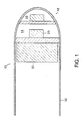
- an interventional device 10 includes an elongated member 12 and a display 14.
- the elongated member 12 can be inserted into a body for diagnostic and/or therapeutic procedures.
- the display 14 is located at the distal end of the elongated member 12.
- a sensing system 16 which is also located the distal end 18 of the elongated member 12, senses a bodily condition.
- the display 14 receives the sensed bodily condition from the sensing system 16 and displays a signal indicative of the sensed bodily condition.
- the display 14 includes an indicator 20 that provides a visible signal indicative of the bodily condition within a pre-existing field of view of the interventional device or of a remote display system.
- the indicator 20 can comprise at least one of the following: (a) light emitters (e.g., a light emitting diode. a liquid crystal display or a multi-color display); (b) an optical emitter, (b) a chemical indicator (e.g., litmus paper); or (c) a polymeric emitter (e.g., an organic light emitting diode).
- the indicator 20 can indicate states. such as ON or OFF, a numeral. letter, shape or image.
- the indicator 20 be a projection display that projects indicia upon the interventional device or on tissue.
- a projection display can include a light emitter focused by a lens and scanned with a 2-axis piezoelectric scanner. Other types of projection displays, which are known in the art, can be used.
- the interventional device can also include a power source 22 in the distal end of the interventional device.
- the power source 22 provides power to the display 14 and can be a small battery.
- the sensing system 16 can comprises a sensor or a light source in combination with a light detector.
- the detector is adapted for monitoring light emissions from the light source.
- the sensing system 16 can be a fluorescence detection system.
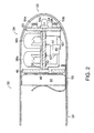
- an interventional device 30 includes an elongated member 32 insertible into a body (not shown) for diagnostic and/or therapeutic procedures.
- a display 34 is mounted onto a mounting structure 36 at the distal end of the elongated member 32.
- the display 34 includes a pair of light emitting diodes (LEDs) 38a, 38b for providing a visible signal indicative of the bodily condition within a pre-existing field of view.
- the LEDs 38a, 38b are electrically connected to a signal processor 40 via electrical lines 42.
- a power source 44 provides power to the display via an electrical contact 46, the signal processor 40 and electrical lines 41, 42.
- the power source 44 is located adjacent a mounting structure 48 and secured by a ground spring 30.
- the sensing system 52 is mounted to a mounting structure 53 at the distal end of the interventional device 30 and comprises an LED 54 and a pair of detectors 56a, 56b. Filters 58a, 58b can be disposed adjacent the detectors 56a, 56b.
- the LED 54 emits light that impinges upon tissue under examination.
- the detectors 56a, 56b in combination with the filters 58a, 58b selectively detecting spectral emissions (e.g., fluorescence emitted by the tissue with a pre-determined wavelength range.
- the detectors 56a, 56b are electrically connected to the processor 40 via the signal line 60.
- the processor 40 provides a signal indicative of a bodily condition to one of the LEDs 38a, 38b.
- One of the LEDs turns ON to provide an indication of the sensed bodily condition.
- the distal end of the intervention device is at least semi-transparent, thereby allowing the user to readily observe the activated LED.
- an interventional device 70 includes an electrode-based sensing system. Said device does not form part of the invention.
- the sensing system 72 includes a pair of electrodes 74a, 74b mounted at the distal end of the interventional device 70 for sensing a bodily condition.
- the electrodes 74a, 74b a bodily condition and provide corresponding signals to the processor 40 via signal lines 76.
- the processor 40 provides a signal indicative of a bodily condition to one of the LEDs 38a. 38b.
- One of the LEDs turns ON to display an indication of the sensed bodily condition.
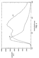
- FIG. 4 is a graph illustrating the fluorescence spectrum for normal and cancerous bladder tissue.
- An excitation wavelength of around 300 nanometers is used to excited suspicious bladder tissue.
- the resulting tissue fluorescence curves for normal tissue 80 and cancerous tissue 82 is shown.
- For normal tissue. a peak exists in the 440 to 460 nanometer range.
- For cancerous tissue. a peak exists in the 370 nanometer range. Both of these spectral responses are in the ultraviolet or blue range of the frequency spectrum and may not be readily visible to the human eye, which has limited sensitivity below 400 nanometers.
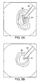
- FIGS. 5A and 5B are illustrations of the display located at the distal end of an interventional device for cancerous and normal colon tissue.
- an interventional device 90 is positioned adjacent tissue 92.
- the device 90 includes a display 94 having a first color and a second color. both of which can be visible to the human eye.
- the display can include a pair of LEDs.
- the sensing system (not shown) senses a bodily condition. In response to the sensed bodily condition, the display 94 generates the first color to indicate cancerous tissue.
- the interventional device 90 is positioned adjacent tissue 96.
- the sensing system (not shown) senses a bodily condition. In response to the sensed bodily condition, the display generates the second color to indicate normal tissue.
Description
Claims (10)
- An interventional device (10,30,70,90) comprising:an elongated member (12, 32) having a distal end insertable into a body;a sensing system (16,52,72) and a display (14,34,94) characterised in that the sensing system (16,52,72) is disposed in the distal end of the elongated member (12,32) for sensing a bodily condition; andthe display (14,34,94) located on the distal end (18) of the elongated member (12,32), the display (14,34,94) being coupled to the sensing system (16,52,72) for receiving the sensed bodily condition and providing a visible signal indicative of a bodily condition, wherein the sensing system (16,52,72) comprises at least one light source and at least one light detector.
- The interventional device (10,30,70,90) of claim 1, wherein the display (14,34,94) further comprises an indicator (20) which provides a visible signal indicative of a bodily condition.
- The interventional device (10,30,70,90) of claim 2, wherein the indicator (20) comprises:(a) at least one light emitter (38a,38b);(b) a light emitting diode;(c) a liquid crystal display, or(d) a projection display;(e) at least one optical emitter;(f) at least one chemical indicator;(g) at least one polymeric emitter; or(h) at least one organic light emitting diode.
- The interventional device (10,30,70,90) of claim 1, further comprising:a power source (22,44) for providing power to the display (14,34,94).
- The interventional device (10,30,70,90) of any of claims 1 to 4, wherein the display (14,34,94) receives the sensed bodily condition from the sensing system (16,52,72) and provides a visible signal indicative of the sensed bodily condition.
- The interventional device (10,30,70,90) of any of claims 1 to 5, wherein the sensing system (16,52,72) comprises at least one sensor.
- The interventional device (10,30,70,90) of claim 6 wherein at least one of the sensors comprises an electrode.
- The interventional device (10,30,70,90) of claim 1, wherein at least one of the detectors (56a,56b) is adapted for monitoring light emission from at least one of the light sources.
- The interventional device (10,30,70,90) of claim 8, further comprising at least one filter (58a,58b) disposed adjacent at least one of the detectors (56a,56b) for selectively detecting light emission having a predetermined wavelength.
- The interventional device (10,30,70,90) of any of claims 1 to 9, wherein the display (14,34,94) provides a visible signal indicative of the bodily condition within a pre-existing field of view otherwise provided by the interventional device (10,30,70,90).
Applications Claiming Priority (3)
| Application Number | Priority Date | Filing Date | Title |
|---|---|---|---|
| US939612 | 1997-09-29 | ||
| US08/939,612 US6185443B1 (en) | 1997-09-29 | 1997-09-29 | Visible display for an interventional device |
| PCT/US1998/020019 WO1999016345A1 (en) | 1997-09-29 | 1998-09-25 | Visible display for an interventional device |
Publications (2)
| Publication Number | Publication Date |
|---|---|
| EP1018932A1 EP1018932A1 (en) | 2000-07-19 |
| EP1018932B1 true EP1018932B1 (en) | 2004-07-14 |
Family
ID=25473458
Family Applications (1)
| Application Number | Title | Priority Date | Filing Date |
|---|---|---|---|
| EP98948517A Expired - Lifetime EP1018932B1 (en) | 1997-09-29 | 1998-09-25 | Visible display for an interventional device |
Country Status (6)
| Country | Link |
|---|---|
| US (2) | US6185443B1 (en) |
| EP (1) | EP1018932B1 (en) |
| JP (1) | JP2001517519A (en) |
| AU (1) | AU756125B2 (en) |
| DE (1) | DE69825067T2 (en) |
| WO (1) | WO1999016345A1 (en) |
Families Citing this family (67)
| Publication number | Priority date | Publication date | Assignee | Title |
|---|---|---|---|---|
| US6119031A (en) * | 1996-11-21 | 2000-09-12 | Boston Scientific Corporation | Miniature spectrometer |
| US6185443B1 (en) * | 1997-09-29 | 2001-02-06 | Boston Scientific Corporation | Visible display for an interventional device |
| US6238348B1 (en) * | 1997-07-22 | 2001-05-29 | Scimed Life Systems, Inc. | Miniature spectrometer system and method |
| US6324418B1 (en) * | 1997-09-29 | 2001-11-27 | Boston Scientific Corporation | Portable tissue spectroscopy apparatus and method |
| US6289229B1 (en) * | 1998-01-20 | 2001-09-11 | Scimed Life Systems, Inc. | Readable probe array for in vivo use |
| US7555333B2 (en) * | 2000-06-19 | 2009-06-30 | University Of Washington | Integrated optical scanning image acquisition and display |
| WO2003020103A2 (en) * | 2001-09-04 | 2003-03-13 | Amit Technology Science & Medicine Ltd. | Method of and device for therapeutic illumination of internal organs and tissues |
| US8423110B2 (en) * | 2002-01-09 | 2013-04-16 | Boston Scientific Scimed, Inc. | Imaging device and related methods |
| US9572095B2 (en) * | 2002-05-06 | 2017-02-14 | Avaya Inc. | Intelligent selection of message delivery mechanism |
| US9558475B2 (en) * | 2002-05-06 | 2017-01-31 | Avaya Inc. | Location based to-do list reminders |
| US7118529B2 (en) * | 2002-11-29 | 2006-10-10 | Given Imaging, Ltd. | Method and apparatus for transmitting non-image information via an image sensor in an in vivo imaging system |
| US8712549B2 (en) * | 2002-12-11 | 2014-04-29 | Proteus Digital Health, Inc. | Method and system for monitoring and treating hemodynamic parameters |
| US7419483B2 (en) * | 2003-02-07 | 2008-09-02 | Alfred E. Mann Institute For Biomedical Engineering At The University Of Southern California | Surgical drain with positioning and protective features |
| US20040199052A1 (en) | 2003-04-01 | 2004-10-07 | Scimed Life Systems, Inc. | Endoscopic imaging system |
| US7901348B2 (en) | 2003-12-12 | 2011-03-08 | University Of Washington | Catheterscope 3D guidance and interface system |
| US20050137459A1 (en) | 2003-12-17 | 2005-06-23 | Scimed Life Systems, Inc. | Medical device with OLED illumination light source |
| US20060015013A1 (en) * | 2004-06-30 | 2006-01-19 | Zvika Gilad | Device and method for in vivo illumination |
| US7530948B2 (en) * | 2005-02-28 | 2009-05-12 | University Of Washington | Tethered capsule endoscope for Barrett's Esophagus screening |
| US20070083100A1 (en) * | 2005-07-20 | 2007-04-12 | Sebastian Schulz-Stubner | Ventriculostomy Catheter with In Situ Ultrasound Capability |
| US9168383B2 (en) | 2005-10-14 | 2015-10-27 | Pacesetter, Inc. | Leadless cardiac pacemaker with conducted communication |
| EP2471452B1 (en) * | 2005-10-14 | 2014-12-10 | Pacesetter, Inc. | Cardiac pacing system and method of conveying information therein |
| WO2007067163A1 (en) * | 2005-11-23 | 2007-06-14 | University Of Washington | Scanning beam with variable sequential framing using interrupted scanning resonance |
| US8478386B2 (en) | 2006-01-10 | 2013-07-02 | Accuvein Inc. | Practitioner-mounted micro vein enhancer |
| US11278240B2 (en) | 2006-01-10 | 2022-03-22 | Accuvein, Inc. | Trigger-actuated laser vein contrast enhancer |
| US10813588B2 (en) | 2006-01-10 | 2020-10-27 | Accuvein, Inc. | Micro vein enhancer |
| US8489178B2 (en) | 2006-06-29 | 2013-07-16 | Accuvein Inc. | Enhanced laser vein contrast enhancer with projection of analyzed vein data |
| US9854977B2 (en) | 2006-01-10 | 2018-01-02 | Accuvein, Inc. | Scanned laser vein contrast enhancer using a single laser, and modulation circuitry |
| US11253198B2 (en) | 2006-01-10 | 2022-02-22 | Accuvein, Inc. | Stand-mounted scanned laser vein contrast enhancer |
| US8838210B2 (en) | 2006-06-29 | 2014-09-16 | AccuView, Inc. | Scanned laser vein contrast enhancer using a single laser |
| US9492117B2 (en) | 2006-01-10 | 2016-11-15 | Accuvein, Inc. | Practitioner-mounted micro vein enhancer |
| US8255040B2 (en) * | 2006-06-29 | 2012-08-28 | Accuvein, Llc | Micro vein enhancer |
| US8152718B2 (en) * | 2006-02-07 | 2012-04-10 | Boston Scientific Scimed, Inc. | Medical device light source |
| JP2009528128A (en) * | 2006-03-03 | 2009-08-06 | ユニヴァーシティ オブ ワシントン | Multi-clad optical fiber scanner |
| US8114121B2 (en) | 2006-06-22 | 2012-02-14 | Tyco Healthcare Group Lp | Tissue vitality comparator with light pipe with fiber optic imaging bundle |
| US10238294B2 (en) | 2006-06-29 | 2019-03-26 | Accuvein, Inc. | Scanned laser vein contrast enhancer using one laser |
| US8665507B2 (en) * | 2006-06-29 | 2014-03-04 | Accuvein, Inc. | Module mounting mirror endoscopy |
| US8730321B2 (en) | 2007-06-28 | 2014-05-20 | Accuvein, Inc. | Automatic alignment of a contrast enhancement system |
| US8594770B2 (en) | 2006-06-29 | 2013-11-26 | Accuvein, Inc. | Multispectral detection and presentation of an object's characteristics |
| US8463364B2 (en) * | 2009-07-22 | 2013-06-11 | Accuvein Inc. | Vein scanner |
| US20080058629A1 (en) * | 2006-08-21 | 2008-03-06 | University Of Washington | Optical fiber scope with both non-resonant illumination and resonant collection/imaging for multiple modes of operation |
| US20080132834A1 (en) * | 2006-12-04 | 2008-06-05 | University Of Washington | Flexible endoscope tip bending mechanism using optical fibers as tension members |
| US20080221388A1 (en) * | 2007-03-09 | 2008-09-11 | University Of Washington | Side viewing optical fiber endoscope |
| US7996068B2 (en) * | 2007-03-14 | 2011-08-09 | The Board Of Trustees Of The Leland Stanford Junior University | Surgical method and apparatus for identification of fluorescence |
| US8840566B2 (en) | 2007-04-02 | 2014-09-23 | University Of Washington | Catheter with imaging capability acts as guidewire for cannula tools |
| US20080243030A1 (en) * | 2007-04-02 | 2008-10-02 | University Of Washington | Multifunction cannula tools |
| WO2008137710A1 (en) * | 2007-05-03 | 2008-11-13 | University Of Washington | High resolution optical coherence tomography based imaging for intraluminal and interstitial use implemented with a reduced form factor |
| EP2203216A1 (en) * | 2007-09-20 | 2010-07-07 | Nanostim, Inc. | Leadless cardiac pacemaker with secondary fixation capability |
| US20090137893A1 (en) * | 2007-11-27 | 2009-05-28 | University Of Washington | Adding imaging capability to distal tips of medical tools, catheters, and conduits |
| US8515507B2 (en) * | 2008-06-16 | 2013-08-20 | Given Imaging Ltd. | Device and method for detecting in-vivo pathology |
| WO2010088687A1 (en) | 2009-02-02 | 2010-08-05 | Nanostim, Inc. | Leadless cardiac pacemaker with secondary fixation capability |
| US20100217115A1 (en) * | 2009-02-25 | 2010-08-26 | Hushek Stephen G | Temperature sensing within a patient during mr imaging |
| WO2010119916A1 (en) * | 2009-04-13 | 2010-10-21 | Olympus Corporation | Fluorescence sensor, needle-type fluorescence sensor, and method for measuring analyte |
| US9061109B2 (en) | 2009-07-22 | 2015-06-23 | Accuvein, Inc. | Vein scanner with user interface |
| US20110077708A1 (en) * | 2009-09-28 | 2011-03-31 | Alan Ostroff | MRI Compatible Leadless Cardiac Pacemaker |
| EP2515759A4 (en) | 2009-12-23 | 2015-01-21 | Given Imaging Inc | Method of evaluating constipation using an ingestible capsule |
| EP2627403A4 (en) | 2010-10-12 | 2014-03-26 | Nanostim Inc | Temperature sensor for a leadless cardiac pacemaker |
| US9060692B2 (en) | 2010-10-12 | 2015-06-23 | Pacesetter, Inc. | Temperature sensor for a leadless cardiac pacemaker |
| WO2012051235A1 (en) | 2010-10-13 | 2012-04-19 | Nanostim, Inc. | Leadless cardiac pacemaker with anti-unscrewing feature |
| EP2651502B1 (en) | 2010-12-13 | 2016-11-09 | Pacesetter, Inc. | Pacemaker retrieval systems |
| EP2651494B1 (en) | 2010-12-13 | 2017-02-15 | Pacesetter, Inc. | Delivery catheter |
| EP2654889B1 (en) | 2010-12-20 | 2017-03-01 | Pacesetter, Inc. | Leadless pacemaker with radial fixation mechanism |
| WO2013067496A2 (en) | 2011-11-04 | 2013-05-10 | Nanostim, Inc. | Leadless cardiac pacemaker with integral battery and redundant welds |
| EP2879758B1 (en) | 2012-08-01 | 2018-04-18 | Pacesetter, Inc. | Biostimulator circuit with flying cell |
| US9072426B2 (en) | 2012-08-02 | 2015-07-07 | AccuVein, Inc | Device for detecting and illuminating vasculature using an FPGA |
| US10517483B2 (en) | 2012-12-05 | 2019-12-31 | Accuvein, Inc. | System for detecting fluorescence and projecting a representative image |
| US20150015254A1 (en) | 2013-05-17 | 2015-01-15 | Imris Inc. | Control of SAR Values in MR Imaging |
| CN106361257A (en) * | 2016-08-31 | 2017-02-01 | 马东阁 | OLED (optical light emitting diode) oral cavity detection equipment |
Family Cites Families (152)
| Publication number | Priority date | Publication date | Assignee | Title |
|---|---|---|---|---|
| US2583937A (en) | 1952-01-29 | Surgical exploring and operating | ||
| US2002559A (en) | 1932-04-13 | 1935-05-28 | Wappler Frederick Charles | Means for surgical resection |
| DE888727C (en) | 1941-04-22 | 1953-09-03 | Quarzlampen Gmbh | Body cavity irradiation lamp |
| US3176114A (en) | 1962-07-16 | 1965-03-30 | Richard F Kneisley | Device for removing nasal hair |
| GB1485908A (en) | 1974-05-21 | 1977-09-14 | Nath G | Apparatus for applying light radiation |
| US4215275A (en) * | 1977-12-07 | 1980-07-29 | Luxtron Corporation | Optical temperature measurement technique utilizing phosphors |
| USRE31289E (en) | 1978-10-16 | 1983-06-28 | Welch Allyn, Inc. | Color endoscope with charge coupled device and television viewing |
| US4265121A (en) | 1978-11-13 | 1981-05-05 | Litton Industrial Products, Inc. | High resolution ultrasound diagnostic apparatus |
| US4274706A (en) | 1979-08-30 | 1981-06-23 | Hughes Aircraft Company | Wavelength multiplexer/demultiplexer for optical circuits |
| US4289966A (en) | 1980-04-10 | 1981-09-15 | The United States Of America As Represented By The Secretary Of The Army | Radiation energy detector and analyzer |
| DE3023130A1 (en) | 1980-06-20 | 1982-01-21 | Hasso von 4000 Düsseldorf Blücher | Mouth and nose steriliser - uses high intensity light flash of millisecond duration |
| US4340307A (en) | 1980-07-07 | 1982-07-20 | Beckman Instruments, Inc. | Bichromatic spectrophotometer with wavelength reversal |
| US4578061A (en) | 1980-10-28 | 1986-03-25 | Lemelson Jerome H | Injection catheter and method |
| US4803992A (en) | 1980-10-28 | 1989-02-14 | Lemelson Jerome H | Electro-optical instruments and methods for producing same |
| JPS57175345A (en) | 1981-04-22 | 1982-10-28 | Sumitomo Electric Industries | Sensor for live body organ spectrum analyser |
| US4472728A (en) | 1982-02-19 | 1984-09-18 | The United States Of America As Represented By The Administrator Of The National Aeronautics And Space Administration | Imaging X-ray spectrometer |
| JPS5940830A (en) | 1982-08-31 | 1984-03-06 | 浜松ホトニクス株式会社 | Apparatus for diagnosis of cancer using laser beam pulse |
| US4541272A (en) | 1983-05-13 | 1985-09-17 | Roland Bause | Electronically controlled fuel injection system |
| JPS6077731A (en) | 1983-10-03 | 1985-05-02 | オリンパス光学工業株式会社 | Endoscope apparatus using solid-image pick-up element |
| US4570638A (en) | 1983-10-14 | 1986-02-18 | Somanetics Corporation | Method and apparatus for spectral transmissibility examination and analysis |
| JPH0658457B2 (en) * | 1984-04-13 | 1994-08-03 | オリンパス光学工業株式会社 | Endoscope device |
| US4672972A (en) | 1984-08-13 | 1987-06-16 | Berke Howard R | Solid state NMR probe |
| JPS6188216A (en) * | 1984-10-08 | 1986-05-06 | Olympus Optical Co Ltd | Lighting device of endoscope |
| US5106387A (en) | 1985-03-22 | 1992-04-21 | Massachusetts Institute Of Technology | Method for spectroscopic diagnosis of tissue |
| US5199431A (en) | 1985-03-22 | 1993-04-06 | Massachusetts Institute Of Technology | Optical needle for spectroscopic diagnosis |
| US5318024A (en) | 1985-03-22 | 1994-06-07 | Massachusetts Institute Of Technology | Laser endoscope for spectroscopic imaging |
| US4718417A (en) | 1985-03-22 | 1988-01-12 | Massachusetts Institute Of Technology | Visible fluorescence spectral diagnostic for laser angiosurgery |
| US5125404A (en) | 1985-03-22 | 1992-06-30 | Massachusetts Institute Of Technology | Apparatus and method for obtaining spectrally resolved spatial images of tissue |
| US5034010A (en) | 1985-03-22 | 1991-07-23 | Massachusetts Institute Of Technology | Optical shield for a laser catheter |
| JPH0658458B2 (en) | 1985-07-12 | 1994-08-03 | オリンパス光学工業株式会社 | Endoscope device |
| US5042494A (en) | 1985-11-13 | 1991-08-27 | Alfano Robert R | Method and apparatus for detecting cancerous tissue using luminescence excitation spectra |
| US4930516B1 (en) | 1985-11-13 | 1998-08-04 | Laser Diagnostic Instr Inc | Method for detecting cancerous tissue using visible native luminescence |
| US4895156A (en) * | 1986-07-02 | 1990-01-23 | Schulze John E | Sensor system using fluorometric decay measurements |
| US4813790A (en) * | 1986-07-28 | 1989-03-21 | Becton, Dickinson And Company | Mouth grips for oral thermometers |
| US4872458A (en) | 1986-09-16 | 1989-10-10 | Olympus Optical Co., Ltd. | Thermotherapy apparatus |
| JPH07108284B2 (en) * | 1986-12-26 | 1995-11-22 | オリンパス光学工業株式会社 | Extracorporeal observation device |
| JPS62249636A (en) * | 1987-04-15 | 1987-10-30 | オリンパス光学工業株式会社 | Endoscope |
| JPS63260526A (en) * | 1987-04-17 | 1988-10-27 | オリンパス光学工業株式会社 | Endoscopic apparatus |
| US4902896A (en) | 1987-05-08 | 1990-02-20 | Mine Safety Appliances Company | Infrared fluid analyzer |
| US4784158A (en) | 1987-08-21 | 1988-11-15 | Okimoto Paul M | Vaginal testing applicator and method |
| US4894547A (en) | 1987-09-28 | 1990-01-16 | Yale University | Optical method and apparatus for detecting and measuring aging, photoaging, dermal disease and pigmentation in skin |
| US5001556A (en) | 1987-09-30 | 1991-03-19 | Olympus Optical Co., Ltd. | Endoscope apparatus for processing a picture image of an object based on a selected wavelength range |
| AU604567B2 (en) | 1987-10-08 | 1990-12-20 | Pacesetter Ab | Implantable blood oxygen sensor and method of use |
| US4938602A (en) | 1987-10-15 | 1990-07-03 | Electronic Instrumentation And Technology, Inc. | Automated process monitoring |
| US4854302A (en) | 1987-11-12 | 1989-08-08 | Welch Allyn, Inc. | Video equipped endoscope with needle probe |
| US5021888A (en) | 1987-12-18 | 1991-06-04 | Kabushiki Kaisha Toshiba | Miniaturized solid state imaging device |
| US4928172A (en) | 1988-01-07 | 1990-05-22 | Olympus Optical Co., Ltd. | Endoscope output signal control device and endoscope apparatus making use of the same |
| US5051823A (en) | 1988-01-28 | 1991-09-24 | Fuji Optical Systems, Inc. | Dental instrument including laser device and electronic video dental camera |
| USRE34110E (en) | 1988-04-22 | 1992-10-27 | Opielab, Inc. | Endoscope for use with a disposable sheath |
| US5242437A (en) | 1988-06-10 | 1993-09-07 | Trimedyne Laser Systems, Inc. | Medical device applying localized high intensity light and heat, particularly for destruction of the endometrium |
| US4981138A (en) | 1988-06-30 | 1991-01-01 | Yale University | Endoscopic fiberoptic fluorescence spectrometer |
| US4882623A (en) | 1988-08-11 | 1989-11-21 | Olympus Optical Co., Ltd. | Signal processing apparatus for endoscope capable of changing outline enhancement frequency |
| US5036853A (en) | 1988-08-26 | 1991-08-06 | Polartechnics Ltd. | Physiological probe |
| US4923263A (en) | 1988-09-22 | 1990-05-08 | The United States Of America As Represented By The Secretary Of The Army | Rotating mirror optical scanning device |
| US5402778A (en) | 1993-01-19 | 1995-04-04 | Nim Incorporated | Spectrophotometric examination of tissue of small dimension |
| US5187672A (en) | 1989-02-06 | 1993-02-16 | Nim Incorporated | Phase modulation spectroscopic system |
| US5555885A (en) | 1988-12-21 | 1996-09-17 | Non-Invasive Technology, Inc. | Examination of breast tissue using time-resolved spectroscopy |
| US5553614A (en) | 1988-12-21 | 1996-09-10 | Non-Invasive Technology, Inc. | Examination of biological tissue using frequency domain spectroscopy |
| ATE133545T1 (en) | 1988-12-21 | 1996-02-15 | Massachusetts Inst Technology | METHOD FOR LASER-INDUCED FLUORESCENCE OF TISSUE |
| US5386827A (en) | 1993-03-30 | 1995-02-07 | Nim Incorporated | Quantitative and qualitative in vivo tissue examination using time resolved spectroscopy |
| JPH02189129A (en) * | 1989-01-17 | 1990-07-25 | Furuno Electric Co Ltd | Bioimpedance measuring device |
| SE8900612D0 (en) | 1989-02-22 | 1989-02-22 | Jonas Johansson | TISSUE CHARACTERIZATION USING A BLOOD-FREE FLUORESCENCE CRITERIA |
| US5421337A (en) | 1989-04-14 | 1995-06-06 | Massachusetts Institute Of Technology | Spectral diagnosis of diseased tissue |
| US5201318A (en) | 1989-04-24 | 1993-04-13 | Rava Richard P | Contour mapping of spectral diagnostics |
| JPH0221839A (en) * | 1989-05-02 | 1990-01-24 | Olympus Optical Co Ltd | Endoscope |
| US5009655A (en) | 1989-05-24 | 1991-04-23 | C. R. Bard, Inc. | Hot tip device with optical diagnostic capability |
| US4934340A (en) | 1989-06-08 | 1990-06-19 | Hemo Laser Corporation | Device for guiding medical catheters and scopes |
| JPH0357425A (en) | 1989-07-26 | 1991-03-12 | Kowa Co | Eyeground inspection device |
| US5024226A (en) | 1989-08-17 | 1991-06-18 | Critikon, Inc. | Epidural oxygen sensor |
| US5045056A (en) | 1989-09-15 | 1991-09-03 | Behl Robert S | Method and device for thermal ablation of hollow body organs |
| JP2852774B2 (en) | 1989-11-22 | 1999-02-03 | 株式会社エス・エル・ティ・ジャパン | Diagnostic device for living tissue and treatment device provided with the diagnostic device |
| US5172693A (en) | 1990-01-16 | 1992-12-22 | Doody Michael C | Prenatal non-invasive detection of meconium stained amniotic fluid |
| US5131398A (en) | 1990-01-22 | 1992-07-21 | Mediscience Technology Corp. | Method and apparatus for distinguishing cancerous tissue from benign tumor tissue, benign tissue or normal tissue using native fluorescence |
| DE4005743A1 (en) | 1990-02-23 | 1991-08-29 | Wolf Gmbh Richard | Lithotriptor to destroy gallstones intra-or trans-luminally - has shock-wave generator, lead contg. incompressible material, and opt balloon to press generator against gall bladder |
| JP2834521B2 (en) | 1990-03-15 | 1998-12-09 | 株式会社日立製作所 | LED array diagnostic device |
| US5166755A (en) | 1990-05-23 | 1992-11-24 | Nahum Gat | Spectrometer apparatus |
| US5062428A (en) | 1990-06-04 | 1991-11-05 | Nim Incorporated | Method and device for in vivo diagnosis detecting IR emission by body organ |
| US5116759A (en) | 1990-06-27 | 1992-05-26 | Fiberchem Inc. | Reservoir chemical sensors |
| US5197470A (en) | 1990-07-16 | 1993-03-30 | Eastman Kodak Company | Near infrared diagnostic method and instrument |
| US5053033A (en) | 1990-10-10 | 1991-10-01 | Boston Advanced Technologies, Inc. | Inhibition of restenosis by ultraviolet radiation |
| JP3164609B2 (en) | 1990-10-31 | 2001-05-08 | オリンパス光学工業株式会社 | Endoscope device |
| US5193542A (en) | 1991-01-28 | 1993-03-16 | Missanelli John S | Peripartum oximetric monitoring apparatus |
| EP0501034A1 (en) | 1991-01-30 | 1992-09-02 | CeramOptec GmbH | Illuminated leading probe device |
| US5261410A (en) | 1991-02-07 | 1993-11-16 | Alfano Robert R | Method for determining if a tissue is a malignant tumor tissue, a benign tumor tissue, or a normal or benign tissue using Raman spectroscopy |
| JPH05506176A (en) * | 1991-02-13 | 1993-09-16 | アプライド メディカル リソーセス インコーポレイテッド | surgical trocar |
| US5280788A (en) | 1991-02-26 | 1994-01-25 | Massachusetts Institute Of Technology | Devices and methods for optical diagnosis of tissue |
| US5377676A (en) | 1991-04-03 | 1995-01-03 | Cedars-Sinai Medical Center | Method for determining the biodistribution of substances using fluorescence spectroscopy |
| US5313306A (en) | 1991-05-13 | 1994-05-17 | Telerobotics International, Inc. | Omniview motionless camera endoscopy system |
| US5542928A (en) | 1991-05-17 | 1996-08-06 | Innerdyne, Inc. | Method and device for thermal ablation having improved heat transfer |
| US5417210A (en) * | 1992-05-27 | 1995-05-23 | International Business Machines Corporation | System and method for augmentation of endoscopic surgery |
| US5279309A (en) * | 1991-06-13 | 1994-01-18 | International Business Machines Corporation | Signaling device and method for monitoring positions in a surgical operation |
| US5233621A (en) | 1991-06-27 | 1993-08-03 | Intellectual Property Development Associates Of Connecticut, Inc. | Second harmonic generation and self frequency doubling laser materials comprised of bulk germanosilicate and aluminosilicate glasses |
| US5262645A (en) | 1991-09-03 | 1993-11-16 | General Motors Corporation | Sensor for measuring alcohol content of alcohol gasoline fuel mixtures |
| DE4129438A1 (en) | 1991-09-04 | 1993-03-18 | Siemens Ag | MEASURING ARRANGEMENT FOR THE EXAMINATION OF AN OBJECT WITH VISIBLE, NIR OR IR LIGHT |
| JPH05128574A (en) | 1991-10-31 | 1993-05-25 | Olympus Optical Co Ltd | Optical head |
| US5467767A (en) | 1991-11-25 | 1995-11-21 | Alfano; Robert R. | Method for determining if tissue is malignant as opposed to non-malignant using time-resolved fluorescence spectroscopy |
| US5348018A (en) | 1991-11-25 | 1994-09-20 | Alfano Robert R | Method for determining if tissue is malignant as opposed to non-malignant using time-resolved fluorescence spectroscopy |
| US5213569A (en) | 1992-03-31 | 1993-05-25 | Davis Peter L | Tip for a tissue phacoemulsification device |
| US5512757A (en) | 1992-04-06 | 1996-04-30 | Rosemount Analytical, Inc. | Spectrophotometer and optical system therefor |
| US5305748A (en) | 1992-06-05 | 1994-04-26 | Wilk Peter J | Medical diagnostic system and related method |
| US5452723A (en) | 1992-07-24 | 1995-09-26 | Massachusetts Institute Of Technology | Calibrated spectrographic imaging |
| US5772597A (en) | 1992-09-14 | 1998-06-30 | Sextant Medical Corporation | Surgical tool end effector |
| US5206174A (en) | 1992-09-24 | 1993-04-27 | Eg&G Idaho, Inc. | Method of photon spectral analysis |
| US5351532A (en) | 1992-10-08 | 1994-10-04 | Paradigm Technologies | Methods and apparatus for making chemical concentration measurements in a sub-surface exploration probe |
| US5467104A (en) | 1992-10-22 | 1995-11-14 | Board Of Regents Of The University Of Washington | Virtual retinal display |
| US5383467A (en) | 1992-11-18 | 1995-01-24 | Spectrascience, Inc. | Guidewire catheter and apparatus for diagnostic imaging |
| US5350375A (en) | 1993-03-15 | 1994-09-27 | Yale University | Methods for laser induced fluorescence intensity feedback control during laser angioplasty |
| JPH06269391A (en) * | 1993-03-19 | 1994-09-27 | Olympus Optical Co Ltd | Body cavity diagnosing treatment apparatus |
| JPH06285106A (en) | 1993-03-30 | 1994-10-11 | Shimadzu Corp | Ultrasonic therapeutic device |
| US5413108A (en) | 1993-04-21 | 1995-05-09 | The Research Foundation Of City College Of New York | Method and apparatus for mapping a tissue sample for and distinguishing different regions thereof based on luminescence measurements of cancer-indicative native fluorophor |
| US5421339A (en) | 1993-05-12 | 1995-06-06 | Board Of Regents, The University Of Texas System | Diagnosis of dysplasia using laser induced fluoroescence |
| CA2166201A1 (en) * | 1993-06-30 | 1995-01-12 | Barry Colin Crane | Biphasic material |
| US5445608A (en) | 1993-08-16 | 1995-08-29 | James C. Chen | Method and apparatus for providing light-activated therapy |
| US5456252A (en) | 1993-09-30 | 1995-10-10 | Cedars-Sinai Medical Center | Induced fluorescence spectroscopy blood perfusion and pH monitor and method |
| ZA948393B (en) | 1993-11-01 | 1995-06-26 | Polartechnics Ltd | Method and apparatus for tissue type recognition |
| JP3182601B2 (en) * | 1993-11-01 | 2001-07-03 | ポーラテクニクス・リミテッド | Tissue type recognition method and apparatus therefor |
| JPH07155291A (en) * | 1993-12-03 | 1995-06-20 | Olympus Optical Co Ltd | Fluorescence observation apparatus |
| US5417207A (en) | 1993-12-06 | 1995-05-23 | Sensor Devices, Inc. | Apparatus for the invasive use of oximeter probes |
| US5417688A (en) * | 1993-12-22 | 1995-05-23 | Elstrom; John A. | Optical distal targeting system for an intramedullary nail |
| US5405369A (en) | 1994-01-25 | 1995-04-11 | Medical College Of Ohio | Photochemical ablation of gastro-intestinal tissue for augmentation of an organ |
| US5398844A (en) | 1994-01-31 | 1995-03-21 | Boston Scientific Corporation | Multiple ligating band dispenser |
| US5408998A (en) * | 1994-03-10 | 1995-04-25 | Ethicon Endo-Surgery | Video based tissue oximetry |
| US5434940A (en) | 1994-03-24 | 1995-07-18 | The Whitaker Corporation | Active fiber needle |
| US5590660A (en) | 1994-03-28 | 1997-01-07 | Xillix Technologies Corp. | Apparatus and method for imaging diseased tissue using integrated autofluorescence |
| JP3490760B2 (en) | 1994-04-04 | 2004-01-26 | 昭 藤嶋 | Tumor treatment device |
| JPH07275200A (en) * | 1994-04-15 | 1995-10-24 | Asahi Optical Co Ltd | Illuminator for endoscope |
| US5429616A (en) | 1994-05-31 | 1995-07-04 | Schaffer; David I. | Occludable catheter |
| US5461229A (en) | 1994-06-06 | 1995-10-24 | Unisys Corporation | On-the-go optical spectroscopy soil analyzer |
| US5517997A (en) * | 1994-09-15 | 1996-05-21 | Gabriel Medical, Inc. | Transillumination of body members for protection during body invasive procedures |
| JP3467131B2 (en) * | 1994-09-21 | 2003-11-17 | ペンタックス株式会社 | Electronic endoscope device for fluorescence diagnosis |
| US5626139A (en) * | 1994-09-23 | 1997-05-06 | Artech Industries, Inc. | Tympanic thermometer |
| US5579773A (en) | 1994-09-30 | 1996-12-03 | Martin Marietta Energy Systems, Inc. | Laser-induced differential normalized fluorescence method for cancer diagnosis |
| US5545897A (en) | 1994-10-04 | 1996-08-13 | Santa Barbara Research Center | Optically-based chemical detection system |
| US5517313A (en) | 1995-02-21 | 1996-05-14 | Colvin, Jr.; Arthur E. | Fluorescent optical sensor |
| US5556421A (en) | 1995-02-22 | 1996-09-17 | Intermedics, Inc. | Implantable medical device with enclosed physiological parameter sensors or telemetry link |
| JP3560671B2 (en) * | 1995-02-23 | 2004-09-02 | オリンパス株式会社 | Fluorescence observation device |
| DE19506484C2 (en) | 1995-02-24 | 1999-09-16 | Stiftung Fuer Lasertechnologie | Method and device for selective non-invasive laser myography (LMG) |
| US5690117A (en) * | 1995-03-20 | 1997-11-25 | Gilbert; John W. | Ultrasonic-fiberoptic imaging ventricular catheter |
| US5571152A (en) | 1995-05-26 | 1996-11-05 | Light Sciences Limited Partnership | Microminiature illuminator for administering photodynamic therapy |
| US5775331A (en) * | 1995-06-07 | 1998-07-07 | Uromed Corporation | Apparatus and method for locating a nerve |
| DE19544501A1 (en) | 1995-11-29 | 1997-06-05 | Boehringer Mannheim Gmbh | Device for light reflection measurements |
| JP3525235B2 (en) * | 1995-12-06 | 2004-05-10 | 松下電器産業株式会社 | Optical diagnostic equipment |
| US5647368A (en) | 1996-02-28 | 1997-07-15 | Xillix Technologies Corp. | Imaging system for detecting diseased tissue using native fluorsecence in the gastrointestinal and respiratory tract |
| US5800478A (en) * | 1996-03-07 | 1998-09-01 | Light Sciences Limited Partnership | Flexible microcircuits for internal light therapy |
| US5928137A (en) * | 1996-05-03 | 1999-07-27 | Green; Philip S. | System and method for endoscopic imaging and endosurgery |
| US5730134A (en) * | 1996-09-09 | 1998-03-24 | General Electric Company | System to monitor temperature near an invasive device during magnetic resonance procedures |
| US5829878A (en) * | 1996-10-15 | 1998-11-03 | Micro Idea Instruments, Ltd. | Digital fever thermometer having an illuminated display |
| US5885293A (en) * | 1997-03-03 | 1999-03-23 | Innovasive Devices, Inc. | Apparatus and method for cutting a surface at a repeatable angle |
| US6238348B1 (en) * | 1997-07-22 | 2001-05-29 | Scimed Life Systems, Inc. | Miniature spectrometer system and method |
| US6185443B1 (en) * | 1997-09-29 | 2001-02-06 | Boston Scientific Corporation | Visible display for an interventional device |
| US6324418B1 (en) * | 1997-09-29 | 2001-11-27 | Boston Scientific Corporation | Portable tissue spectroscopy apparatus and method |
| US6510336B1 (en) * | 2000-03-03 | 2003-01-21 | Intra Medical Imaging, Llc | Methods and devices to expand applications of intraoperative radiation probes |
-
1997
- 1997-09-29 US US08/939,612 patent/US6185443B1/en not_active Expired - Lifetime
-
1998
- 1998-09-25 EP EP98948517A patent/EP1018932B1/en not_active Expired - Lifetime
- 1998-09-25 DE DE69825067T patent/DE69825067T2/en not_active Expired - Lifetime
- 1998-09-25 JP JP2000513492A patent/JP2001517519A/en active Pending
- 1998-09-25 AU AU95071/98A patent/AU756125B2/en not_active Ceased
- 1998-09-25 WO PCT/US1998/020019 patent/WO1999016345A1/en active IP Right Grant
-
2000
- 2000-10-18 US US09/691,550 patent/US6882875B1/en not_active Expired - Fee Related
Also Published As
| Publication number | Publication date |
|---|---|
| JP2001517519A (en) | 2001-10-09 |
| EP1018932A1 (en) | 2000-07-19 |
| WO1999016345A1 (en) | 1999-04-08 |
| AU756125B2 (en) | 2003-01-02 |
| US6882875B1 (en) | 2005-04-19 |
| DE69825067T2 (en) | 2005-07-21 |
| AU9507198A (en) | 1999-04-23 |
| DE69825067D1 (en) | 2004-08-19 |
| US6185443B1 (en) | 2001-02-06 |
Similar Documents
| Publication | Publication Date | Title |
|---|---|---|
| EP1018932B1 (en) | Visible display for an interventional device | |
| US6324418B1 (en) | Portable tissue spectroscopy apparatus and method | |
| AU2003218069B2 (en) | Combination otoscope | |
| US9877644B2 (en) | Optical speculum | |
| US20050159646A1 (en) | Optical probe accessory device for use in in vivo diagnostic procedures | |
| JP2862099B2 (en) | Early cancer diagnostic device | |
| US20090012368A1 (en) | Imaging endoscope | |
| US20090118580A1 (en) | Image-type intubation-aiding device | |
| US7476197B2 (en) | Scanned beam imagers and endoscopes utilizing multiple light collectors | |
| EP3046496B1 (en) | Optical speculum | |
| EP2012651A2 (en) | Imaging assembly with transparent distal cap | |
| US9271640B2 (en) | Optical speculum | |
| US20030100819A1 (en) | Hand-held chemical sensing instrument | |
| JP2005319212A (en) | Fluorescence endoscope apparatus | |
| JPH0484948A (en) | Punctual ultrasonic probe | |
| EP1182963B1 (en) | Optical biopsy system | |
| JP4185313B2 (en) | Fluorescence measuring device | |
| JP2600218Y2 (en) | Cover type endoscope device | |
| JP4406133B2 (en) | Endoscope position detection device for endoscope | |
| JP2007044074A (en) | Ultrasonic diagnostic device | |
| JP6116381B2 (en) | Endoscope system | |
| JPS6314617B2 (en) | ||
| JP2796859B2 (en) | Ultrasound endoscope | |
| CN112336385A (en) | Endoscopic fluorescence imaging puncture system | |
| JP2009201797A (en) | Ultrasonic endoscope |
Legal Events
| Date | Code | Title | Description |
|---|---|---|---|
| PUAI | Public reference made under article 153(3) epc to a published international application that has entered the european phase |
Free format text: ORIGINAL CODE: 0009012 |
|
| 17P | Request for examination filed |
Effective date: 20000426 |
|
| AK | Designated contracting states |
Kind code of ref document: A1 Designated state(s): DE FR GB IE |
|
| 17Q | First examination report despatched |
Effective date: 20021022 |
|
| RAP1 | Party data changed (applicant data changed or rights of an application transferred) |
Owner name: BOSTON SCIENTIFIC LIMITED |
|
| GRAP | Despatch of communication of intention to grant a patent |
Free format text: ORIGINAL CODE: EPIDOSNIGR1 |
|
| GRAS | Grant fee paid |
Free format text: ORIGINAL CODE: EPIDOSNIGR3 |
|
| GRAA | (expected) grant |
Free format text: ORIGINAL CODE: 0009210 |
|
| AK | Designated contracting states |
Kind code of ref document: B1 Designated state(s): DE FR GB IE |
|
| REG | Reference to a national code |
Ref country code: GB Ref legal event code: FG4D |
|
| REF | Corresponds to: |
Ref document number: 69825067 Country of ref document: DE Date of ref document: 20040819 Kind code of ref document: P |
|
| REG | Reference to a national code |
Ref country code: IE Ref legal event code: FG4D |
|
| ET | Fr: translation filed | ||
| PLBE | No opposition filed within time limit |
Free format text: ORIGINAL CODE: 0009261 |
|
| STAA | Information on the status of an ep patent application or granted ep patent |
Free format text: STATUS: NO OPPOSITION FILED WITHIN TIME LIMIT |
|
| 26N | No opposition filed |
Effective date: 20050415 |
|
| PGFP | Annual fee paid to national office [announced via postgrant information from national office to epo] |
Ref country code: FR Payment date: 20070904 Year of fee payment: 10 |
|
| REG | Reference to a national code |
Ref country code: FR Ref legal event code: ST Effective date: 20090529 |
|
| PG25 | Lapsed in a contracting state [announced via postgrant information from national office to epo] |
Ref country code: FR Free format text: LAPSE BECAUSE OF NON-PAYMENT OF DUE FEES Effective date: 20080930 |
|
| PGFP | Annual fee paid to national office [announced via postgrant information from national office to epo] |
Ref country code: IE Payment date: 20090724 Year of fee payment: 12 |
|
| PGFP | Annual fee paid to national office [announced via postgrant information from national office to epo] |
Ref country code: GB Payment date: 20090807 Year of fee payment: 12 |
|
| PGFP | Annual fee paid to national office [announced via postgrant information from national office to epo] |
Ref country code: DE Payment date: 20090930 Year of fee payment: 12 |
|
| GBPC | Gb: european patent ceased through non-payment of renewal fee |
Effective date: 20100925 |
|
| REG | Reference to a national code |
Ref country code: IE Ref legal event code: MM4A |
|
| REG | Reference to a national code |
Ref country code: DE Ref legal event code: R119 Ref document number: 69825067 Country of ref document: DE Effective date: 20110401 |
|
| PG25 | Lapsed in a contracting state [announced via postgrant information from national office to epo] |
Ref country code: DE Free format text: LAPSE BECAUSE OF NON-PAYMENT OF DUE FEES Effective date: 20110401 Ref country code: IE Free format text: LAPSE BECAUSE OF NON-PAYMENT OF DUE FEES Effective date: 20100927 |
|
| PG25 | Lapsed in a contracting state [announced via postgrant information from national office to epo] |
Ref country code: GB Free format text: LAPSE BECAUSE OF NON-PAYMENT OF DUE FEES Effective date: 20100925 |