EP1018986B1 - Radially expandable nickel-titanium surgical stent - Google Patents
Radially expandable nickel-titanium surgical stent Download PDFInfo
- Publication number
- EP1018986B1 EP1018986B1 EP98949641A EP98949641A EP1018986B1 EP 1018986 B1 EP1018986 B1 EP 1018986B1 EP 98949641 A EP98949641 A EP 98949641A EP 98949641 A EP98949641 A EP 98949641A EP 1018986 B1 EP1018986 B1 EP 1018986B1
- Authority
- EP
- European Patent Office
- Prior art keywords
- stent
- adjacent
- segments
- circumferential
- radially
- Prior art date
- Legal status (The legal status is an assumption and is not a legal conclusion. Google has not performed a legal analysis and makes no representation as to the accuracy of the status listed.)
- Expired - Lifetime
Links
Images
Classifications
-
- C—CHEMISTRY; METALLURGY
- C22—METALLURGY; FERROUS OR NON-FERROUS ALLOYS; TREATMENT OF ALLOYS OR NON-FERROUS METALS
- C22F—CHANGING THE PHYSICAL STRUCTURE OF NON-FERROUS METALS AND NON-FERROUS ALLOYS
- C22F1/00—Changing the physical structure of non-ferrous metals or alloys by heat treatment or by hot or cold working
- C22F1/006—Resulting in heat recoverable alloys with a memory effect
-
- A—HUMAN NECESSITIES
- A61—MEDICAL OR VETERINARY SCIENCE; HYGIENE
- A61F—FILTERS IMPLANTABLE INTO BLOOD VESSELS; PROSTHESES; DEVICES PROVIDING PATENCY TO, OR PREVENTING COLLAPSING OF, TUBULAR STRUCTURES OF THE BODY, e.g. STENTS; ORTHOPAEDIC, NURSING OR CONTRACEPTIVE DEVICES; FOMENTATION; TREATMENT OR PROTECTION OF EYES OR EARS; BANDAGES, DRESSINGS OR ABSORBENT PADS; FIRST-AID KITS
- A61F2/00—Filters implantable into blood vessels; Prostheses, i.e. artificial substitutes or replacements for parts of the body; Appliances for connecting them with the body; Devices providing patency to, or preventing collapsing of, tubular structures of the body, e.g. stents
- A61F2/82—Devices providing patency to, or preventing collapsing of, tubular structures of the body, e.g. stents
- A61F2/86—Stents in a form characterised by the wire-like elements; Stents in the form characterised by a net-like or mesh-like structure
- A61F2/90—Stents in a form characterised by the wire-like elements; Stents in the form characterised by a net-like or mesh-like structure characterised by a net-like or mesh-like structure
- A61F2/91—Stents in a form characterised by the wire-like elements; Stents in the form characterised by a net-like or mesh-like structure characterised by a net-like or mesh-like structure made from perforated sheet material or tubes, e.g. perforated by laser cuts or etched holes
- A61F2/915—Stents in a form characterised by the wire-like elements; Stents in the form characterised by a net-like or mesh-like structure characterised by a net-like or mesh-like structure made from perforated sheet material or tubes, e.g. perforated by laser cuts or etched holes with bands having a meander structure, adjacent bands being connected to each other
- A61F2002/91525—Stents in a form characterised by the wire-like elements; Stents in the form characterised by a net-like or mesh-like structure characterised by a net-like or mesh-like structure made from perforated sheet material or tubes, e.g. perforated by laser cuts or etched holes with bands having a meander structure, adjacent bands being connected to each other within the whole structure different bands showing different meander characteristics, e.g. frequency or amplitude
-
- A—HUMAN NECESSITIES
- A61—MEDICAL OR VETERINARY SCIENCE; HYGIENE
- A61F—FILTERS IMPLANTABLE INTO BLOOD VESSELS; PROSTHESES; DEVICES PROVIDING PATENCY TO, OR PREVENTING COLLAPSING OF, TUBULAR STRUCTURES OF THE BODY, e.g. STENTS; ORTHOPAEDIC, NURSING OR CONTRACEPTIVE DEVICES; FOMENTATION; TREATMENT OR PROTECTION OF EYES OR EARS; BANDAGES, DRESSINGS OR ABSORBENT PADS; FIRST-AID KITS
- A61F2/00—Filters implantable into blood vessels; Prostheses, i.e. artificial substitutes or replacements for parts of the body; Appliances for connecting them with the body; Devices providing patency to, or preventing collapsing of, tubular structures of the body, e.g. stents
- A61F2/82—Devices providing patency to, or preventing collapsing of, tubular structures of the body, e.g. stents
- A61F2/86—Stents in a form characterised by the wire-like elements; Stents in the form characterised by a net-like or mesh-like structure
- A61F2/90—Stents in a form characterised by the wire-like elements; Stents in the form characterised by a net-like or mesh-like structure characterised by a net-like or mesh-like structure
- A61F2/91—Stents in a form characterised by the wire-like elements; Stents in the form characterised by a net-like or mesh-like structure characterised by a net-like or mesh-like structure made from perforated sheet material or tubes, e.g. perforated by laser cuts or etched holes
- A61F2/915—Stents in a form characterised by the wire-like elements; Stents in the form characterised by a net-like or mesh-like structure characterised by a net-like or mesh-like structure made from perforated sheet material or tubes, e.g. perforated by laser cuts or etched holes with bands having a meander structure, adjacent bands being connected to each other
- A61F2002/91533—Stents in a form characterised by the wire-like elements; Stents in the form characterised by a net-like or mesh-like structure characterised by a net-like or mesh-like structure made from perforated sheet material or tubes, e.g. perforated by laser cuts or etched holes with bands having a meander structure, adjacent bands being connected to each other characterised by the phase between adjacent bands
- A61F2002/91541—Adjacent bands are arranged out of phase
-
- A—HUMAN NECESSITIES
- A61—MEDICAL OR VETERINARY SCIENCE; HYGIENE
- A61F—FILTERS IMPLANTABLE INTO BLOOD VESSELS; PROSTHESES; DEVICES PROVIDING PATENCY TO, OR PREVENTING COLLAPSING OF, TUBULAR STRUCTURES OF THE BODY, e.g. STENTS; ORTHOPAEDIC, NURSING OR CONTRACEPTIVE DEVICES; FOMENTATION; TREATMENT OR PROTECTION OF EYES OR EARS; BANDAGES, DRESSINGS OR ABSORBENT PADS; FIRST-AID KITS
- A61F2/00—Filters implantable into blood vessels; Prostheses, i.e. artificial substitutes or replacements for parts of the body; Appliances for connecting them with the body; Devices providing patency to, or preventing collapsing of, tubular structures of the body, e.g. stents
- A61F2/82—Devices providing patency to, or preventing collapsing of, tubular structures of the body, e.g. stents
- A61F2/86—Stents in a form characterised by the wire-like elements; Stents in the form characterised by a net-like or mesh-like structure
- A61F2/90—Stents in a form characterised by the wire-like elements; Stents in the form characterised by a net-like or mesh-like structure characterised by a net-like or mesh-like structure
- A61F2/91—Stents in a form characterised by the wire-like elements; Stents in the form characterised by a net-like or mesh-like structure characterised by a net-like or mesh-like structure made from perforated sheet material or tubes, e.g. perforated by laser cuts or etched holes
- A61F2/915—Stents in a form characterised by the wire-like elements; Stents in the form characterised by a net-like or mesh-like structure characterised by a net-like or mesh-like structure made from perforated sheet material or tubes, e.g. perforated by laser cuts or etched holes with bands having a meander structure, adjacent bands being connected to each other
- A61F2002/9155—Adjacent bands being connected to each other
- A61F2002/91558—Adjacent bands being connected to each other connected peak to peak
-
- A—HUMAN NECESSITIES
- A61—MEDICAL OR VETERINARY SCIENCE; HYGIENE
- A61F—FILTERS IMPLANTABLE INTO BLOOD VESSELS; PROSTHESES; DEVICES PROVIDING PATENCY TO, OR PREVENTING COLLAPSING OF, TUBULAR STRUCTURES OF THE BODY, e.g. STENTS; ORTHOPAEDIC, NURSING OR CONTRACEPTIVE DEVICES; FOMENTATION; TREATMENT OR PROTECTION OF EYES OR EARS; BANDAGES, DRESSINGS OR ABSORBENT PADS; FIRST-AID KITS
- A61F2/00—Filters implantable into blood vessels; Prostheses, i.e. artificial substitutes or replacements for parts of the body; Appliances for connecting them with the body; Devices providing patency to, or preventing collapsing of, tubular structures of the body, e.g. stents
- A61F2/82—Devices providing patency to, or preventing collapsing of, tubular structures of the body, e.g. stents
- A61F2/86—Stents in a form characterised by the wire-like elements; Stents in the form characterised by a net-like or mesh-like structure
- A61F2/90—Stents in a form characterised by the wire-like elements; Stents in the form characterised by a net-like or mesh-like structure characterised by a net-like or mesh-like structure
- A61F2/91—Stents in a form characterised by the wire-like elements; Stents in the form characterised by a net-like or mesh-like structure characterised by a net-like or mesh-like structure made from perforated sheet material or tubes, e.g. perforated by laser cuts or etched holes
- A61F2/915—Stents in a form characterised by the wire-like elements; Stents in the form characterised by a net-like or mesh-like structure characterised by a net-like or mesh-like structure made from perforated sheet material or tubes, e.g. perforated by laser cuts or etched holes with bands having a meander structure, adjacent bands being connected to each other
- A61F2002/9155—Adjacent bands being connected to each other
- A61F2002/91566—Adjacent bands being connected to each other connected trough to trough
-
- A—HUMAN NECESSITIES
- A61—MEDICAL OR VETERINARY SCIENCE; HYGIENE
- A61F—FILTERS IMPLANTABLE INTO BLOOD VESSELS; PROSTHESES; DEVICES PROVIDING PATENCY TO, OR PREVENTING COLLAPSING OF, TUBULAR STRUCTURES OF THE BODY, e.g. STENTS; ORTHOPAEDIC, NURSING OR CONTRACEPTIVE DEVICES; FOMENTATION; TREATMENT OR PROTECTION OF EYES OR EARS; BANDAGES, DRESSINGS OR ABSORBENT PADS; FIRST-AID KITS
- A61F2210/00—Particular material properties of prostheses classified in groups A61F2/00 - A61F2/26 or A61F2/82 or A61F9/00 or A61F11/00 or subgroups thereof
- A61F2210/0014—Particular material properties of prostheses classified in groups A61F2/00 - A61F2/26 or A61F2/82 or A61F9/00 or A61F11/00 or subgroups thereof using shape memory or superelastic materials, e.g. nitinol
- A61F2210/0019—Particular material properties of prostheses classified in groups A61F2/00 - A61F2/26 or A61F2/82 or A61F9/00 or A61F11/00 or subgroups thereof using shape memory or superelastic materials, e.g. nitinol operated at only one temperature whilst inside or touching the human body, e.g. constrained in a non-operative shape during surgery, another temperature only occurring before the operation
-
- A—HUMAN NECESSITIES
- A61—MEDICAL OR VETERINARY SCIENCE; HYGIENE
- A61F—FILTERS IMPLANTABLE INTO BLOOD VESSELS; PROSTHESES; DEVICES PROVIDING PATENCY TO, OR PREVENTING COLLAPSING OF, TUBULAR STRUCTURES OF THE BODY, e.g. STENTS; ORTHOPAEDIC, NURSING OR CONTRACEPTIVE DEVICES; FOMENTATION; TREATMENT OR PROTECTION OF EYES OR EARS; BANDAGES, DRESSINGS OR ABSORBENT PADS; FIRST-AID KITS
- A61F2230/00—Geometry of prostheses classified in groups A61F2/00 - A61F2/26 or A61F2/82 or A61F9/00 or A61F11/00 or subgroups thereof
- A61F2230/0002—Two-dimensional shapes, e.g. cross-sections
- A61F2230/0028—Shapes in the form of latin or greek characters
- A61F2230/0054—V-shaped
-
- A—HUMAN NECESSITIES
- A61—MEDICAL OR VETERINARY SCIENCE; HYGIENE
- A61F—FILTERS IMPLANTABLE INTO BLOOD VESSELS; PROSTHESES; DEVICES PROVIDING PATENCY TO, OR PREVENTING COLLAPSING OF, TUBULAR STRUCTURES OF THE BODY, e.g. STENTS; ORTHOPAEDIC, NURSING OR CONTRACEPTIVE DEVICES; FOMENTATION; TREATMENT OR PROTECTION OF EYES OR EARS; BANDAGES, DRESSINGS OR ABSORBENT PADS; FIRST-AID KITS
- A61F2250/00—Special features of prostheses classified in groups A61F2/00 - A61F2/26 or A61F2/82 or A61F9/00 or A61F11/00 or subgroups thereof
- A61F2250/0014—Special features of prostheses classified in groups A61F2/00 - A61F2/26 or A61F2/82 or A61F9/00 or A61F11/00 or subgroups thereof having different values of a given property or geometrical feature, e.g. mechanical property or material property, at different locations within the same prosthesis
- A61F2250/0036—Special features of prostheses classified in groups A61F2/00 - A61F2/26 or A61F2/82 or A61F9/00 or A61F11/00 or subgroups thereof having different values of a given property or geometrical feature, e.g. mechanical property or material property, at different locations within the same prosthesis differing in thickness
Definitions
- the following invention relates to surgical stents of a generally cylindrical configuration which can be surgically implanted into a body lumen, such as an artery, and radially expanded. More specifically, this invention relates to radially expandable surgical stents formed from nickel-titanium alloys having a high radial strength for implantation in body lumens which experience radial loads.
- Surgical stents have long been known which can be surgically implanted into a body lumen, such as an artery, to reinforce, support, repair or otherwise enhance the performance of the lumen.
- a body lumen such as an artery
- the stent once in place, reinforces that portion of the artery allowing normal blood flow to occur through the artery.
- One form of stent which is particularly desirable for implantation in arteries and other body lumens is a cylindrical stent which can be radially expanded from a first smaller diameter to a second larger diameter.
- Such radially expandable stents can be inserted into the artery by being located on a catheter and fed internally through the arterial pathways of the patient until the unexpanded stent is located where desired.
- the catheter is fitted with a balloon or other expansion mechanism which exerts a radial pressure outward on the stent causing the stent to expand radially to a larger diameter.
- Such expandable stents exhibit sufficient rigidity after being expanded that they will remain expanded after the catheter has been removed.
- Radially expandable stents come in a variety of different configurations to provide optimal performance to various different particular circumstances.
- the patents to Lau Patent Nos. 5,514,154, 5,421,955, and 5,242,399), Baracci (Patent No. 5,531,741), Gaterud (Patent No. 5,522,882), Gianturco (Patent Nos. 5,507,771 and 5,314,444), Termin (Patent No. 5,496,277), Lane (Patent No. 5,494,029), Maeda (Patent No. 5,507,767), Marin (Patent No. 5,443,477), Khosravi (Patent No. 5,441,515), Jessen (Patent No.
- documents US 5,514,254, EP 0732088, WO 9532757 and US 5,449,373 all disclose radially expandable stents having a configuration comprising circumferential and axial elements, the relative number and form of which determines the properties of the stents, such as degree of radial expansion, axial contraction and/or lengthening, and lateral flexibility. Specific configurations of the stents may result in enhancement or decrease of one or several properties of the stents.
- document US 5,514,254 discloses the use of circumferential elements disposed in an undulating pattern and linked to each other by only one form of axial elements.
- the stent of WO 9532757 is relatively rigid when expanded due to the nitinol elements being joined by fusion welds formed before the frame is annealed, the welding leading to well-known problems of brittleness at fusion regions.
- the configuration of the latter stent may be viewed as formed by circumferential elements disposed in an undulating pattern and linked by only one form of linear axial elements, contributing to the overall rigidity of the stent.
- the stent of US 5,449,373 is articulated and includes at least two rigid segments and a flexible connector for connecting adjacent segments.
- the configuration of this stent may be viewed as formed by circumferential elements determining adjacent gaps therebetween, flexible axial elements being identical and present only in non-adjacent gaps. This configuration tends to result in a stent that has a somewhat non-uniform bending property.
- One material for forming higher strength radially expandable surgical stents is a shape memory nickel-titanium alloy.
- Shape memory nickel-titanium alloys and other shape memory alloys are unique in that they have two distinct solid phases.
- a high yield strength austenite phase (195-690 MPa) and a lower yield strength martensite phase (70-140 MPa).
- the material can be selectively transformed between the austenite phase and the martensite phase by altering a temperature of the shape memory nickel-titanium alloy. For instance, it is known to form the nickel-titanium alloy so that the stent is in the martensite phase when chilled to a temperature below body temperature and to be in the austenite phase when the stent is at body temperature.
- shape memory alloys when such shape memory alloys are stressed beyond their yield strength while in the martensite phase, not to exceed certain maximum amounts of strain, the alloy has a "memory" of its shape before its yield strength in the martensite phase was exceeded so that when the alloy is heated and transformed into its austenite phase it returns to the shape it exhibited before it was plastically deformed in the martensite phase.
- this shape memory In radially expandable surgical stents, this shape memory has been used to collapse the stent to a small diameter when in its martensite phase and then heat the stent up to body temperature and transform the stent into its austenite phase where it radially expands back to its original expanded diameter and exhibits a desired strength and size for supporting walls of the body lumen in which it is implanted.
- the relatively high yield strength of the shape memory alloy stent in its austenite phase provides beneficial characteristics for supporting the body lumen while the martensite phase for the shape memory alloy stent is utilized to allow the stent to be easily radially contracted and deformed during implantation of the stent.
- known shape memory nickel-titanium stents While such shape memory nickel-titanium alloy stents are generally effective, known shape memory nickel-titanium stents have exhibited certain deficiencies. For instance, when such prior art shape memory nickel-titanium stents are radially expanded they tend to contract axially, enhancing the difficulty experienced by a surgeon in precisely implanting the stent where desired. Additionally, the limited degree of collapsibility of known prior art shape memory nickel-titanium stents has enhanced the difficulty of their implantation in many body lumens. Accordingly, a need exists for shape memory nickel-titanium alloy stents which have a configuration which beneficially overcomes the drawbacks of known prior art shape memory nickel-titanium alloy stents.
- This invention provides a radially expandable stent formed of shape memory and/or superelastic nickel-titanium alloy which advantageously exhibits little or no contraction along an entire axial length thereof when the stent is expanded radially.
- the stent includes a series of struts which act as circumferential segments circumscribing the cylindrical contour of the stent. Each strut is aligned with a separate plane perpendicular to a central axis of the cylindrical contour of the stent and parallel to other planes to which adjacent struts are aligned.
- the stent can have various different numbers of struts joined together to form the stent. However, at least two end struts are provided including a front end strut and a rear end strut which define ends of the cylindrical contour of the stent. At least one intermediate strut is also typically provided between the two end struts.
- each of these struts can exhibit a wave-like shape as they circumscribe the cylindrical contour of the stent.
- each strut has a series of bends which have troughs and crests alternating along the length of each strut. Substantially linear legs extend between each bend.
- Each trough defines a portion of the strut which is most distant from adjacent struts and each crest defines a portion of the strut closest to adjacent struts.
- An amplitude of each strut defined by the distance between the bottom of each trough and the top of each crest is modified when the stent is radially expanded so that the amplitude is decreased.
- the end struts are attached to adjacent intermediate struts by tie bars which act as axial segments connecting the two adjacent struts together. Tie bars can also connect adjacent intermediate struts to each other. Each tie bar attaches to the struts adjacent thereto through a first end of the tie bar and a second end of the tie bar. Both the first end and the second end are located within troughs of the struts. Thus, the tie bars span a gap between adjacent struts at a maximum width portion of the gap. Not all of the gaps are spanned by tie bar axial elements. Rather, separate intermediate circumferential segments can be attached to each other through links which connect to the intermediate segments at locations spaced away from the troughs thereof.
- the legs of the struts preferably do not have a constant thickness. Rather, ends of each leg adjacent bends in the struts preferably have a greater thickness than a middle of each leg between the ends of each leg. Also, the bends in the struts preferably have a greater width between an inner radius on a trough side of each bend and an outer radius on a crest side of each bend. This enhanced width of the bends and enhanced thickness of the legs near the ends provides maximum strength for the struts at locations on the struts where stresses are concentrated and fracture of the struts is most likely. Hence, greater resistance to fracture of the struts of the stent is provided.
- the stent can be radially contracted until the adjacent legs of each strut are substantially parallel to each other, potentially to the point where adjacent legs abut each other.
- a cylindrical tube of the desired nickel-titanium alloy is provided having a diameter intermediate between a desired expanded configuration and a desired collapsed configuration. This cylindrical tube is cut until only the series of circumferential segments and axial segments remain defining the generally cylindrical contour of the stent.
- the stent is then forced onto a mandrel having a diameter matching a desired radially expanded diameter until the stent has been expanded to the desired radially expanded diameter.
- the stent is then heat treated at a temperature of at least 350°C until the shape memory of the stent in its austenite phase has a diameter matching that of the mandrel and the transformation temperature is set as desired. For instance, a transformation temperature of about 10°C allows the stent to be fully in its austenite phase at body temperatures. The stent can then be removed from the mandrel.
- the stent can be cooled until it transforms into its martensite phase. While in the martensite phase, the stent is radially collapsed down to its desired collapsed diameter configuration. When the stent is ready for implantation within a body lumen, the stent in its collapsed configuration is inserted with a catheter to the desired implantation site. The body temperature of the patient causes the stent to transform into its austenite phase and the shape memory of the nickel-titanium alloy causes the stent to expand radially to the desired radially expanded configuration.
- a sleeve can be placed over an outer surface of the stent until the stent is in the desired position and a balloon can be located within an interior of the stent which can be radially expanded to assist the stent in fully expanding to its radially expanded shape memory configuration.
- the relatively high yield strength elastic austenite phase nickel-titanium stent is then in place within the body lumen to support the body lumen while resisting deformation when receiving radial loads.
- the transformation temperature of the nickel-titanium alloy can also be selected to be in a range of, for example, 23°C to 36°C, between room temperature (20-22°C) and body temperature (37°). As a result, the stent can be radially collapsed without the need for a coolant.
- a primary object of the present invention is to provide a radially expandable and contractible nickel-titanium shape memory stent which does not contract axially when expanded radially.
- Another object of the present invention is to provide a surgical stent which exhibits little or no axial contraction at ends thereof when expanded radially.
- Another object of the present invention is to provide a stent which exhibits sufficient flexibility to allow a central axis thereof to bend, especially when the stent is being threaded through arterial pathways within a patient.
- Another object of the present invention is to provide a nickel-titanium surgical stent which is formed from a series of struts which form circumferential segments circumscribing a cylindrical contour of the stent, the individual struts joined together by tie bars which act as axial segments restraining the struts from contracting together when expanded radially.
- Another object of the present invention is to provide a surgical stent which has a configuration which lends itself to manufacture from a variety of techniques including machining, photo-etching, laser cutting and other precision low cost techniques.
- Another object of the present invention is to provide a surgical stent which has a configuration which exhibits the strength necessary to support a body lumen when implanted therein and radially expanded.
- Another object of the present invention is to provide a surgical stent which can be located within a body lumen by a surgeon with a high degree of locational precision.
- Another object of the present invention is to provide a nickel-titanium surgical stent which can be radially expanded to over four times its radially contracted diameter, does not substantially contract axially when radially expanded and which has sufficient flexibility to match a flexibility of a guide wire of a stent positioning catheter utilized to position the stent.
- Another object of the present invention is to provide a shape memory surgical stent which can be radially contracted when in a martensite phase for ease in implantation within a body lumen and later radially expanded to a "memorized" shape when the stent transitions into an austenite phase.
- Another object of the present invention is to provide a surgical stent which exhibits a high yield strength (i.e. at least 195 MPa and up to 690 MPa) such that the stent resists plastic deformation when radial collapsing loads are encountered, such as impacts to the patient adjacent the body lumen where the stent is implanted.
- a high yield strength i.e. at least 195 MPa and up to 690 MPa
- Another object of the present invention is to provide a surgical stent which can be implanted in body lumens on extremities of a patient without substantial risk of collapse or other damage to the stent when blows are experienced by the patient adjacent the site of surgical implantation of the stent.
- Another object of the present invention is to provide a nickel-titanium surgical stent which has a configuration which allows the stent to be radially expanded from a radially collapsed configuration to a radially expanded configuration up to four or more times the size of its collapsed configuration without segments of the stent experiencing fractures.
- reference numeral 10 is directed to a radially expandable and contractible surgical stent formed from a shape memory and/or superelastic material such as a nickel-titanium alloy.
- a shape memory and/or superelastic material such as a nickel-titanium alloy.
- the stent 10 is cylindrical in contour with a series of struts 20 ( Figure 3) forming circumferential segments of the stent 10 which exhibit a wave-like contour.
- the struts 20 can hence be collapsed to reduce a radius of the stent 10 and expanded to increase a radius of the stent 10 (along Arrow R of Figure 1).
- An axial length, along arrow A remains constant when the stent 10 is radially collapsed and expanded along arrow R.
- the stent 10 has the following basic configuration.
- a series of struts 20 having a wave-like contour with a series of troughs and crests extend circumferentially, along arrow C, at a location of substantially constant radial distance away from a central axis 2.
- Gaps 60 are located between each pair of adjacent struts 20.
- the struts 20 provide circumferential segments for the stent 10.
- Axial segments in the form of tie bars 70 and angled links 80 span the gaps 60 and join adjacent struts 20 together.
- the tie bars 70 attach to adjacent struts 20 at attachment bends 50 in the struts 20 and on a trough side 52 of the attachment bends 50.
- the angled links 80 attach to adjacent struts 20 at attachment bends 50 on a crest side 54 of the attachment bends 50. In this way, radial expansion, along arrow R, does not cause contraction of an axial length, along arrow A, of the stent 10.
- Each gap 60 is either spanned only by tie bars 70 or spanned only by angled links 80 or straight links 90.
- the gaps 60 with tie bars 70 alternate with the gaps 60 spanned by the angled links 80 or straight links 90.
- each strut 20 preferably is formed from a series of substantially straight legs 30 extending between free bends 40 and attachment bends 50.
- the free bends 40 do not have any tie bars 70, angled links 80 or straight links 90 coupled thereto.
- the attachment bends 50 have either a tie bar 70, angled link 80 or straight link 90 attached thereto.
- a thickness 36 of the legs 30 can be enhanced adjacent ends 32 of the legs 30 and a width 46 of the free bends 40 and a width 56 of the attachment bends 50 can be enhanced with respect to a thickness of the middle 34 of the legs 30, such that regions of potential fracture of the struts 20 are strengthened.
- the stent 10 is formed from a shape memory and/or superelastic nickel-titanium material the stent 10' has a radially expanded configuration (Figure 1) when the stent 10' is in a position corresponding to its shape memory and when the stent 10' is in an austenite phase.
- the stent 10 can be cooled below a transition temperature to undergo a phase change into a martensite phase and then be radially collapsed to its radially collapsed configuration (Figure 2) without losing its shape memory.
- the stent can be radially collapsed or contracted while also in the austenitic state at, for example, room temperature (20-22°C).
- the stent 10' is heated above its transition temperature and converted back into its austenite phase it tends to return back to its radially expanded configuration (Figure 1) and exhibits a higher yield strength corresponding to its austenite phase.
- each strut 20 is preferably similar in size and shape to all of the other struts 20 of the stent 10.
- the struts 20 are integrally formed with other portions of the stent 10 from a shape memory and/or superelastic material, such as a nickel-titanium alloy, having the desired characteristics for surgical implantation into a body lumen.
- known nickel-titanium alloys have an austenite phase with a high yield strength (195-690 MPa) and a martensite phase with a lower yield strength (70-140 MPa) with the material having a shape memory which causes the stent to return to its memorized austenite phase shape when the temperature of the stent is above a transition temperature between the martensite phase and the austenite phase.
- the transition temperature is selected to be below typical body temperature so that the stent 10 can be easily contracted when cooled below the transition temperature but will be in its austenite phase once implanted and at body temperature.
- Each strut 20 extends as a circumferential segment, along arrow C ( Figures 1 and 3-5), and has a wave-like pattern as the strut 20 circumscribes the cylindrical contour of the stent 10.
- the wave-like contour of the stent 20 is preferably uniform such that the strut 20 has a uniform amplitude 22 ( Figure 6) and a uniform wavelength 24. This amplitude 22 and wavelength 24 are altered when a diameter of the stent 10 is modified.
- Each strut 20 is preferably formed from a series of substantially linear legs 30. While the legs 30 are substantially linear, they may in fact curve slightly to match the cylindrical contour of the stent 10.
- the legs 30 have ends 32 where each leg 30 is attached to adjacent free bends 40 or attachment bends 50.
- Each leg 30 also has a middle 34 halfway between each of the ends 32.
- Each leg 30 has a thickness 36 which is measured in a direction substantially perpendicular to a direction that the leg 30 extends between the ends 32.
- the struts 20 are formed from legs 30 which have a uniform thickness 36 (Figure 3).
- the struts 20 feature legs 30' ( Figure 6) which have a thickness 36' which is variable.
- the middle 34' of the legs 30' has a lesser thickness 36' than do the ends 32' of the legs 30'.
- the ends 32 have a greater amount of stress because of the location of the adjacent free bends 40 and attachment bends 50.
- Each leg 30 preferably has a similar length to other legs 30 throughout the strut 20 and throughout the stent 10. The greater the length of the legs 30, the greater the amount of radial expansion possible by the stent 10. However, if the legs 30 are too long than they will cause struts 20 to abut adjacent struts 20 when radially collapsed (as shown in Figures 1 and 7) and prevent complete radial contraction of the stent 10. Hence, the legs 30 preferably have a length substantially equal to one-half of the distance between adjacent struts 20 (measured trough to trough) to prevent abutting of the legs 30 of adjacent struts 20.
- the free bends 40 are distinct from the attachment bends 50 in that the free bends 40 join two adjacent legs 30 together only, without any axial segments adjacent thereto connecting to adjacent struts 20.
- the attachment bends 50 join two adjacent legs 30 together and also attach to either a tie bar 70, an angled link 80 or a straight link 90 ( Figure 10) which spans an adjacent gap 60 and attaches to an adjacent strut 20.
- the free bends 40 include an inner radius 42 on an inside of the bend 40 and defining a trough and an outer radius 44 on an outside of the bend 40 and defining a crest.
- the width 46 of the free bend 40 is defined as a distance between the inner radius 42 and the outer radius 44.
- the inner radius 42 and outer radius 44 are rounded sufficiently to minimize stress concentrations adjacent the free bends 40 so that the free bends 40 do not provide a preferred location for fracture of the struts 20 of the stent 10.
- some free bends 40' can be provided with an enhanced width 46, especially when such free bends 40' are joining adjacent legs 30' having ends 32' of enhanced thickness 36'. With the width 46 provided with an enhanced size, the ability of the free bends 40' of the strut 20 to resist fracture is enhanced.
- the free bends 40 can be provided with a width 46 substantially matching the thickness 36 of the legs 30.
- the attachment bends 50 include a trough side 42 on an inside of each attachment bend 50 and a crest side 54 on an outer side of each attachment bend 50.
- a width 56 is defined as a distance between the trough side 52 and the crest side 54.
- the attachment bends 50 can be provided with an enhanced width 56 which is greater than the width 46 of the legs 30 to enhance a strength of the struts 20 at the attachment bends 50.
- the attachment bends 50 can have a width 56 which matches a thickness 36 of the legs 30 (as shown in Figures 2).
- the struts 20 can be radially collapsed to an extent where the legs 30 of the struts 20 are substantially parallel to each other and oriented axially, along arrow A. If the legs 30 are provided with enhanced thickness 36' adjacent the ends 32' (as shown in Figure 6), clearance exists for such enhanced thickness 36' within the leg 30 pattern displayed in Figure 7. This is partially because such thickness 36' enhancement adjacent the end 32' only occurs on a side of the legs 30' which transition into the outer radius 44 or crest side 54 and not the inner radius 42 or trough side 52. Hence, enhancing a thickness of the legs 30, at least a limited amount, does not restrict an ability of the struts 20 to radially collapse along with radial collapse of the stent 10.
- the stent 10 is chilled below a transition temperature such that the stent 10 is in a martensite phase when radially collapsed as shown in Figure 7.
- An austenite phase for the stent 10 can either be provided as shown in Figure 8 by reference numeral 10' or with a greater amount of radial expansion as shown in Figure 9 by reference numeral 10".
- the stent 10 shown in Figure 7 is radially collapsed and in a martensite phase, it has a shape memory corresponding to the stent 10' of Figure 8 or the stent 10" of Figure 9, depending on the configuration and shape memory provided to the stent 10.
- stents with a circumference of 0.319 cm (.1256 inches) can be radially expanded to have a circumferential length of 1.572 cm (.6189 inched and stents having a circumferential length of 0.5067 cm (.1995 inches) can be radially expanded to up to 2.1958 cm (.8645 inches) in circumferential length.
- each strut 20 is spaced from adjacent struts 20 by a gap 60.
- Each gap 60 does not have a constant width but rather has a width which oscillates between minimums 62 and maximums 64.
- Each minimum 62 is defined as an axial distance between aligned crest sides 54 of attachment bends 50 or aligned outer radii 44 of free bends 40 of adjacent struts 20.
- Each maximum 64 is defined as an axial distance between axially aligned trough sides 52 of attachment bends 50 or inner radii 42 of free bends 40 of adjacent struts 20.
- Each gap 60 either has axial segments in the form of tie bars 70 attaching struts 20 adjacent the gap 60 together or has angled links 80 or straight links 90 spanning the gap 60 and joining adjacent struts 20 together.
- the tie bars 70 join to attachment bends 50 of adjacent struts 20 at trough sides 52 of each attachment bend 50.
- Each tie bar 70 includes a first end 72 attached to the trough side 52 of one of the attachment bends 50 of one of the stents 20 and a second end 74 attached to a trough side 52 of an attachment bend 50 of the other strut 20.
- Gaps 60 which feature angled links 80 or straight links 90 spanning said gaps 60 and attach to adjacent struts 20 at crest sides 54 of attachment bends 50 of adjacent struts 20.
- Each angled link 80 includes a first arm 82 and a second arm 84 attached together by an elbow 86.
- the first arm 82 attaches to the crest side 54 of the attachment bend 50 of one of the struts 20 and the second arm 84 of the angled link 80 attaches to the crest side 54 of the attachment bend 50 of the other strut 20 on the other side of the gap 60.
- the straight link 90 ( Figure 10) includes a first tip 92 attached to a crest side 54 of an attachment bend 50 of one of the struts 20 adjacent the gap 60 and a second tip 94 attached to the crest side 54 of the attachment bend 50 of the other strut 20 on an opposite side of the gap 60.
- the angled links 80 and straight links 90 essentially span the gap 60 at a minimum 62 in the gap 60.
- the tie bars 70 span the gap 60 at maximums 64 of the gap 60.
- an average width of gaps 60 spanned by the tie bars 70 is increased slightly and an average width of the gap 60 spanned by the angled links 80 or straight links 90 is decreased slightly.
- the angled links 80 are configured to allow the first arm 82 and second arm 84 to flex somewhat about the elbow 86 to provide a degree of flexibility to the stent 10.
- Figures 1-10 show the angled links 80 and straight links 90 offset circumferentially with respect to locations of the tie bar 70, an acceptable alternative arrangement is to have the angled links 80 or straight links 90 axially aligned along a common line with the tie bars 70.
- the stent 10 is in the form of a solid cylindrical tube of the appropriate shape memory and/or superelastic material, such as a nickel-titanium alloy.
- a diameter of this original tube of material is intermediate between a desired collapsed configuration diameter and a desired expanded configuration diameter.
- the tube is then processed, such as by laser cutting, to remove material where it is not needed such that the tube is reduced to the stent 10 having the series of wave-like struts 20 circumferentially surrounding the cylindrical contour of the stent 10 and a series of axial segments such as tie bars 70, angled links 80 or straight links 90 ( Figures 1-10) joining the adjacent struts 20 together.
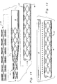
- the stent 10 is preferably then treated to modify its shape memory. Specifically, the stent 10 is placed onto a mandrel M ( Figure 11) by moving the stent 10 axially over a taper T on the mandrel M with sufficient force that the stent 10' in radially expanded configuration is entirely upon the mandrel M.
- the mandrel M is provided with a diameter which matches a desired diameter for the radially expanded configuration of the stent 10'.
- the stent 10' still has a shape memory corresponding to its diameter before it was placed upon the mandrel M. If the stent 10 were removed from the mandrel M, this shape memory would cause the stent 10 to return to its original diameter.
- the stent 10 can be cooled to below a transition temperature so that the stent 10 is in a martensite phase with a lower yield strength.
- the stent 10' with mandrel M preferably still adjacent the stent 10' is subjected to heat treatment from a heat source H until the stent 10' has its temperature elevated up to at least 300°C.
- the stent 10' has its temperature elevated up to a range of between 500°C and 800°C.
- the stent 10' is beneficially held at this elevated temperature for an amount of time necessary for the stent 10' to have its shape memory "erased" and to take on a new shape memory corresponding to the diameter of the mandrel M.
- the stent 10' can then be cooled and removed from the mandrel M. Once removed from the mandrel M, the stent 10' now has its shape memory corresponding to the diameter of the mandrel M and hence will not contract back to its original shape.
- the shape memory for the stent 10' is now configured as desired.
- the stent 10' is cooled such as by placing the stent 10' within a liquid coolant L ( Figure 13).
- the stent 10' transitions into a martensite phase where it can be easily manipulated such as by radially collapsing the stent 10' by forcing the stent 10' through a reduction die R while at the reduced temperature and in the martensite phase.
- the liquid L within the enclosure E must have a temperature below a transition temperature which causes the stent 10 to change from its austenite phase to its martensite phase.
- the stent 10 Once the stent 10 has been radially collapsed to its reduced diameter configuration (see also Figure 7) the stent 10 now has a diameter which facilitates more convenient location within a body lumen.
- the stent 10 maintains its shape memory corresponding to the diameter of the mandrel M when the stent 10' was radially expanded onto the mandrel M and experienced its heat treatment.
- the stent 10 is then placed upon a balloon catheter B with a catheter probe P extending from one end thereof and with a sleeve S overlying the stent 10 (Figure 14).
- the balloon catheter B is coupled to a compressed gas source G through a valve B and the sleeve S is attached to a sleeve retraction device D.
- the stent 10 remains at a temperature below its transition temperature and in a martensite phase for as long as possible before implantation into the body lumen.
- the assembly of stent 10, balloon catheter B and sleeve S are then passed together through the desired body lumen pathways until the assembly is located at the position where implantation of the stent 10 is desired.
- the sleeve retraction device D is utilized to remove the sleeve S from the stent 10 ( Figure 15).
- gas from the compressed gas source G is passed through the valve V and into the balloon catheter B, causing the balloon catheter B to expand and causing the stent 10 to radially expand into the radially expanded stent 10'.
- the stent 10' will then be in physical contact with an inner surface I of the lumen wall W.
- the shape memory of the stent 10' may cause the stent 10' to expand radially without requiring inflation of the balloon catheter B.
- expansion of the balloon catheter B assists the stent 10' in effectively converting to its shape memory diameter adjacent the lumen wall W.
- the balloon catheter B can then be removed and the stent 10' remains within the lumen adjacent the inner surface of the lumen wall W.
- the nickel-titanium stent has been described as having a transformation temperature of, for example, 10°C
- the nickel-titanium stent can also be formed with a transformation temperature somewhere between room temperature (20°C-22°C) and body temperature (37°). Selecting the transformation temperature in, for example, a range of 23°C-36°C, the self-expanding stent can be radially collapsed with a smaller diameter at room temperature without having to use a cooling liquid.
- the stent 10 Because the stent 10 has its transition temperature below normal body temperature, the stent 10 will be in its austenite phase and have enhanced yield strength. Hence, radial forces such as blows to the patient adjacent where the stent 10' has been implanted can be resiliently received by the stent 10' without permanent deformation of the stent 10'. A stronger and more elastic support results with the shape memory and/or superelastic nickel-titanium stent 10' than is provided by stents of other non-shape memory materials.
Abstract
Description
- The following invention relates to surgical stents of a generally cylindrical configuration which can be surgically implanted into a body lumen, such as an artery, and radially expanded. More specifically, this invention relates to radially expandable surgical stents formed from nickel-titanium alloys having a high radial strength for implantation in body lumens which experience radial loads.
- Surgical stents have long been known which can be surgically implanted into a body lumen, such as an artery, to reinforce, support, repair or otherwise enhance the performance of the lumen. For instance, in cardiovascular surgery it is often desirable to place a stent in the coronary artery at a location where the artery is damaged or is susceptible to collapse. The stent, once in place, reinforces that portion of the artery allowing normal blood flow to occur through the artery. One form of stent which is particularly desirable for implantation in arteries and other body lumens is a cylindrical stent which can be radially expanded from a first smaller diameter to a second larger diameter. Such radially expandable stents can be inserted into the artery by being located on a catheter and fed internally through the arterial pathways of the patient until the unexpanded stent is located where desired. The catheter is fitted with a balloon or other expansion mechanism which exerts a radial pressure outward on the stent causing the stent to expand radially to a larger diameter. Such expandable stents exhibit sufficient rigidity after being expanded that they will remain expanded after the catheter has been removed.
- Radially expandable stents come in a variety of different configurations to provide optimal performance to various different particular circumstances. For instance, the patents to Lau (Patent Nos. 5,514,154, 5,421,955, and 5,242,399), Baracci (Patent No. 5,531,741), Gaterud (Patent No. 5,522,882), Gianturco (Patent Nos. 5,507,771 and 5,314,444), Termin (Patent No. 5,496,277), Lane (Patent No. 5,494,029), Maeda (Patent No. 5,507,767), Marin (Patent No. 5,443,477), Khosravi (Patent No. 5,441,515), Jessen (Patent No. 5,425,739), Hickle (Patent No. 5,139,480), Schatz (Patent No. 5,195,984), Fordenbacher (Patent No. 5,549,662), Wiktor (Patent No. 5,133,732) and Pinchasik (Patent No. 5,449,373) and the patent applications EP 0732088 and WO9532757, each include some form of radially expandable stent for implantation into a body lumen.
Among the prior art documents listed above, documents US 5,514,254, EP 0732088, WO 9532757 and US 5,449,373 all disclose radially expandable stents having a configuration comprising circumferential and axial elements, the relative number and form of which determines the properties of the stents, such as degree of radial expansion, axial contraction and/or lengthening, and lateral flexibility. Specific configurations of the stents may result in enhancement or decrease of one or several properties of the stents. For example, document US 5,514,254 discloses the use of circumferential elements disposed in an undulating pattern and linked to each other by only one form of axial elements. This will result in a contraction of the stent upon radial expansion of the latter, unless the circumferential undulating elements are strictly parallel or "in phase". Document EP 0732088 discloses axial elements which are deformed radially outwardly to form projecting barbs for attaching the stent to a body lumen. Clearly, barbs will project outwardly only if there is significant axial contraction of the stent as it is expanded radially. Some limitation of the axial contraction of the stent is provided by the use of different forms of axial elements within a gap between two adjacent circumferential elements. The stent of WO 9532757 is relatively rigid when expanded due to the nitinol elements being joined by fusion welds formed before the frame is annealed, the welding leading to well-known problems of brittleness at fusion regions. The configuration of the latter stent may be viewed as formed by circumferential elements disposed in an undulating pattern and linked by only one form of linear axial elements, contributing to the overall rigidity of the stent. The stent of US 5,449,373 is articulated and includes at least two rigid segments and a flexible connector for connecting adjacent segments. The configuration of this stent may be viewed as formed by circumferential elements determining adjacent gaps therebetween, flexible axial elements being identical and present only in non-adjacent gaps. This configuration tends to result in a stent that has a somewhat non-uniform bending property. - Each of these prior art stents suffer from a variety of drawbacks which make them less than ideal. For instance, many of these stents are formed from stainless steel or other materials which have a relatively low yield strength. Hence, if the body lumen is subjected to radial loads and related radial stresses, the stents are susceptible to collapse or other permanent deformation in an undesirable manner. If such stents are provided with segments of greater thickness to enhance their strength, they become too thick to be effectively collapsed for insertion and later expansion within the body lumen.
- One material for forming higher strength radially expandable surgical stents is a shape memory nickel-titanium alloy. Shape memory nickel-titanium alloys and other shape memory alloys are unique in that they have two distinct solid phases. A high yield strength austenite phase (195-690 MPa) and a lower yield strength martensite phase (70-140 MPa). The material can be selectively transformed between the austenite phase and the martensite phase by altering a temperature of the shape memory nickel-titanium alloy. For instance, it is known to form the nickel-titanium alloy so that the stent is in the martensite phase when chilled to a temperature below body temperature and to be in the austenite phase when the stent is at body temperature.
- Additionally, when such shape memory alloys are stressed beyond their yield strength while in the martensite phase, not to exceed certain maximum amounts of strain, the alloy has a "memory" of its shape before its yield strength in the martensite phase was exceeded so that when the alloy is heated and transformed into its austenite phase it returns to the shape it exhibited before it was plastically deformed in the martensite phase. In radially expandable surgical stents, this shape memory has been used to collapse the stent to a small diameter when in its martensite phase and then heat the stent up to body temperature and transform the stent into its austenite phase where it radially expands back to its original expanded diameter and exhibits a desired strength and size for supporting walls of the body lumen in which it is implanted. Hence, the relatively high yield strength of the shape memory alloy stent in its austenite phase provides beneficial characteristics for supporting the body lumen while the martensite phase for the shape memory alloy stent is utilized to allow the stent to be easily radially contracted and deformed during implantation of the stent.
- While such shape memory nickel-titanium alloy stents are generally effective, known shape memory nickel-titanium stents have exhibited certain deficiencies. For instance, when such prior art shape memory nickel-titanium stents are radially expanded they tend to contract axially, enhancing the difficulty experienced by a surgeon in precisely implanting the stent where desired. Additionally, the limited degree of collapsibility of known prior art shape memory nickel-titanium stents has enhanced the difficulty of their implantation in many body lumens. Accordingly, a need exists for shape memory nickel-titanium alloy stents which have a configuration which beneficially overcomes the drawbacks of known prior art shape memory nickel-titanium alloy stents.
- This invention provides a radially expandable stent formed of shape memory and/or superelastic nickel-titanium alloy which advantageously exhibits little or no contraction along an entire axial length thereof when the stent is expanded radially. The stent includes a series of struts which act as circumferential segments circumscribing the cylindrical contour of the stent. Each strut is aligned with a separate plane perpendicular to a central axis of the cylindrical contour of the stent and parallel to other planes to which adjacent struts are aligned. The stent can have various different numbers of struts joined together to form the stent. However, at least two end struts are provided including a front end strut and a rear end strut which define ends of the cylindrical contour of the stent. At least one intermediate strut is also typically provided between the two end struts.
- Each of these struts can exhibit a wave-like shape as they circumscribe the cylindrical contour of the stent. Thus, each strut has a series of bends which have troughs and crests alternating along the length of each strut. Substantially linear legs extend between each bend. Each trough defines a portion of the strut which is most distant from adjacent struts and each crest defines a portion of the strut closest to adjacent struts. An amplitude of each strut, defined by the distance between the bottom of each trough and the top of each crest is modified when the stent is radially expanded so that the amplitude is decreased.
- The end struts are attached to adjacent intermediate struts by tie bars which act as axial segments connecting the two adjacent struts together. Tie bars can also connect adjacent intermediate struts to each other. Each tie bar attaches to the struts adjacent thereto through a first end of the tie bar and a second end of the tie bar. Both the first end and the second end are located within troughs of the struts. Thus, the tie bars span a gap between adjacent struts at a maximum width portion of the gap. Not all of the gaps are spanned by tie bar axial elements. Rather, separate intermediate circumferential segments can be attached to each other through links which connect to the intermediate segments at locations spaced away from the troughs thereof.
- To further enhance the collapsibility and expandability of the stent as well as an overall strength of the stent, the legs of the struts preferably do not have a constant thickness. Rather, ends of each leg adjacent bends in the struts preferably have a greater thickness than a middle of each leg between the ends of each leg. Also, the bends in the struts preferably have a greater width between an inner radius on a trough side of each bend and an outer radius on a crest side of each bend. This enhanced width of the bends and enhanced thickness of the legs near the ends provides maximum strength for the struts at locations on the struts where stresses are concentrated and fracture of the struts is most likely. Hence, greater resistance to fracture of the struts of the stent is provided.
- Because the legs are preferably substantially linear, the stent can be radially contracted until the adjacent legs of each strut are substantially parallel to each other, potentially to the point where adjacent legs abut each other.
- To form the shape memory and/or superelastic nickel-titanium alloy stent the following basic procedure can be followed. Initially, a cylindrical tube of the desired nickel-titanium alloy is provided having a diameter intermediate between a desired expanded configuration and a desired collapsed configuration. This cylindrical tube is cut until only the series of circumferential segments and axial segments remain defining the generally cylindrical contour of the stent. The stent is then forced onto a mandrel having a diameter matching a desired radially expanded diameter until the stent has been expanded to the desired radially expanded diameter. The stent is then heat treated at a temperature of at least 350°C until the shape memory of the stent in its austenite phase has a diameter matching that of the mandrel and the transformation temperature is set as desired. For instance, a transformation temperature of about 10°C allows the stent to be fully in its austenite phase at body temperatures. The stent can then be removed from the mandrel.
- The stent can be cooled until it transforms into its martensite phase. While in the martensite phase, the stent is radially collapsed down to its desired collapsed diameter configuration. When the stent is ready for implantation within a body lumen, the stent in its collapsed configuration is inserted with a catheter to the desired implantation site. The body temperature of the patient causes the stent to transform into its austenite phase and the shape memory of the nickel-titanium alloy causes the stent to expand radially to the desired radially expanded configuration. To ensure proper radial expansion of the stent from its collapsed configuration to its expanded configuration, a sleeve can be placed over an outer surface of the stent until the stent is in the desired position and a balloon can be located within an interior of the stent which can be radially expanded to assist the stent in fully expanding to its radially expanded shape memory configuration. The relatively high yield strength elastic austenite phase nickel-titanium stent is then in place within the body lumen to support the body lumen while resisting deformation when receiving radial loads. The transformation temperature of the nickel-titanium alloy can also be selected to be in a range of, for example, 23°C to 36°C, between room temperature (20-22°C) and body temperature (37°). As a result, the stent can be radially collapsed without the need for a coolant.
- Accordingly, a primary object of the present invention is to provide a radially expandable and contractible nickel-titanium shape memory stent which does not contract axially when expanded radially.
- Another object of the present invention is to provide a surgical stent which exhibits little or no axial contraction at ends thereof when expanded radially.
- Another object of the present invention is to provide a stent which exhibits sufficient flexibility to allow a central axis thereof to bend, especially when the stent is being threaded through arterial pathways within a patient.
- Another object of the present invention is to provide a nickel-titanium surgical stent which is formed from a series of struts which form circumferential segments circumscribing a cylindrical contour of the stent, the individual struts joined together by tie bars which act as axial segments restraining the struts from contracting together when expanded radially.
- Another object of the present invention is to provide a surgical stent which has a configuration which lends itself to manufacture from a variety of techniques including machining, photo-etching, laser cutting and other precision low cost techniques.
- Another object of the present invention is to provide a surgical stent which has a configuration which exhibits the strength necessary to support a body lumen when implanted therein and radially expanded.
- Another object of the present invention is to provide a surgical stent which can be located within a body lumen by a surgeon with a high degree of locational precision.
- Another object of the present invention is to provide a nickel-titanium surgical stent which can be radially expanded to over four times its radially contracted diameter, does not substantially contract axially when radially expanded and which has sufficient flexibility to match a flexibility of a guide wire of a stent positioning catheter utilized to position the stent.
- Another object of the present invention is to provide a shape memory surgical stent which can be radially contracted when in a martensite phase for ease in implantation within a body lumen and later radially expanded to a "memorized" shape when the stent transitions into an austenite phase.
- Another object of the present invention is to provide a surgical stent which exhibits a high yield strength (i.e. at least 195 MPa and up to 690 MPa) such that the stent resists plastic deformation when radial collapsing loads are encountered, such as impacts to the patient adjacent the body lumen where the stent is implanted.
- Another object of the present invention is to provide a surgical stent which can be implanted in body lumens on extremities of a patient without substantial risk of collapse or other damage to the stent when blows are experienced by the patient adjacent the site of surgical implantation of the stent.
- Another object of the present invention is to provide a nickel-titanium surgical stent which has a configuration which allows the stent to be radially expanded from a radially collapsed configuration to a radially expanded configuration up to four or more times the size of its collapsed configuration without segments of the stent experiencing fractures.
- Other further objects of the present invention will become apparent from a careful reading of the included description and claims and from a review of the drawing figures.
-
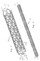
- Figure 1 is a perspective view of a nickel-titanium stent of a basic configuration in a radially expanded configuration.
- Figure 2 is a perspective view of the basic stent of Figure 1 in a radially collapsed configuration.
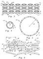
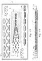
- Figure 3 is a cylindrical projection of the basic stent of Figures 1 and 2.
- Figure 4 is an end view of that which is shown in Figure 1.
- Figure 5 is an end view of that which is shown in Figure 2.
- Figure 6 is a detail of a portion of that which is shown in Figure 3 with some of the struts shown therein featuring legs with variable thicknesses to enhance a strength of the struts.
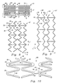
- Figure 7 is a cylindrical projection of a portion of a radially collapsed stent similar to that which is shown in Figure 1 but without width enhancement adjacent bends in the struts.
- Figure 8 is a cylindrical projection of a portion of that which is shown in Figure 3 with said stent partially radially expanded.
- Figure 9 is a cylindrical projection of that which is shown in Figure 8 after full radial expansion of the stent.
- Figure 10 is a detail of a portion of that which is shown in Figure 3 except that certain axial segments are configured as straight links.
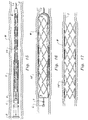
- Figure 11 is a top plan view of a series of steps involved in the process of forcing a stent, such as that which is shown in Figures 1-5, onto a mandrel for enhancing a radial diameter of the stent.
- Figure 12 is a top plan view of a heat applying step involved in altering a shape memory for the stent shown therein.
- Figure 13 is a front elevation view of a series of steps involved in radially collapsing the stent from the radially expanded configuration to the radially collapsed configuration while the stent is cooled below a transformation temperature and in a martensite phase.
- Figure 14 is a top plan view of the stent of Figures 1-5 within a surgical implantation apparatus with portions of the apparatus cut away to reveal interior details thereof.
- Figure 15 is a sectional view of a body lumen with the stent of Figures 1-5 in the process of being implanted with the implantation apparatus of Figure 14.
- Figure 16 is a sectional view similar to that which is shown in Figure 15 revealing an intermediate step in the implantation of the stent of Figures 1-5.
- Figure 17 is a sectional view of a body lumen after the stent of Figures 1-5 has been successfully implanted and radially expanded within the body lumen.
-
- Referring to the drawings wherein like reference numerals represent like parts throughout,
reference numeral 10 is directed to a radially expandable and contractible surgical stent formed from a shape memory and/or superelastic material such as a nickel-titanium alloy. As a result, the nickel-titanium stent is also self-expanding. Thestent 10 is cylindrical in contour with a series of struts 20 (Figure 3) forming circumferential segments of thestent 10 which exhibit a wave-like contour. Thestruts 20 can hence be collapsed to reduce a radius of thestent 10 and expanded to increase a radius of the stent 10 (along Arrow R of Figure 1). An axial length, along arrow A, remains constant when thestent 10 is radially collapsed and expanded along arrow R. - In essence, and with particular reference to Figures 1-6, the
stent 10 has the following basic configuration. A series ofstruts 20 having a wave-like contour with a series of troughs and crests extend circumferentially, along arrow C, at a location of substantially constant radial distance away from acentral axis 2.Gaps 60 are located between each pair ofadjacent struts 20. Thestruts 20 provide circumferential segments for thestent 10. Axial segments in the form of tie bars 70 andangled links 80 span thegaps 60 and joinadjacent struts 20 together. The tie bars 70 attach toadjacent struts 20 at attachment bends 50 in thestruts 20 and on atrough side 52 of the attachment bends 50. Theangled links 80, or optionally the straight links 90 (Figure 10) attach toadjacent struts 20 at attachment bends 50 on acrest side 54 of the attachment bends 50. In this way, radial expansion, along arrow R, does not cause contraction of an axial length, along arrow A, of thestent 10. Eachgap 60 is either spanned only bytie bars 70 or spanned only byangled links 80 orstraight links 90. Thegaps 60 with tie bars 70 alternate with thegaps 60 spanned by theangled links 80 orstraight links 90. - The wave-like contour of each
strut 20 preferably is formed from a series of substantiallystraight legs 30 extending betweenfree bends 40 and attachment bends 50. The free bends 40 do not have any tie bars 70, angledlinks 80 orstraight links 90 coupled thereto. The attachment bends 50 have either atie bar 70, angledlink 80 orstraight link 90 attached thereto. Athickness 36 of thelegs 30 can be enhanced adjacent ends 32 of thelegs 30 and awidth 46 of thefree bends 40 and awidth 56 of the attachment bends 50 can be enhanced with respect to a thickness of the middle 34 of thelegs 30, such that regions of potential fracture of thestruts 20 are strengthened. - Because the
stent 10 is formed from a shape memory and/or superelastic nickel-titanium material thestent 10' has a radially expanded configuration (Figure 1) when thestent 10' is in a position corresponding to its shape memory and when thestent 10' is in an austenite phase. Thestent 10 can be cooled below a transition temperature to undergo a phase change into a martensite phase and then be radially collapsed to its radially collapsed configuration (Figure 2) without losing its shape memory. It is also contemplated that the stent can be radially collapsed or contracted while also in the austenitic state at, for example, room temperature (20-22°C). Hence, when thestent 10' is heated above its transition temperature and converted back into its austenite phase it tends to return back to its radially expanded configuration (Figure 1) and exhibits a higher yield strength corresponding to its austenite phase. - More specifically, and with particular reference to Figures 3 and 6, details of the configuration of the
struts 20 of thestent 10 are provided. Eachstrut 20 is preferably similar in size and shape to all of theother struts 20 of thestent 10. Thestruts 20 are integrally formed with other portions of thestent 10 from a shape memory and/or superelastic material, such as a nickel-titanium alloy, having the desired characteristics for surgical implantation into a body lumen. Specifically, known nickel-titanium alloys have an austenite phase with a high yield strength (195-690 MPa) and a martensite phase with a lower yield strength (70-140 MPa) with the material having a shape memory which causes the stent to return to its memorized austenite phase shape when the temperature of the stent is above a transition temperature between the martensite phase and the austenite phase. The transition temperature is selected to be below typical body temperature so that thestent 10 can be easily contracted when cooled below the transition temperature but will be in its austenite phase once implanted and at body temperature. - Each
strut 20 extends as a circumferential segment, along arrow C (Figures 1 and 3-5), and has a wave-like pattern as thestrut 20 circumscribes the cylindrical contour of thestent 10. The wave-like contour of thestent 20 is preferably uniform such that thestrut 20 has a uniform amplitude 22 (Figure 6) and auniform wavelength 24. Thisamplitude 22 andwavelength 24 are altered when a diameter of thestent 10 is modified. - Each
strut 20 is preferably formed from a series of substantiallylinear legs 30. While thelegs 30 are substantially linear, they may in fact curve slightly to match the cylindrical contour of thestent 10. Thelegs 30 have ends 32 where eachleg 30 is attached to adjacentfree bends 40 or attachment bends 50. Eachleg 30 also has a middle 34 halfway between each of the ends 32. Eachleg 30 has athickness 36 which is measured in a direction substantially perpendicular to a direction that theleg 30 extends between the ends 32. - In one form of this invention the
struts 20 are formed fromlegs 30 which have a uniform thickness 36 (Figure 3). In a preferred form of this invention, however, thestruts 20 feature legs 30' (Figure 6) which have a thickness 36' which is variable. Specifically, the middle 34' of the legs 30' has a lesser thickness 36' than do the ends 32' of the legs 30'. When thestruts 20 are radially expanded (along Arrow R of Figures 1, 4 and 5) little stress is experienced by thelegs 30 of thestruts 20 at the middle 34. In contrast, the ends 32 have a greater amount of stress because of the location of the adjacentfree bends 40 and attachment bends 50. By enhancing the thickness 36' of the legs 30' so that the ends 32' have a greater thickness 36' than the middle 34' of the legs 30', the legs 30' are less susceptible to fracture resulting from the stress concentrations near the ends 32'. - Each
leg 30 preferably has a similar length toother legs 30 throughout thestrut 20 and throughout thestent 10. The greater the length of thelegs 30, the greater the amount of radial expansion possible by thestent 10. However, if thelegs 30 are too long than they will causestruts 20 to abutadjacent struts 20 when radially collapsed (as shown in Figures 1 and 7) and prevent complete radial contraction of thestent 10. Hence, thelegs 30 preferably have a length substantially equal to one-half of the distance between adjacent struts 20 (measured trough to trough) to prevent abutting of thelegs 30 ofadjacent struts 20. - The free bends 40 are distinct from the attachment bends 50 in that the
free bends 40 join twoadjacent legs 30 together only, without any axial segments adjacent thereto connecting toadjacent struts 20. The attachment bends 50, in contrast, join twoadjacent legs 30 together and also attach to either atie bar 70, anangled link 80 or a straight link 90 (Figure 10) which spans anadjacent gap 60 and attaches to anadjacent strut 20. The free bends 40 include aninner radius 42 on an inside of thebend 40 and defining a trough and anouter radius 44 on an outside of thebend 40 and defining a crest. - The
width 46 of thefree bend 40 is defined as a distance between theinner radius 42 and theouter radius 44. Theinner radius 42 andouter radius 44 are rounded sufficiently to minimize stress concentrations adjacent thefree bends 40 so that thefree bends 40 do not provide a preferred location for fracture of thestruts 20 of thestent 10. Additionally, an as shown in Figure 6, some free bends 40' can be provided with anenhanced width 46, especially when such free bends 40' are joining adjacent legs 30' having ends 32' of enhanced thickness 36'. With thewidth 46 provided with an enhanced size, the ability of the free bends 40' of thestrut 20 to resist fracture is enhanced. Alternatively, thefree bends 40 can be provided with awidth 46 substantially matching thethickness 36 of thelegs 30. - The attachment bends 50 include a
trough side 42 on an inside of eachattachment bend 50 and acrest side 54 on an outer side of eachattachment bend 50. Awidth 56 is defined as a distance between thetrough side 52 and thecrest side 54. As with the free bends 40, the attachment bends 50 can be provided with anenhanced width 56 which is greater than thewidth 46 of thelegs 30 to enhance a strength of thestruts 20 at the attachment bends 50. Alternatively, the attachment bends 50 can have awidth 56 which matches athickness 36 of the legs 30 (as shown in Figures 2). - In Figure 6, some of the struts 20 (at a right side of Figure 6) exhibit attachment bends 50' which do not exhibit an
enhanced width 56 but rather which narrow to a width less than thethickness 36 of thelegs 30 adjacent to the attachment bend 50'. Hence, awidth 56 between a trough side 52' and a crest side 54' is reduced. Such an arrangement for the attachment bend 50' provides another alternative arrangement for configuration of the attachment bends 50 within thestruts 20. - As shown in Figure 7, the
struts 20 can be radially collapsed to an extent where thelegs 30 of thestruts 20 are substantially parallel to each other and oriented axially, along arrow A. If thelegs 30 are provided with enhanced thickness 36' adjacent the ends 32' (as shown in Figure 6), clearance exists for such enhanced thickness 36' within theleg 30 pattern displayed in Figure 7. This is partially because such thickness 36' enhancement adjacent the end 32' only occurs on a side of the legs 30' which transition into theouter radius 44 orcrest side 54 and not theinner radius 42 ortrough side 52. Hence, enhancing a thickness of thelegs 30, at least a limited amount, does not restrict an ability of thestruts 20 to radially collapse along with radial collapse of thestent 10. - Preferably, the
stent 10 is chilled below a transition temperature such that thestent 10 is in a martensite phase when radially collapsed as shown in Figure 7. An austenite phase for thestent 10 can either be provided as shown in Figure 8 byreference numeral 10' or with a greater amount of radial expansion as shown in Figure 9 byreference numeral 10". Even though thestent 10 shown in Figure 7 is radially collapsed and in a martensite phase, it has a shape memory corresponding to thestent 10' of Figure 8 or thestent 10" of Figure 9, depending on the configuration and shape memory provided to thestent 10. - Radial expansion of the
stent 10 by a factor of over four times can be achieved in certain circumstances. For instance, stents with a circumference of 0.319 cm (.1256 inches) can be radially expanded to have a circumferential length of 1.572 cm (.6189 inched and stents having a circumferential length of 0.5067 cm (.1995 inches) can be radially expanded to up to 2.1958 cm (.8645 inches) in circumferential length. - With continuing reference to Figures 3 and 6-10, details of the
gaps 60 and axial segments such as tie bars 70, angledlinks 80 andstraight links 90 are described. Preferably, eachstrut 20 is spaced fromadjacent struts 20 by agap 60. Eachgap 60 does not have a constant width but rather has a width which oscillates between minimums 62 andmaximums 64. Each minimum 62 is defined as an axial distance between aligned crest sides 54 of attachment bends 50 or alignedouter radii 44 offree bends 40 ofadjacent struts 20. Each maximum 64 is defined as an axial distance between axially aligned trough sides 52 of attachment bends 50 orinner radii 42 offree bends 40 ofadjacent struts 20. Eachgap 60 either has axial segments in the form of tie bars 70 attachingstruts 20 adjacent thegap 60 together or has angledlinks 80 orstraight links 90 spanning thegap 60 and joiningadjacent struts 20 together. Ingaps 60 which feature tie bars 70, the tie bars 70 join to attachment bends 50 ofadjacent struts 20 attrough sides 52 of eachattachment bend 50. Eachtie bar 70 includes afirst end 72 attached to thetrough side 52 of one of the attachment bends 50 of one of thestents 20 and a second end 74 attached to atrough side 52 of anattachment bend 50 of theother strut 20. -
Gaps 60 which featureangled links 80 orstraight links 90 spanning saidgaps 60 and attach toadjacent struts 20 atcrest sides 54 of attachment bends 50 ofadjacent struts 20. Eachangled link 80 includes afirst arm 82 and asecond arm 84 attached together by anelbow 86. Thefirst arm 82 attaches to thecrest side 54 of theattachment bend 50 of one of thestruts 20 and thesecond arm 84 of theangled link 80 attaches to thecrest side 54 of theattachment bend 50 of theother strut 20 on the other side of thegap 60. - Similarly, the straight link 90 (Figure 10) includes a
first tip 92 attached to acrest side 54 of anattachment bend 50 of one of thestruts 20 adjacent thegap 60 and asecond tip 94 attached to thecrest side 54 of theattachment bend 50 of theother strut 20 on an opposite side of thegap 60. Theangled links 80 andstraight links 90 essentially span thegap 60 at a minimum 62 in thegap 60. In contrast, the tie bars 70 span thegap 60 atmaximums 64 of thegap 60. Hence, when thestruts 20 are radially expanded and theiramplitude 22 is reduced and theirwavelength 24 is increased, an average width ofgaps 60 spanned by the tie bars 70 is increased slightly and an average width of thegap 60 spanned by theangled links 80 orstraight links 90 is decreased slightly. A net result is that an overall axial length of thestent 10 between a front end 12 and a rear end 14 (Figure 3) remains constant regardless of the radial configuration of thestent 10. Theangled links 80 are configured to allow thefirst arm 82 andsecond arm 84 to flex somewhat about theelbow 86 to provide a degree of flexibility to thestent 10. When thestent 10 is collapsed and being inserted into a body lumen (Figure 7) angledlinks 80 are desirable to provide enhanced flexibility to thestent 10. - While Figures 1-10 show the
angled links 80 andstraight links 90 offset circumferentially with respect to locations of thetie bar 70, an acceptable alternative arrangement is to have the angledlinks 80 orstraight links 90 axially aligned along a common line with the tie bars 70. - With particular reference to Figures 11 and 12, details of the formation of the
stent 10 are disclosed. Initially, thestent 10 is in the form of a solid cylindrical tube of the appropriate shape memory and/or superelastic material, such as a nickel-titanium alloy. Preferably, a diameter of this original tube of material is intermediate between a desired collapsed configuration diameter and a desired expanded configuration diameter. The tube is then processed, such as by laser cutting, to remove material where it is not needed such that the tube is reduced to thestent 10 having the series of wave-like struts 20 circumferentially surrounding the cylindrical contour of thestent 10 and a series of axial segments such as tie bars 70, angledlinks 80 or straight links 90 (Figures 1-10) joining theadjacent struts 20 together. - The
stent 10 is preferably then treated to modify its shape memory. Specifically, thestent 10 is placed onto a mandrel M (Figure 11) by moving thestent 10 axially over a taper T on the mandrel M with sufficient force that thestent 10' in radially expanded configuration is entirely upon the mandrel M. The mandrel M is provided with a diameter which matches a desired diameter for the radially expanded configuration of thestent 10'. Once upon the mandrel M, thestent 10' still has a shape memory corresponding to its diameter before it was placed upon the mandrel M. If thestent 10 were removed from the mandrel M, this shape memory would cause thestent 10 to return to its original diameter. To enhance the ease with which thestent 10 is placed upon the mandrel M, thestent 10 can be cooled to below a transition temperature so that thestent 10 is in a martensite phase with a lower yield strength. - To alter the shape memory of the
stent 10', thestent 10' with mandrel M preferably still adjacent thestent 10' is subjected to heat treatment from a heat source H until thestent 10' has its temperature elevated up to at least 300°C. Preferably, thestent 10' has its temperature elevated up to a range of between 500°C and 800°C. Thestent 10' is beneficially held at this elevated temperature for an amount of time necessary for thestent 10' to have its shape memory "erased" and to take on a new shape memory corresponding to the diameter of the mandrel M. Thestent 10' can then be cooled and removed from the mandrel M. Once removed from the mandrel M, thestent 10' now has its shape memory corresponding to the diameter of the mandrel M and hence will not contract back to its original shape. The shape memory for thestent 10' is now configured as desired. - With respect to Figures 13-17, details in the steps involved in radially collapsing the
stent 10' down to acollapsed stent 10 for implantation within a body lumen is described. Initially, thestent 10' is cooled such as by placing thestent 10' within a liquid coolant L (Figure 13). Thestent 10' transitions into a martensite phase where it can be easily manipulated such as by radially collapsing thestent 10' by forcing thestent 10' through a reduction die R while at the reduced temperature and in the martensite phase. The liquid L within the enclosure E must have a temperature below a transition temperature which causes thestent 10 to change from its austenite phase to its martensite phase. Once thestent 10 has been radially collapsed to its reduced diameter configuration (see also Figure 7) thestent 10 now has a diameter which facilitates more convenient location within a body lumen. Thestent 10 maintains its shape memory corresponding to the diameter of the mandrel M when thestent 10' was radially expanded onto the mandrel M and experienced its heat treatment. - The
stent 10 is then placed upon a balloon catheter B with a catheter probe P extending from one end thereof and with a sleeve S overlying the stent 10 (Figure 14). Preferably, the balloon catheter B is coupled to a compressed gas source G through a valve B and the sleeve S is attached to a sleeve retraction device D. Preferably, thestent 10 remains at a temperature below its transition temperature and in a martensite phase for as long as possible before implantation into the body lumen. The assembly ofstent 10, balloon catheter B and sleeve S are then passed together through the desired body lumen pathways until the assembly is located at the position where implantation of thestent 10 is desired. - The sleeve retraction device D is utilized to remove the sleeve S from the stent 10 (Figure 15). Once the sleeve S has been removed, gas from the compressed gas source G is passed through the valve V and into the balloon catheter B, causing the balloon catheter B to expand and causing the
stent 10 to radially expand into the radially expandedstent 10'. Thestent 10' will then be in physical contact with an inner surface I of the lumen wall W. The shape memory of thestent 10' may cause thestent 10' to expand radially without requiring inflation of the balloon catheter B. However, expansion of the balloon catheter B assists thestent 10' in effectively converting to its shape memory diameter adjacent the lumen wall W. The balloon catheter B can then be removed and thestent 10' remains within the lumen adjacent the inner surface of the lumen wall W. - Although the nickel-titanium stent has been described as having a transformation temperature of, for example, 10°C, the nickel-titanium stent can also be formed with a transformation temperature somewhere between room temperature (20°C-22°C) and body temperature (37°). Selecting the transformation temperature in, for example, a range of 23°C-36°C, the self-expanding stent can be radially collapsed with a smaller diameter at room temperature without having to use a cooling liquid.
- Because the
stent 10 has its transition temperature below normal body temperature, thestent 10 will be in its austenite phase and have enhanced yield strength. Hence, radial forces such as blows to the patient adjacent where thestent 10' has been implanted can be resiliently received by thestent 10' without permanent deformation of thestent 10'. A stronger and more elastic support results with the shape memory and/or superelastic nickel-titanium stent 10' than is provided by stents of other non-shape memory materials. - Moreover, having thus described the invention is should be apparent that various modifications to this invention could be resorted to without departing from the scope of this invention. This detailed description of the preferred embodiments of this invention is provided to enable one skilled in the art to practice this invention and to disclose a best mode for practicing this invention but is not intended to limit in any way the scope of the claims to this invention.
Claims (18)
- A radially expandable surgical stent (10) for implantation into a body lumen, said stent having a generally cylindrical contour both before and after radial expansion thereof, said stent comprising in combination:characterised in that said one gap has only one form of axial segment spanning at least one part thereof, said one axial segment being connected to the circumferential segments at locations thereon at least as close to one of the troughs as to one of the crests, and in that the said other gap in the other adjacent pair of circumferential segments has only another form of axial segment spanning at least one part thereof, said other axial segment being connected between at least one pair of adjacent crests.a plurality of circumferential segments (20) and axial segments (70, 80, 90) formed from a shape memory and/or superelastic nickel-titanium alloy;said stent including at least three adjacently spaced circumferential segments forming at least two pairs of adjacent circumferential segments, each said circumferential segment extending in a substantially circumferential direction around said cylindrical contour of said stent;each circumferential segment including a series of bends (40, 50) therein, each said bend including a trough (52) and a crest (54), said trough defining a portion of said bend where said trough is more distant from an adjacent trough of an adjacent circumferential segment than other portions of said bend, said crest defining a portion of said bend where said crest is closer to an adjacent crest of an adjacent circumferential segment than other portions of said bend;one pair of adjacent circumferential segments being orientated adjacent each other to define one gap (60) therebetween and another adjacent pair of adjacent circumferential segments being orientated adjacent each other to define another gap therebetween,
- The stent of claim 1, wherein said axial segments spanning said one gap maintain their length.
- The stent of claim 2, wherein said axial segments span said one gap and link to said circumferential segments substantially at said troughs in said circumferential segments.
- The stent of claim 3, wherein each said circumferential segment is spaced from adjacent circumferential segments by gaps such that a number of gaps equals a number of circumferential segments minus one, said gaps including odd numbered gaps and even numbered gaps with each said odd numbered gap having said axial segments attached to adjacent said circumferential segments at troughs in said circumferential segments and each said even numbered gap having axial segments attached to adjacent said circumferential segments at said crests in said circumferential segments.
- The stent of any one of the preceding claims, wherein said circumferential segments are formed from a plurality of substantially linear legs (30) extending between each bend in said circumferential segments.
- The stent of claim 5, wherein at least one (30') of said legs exhibits a variable thickness with a lesser thickness (36') near a middle (34') of said leg and a greater thickness at ends (32') of said leg.
- The stent of claim 5 or 6, wherein said bends include attachment bends (50) where axial segments are attached to said circumferential segments and free bends (40) without axial segments attached thereto, at least one of said attachment bends (50') having a greater width between a trough side of said attachment bend and a crest side of said bend than a thickness of said legs at middles of said legs.
- The stent of claim 7, wherein said free bends have a greater width (40') between an inner radius of said free bends and an outer radius of said free bends than said thickness of said middles of said legs.
- The stent of any one of the preceding claims, wherein said stent is self-expanding.
- The stent of any one of the preceding claims, wherein said axial segments spanning said one gap are offset with respect to axial segments in adjacent said gaps.
- The sent of any one of the preceding claims, wherein said axial segments spanning said one gap are aligned with axial segments spanning adjacent said gaps.
- A method for forming the radially expandable surgical stent of any one of the preceding claims from a shape memory and/or superelastic nickel-titanium alloy such that said stent has a radially expanded configuration (10', 10") when said stent is unstressed and said stent is in an austenite phase when said stent is at or near body temperature, the method including the steps of:cutting a cylindrical tube of nickel-titanium alloy material, the cylindrical tube of material having a diameter intermediate between a desired radially expanded diameter and a desired radially contracted diameter;removing material from the cylindrical tube such that only a plurality of wave-like circumferential segments circumscribing a cylindrical contour of the stent and plurality of axial segments spanning gaps between adjacent circumferential segments remain on the stent;forcing the stent (10) onto a tapering mandrel (M) having a lesser diameter end with a diameter similar to a diameter of the stent and a greater diameter end with a diameter similar to the desired radially expanded diameter for the stent until the stent (10') is expanded to the desired radially expanded diameter and is located upon the mandrel;heating the stent while the stent is on the mandrel to a temperature of at least 350°C;holding the stent at a temperature of at least 350°C until a shape memory for the stent has changed to a diameter corresponding to the diameter of the mandrel;removing the stent from the mandrel;cooling the stent to below a transformation temperature such that the stent enters a martensite phase; andapplying a radially contracting force to the stent until the stent is radially contracted to the desired radially contracted diameter.
- The radially expandable surgical stent of any one of the preceding claims, formed of a shape memory and/or superelastic nickel-titanium alloy, the stent comprising in combination:a substantially cylindrical radially collapsed configuration (10) when said stent is at first temperature corresponding to a martensite phase for the alloy;a substantially cylindrical radially expanded configuration (10', 10") when said stent is at second temperature corresponding to a austenite phase for the alloy;said second temperature higher than said first temperature;said stent having a larger diameter when said stent is in said radially expanded configuration than when said stent is in radially collapsed configuration; andsaid collapsed configuration having a diameter less than one third an amount of said larger diameter when said stent is in said radially expanded configuration.
- The shape memory stent of claim 13, wherein said collapsed configuration has a diameter less than one fourth of an amount of said larger diameter when said stent is in said radially expanded configuration.
- The shape memory stent of claim 13 or 14, wherein said stent is formed from a plurality of wave-like circumferential segments with a plurality of substantially linear legs extending between bends in said circumferential segments, said legs having ends (32) adjacent said bends and a middle (34) between said ends, at least one (30') of said legs having a middle (34') with a thickness less than a thickness of said at least one leg at said ends (32') of said at least one leg, such that said at least one leg exhibits greater strength adjacent said ends.
- The shape memory stent of any one of claims 13 to 15 wherein said stent includes means to flex when in said collapsed configuration, said flexing means including said stent formed from a plurality of wave-like circumferential segments with gaps between adjacent said circumferential segments, at least one of said gaps having at least one form of axial segment (80) spanning said at least one gap, said at least one form of axial element including means to bend and allow a width of said at least one gap to be modified, allowing said stent to flex.
- The shape memory stent of any one of claims 13 to 16, wherein said stent includes a plurality of wave-like circumferential segments including a series of substantially linear legs joined together at bends in each said circumferential segment.
- The shape memory stent of any one of claims 13 to 17, wherein said collapsed configuration of said stent results in said legs of said circumferential segments being orientated substantially parallel to each other in a substantially axial direction.
Applications Claiming Priority (3)
| Application Number | Priority Date | Filing Date | Title |
|---|---|---|---|
| US08/939,703 US6042606A (en) | 1997-09-29 | 1997-09-29 | Radially expandable non-axially contracting surgical stent |
| US939703 | 1997-09-29 | ||
| PCT/US1998/020451 WO1999016387A1 (en) | 1997-09-29 | 1998-09-29 | Radially expandable nickel-titanium surgical stent |
Publications (2)
| Publication Number | Publication Date |
|---|---|
| EP1018986A1 EP1018986A1 (en) | 2000-07-19 |
| EP1018986B1 true EP1018986B1 (en) | 2004-01-21 |
Family
ID=25473590
Family Applications (1)
| Application Number | Title | Priority Date | Filing Date |
|---|---|---|---|
| EP98949641A Expired - Lifetime EP1018986B1 (en) | 1997-09-29 | 1998-09-29 | Radially expandable nickel-titanium surgical stent |
Country Status (9)
| Country | Link |
|---|---|
| US (2) | US6042606A (en) |
| EP (1) | EP1018986B1 (en) |
| JP (1) | JP4104041B2 (en) |
| KR (1) | KR20010030765A (en) |
| AU (1) | AU736981B2 (en) |
| CA (1) | CA2304578C (en) |
| DE (1) | DE69821251T2 (en) |
| ES (1) | ES2214735T3 (en) |
| WO (1) | WO1999016387A1 (en) |
Families Citing this family (440)
| Publication number | Priority date | Publication date | Assignee | Title |
|---|---|---|---|---|
| CA2079417C (en) * | 1991-10-28 | 2003-01-07 | Lilip Lau | Expandable stents and method of making same |
| JP4636634B2 (en) * | 1996-04-26 | 2011-02-23 | ボストン サイエンティフィック サイムド,インコーポレイテッド | Intravascular stent |
| US6235053B1 (en) * | 1998-02-02 | 2001-05-22 | G. David Jang | Tubular stent consists of chevron-shape expansion struts and contralaterally attached diagonal connectors |
| US6783543B2 (en) | 2000-06-05 | 2004-08-31 | Scimed Life Systems, Inc. | Intravascular stent with increasing coating retaining capacity |
| US6241760B1 (en) * | 1996-04-26 | 2001-06-05 | G. David Jang | Intravascular stent |
| US5954743A (en) * | 1996-04-26 | 1999-09-21 | Jang; G. David | Intravascular stent |
| US20040106985A1 (en) * | 1996-04-26 | 2004-06-03 | Jang G. David | Intravascular stent |
| US6666883B1 (en) | 1996-06-06 | 2003-12-23 | Jacques Seguin | Endoprosthesis for vascular bifurcation |
| US8728143B2 (en) * | 1996-06-06 | 2014-05-20 | Biosensors International Group, Ltd. | Endoprosthesis deployment system for treating vascular bifurcations |
| US7238197B2 (en) * | 2000-05-30 | 2007-07-03 | Devax, Inc. | Endoprosthesis deployment system for treating vascular bifurcations |
| US7686846B2 (en) * | 1996-06-06 | 2010-03-30 | Devax, Inc. | Bifurcation stent and method of positioning in a body lumen |
| US8353948B2 (en) * | 1997-01-24 | 2013-01-15 | Celonova Stent, Inc. | Fracture-resistant helical stent incorporating bistable cells and methods of use |
| US8663311B2 (en) * | 1997-01-24 | 2014-03-04 | Celonova Stent, Inc. | Device comprising biodegradable bistable or multistable cells and methods of use |
| US5827321A (en) * | 1997-02-07 | 1998-10-27 | Cornerstone Devices, Inc. | Non-Foreshortening intraluminal prosthesis |
| US20040267350A1 (en) * | 2002-10-30 | 2004-12-30 | Roubin Gary S. | Non-foreshortening intraluminal prosthesis |
| GB9703859D0 (en) * | 1997-02-25 | 1997-04-16 | Plante Sylvain | Expandable intravascular stent |
| US6309414B1 (en) | 1997-11-04 | 2001-10-30 | Sorin Biomedica Cardio S.P.A. | Angioplasty stents |
| US6190406B1 (en) * | 1998-01-09 | 2001-02-20 | Nitinal Development Corporation | Intravascular stent having tapered struts |
| US6533807B2 (en) | 1998-02-05 | 2003-03-18 | Medtronic, Inc. | Radially-expandable stent and delivery system |
| US6395019B2 (en) | 1998-02-09 | 2002-05-28 | Trivascular, Inc. | Endovascular graft |
| US6132461A (en) * | 1998-03-27 | 2000-10-17 | Intratherapeutics, Inc. | Stent with dual support structure |
| US6558415B2 (en) * | 1998-03-27 | 2003-05-06 | Intratherapeutics, Inc. | Stent |
| US7208011B2 (en) * | 2001-08-20 | 2007-04-24 | Conor Medsystems, Inc. | Implantable medical device with drug filled holes |
| US6241762B1 (en) * | 1998-03-30 | 2001-06-05 | Conor Medsystems, Inc. | Expandable medical device with ductile hinges |
| US7208010B2 (en) | 2000-10-16 | 2007-04-24 | Conor Medsystems, Inc. | Expandable medical device for delivery of beneficial agent |
| US6461380B1 (en) | 1998-07-28 | 2002-10-08 | Advanced Cardiovascular Systems, Inc. | Stent configuration |
| US6755856B2 (en) * | 1998-09-05 | 2004-06-29 | Abbott Laboratories Vascular Enterprises Limited | Methods and apparatus for stenting comprising enhanced embolic protection, coupled with improved protection against restenosis and thrombus formation |
| US6682554B2 (en) | 1998-09-05 | 2004-01-27 | Jomed Gmbh | Methods and apparatus for a stent having an expandable web structure |
| US7887578B2 (en) | 1998-09-05 | 2011-02-15 | Abbott Laboratories Vascular Enterprises Limited | Stent having an expandable web structure |
| US7815763B2 (en) | 2001-09-28 | 2010-10-19 | Abbott Laboratories Vascular Enterprises Limited | Porous membranes for medical implants and methods of manufacture |
| DE19840645A1 (en) * | 1998-09-05 | 2000-03-09 | Jomed Implantate Gmbh | Stent |
| US20020019660A1 (en) * | 1998-09-05 | 2002-02-14 | Marc Gianotti | Methods and apparatus for a curved stent |
| US6293967B1 (en) | 1998-10-29 | 2001-09-25 | Conor Medsystems, Inc. | Expandable medical device with ductile hinges |
| US8092514B1 (en) * | 1998-11-16 | 2012-01-10 | Boston Scientific Scimed, Inc. | Stretchable anti-buckling coiled-sheet stent |
| US6743252B1 (en) | 1998-12-18 | 2004-06-01 | Cook Incorporated | Cannula stent |
| US7029492B1 (en) * | 1999-03-05 | 2006-04-18 | Terumo Kabushiki Kaisha | Implanting stent and dilating device |
| US6273911B1 (en) | 1999-04-22 | 2001-08-14 | Advanced Cardiovascular Systems, Inc. | Variable strength stent |
| US8016873B1 (en) * | 1999-05-03 | 2011-09-13 | Drasler William J | Intravascular hinge stent |
| US6245101B1 (en) * | 1999-05-03 | 2001-06-12 | William J. Drasler | Intravascular hinge stent |
| AU4701800A (en) | 1999-05-04 | 2000-11-17 | Cardiothoracic Systems, Inc. | Surgical instruments for accessing and stabilizing a localized portion of a beating heart |
| IL146555A0 (en) * | 1999-05-19 | 2002-07-25 | Malte Neuss | Radially expandable vessel support |
| US6290673B1 (en) * | 1999-05-20 | 2001-09-18 | Conor Medsystems, Inc. | Expandable medical device delivery system and method |
| US20010047200A1 (en) * | 1999-10-13 | 2001-11-29 | Raymond Sun | Non-foreshortening intraluminal prosthesis |
| KR100338213B1 (en) * | 2000-01-19 | 2002-05-24 | 장양수 | A Stent With Improved Flexibility |
| GB0009030D0 (en) * | 2000-04-12 | 2000-05-31 | Angiomed Ag | Self-expanding metal stent and method of making it |
| US6616689B1 (en) | 2000-05-03 | 2003-09-09 | Advanced Cardiovascular Systems, Inc. | Intravascular stent |
| WO2001089421A2 (en) | 2000-05-22 | 2001-11-29 | Orbus Medical Technologies Inc. | Self-expanding stent |
| KR100360364B1 (en) * | 2000-05-22 | 2002-11-13 | 주식회사 정성메디칼 | A metal stent for installation in the coronary artery |
| US6805711B2 (en) | 2000-06-02 | 2004-10-19 | 3F Therapeutics, Inc. | Expandable medical implant and percutaneous delivery |
| AU6539101A (en) * | 2000-06-05 | 2001-12-17 | G David Jang | Intravascular stent with increasing coating retaining capacity |
| US6652579B1 (en) | 2000-06-22 | 2003-11-25 | Advanced Cardiovascular Systems, Inc. | Radiopaque stent |
| US6695878B2 (en) | 2000-06-26 | 2004-02-24 | Rex Medical, L.P. | Vascular device for valve leaflet apposition |
| US6676698B2 (en) | 2000-06-26 | 2004-01-13 | Rex Medicol, L.P. | Vascular device with valve for approximating vessel wall |
| US6527800B1 (en) | 2000-06-26 | 2003-03-04 | Rex Medical, L.P. | Vascular device and method for valve leaflet apposition |
| US6799637B2 (en) | 2000-10-20 | 2004-10-05 | Schlumberger Technology Corporation | Expandable tubing and method |
| US7766956B2 (en) * | 2000-09-22 | 2010-08-03 | Boston Scientific Scimed, Inc. | Intravascular stent and assembly |
| US20020072792A1 (en) * | 2000-09-22 | 2002-06-13 | Robert Burgermeister | Stent with optimal strength and radiopacity characteristics |
| US6695833B1 (en) | 2000-09-27 | 2004-02-24 | Nellix, Inc. | Vascular stent-graft apparatus and forming method |
| DE10050940A1 (en) * | 2000-10-10 | 2002-04-11 | Biotronik Mess & Therapieg | Coronary stent has outer casing with tubular body consisting of annular support sections, arm elements, connecting arms and turning points |
| US6764507B2 (en) | 2000-10-16 | 2004-07-20 | Conor Medsystems, Inc. | Expandable medical device with improved spatial distribution |
| AU9463401A (en) * | 2000-10-16 | 2002-04-29 | Conor Medsystems Inc | Expandable medical device for delivery of beneficial agent |
| US6547818B1 (en) * | 2000-10-20 | 2003-04-15 | Endotex Interventional Systems, Inc. | Selectively thinned coiled-sheet stents and methods for making them |
| US6929660B1 (en) | 2000-12-22 | 2005-08-16 | Advanced Cardiovascular Systems, Inc. | Intravascular stent |
| NO335594B1 (en) * | 2001-01-16 | 2015-01-12 | Halliburton Energy Serv Inc | Expandable devices and methods thereof |
| US6964680B2 (en) * | 2001-02-05 | 2005-11-15 | Conor Medsystems, Inc. | Expandable medical device with tapered hinge |
| US20040073294A1 (en) | 2002-09-20 | 2004-04-15 | Conor Medsystems, Inc. | Method and apparatus for loading a beneficial agent into an expandable medical device |
| BR0208116A (en) * | 2001-03-20 | 2004-03-02 | Gmp Cardiac Care Inc | Rail stretcher |
| US6602283B2 (en) | 2001-04-06 | 2003-08-05 | Scimed Life Systems, Inc. | Stent design |
| US6764505B1 (en) * | 2001-04-12 | 2004-07-20 | Advanced Cardiovascular Systems, Inc. | Variable surface area stent |
| US6981964B2 (en) * | 2001-05-22 | 2006-01-03 | Boston Scientific Scimed, Inc. | Draining bodily fluids with a stent |
| US7862495B2 (en) * | 2001-05-31 | 2011-01-04 | Advanced Cardiovascular Systems, Inc. | Radiation or drug delivery source with activity gradient to minimize edge effects |
| US6629994B2 (en) * | 2001-06-11 | 2003-10-07 | Advanced Cardiovascular Systems, Inc. | Intravascular stent |
| US6612012B2 (en) * | 2001-06-11 | 2003-09-02 | Cordis Neurovascular, Inc. | Method of manufacturing small profile medical devices |
| US6939373B2 (en) * | 2003-08-20 | 2005-09-06 | Advanced Cardiovascular Systems, Inc. | Intravascular stent |
| US6635083B1 (en) | 2001-06-25 | 2003-10-21 | Advanced Cardiovascular Systems, Inc. | Stent with non-linear links and method of use |
| US6749629B1 (en) | 2001-06-27 | 2004-06-15 | Advanced Cardiovascular Systems, Inc. | Stent pattern with figure-eights |
| US6605110B2 (en) | 2001-06-29 | 2003-08-12 | Advanced Cardiovascular Systems, Inc. | Stent with enhanced bendability and flexibility |
| US6656216B1 (en) * | 2001-06-29 | 2003-12-02 | Advanced Cardiovascular Systems, Inc. | Composite stent with regioselective material |
| US7842083B2 (en) * | 2001-08-20 | 2010-11-30 | Innovational Holdings, Llc. | Expandable medical device with improved spatial distribution |
| US7056338B2 (en) * | 2003-03-28 | 2006-06-06 | Conor Medsystems, Inc. | Therapeutic agent delivery device with controlled therapeutic agent release rates |
| US7708712B2 (en) | 2001-09-04 | 2010-05-04 | Broncus Technologies, Inc. | Methods and devices for maintaining patency of surgically created channels in a body organ |
| IES20010828A2 (en) * | 2001-09-12 | 2003-03-19 | Medtronic Inc | Medical device for intraluminal endovascular stenting |
| US6790223B2 (en) | 2001-09-21 | 2004-09-14 | Scimed Life Systems, Inc. | Delivering a uretheral stent |
| DK1450727T3 (en) | 2001-10-04 | 2010-10-18 | Neovasc Medical Ltd | Power reducing implant |
| US7172623B2 (en) * | 2001-10-09 | 2007-02-06 | William Cook Europe Aps | Cannula stent |
| US6893460B2 (en) | 2001-10-11 | 2005-05-17 | Percutaneous Valve Technologies Inc. | Implantable prosthetic valve |
| DE60223886T2 (en) * | 2001-10-22 | 2008-11-06 | Terumo K.K. | STENT AND METHOD FOR THE PRODUCTION THEREOF |
| US7682387B2 (en) | 2002-04-24 | 2010-03-23 | Biosensors International Group, Ltd. | Drug-delivery endovascular stent and method for treating restenosis |
| US6939376B2 (en) | 2001-11-05 | 2005-09-06 | Sun Biomedical, Ltd. | Drug-delivery endovascular stent and method for treating restenosis |
| US7014654B2 (en) * | 2001-11-30 | 2006-03-21 | Scimed Life Systems, Inc. | Stent designed for the delivery of therapeutic substance or other agents |
| US20040111147A1 (en) * | 2002-12-03 | 2004-06-10 | Rabkin Dmitry J. | Temporary, repositionable or retrievable intraluminal devices |
| DE60224950T2 (en) * | 2001-12-03 | 2009-01-29 | Intek Technology LLC, Wilmington | MODULAR STENT COMPRISING MULTIPLE SEGMENTS AND METHOD FOR PRODUCING STENTS |
| US7147661B2 (en) * | 2001-12-20 | 2006-12-12 | Boston Scientific Santa Rosa Corp. | Radially expandable stent |
| CA2468951A1 (en) * | 2001-12-20 | 2003-07-03 | Trivascular, Inc. | Advanced endovascular graft |
| WO2003082076A2 (en) | 2002-03-25 | 2003-10-09 | Nmt Medical, Inc. | Patent foramen ovale (pfo) closure clips |
| EP1495625B1 (en) * | 2002-04-02 | 2011-09-28 | Verizon Business Global LLC | Providing of presence information to a telephony services system |
| US20040024450A1 (en) * | 2002-04-24 | 2004-02-05 | Sun Biomedical, Ltd. | Drug-delivery endovascular stent and method for treating restenosis |
| US7637935B2 (en) * | 2002-05-06 | 2009-12-29 | Abbott Laboratories | Endoprosthesis for controlled contraction and expansion |
| EP2529707B1 (en) * | 2002-05-08 | 2015-04-15 | Abbott Laboratories | Endoprosthesis having foot extensions |
| US20030225448A1 (en) * | 2002-05-28 | 2003-12-04 | Scimed Life Systems, Inc. | Polar radiopaque marker for stent |
| JP2005528162A (en) | 2002-06-03 | 2005-09-22 | エヌエムティー メディカル インコーポレイテッド | Device with biological tissue scaffold for intracardiac defect occlusion |
| WO2003103476A2 (en) | 2002-06-05 | 2003-12-18 | Nmt Medical, Inc. | Patent foramen ovale (pfo) closure device with radial and circumferential support |
| US6656220B1 (en) | 2002-06-17 | 2003-12-02 | Advanced Cardiovascular Systems, Inc. | Intravascular stent |
| US6746890B2 (en) * | 2002-07-17 | 2004-06-08 | Tini Alloy Company | Three dimensional thin film devices and methods of fabrication |
| US20060129227A1 (en) * | 2002-08-02 | 2006-06-15 | Auxetica Limited | Auxetic tubular liners |
| WO2004016199A1 (en) * | 2002-08-15 | 2004-02-26 | Gmp Cardiac Care, Inc. | Stent-graft with rails |
| US20040054398A1 (en) * | 2002-09-13 | 2004-03-18 | Cully Edward H. | Stent device with multiple helix construction |
| US20040116997A1 (en) * | 2002-09-20 | 2004-06-17 | Taylor Charles S. | Stent-graft with positioning anchor |
| EP2668933A1 (en) * | 2002-09-20 | 2013-12-04 | Innovational Holdings, LLC | Expandable medical device with openings for delivery of multiple beneficial agents |
| US20040127976A1 (en) * | 2002-09-20 | 2004-07-01 | Conor Medsystems, Inc. | Method and apparatus for loading a beneficial agent into an expandable medical device |
| US7135038B1 (en) * | 2002-09-30 | 2006-11-14 | Advanced Cardiovascular Systems, Inc. | Drug eluting stent |
| US6786922B2 (en) * | 2002-10-08 | 2004-09-07 | Cook Incorporated | Stent with ring architecture and axially displaced connector segments |
| US7331986B2 (en) * | 2002-10-09 | 2008-02-19 | Boston Scientific Scimed, Inc. | Intraluminal medical device having improved visibility |
| US6733536B1 (en) * | 2002-10-22 | 2004-05-11 | Scimed Life Systems | Male urethral stent device |
| EP1562653A1 (en) * | 2002-11-06 | 2005-08-17 | NMT Medical, Inc. | Medical devices utilizing modified shape memory alloy |
| DE60231843D1 (en) * | 2002-11-08 | 2009-05-14 | Jacques Seguin | ENDOPROTHESIS FOR VESSEL FORKING |
| US7169178B1 (en) | 2002-11-12 | 2007-01-30 | Advanced Cardiovascular Systems, Inc. | Stent with drug coating |
| DE10253633B4 (en) * | 2002-11-13 | 2011-08-11 | BIOTRONIK GmbH & Co. KG, 12359 | supporting structure |
| EP1567221A1 (en) * | 2002-11-15 | 2005-08-31 | GMP Cardiac Care, Inc. | Rail stent |
| WO2004052213A1 (en) | 2002-12-09 | 2004-06-24 | Nmt Medical, Inc. | Septal closure devices |
| US8105373B2 (en) * | 2002-12-16 | 2012-01-31 | Boston Scientific Scimed, Inc. | Flexible stent with improved axial strength |
| US7658747B2 (en) | 2003-03-12 | 2010-02-09 | Nmt Medical, Inc. | Medical device for manipulation of a medical implant |
| DE602004024766D1 (en) | 2003-03-12 | 2010-02-04 | Cook Inc | |
| AU2004226327A1 (en) * | 2003-03-28 | 2004-10-14 | Innovational Holdings, Llc | Implantable medical device with beneficial agent concentration gradient |
| WO2004084769A2 (en) * | 2003-03-28 | 2004-10-07 | Damian John Conway | Stents |
| EP2163224A1 (en) | 2003-04-08 | 2010-03-17 | Cook Incorporated | Intraluminal support device with graft |
| WO2004093745A1 (en) * | 2003-04-23 | 2004-11-04 | Cook Incorporated | Devices kits, and methods for placing multiple intraluminal medical devices in a body vessel |
| US7625398B2 (en) * | 2003-05-06 | 2009-12-01 | Abbott Laboratories | Endoprosthesis having foot extensions |
| US7625401B2 (en) * | 2003-05-06 | 2009-12-01 | Abbott Laboratories | Endoprosthesis having foot extensions |
| US7651529B2 (en) * | 2003-05-09 | 2010-01-26 | Boston Scientific Scimed, Inc. | Stricture retractor |
| WO2004103222A1 (en) * | 2003-05-19 | 2004-12-02 | Cook Incorporated | Implantable medical device with constrained expansion |
| US7169179B2 (en) * | 2003-06-05 | 2007-01-30 | Conor Medsystems, Inc. | Drug delivery device and method for bi-directional drug delivery |
| US8480706B2 (en) | 2003-07-14 | 2013-07-09 | W.L. Gore & Associates, Inc. | Tubular patent foramen ovale (PFO) closure device with catch system |
| US7678123B2 (en) | 2003-07-14 | 2010-03-16 | Nmt Medical, Inc. | Tubular patent foramen ovale (PFO) closure device with catch system |
| US9861346B2 (en) | 2003-07-14 | 2018-01-09 | W. L. Gore & Associates, Inc. | Patent foramen ovale (PFO) closure device with linearly elongating petals |
| US8308682B2 (en) | 2003-07-18 | 2012-11-13 | Broncus Medical Inc. | Devices for maintaining patency of surgically created channels in tissue |
| WO2005011535A2 (en) * | 2003-07-31 | 2005-02-10 | Cook Incorporated | Prosthetic valve for implantation in a body vessel |
| DE602004017750D1 (en) | 2003-08-19 | 2008-12-24 | Nmt Medical Inc | Expandable lock hose |
| US7785653B2 (en) * | 2003-09-22 | 2010-08-31 | Innovational Holdings Llc | Method and apparatus for loading a beneficial agent into an expandable medical device |
| AU2004277962A1 (en) * | 2003-09-30 | 2005-04-14 | Alveolus Inc. | Removable stent |
| US7198675B2 (en) | 2003-09-30 | 2007-04-03 | Advanced Cardiovascular Systems | Stent mandrel fixture and method for selectively coating surfaces of a stent |
| US20060259137A1 (en) | 2003-10-06 | 2006-11-16 | Jason Artof | Minimally invasive valve replacement system |
| US7419498B2 (en) | 2003-10-21 | 2008-09-02 | Nmt Medical, Inc. | Quick release knot attachment system |
| US9974674B2 (en) | 2003-11-08 | 2018-05-22 | Cook Medical Technologies Llc | Branch vessel prothesis with positional indicator system and method |
| IL158960A0 (en) | 2003-11-19 | 2004-05-12 | Neovasc Medical Ltd | Vascular implant |
| US20050273119A1 (en) | 2003-12-09 | 2005-12-08 | Nmt Medical, Inc. | Double spiral patent foramen ovale closure clamp |
| US7636998B2 (en) * | 2003-12-29 | 2009-12-29 | Ethicon, Inc. | Urethral stent reducer |
| US20050192626A1 (en) | 2004-01-30 | 2005-09-01 | Nmt Medical, Inc. | Devices, systems, and methods for closure of cardiac openings |
| US7955375B2 (en) * | 2004-02-20 | 2011-06-07 | Cook Medical Technologies Llc | Prosthetic valve with spacing member |
| KR20050083458A (en) * | 2004-02-23 | 2005-08-26 | 장양수 | A stent |
| US20050210311A1 (en) * | 2004-03-08 | 2005-09-22 | Rodeheffer Thomas L | Method and system for probabilistic defect isolation |
| WO2005087140A1 (en) | 2004-03-11 | 2005-09-22 | Percutaneous Cardiovascular Solutions Pty Limited | Percutaneous heart valve prosthesis |
| DE102004012981B4 (en) | 2004-03-16 | 2009-01-02 | Alveolus Inc. | stent |
| JP4542360B2 (en) * | 2004-03-30 | 2010-09-15 | テルモ株式会社 | Self-expanding in-vivo stent |
| US20050222671A1 (en) * | 2004-03-31 | 2005-10-06 | Schaeffer Darin G | Partially biodegradable stent |
| US7578840B2 (en) * | 2004-03-31 | 2009-08-25 | Cook Incorporated | Stent with reduced profile |
| US20050267524A1 (en) | 2004-04-09 | 2005-12-01 | Nmt Medical, Inc. | Split ends closure device |
| US20050240255A1 (en) * | 2004-04-23 | 2005-10-27 | Schaeffer Darin G | Carrier-Based Delivery System for Intraluminal Medical Devices |
| US8361110B2 (en) | 2004-04-26 | 2013-01-29 | W.L. Gore & Associates, Inc. | Heart-shaped PFO closure device |
| DE102004022044B4 (en) | 2004-05-03 | 2008-12-18 | Qualimed Innovative Medizinprodukte Gmbh | stent |
| US8308760B2 (en) | 2004-05-06 | 2012-11-13 | W.L. Gore & Associates, Inc. | Delivery systems and methods for PFO closure device with two anchors |
| US7842053B2 (en) | 2004-05-06 | 2010-11-30 | Nmt Medical, Inc. | Double coil occluder |
| JP2007535997A (en) | 2004-05-07 | 2007-12-13 | エヌエムティー メディカル, インコーポレイティッド | Capturing mechanism of tubular septal occluder |
| WO2005118019A1 (en) * | 2004-05-28 | 2005-12-15 | Cook Incorporated | Implantable bioabsorbable valve support frame |
| US7763064B2 (en) * | 2004-06-08 | 2010-07-27 | Medinol, Ltd. | Stent having struts with reverse direction curvature |
| AU2005260732B2 (en) * | 2004-06-30 | 2011-08-25 | Cardinal Health 529, Llc | Intraluminal medical device having asymetrical members |
| US8409167B2 (en) | 2004-07-19 | 2013-04-02 | Broncus Medical Inc | Devices for delivering substances through an extra-anatomic opening created in an airway |
| US8048145B2 (en) | 2004-07-22 | 2011-11-01 | Endologix, Inc. | Graft systems having filling structures supported by scaffolds and methods for their use |
| US8747879B2 (en) | 2006-04-28 | 2014-06-10 | Advanced Cardiovascular Systems, Inc. | Method of fabricating an implantable medical device to reduce chance of late inflammatory response |
| US7731890B2 (en) | 2006-06-15 | 2010-06-08 | Advanced Cardiovascular Systems, Inc. | Methods of fabricating stents with enhanced fracture toughness |
| US20140107761A1 (en) | 2004-07-26 | 2014-04-17 | Abbott Cardiovascular Systems Inc. | Biodegradable stent with enhanced fracture toughness |
| US7971333B2 (en) | 2006-05-30 | 2011-07-05 | Advanced Cardiovascular Systems, Inc. | Manufacturing process for polymetric stents |
| EP1786367B1 (en) * | 2004-08-27 | 2013-04-03 | Cook Medical Technologies LLC | Placement of multiple intraluminal medical devices within a body vessel |
| CA2578706A1 (en) | 2004-09-01 | 2006-03-16 | Cook Incorporated | Delivery system which facilitates hydration of an intraluminal medical device |
| US7361189B2 (en) * | 2004-09-10 | 2008-04-22 | Cook Incorporated | Prosthetic valve with pores |
| US7393181B2 (en) | 2004-09-17 | 2008-07-01 | The Penn State Research Foundation | Expandable impeller pump |
| US7901451B2 (en) | 2004-09-24 | 2011-03-08 | Biosensors International Group, Ltd. | Drug-delivery endovascular stent and method for treating restenosis |
| WO2006036837A2 (en) | 2004-09-24 | 2006-04-06 | Nmt Medical, Inc. | Occluder device double securement system for delivery/recovery of such occluder device |
| WO2006041971A1 (en) * | 2004-10-06 | 2006-04-20 | Cook Incorporated | Wireguide with indicia |
| US7563276B2 (en) * | 2004-10-29 | 2009-07-21 | Cook Incorporated | Intraluminal medical device with cannula for controlled retrograde flow |
| WO2006073628A1 (en) * | 2004-12-01 | 2006-07-13 | Cook Incorporated | Sensing delivery system for intraluminal medical devices |
| US20060217794A1 (en) * | 2004-12-16 | 2006-09-28 | Carlos Ruiz | Separable sheath and method for insertion of a medical device into a bodily vessel using a separable sheath |
| US20070032850A1 (en) * | 2004-12-16 | 2007-02-08 | Carlos Ruiz | Separable sheath and method for insertion of a medical device into a bodily vessel using a separable sheath |
| US20060217802A1 (en) * | 2004-12-16 | 2006-09-28 | Carlos Ruiz | Heart valve and method for insertion of the heart valve into a bodily vessel |
| EP1868507A1 (en) | 2005-03-18 | 2007-12-26 | NMT Medical, Inc. | Catch member for pfo occluder |
| US9056157B2 (en) * | 2005-03-24 | 2015-06-16 | Medtronic Vascular, Inc. | Hybrid biodegradable/non-biodegradable stent, delivery system and method of treating a vascular condition |
| US8435280B2 (en) * | 2005-03-31 | 2013-05-07 | Boston Scientific Scimed, Inc. | Flexible stent with variable width elements |
| US7763198B2 (en) * | 2005-04-12 | 2010-07-27 | Abbott Cardiovascular Systems Inc. | Method for retaining a vascular stent on a catheter |
| US7947207B2 (en) | 2005-04-12 | 2011-05-24 | Abbott Cardiovascular Systems Inc. | Method for retaining a vascular stent on a catheter |
| US8628565B2 (en) * | 2005-04-13 | 2014-01-14 | Abbott Cardiovascular Systems Inc. | Intravascular stent |
| KR20080002984A (en) * | 2005-04-20 | 2008-01-04 | 쿡 인코포레이티드 | Medical apparatus for rapid insertion |
| US20060263145A1 (en) * | 2005-04-20 | 2006-11-23 | Dharmendra Pal | Internal cannulated joint for medical delivery systems |
| WO2006113912A1 (en) | 2005-04-20 | 2006-10-26 | Cook Incorporated | Melt-bonded joint for medical devices |
| EP1871295B1 (en) * | 2005-04-20 | 2016-05-11 | Cook Medical Technologies LLC | Medical delivery apparatus having tapered components |
| US8652193B2 (en) | 2005-05-09 | 2014-02-18 | Angiomed Gmbh & Co. Medizintechnik Kg | Implant delivery device |
| EP1885288B1 (en) | 2005-05-13 | 2015-03-18 | Merit Medical Systems, Inc. | Drainage stent and associated method |
| EP1895934B1 (en) * | 2005-06-15 | 2016-03-30 | Cook Medical Technologies LLC | Intraluminal device with improved tapered beams |
| EP2364676B1 (en) | 2005-06-30 | 2018-12-19 | Abbott Laboratories | Endoprosthesis having foot extensions |
| AU2006269419A1 (en) * | 2005-07-07 | 2007-01-18 | Nellix, Inc. | Systems and methods for endovascular aneurysm treatment |
| US20090062909A1 (en) | 2005-07-15 | 2009-03-05 | Micell Technologies, Inc. | Stent with polymer coating containing amorphous rapamycin |
| CA2615452C (en) | 2005-07-15 | 2015-03-31 | Micell Technologies, Inc. | Polymer coatings containing drug powder of controlled morphology |
| US7476245B2 (en) * | 2005-08-16 | 2009-01-13 | Advanced Cardiovascular Systems, Inc. | Polymeric stent patterns |
| US20070050011A1 (en) * | 2005-08-26 | 2007-03-01 | Medlogics Device Corporation | Lumen-supporting stents and methods for creating lumen-supporting stents with various open/closed designs |
| KR100667618B1 (en) * | 2005-09-23 | 2007-01-11 | 휴메드 주식회사 | Stent for vessel with double arrangement strut |
| US8092520B2 (en) | 2005-11-10 | 2012-01-10 | CardiAQ Technologies, Inc. | Vascular prosthesis connecting stent |
| JP5064411B2 (en) | 2005-11-30 | 2012-10-31 | クック メディカル テクノロジーズ エルエルシー | Transendoscopic introducer for stents |
| US7867547B2 (en) | 2005-12-19 | 2011-01-11 | Advanced Cardiovascular Systems, Inc. | Selectively coating luminal surfaces of stents |
| US20070150041A1 (en) * | 2005-12-22 | 2007-06-28 | Nellix, Inc. | Methods and systems for aneurysm treatment using filling structures |
| US20070156230A1 (en) | 2006-01-04 | 2007-07-05 | Dugan Stephen R | Stents with radiopaque markers |
| US20070191926A1 (en) * | 2006-02-14 | 2007-08-16 | Advanced Cardiovascular Systems, Inc. | Stent pattern for high stent retention |
| US7648527B2 (en) * | 2006-03-01 | 2010-01-19 | Cook Incorporated | Methods of reducing retrograde flow |
| CA2646277C (en) | 2006-03-23 | 2016-01-12 | The Penn State Research Foundation | Heart assist device with expandable impeller pump |
| US8551135B2 (en) | 2006-03-31 | 2013-10-08 | W.L. Gore & Associates, Inc. | Screw catch mechanism for PFO occluder and method of use |
| US8870913B2 (en) | 2006-03-31 | 2014-10-28 | W.L. Gore & Associates, Inc. | Catch system with locking cap for patent foramen ovale (PFO) occluder |
| US8221390B2 (en) * | 2006-04-20 | 2012-07-17 | Cook Medical Technologies Llc | Medical device delivery system having a sheath with a flared strain relief member operatively coupled by a unidirectional handle |
| CA2996768C (en) | 2006-04-26 | 2020-12-08 | Micell Technologies, Inc. | Coatings containing multiple drugs |
| US8003156B2 (en) | 2006-05-04 | 2011-08-23 | Advanced Cardiovascular Systems, Inc. | Rotatable support elements for stents |
| AU2007249300B2 (en) * | 2006-05-12 | 2013-01-31 | Cardinal Health 529, Llc | Baloon expandable bioabsorbable drug eluting stent |
| US8752268B2 (en) | 2006-05-26 | 2014-06-17 | Abbott Cardiovascular Systems Inc. | Method of making stents with radiopaque markers |
| AU2007258592B2 (en) * | 2006-06-06 | 2012-10-25 | Cook Incorporated | Stent with a crush-resistant zone |
| KR100728253B1 (en) * | 2006-06-07 | 2007-06-13 | 고충원 | Stent for branch blood vessel and balloon catheter comprising the same |
| US8603530B2 (en) | 2006-06-14 | 2013-12-10 | Abbott Cardiovascular Systems Inc. | Nanoshell therapy |
| US8048448B2 (en) | 2006-06-15 | 2011-11-01 | Abbott Cardiovascular Systems Inc. | Nanoshells for drug delivery |
| US8535372B1 (en) | 2006-06-16 | 2013-09-17 | Abbott Cardiovascular Systems Inc. | Bioabsorbable stent with prohealing layer |
| US8017237B2 (en) | 2006-06-23 | 2011-09-13 | Abbott Cardiovascular Systems, Inc. | Nanoshells on polymers |
| US8128688B2 (en) | 2006-06-27 | 2012-03-06 | Abbott Cardiovascular Systems Inc. | Carbon coating on an implantable device |
| US7823263B2 (en) | 2006-07-11 | 2010-11-02 | Abbott Cardiovascular Systems Inc. | Method of removing stent islands from a stent |
| WO2008010636A1 (en) * | 2006-07-20 | 2008-01-24 | M.I.Tech Co., Ltd. | Stent |
| US7651523B2 (en) * | 2006-07-24 | 2010-01-26 | Cook Incorporated | Intraluminal device with flexible regions |
| KR100795125B1 (en) | 2006-07-31 | 2008-01-17 | 연세대학교 산학협력단 | Coronary artery stent |
| US8257429B2 (en) | 2006-08-21 | 2012-09-04 | Oregon Health & Science University | Biomedical valve devices, support frames for use in such devices, and related methods |
| US8414637B2 (en) * | 2006-09-08 | 2013-04-09 | Boston Scientific Scimed, Inc. | Stent |
| US8778009B2 (en) * | 2006-10-06 | 2014-07-15 | Abbott Cardiovascular Systems Inc. | Intravascular stent |
| US8067055B2 (en) * | 2006-10-20 | 2011-11-29 | Biosensors International Group, Ltd. | Drug-delivery endovascular stent and method of use |
| US20080097591A1 (en) | 2006-10-20 | 2008-04-24 | Biosensors International Group | Drug-delivery endovascular stent and method of use |
| US20080103584A1 (en) * | 2006-10-25 | 2008-05-01 | Biosensors International Group | Temporal Intraluminal Stent, Methods of Making and Using |
| US8349099B1 (en) | 2006-12-01 | 2013-01-08 | Ormco Corporation | Method of alloying reactive components |
| ATE499912T1 (en) * | 2006-12-04 | 2011-03-15 | Cook Inc | METHOD FOR INSERTING A MEDICAL DEVICE INTO A RELEASE SYSTEM |
| CA2679712C (en) | 2007-01-08 | 2016-11-15 | Micell Technologies, Inc. | Stents having biodegradable layers |
| US11426494B2 (en) | 2007-01-08 | 2022-08-30 | MT Acquisition Holdings LLC | Stents having biodegradable layers |
| CN101008621B (en) * | 2007-01-12 | 2010-05-26 | 浙江大学 | Method and device for detecting fruit defects based on multi-sensor information fusion |
| US8584767B2 (en) | 2007-01-25 | 2013-11-19 | Tini Alloy Company | Sprinkler valve with active actuation |
| WO2008092028A1 (en) | 2007-01-25 | 2008-07-31 | Tini Alloy Company | Frangible shape memory alloy fire sprinkler valve actuator |
| AU2008211193A1 (en) * | 2007-01-29 | 2008-08-07 | Cook Incorporated | Medical prosthesis and method of production |
| US8512392B2 (en) * | 2007-03-09 | 2013-08-20 | Boston Scientific Scimed, Inc. | Stent design with struts of various angles and stiffness |
| KR100847432B1 (en) * | 2007-03-14 | 2008-07-21 | 주식회사 에스앤지바이오텍 | Stent for expending intra luminal |
| US9005242B2 (en) | 2007-04-05 | 2015-04-14 | W.L. Gore & Associates, Inc. | Septal closure device with centering mechanism |
| WO2008131167A1 (en) | 2007-04-18 | 2008-10-30 | Nmt Medical, Inc. | Flexible catheter system |
| US8128626B2 (en) * | 2007-04-24 | 2012-03-06 | Flexfix, Llc | System and method for delivery conformation and removal of intramedullary bone fixation devices |
| US8303644B2 (en) | 2007-05-04 | 2012-11-06 | Abbott Cardiovascular Systems Inc. | Stents with high radial strength and methods of manufacturing same |
| US7810223B2 (en) * | 2007-05-16 | 2010-10-12 | Boston Scientific Scimed, Inc. | Method of attaching radiopaque markers to intraluminal medical devices, and devices formed using the same |
| US8128679B2 (en) | 2007-05-23 | 2012-03-06 | Abbott Laboratories Vascular Enterprises Limited | Flexible stent with torque-absorbing connectors |
| US8016874B2 (en) | 2007-05-23 | 2011-09-13 | Abbott Laboratories Vascular Enterprises Limited | Flexible stent with elevated scaffolding properties |
| US8211162B2 (en) * | 2007-05-25 | 2012-07-03 | Boston Scientific Scimed, Inc. | Connector node for durable stent |
| US8048441B2 (en) | 2007-06-25 | 2011-11-01 | Abbott Cardiovascular Systems, Inc. | Nanobead releasing medical devices |
| US7901452B2 (en) * | 2007-06-27 | 2011-03-08 | Abbott Cardiovascular Systems Inc. | Method to fabricate a stent having selected morphology to reduce restenosis |
| US7955381B1 (en) | 2007-06-29 | 2011-06-07 | Advanced Cardiovascular Systems, Inc. | Polymer-bioceramic composite implantable medical device with different types of bioceramic particles |
| US8007674B2 (en) | 2007-07-30 | 2011-08-30 | Tini Alloy Company | Method and devices for preventing restenosis in cardiovascular stents |
| US7988723B2 (en) | 2007-08-02 | 2011-08-02 | Flexible Stenting Solutions, Inc. | Flexible stent |
| US8834551B2 (en) | 2007-08-31 | 2014-09-16 | Rex Medical, L.P. | Vascular device with valve for approximating vessel wall |
| KR100930167B1 (en) * | 2007-09-19 | 2009-12-07 | 삼성전기주식회사 | Ultra wide angle optical system |
| US8663309B2 (en) | 2007-09-26 | 2014-03-04 | Trivascular, Inc. | Asymmetric stent apparatus and method |
| US8226701B2 (en) | 2007-09-26 | 2012-07-24 | Trivascular, Inc. | Stent and delivery system for deployment thereof |
| US8066755B2 (en) | 2007-09-26 | 2011-11-29 | Trivascular, Inc. | System and method of pivoted stent deployment |
| CN101917929A (en) | 2007-10-04 | 2010-12-15 | 特里瓦斯库拉尔公司 | Modular vascular graft for low profile percutaneous delivery |
| US20090105813A1 (en) | 2007-10-17 | 2009-04-23 | Sean Chambers | Implantable valve device |
| EP3505142B1 (en) | 2007-10-19 | 2020-10-28 | CeloNova Biosciences, Inc. | Implantable and lumen-supporting stents |
| US8328861B2 (en) | 2007-11-16 | 2012-12-11 | Trivascular, Inc. | Delivery system and method for bifurcated graft |
| US8083789B2 (en) | 2007-11-16 | 2011-12-27 | Trivascular, Inc. | Securement assembly and method for expandable endovascular device |
| US8556969B2 (en) | 2007-11-30 | 2013-10-15 | Ormco Corporation | Biocompatible copper-based single-crystal shape memory alloys |
| US8382917B2 (en) | 2007-12-03 | 2013-02-26 | Ormco Corporation | Hyperelastic shape setting devices and fabrication methods |
| US7842143B2 (en) | 2007-12-03 | 2010-11-30 | Tini Alloy Company | Hyperelastic shape setting devices and fabrication methods |
| US20090149943A1 (en) * | 2007-12-06 | 2009-06-11 | Numed, Inc. | Flexible stent |
| US8337544B2 (en) | 2007-12-20 | 2012-12-25 | Abbott Laboratories Vascular Enterprises Limited | Endoprosthesis having flexible connectors |
| US7850726B2 (en) | 2007-12-20 | 2010-12-14 | Abbott Laboratories Vascular Enterprises Limited | Endoprosthesis having struts linked by foot extensions |
| US8920488B2 (en) | 2007-12-20 | 2014-12-30 | Abbott Laboratories Vascular Enterprises Limited | Endoprosthesis having a stable architecture |
| US9370437B2 (en) | 2007-12-26 | 2016-06-21 | Cook Medical Technologies Llc | Stent having less invasive ends |
| US8470021B2 (en) * | 2007-12-28 | 2013-06-25 | Cook Medical Technologies Llc | Radially expandable stent |
| US8764772B2 (en) | 2008-02-21 | 2014-07-01 | Cook Medical Technologies Llc | Occlusion device |
| US20130165967A1 (en) | 2008-03-07 | 2013-06-27 | W.L. Gore & Associates, Inc. | Heart occlusion devices |
| EP2271294B1 (en) | 2008-04-17 | 2018-03-28 | Micell Technologies, Inc. | Stents having bioabsorbable layers |
| EP2293745A1 (en) * | 2008-04-18 | 2011-03-16 | Cook Incorporated | Branched vessel prosthesis |
| WO2009132141A1 (en) * | 2008-04-22 | 2009-10-29 | Coherex Medical, Inc. | Device, system and method for aneurysm embolization |
| WO2009131689A1 (en) * | 2008-04-23 | 2009-10-29 | Cook Incorporated | Method of loading a medical device into a delivery system |
| CA2721950A1 (en) | 2008-04-25 | 2009-10-29 | Nellix, Inc. | Stent graft delivery system |
| AU2009256084A1 (en) * | 2008-06-04 | 2009-12-10 | Nellix, Inc. | Sealing apparatus and methods of use |
| US8187396B2 (en) * | 2008-06-12 | 2012-05-29 | Cook Medical Technologies Llc | Method of making a self-expanding stent |
| JP2011528275A (en) | 2008-07-17 | 2011-11-17 | ミセル テクノロジーズ,インク. | Drug delivery medical device |
| EP2367505B1 (en) | 2008-09-29 | 2020-08-12 | Edwards Lifesciences CardiAQ LLC | Heart valve |
| CA2739275C (en) | 2008-10-01 | 2017-01-17 | Impala, Inc. | Delivery system for vascular implant |
| US9149376B2 (en) * | 2008-10-06 | 2015-10-06 | Cordis Corporation | Reconstrainable stent delivery system |
| CN101732114B (en) * | 2008-11-04 | 2014-07-30 | 上海微创医疗器械(集团)有限公司 | Coronary artery stent with medicine carrying grooves |
| CN102481195B (en) | 2009-04-01 | 2015-03-25 | 米歇尔技术公司 | Drug delivery medical device |
| CA2961053C (en) | 2009-04-15 | 2019-04-30 | Edwards Lifesciences Cardiaq Llc | Vascular implant and delivery system |
| WO2010121187A2 (en) | 2009-04-17 | 2010-10-21 | Micell Techologies, Inc. | Stents having controlled elution |
| JP2012524641A (en) * | 2009-04-24 | 2012-10-18 | フレキシブル ステンティング ソリューションズ,インク. | Flexible device |
| US20120029556A1 (en) | 2009-06-22 | 2012-02-02 | Masters Steven J | Sealing device and delivery system |
| US9636094B2 (en) | 2009-06-22 | 2017-05-02 | W. L. Gore & Associates, Inc. | Sealing device and delivery system |
| EP2453834A4 (en) | 2009-07-16 | 2014-04-16 | Micell Technologies Inc | Drug delivery medical device |
| US8221489B2 (en) * | 2009-08-20 | 2012-07-17 | Stentys | Device and method for treating a body lumen |
| US9730790B2 (en) | 2009-09-29 | 2017-08-15 | Edwards Lifesciences Cardiaq Llc | Replacement valve and method |
| EP2467095B1 (en) | 2009-10-02 | 2015-08-05 | Cook Medical Technologies LLC | Thoracic stent graft with guide arrangement |
| CA2779080C (en) * | 2009-10-30 | 2018-01-16 | Cordis Corporation | Intraluminal device with improved flexibility and durability |
| US20110144689A1 (en) * | 2009-12-15 | 2011-06-16 | Med Institute, Inc. | Occlusion Device |
| WO2011082227A1 (en) * | 2009-12-29 | 2011-07-07 | Boston Scientific Scimed, Inc. | High strength low opening pressure stent design |
| US20110276078A1 (en) | 2009-12-30 | 2011-11-10 | Nellix, Inc. | Filling structure for a graft system and methods of use |
| US8475525B2 (en) | 2010-01-22 | 2013-07-02 | 4Tech Inc. | Tricuspid valve repair using tension |
| US8961596B2 (en) | 2010-01-22 | 2015-02-24 | 4Tech Inc. | Method and apparatus for tricuspid valve repair using tension |
| US9241702B2 (en) | 2010-01-22 | 2016-01-26 | 4Tech Inc. | Method and apparatus for tricuspid valve repair using tension |
| US9307980B2 (en) | 2010-01-22 | 2016-04-12 | 4Tech Inc. | Tricuspid valve repair using tension |
| US10058323B2 (en) | 2010-01-22 | 2018-08-28 | 4 Tech Inc. | Tricuspid valve repair using tension |
| US8568471B2 (en) | 2010-01-30 | 2013-10-29 | Abbott Cardiovascular Systems Inc. | Crush recoverable polymer scaffolds |
| US8808353B2 (en) | 2010-01-30 | 2014-08-19 | Abbott Cardiovascular Systems Inc. | Crush recoverable polymer scaffolds having a low crossing profile |
| US11369498B2 (en) | 2010-02-02 | 2022-06-28 | MT Acquisition Holdings LLC | Stent and stent delivery system with improved deliverability |
| WO2011133655A1 (en) | 2010-04-22 | 2011-10-27 | Micell Technologies, Inc. | Stents and other devices having extracellular matrix coating |
| US8579964B2 (en) | 2010-05-05 | 2013-11-12 | Neovasc Inc. | Transcatheter mitral valve prosthesis |
| CA2805631C (en) | 2010-07-16 | 2018-07-31 | Micell Technologies, Inc. | Drug delivery medical device |
| WO2012040655A2 (en) | 2010-09-23 | 2012-03-29 | Cardiaq Valve Technologies, Inc. | Replacement heart valves, delivery devices and methods |
| JP2014508559A (en) | 2010-12-30 | 2014-04-10 | ボストン サイエンティフィック サイムド,インコーポレイテッド | Multi-stage open stent design |
| US9138518B2 (en) | 2011-01-06 | 2015-09-22 | Thoratec Corporation | Percutaneous heart pump |
| US10166128B2 (en) | 2011-01-14 | 2019-01-01 | W. L. Gore & Associates. Inc. | Lattice |
| US9839540B2 (en) | 2011-01-14 | 2017-12-12 | W. L. Gore & Associates, Inc. | Stent |
| US8801768B2 (en) | 2011-01-21 | 2014-08-12 | Endologix, Inc. | Graft systems having semi-permeable filling structures and methods for their use |
| WO2012118526A1 (en) | 2011-03-03 | 2012-09-07 | Boston Scientific Scimed, Inc. | Low strain high strength stent |
| US8790388B2 (en) | 2011-03-03 | 2014-07-29 | Boston Scientific Scimed, Inc. | Stent with reduced profile |
| US9744033B2 (en) | 2011-04-01 | 2017-08-29 | W.L. Gore & Associates, Inc. | Elastomeric leaflet for prosthetic heart valves |
| JP5976777B2 (en) | 2011-04-06 | 2016-08-24 | エンドーロジックス インコーポレイテッド | Methods and systems for the treatment of intravascular aneurysms |
| US9308087B2 (en) | 2011-04-28 | 2016-04-12 | Neovasc Tiara Inc. | Sequentially deployed transcatheter mitral valve prosthesis |
| US9554897B2 (en) | 2011-04-28 | 2017-01-31 | Neovasc Tiara Inc. | Methods and apparatus for engaging a valve prosthesis with tissue |
| US8709034B2 (en) | 2011-05-13 | 2014-04-29 | Broncus Medical Inc. | Methods and devices for diagnosing, monitoring, or treating medical conditions through an opening through an airway wall |
| JP2014521381A (en) | 2011-05-13 | 2014-08-28 | ブロンカス テクノロジーズ, インコーポレイテッド | Methods and devices for tissue ablation |
| US10092426B2 (en) * | 2011-05-31 | 2018-10-09 | Cook Medical Technologies Llc | Non-foreshortening, axial tension constrainable stent |
| CA2841360A1 (en) | 2011-07-15 | 2013-01-24 | Micell Technologies, Inc. | Drug delivery medical device |
| US8726483B2 (en) | 2011-07-29 | 2014-05-20 | Abbott Cardiovascular Systems Inc. | Methods for uniform crimping and deployment of a polymer scaffold |
| US9770232B2 (en) | 2011-08-12 | 2017-09-26 | W. L. Gore & Associates, Inc. | Heart occlusion devices |
| US9554806B2 (en) | 2011-09-16 | 2017-01-31 | W. L. Gore & Associates, Inc. | Occlusive devices |
| US10188772B2 (en) | 2011-10-18 | 2019-01-29 | Micell Technologies, Inc. | Drug delivery medical device |
| WO2013078235A1 (en) | 2011-11-23 | 2013-05-30 | Broncus Medical Inc | Methods and devices for diagnosing, monitoring, or treating medical conditions through an opening through an airway wall |
| US9510935B2 (en) | 2012-01-16 | 2016-12-06 | W. L. Gore & Associates, Inc. | Articles including expanded polytetrafluoroethylene membranes with serpentine fibrils and having a discontinuous fluoropolymer layer thereon |
| US10940167B2 (en) | 2012-02-10 | 2021-03-09 | Cvdevices, Llc | Methods and uses of biological tissues for various stent and other medical applications |
| US8992595B2 (en) | 2012-04-04 | 2015-03-31 | Trivascular, Inc. | Durable stent graft with tapered struts and stable delivery methods and devices |
| US9498363B2 (en) | 2012-04-06 | 2016-11-22 | Trivascular, Inc. | Delivery catheter for endovascular device |
| US9168122B2 (en) | 2012-04-26 | 2015-10-27 | Rex Medical, L.P. | Vascular device and method for valve leaflet apposition |
| BR112014028242B1 (en) | 2012-05-14 | 2021-04-13 | C.R. Bard, Inc | INTRALUMINAL PROSTHESIS |
| US8721517B2 (en) | 2012-05-14 | 2014-05-13 | Thoratec Corporation | Impeller for catheter pump |
| GB2504176A (en) | 2012-05-14 | 2014-01-22 | Thoratec Corp | Collapsible impeller for catheter pump |
| US9872947B2 (en) | 2012-05-14 | 2018-01-23 | Tc1 Llc | Sheath system for catheter pump |
| US9327067B2 (en) | 2012-05-14 | 2016-05-03 | Thoratec Corporation | Impeller for catheter pump |
| US9446179B2 (en) | 2012-05-14 | 2016-09-20 | Thoratec Corporation | Distal bearing support |
| US9345573B2 (en) * | 2012-05-30 | 2016-05-24 | Neovasc Tiara Inc. | Methods and apparatus for loading a prosthesis onto a delivery system |
| US8961594B2 (en) | 2012-05-31 | 2015-02-24 | 4Tech Inc. | Heart valve repair system |
| US9358329B2 (en) | 2012-07-03 | 2016-06-07 | Thoratec Corporation | Catheter pump |
| EP4186557A1 (en) | 2012-07-03 | 2023-05-31 | Tc1 Llc | Motor assembly for catheter pump |
| US9421311B2 (en) | 2012-07-03 | 2016-08-23 | Thoratec Corporation | Motor assembly for catheter pump |
| US9028541B2 (en) | 2012-07-18 | 2015-05-12 | Abbott Cardiovascular Systems Inc. | Stent with actively varying ring density |
| JP6463265B2 (en) | 2012-07-20 | 2019-01-30 | クック・メディカル・テクノロジーズ・リミテッド・ライアビリティ・カンパニーCook Medical Technologies Llc | Implantable medical device having a sleeve |
| US9283072B2 (en) | 2012-07-25 | 2016-03-15 | W. L. Gore & Associates, Inc. | Everting transcatheter valve and methods |
| US11040230B2 (en) | 2012-08-31 | 2021-06-22 | Tini Alloy Company | Fire sprinkler valve actuator |
| US10124197B2 (en) | 2012-08-31 | 2018-11-13 | TiNi Allot Company | Fire sprinkler valve actuator |
| US9931193B2 (en) | 2012-11-13 | 2018-04-03 | W. L. Gore & Associates, Inc. | Elastic stent graft |
| US10279084B2 (en) | 2012-12-19 | 2019-05-07 | W. L. Gore & Associates, Inc. | Medical balloon devices and methods |
| US9101469B2 (en) | 2012-12-19 | 2015-08-11 | W. L. Gore & Associates, Inc. | Prosthetic heart valve with leaflet shelving |
| US9968443B2 (en) | 2012-12-19 | 2018-05-15 | W. L. Gore & Associates, Inc. | Vertical coaptation zone in a planar portion of prosthetic heart valve leaflet |
| US9144492B2 (en) | 2012-12-19 | 2015-09-29 | W. L. Gore & Associates, Inc. | Truncated leaflet for prosthetic heart valves, preformed valve |
| US9085054B2 (en) | 2012-12-21 | 2015-07-21 | Cook Medical Technologies Llc | Method of texturing an inner surface of a self-expanding implant delivery system outer sheath |
| EP2943132B1 (en) | 2013-01-09 | 2018-03-28 | 4Tech Inc. | Soft tissue anchors |
| US20140200647A1 (en) * | 2013-01-14 | 2014-07-17 | Abbott Cardiovascular Systems Inc. | Stent with enhanced profile |
| US10828019B2 (en) | 2013-01-18 | 2020-11-10 | W.L. Gore & Associates, Inc. | Sealing device and delivery system |
| AU2014214700B2 (en) | 2013-02-11 | 2018-01-18 | Cook Medical Technologies Llc | Expandable support frame and medical device |
| US9220597B2 (en) * | 2013-02-12 | 2015-12-29 | Ossdsign Ab | Mosaic implants, kits and methods for correcting bone defects |
| EP2956088A2 (en) | 2013-02-12 | 2015-12-23 | OssDsign AB | Mosaic implants, kits and methods for correcting bone defects |
| US10583002B2 (en) | 2013-03-11 | 2020-03-10 | Neovasc Tiara Inc. | Prosthetic valve with anti-pivoting mechanism |
| USD723165S1 (en) | 2013-03-12 | 2015-02-24 | C. R. Bard, Inc. | Stent |
| KR20150143476A (en) | 2013-03-12 | 2015-12-23 | 미셀 테크놀로지즈, 인코포레이티드 | Bioabsorbable biomedical implants |
| US11077294B2 (en) | 2013-03-13 | 2021-08-03 | Tc1 Llc | Sheath assembly for catheter pump |
| EP4122520A1 (en) | 2013-03-13 | 2023-01-25 | Tc1 Llc | Fluid handling system |
| US11033728B2 (en) | 2013-03-13 | 2021-06-15 | Tc1 Llc | Fluid handling system |
| US9730791B2 (en) | 2013-03-14 | 2017-08-15 | Edwards Lifesciences Cardiaq Llc | Prosthesis for atraumatically grasping intralumenal tissue and methods of delivery |
| WO2014141239A1 (en) | 2013-03-14 | 2014-09-18 | 4Tech Inc. | Stent with tether interface |
| US9289536B2 (en) | 2013-03-14 | 2016-03-22 | Endologix, Inc. | Method for forming materials in situ within a medical device |
| US9681951B2 (en) | 2013-03-14 | 2017-06-20 | Edwards Lifesciences Cardiaq Llc | Prosthesis with outer skirt and anchors |
| EP3797810A1 (en) | 2013-03-15 | 2021-03-31 | Tc1 Llc | Catheter pump assembly including a stator |
| US9308302B2 (en) | 2013-03-15 | 2016-04-12 | Thoratec Corporation | Catheter pump assembly including a stator |
| US9572665B2 (en) | 2013-04-04 | 2017-02-21 | Neovasc Tiara Inc. | Methods and apparatus for delivering a prosthetic valve to a beating heart |
| KR102079613B1 (en) | 2013-05-15 | 2020-02-20 | 미셀 테크놀로지즈, 인코포레이티드 | Bioabsorbable biomedical implants |
| US11911258B2 (en) | 2013-06-26 | 2024-02-27 | W. L. Gore & Associates, Inc. | Space filling devices |
| US10052095B2 (en) | 2013-10-30 | 2018-08-21 | 4Tech Inc. | Multiple anchoring-point tension system |
| US10039643B2 (en) | 2013-10-30 | 2018-08-07 | 4Tech Inc. | Multiple anchoring-point tension system |
| US10022114B2 (en) | 2013-10-30 | 2018-07-17 | 4Tech Inc. | Percutaneous tether locking |
| US10842918B2 (en) | 2013-12-05 | 2020-11-24 | W.L. Gore & Associates, Inc. | Length extensible implantable device and methods for making such devices |
| US9375810B2 (en) * | 2014-01-24 | 2016-06-28 | Q3 Medical Devices Limited | Bidirectional stent and method of use thereof |
| CN106456325B (en) * | 2014-02-28 | 2020-03-03 | 高品质生活简化股份公司 | Transcatheter valve prosthesis |
| USD755384S1 (en) | 2014-03-05 | 2016-05-03 | Edwards Lifesciences Cardiaq Llc | Stent |
| US9668861B2 (en) | 2014-03-15 | 2017-06-06 | Rex Medical, L.P. | Vascular device for treating venous valve insufficiency |
| EP3131615B1 (en) | 2014-04-15 | 2021-06-09 | Tc1 Llc | Sensors for catheter pumps |
| EP3131597B1 (en) | 2014-04-15 | 2020-12-02 | Tc1 Llc | Catheter pump introducer systems |
| US10583232B2 (en) | 2014-04-15 | 2020-03-10 | Tc1 Llc | Catheter pump with off-set motor position |
| EP3131599B1 (en) | 2014-04-15 | 2019-02-20 | Tc1 Llc | Catheter pump with access ports |
| US9808230B2 (en) | 2014-06-06 | 2017-11-07 | W. L. Gore & Associates, Inc. | Sealing device and delivery system |
| CN106573129B (en) | 2014-06-19 | 2019-09-24 | 4科技有限公司 | Heart tissue is tightened |
| US10881519B2 (en) | 2014-08-14 | 2021-01-05 | Ossdsign Ab | Bone implants for correcting bone defects |
| US10449279B2 (en) | 2014-08-18 | 2019-10-22 | Tc1 Llc | Guide features for percutaneous catheter pump |
| US9827094B2 (en) | 2014-09-15 | 2017-11-28 | W. L. Gore & Associates, Inc. | Prosthetic heart valve with retention elements |
| US9907547B2 (en) | 2014-12-02 | 2018-03-06 | 4Tech Inc. | Off-center tissue anchors |
| EP3804797A1 (en) | 2015-01-22 | 2021-04-14 | Tc1 Llc | Motor assembly with heat exchanger for catheter pump |
| US9675738B2 (en) | 2015-01-22 | 2017-06-13 | Tc1 Llc | Attachment mechanisms for motor of catheter pump |
| US9770543B2 (en) | 2015-01-22 | 2017-09-26 | Tc1 Llc | Reduced rotational mass motor assembly for catheter pump |
| US9999527B2 (en) | 2015-02-11 | 2018-06-19 | Abbott Cardiovascular Systems Inc. | Scaffolds having radiopaque markers |
| US9907890B2 (en) | 2015-04-16 | 2018-03-06 | Tc1 Llc | Catheter pump with positioning brace |
| CN114652385A (en) | 2015-05-14 | 2022-06-24 | W.L.戈尔及同仁股份有限公司 | Device for occluding an atrial appendage |
| US9700443B2 (en) | 2015-06-12 | 2017-07-11 | Abbott Cardiovascular Systems Inc. | Methods for attaching a radiopaque marker to a scaffold |
| WO2017172823A1 (en) | 2016-03-31 | 2017-10-05 | Vesper Medical, Inc. | Intravascular implants |
| EP3445282B1 (en) | 2016-04-21 | 2023-06-28 | W. L. Gore & Associates, Inc. | Diametrically adjustable endoprostheses |
| WO2018017683A1 (en) | 2016-07-21 | 2018-01-25 | Thoratec Corporation | Gas-filled chamber for catheter pump motor assembly |
| US10350062B2 (en) | 2016-07-21 | 2019-07-16 | Edwards Lifesciences Corporation | Replacement heart valve prosthesis |
| EP3487549B1 (en) | 2016-07-21 | 2021-02-24 | Tc1 Llc | Fluid seals for catheter pump motor assembly |
| US10905572B2 (en) * | 2016-11-14 | 2021-02-02 | Covidien Lp | Stent |
| US10449069B2 (en) | 2016-11-14 | 2019-10-22 | Covidien Lp | Stent |
| US10258488B2 (en) | 2016-11-14 | 2019-04-16 | Covidien Lp | Stent |
| US10238513B2 (en) | 2017-07-19 | 2019-03-26 | Abbott Cardiovascular Systems Inc. | Intravascular stent |
| US10849769B2 (en) * | 2017-08-23 | 2020-12-01 | Vesper Medical, Inc. | Non-foreshortening stent |
| US11357650B2 (en) | 2019-02-28 | 2022-06-14 | Vesper Medical, Inc. | Hybrid stent |
| US10271977B2 (en) | 2017-09-08 | 2019-04-30 | Vesper Medical, Inc. | Hybrid stent |
| US11628076B2 (en) | 2017-09-08 | 2023-04-18 | Vesper Medical, Inc. | Hybrid stent |
| CN111132636B (en) | 2017-09-27 | 2022-04-08 | W.L.戈尔及同仁股份有限公司 | Prosthetic valves with expandable frames and associated systems and methods |
| US11173023B2 (en) | 2017-10-16 | 2021-11-16 | W. L. Gore & Associates, Inc. | Medical devices and anchors therefor |
| WO2019079788A1 (en) | 2017-10-20 | 2019-04-25 | Boston Scientific Scimed, Inc. | Heart valve repair implant for treating tricuspid regurgitation |
| CA3205219A1 (en) | 2017-10-31 | 2019-05-09 | Edwards Lifesciences Corporation | Medical valve and leaflet promoting tissue ingrowth |
| EP3720390A2 (en) | 2018-01-25 | 2020-10-14 | Edwards Lifesciences Corporation | Delivery system for aided replacement valve recapture and repositioning post- deployment |
| US11364134B2 (en) | 2018-02-15 | 2022-06-21 | Vesper Medical, Inc. | Tapering stent |
| US10500078B2 (en) | 2018-03-09 | 2019-12-10 | Vesper Medical, Inc. | Implantable stent |
| US10441449B1 (en) | 2018-05-30 | 2019-10-15 | Vesper Medical, Inc. | Rotary handle stent delivery system and method |
| US10449073B1 (en) | 2018-09-18 | 2019-10-22 | Vesper Medical, Inc. | Rotary handle stent delivery system and method |
| CA3127324A1 (en) | 2019-01-23 | 2020-07-30 | Neovasc Medical Ltd. | Covered flow modifying apparatus |
| US11497601B2 (en) | 2019-03-01 | 2022-11-15 | W. L. Gore & Associates, Inc. | Telescoping prosthetic valve with retention element |
| CN113558835A (en) * | 2020-04-29 | 2021-10-29 | 微创神通医疗科技(上海)有限公司 | Medical stent and stent system |
| US20230172734A1 (en) * | 2020-05-11 | 2023-06-08 | Subroto Paul | Removable stent |
| US11219541B2 (en) | 2020-05-21 | 2022-01-11 | Vesper Medical, Inc. | Wheel lock for thumbwheel actuated device |
| US11857417B2 (en) | 2020-08-16 | 2024-01-02 | Trilio Medical Ltd. | Leaflet support |
| EP4308014A1 (en) * | 2021-03-17 | 2024-01-24 | University Of Louisville Research Foundation, Inc. | Left atrial appendage closure device with catheter-based delivery |
Family Cites Families (40)
| Publication number | Priority date | Publication date | Assignee | Title |
|---|---|---|---|---|
| US4800882A (en) * | 1987-03-13 | 1989-01-31 | Cook Incorporated | Endovascular stent and delivery system |
| US5133732A (en) * | 1987-10-19 | 1992-07-28 | Medtronic, Inc. | Intravascular stent |
| CA1322628C (en) * | 1988-10-04 | 1993-10-05 | Richard A. Schatz | Expandable intraluminal graft |
| US5425739A (en) * | 1989-03-09 | 1995-06-20 | Avatar Design And Development, Inc. | Anastomosis stent and stent selection system |
| CA2026604A1 (en) * | 1989-10-02 | 1991-04-03 | Rodney G. Wolff | Articulated stent |
| US5221261A (en) * | 1990-04-12 | 1993-06-22 | Schneider (Usa) Inc. | Radially expandable fixation member |
| US5242399A (en) * | 1990-04-25 | 1993-09-07 | Advanced Cardiovascular Systems, Inc. | Method and system for stent delivery |
| US5139480A (en) * | 1990-08-22 | 1992-08-18 | Biotech Laboratories, Inc. | Necking stents |
| CA2079417C (en) * | 1991-10-28 | 2003-01-07 | Lilip Lau | Expandable stents and method of making same |
| US5507767A (en) * | 1992-01-15 | 1996-04-16 | Cook Incorporated | Spiral stent |
| US5540712A (en) * | 1992-05-01 | 1996-07-30 | Nitinol Medical Technologies, Inc. | Stent and method and apparatus for forming and delivering the same |
| US5507771A (en) * | 1992-06-15 | 1996-04-16 | Cook Incorporated | Stent assembly |
| USD380831S (en) | 1992-08-06 | 1997-07-08 | William Cook Europe A/S | Implantable self-expanding stent |
| US5494029A (en) * | 1992-09-29 | 1996-02-27 | Hood Laboratories | Laryngeal stents |
| US5441515A (en) * | 1993-04-23 | 1995-08-15 | Advanced Cardiovascular Systems, Inc. | Ratcheting stent |
| IL105828A (en) * | 1993-05-28 | 1999-06-20 | Medinol Ltd | Medical stent |
| JP2703510B2 (en) * | 1993-12-28 | 1998-01-26 | アドヴァンスド カーディオヴァスキュラー システムズ インコーポレーテッド | Expandable stent and method of manufacturing the same |
| US5443477A (en) * | 1994-02-10 | 1995-08-22 | Stentco, Inc. | Apparatus and method for deployment of radially expandable stents by a mechanical linkage |
| US5449373A (en) * | 1994-03-17 | 1995-09-12 | Medinol Ltd. | Articulated stent |
| JP2825452B2 (en) * | 1994-04-25 | 1998-11-18 | アドヴァンスド カーディオヴァスキュラー システムズ インコーポレーテッド | Radiopak stent marker |
| US5636641A (en) * | 1994-07-25 | 1997-06-10 | Advanced Cardiovascular Systems, Inc. | High strength member for intracorporeal use |
| US5531741A (en) * | 1994-08-18 | 1996-07-02 | Barbacci; Josephine A. | Illuminated stents |
| US5545210A (en) * | 1994-09-22 | 1996-08-13 | Advanced Coronary Technology, Inc. | Method of implanting a permanent shape memory alloy stent |
| US5733299A (en) * | 1994-10-20 | 1998-03-31 | Cordis Corporation | Two balloon catheter |
| US5522882A (en) * | 1994-10-21 | 1996-06-04 | Impra, Inc. | Method and apparatus for balloon expandable stent-graft delivery |
| US5549662A (en) * | 1994-11-07 | 1996-08-27 | Scimed Life Systems, Inc. | Expandable stent using sliding members |
| USD380266S (en) | 1994-12-30 | 1997-06-24 | Cook Incorporated | Implantable, actively expandable stent |
| US5591197A (en) * | 1995-03-14 | 1997-01-07 | Advanced Cardiovascular Systems, Inc. | Expandable stent forming projecting barbs and method for deploying |
| DE19540851A1 (en) * | 1995-10-30 | 1997-05-07 | Variomed Ag | Stent for transluminal implantation e.g. blood vessels |
| US5591195A (en) * | 1995-10-30 | 1997-01-07 | Taheri; Syde | Apparatus and method for engrafting a blood vessel |
| US5697971A (en) * | 1996-06-11 | 1997-12-16 | Fischell; Robert E. | Multi-cell stent with cells having differing characteristics |
| US5755781A (en) * | 1996-08-06 | 1998-05-26 | Iowa-India Investments Company Limited | Embodiments of multiple interconnected stents |
| US5807404A (en) * | 1996-09-19 | 1998-09-15 | Medinol Ltd. | Stent with variable features to optimize support and method of making such stent |
| US5868782A (en) | 1996-12-24 | 1999-02-09 | Global Therapeutics, Inc. | Radially expandable axially non-contracting surgical stent |
| WO1998040035A1 (en) * | 1997-03-13 | 1998-09-17 | United States Surgical Corporation | Flexible tissue supporting device |
| US5853419A (en) * | 1997-03-17 | 1998-12-29 | Surface Genesis, Inc. | Stent |
| US5718713A (en) * | 1997-04-10 | 1998-02-17 | Global Therapeutics, Inc. | Surgical stent having a streamlined contour |
| US5741327A (en) * | 1997-05-06 | 1998-04-21 | Global Therapeutics, Inc. | Surgical stent featuring radiopaque markers |
| US5746691A (en) * | 1997-06-06 | 1998-05-05 | Global Therapeutics, Inc. | Method for polishing surgical stents |
| US5843175A (en) * | 1997-06-13 | 1998-12-01 | Global Therapeutics, Inc. | Enhanced flexibility surgical stent |
-
1997
- 1997-09-29 US US08/939,703 patent/US6042606A/en not_active Expired - Lifetime
-
1998
- 1998-09-29 EP EP98949641A patent/EP1018986B1/en not_active Expired - Lifetime
- 1998-09-29 AU AU95923/98A patent/AU736981B2/en not_active Expired
- 1998-09-29 KR KR1020007003323A patent/KR20010030765A/en not_active Application Discontinuation
- 1998-09-29 CA CA002304578A patent/CA2304578C/en not_active Expired - Lifetime
- 1998-09-29 DE DE69821251T patent/DE69821251T2/en not_active Expired - Lifetime
- 1998-09-29 WO PCT/US1998/020451 patent/WO1999016387A1/en not_active Application Discontinuation
- 1998-09-29 ES ES98949641T patent/ES2214735T3/en not_active Expired - Lifetime
- 1998-09-29 JP JP2000513529A patent/JP4104041B2/en not_active Expired - Lifetime
-
2000
- 2000-02-15 US US09/504,519 patent/US6299635B1/en not_active Expired - Lifetime
Also Published As
| Publication number | Publication date |
|---|---|
| CA2304578C (en) | 2007-11-20 |
| US6299635B1 (en) | 2001-10-09 |
| DE69821251T2 (en) | 2004-12-02 |
| CA2304578A1 (en) | 1999-04-08 |
| US6042606A (en) | 2000-03-28 |
| JP2001517535A (en) | 2001-10-09 |
| JP4104041B2 (en) | 2008-06-18 |
| ES2214735T3 (en) | 2004-09-16 |
| WO1999016387A1 (en) | 1999-04-08 |
| AU736981B2 (en) | 2001-08-09 |
| EP1018986A1 (en) | 2000-07-19 |
| DE69821251D1 (en) | 2004-02-26 |
| KR20010030765A (en) | 2001-04-16 |
| AU9592398A (en) | 1999-04-23 |
Similar Documents
| Publication | Publication Date | Title |
|---|---|---|
| EP1018986B1 (en) | Radially expandable nickel-titanium surgical stent | |
| US6083259A (en) | Axially non-contracting flexible radially expandable stent | |
| EP1208814B1 (en) | Low profile stent | |
| US6997944B2 (en) | Apparatus and method for decreasing stent gap size | |
| US9707111B2 (en) | Stent with offset cell geometry | |
| US5913895A (en) | Intravascular stent with enhanced rigidity strut members | |
| US9445926B2 (en) | Intravascular stent | |
| US6245101B1 (en) | Intravascular hinge stent | |
| US8585751B2 (en) | Intravascular hinge stent | |
| US6638300B1 (en) | Radially expandable non-contracting surgical stent | |
| EP2559409B1 (en) | Longitudinally flexible stent | |
| AU2005237199B2 (en) | Stent | |
| IL141702A (en) | Longitudinally flexible stent | |
| EP1507494A2 (en) | Endoprosthesis for controlled contraction and expansion | |
| CN110785146A (en) | Intravascular stent | |
| US20070168010A1 (en) | Hinged Stent | |
| AU765507B2 (en) | Radially expandable nickel-titanium surgical stent |
Legal Events
| Date | Code | Title | Description |
|---|---|---|---|
| PUAI | Public reference made under article 153(3) epc to a published international application that has entered the european phase |
Free format text: ORIGINAL CODE: 0009012 |
|
| 17P | Request for examination filed |
Effective date: 20000329 |
|
| AK | Designated contracting states |
Kind code of ref document: A1 Designated state(s): DE ES FR GB IT NL |
|
| RAP1 | Party data changed (applicant data changed or rights of an application transferred) |
Owner name: COOK INCORPORATED |
|
| 17Q | First examination report despatched |
Effective date: 20030307 |
|
| GRAP | Despatch of communication of intention to grant a patent |
Free format text: ORIGINAL CODE: EPIDOSNIGR1 |
|
| GRAS | Grant fee paid |
Free format text: ORIGINAL CODE: EPIDOSNIGR3 |
|
| GRAA | (expected) grant |
Free format text: ORIGINAL CODE: 0009210 |
|
| AK | Designated contracting states |
Kind code of ref document: B1 Designated state(s): DE ES FR GB IT NL |
|
| REG | Reference to a national code |
Ref country code: GB Ref legal event code: FG4D |
|
| REF | Corresponds to: |
Ref document number: 69821251 Country of ref document: DE Date of ref document: 20040226 Kind code of ref document: P |
|
| REG | Reference to a national code |
Ref country code: ES Ref legal event code: FG2A Ref document number: 2214735 Country of ref document: ES Kind code of ref document: T3 |
|
| ET | Fr: translation filed | ||
| PLBE | No opposition filed within time limit |
Free format text: ORIGINAL CODE: 0009261 |
|
| STAA | Information on the status of an ep patent application or granted ep patent |
Free format text: STATUS: NO OPPOSITION FILED WITHIN TIME LIMIT |
|
| 26N | No opposition filed |
Effective date: 20041022 |
|
| REG | Reference to a national code |
Ref country code: GB Ref legal event code: 732E Free format text: REGISTERED BETWEEN 20110804 AND 20110810 |
|
| REG | Reference to a national code |
Ref country code: FR Ref legal event code: PLFP Year of fee payment: 18 |
|
| REG | Reference to a national code |
Ref country code: FR Ref legal event code: PLFP Year of fee payment: 19 |
|
| REG | Reference to a national code |
Ref country code: FR Ref legal event code: PLFP Year of fee payment: 20 |
|
| PGFP | Annual fee paid to national office [announced via postgrant information from national office to epo] |
Ref country code: FR Payment date: 20170823 Year of fee payment: 20 Ref country code: GB Payment date: 20170829 Year of fee payment: 20 Ref country code: IT Payment date: 20170913 Year of fee payment: 20 |
|
| PGFP | Annual fee paid to national office [announced via postgrant information from national office to epo] |
Ref country code: NL Payment date: 20170913 Year of fee payment: 20 |
|
| PGFP | Annual fee paid to national office [announced via postgrant information from national office to epo] |
Ref country code: DE Payment date: 20170928 Year of fee payment: 20 |
|
| PGFP | Annual fee paid to national office [announced via postgrant information from national office to epo] |
Ref country code: ES Payment date: 20171004 Year of fee payment: 20 |
|
| REG | Reference to a national code |
Ref country code: DE Ref legal event code: R071 Ref document number: 69821251 Country of ref document: DE |
|
| REG | Reference to a national code |
Ref country code: NL Ref legal event code: MK Effective date: 20180928 |
|
| REG | Reference to a national code |
Ref country code: GB Ref legal event code: PE20 Expiry date: 20180928 |
|
| PG25 | Lapsed in a contracting state [announced via postgrant information from national office to epo] |
Ref country code: GB Free format text: LAPSE BECAUSE OF EXPIRATION OF PROTECTION Effective date: 20180928 |
|
| REG | Reference to a national code |
Ref country code: ES Ref legal event code: FD2A Effective date: 20200721 |
|
| PG25 | Lapsed in a contracting state [announced via postgrant information from national office to epo] |
Ref country code: ES Free format text: LAPSE BECAUSE OF EXPIRATION OF PROTECTION Effective date: 20180930 |