EP1024441A2 - Method and apparatus for synchronizing multiple databases - Google Patents
Method and apparatus for synchronizing multiple databases Download PDFInfo
- Publication number
- EP1024441A2 EP1024441A2 EP00300614A EP00300614A EP1024441A2 EP 1024441 A2 EP1024441 A2 EP 1024441A2 EP 00300614 A EP00300614 A EP 00300614A EP 00300614 A EP00300614 A EP 00300614A EP 1024441 A2 EP1024441 A2 EP 1024441A2
- Authority
- EP
- European Patent Office
- Prior art keywords
- database
- record
- records
- modified
- time
- Prior art date
- Legal status (The legal status is an assumption and is not a legal conclusion. Google has not performed a legal analysis and makes no representation as to the accuracy of the status listed.)
- Withdrawn
Links
Images


Classifications
-
- G—PHYSICS
- G06—COMPUTING; CALCULATING OR COUNTING
- G06F—ELECTRIC DIGITAL DATA PROCESSING
- G06F16/00—Information retrieval; Database structures therefor; File system structures therefor
- G06F16/20—Information retrieval; Database structures therefor; File system structures therefor of structured data, e.g. relational data
- G06F16/27—Replication, distribution or synchronisation of data between databases or within a distributed database system; Distributed database system architectures therefor
Definitions
- the present invention relates to the field of database coherency in computer systems.
- the present invention discloses a synchronization system that keeps a plurality of different database synchronized.
- One method of making this personal information available at other locations is to put the personal information onto a server coupled to the Internet.
- the server may require that a user authenticate himself before the server provides access to the personal information.
- One Internet web site is currently offering personal information storage on the Internet as a free service. (See http://www.planetall.com/ ) However, to access personal information stored on an Internet server, a person must still have access to the Internet.
- Another method of making personal information accessible is to place the personal information on a handheld computer system.
- a handheld computer system To provide this functionality, a new class of portable handheld computer systems has emerged. For example, the 3Com PalmPilot, the 3Com Palm III, and Windows CE based Palm-sized personal computers all provide applications for storing personal information.
- a database synchronization system is disclosed.
- a synchronization database is created.
- the synchronization database stores a relative sent time that specifies when each database last attempted to send records to each other database, a relative receive time that specifies when each database last attempted to received records from each other database, and a relative record modified time that specifies when each record in each database was last created or modified.
- the synchronization system operates by comparing each record modified time to the relative sent time and the relative receive time. Records are only sent from a first database to a second database if the relative record modified time for that record designates a later time than the relative sent time that specifies when the first database last sent records to the second database and the relative record modified time specifies an earlier time than the relative receive time that specifies the time the first database last received records from the second database.
- Figure 1 illustrates a systemic configuration in which the present invention can be practised.
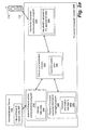
- Figure 2a illustrates a conceptual diagram of a global synchronization system comprising three applications that each store personal information.
- Figure 2b illustrates a conceptual diagram of a distributed synchronization system comprising three applications that each store personal information.
- Figure 3 illustrates a conceptual diagram of a system with two databases that need to be synchronized.
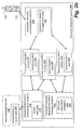
- Figure 4a illustrates a conceptual diagram of a system with three databases being synchronized using the global synchronization system.
- Figure 4b illustrates a conceptual diagram of a system with three databases being synchronized using the distributed synchronization system.
- Figure 1 illustrates a personal computer system 144 coupled to a local area network 140.
- the user of the personal computer system 144 may use a particular personal information management (PIM) program that is provided by his Information Services (IS) department.
- PIM personal information management
- the personal information management (PIM) program stores information such as telephone number & address lists, to-do lists, and a personal daily planner.
- IPM Information Services
- the user may also use other personal information management systems.
- handheld computer system 110 that contains application programs for storing and displaying personal information.
- Examples of handheld computer system 110 may include, but not be limited to, a mobile phone, a personal digital assistant (PDA), or a portable general purpose computer.
- PDA personal digital assistant
- a user may enter personal information into the handheld computer system 110 using a keypad 118.
- the handheld computer system 110 displays personal information on a flat panel display 116.
- the handheld computer system 110 is a cellular telephone that includes an antenna 116 and communications electronics that allow the user to communicate voice and data across a wireless network.
- the handheld computer system 110 may synchronize with a personal information management program on the personal computer system 144.
- the personal information management program on the personal computer system 144 may or may not be the personal information management program provided to the user by his Information Services (IS) department.
- IS Information Services
- Another method of providing access to the user's personal information is to provide the user's personal information on to a personal inventory management program on an Internet or Intranet server 130.
- the Internet/Intranet server 130 in the example of Figure 1 is coupled to both the internal LAN 140 and the global Internet 100.
- any client system coupled to the internal LAN 140 or the global Internet 100 may access the user's personal information, such as stations 106, 102 and 142.
- the personal inventory management program on the Internet/lntranet server 130 should require authentication.
- the personal inventory management program on the Internet/lntranet server 130 provides the benefit of allowing the user to selectively share his personal information with other people that are on the internal LAN 140 or the global Internet 100.
- Figure 2a illustrates a conceptual diagram of three applications in a personal computer 200 that each store personal information: a personal computer information management program 230, an Internet/lntranet server communication program 210, and a handheld computer communication program 220.
- the personal computer information management program 230 may be one of several personal information management programs such as Eudora Planner from Qualcomm, Organizer from Lotus, or Outlook Express from Microsoft.
- the personal computer information management program 230 maintains its own personal information database 235 for the personal computer 200.
- the Internet/Intranet server communication program 210 may be one of several programs that store information on an Internet/lntranet server 130. For example Lotus Notes stores information on a Lotus Domino Server. Similarly, a synchronization program is provided by PlanetAll that stores personal information on a PlanetAll hosted Internet server. (See http://www.PlanetAll.com).
- the Internet/Intranet server communication program 210 may maintain its own personal information database 215 for Internet/lntranet server 130. Alternatively, the Internet/Intranet server communication program 210 may require data in a special input format or use an existing personal computer PIM program that is not the same as the personal computer information management program 230.
- the handheld computer communication program 220 may be one of several programs that communicate with an external handheld computer system 110. Examples of communication programs for handheld computer systems include the Pilot Desktop from 3Com and Intellisync from Puma Technologies.
- the handheld computer communication program 220 may maintain its own personal information database 225 for the external handheld computer system 110.
- a user may have three or more personal information databases that are being used. It would be desirable to keep the contents of all the personal information databases synchronized.
- the present invention provides a system for keeping several different personal information databases synchronized. Two different embodiments are disclosed, although other variations exist.
- the present invention introduces a global synchronization module 250 that periodically accesses the different personal information databases 210, 220 and 230 and synchronizes them.
- the global synchronization module 250 maintains its own synchronization database 255.
- the synchronization database 255 contains information about the various records stored within each database. Specifically, the synchronization database 255 notes when various records are copied or moved from one database to another. To prevent problems introduced by mismatched clocks on different computer systems, global synchronization modules 250 that use clock signals only use clock signals from the clock of the host system.
- the synchronization database 255 stores an entry for each record in each personal information database. Specifically, each entry contains a time stamp for the time that the record was modified in that particular database. Furthermore, the synchronization database 255 contains (1) a time that each database last sent records to each other database; and (2) a time that each database last received records from each other database.
- the synchronization database 255 may assign a unique record identifier to each unique database record. In one embodiment, corresponding records in different database may be assigned the same unique record identifier since the records are (or should be) the same in each database.
- Figure 2b illustrates an alternate embodiment wherein different synchronization modules are used to synchronize different database pairs. Specifically, three different synchronization modules are illustrated.
- a first synchronization module 251 manages data synchronization between the database 215 for the Internet/Intranet server communication program 210 and the database 225 for the handheld computer communication program 220.
- a second synchronization module 252 manages data synchronization between the database 215 for the Internet/Intranet server communication program 210 and the database 235 for the personal computer personal information management program 230.
- the third synchronization module 253 manages data synchronization between the database 225 for the handheld computer communication program 220 and the database 235 for the personal computer personal information management program 230.
- each synchronization module 251, 252, and 253 maintains its own synchronization data 256, 257, and 259, respectively.
- the horizontal axis of Table 1 describes the contents of the synchronization database 355 used to control the synchronization of PIM A Database 315 in PIM program A 310 and PIM B Database 325 in PIM program A 320 illustrated in Figure 3.
- the vertical axis i.e. n-th row is used to describe the changes in the synchronization database 355 as records are changed and databases are synchronized.
- the first column of Table 1 stores the time that a first record, Record X1, was modified in database A.
- the second column of Table 1 stores the time that a second record, Record Y1, was modified in database A.
- the next two columns of Table 1 describe respectively when Database A 315 received records from and sent records to Database B 325. Specifically, the third column specifies when Database A 315 last received records from Database B 325 and the fourth column specifies when Database A 315 last sent records to Database B 325.
- the fifth column of Table 1 stores the time that a corresponding first record, Record X2, was modified in database B.
- the sixth column of Table 1 stores the time that a corresponding second record, Record Y2, was modified in database B 325. Note that these values may be null or even not exist yet if the database have never been synchronized as illustrated in Table 1.
- the seventh column specifies when Database B 325 last received records from Database A 315 and the fourth column specifies when Database B 325 last sent records to Database A 315.
- the synchronization database 355 is empty, i.e. no data or records have been entered. Then, at 1:00 p.m., a user adds Record X1 to database A 315 as noted in the third row of Table 1. Next, the user adds Record Y2 to database B 325 at 1:01 p.m. as specified in the fourth row of Table 1. At this point each database contains one record. The two created records are not synchronized and thus can not be fully accessed from either one of the databases.
- a synchronization is initiated and begins by having database A 315 send records to database B 325. (Later, database B 325 will send records to database A 315.)
- the synchronization database 355 notes that database B 325 begins receiving records from database A 315 at 1:02 p.m., as reflected in fifth row of Table 1.
- Each record in database A 315 is examined and will be sent to database B 325 only if two conditions are satisfied: (1) the record modified time in database A must be greater than the last time that records were sent to database B; and (2) the record modified time in database A must be less than the last time this database received records from database B.
- the record modified time in database A must be greater than the last time that records were sent to database B so that only modified records are being sent.
- the record modified time in database A must be less than the last time this database received records from database B in order to prevent records that were just received from database B from being retransmitted back to the database B. Since X1 has never been sent to database B 325, the modified time is greater than the last sent time. To simplify an implementation, newly created records can be given the oldest possible time that may be set with the field. Thus record X1 is created as record X2 in database B 325 and the last modified time is set to 1:03 p.m. in the sixth row of Table 1.
- database A 315 is done sending records.
- the synchronization module 350 notes the end of sending records from database A 315 to database B 325 in the synchronization database 355. Specifically, the seventh row of Table 1 notes 1:04 p.m. as the finishing time of sending records to database B 325.
- Database B 325 then begins sending records to database A 315.
- the synchronization module 350 notes the beginning of receiving records into database A 315 from database B 325 in the synchronization database 355. Specifically, the eighth row of Table 1 notes 1:05 p.m. as the time database A 315 begins receiving records from database B 325.
- the synchronization module 350 then proceeds to send records from database B 325 to database A 315.
- records are only sent if the record modified time in database B is greater than the last time that records were sent to database A and the record modified time in database B must be less than the last time this database received records from database A.
- the synchronization module 350 When the synchronization module 350 examines record Y2 in database B 325, the synchronization module 350 will sent record Y2 to Database A since record Y2 was modified after records were last sent to database A 315 (1:01 p.m. is greater than never) and record Y2 was modified before the last time records were received from database A (1 :01 p.m. is less than 1:02 p.m.). Thus, a new corresponding record Y1 is created in database A 315. The new Y1 record is given the current time as the modified time. In this example, 1:06 p.m. is assigned as the modified time in the ninth row of Table 1.
- the synchronization module 350 When the synchronization module 350 examines record X2 in database B 325, the synchronization module 350 will not sent record X2 to Database A 315. Record X2 is not sent to database A 315 since the record fails the second part of the test. Specifically, record X2 was not modified before the last time records were received from database A 315 (1:03 p.m. is not less than 1:02 p.m.). Thus, record X2 is not sent to database A 315. This makes sense since database B 325 just received record X2 from database A 315 and has not modified it.
- database B 325 is done sending records to database A 315.
- the synchronization module 350 notes the end of sending records from database A 315 to database B 325 in the synchronization database 355. Specifically, the tenth row of Table 1 notes 1:07 p.m. as the finishing time of sending records to database B 325.
- Clocks in various different computer systems are usually not precisely synchronized.
- the clocks may be completely out of phase.
- Database A Database B Record X1 modified Record Y1 modified In From B Out To B Record X2 modified Record Y2 modified In From A Out To A 1:00 PM 1:00 PM 2:01 PM 1:00 PM 2:01 PM 2:02 PM 1:00 PM 2:03 PM 2:01 PM 2:02 PM 1:00 PM 1:04 PM 2:03 PM 2:01 PM 2:02 PM 1:00 PM 1:05 PM 1:04 PM 2:03 PM 2:01 PM 2:02 PM 1:00 PM 1:06 PM 1:05 PM 1:04 PM 2:03 PM 2:01 PM 2:02 PM 1:00 PM 1:06 PM 1:05 PM 1:04 PM 2:03 PM 2:01 PM 2:02 PM 1:00 PM 1:06 PM 1:05 PM 1:04 PM 2:03 PM 2:01 PM 2:02 PM 1:00 PM 1:06 PM 1:05 PM 1:04 PM 2:03 PM 2:01 PM 2:02 PM 1:00
- actual times may be used when database records are modified, sent, and received.
- the absolute times are not important.
- the system of the present invention could instead be implemented with a version counter that changes after each step that is performed.
- the times could be replaced with an incrementing counter value (100, 101, 102, 103, etc)
- the synchronization module 350 may not be able to obtain the exact time when a particular record has changed from a database. In fact, the synchronization module 350 may not be informed when a record changes. Instead, the synchronization module 350 may store a copy of each database after a synchronization. Then, when a synchronization is initiated, the synchronization module 350 first compares the stored database with the changed database to determine which records have been modified. The current time or an incremented counter will be stored into the modified records' modified time field in the synchronization database 355.
- the synchronization system of the present invention can be extended to multiple database.
- Table 3 illustrates an example of a multiple database synchronization. To simplify the example, only a single database record will be considered.
- Database A Database B Database C Rec Xa mod In from B Out to B In from C Out to C Rec Xb mod In from A Out to A In from C Out to C Rec Xc mod In from A Out to A In from B Out to B 1:00 1:00 1:01 1:00 1:02 1:01 1:00 1:03 1:02 1:01 1:00 1:04 1:03 1:02 1:01 1:00 1:04 1:03 1:02 1:01 1:05 1:00 1:04 1:03 1:02 1:01 1:05 1:00 1:04 1:03 1:02 1:01 1:05 1:06 1:00 1:04 1:03 1:02 1:01 1:05 1:06 1:00 1:04 1:03 1:02 1:01 1:05 1:06 1:00 1:04 1:03 1:02 1:
- the horizontal axis of Table 3 describes the contents of the synchronization database 455 used to control the synchronization of PIM A Database 415 in PIM program A 410 and PIM B Database 425 in PIM program A 420 illustrated in Figure 4a.
- the vertical axis is used to describe the changes in the synchronization database 455 as one record is entered and then the databases are synchronized.
- synchronization database of Table 3 would be split into three different databases, one for each synchronization module. Specifically, synchronization data 456 would contain the data transactions from A to B and B to A, synchronization data 457 would contain the data transactions from A to C and C to A, and synchronization data 459 would contain the data transactions from C to B and B to C.
- the first five columns of Table 3 (synchronization data 455) store a Record Xa in database A, the time when Database A 415 last received records from Database B 425, the last time when Database A 415 last sent records to Database B 425, the time when Database A 415 last received records from Database C 435, and the last time when Database A 415 last sent records to Database C 435.
- the middle five columns of Table 3 store a Record Xb in database B 425, the time when Database B 425 last received records from Database A 415, the last time when Database B 425 last sent records to Database A 415, the time when Database B 425 last received records from Database C 435, and the last time when Database B 425 last sent records to Database C 435.
- the last five columns of Table 3 store a Record Xc in database C 435, the time when Database C 435 last received records from Database A 415, the last time when Database C 435 last sent records to Database A 415, the time when Database C 435 last received records from Database B 425, and the last time when Database C 435 last sent records to Database B 425.
- the vertical axis of the Table 3 sets forth a three-database synchronization example.
- the synchronization database 355 is empty, namely no data or records are entered. Then, at 1:00 p.m., a user adds Record Xa to database A 415 as rioted in the third row of Table 3.
- a synchronization is initiated between databases A and B.
- the synchronization may be user initiated or automatically initiated.
- the synchronization begins by having database A 415 send records to database B 425.
- the synchronization database 455 notes that database B 425 begins receiving records from database A 415 at 1:01 p.m., as reflected in fourth row of Table 3.
- Each record in database A 415 is examined and will be sent to database B 425 only if two conditions are satisfied: (1) the record modified time in database A must be greater that the last time that records were sent to database B; and (2) the record modified time in database A must be less than the last time this database received records from database B. Since Xa has never been sent to database B 425, the modified time is greater than the last sent time (never). Thus record Xa is created in database B 425 as record Xb and the last modified time is set to 1:02 p.m. in the fifth row of Table 3.
- database A 415 is done sending records.
- the synchronization module 450 notes the end of sending records from database A 415 to database B 425 in the synchronization database 455. Specifically, the sixth row of Table 3 notes 1:03 p.m. as the finishing time of sending records to database B 425.
- Database B 425 then begins sending records to database A 415.
- the synchronization module 450 notes the beginning of receiving records into database A 415 from database B 425 in the synchronization database 455. Specifically, the seventh row of Table 1 notes 1:04 p.m. as the time database A 415 begins receiving records from database B 425.
- the synchronization module 450 then proceeds to send records from database B 425 to database A 415. As before, records are only sent if the record modified time in database B is greater that the last time that records were sent to database A and the record modified time in database B is less than the last time this database received records from database A 415.
- the synchronization module 450 notes the end of sending records to database A from database B at 1:05 p.m. as designated in the eighth row of Table 3.
- a synchronization is initiated between databases B and C.
- the synchronization may be user initiated or automatically initiated.
- the synchronization begins by having database B 425 send records to database C 435.
- the synchronization module 450 notes that database C 435 begins receiving records from database B 425 at 1:06 p.m., as reflected in ninth row of Table 3.
- Each record in database B 425 is examined and will be sent to database C 435 only if two conditions are satisfied: (1) the record modified time in database B must be greater that the last time that records were sent to database C; and (2) the record modified time in database B must be less than the last time this database received records from database C.
- the synchronization module 450 After the synchronization module 450 has finished sending records from database B to database C, the synchronization module 450 begins to send records from database C to database B. In the twelfth row of Table3, the synchronization module 450 notes the beginning of database B receiving records from database C at 1:09 p.m. Since no records need to be sent (Record Xc was created after receiving from database B), the synchronization module 450 notes 1:10 p.m. as the time when done sending records from database C to database B in the thirteenth row of Table 3.
- a synchronization is initiated between databases A and C.
- the synchronization begins by having database C 435send records to database A 415.
- the synchronization module 450 notes that database A 415 begins receiving records from database C 435 at 1:11 p.m., as reflected in fourteenth row of Table 3.
- Each record in database C 435 is examined and will be sent to database A 415 only if two conditions are satisfied: (1) the record modified time in database C must be greater that the last time that records were sent to database A; and (2) the record modified time in database C must be less than the last time this database received records from database A. Since Xc in database C 435 has never been sent to database A 415, the modified time is greater than the last sent time (never).
- record Xc is send to database A 415.
- database A 415 compares the received record with existing records to determine if the received record is a duplicate record.
- database A 415 compares the newly received record (record Xc) with the existing record Xa, database A 415 will determine that the records are exact duplicates. Thus, database A 415 will discard the newly received record since it already has that record.
- the synchronization module 450 notes the end time of sending records to database A from database C at 1:12 p.m. in the fifteenth row of Table 3. The synchronization module 450 then begins to send records from database A to database C. In the sixteenth row of Table 3, the synchronization module 450 notes the beginning of database C receiving records from database A at 1:13 p.m.
- the synchronization module 450 examines record Xc, the synchronization module 450 will attempt to send the record as it was modified since database A last sent records to database C (never) and Xa was modified before receiving records from database C. However, when database C receives the record, database C will discard the record since record Xa exactly matches the existing Xc message. Finally, the synchronization module 450 notes the end of sending messages from database A to database C at 1:14 in the seventeenth row of Table 3.
- a double modify situation occurs when the synchronization module detects that a record has been either added or modified in both databases. For example, consider the following case:
Abstract
Description
- The present invention relates to the field of database coherency in computer systems. In particular the present invention discloses a synchronization system that keeps a plurality of different database synchronized.
- More and more people are relying upon computer devices to organize their lives. For example, many people use computer systems to maintain personal information such as telephone number & address lists, to-do lists, and a personal daily planner. Many people store this personal information on personal information management application programs on desktop personal computers. However, when such people are away from their personal computers this valuable personal information is not available since it is stored in the desktop personal computer system.
- One method of making this personal information available at other locations is to put the personal information onto a server coupled to the Internet. To protect the personal information, the server may require that a user authenticate himself before the server provides access to the personal information. One Internet web site is currently offering personal information storage on the Internet as a free service. (See http://www.planetall.com/) However, to access personal information stored on an Internet server, a person must still have access to the Internet.
- Another method of making personal information accessible is to place the personal information on a handheld computer system. To provide this functionality, a new class of portable handheld computer systems has emerged. For example, the 3Com PalmPilot, the 3Com Palm III, and Windows CE based Palm-sized personal computers all provide applications for storing personal information.
- When a person uses more than one of these personal information storage systems (personal computer applications, Internet servers, handheld computer systems, etc.), the person needs to keep the personal information storage systems synchronized such that the same data is available in all the different storage systems. Some systems have addressed having two personal information systems synchronized. For example, the 3Com PalmPilot synchronizes a personal computer based personal information management program with a PalmPilot handheld computer system. However, it would be desirable to have more than just two personal information storage systems synchronized such that a person could use a plurality of personal information systems concurrently.
- A database synchronization system is disclosed. In the database synchronization system, a synchronization database is created. The synchronization database stores a relative sent time that specifies when each database last attempted to send records to each other database, a relative receive time that specifies when each database last attempted to received records from each other database, and a relative record modified time that specifies when each record in each database was last created or modified.
- The synchronization system operates by comparing each record modified time to the relative sent time and the relative receive time. Records are only sent from a first database to a second database if the relative record modified time for that record designates a later time than the relative sent time that specifies when the first database last sent records to the second database and the relative record modified time specifies an earlier time than the relative receive time that specifies the time the first database last received records from the second database.
- Other objects, features, and advantages of present invention will be apparent from the company drawings and from the following detailed description.
- The objects, features and advantages of the present invention will be apparent to one skilled in the art, in view of the following detailed description in which:
- Figure 1 illustrates a systemic configuration in which the present invention can be practised.
- Figure 2a illustrates a conceptual diagram of a global synchronization system comprising three applications that each store personal information.
- Figure 2b illustrates a conceptual diagram of a distributed synchronization system comprising three applications that each store personal information.
- Figure 3 illustrates a conceptual diagram of a system with two databases that need to be synchronized.
- Figure 4a illustrates a conceptual diagram of a system with three databases being synchronized using the global synchronization system.
- Figure 4b illustrates a conceptual diagram of a system with three databases being synchronized using the distributed synchronization system.
- A system for synchronizing information in multiple databases is disclosed. In the following description, for purposes of explanation, specific nomenclature is set forth to provide a thorough understanding of the present invention. However, it will be apparent to one skilled in the art that these specific details are not required in order to practice the present invention. For example, the present invention has been described with reference to personal information such as names, addresses and telephone numbers. However, the same techniques can easily be applied to any other type of information stored in databases.
- Figure 1 illustrates a
personal computer system 144 coupled to alocal area network 140. The user of thepersonal computer system 144 may use a particular personal information management (PIM) program that is provided by his Information Services (IS) department. The personal information management (PIM) program stores information such as telephone number & address lists, to-do lists, and a personal daily planner. However, to provide greater access the personal information, the user may also use other personal information management systems. - One commonly used personal information management system is
handheld computer system 110 that contains application programs for storing and displaying personal information. Examples ofhandheld computer system 110 may include, but not be limited to, a mobile phone, a personal digital assistant (PDA), or a portable general purpose computer. A user may enter personal information into thehandheld computer system 110 using akeypad 118. Thehandheld computer system 110 displays personal information on aflat panel display 116. In one embodiment, thehandheld computer system 110 is a cellular telephone that includes anantenna 116 and communications electronics that allow the user to communicate voice and data across a wireless network. - To keep the personal information in the
handheld computer system 110 current, thehandheld computer system 110 may synchronize with a personal information management program on thepersonal computer system 144. The personal information management program on thepersonal computer system 144 may or may not be the personal information management program provided to the user by his Information Services (IS) department. - Another method of providing access to the user's personal information is to provide the user's personal information on to a personal inventory management program on an Internet or Intranet
server 130. The Internet/Intranet server 130 in the example of Figure 1 is coupled to both theinternal LAN 140 and theglobal Internet 100. Thus, any client system coupled to theinternal LAN 140 or theglobal Internet 100 may access the user's personal information, such asstations lntranet server 130 should require authentication. The personal inventory management program on the Internet/lntranet server 130 provides the benefit of allowing the user to selectively share his personal information with other people that are on theinternal LAN 140 or theglobal Internet 100. - An active user may wish to use all three personal information management systems previously described. Figure 2a illustrates a conceptual diagram of three applications in a
personal computer 200 that each store personal information: a personal computerinformation management program 230, an Internet/lntranetserver communication program 210, and a handheldcomputer communication program 220. - The personal computer
information management program 230 may be one of several personal information management programs such as Eudora Planner from Qualcomm, Organizer from Lotus, or Outlook Express from Microsoft. The personal computerinformation management program 230 maintains its ownpersonal information database 235 for thepersonal computer 200. - The Internet/Intranet
server communication program 210 may be one of several programs that store information on an Internet/lntranet server 130. For example Lotus Notes stores information on a Lotus Domino Server. Similarly, a synchronization program is provided by PlanetAll that stores personal information on a PlanetAll hosted Internet server. (See http://www.PlanetAll.com). The Internet/Intranetserver communication program 210 may maintain its ownpersonal information database 215 for Internet/lntranet server 130. Alternatively, the Internet/Intranetserver communication program 210 may require data in a special input format or use an existing personal computer PIM program that is not the same as the personal computerinformation management program 230. - The handheld
computer communication program 220 may be one of several programs that communicate with an externalhandheld computer system 110. Examples of communication programs for handheld computer systems include the Pilot Desktop from 3Com and Intellisync from Puma Technologies. The handheldcomputer communication program 220 may maintain its ownpersonal information database 225 for the externalhandheld computer system 110. - Thus, as illustrated in the example of Figure 2a, a user may have three or more personal information databases that are being used. It would be desirable to keep the contents of all the personal information databases synchronized.
- The present invention provides a system for keeping several different personal information databases synchronized. Two different embodiments are disclosed, although other variations exist.
- Referring to Figure 2a, the present invention introduces a
global synchronization module 250 that periodically accesses the differentpersonal information databases - The
global synchronization module 250 maintains itsown synchronization database 255. Thesynchronization database 255 contains information about the various records stored within each database. Specifically, thesynchronization database 255 notes when various records are copied or moved from one database to another. To prevent problems introduced by mismatched clocks on different computer systems,global synchronization modules 250 that use clock signals only use clock signals from the clock of the host system. - The
synchronization database 255 stores an entry for each record in each personal information database. Specifically, each entry contains a time stamp for the time that the record was modified in that particular database. Furthermore, thesynchronization database 255 contains (1) a time that each database last sent records to each other database; and (2) a time that each database last received records from each other database. - The
synchronization database 255 may assign a unique record identifier to each unique database record. In one embodiment, corresponding records in different database may be assigned the same unique record identifier since the records are (or should be) the same in each database. - Figure 2b illustrates an alternate embodiment wherein different synchronization modules are used to synchronize different database pairs. Specifically, three different synchronization modules are illustrated. A
first synchronization module 251 manages data synchronization between thedatabase 215 for the Internet/Intranetserver communication program 210 and thedatabase 225 for the handheldcomputer communication program 220. Asecond synchronization module 252 manages data synchronization between thedatabase 215 for the Internet/Intranetserver communication program 210 and thedatabase 235 for the personal computer personalinformation management program 230. Thethird synchronization module 253 manages data synchronization between thedatabase 225 for the handheldcomputer communication program 220 and thedatabase 235 for the personal computer personalinformation management program 230. In such an embodiment, eachsynchronization module own synchronization data - To describe a simple example of the operation of the multiple database system using the global synchronization system as illustrate in Figure 2a, a two-database example is provided with reference to the following table and Figure 3.
Database A Database B Record X1 modified Record Y1 modified In From B Out To B Record X2 modified Record Y2 modified In From A Out To A 1:00 PM 1:00 PM 1:01 PM 1:00 PM 1:01 PM 1:02 PM 1:00 PM 1:03 PM 1:01 PM 1:02 PM 1:00 PM 1:04 PM 1:03 PM 1:01 PM 1:02 PM 1:00 PM 1:05 PM 1:04 PM 1:03 PM 1:01 PM 1:02 PM 1:00 PM 1:06 PM 1:05 PM 1:04 PM 1:03 PM 1:01 PM 1:02 PM 1:00 PM 1:06 PM 1:05 PM 1:04 PM 1:03 PM 1:01 PM 1:02 PM 1:07 PM - The horizontal axis of Table 1 describes the contents of the
synchronization database 355 used to control the synchronization ofPIM A Database 315 inPIM program A 310 andPIM B Database 325 inPIM program A 320 illustrated in Figure 3. The vertical axis (i.e. n-th row) is used to describe the changes in thesynchronization database 355 as records are changed and databases are synchronized. - The first column of Table 1 stores the time that a first record, Record X1, was modified in database A. The second column of Table 1 stores the time that a second record, Record Y1, was modified in database A. The next two columns of Table 1 describe respectively when
Database A 315 received records from and sent records toDatabase B 325. Specifically, the third column specifies whenDatabase A 315 last received records fromDatabase B 325 and the fourth column specifies whenDatabase A 315 last sent records toDatabase B 325. - The fifth column of Table 1 stores the time that a corresponding first record, Record X2, was modified in database B. The sixth column of Table 1 stores the time that a corresponding second record, Record Y2, was modified in
database B 325. Note that these values may be null or even not exist yet if the database have never been synchronized as illustrated in Table 1. The seventh column specifies whenDatabase B 325 last received records fromDatabase A 315 and the fourth column specifies whenDatabase B 325 last sent records toDatabase A 315. - Referring to the second row of Table 1, the
synchronization database 355 is empty, i.e. no data or records have been entered. Then, at 1:00 p.m., a user adds Record X1 todatabase A 315 as noted in the third row of Table 1. Next, the user adds Record Y2 todatabase B 325 at 1:01 p.m. as specified in the fourth row of Table 1. At this point each database contains one record. The two created records are not synchronized and thus can not be fully accessed from either one of the databases. - A synchronization is initiated and begins by having
database A 315 send records todatabase B 325. (Later,database B 325 will send records todatabase A 315.) Thesynchronization database 355 notes thatdatabase B 325 begins receiving records fromdatabase A 315 at 1:02 p.m., as reflected in fifth row of Table 1. Each record indatabase A 315 is examined and will be sent todatabase B 325 only if two conditions are satisfied: (1) the record modified time in database A must be greater than the last time that records were sent to database B; and (2) the record modified time in database A must be less than the last time this database received records from database B. The record modified time in database A must be greater than the last time that records were sent to database B so that only modified records are being sent. The record modified time in database A must be less than the last time this database received records from database B in order to prevent records that were just received from database B from being retransmitted back to the database B. Since X1 has never been sent todatabase B 325, the modified time is greater than the last sent time. To simplify an implementation, newly created records can be given the oldest possible time that may be set with the field. Thus record X1 is created as record X2 indatabase B 325 and the last modified time is set to 1:03 p.m. in the sixth row of Table 1. - Since X1 was the only record in
database A 315,database A 315 is done sending records. Thesynchronization module 350 notes the end of sending records fromdatabase A 315 todatabase B 325 in thesynchronization database 355. Specifically, the seventh row of Table 1 notes 1:04 p.m. as the finishing time of sending records todatabase B 325. -
Database B 325 then begins sending records todatabase A 315. Thesynchronization module 350 notes the beginning of receiving records intodatabase A 315 fromdatabase B 325 in thesynchronization database 355. Specifically, the eighth row of Table 1 notes 1:05 p.m. as thetime database A 315 begins receiving records fromdatabase B 325. - The
synchronization module 350 then proceeds to send records fromdatabase B 325 todatabase A 315. As before, records are only sent if the record modified time in database B is greater than the last time that records were sent to database A and the record modified time in database B must be less than the last time this database received records from database A. - When the
synchronization module 350 examines record Y2 indatabase B 325, thesynchronization module 350 will sent record Y2 to Database A since record Y2 was modified after records were last sent to database A 315 (1:01 p.m. is greater than never) and record Y2 was modified before the last time records were received from database A (1 :01 p.m. is less than 1:02 p.m.). Thus, a new corresponding record Y1 is created indatabase A 315. The new Y1 record is given the current time as the modified time. In this example, 1:06 p.m. is assigned as the modified time in the ninth row of Table 1. - When the
synchronization module 350 examines record X2 indatabase B 325, thesynchronization module 350 will not sent record X2 toDatabase A 315. Record X2 is not sent todatabase A 315 since the record fails the second part of the test. Specifically, record X2 was not modified before the last time records were received from database A 315 (1:03 p.m. is not less than 1:02 p.m.). Thus, record X2 is not sent todatabase A 315. This makes sense sincedatabase B 325 just received record X2 fromdatabase A 315 and has not modified it. - Finally, since X2 and Y2 were the only record in
database B 325,database B 325 is done sending records todatabase A 315. Thesynchronization module 350 notes the end of sending records fromdatabase A 315 todatabase B 325 in thesynchronization database 355. Specifically, the tenth row of Table 1 notes 1:07 p.m. as the finishing time of sending records todatabase B 325. - Clocks in various different computer systems are usually not precisely synchronized. For example, referring to Table 2 below, the clocks may be completely out of phase.
Database A Database B Record X1 modified Record Y1 modified In From B Out To B Record X2 modified Record Y2 modified In From A Out To A 1:00 PM 1:00 PM 2:01 PM 1:00 PM 2:01 PM 2:02 PM 1:00 PM 2:03 PM 2:01 PM 2:02 PM 1:00 PM 1:04 PM 2:03 PM 2:01 PM 2:02 PM 1:00 PM 1:05 PM 1:04 PM 2:03 PM 2:01 PM 2:02 PM 1:00 PM 1:06 PM 1:05 PM 1:04 PM 2:03 PM 2:01 PM 2:02 PM 1:00 PM 1:06 PM 1:05 PM 1:04 PM 2:03 PM 2:01 PM 2:02 PM 2:07 PM - As set forth in the previous examples, actual times may be used when database records are modified, sent, and received. However, the absolute times are not important. Thus, the system of the present invention could instead be implemented with a version counter that changes after each step that is performed. For example, referring to the previous examples, the times could be replaced with an incrementing counter value (100, 101, 102, 103, etc)
- Thus, the exact time when a record changes is not necessary. The important fact to know is if a record has changed before or after a particular synchronization. Referring to Figure 3, the
synchronization module 350 may not be able to obtain the exact time when a particular record has changed from a database. In fact, thesynchronization module 350 may not be informed when a record changes. Instead, thesynchronization module 350 may store a copy of each database after a synchronization. Then, when a synchronization is initiated, thesynchronization module 350 first compares the stored database with the changed database to determine which records have been modified. The current time or an incremented counter will be stored into the modified records' modified time field in thesynchronization database 355. - The synchronization system of the present invention can be extended to multiple database. The following table, Table 3, illustrates an example of a multiple database synchronization. To simplify the example, only a single database record will be considered.
Database A Database B Database C Rec Xa mod In from B Out to B In from C Out to C Rec Xb mod In from A Out to A In from C Out to C Rec Xc mod In from A Out to A In from B Out to B 1:00 1:00 1:01 1:00 1:02 1:01 1:00 1:03 1:02 1:01 1:00 1:04 1:03 1:02 1:01 1:00 1:04 1:03 1:02 1:01 1:05 1:00 1:04 1:03 1:02 1:01 1:05 1:06 1:00 1:04 1:03 1:02 1:01 1:05 1:07 1:06 1:00 1:04 1:03 1:02 1:01 1:05 1:08 1:07 1:06 1:00 1:04 1:03 1:02 1:01 1:05 1:09 1:08 1:07 1:06 1:00 1:04 1:03 1:02 1:01 1:05 1:09 1:08 1:07 1:06 1:10 1:00 1:04 1:03 1:11 1:02 1:01 1:05 1:09 1:08 1:07 1:06 1:10 1:00 1:04 1:03 1:11 1:02 1:01 1:05 1:09 1:08 1:07 1:12 1:06 1:10 1:00 1:04 1:03 1:11 1:02 1:01 1:05 1:09 1:08 1:07 1:13 1:12 1:06 1:10 1:00 1:04 1:03 1:11 1:14 1:02 1:01 1:05 1:09 1:08 1:07 1:13 1:12 1:06 1:10 - The horizontal axis of Table 3 describes the contents of the
synchronization database 455 used to control the synchronization ofPIM A Database 415 inPIM program A 410 andPIM B Database 425 inPIM program A 420 illustrated in Figure 4a. The vertical axis is used to describe the changes in thesynchronization database 455 as one record is entered and then the databases are synchronized. - In a distributed synchronization module environment, as illustrated in Figure 4b, the synchronization database of Table 3 would be split into three different databases, one for each synchronization module. Specifically,
synchronization data 456 would contain the data transactions from A to B and B to A,synchronization data 457 would contain the data transactions from A to C and C to A, andsynchronization data 459 would contain the data transactions from C to B and B to C. - Referring back to the global synchronization embodiment of Figure 4a, the first five columns of Table 3 (synchronization data 455) store a Record Xa in database A, the time when
Database A 415 last received records fromDatabase B 425, the last time whenDatabase A 415 last sent records toDatabase B 425, the time whenDatabase A 415 last received records fromDatabase C 435, and the last time whenDatabase A 415 last sent records toDatabase C 435. - The middle five columns of Table 3 store a Record Xb in
database B 425, the time whenDatabase B 425 last received records fromDatabase A 415, the last time whenDatabase B 425 last sent records toDatabase A 415, the time whenDatabase B 425 last received records fromDatabase C 435, and the last time whenDatabase B 425 last sent records toDatabase C 435. - The last five columns of Table 3 store a Record Xc in
database C 435, the time whenDatabase C 435 last received records fromDatabase A 415, the last time whenDatabase C 435 last sent records toDatabase A 415, the time whenDatabase C 435 last received records fromDatabase B 425, and the last time whenDatabase C 435 last sent records toDatabase B 425. - The vertical axis of the Table 3 sets forth a three-database synchronization example. Referring to the second row of Table 3, the
synchronization database 355 is empty, namely no data or records are entered. Then, at 1:00 p.m., a user adds Record Xa todatabase A 415 as rioted in the third row of Table 3. - Next, a synchronization is initiated between databases A and B. The synchronization may be user initiated or automatically initiated. The synchronization begins by having
database A 415 send records todatabase B 425. Thesynchronization database 455 notes thatdatabase B 425 begins receiving records fromdatabase A 415 at 1:01 p.m., as reflected in fourth row of Table 3. Each record indatabase A 415 is examined and will be sent todatabase B 425 only if two conditions are satisfied: (1) the record modified time in database A must be greater that the last time that records were sent to database B; and (2) the record modified time in database A must be less than the last time this database received records from database B. Since Xa has never been sent todatabase B 425, the modified time is greater than the last sent time (never). Thus record Xa is created indatabase B 425 as record Xb and the last modified time is set to 1:02 p.m. in the fifth row of Table 3. - Since Xa was the only record in
database A 415,database A 415 is done sending records. Thesynchronization module 450 notes the end of sending records fromdatabase A 415 todatabase B 425 in thesynchronization database 455. Specifically, the sixth row of Table 3 notes 1:03 p.m. as the finishing time of sending records todatabase B 425. -
Database B 425 then begins sending records todatabase A 415. Thesynchronization module 450 notes the beginning of receiving records intodatabase A 415 fromdatabase B 425 in thesynchronization database 455. Specifically, the seventh row of Table 1 notes 1:04 p.m. as thetime database A 415 begins receiving records fromdatabase B 425. Thesynchronization module 450 then proceeds to send records fromdatabase B 425 todatabase A 415. As before, records are only sent if the record modified time in database B is greater that the last time that records were sent to database A and the record modified time in database B is less than the last time this database received records fromdatabase A 415. However, since the only record indatabase B 425 is record Xb that was created after records were received fromdatabase A 415, no records will be sent fromdatabase B 425. Thus, thesynchronization module 450 notes the end of sending records to database A from database B at 1:05 p.m. as designated in the eighth row of Table 3. - Next, a synchronization is initiated between databases B and C. Again, the synchronization may be user initiated or automatically initiated. The synchronization begins by having
database B 425 send records todatabase C 435. Thesynchronization module 450 notes thatdatabase C 435 begins receiving records fromdatabase B 425 at 1:06 p.m., as reflected in ninth row of Table 3. Each record indatabase B 425 is examined and will be sent todatabase C 435 only if two conditions are satisfied: (1) the record modified time in database B must be greater that the last time that records were sent to database C; and (2) the record modified time in database B must be less than the last time this database received records from database C. Since Xb indatabase B 425 has never been sent todatabase C 435, the modified time is greater than the last sent time (never). Thus record Xb is created indatabase C 435 as record Xc and the last modified time is set to 1:07 p.m. in the tenth row of Table 3. Since record Xb is the only record indatabase B 425, thesynchronization module 450 notes the end time of sending records to database C from database B at 1:08 p.m. in the eleventh row of Table 3. - After the
synchronization module 450 has finished sending records from database B to database C, thesynchronization module 450 begins to send records from database C to database B. In the twelfth row of Table3, thesynchronization module 450 notes the beginning of database B receiving records from database C at 1:09 p.m. Since no records need to be sent (Record Xc was created after receiving from database B), thesynchronization module 450 notes 1:10 p.m. as the time when done sending records from database C to database B in the thirteenth row of Table 3. - Next, a synchronization is initiated between databases A and C. The synchronization begins by having database C 435send records to
database A 415. Thesynchronization module 450 notes thatdatabase A 415 begins receiving records fromdatabase C 435 at 1:11 p.m., as reflected in fourteenth row of Table 3. Each record indatabase C 435 is examined and will be sent todatabase A 415 only if two conditions are satisfied: (1) the record modified time in database C must be greater that the last time that records were sent to database A; and (2) the record modified time in database C must be less than the last time this database received records from database A. Since Xc indatabase C 435 has never been sent todatabase A 415, the modified time is greater than the last sent time (never). Thus record Xc is send todatabase A 415. However,database A 415 compares the received record with existing records to determine if the received record is a duplicate record. Whendatabase A 415 compares the newly received record (record Xc) with the existing record Xa,database A 415 will determine that the records are exact duplicates. Thus,database A 415 will discard the newly received record since it already has that record. - Since record Xc is the only record in
database C 435, thesynchronization module 450 notes the end time of sending records to database A from database C at 1:12 p.m. in the fifteenth row of Table 3. Thesynchronization module 450 then begins to send records from database A to database C. In the sixteenth row of Table 3, thesynchronization module 450 notes the beginning of database C receiving records from database A at 1:13 p.m. When thesynchronization module 450 examines record Xc, thesynchronization module 450 will attempt to send the record as it was modified since database A last sent records to database C (never) and Xa was modified before receiving records from database C. However, when database C receives the record, database C will discard the record since record Xa exactly matches the existing Xc message. Finally, thesynchronization module 450 notes the end of sending messages from database A to database C at 1:14 in the seventeenth row of Table 3. - A double modify situation occurs when the synchronization module detects that a record has been either added or modified in both databases. For example, consider the following case:
- 1. The user adds record Xa to Database A.
- 2. Database A synchronizes with Database B.
- 3. Database A synchronizes with Database C.
- 4. Database B synchronizes with Database C. In the second and third steps of this example, Record Xa is added in both Database B and Database C. Even if the accurate time that each record had been added or modified was known, that may not be the right information to use to decide which record to keep and which to discard. The prior art procedure for handling such situations has been to add both records to both databases, so that you end up with twice as many records. This will be undesirable for the synchronization system of the present invention because in the situation outlined above, all records would be duplicated. To put it more simply, when two databases sync for the first time, if the two databases have each synced with a third database in the past, there will be a lot of record duplication. To handle such cases, exact duplicate records could be deleted and user input could be used to resolve the remainder of such cases. 0 The following steps describe one possible method of handling the situation when a double modify or add is detected:
- 1. Compare the content of the records. If the records are exact duplicates, discard the record, otherwise:
- 2. If any rules have been chosen by the user then use those rules, otherwise:
- 3. Query the user, giving the user the options to:
- a) Specify which database "wins" for this record.
- b) Specify which database "wins" for all records in this synchronization.
- c) Not synchronize this record.
- d) Not synchronize any conflicting records.
- e) Duplicate these records.
- f) Duplicate all conflicting records.
-
- The foregoing has described a system of synchronizing multiple databases. It is contemplated that changes and modifications may be made by one of ordinary skilled in the art, to the materials and arrangements of elements of the present invention without departing from the scope of the invention.
Claims (10)
- A method of synchronizing multiple databases, said method comprising:-storing a first record in a first database;initiating a synchronization between said first database and a second database; andsending said first record to said second database if said first record was created or modified after last sending records from said first database to said second database and said first record was created or modified before last receiving records from said second database into said first database.
- A method as claimed in claim 1 further comprising:-
discarding said first record from said second database if an identical matching record already exists in said first database. - A method as claimed in claim 1 or 2 further comprising:-
sending a second record in said second database to said first database if said second record was created or modified after last sending records from said second database to said first database and said second record was created or modified before last receiving records from said first database into said second database. - A method as claimed in any preceding claim further comprising:-initiating a synchronization between said first database and a third database; andsending said first record to said third database if said first record was created or modified after last sending records from said first database to said third database and said first record was created or modified before last receiving records from said third database into said first database.
- A method as claimed in any one of claims 1 to 3 further comprising:-initiating a synchronization between said second database and a third database; andsending said first record from said second database to said third database if said first record was created or modified after last sending records from said second database to said third database and said first record was created or modified before last receiving records from said third database into said second database.
- A synchronization system for synchronizing records in a first database and a second database, said system comprising:-a synchronization database, said synchronization database comprising:-a relative first database to second database value, said relative first database to second database value storing a first relative time value specifying when a first database last attempted to send records to a second database;a relative first database from second database value, said relative first database from second database value storing a second relative time value specifying when said first database last attempted to receive records from said second database;at least one record modified value, each record modified value corresponding to each record in each database, said record modified value storing a third relative time value that specifies when said corresponding record was created or modified; anda synchronization module; said synchronization module sending a first record from said first database to said second database if a first record modified value corresponding to said first record designates a later time than said relative first database to second database value and said first record modified value designates an earlier time than said relative first database from second database value.
- A synchronization system as claimed in claim 6 wherein said synchronization database further comprises:-a relative second database to first database value, said relative second database to first database value storing a fourth relative time value specifying when a second database last attempted to send records to a first database; anda relative second database from first database value, said relative second database from first database value storing a fifth relative time value specifying when said second database last attempted to receive records from said first database;wherein said synchronization module sends a second record from said second database to said first database if a second record modified value corresponding to said second record designates a later time than said relative second database to first database value and said second record modified value designates an earlier time than said relative second database from first database value.
- A method of synchronizing multiple databases, said method comprising:-initiating a synchronization among said multiple databases, said multiple databases comprising at least two database, a first database and a second database;examining a first record in said first database to determine if said first record was created or modified after a last time said first database sent records to said second database and before a last time said first database received records from said second database; andsending a copy of said first record to said second database when said first record was created or modified after the last time said first database sent records to said second database and before the last time said first database received records from said second database.
- A method as claimed in claim 8 further comprising:-examining a second record in said second database to determine if said second record was created or modified after a last time said second database sent records to said first database and before a last time said second database received records from said first database;sending a copy of said second record to said first database when said second record was created or modified after a last time said second database sent records to said first database and before a last time said second database received records from said first database;recording a third value in said second database to identify that said copy of said second record has been sent to said first database; andrecording a fourth value in said first database to identify that said copy of said second record has been received from said second database.
- A synchronization system for synchronizing multiple databases, said system comprising:-a data storage device for a first database and a second database;a memory for a synchronization module;a processor coupled to said memory and said data storage device, the processor causing said synchronization module to:-examine a first record in said first database to determine if said first record was created or modified after a last time said first database sent records to said second database and before a last time said first database received records from said second database;send a copy of said first record to said second database when said first record was created or modified after the last time said first database sent records to said second database and before the last time said first database received records from said second dataoase;examine a second record in said second database to determine if said second record was created or modified after a last time said second database sent records to said first database and before a last time said second database receive records from said first database; andsend a copy of said second record to said first database when said second record was created or modified after a last time said second database sent records to said first database and before a last time said second database receive records from said first database.
Applications Claiming Priority (2)
| Application Number | Priority Date | Filing Date | Title |
|---|---|---|---|
| US23903999A | 1999-01-27 | 1999-01-27 | |
| US239039 | 1999-01-27 |
Publications (2)
| Publication Number | Publication Date |
|---|---|
| EP1024441A2 true EP1024441A2 (en) | 2000-08-02 |
| EP1024441A3 EP1024441A3 (en) | 2001-03-21 |
Family
ID=22900350
Family Applications (1)
| Application Number | Title | Priority Date | Filing Date |
|---|---|---|---|
| EP00300614A Withdrawn EP1024441A3 (en) | 1999-01-27 | 2000-01-27 | Method and apparatus for synchronizing multiple databases |
Country Status (4)
| Country | Link |
|---|---|
| EP (1) | EP1024441A3 (en) |
| JP (1) | JP2000235513A (en) |
| KR (1) | KR20010006590A (en) |
| CN (1) | CN1262481A (en) |
Cited By (29)
| Publication number | Priority date | Publication date | Assignee | Title |
|---|---|---|---|---|
| WO2002027559A1 (en) * | 2000-09-29 | 2002-04-04 | Palm, Inc. | A system for sharing information |
| WO2002086758A1 (en) | 2001-04-25 | 2002-10-31 | Nokia Corporation | Synchronization of database data |
| EP1271319A1 (en) * | 2001-06-27 | 2003-01-02 | Microsoft Corporation | System and method for resolving conflicts detected during a synchronization session |
| EP1383054A1 (en) * | 2002-07-19 | 2004-01-21 | SCHLUMBERGER Systèmes | Data synchronization procedures for smartcards |
| FR2850814A1 (en) * | 2003-02-03 | 2004-08-06 | France Telecom | SYSTEM AND METHOD FOR SYNCHRONIZING DATA BETWEEN SERVICE PORTALS AND SERVICE ACCESS PLATFORM USING SUCH A SYNCHRONIZATION SYSTEM |
| US6847983B2 (en) | 2001-02-28 | 2005-01-25 | Kiran Somalwar | Application independent write monitoring method for fast backup and synchronization of open files |
| US6985915B2 (en) | 2001-02-28 | 2006-01-10 | Kiran Somalwar | Application independent write monitoring method for fast backup and synchronization of files |
| US7818435B1 (en) | 2000-12-14 | 2010-10-19 | Fusionone, Inc. | Reverse proxy mechanism for retrieving electronic content associated with a local network |
| US7895334B1 (en) | 2000-07-19 | 2011-02-22 | Fusionone, Inc. | Remote access communication architecture apparatus and method |
| US8073954B1 (en) | 2000-07-19 | 2011-12-06 | Synchronoss Technologies, Inc. | Method and apparatus for a secure remote access system |
| US8156074B1 (en) | 2000-01-26 | 2012-04-10 | Synchronoss Technologies, Inc. | Data transfer and synchronization system |
| US8181111B1 (en) | 2007-12-31 | 2012-05-15 | Synchronoss Technologies, Inc. | System and method for providing social context to digital activity |
| US8255006B1 (en) | 2009-11-10 | 2012-08-28 | Fusionone, Inc. | Event dependent notification system and method |
| CN102843395A (en) * | 2011-06-22 | 2012-12-26 | 阿里巴巴集团控股有限公司 | Data synchronization method and device |
| US8442943B2 (en) | 2000-01-26 | 2013-05-14 | Synchronoss Technologies, Inc. | Data transfer and synchronization between mobile systems using change log |
| US20130124467A1 (en) * | 2011-11-14 | 2013-05-16 | Siddartha Naidu | Data Processing Service |
| US8543540B1 (en) | 2012-05-09 | 2013-09-24 | Bertec Corporation | System and method for the merging of databases |
| US8611873B2 (en) | 2004-05-12 | 2013-12-17 | Synchronoss Technologies, Inc. | Advanced contact identification system |
| US8615566B1 (en) | 2001-03-23 | 2013-12-24 | Synchronoss Technologies, Inc. | Apparatus and method for operational support of remote network systems |
| US8620286B2 (en) | 2004-02-27 | 2013-12-31 | Synchronoss Technologies, Inc. | Method and system for promoting and transferring licensed content and applications |
| US8645471B2 (en) | 2003-07-21 | 2014-02-04 | Synchronoss Technologies, Inc. | Device message management system |
| US8655836B2 (en) | 2009-10-23 | 2014-02-18 | Zte Corporation | Method, device and system for implementing data synchronization between source database and target database |
| US8700569B1 (en) | 2012-05-09 | 2014-04-15 | Bertec Corporation | System and method for the merging of databases |
| US8943428B2 (en) | 2010-11-01 | 2015-01-27 | Synchronoss Technologies, Inc. | System for and method of field mapping |
| EP2843879A1 (en) * | 2013-09-03 | 2015-03-04 | HAGER CONTROLS (Société par Actions Simplifiée) | Configuration of a home-automation network |
| CN104537046A (en) * | 2014-12-24 | 2015-04-22 | 北京奇虎科技有限公司 | Method and device for complementing data |
| US9043278B1 (en) | 2012-05-09 | 2015-05-26 | Bertec Corporation | System and method for the merging of databases |
| EP2966580A1 (en) * | 2014-07-10 | 2016-01-13 | Siemens Product Lifecycle Management Software Inc. | Data re-transfer with site based three point merges using import records |
| US9361433B2 (en) | 2012-08-03 | 2016-06-07 | Synchronoss Technologies, Inc | Enterprise leasing license algorithm |
Families Citing this family (14)
| Publication number | Priority date | Publication date | Assignee | Title |
|---|---|---|---|---|
| KR20020048832A (en) * | 2000-12-18 | 2002-06-24 | (주)소프트컴퍼니 | synchronization program for web & local system data |
| CN100361439C (en) * | 2002-07-30 | 2008-01-09 | 上海阿尔卡特网络支援系统有限公司 | Program controlled switcher database corresponding system |
| JP3860098B2 (en) * | 2002-08-30 | 2006-12-20 | 株式会社東芝 | Information terminal equipment |
| CN101311933B (en) * | 2002-09-03 | 2011-12-28 | Sap股份公司 | Method and system for receiving dynamic access data |
| KR20040039863A (en) * | 2002-11-05 | 2004-05-12 | 한국신용평가정보주식회사 | System for working together private information with enterprise information |
| CN100343846C (en) * | 2003-09-28 | 2007-10-17 | 华为技术有限公司 | Analytical comparison method for divergence between data |
| CN1677355B (en) * | 2004-03-31 | 2010-05-26 | 深圳市朗科科技股份有限公司 | Method system and apparatus for synchronous update of files |
| US9542076B1 (en) | 2004-05-12 | 2017-01-10 | Synchronoss Technologies, Inc. | System for and method of updating a personal profile |
| CN100353325C (en) * | 2004-08-23 | 2007-12-05 | 华为技术有限公司 | Method for realing sharing internal stored data base and internal stored data base system |
| CN100373347C (en) * | 2005-07-13 | 2008-03-05 | 华硕电脑股份有限公司 | Electronic device with backup function automatically |
| AU2006297023B2 (en) * | 2005-09-29 | 2010-09-09 | Blackberry Limited | Efficient database synchronization by comparing representative information |
| US20130179186A1 (en) * | 2012-01-11 | 2013-07-11 | Roche Diagnostics Operations, Inc. | System and method for database synchronization for medical records |
| KR20130119104A (en) * | 2012-04-23 | 2013-10-31 | 삼성에스디에스 주식회사 | System and method for synchronizing spatial data between different spatial databases |
| CN107357920B (en) * | 2017-07-21 | 2020-05-22 | 北京奇艺世纪科技有限公司 | Incremental multi-copy data synchronization method and system |
Citations (3)
| Publication number | Priority date | Publication date | Assignee | Title |
|---|---|---|---|---|
| US5684990A (en) * | 1995-01-11 | 1997-11-04 | Puma Technology, Inc. | Synchronization of disparate databases |
| US5710922A (en) * | 1993-06-02 | 1998-01-20 | Apple Computer, Inc. | Method for synchronizing and archiving information between computer systems |
| US5870765A (en) * | 1996-10-09 | 1999-02-09 | Oracle Corporation | Database synchronizer |
-
2000
- 2000-01-21 CN CN00101146A patent/CN1262481A/en active Pending
- 2000-01-26 KR KR1020000003735A patent/KR20010006590A/en not_active Application Discontinuation
- 2000-01-26 JP JP2000017375A patent/JP2000235513A/en active Pending
- 2000-01-27 EP EP00300614A patent/EP1024441A3/en not_active Withdrawn
Patent Citations (3)
| Publication number | Priority date | Publication date | Assignee | Title |
|---|---|---|---|---|
| US5710922A (en) * | 1993-06-02 | 1998-01-20 | Apple Computer, Inc. | Method for synchronizing and archiving information between computer systems |
| US5684990A (en) * | 1995-01-11 | 1997-11-04 | Puma Technology, Inc. | Synchronization of disparate databases |
| US5870765A (en) * | 1996-10-09 | 1999-02-09 | Oracle Corporation | Database synchronizer |
Cited By (46)
| Publication number | Priority date | Publication date | Assignee | Title |
|---|---|---|---|---|
| US8621025B2 (en) | 2000-01-25 | 2013-12-31 | Synchronoss Technologis, Inc. | Mobile data transfer and synchronization system |
| US8442943B2 (en) | 2000-01-26 | 2013-05-14 | Synchronoss Technologies, Inc. | Data transfer and synchronization between mobile systems using change log |
| US8315976B2 (en) | 2000-01-26 | 2012-11-20 | Synchronoss Technologies, Inc. | Data transfer and synchronization system |
| US8156074B1 (en) | 2000-01-26 | 2012-04-10 | Synchronoss Technologies, Inc. | Data transfer and synchronization system |
| US8073954B1 (en) | 2000-07-19 | 2011-12-06 | Synchronoss Technologies, Inc. | Method and apparatus for a secure remote access system |
| US7895334B1 (en) | 2000-07-19 | 2011-02-22 | Fusionone, Inc. | Remote access communication architecture apparatus and method |
| WO2002027559A1 (en) * | 2000-09-29 | 2002-04-04 | Palm, Inc. | A system for sharing information |
| US6611849B1 (en) | 2000-09-29 | 2003-08-26 | Palm Source, Inc. | System for synchronizing databases on multiple devices utilizing a home base |
| US7818435B1 (en) | 2000-12-14 | 2010-10-19 | Fusionone, Inc. | Reverse proxy mechanism for retrieving electronic content associated with a local network |
| US6985915B2 (en) | 2001-02-28 | 2006-01-10 | Kiran Somalwar | Application independent write monitoring method for fast backup and synchronization of files |
| US6847983B2 (en) | 2001-02-28 | 2005-01-25 | Kiran Somalwar | Application independent write monitoring method for fast backup and synchronization of open files |
| US8615566B1 (en) | 2001-03-23 | 2013-12-24 | Synchronoss Technologies, Inc. | Apparatus and method for operational support of remote network systems |
| US6839564B2 (en) | 2001-04-25 | 2005-01-04 | Nokia Corporation | Synchronization of database data |
| US7555303B2 (en) | 2001-04-25 | 2009-06-30 | Nokia Corporation | Synchronization of database data |
| WO2002086758A1 (en) | 2001-04-25 | 2002-10-31 | Nokia Corporation | Synchronization of database data |
| US7584186B2 (en) * | 2001-06-27 | 2009-09-01 | Microsoft Corporation | System and method for resolving conflicts detected during a synchronization |
| EP1271319A1 (en) * | 2001-06-27 | 2003-01-02 | Microsoft Corporation | System and method for resolving conflicts detected during a synchronization session |
| EP1383054A1 (en) * | 2002-07-19 | 2004-01-21 | SCHLUMBERGER Systèmes | Data synchronization procedures for smartcards |
| WO2004010330A3 (en) * | 2002-07-19 | 2004-04-08 | Schlumberger Systems & Service | Databases synchronization |
| WO2004010330A2 (en) * | 2002-07-19 | 2004-01-29 | Axalto Sa | Databases synchronization |
| WO2004071049A1 (en) * | 2003-02-03 | 2004-08-19 | France Telecom | System and method for synchronisation of data between service portals and access platforms for services using such a synchronisation system |
| FR2850814A1 (en) * | 2003-02-03 | 2004-08-06 | France Telecom | SYSTEM AND METHOD FOR SYNCHRONIZING DATA BETWEEN SERVICE PORTALS AND SERVICE ACCESS PLATFORM USING SUCH A SYNCHRONIZATION SYSTEM |
| US9723460B1 (en) | 2003-07-21 | 2017-08-01 | Synchronoss Technologies, Inc. | Device message management system |
| US9615221B1 (en) | 2003-07-21 | 2017-04-04 | Synchronoss Technologies, Inc. | Device message management system |
| US8645471B2 (en) | 2003-07-21 | 2014-02-04 | Synchronoss Technologies, Inc. | Device message management system |
| US8620286B2 (en) | 2004-02-27 | 2013-12-31 | Synchronoss Technologies, Inc. | Method and system for promoting and transferring licensed content and applications |
| US8611873B2 (en) | 2004-05-12 | 2013-12-17 | Synchronoss Technologies, Inc. | Advanced contact identification system |
| US8181111B1 (en) | 2007-12-31 | 2012-05-15 | Synchronoss Technologies, Inc. | System and method for providing social context to digital activity |
| US8655836B2 (en) | 2009-10-23 | 2014-02-18 | Zte Corporation | Method, device and system for implementing data synchronization between source database and target database |
| US8255006B1 (en) | 2009-11-10 | 2012-08-28 | Fusionone, Inc. | Event dependent notification system and method |
| US8943428B2 (en) | 2010-11-01 | 2015-01-27 | Synchronoss Technologies, Inc. | System for and method of field mapping |
| CN102843395A (en) * | 2011-06-22 | 2012-12-26 | 阿里巴巴集团控股有限公司 | Data synchronization method and device |
| CN102843395B (en) * | 2011-06-22 | 2015-08-19 | 阿里巴巴集团控股有限公司 | A kind of method of data synchronization and device |
| US20130124467A1 (en) * | 2011-11-14 | 2013-05-16 | Siddartha Naidu | Data Processing Service |
| US8996456B2 (en) * | 2011-11-14 | 2015-03-31 | Google Inc. | Data processing service |
| US8918363B2 (en) | 2011-11-14 | 2014-12-23 | Google Inc. | Data processing service |
| US10176225B2 (en) | 2011-11-14 | 2019-01-08 | Google Llc | Data processing service |
| US9043278B1 (en) | 2012-05-09 | 2015-05-26 | Bertec Corporation | System and method for the merging of databases |
| US8543540B1 (en) | 2012-05-09 | 2013-09-24 | Bertec Corporation | System and method for the merging of databases |
| US8700569B1 (en) | 2012-05-09 | 2014-04-15 | Bertec Corporation | System and method for the merging of databases |
| US9361433B2 (en) | 2012-08-03 | 2016-06-07 | Synchronoss Technologies, Inc | Enterprise leasing license algorithm |
| EP2843879A1 (en) * | 2013-09-03 | 2015-03-04 | HAGER CONTROLS (Société par Actions Simplifiée) | Configuration of a home-automation network |
| EP2966580A1 (en) * | 2014-07-10 | 2016-01-13 | Siemens Product Lifecycle Management Software Inc. | Data re-transfer with site based three point merges using import records |
| US20160012116A1 (en) * | 2014-07-10 | 2016-01-14 | Siemens Product Lifecycle Management Software Inc. | Data re-transfer with site based three point merges using import records |
| CN104537046A (en) * | 2014-12-24 | 2015-04-22 | 北京奇虎科技有限公司 | Method and device for complementing data |
| CN104537046B (en) * | 2014-12-24 | 2018-09-11 | 北京奇虎科技有限公司 | Supplementing Data method and apparatus |
Also Published As
| Publication number | Publication date |
|---|---|
| EP1024441A3 (en) | 2001-03-21 |
| KR20010006590A (en) | 2001-01-26 |
| CN1262481A (en) | 2000-08-09 |
| JP2000235513A (en) | 2000-08-29 |
Similar Documents
| Publication | Publication Date | Title |
|---|---|---|
| EP1024441A2 (en) | Method and apparatus for synchronizing multiple databases | |
| US7562104B2 (en) | Method and system for collecting contact information from contact sources and tracking contact sources | |
| US8595316B2 (en) | Method and apparatus for managing shared data at a portable electronic device of a first entity | |
| US7017105B2 (en) | Deleting objects from a store of a device | |
| US6711609B2 (en) | Method and apparatus for synchronizing an email client on a portable computer system with an email client on a desktop computer | |
| US7593925B2 (en) | Method and system for locating contact information collected from contact sources | |
| US7472135B2 (en) | Method and system for recalling details regarding past events | |
| US7346616B2 (en) | Synchronizing data shared between two devices independent of any other devices that may also share the data | |
| US8090878B2 (en) | One-to-many device synchronization using downloaded/shared client software | |
| US20060195472A1 (en) | Method and system for aggregating contact information from multiple contact sources | |
| US8880735B2 (en) | Mail server based application record synchronization | |
| JP4025475B2 (en) | Database exchange system | |
| JP2005243005A (en) | Offline global address list | |
| EP1829286A4 (en) | Systems and methods for continuous pim synchronization between a host computer and a client handheld device | |
| CN101610225B (en) | Method, system and device for synchronous processing | |
| JP4057171B2 (en) | Information synchronization system and recording medium | |
| CA2771955C (en) | Method and apparatus for folder synchronization and management | |
| EP1868148B1 (en) | Method and apparatus for folder synchronization and management | |
| JP2001344390A (en) | Information-processing apparatus and method |
Legal Events
| Date | Code | Title | Description |
|---|---|---|---|
| PUAI | Public reference made under article 153(3) epc to a published international application that has entered the european phase |
Free format text: ORIGINAL CODE: 0009012 |
|
| AK | Designated contracting states |
Kind code of ref document: A2 Designated state(s): AT BE CH CY DE DK ES FI FR GB GR IE IT LI LU MC NL PT SE |
|
| AX | Request for extension of the european patent |
Free format text: AL;LT;LV;MK;RO;SI |
|
| PUAL | Search report despatched |
Free format text: ORIGINAL CODE: 0009013 |
|
| AK | Designated contracting states |
Kind code of ref document: A3 Designated state(s): AT BE CH CY DE DK ES FI FR GB GR IE IT LI LU MC NL PT SE |
|
| AX | Request for extension of the european patent |
Free format text: AL;LT;LV;MK;RO;SI |
|
| 17P | Request for examination filed |
Effective date: 20010921 |
|
| AKX | Designation fees paid |
Free format text: AT BE CH CY DE DK ES FI FR GB GR IE IT LI LU MC NL PT SE |
|
| 17Q | First examination report despatched |
Effective date: 20021115 |
|
| STAA | Information on the status of an ep patent application or granted ep patent |
Free format text: STATUS: THE APPLICATION IS DEEMED TO BE WITHDRAWN |
|
| 18D | Application deemed to be withdrawn |
Effective date: 20030326 |