EP1024552A2 - Antenna for radio communication terminals - Google Patents
Antenna for radio communication terminals Download PDFInfo
- Publication number
- EP1024552A2 EP1024552A2 EP00100221A EP00100221A EP1024552A2 EP 1024552 A2 EP1024552 A2 EP 1024552A2 EP 00100221 A EP00100221 A EP 00100221A EP 00100221 A EP00100221 A EP 00100221A EP 1024552 A2 EP1024552 A2 EP 1024552A2
- Authority
- EP
- European Patent Office
- Prior art keywords
- antenna
- antenna according
- antennas
- ground
- type
- Prior art date
- Legal status (The legal status is an assumption and is not a legal conclusion. Google has not performed a legal analysis and makes no representation as to the accuracy of the status listed.)
- Withdrawn
Links
Images

Classifications
-
- H—ELECTRICITY
- H01—ELECTRIC ELEMENTS
- H01Q—ANTENNAS, i.e. RADIO AERIALS
- H01Q21/00—Antenna arrays or systems
- H01Q21/30—Combinations of separate antenna units operating in different wavebands and connected to a common feeder system
-
- H—ELECTRICITY
- H01—ELECTRIC ELEMENTS
- H01Q—ANTENNAS, i.e. RADIO AERIALS
- H01Q1/00—Details of, or arrangements associated with, antennas
- H01Q1/12—Supports; Mounting means
- H01Q1/22—Supports; Mounting means by structural association with other equipment or articles
- H01Q1/24—Supports; Mounting means by structural association with other equipment or articles with receiving set
- H01Q1/241—Supports; Mounting means by structural association with other equipment or articles with receiving set used in mobile communications, e.g. GSM
- H01Q1/242—Supports; Mounting means by structural association with other equipment or articles with receiving set used in mobile communications, e.g. GSM specially adapted for hand-held use
- H01Q1/243—Supports; Mounting means by structural association with other equipment or articles with receiving set used in mobile communications, e.g. GSM specially adapted for hand-held use with built-in antennas
-
- H—ELECTRICITY
- H01—ELECTRIC ELEMENTS
- H01Q—ANTENNAS, i.e. RADIO AERIALS
- H01Q5/00—Arrangements for simultaneous operation of antennas on two or more different wavebands, e.g. dual-band or multi-band arrangements
- H01Q5/30—Arrangements for providing operation on different wavebands
- H01Q5/307—Individual or coupled radiating elements, each element being fed in an unspecified way
- H01Q5/342—Individual or coupled radiating elements, each element being fed in an unspecified way for different propagation modes
- H01Q5/357—Individual or coupled radiating elements, each element being fed in an unspecified way for different propagation modes using a single feed point
- H01Q5/364—Creating multiple current paths
- H01Q5/371—Branching current paths
-
- H—ELECTRICITY
- H01—ELECTRIC ELEMENTS
- H01Q—ANTENNAS, i.e. RADIO AERIALS
- H01Q5/00—Arrangements for simultaneous operation of antennas on two or more different wavebands, e.g. dual-band or multi-band arrangements
- H01Q5/30—Arrangements for providing operation on different wavebands
- H01Q5/378—Combination of fed elements with parasitic elements
-
- H—ELECTRICITY
- H01—ELECTRIC ELEMENTS
- H01Q—ANTENNAS, i.e. RADIO AERIALS
- H01Q9/00—Electrically-short antennas having dimensions not more than twice the operating wavelength and consisting of conductive active radiating elements
- H01Q9/04—Resonant antennas
- H01Q9/0407—Substantially flat resonant element parallel to ground plane, e.g. patch antenna
- H01Q9/0421—Substantially flat resonant element parallel to ground plane, e.g. patch antenna with a shorting wall or a shorting pin at one end of the element
Definitions
- the present invention relates to an antenna for radio-operated Communication terminals.
- antennas are needed, which are able are to cover several frequency bands at the same time.
- market is asking for smaller and cheaper ones Mobile devices. That is why antennas are required, some have a small footprint, easily for a function in several frequency bands or a broadband frequency range can be designed and manufactured cheaply.
- the object of the present invention is to provide an antenna for radio-operated communication terminals to specify which simple is built up and simultaneously several frequency bands can cover.
- An antenna for radio-operated communication terminals for Solution to the problem according to the invention is characterized by one consisting of several different antenna types Combination, where each antenna type exists one or more times can be and where the combination of several antennas is only fed in at one point.
- the antenna according to the invention is easy and inexpensive to manufacture, requires little space and is easy for a function in several frequency bands or in one broadband frequency range can be designed.
- FIG. 1 and 2 are the two actual antennas in FIG. from which the multiband antenna according to the invention is composed is referred to, it being in that shown in Figure 1
- a metallic EMC shield 4 is covered with a metallic EMC shield 4 in the Multiband antenna shown, this forms metallic EMC shielding for the two antennas 1 and 2 necessary dimensions.
- connection between the radiator element of the antenna 1 and the metallic EMC shield 4 is connected via the ground connection 5 manufactured.
- the actual feeding point of the antenna is marked with 6.
- With 7 is a symbolic coupling of the two antennas 1 and 2 indicated. This coupling can be capacitive, inductive, blasted or galvanic his. Due to the type of coupling, different parameters the antenna.
- ground connection 5 is also selective, as well as several times is possible.
- FIG. 2 now shows a perspective representation of a principle Multiband antenna according to the present invention, which from a planar inverted-F antenna 8 and a planar Inverted L antenna 9 is made.
- the two antennas 8 and 9 via a galvanic coupling 10 coupled together.
- Feeding the multiband antenna takes place by means of a feed point 11, which with the planar Inverted L antenna 9 is connected.
- the ground connection of the Antenna configuration shown takes place via the ground connection 12th
- FIG. 3 shows an antenna configuration which consists of a Microstrip antenna 13 and one galvanically connected to it planar inverted L antenna 14 exists.
- the antenna configuration is fed via the feed point 15.
- FIG. 4 shows an embodiment of an inventive Multi-band antenna, in which, in contrast to that in FIG. 1 Multiband antenna shown an additional separate ground plate 16 is provided. Because under normal circumstances Mass ratios within a radio-operated communication terminal are not always fully predictable Mass plate 16 for defined mass ratios with respect to the multi-band antenna. Between the ground plate and the device ground one or more connections can be provided his.
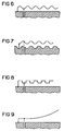
- FIGS 5a to 5m show a small sample selection of differently designed and linked together Types of antennas according to the present invention. This Selection is by no means restrictive. The same applies here that the Any combination of the coupled antenna types can be.
- the radiating element can be wavy, as shown in FIG is formed, or, as shown in FIG. 8, rectangular meandering.
- FIG. 7 shows, by way of example, that it goes without saying also the ground plate of the shape of the radiator element can adjust.
- the multi-band antenna is not 100 percent parallel for metallic EMC shielding of the radio-operated communication terminal runs, but at one or several places a larger distance between the antenna and the metallic EMC layer. This is an example shown in Figure 9.
- the increase in distance can, for example also occur at the feed point of the antenna.
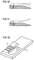
- FIG. 12 is a perspective representation of a principle partially shortened antenna configuration according to the present Invention shown.
- the antenna configuration shown consists of a compressed microstrip antenna 17 and a planar inverted-F antenna 18 which are connected to each other are electrically connected, the supply and the connection with ground via the planar inverted-F antenna.
- parts of the actual radiator elements point the two antennas have different heights or slopes on.
- the invention Antenna the problem underlying the invention resolves that none, one or more planar inverted-F antennas and / or none, one or more planar inverted-L antennas and / or none, one or more microstrip (patch) antennas by coupling to one another to form an antenna system get connected.
- microstrip (patch) antennas by coupling to one another to form an antenna system get connected.
- the present invention is not limited to this.
- the antenna structure is only fed at one point.
- This preferably has a planar inverted-F structure or a planar inverted L structure.
- the coupling between the individual radiator elements can be capacitive, inductive, blasted or be galvanic. Due to the type and number of couplings various parameters of the antenna can be set. For example, are the dimensions for the planar inverted-F antenna and the length of the microstrip antenna the same, the radiation frequencies behave like approx. 1: 2. This can be used as a GSM-PCN antenna.
- This planar antenna structure requires one feed and one or several ground connections, which can be of any shape can do certain antenna properties set.
- the connection points for the supply indicated in the drawings and ground connection can and must also be interchanged not necessarily at the edge or a corner of the spotlight structure lie. They can be positioned so that for all operating frequency ranges a desired impedance behavior is set becomes.
- the antenna can have its own ground plate or else the metallic parts and surfaces of the radio-operated communication terminal use as a ground plate.
- the possibly additional Earth plate can be shaped as desired and does not necessarily have to be adapted to the shape of the radiator element his.
- the individual parts of the radiator element can be different Heights, e.g. through cranking or inclines of the ground plane.
- the antenna can also be adjusted by suitable vertical Structures to be compressed or by suitable Folding can be shortened.
- the type of folds and / or upsets can be executed arbitrarily and can in different technologies can be realized. It can the radiator element alone, but also the associated ground plane be structured accordingly.
- the corresponding shape the radiation properties of the individual radiator elements further change or improve or the antenna adapt to the geometry of the housing. In this case it is e.g. to name grading, slits, tapering, change of Spotlight height above the ground surface.
- the multiband antenna according to the invention is that individual radiator parts, which are used for a planar inverted-F antenna, for example, can also be used for radiation as an inverted-L antenna or as a microstrip antenna. Any combination of radiator elements is possible, and consequently additional resulting antenna structures are possible. These enable radiation in further frequency ranges or can be used to further improve one or more radiation behavior.
- the space or volume requirements can be kept small due to the multiple use of radiator parts.
Abstract
Description
Die vorliegende Erfindung betrifft eine Antenne für funkbetriebene Kommunikationsendgeräte.The present invention relates to an antenna for radio-operated Communication terminals.
Insbesondere in Hinsicht auf die Entwicklung in der Mobilfunktechnologie werden Antennen benötigt, welche in der Lage sind, mehrere Frequenzbänder gleichzeitig abzudecken. Außerdem verlangt der Markt nach immer kleineren und billigeren Mobilfunkgeräten. Deswegen sind Antennen gefordert, die einen geringen Platzbedarf haben, problemlos für eine Funktion in mehreren Frequenzbändern oder einem breitbandigen Frequenzbereich auslegbar und billig herstellbar sind.Especially with regard to the development in mobile radio technology antennas are needed, which are able are to cover several frequency bands at the same time. Moreover the market is asking for smaller and cheaper ones Mobile devices. That is why antennas are required, some have a small footprint, easily for a function in several frequency bands or a broadband frequency range can be designed and manufactured cheaply.
Es sind Lösungen bekannt, bei denen einfach zwei oder mehrere einzelne planare Inverted-F-Antenne in einem Kommunikationsendgerät integriert werden. Dabei sind dann aber mehrere Speisepunkte notwendig, die dann über geeignete Beschaltungen anzusteuern sind, was einen zusätzlichen Aufwand darstellt.Solutions are known in which simply two or more single planar inverted-F antenna in a communication terminal to get integrated. But then there are several Feeding points necessary, which then have suitable circuits are to be controlled, which represents an additional effort.
Aufgabe der vorliegenden Erfindung ist es, eine Antenne für funkbetriebene Kommunikationsendgeräte anzugeben, welche einfach aufgebaut ist und gleichzeitig mehrere Frequenzbänder abdecken kann.The object of the present invention is to provide an antenna for radio-operated communication terminals to specify which simple is built up and simultaneously several frequency bands can cover.
Eine Antenne für funkbetriebene Kommunikationsendgeräte zur Lösung der erfindungsgemäßen Aufgabe ist gekennzeichnet durch eine aus mehreren unterschiedlichen Antennentypen bestehende Kombination, wobei jeder Antennentyp ein- oder mehrfach vorhanden sein kann und wobei die Kombination aus mehreren Antennen jeweils nur an einem Punkt eingespeist wird.An antenna for radio-operated communication terminals for Solution to the problem according to the invention is characterized by one consisting of several different antenna types Combination, where each antenna type exists one or more times can be and where the combination of several antennas is only fed in at one point.
Die erfindungsgemäße Antenne ist leicht und billig herstellbar, erfordert einen geringen Platzbedarf und ist problemlos für eine Funktion in mehreren Frequenzbändern oder in einem breitbandigen Frequenzbereich auslegbar.The antenna according to the invention is easy and inexpensive to manufacture, requires little space and is easy for a function in several frequency bands or in one broadband frequency range can be designed.
Weitere zweckmäßige Ausgestaltungen der erfindungsgemäßen Antenne ergeben sich aus den Unteransprüchen sowie aus einer nachfolgenden Beschreibung von Ausführungsbeispielen anhand der Zeichnungen.Further expedient configurations of the antenna according to the invention result from the subclaims and from a The following description of exemplary embodiments based on of the drawings.
In den Zeichnungen zeigen
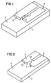
In Figur 1 sind mit 1 und 2 die beiden eigentlichen Antennen,
aus denen die erfindungsgemäße Multiband-Antenne zusammengesetzt
ist, bezeichnet, wobei es sich in dem in Figur 1 dargestellten
Beispiel um eine planare Inverted-F-Antenne 1 und um
eine Patch-Antenne oder Mikrostrip-Antenne 2 handelt. Von dem
Mobilfunkgerät 3 ist lediglich ein Teil der Gehäusewand gezeigt,
welche mit einer metallischen EMV-Schirmung 4 überzogen
ist. Bei der dargestellten Multiband-Antenne bildet diese
metallische EMV- Schirmung die für die beiden Antennen 1 und
2 notwendige Masse.1 and 2 are the two actual antennas in FIG.
from which the multiband antenna according to the invention is composed
is referred to, it being in that shown in Figure 1
Example of a planar inverted-F antenna 1 and
is a patch antenna or
Die Verbindung zwischen dem Strahlerelement der Antenne 1 und
der metallischen EMV- Schirmung 4 wird über die Masseverbindung
5 hergestellt. Der eigentliche Speisepunkt der Antenne
ist mit 6 gekennzeichnet. Mit 7 ist eine symbolische Verkopplung
der beiden Antennen 1 und 2 angedeutet. Diese Verkopplung
kann kapazitiv, induktiv, gestrahlt oder galvanisch
sein. Durch die Art der Kopplung können verschiedene Parameter
der Antenne eingestellt werden.The connection between the radiator element of the antenna 1 and
the metallic EMC
Bezüglich der in Figur 1 dargestellten Antennenkonfiguration ist festzustellen, daß die Masseverbindung 5 auch punktuell, sowie mehrfach punktuell möglich ist. With regard to the antenna configuration shown in Figure 1 it should be noted that the ground connection 5 is also selective, as well as several times is possible.
Figur 2 zeigt nun eine perspektivische Prinzipdarstellung einer
Multiband-Antenne gemäß der vorliegenden Erfindung, welche
aus einer planaren Inverted-F-Antenne 8 und einer planaren
Inverted-L-Antenne 9 besteht. Im vorliegenden Falle sind
die beiden Antennen 8 und 9 über eine galvanische Verkopplung
10 miteinander verkoppelt. Die Speisung der Multiband-Antenne
erfolgt mittels eines Speisepunktes 11, der mit der planaren
Inverted-L-Antenne 9 verbunden ist. Die Masseverbindung der
dargestellten Antennenkonfiguration erfolgt über die Masseverbindung
12.Figure 2 now shows a perspective representation of a principle
Multiband antenna according to the present invention, which
from a planar inverted-
Figur 3 stellt eine Antennenkonfiguration dar, welche aus einer
Mikrostrip-Antenne 13 und eine mit dieser galvanisch verbundenen
planaren Inverted-L-Antenne 14 besteht. Die Antennenkonfiguration
wird über den Speisepunkt 15 gespeist.FIG. 3 shows an antenna configuration which consists of a
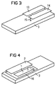
Figur 4 zeigt ein Ausführungsbeispiel einer erfindungsgemäßen
Multibandantenne, bei welcher im Gegensatz zu der in Figur 1
dargestellten Multibandantenne eine zusätzliche separate Masseplatte
16 vorgesehen ist. Da unter normalen Umständen die
Masseverhältnisse innerhalb eines funkbetriebenen Kommunikationsendgerätes
nicht immer voll abschätzbar sind, sorgt die
Masseplatte 16 für definierte Masseverhältnisse in Bezug auf
die Multibandantenne. Zwischen der Masseplatte und der Gerätemasse
können eine oder mehrere Verbindungen vorgesehen
sein.Figure 4 shows an embodiment of an inventive
Multi-band antenna, in which, in contrast to that in FIG. 1
Multiband antenna shown an additional
Die Figuren 5a bis 5m zeigen eine kleine beispielhafte Auswahl von unterschiedlich gestalteten und miteinander verkoppelten Antennentypen gemäß der vorliegenden Erfindung. Diese Auswahl ist keinesfalls beschränkend. Auch hier gilt, daß die Kombination der miteinander verkoppelten Antennentypen beliebig sein kann.Figures 5a to 5m show a small sample selection of differently designed and linked together Types of antennas according to the present invention. This Selection is by no means restrictive. The same applies here that the Any combination of the coupled antenna types can be.
Zur Verkürzung der Einbaulänge der erfindungsgemäßen Antenne kann das Strahlerelement wellenförmig, wie in Figur 6 gezeigt ist, ausgebildet sein, oder, wie in Figur 8 gezeigt ist, rechteckförmig meanderförmig.To shorten the installation length of the antenna according to the invention the radiating element can be wavy, as shown in FIG is formed, or, as shown in FIG. 8, rectangular meandering.
In Figur 7 ist beispielshaft dargestellt, daß sich selbstverständlich auch die Masseplatte der Form des Strahlerelements anpassen kann.FIG. 7 shows, by way of example, that it goes without saying also the ground plate of the shape of the radiator element can adjust.
Zur Verbesserung der Abstrahleigenschaften und der Bandbreitenerhöhung kann vorgesehen sein, daß die Ebene des Strahlerelements der Multibandantenne nicht hundertprozentig parallel zur metallischen EMV-Schirmung des funkbetriebenen Kommunikationsendgerätes verläuft, sondern sich an einer oder mehrerer Stellen ein größerer Abstand zwischen der Antenne und der metallischen EMV-Schicht bildet. Dies ist beispielhaft in Figur 9 dargestellt. Die Abstandserhöhung kann beispielsweise auch am Speisepunkt der Antenne auftreten.To improve the radiation properties and increase the bandwidth can be provided that the plane of the radiator element the multi-band antenna is not 100 percent parallel for metallic EMC shielding of the radio-operated communication terminal runs, but at one or several places a larger distance between the antenna and the metallic EMC layer. This is an example shown in Figure 9. The increase in distance can, for example also occur at the feed point of the antenna.
Die gleiche Problematik ist in Figur 10 dargestellt, wobei davon ausgegangen wird, daß sich normalerweise die Ebene des Strahlerelements der Multibandantenne dem Gehäuseverlauf anpaßt - in Figur 10 gestrichelt dargestellt -, aber um die Abstrahleigenschaften zu verbessern, geradlinig weitergeführt werden kann.The same problem is shown in Figure 10, wherein it is assumed that the level of the Radiator element of the multi-band antenna adapts to the course of the housing - shown in dashed lines in Figure 10 -, but about the radiation properties to improve, continued in a straight line can be.
Eine weitere Möglichkeit zu Verbesserung der Abstrahleigenschaften der Antenne ist prinzipiell in Figur 11 dargestellt.Another way to improve the radiation properties the antenna is shown in principle in Figure 11.
In Figur 12 ist eine perspektivische Prinzipdarstellung einer
teilweise verkürzten Antennenkonfiguration gemäß der vorliegenden
Erfindung dargestellt. Die dargestellte Antennenkonfiguration
besteht aus einer gestauchten Mikrostrip-Antenne 17
und einer planaren Inverted-F-Antenne 18, welche miteinander
galvanisch verbunden sind, wobei die Speisung und die Verbindung
mit Masse über die planare Inverted-F-Antenne erfolgt.
Gleichzeitig weisen Teile der eigentlichen Strahlerelemente
der beiden Antennen unterschiedliche Höhen, bzw. Steigungen
auf.FIG. 12 is a perspective representation of a principle
partially shortened antenna configuration according to the present
Invention shown. The antenna configuration shown
consists of a
Zusammenhängend ist festzustellen, daß die erfindungsgemäße Antenne das der Erfindung zugrundeliegende Problem dadurch löst, daß keine, eine oder mehrere planare Inverted-F-Antennen und/oder keine, eine oder mehrere planare Inverted-L-Antennen und/oder keine, eine oder mehrere Mikrostrip-(Patch)-Antennen durch Kopplung zu einem Antennensystem miteinander verbunden werden. In den vorstehend dargestellten Ausführungsbeispielen sind lediglich aus zwei unterschiedlichen Antennen bestehende Antennensysteme dargestellt. Jedoch ist die vorliegende Erfindung nicht darauf beschränkt.In context, it should be noted that the invention Antenna the problem underlying the invention resolves that none, one or more planar inverted-F antennas and / or none, one or more planar inverted-L antennas and / or none, one or more microstrip (patch) antennas by coupling to one another to form an antenna system get connected. In the above Embodiments are only two different Antennas existing antenna systems shown. However the present invention is not limited to this.
Gespeist wird die Antennenstruktur nur an einem Punkt. Dieser besitzt vorzugsweise eine planare Inverted-F-Struktur oder eine planare Inverted-L-Struktur. Es sind aber auch Lösungen denkbar, bei denen die Einspeisung über eine Mikrostrip-Struktur erfolgt. Die Kopplung zwischen den einzelnen Strahlerelementen kann dabei kapazitiv, induktiv, gestrahlt oder galvanisch sein. Durch die Art und Anzahl der Kopplungen können verschiedene Parameter der Antenne eingestellt werden. Sind beispielsweise die Abmessungen für die planare Inverted-F-Antenne und die Mikrostrip-Antenne etwa von der Länge her gleich, verhalten sich die Strahlungsfrequenzen wie ca. 1:2. Dieses kann beim Einsatz als GSM-PCN-Antenne genutzt werden.The antenna structure is only fed at one point. This preferably has a planar inverted-F structure or a planar inverted L structure. But they are also solutions conceivable, in which the feed via a microstrip structure he follows. The coupling between the individual radiator elements can be capacitive, inductive, blasted or be galvanic. Due to the type and number of couplings various parameters of the antenna can be set. For example, are the dimensions for the planar inverted-F antenna and the length of the microstrip antenna the same, the radiation frequencies behave like approx. 1: 2. This can be used as a GSM-PCN antenna.
Durch geeignete Gestaltung der Strahlerelemente-Kombination kann ein Teil davon für zwei oder mehrere Frequenzbereiche benutzt werden, und dadurch können die Gesamtabmessungen des Antennensystems kleingehalten werden. Durch Querresonanzen zwischen den verschiedenen Strahlerteilen kann es zu zusätzlichen Abstrahlungen bei weiteren Frequenzen kommen.By suitable design of the combination of radiator elements can be a part of it for two or more frequency ranges can be used, and thereby the overall dimensions of the Antenna systems are kept small. Through cross-resonance there may be additional ones between the different parts of the heater Radiations come at other frequencies.
Diese planare Antennenstruktur benötigt eine Speise- und eine oder mehrere Masseanbindungen, die beliebig ausgeformt sein können, tun bestimmte Antenneneigenschaften einzustellen. Die in den Zeichnungen angegebenen Anschlußpunkte für die Speisung und Masseanbindung können auch vertauscht sein und müssen nicht zwingend am Rand oder eine Ecke der Strahlerstruktur liegen. Sie sind so positionierbar, daß für alle Betriebsfrequenzbereiche ein gewünschtes Impedanzverhalten eingestellt wird.This planar antenna structure requires one feed and one or several ground connections, which can be of any shape can do certain antenna properties set. The connection points for the supply indicated in the drawings and ground connection can and must also be interchanged not necessarily at the edge or a corner of the spotlight structure lie. They can be positioned so that for all operating frequency ranges a desired impedance behavior is set becomes.
Die Antenne kann ihre eigene Masseplatte besitzen oder auch die metallischen Teile und Flächen des funkbetriebenen Kommunikationsendgeräts als Masseplatte benutzen. Die evtl. zusätzliche Masseplatte kann dabei beliebig ausgeformt sein und muß nicht zwingend an die Form des Strahlerelementes angepaßt sein.The antenna can have its own ground plate or else the metallic parts and surfaces of the radio-operated communication terminal use as a ground plate. The possibly additional Earth plate can be shaped as desired and does not necessarily have to be adapted to the shape of the radiator element his.
Die einzelnen Teile des Strahlerelements können unterschiedliche Höhen, z.B. durch Kröpfung oder Steigungen, gegenüber der Massefläche aufweisen. Zur Verringerung der Abmessungen in Längsrichtung kann die Antenne auch durch geeignete vertikale Strukturierung gestaucht werden oder durch geeignete Faltung verkürzt werden. Die Art der Faltungen und/oder Stauchungen können dabei beliebig ausgeführt werden und können in unterschiedlichen Technologien realisiert werden. Dabei kann das Strahlerelement allein, aber auch die zugehörige Massefläche entsprechend strukturiert sein. Die entsprechende Ausformung der einzelnen Strahlerelemente können die Abstrahleigenschaften weiter verändern bzw. verbessern oder die Antenne an die Geometrie des Gehäuses anpassen. In diesem Falle ist z.B. zu nennen Stufung, Schlitze, Taperung, Veränderung der Strahlerhöhe über der Massefläche.The individual parts of the radiator element can be different Heights, e.g. through cranking or inclines of the ground plane. To reduce the dimensions in the longitudinal direction, the antenna can also be adjusted by suitable vertical Structures to be compressed or by suitable Folding can be shortened. The type of folds and / or upsets can be executed arbitrarily and can in different technologies can be realized. It can the radiator element alone, but also the associated ground plane be structured accordingly. The corresponding shape the radiation properties of the individual radiator elements further change or improve or the antenna adapt to the geometry of the housing. In this case it is e.g. to name grading, slits, tapering, change of Spotlight height above the ground surface.
Aus mechanischen Gründen bzw. zur Verbesserung der Abstrahleigenschaften
oder optimalen Ausnutzung eines verfügbaren Volumens
ist es ebenfalls möglich, geeignete dielektrische oder
magnetische Materialien in die Antennenstruktur einzubringen.
Diese können die Antennenstruktur teilweise aber auch vollständig
ausfüllen. Es sich auch Kombinationen von verschiedenen
dielektrischen und/oder magnetischen Stoffen bzw. Luft
möglich.
Der Vorteil der erfindungsgemäßen Multiband-Antenne liegt
darin, daß einzelne Strahlerteile, die für z.B. ein planare
Inverted-F-Antenne genutzt werden, auch zur Abstrahlung als
eine Inverted-L-Antenne oder als eine Mikrostrip-Antenne genutzt
werden können. Dabei sind beliebige Kombinationen von
Strahlerelementen möglich und folglich zusätzliche sich ergebende
Antennenstrukturen möglich. Diese ermöglichen eine Abstrahlung
in weiteren Frequenzbereichen oder können zur weiteren
Verbesserung eines oder mehrerer Abstrahlungsverhalten
genutzt werden. Durch die mehrfach mögliche Nutzung von
Strahlerteilen kann der Flächenbedarf bzw. Volumenbedarf
kleingehalten werden. Da man am einzigen Fußpunkt, d.h. dem
Speisepunkt, der Antenne eine Impedanz von beispielsweise 50
Ohm für alle Frequenzbereiche einstellen kann, ist keine weitere
Beschaltung mehr nötig. Die Verluste in einem sonst
evtl. nötigen Speisenetzwerk entfallen somit. Da bei den erfindungsgemäßen
Antennen je nach Frequenzbereich unterschiedliche
Teile zur Strahlung beitragen, werden bei einer versehentlich
teilweisen Abdeckung der Antenne mit der Hand nicht
alle Frequenzbereiche gleichermaßen gestört. Eine bestehende
Gesprächsverbindung kann folglich ggf. in einem ungestörten
Frequenzbereich aufrechterhalten werden.For mechanical reasons or to improve the radiation properties or optimal use of an available volume, it is also possible to introduce suitable dielectric or magnetic materials into the antenna structure. However, some of these can also completely fill the antenna structure. Combinations of different dielectric and / or magnetic substances or air are also possible.
The advantage of the multiband antenna according to the invention is that individual radiator parts, which are used for a planar inverted-F antenna, for example, can also be used for radiation as an inverted-L antenna or as a microstrip antenna. Any combination of radiator elements is possible, and consequently additional resulting antenna structures are possible. These enable radiation in further frequency ranges or can be used to further improve one or more radiation behavior. The space or volume requirements can be kept small due to the multiple use of radiator parts. Since you can set an impedance of, for example, 50 ohms for all frequency ranges at the only base point, ie the feed point, of the antenna, no further wiring is necessary. The losses in an otherwise necessary dining network are thus eliminated. Since different parts of the antennas according to the invention contribute to the radiation depending on the frequency range, not all frequency ranges are equally disturbed if the antenna is accidentally partially covered by hand. An existing call connection can consequently be maintained in an undisturbed frequency range.
Claims (17)
Applications Claiming Priority (2)
| Application Number | Priority Date | Filing Date | Title |
|---|---|---|---|
| DE19903004 | 1999-01-26 | ||
| DE19903004 | 1999-01-26 |
Publications (2)
| Publication Number | Publication Date |
|---|---|
| EP1024552A2 true EP1024552A2 (en) | 2000-08-02 |
| EP1024552A3 EP1024552A3 (en) | 2003-05-07 |
Family
ID=7895418
Family Applications (1)
| Application Number | Title | Priority Date | Filing Date |
|---|---|---|---|
| EP00100221A Withdrawn EP1024552A3 (en) | 1999-01-26 | 2000-01-14 | Antenna for radio communication terminals |
Country Status (2)
| Country | Link |
|---|---|
| US (1) | US20010050636A1 (en) |
| EP (1) | EP1024552A3 (en) |
Cited By (33)
| Publication number | Priority date | Publication date | Assignee | Title |
|---|---|---|---|---|
| EP1096602A1 (en) * | 1999-11-01 | 2001-05-02 | Filtronic LK Oy | Planar antenna |
| EP1128466A2 (en) * | 2000-02-24 | 2001-08-29 | Filtronic LK Oy | Planar antenna structure |
| WO2002005381A1 (en) * | 2000-07-10 | 2002-01-17 | Allgon Mobile Communications Ab | Antenna arrangement and portable radio communication device |
| WO2002013307A1 (en) * | 2000-08-07 | 2002-02-14 | Telefonaktiebolaget L M Ericsson | Antenna |
| DE10039772A1 (en) * | 2000-08-16 | 2002-03-07 | Bosch Gmbh Robert | combination antenna |
| WO2002049148A2 (en) * | 2000-12-15 | 2002-06-20 | Atheros Communications, Inc. | Methods of manufacturing and mounting a side stem or central-stem monopole antenna |
| FR2823909A1 (en) * | 2001-04-23 | 2002-10-25 | Framatome Connectors Int | Three band mobile telephone antenna block having radiation zone/transition zone superimposed/metallic return electrically connected with transition zone width progressively/autonomously increasing along propagation direction. |
| WO2002087015A1 (en) * | 2001-04-23 | 2002-10-31 | Fci | Compact antenna block for a wireless device |
| WO2003009417A1 (en) * | 2001-07-20 | 2003-01-30 | Actipass Co., Ltd. | Battery antenna for portable wireless communication terminal |
| US6538605B2 (en) | 2000-12-15 | 2003-03-25 | Atheros Communications, Inc. | Method and system for mounting a monopole antenna |
| EP1306923A1 (en) * | 2000-08-04 | 2003-05-02 | Matsushita Electric Industrial Co., Ltd. | Antenna device and radio communication device comprising the same |
| EP1233426A3 (en) * | 2001-02-15 | 2003-07-09 | Integral Technologies, Inc. | Antennas with conductive plastics or conductive composites |
| US6650294B2 (en) | 2001-11-26 | 2003-11-18 | Telefonaktiebolaget Lm Ericsson (Publ) | Compact broadband antenna |
| US6718619B2 (en) | 2000-12-15 | 2004-04-13 | Atheros Communications, Inc. | Method of manufacturing a central stem monopole antenna |
| EP1443596A1 (en) * | 2003-01-29 | 2004-08-04 | Integral Technologies, Inc. | Multi-segmented planar antenna with built-in ground plane |
| DE10302805A1 (en) * | 2003-01-24 | 2004-08-12 | Siemens Ag | Multi-band antenna arrangement for mobile radio devices |
| DE10328361A1 (en) * | 2003-06-24 | 2005-01-20 | Siemens Ag | PIFA antenna arrangement for several mobile radio frequency bands |
| US6870516B2 (en) | 2001-02-16 | 2005-03-22 | Integral Technologies, Inc. | Low cost antennas using conductive plastics or conductive composites |
| US6883227B2 (en) | 2000-12-15 | 2005-04-26 | Atheros Communications, Inc. | Method of manufacturing a side stem monopole antenna |
| EP1579529A2 (en) * | 2002-12-17 | 2005-09-28 | Ethertronics, Inc. | Antennas with reduced space and improved performance |
| DE102004027692A1 (en) * | 2004-03-10 | 2005-10-06 | Daimlerchrysler Ag | Use of an inverted L antenna in a motor vehicle |
| WO2005109570A1 (en) * | 2004-05-11 | 2005-11-17 | Benq Mobile Gmbh & Co. Ohg | A portable radio device |
| US7102575B2 (en) | 2000-11-24 | 2006-09-05 | Siemens Aktiengesellschaft | PIFA antenna apparatus for mobile communications terminals |
| US7295160B2 (en) | 2002-03-08 | 2007-11-13 | Koninklijke Philips Electronics N.V. | Multiband microwave antenna |
| US7486242B2 (en) | 2002-06-25 | 2009-02-03 | Fractus, S.A. | Multiband antenna for handheld terminal |
| EP2302732A1 (en) * | 2009-09-18 | 2011-03-30 | Aisin Seiki Kabushiki Kaisha | Multi-frequency antenna |
| US8268222B2 (en) | 2001-02-15 | 2012-09-18 | Integral Technologies, Inc. | Methods of making electrical motor components from conductive loaded resin-based materials |
| EP2509155A1 (en) * | 2011-04-06 | 2012-10-10 | Research In Motion Limited | Mobile wireless communications device having antenna assembly with electrically conductive base enclosing an elongate slot and associated methods |
| US8377585B2 (en) | 2001-02-15 | 2013-02-19 | Integral Technologies, Inc. | Low cost electrical terminals manufactured from conductive loaded resin-based materials |
| US8610627B2 (en) | 2000-01-19 | 2013-12-17 | Fractus, S.A. | Space-filling miniature antennas |
| US8738103B2 (en) | 2006-07-18 | 2014-05-27 | Fractus, S.A. | Multiple-body-configuration multimedia and smartphone multifunction wireless devices |
| US9761934B2 (en) | 1999-09-20 | 2017-09-12 | Fractus, S.A. | Multilevel antennae |
| CN112751182A (en) * | 2020-12-28 | 2021-05-04 | Oppo广东移动通信有限公司 | Antenna assembly and electronic equipment |
Families Citing this family (47)
| Publication number | Priority date | Publication date | Assignee | Title |
|---|---|---|---|---|
| FI113813B (en) | 2001-04-02 | 2004-06-15 | Nokia Corp | Electrically tunable multiband antenna |
| US9755314B2 (en) | 2001-10-16 | 2017-09-05 | Fractus S.A. | Loaded antenna |
| TWI258246B (en) * | 2002-03-14 | 2006-07-11 | Sony Ericsson Mobile Comm Ab | Flat built-in radio antenna |
| EP1345282B1 (en) * | 2002-03-14 | 2006-01-18 | Sony Ericsson Mobile Communications AB | Multiband planar built-in radio antenna with inverted-l main and parasitic radiators |
| CN100380737C (en) * | 2002-03-28 | 2008-04-09 | 松下电器产业株式会社 | Antenna and electronic apparatus using it |
| JP2006510321A (en) | 2002-12-22 | 2006-03-23 | フラクタス・ソシエダッド・アノニマ | Multiband monopole antenna for mobile communication devices |
| EP1536242A1 (en) * | 2003-11-28 | 2005-06-01 | Maschek Elekronik | Dosimeter for electromagnetic fields |
| EP1709704A2 (en) | 2004-01-30 | 2006-10-11 | Fractus, S.A. | Multi-band monopole antennas for mobile communications devices |
| DE102004036001A1 (en) * | 2004-07-23 | 2006-03-16 | Eads Deutschland Gmbh | Broadband antenna with low height |
| KR100761931B1 (en) * | 2004-12-06 | 2007-09-28 | 엘지전자 주식회사 | flush-mounted Antenna |
| US20060192757A1 (en) * | 2005-02-28 | 2006-08-31 | Chic Technology Corp. | Receiver accommodative wireless input equipment |
| FI20055420A0 (en) | 2005-07-25 | 2005-07-25 | Lk Products Oy | Adjustable multi-band antenna |
| FI119009B (en) | 2005-10-03 | 2008-06-13 | Pulse Finland Oy | Multiple-band antenna |
| FI118782B (en) | 2005-10-14 | 2008-03-14 | Pulse Finland Oy | Adjustable antenna |
| US8618990B2 (en) | 2011-04-13 | 2013-12-31 | Pulse Finland Oy | Wideband antenna and methods |
| FI20075269A0 (en) | 2007-04-19 | 2007-04-19 | Pulse Finland Oy | Method and arrangement for antenna matching |
| US20090005110A1 (en) * | 2007-06-29 | 2009-01-01 | Nokia Corporation | Using a conductive support of a speaker assembly as an antenna |
| FI120427B (en) | 2007-08-30 | 2009-10-15 | Pulse Finland Oy | Adjustable multiband antenna |
| CN101677148B (en) * | 2008-09-16 | 2013-02-13 | 鸿富锦精密工业(深圳)有限公司 | Multifrequency antenna |
| US8174457B1 (en) | 2009-01-23 | 2012-05-08 | RadioShack, Corporation | Broadband television antenna |
| FI20096134A0 (en) | 2009-11-03 | 2009-11-03 | Pulse Finland Oy | Adjustable antenna |
| FI20096251A0 (en) | 2009-11-27 | 2009-11-27 | Pulse Finland Oy | MIMO antenna |
| US8847833B2 (en) | 2009-12-29 | 2014-09-30 | Pulse Finland Oy | Loop resonator apparatus and methods for enhanced field control |
| FI20105158A (en) | 2010-02-18 | 2011-08-19 | Pulse Finland Oy | SHELL RADIATOR ANTENNA |
| US9406998B2 (en) | 2010-04-21 | 2016-08-02 | Pulse Finland Oy | Distributed multiband antenna and methods |
| FI20115072A0 (en) | 2011-01-25 | 2011-01-25 | Pulse Finland Oy | Multi-resonance antenna, antenna module and radio unit |
| US9673507B2 (en) | 2011-02-11 | 2017-06-06 | Pulse Finland Oy | Chassis-excited antenna apparatus and methods |
| US8648752B2 (en) | 2011-02-11 | 2014-02-11 | Pulse Finland Oy | Chassis-excited antenna apparatus and methods |
| US8866689B2 (en) | 2011-07-07 | 2014-10-21 | Pulse Finland Oy | Multi-band antenna and methods for long term evolution wireless system |
| US9450291B2 (en) | 2011-07-25 | 2016-09-20 | Pulse Finland Oy | Multiband slot loop antenna apparatus and methods |
| US9123990B2 (en) | 2011-10-07 | 2015-09-01 | Pulse Finland Oy | Multi-feed antenna apparatus and methods |
| US9531058B2 (en) | 2011-12-20 | 2016-12-27 | Pulse Finland Oy | Loosely-coupled radio antenna apparatus and methods |
| US9484619B2 (en) | 2011-12-21 | 2016-11-01 | Pulse Finland Oy | Switchable diversity antenna apparatus and methods |
| US8988296B2 (en) | 2012-04-04 | 2015-03-24 | Pulse Finland Oy | Compact polarized antenna and methods |
| US9979078B2 (en) | 2012-10-25 | 2018-05-22 | Pulse Finland Oy | Modular cell antenna apparatus and methods |
| US10069209B2 (en) | 2012-11-06 | 2018-09-04 | Pulse Finland Oy | Capacitively coupled antenna apparatus and methods |
| US9647338B2 (en) | 2013-03-11 | 2017-05-09 | Pulse Finland Oy | Coupled antenna structure and methods |
| US10079428B2 (en) | 2013-03-11 | 2018-09-18 | Pulse Finland Oy | Coupled antenna structure and methods |
| US9711863B2 (en) * | 2013-03-13 | 2017-07-18 | Microsoft Technology Licensing, Llc | Dual band WLAN coupled radiator antenna |
| US9634383B2 (en) | 2013-06-26 | 2017-04-25 | Pulse Finland Oy | Galvanically separated non-interacting antenna sector apparatus and methods |
| US9680212B2 (en) | 2013-11-20 | 2017-06-13 | Pulse Finland Oy | Capacitive grounding methods and apparatus for mobile devices |
| US9590308B2 (en) | 2013-12-03 | 2017-03-07 | Pulse Electronics, Inc. | Reduced surface area antenna apparatus and mobile communications devices incorporating the same |
| US9350081B2 (en) | 2014-01-14 | 2016-05-24 | Pulse Finland Oy | Switchable multi-radiator high band antenna apparatus |
| US9948002B2 (en) | 2014-08-26 | 2018-04-17 | Pulse Finland Oy | Antenna apparatus with an integrated proximity sensor and methods |
| US9973228B2 (en) | 2014-08-26 | 2018-05-15 | Pulse Finland Oy | Antenna apparatus with an integrated proximity sensor and methods |
| US9722308B2 (en) | 2014-08-28 | 2017-08-01 | Pulse Finland Oy | Low passive intermodulation distributed antenna system for multiple-input multiple-output systems and methods of use |
| US9906260B2 (en) | 2015-07-30 | 2018-02-27 | Pulse Finland Oy | Sensor-based closed loop antenna swapping apparatus and methods |
Citations (4)
| Publication number | Priority date | Publication date | Assignee | Title |
|---|---|---|---|---|
| EP0669672A1 (en) * | 1994-02-24 | 1995-08-30 | Ascom Business Systems Ag | Portable radio apparatus |
| GB2288284A (en) * | 1994-04-01 | 1995-10-11 | France Telecom | Antenna with a radiating element and a shaped resonating element |
| US5760745A (en) * | 1995-05-29 | 1998-06-02 | Mitsubishi Denki Kabushiki Kaisha | Electrostatic capacitively coupled antenna device |
| US5764190A (en) * | 1996-07-15 | 1998-06-09 | The Hong Kong University Of Science & Technology | Capacitively loaded PIFA |
-
2000
- 2000-01-14 EP EP00100221A patent/EP1024552A3/en not_active Withdrawn
- 2000-01-26 US US09/491,611 patent/US20010050636A1/en not_active Abandoned
Patent Citations (4)
| Publication number | Priority date | Publication date | Assignee | Title |
|---|---|---|---|---|
| EP0669672A1 (en) * | 1994-02-24 | 1995-08-30 | Ascom Business Systems Ag | Portable radio apparatus |
| GB2288284A (en) * | 1994-04-01 | 1995-10-11 | France Telecom | Antenna with a radiating element and a shaped resonating element |
| US5760745A (en) * | 1995-05-29 | 1998-06-02 | Mitsubishi Denki Kabushiki Kaisha | Electrostatic capacitively coupled antenna device |
| US5764190A (en) * | 1996-07-15 | 1998-06-09 | The Hong Kong University Of Science & Technology | Capacitively loaded PIFA |
Cited By (53)
| Publication number | Priority date | Publication date | Assignee | Title |
|---|---|---|---|---|
| US10056682B2 (en) | 1999-09-20 | 2018-08-21 | Fractus, S.A. | Multilevel antennae |
| US9761934B2 (en) | 1999-09-20 | 2017-09-12 | Fractus, S.A. | Multilevel antennae |
| EP1096602A1 (en) * | 1999-11-01 | 2001-05-02 | Filtronic LK Oy | Planar antenna |
| US8610627B2 (en) | 2000-01-19 | 2013-12-17 | Fractus, S.A. | Space-filling miniature antennas |
| US10355346B2 (en) | 2000-01-19 | 2019-07-16 | Fractus, S.A. | Space-filling miniature antennas |
| US6922171B2 (en) | 2000-02-24 | 2005-07-26 | Filtronic Lk Oy | Planar antenna structure |
| EP1128466A3 (en) * | 2000-02-24 | 2003-09-17 | Filtronic LK Oy | Planar antenna structure |
| EP1128466A2 (en) * | 2000-02-24 | 2001-08-29 | Filtronic LK Oy | Planar antenna structure |
| WO2002005381A1 (en) * | 2000-07-10 | 2002-01-17 | Allgon Mobile Communications Ab | Antenna arrangement and portable radio communication device |
| US6894649B2 (en) | 2000-07-10 | 2005-05-17 | Amc Centurion Ab | Antenna arrangement and portable radio communication device |
| EP1306923A4 (en) * | 2000-08-04 | 2005-04-13 | Matsushita Electric Ind Co Ltd | Antenna device and radio communication device comprising the same |
| EP1306923A1 (en) * | 2000-08-04 | 2003-05-02 | Matsushita Electric Industrial Co., Ltd. | Antenna device and radio communication device comprising the same |
| WO2002013307A1 (en) * | 2000-08-07 | 2002-02-14 | Telefonaktiebolaget L M Ericsson | Antenna |
| US6614400B2 (en) | 2000-08-07 | 2003-09-02 | Telefonaktiebolaget Lm Ericsson (Publ) | Antenna |
| DE10039772A1 (en) * | 2000-08-16 | 2002-03-07 | Bosch Gmbh Robert | combination antenna |
| US7102575B2 (en) | 2000-11-24 | 2006-09-05 | Siemens Aktiengesellschaft | PIFA antenna apparatus for mobile communications terminals |
| WO2002049148A2 (en) * | 2000-12-15 | 2002-06-20 | Atheros Communications, Inc. | Methods of manufacturing and mounting a side stem or central-stem monopole antenna |
| US6718619B2 (en) | 2000-12-15 | 2004-04-13 | Atheros Communications, Inc. | Method of manufacturing a central stem monopole antenna |
| WO2002049148A3 (en) * | 2000-12-15 | 2003-05-01 | Atheros Comm Inc | Methods of manufacturing and mounting a side stem or central-stem monopole antenna |
| US6538605B2 (en) | 2000-12-15 | 2003-03-25 | Atheros Communications, Inc. | Method and system for mounting a monopole antenna |
| US6883227B2 (en) | 2000-12-15 | 2005-04-26 | Atheros Communications, Inc. | Method of manufacturing a side stem monopole antenna |
| US8377585B2 (en) | 2001-02-15 | 2013-02-19 | Integral Technologies, Inc. | Low cost electrical terminals manufactured from conductive loaded resin-based materials |
| EP1233426A3 (en) * | 2001-02-15 | 2003-07-09 | Integral Technologies, Inc. | Antennas with conductive plastics or conductive composites |
| US8268222B2 (en) | 2001-02-15 | 2012-09-18 | Integral Technologies, Inc. | Methods of making electrical motor components from conductive loaded resin-based materials |
| US6741221B2 (en) | 2001-02-15 | 2004-05-25 | Integral Technologies, Inc. | Low cost antennas using conductive plastics or conductive composites |
| US6870516B2 (en) | 2001-02-16 | 2005-03-22 | Integral Technologies, Inc. | Low cost antennas using conductive plastics or conductive composites |
| FR2823909A1 (en) * | 2001-04-23 | 2002-10-25 | Framatome Connectors Int | Three band mobile telephone antenna block having radiation zone/transition zone superimposed/metallic return electrically connected with transition zone width progressively/autonomously increasing along propagation direction. |
| WO2002087015A1 (en) * | 2001-04-23 | 2002-10-31 | Fci | Compact antenna block for a wireless device |
| US7199755B2 (en) | 2001-04-23 | 2007-04-03 | Fci | Compact antenna block for a wireless device |
| WO2003009417A1 (en) * | 2001-07-20 | 2003-01-30 | Actipass Co., Ltd. | Battery antenna for portable wireless communication terminal |
| US6650294B2 (en) | 2001-11-26 | 2003-11-18 | Telefonaktiebolaget Lm Ericsson (Publ) | Compact broadband antenna |
| US7295160B2 (en) | 2002-03-08 | 2007-11-13 | Koninklijke Philips Electronics N.V. | Multiband microwave antenna |
| US7486242B2 (en) | 2002-06-25 | 2009-02-03 | Fractus, S.A. | Multiband antenna for handheld terminal |
| US7903037B2 (en) | 2002-06-25 | 2011-03-08 | Fractus, S.A. | Multiband antenna for handheld terminal |
| EP1579529A4 (en) * | 2002-12-17 | 2007-09-19 | Ethertronics Inc | Antennas with reduced space and improved performance |
| EP1579529A2 (en) * | 2002-12-17 | 2005-09-28 | Ethertronics, Inc. | Antennas with reduced space and improved performance |
| US7999743B2 (en) | 2003-01-24 | 2011-08-16 | Hewlett-Packard Development Company, L.P. | Multiband antenna array for mobile radio equipment |
| DE10302805A1 (en) * | 2003-01-24 | 2004-08-12 | Siemens Ag | Multi-band antenna arrangement for mobile radio devices |
| CN1298080C (en) * | 2003-01-29 | 2007-01-31 | 整合技术有限公司 | Multi-fold flat antenna with built-in ground connection |
| EP1443596A1 (en) * | 2003-01-29 | 2004-08-04 | Integral Technologies, Inc. | Multi-segmented planar antenna with built-in ground plane |
| DE10328361A1 (en) * | 2003-06-24 | 2005-01-20 | Siemens Ag | PIFA antenna arrangement for several mobile radio frequency bands |
| DE102004027692A1 (en) * | 2004-03-10 | 2005-10-06 | Daimlerchrysler Ag | Use of an inverted L antenna in a motor vehicle |
| WO2005109570A1 (en) * | 2004-05-11 | 2005-11-17 | Benq Mobile Gmbh & Co. Ohg | A portable radio device |
| US11735810B2 (en) | 2006-07-18 | 2023-08-22 | Fractus, S.A. | Multiple-body-configuration multimedia and smartphone multifunction wireless devices |
| US11031677B2 (en) | 2006-07-18 | 2021-06-08 | Fractus, S.A. | Multiple-body-configuration multimedia and smartphone multifunction wireless devices |
| US8738103B2 (en) | 2006-07-18 | 2014-05-27 | Fractus, S.A. | Multiple-body-configuration multimedia and smartphone multifunction wireless devices |
| US11349200B2 (en) | 2006-07-18 | 2022-05-31 | Fractus, S.A. | Multiple-body-configuration multimedia and smartphone multifunction wireless devices |
| US9899727B2 (en) | 2006-07-18 | 2018-02-20 | Fractus, S.A. | Multiple-body-configuration multimedia and smartphone multifunction wireless devices |
| US10644380B2 (en) | 2006-07-18 | 2020-05-05 | Fractus, S.A. | Multiple-body-configuration multimedia and smartphone multifunction wireless devices |
| EP2302732A1 (en) * | 2009-09-18 | 2011-03-30 | Aisin Seiki Kabushiki Kaisha | Multi-frequency antenna |
| US8933847B2 (en) | 2011-04-06 | 2015-01-13 | Blackberry Limited | Mobile wireless communications device having antenna assembly with electrically conductive base enclosing an elongate slot and associated methods |
| EP2509155A1 (en) * | 2011-04-06 | 2012-10-10 | Research In Motion Limited | Mobile wireless communications device having antenna assembly with electrically conductive base enclosing an elongate slot and associated methods |
| CN112751182A (en) * | 2020-12-28 | 2021-05-04 | Oppo广东移动通信有限公司 | Antenna assembly and electronic equipment |
Also Published As
| Publication number | Publication date |
|---|---|
| EP1024552A3 (en) | 2003-05-07 |
| US20010050636A1 (en) | 2001-12-13 |
Similar Documents
| Publication | Publication Date | Title |
|---|---|---|
| EP1024552A2 (en) | Antenna for radio communication terminals | |
| EP1026774A2 (en) | Antenna for wireless operated communication terminals | |
| EP3635814B1 (en) | Dual-polarised crossed dipole and antenna arrangement having two such dual-polarised crossed dipoles | |
| DE102009051605B4 (en) | Highly integrated multi-band fin antenna for a vehicle | |
| DE10236598B4 (en) | The multi-band built-in antenna | |
| EP1842262B1 (en) | Aperture-coupled antenna | |
| EP2256864B1 (en) | Antenna for circular polarisation with a conductive base | |
| DE102007056258B4 (en) | Chip antenna and associated printed circuit board for a mobile telecommunication device | |
| EP1829158B1 (en) | Disc-monopole antenna structure | |
| DE112015000885B4 (en) | Community antenna device | |
| WO2006000116A1 (en) | Broadband patch antenna | |
| EP3025394B1 (en) | Broadband omnidirectional antenna | |
| EP3178129B1 (en) | Multi-structure broadband monopole antenna for two frequency bands in the decimeter wave range separated by a frequency gap, for motor vehicles | |
| DE102005015561A1 (en) | Broadband internal antenna for mobile communication terminal, has radiator with conductive stripline through which current flows to form current paths in different directions to set certain broadband using electromagnetic coupling | |
| EP2784874B1 (en) | Broadband monopole antenna for vehicles for two frequency bands separated by a frequency gap in the decimeter wavelength | |
| DE10350034A1 (en) | Antenna arrangement in particular for radar applications in motor vehicles | |
| DE10304911A1 (en) | Combination antenna arrangement for several radio services for vehicles | |
| DE10022107A1 (en) | Integrated antenna for mobile phones | |
| DE102005055345A1 (en) | Multiband omnidirectional | |
| DE10346847B4 (en) | microwave antenna | |
| EP1812988B1 (en) | Planar wideband antenna | |
| DE102017101676A1 (en) | Broadband dual polarized omnidirectional antenna | |
| DE102022109407A1 (en) | Antenna element for wireless communication | |
| DE102008019366B3 (en) | Multilayer antenna of planar design | |
| EP1198026A2 (en) | Antenna arrangement for mobile phones |
Legal Events
| Date | Code | Title | Description |
|---|---|---|---|
| PUAI | Public reference made under article 153(3) epc to a published international application that has entered the european phase |
Free format text: ORIGINAL CODE: 0009012 |
|
| AK | Designated contracting states |
Kind code of ref document: A2 Designated state(s): AT BE CH CY DE DK ES FI FR GB GR IE IT LI LU MC NL PT SE |
|
| AX | Request for extension of the european patent |
Free format text: AL;LT;LV;MK;RO;SI |
|
| PUAL | Search report despatched |
Free format text: ORIGINAL CODE: 0009013 |
|
| AK | Designated contracting states |
Designated state(s): AT BE CH CY DE DK ES FI FR GB GR IE IT LI LU MC NL PT SE |
|
| AX | Request for extension of the european patent |
Extension state: AL LT LV MK RO SI |
|
| 17P | Request for examination filed |
Effective date: 20031103 |
|
| 17Q | First examination report despatched |
Effective date: 20031205 |
|
| AKX | Designation fees paid |
Designated state(s): AT BE CH CY DE DK ES FI FR GB GR IE IT LI LU MC NL PT SE |
|
| STAA | Information on the status of an ep patent application or granted ep patent |
Free format text: STATUS: THE APPLICATION IS DEEMED TO BE WITHDRAWN |
|
| 18D | Application deemed to be withdrawn |
Effective date: 20040416 |