EP1030297B1 - An optical disk and an optical disk recording method - Google Patents
An optical disk and an optical disk recording method Download PDFInfo
- Publication number
- EP1030297B1 EP1030297B1 EP00110461A EP00110461A EP1030297B1 EP 1030297 B1 EP1030297 B1 EP 1030297B1 EP 00110461 A EP00110461 A EP 00110461A EP 00110461 A EP00110461 A EP 00110461A EP 1030297 B1 EP1030297 B1 EP 1030297B1
- Authority
- EP
- European Patent Office
- Prior art keywords
- recorded
- area
- barcode
- optical disk
- disk
- Prior art date
- Legal status (The legal status is an assumption and is not a legal conclusion. Google has not performed a legal analysis and makes no representation as to the accuracy of the status listed.)
- Expired - Lifetime
Links
- 230000003287 optical effect Effects 0.000 title claims description 82
- 238000000034 method Methods 0.000 title claims description 46
- 230000000704 physical effect Effects 0.000 claims 1
- 230000008569 process Effects 0.000 description 31
- 238000002310 reflectometry Methods 0.000 description 24
- 238000010586 diagram Methods 0.000 description 20
- 238000004519 manufacturing process Methods 0.000 description 15
- 230000000694 effects Effects 0.000 description 14
- 238000001514 detection method Methods 0.000 description 10
- 238000012937 correction Methods 0.000 description 9
- 238000009966 trimming Methods 0.000 description 9
- 239000010410 layer Substances 0.000 description 6
- 239000000758 substrate Substances 0.000 description 5
- 230000015572 biosynthetic process Effects 0.000 description 3
- 230000007423 decrease Effects 0.000 description 2
- 230000009191 jumping Effects 0.000 description 2
- 238000005259 measurement Methods 0.000 description 2
- 230000000149 penetrating effect Effects 0.000 description 2
- 238000012545 processing Methods 0.000 description 2
- 239000011347 resin Substances 0.000 description 2
- 229920005989 resin Polymers 0.000 description 2
- 239000012790 adhesive layer Substances 0.000 description 1
- 230000004075 alteration Effects 0.000 description 1
- 229910052782 aluminium Inorganic materials 0.000 description 1
- XAGFODPZIPBFFR-UHFFFAOYSA-N aluminium Chemical compound [Al] XAGFODPZIPBFFR-UHFFFAOYSA-N 0.000 description 1
- 238000006243 chemical reaction Methods 0.000 description 1
- 238000010276 construction Methods 0.000 description 1
- 238000005520 cutting process Methods 0.000 description 1
- 230000001419 dependent effect Effects 0.000 description 1
- 238000002474 experimental method Methods 0.000 description 1
- 230000008570 general process Effects 0.000 description 1
- PCHJSUWPFVWCPO-UHFFFAOYSA-N gold Chemical compound [Au] PCHJSUWPFVWCPO-UHFFFAOYSA-N 0.000 description 1
- 229910052737 gold Inorganic materials 0.000 description 1
- 239000010931 gold Substances 0.000 description 1
- 238000010330 laser marking Methods 0.000 description 1
- 229910052751 metal Inorganic materials 0.000 description 1
- 239000002184 metal Substances 0.000 description 1
- 238000007645 offset printing Methods 0.000 description 1
- 230000002265 prevention Effects 0.000 description 1
- 230000005855 radiation Effects 0.000 description 1
- 230000009467 reduction Effects 0.000 description 1
- 230000000630 rising effect Effects 0.000 description 1
- 238000007650 screen-printing Methods 0.000 description 1
- 238000007493 shaping process Methods 0.000 description 1
- 238000004528 spin coating Methods 0.000 description 1
- 238000003860 storage Methods 0.000 description 1
- 230000007306 turnover Effects 0.000 description 1
Images


Classifications
-
- G—PHYSICS
- G11—INFORMATION STORAGE
- G11B—INFORMATION STORAGE BASED ON RELATIVE MOVEMENT BETWEEN RECORD CARRIER AND TRANSDUCER
- G11B23/00—Record carriers not specific to the method of recording or reproducing; Accessories, e.g. containers, specially adapted for co-operation with the recording or reproducing apparatus ; Intermediate mediums; Apparatus or processes specially adapted for their manufacture
- G11B23/38—Visual features other than those contained in record tracks or represented by sprocket holes the visual signals being auxiliary signals
- G11B23/40—Identifying or analogous means applied to or incorporated in the record carrier and not intended for visual display simultaneously with the playing-back of the record carrier, e.g. label, leader, photograph
-
- G—PHYSICS
- G11—INFORMATION STORAGE
- G11B—INFORMATION STORAGE BASED ON RELATIVE MOVEMENT BETWEEN RECORD CARRIER AND TRANSDUCER
- G11B27/00—Editing; Indexing; Addressing; Timing or synchronising; Monitoring; Measuring tape travel
- G11B27/10—Indexing; Addressing; Timing or synchronising; Measuring tape travel
- G11B27/19—Indexing; Addressing; Timing or synchronising; Measuring tape travel by using information detectable on the record carrier
- G11B27/24—Indexing; Addressing; Timing or synchronising; Measuring tape travel by using information detectable on the record carrier by sensing features on the record carrier other than the transducing track ; sensing signals or marks recorded by another method than the main recording
-
- G—PHYSICS
- G06—COMPUTING; CALCULATING OR COUNTING
- G06K—GRAPHICAL DATA READING; PRESENTATION OF DATA; RECORD CARRIERS; HANDLING RECORD CARRIERS
- G06K1/00—Methods or arrangements for marking the record carrier in digital fashion
- G06K1/12—Methods or arrangements for marking the record carrier in digital fashion otherwise than by punching
- G06K1/126—Methods or arrangements for marking the record carrier in digital fashion otherwise than by punching by photographic or thermographic registration
-
- G—PHYSICS
- G06—COMPUTING; CALCULATING OR COUNTING
- G06K—GRAPHICAL DATA READING; PRESENTATION OF DATA; RECORD CARRIERS; HANDLING RECORD CARRIERS
- G06K19/00—Record carriers for use with machines and with at least a part designed to carry digital markings
- G06K19/04—Record carriers for use with machines and with at least a part designed to carry digital markings characterised by the shape
-
- G—PHYSICS
- G06—COMPUTING; CALCULATING OR COUNTING
- G06K—GRAPHICAL DATA READING; PRESENTATION OF DATA; RECORD CARRIERS; HANDLING RECORD CARRIERS
- G06K19/00—Record carriers for use with machines and with at least a part designed to carry digital markings
- G06K19/06—Record carriers for use with machines and with at least a part designed to carry digital markings characterised by the kind of the digital marking, e.g. shape, nature, code
- G06K19/06009—Record carriers for use with machines and with at least a part designed to carry digital markings characterised by the kind of the digital marking, e.g. shape, nature, code with optically detectable marking
- G06K19/06018—Record carriers for use with machines and with at least a part designed to carry digital markings characterised by the kind of the digital marking, e.g. shape, nature, code with optically detectable marking one-dimensional coding
- G06K19/06028—Record carriers for use with machines and with at least a part designed to carry digital markings characterised by the kind of the digital marking, e.g. shape, nature, code with optically detectable marking one-dimensional coding using bar codes
-
- G—PHYSICS
- G06—COMPUTING; CALCULATING OR COUNTING
- G06K—GRAPHICAL DATA READING; PRESENTATION OF DATA; RECORD CARRIERS; HANDLING RECORD CARRIERS
- G06K19/00—Record carriers for use with machines and with at least a part designed to carry digital markings
- G06K19/06—Record carriers for use with machines and with at least a part designed to carry digital markings characterised by the kind of the digital marking, e.g. shape, nature, code
- G06K19/08—Record carriers for use with machines and with at least a part designed to carry digital markings characterised by the kind of the digital marking, e.g. shape, nature, code using markings of different kinds or more than one marking of the same kind in the same record carrier, e.g. one marking being sensed by optical and the other by magnetic means
- G06K19/10—Record carriers for use with machines and with at least a part designed to carry digital markings characterised by the kind of the digital marking, e.g. shape, nature, code using markings of different kinds or more than one marking of the same kind in the same record carrier, e.g. one marking being sensed by optical and the other by magnetic means at least one kind of marking being used for authentication, e.g. of credit or identity cards
- G06K19/14—Record carriers for use with machines and with at least a part designed to carry digital markings characterised by the kind of the digital marking, e.g. shape, nature, code using markings of different kinds or more than one marking of the same kind in the same record carrier, e.g. one marking being sensed by optical and the other by magnetic means at least one kind of marking being used for authentication, e.g. of credit or identity cards the marking being sensed by radiation
-
- G—PHYSICS
- G11—INFORMATION STORAGE
- G11B—INFORMATION STORAGE BASED ON RELATIVE MOVEMENT BETWEEN RECORD CARRIER AND TRANSDUCER
- G11B19/00—Driving, starting, stopping record carriers not specifically of filamentary or web form, or of supports therefor; Control thereof; Control of operating function ; Driving both disc and head
- G11B19/02—Control of operating function, e.g. switching from recording to reproducing
- G11B19/04—Arrangements for preventing, inhibiting, or warning against double recording on the same blank or against other recording or reproducing malfunctions
-
- G—PHYSICS
- G11—INFORMATION STORAGE
- G11B—INFORMATION STORAGE BASED ON RELATIVE MOVEMENT BETWEEN RECORD CARRIER AND TRANSDUCER
- G11B19/00—Driving, starting, stopping record carriers not specifically of filamentary or web form, or of supports therefor; Control thereof; Control of operating function ; Driving both disc and head
- G11B19/02—Control of operating function, e.g. switching from recording to reproducing
- G11B19/12—Control of operating function, e.g. switching from recording to reproducing by sensing distinguishing features of or on records, e.g. diameter end mark
- G11B19/122—Control of operating function, e.g. switching from recording to reproducing by sensing distinguishing features of or on records, e.g. diameter end mark involving the detection of an identification or authentication mark
-
- G—PHYSICS
- G11—INFORMATION STORAGE
- G11B—INFORMATION STORAGE BASED ON RELATIVE MOVEMENT BETWEEN RECORD CARRIER AND TRANSDUCER
- G11B20/00—Signal processing not specific to the method of recording or reproducing; Circuits therefor
- G11B20/00086—Circuits for prevention of unauthorised reproduction or copying, e.g. piracy
- G11B20/00094—Circuits for prevention of unauthorised reproduction or copying, e.g. piracy involving measures which result in a restriction to authorised record carriers
- G11B20/00115—Circuits for prevention of unauthorised reproduction or copying, e.g. piracy involving measures which result in a restriction to authorised record carriers wherein the record carrier stores a unique medium identifier
-
- G—PHYSICS
- G11—INFORMATION STORAGE
- G11B—INFORMATION STORAGE BASED ON RELATIVE MOVEMENT BETWEEN RECORD CARRIER AND TRANSDUCER
- G11B20/00—Signal processing not specific to the method of recording or reproducing; Circuits therefor
- G11B20/00086—Circuits for prevention of unauthorised reproduction or copying, e.g. piracy
- G11B20/00094—Circuits for prevention of unauthorised reproduction or copying, e.g. piracy involving measures which result in a restriction to authorised record carriers
- G11B20/00123—Circuits for prevention of unauthorised reproduction or copying, e.g. piracy involving measures which result in a restriction to authorised record carriers the record carrier being identified by recognising some of its unique characteristics, e.g. a unique defect pattern serving as a physical signature of the record carrier
-
- G—PHYSICS
- G11—INFORMATION STORAGE
- G11B—INFORMATION STORAGE BASED ON RELATIVE MOVEMENT BETWEEN RECORD CARRIER AND TRANSDUCER
- G11B20/00—Signal processing not specific to the method of recording or reproducing; Circuits therefor
- G11B20/00086—Circuits for prevention of unauthorised reproduction or copying, e.g. piracy
- G11B20/00137—Circuits for prevention of unauthorised reproduction or copying, e.g. piracy involving measures which result in a restriction to contents recorded on or reproduced from a record carrier to authorised users
- G11B20/00144—Circuits for prevention of unauthorised reproduction or copying, e.g. piracy involving measures which result in a restriction to contents recorded on or reproduced from a record carrier to authorised users involving a user identifier, e.g. a unique customer ID
-
- G—PHYSICS
- G11—INFORMATION STORAGE
- G11B—INFORMATION STORAGE BASED ON RELATIVE MOVEMENT BETWEEN RECORD CARRIER AND TRANSDUCER
- G11B20/00—Signal processing not specific to the method of recording or reproducing; Circuits therefor
- G11B20/00086—Circuits for prevention of unauthorised reproduction or copying, e.g. piracy
- G11B20/00137—Circuits for prevention of unauthorised reproduction or copying, e.g. piracy involving measures which result in a restriction to contents recorded on or reproduced from a record carrier to authorised users
- G11B20/00152—Circuits for prevention of unauthorised reproduction or copying, e.g. piracy involving measures which result in a restriction to contents recorded on or reproduced from a record carrier to authorised users involving a password
-
- G—PHYSICS
- G11—INFORMATION STORAGE
- G11B—INFORMATION STORAGE BASED ON RELATIVE MOVEMENT BETWEEN RECORD CARRIER AND TRANSDUCER
- G11B20/00—Signal processing not specific to the method of recording or reproducing; Circuits therefor
- G11B20/00086—Circuits for prevention of unauthorised reproduction or copying, e.g. piracy
- G11B20/0021—Circuits for prevention of unauthorised reproduction or copying, e.g. piracy involving encryption or decryption of contents recorded on or reproduced from a record carrier
- G11B20/00217—Circuits for prevention of unauthorised reproduction or copying, e.g. piracy involving encryption or decryption of contents recorded on or reproduced from a record carrier the cryptographic key used for encryption and/or decryption of contents recorded on or reproduced from the record carrier being read from a specific source
- G11B20/00253—Circuits for prevention of unauthorised reproduction or copying, e.g. piracy involving encryption or decryption of contents recorded on or reproduced from a record carrier the cryptographic key used for encryption and/or decryption of contents recorded on or reproduced from the record carrier being read from a specific source wherein the key is stored on the record carrier
- G11B20/0026—Circuits for prevention of unauthorised reproduction or copying, e.g. piracy involving encryption or decryption of contents recorded on or reproduced from a record carrier the cryptographic key used for encryption and/or decryption of contents recorded on or reproduced from the record carrier being read from a specific source wherein the key is stored on the record carrier the key being stored as a barcode
- G11B20/00268—Circuits for prevention of unauthorised reproduction or copying, e.g. piracy involving encryption or decryption of contents recorded on or reproduced from a record carrier the cryptographic key used for encryption and/or decryption of contents recorded on or reproduced from the record carrier being read from a specific source wherein the key is stored on the record carrier the key being stored as a barcode said barcode being recorded in a burst cutting area [BCA]
-
- G—PHYSICS
- G11—INFORMATION STORAGE
- G11B—INFORMATION STORAGE BASED ON RELATIVE MOVEMENT BETWEEN RECORD CARRIER AND TRANSDUCER
- G11B20/00—Signal processing not specific to the method of recording or reproducing; Circuits therefor
- G11B20/00086—Circuits for prevention of unauthorised reproduction or copying, e.g. piracy
- G11B20/0021—Circuits for prevention of unauthorised reproduction or copying, e.g. piracy involving encryption or decryption of contents recorded on or reproduced from a record carrier
- G11B20/00217—Circuits for prevention of unauthorised reproduction or copying, e.g. piracy involving encryption or decryption of contents recorded on or reproduced from a record carrier the cryptographic key used for encryption and/or decryption of contents recorded on or reproduced from the record carrier being read from a specific source
- G11B20/00253—Circuits for prevention of unauthorised reproduction or copying, e.g. piracy involving encryption or decryption of contents recorded on or reproduced from a record carrier the cryptographic key used for encryption and/or decryption of contents recorded on or reproduced from the record carrier being read from a specific source wherein the key is stored on the record carrier
- G11B20/00326—Circuits for prevention of unauthorised reproduction or copying, e.g. piracy involving encryption or decryption of contents recorded on or reproduced from a record carrier the cryptographic key used for encryption and/or decryption of contents recorded on or reproduced from the record carrier being read from a specific source wherein the key is stored on the record carrier the key being embossed on the record carrier
-
- G—PHYSICS
- G11—INFORMATION STORAGE
- G11B—INFORMATION STORAGE BASED ON RELATIVE MOVEMENT BETWEEN RECORD CARRIER AND TRANSDUCER
- G11B20/00—Signal processing not specific to the method of recording or reproducing; Circuits therefor
- G11B20/00086—Circuits for prevention of unauthorised reproduction or copying, e.g. piracy
- G11B20/0021—Circuits for prevention of unauthorised reproduction or copying, e.g. piracy involving encryption or decryption of contents recorded on or reproduced from a record carrier
- G11B20/00217—Circuits for prevention of unauthorised reproduction or copying, e.g. piracy involving encryption or decryption of contents recorded on or reproduced from a record carrier the cryptographic key used for encryption and/or decryption of contents recorded on or reproduced from the record carrier being read from a specific source
- G11B20/00253—Circuits for prevention of unauthorised reproduction or copying, e.g. piracy involving encryption or decryption of contents recorded on or reproduced from a record carrier the cryptographic key used for encryption and/or decryption of contents recorded on or reproduced from the record carrier being read from a specific source wherein the key is stored on the record carrier
- G11B20/00347—Circuits for prevention of unauthorised reproduction or copying, e.g. piracy involving encryption or decryption of contents recorded on or reproduced from a record carrier the cryptographic key used for encryption and/or decryption of contents recorded on or reproduced from the record carrier being read from a specific source wherein the key is stored on the record carrier wherein the medium identifier is used as a key
-
- G—PHYSICS
- G11—INFORMATION STORAGE
- G11B—INFORMATION STORAGE BASED ON RELATIVE MOVEMENT BETWEEN RECORD CARRIER AND TRANSDUCER
- G11B20/00—Signal processing not specific to the method of recording or reproducing; Circuits therefor
- G11B20/00086—Circuits for prevention of unauthorised reproduction or copying, e.g. piracy
- G11B20/0021—Circuits for prevention of unauthorised reproduction or copying, e.g. piracy involving encryption or decryption of contents recorded on or reproduced from a record carrier
- G11B20/00217—Circuits for prevention of unauthorised reproduction or copying, e.g. piracy involving encryption or decryption of contents recorded on or reproduced from a record carrier the cryptographic key used for encryption and/or decryption of contents recorded on or reproduced from the record carrier being read from a specific source
- G11B20/00253—Circuits for prevention of unauthorised reproduction or copying, e.g. piracy involving encryption or decryption of contents recorded on or reproduced from a record carrier the cryptographic key used for encryption and/or decryption of contents recorded on or reproduced from the record carrier being read from a specific source wherein the key is stored on the record carrier
- G11B20/00384—Circuits for prevention of unauthorised reproduction or copying, e.g. piracy involving encryption or decryption of contents recorded on or reproduced from a record carrier the cryptographic key used for encryption and/or decryption of contents recorded on or reproduced from the record carrier being read from a specific source wherein the key is stored on the record carrier the key being derived from a physical signature of the record carrier, e.g. unique feature set
-
- G—PHYSICS
- G11—INFORMATION STORAGE
- G11B—INFORMATION STORAGE BASED ON RELATIVE MOVEMENT BETWEEN RECORD CARRIER AND TRANSDUCER
- G11B20/00—Signal processing not specific to the method of recording or reproducing; Circuits therefor
- G11B20/00086—Circuits for prevention of unauthorised reproduction or copying, e.g. piracy
- G11B20/0021—Circuits for prevention of unauthorised reproduction or copying, e.g. piracy involving encryption or decryption of contents recorded on or reproduced from a record carrier
- G11B20/00485—Circuits for prevention of unauthorised reproduction or copying, e.g. piracy involving encryption or decryption of contents recorded on or reproduced from a record carrier characterised by a specific kind of data which is encrypted and recorded on and/or reproduced from the record carrier
- G11B20/00492—Circuits for prevention of unauthorised reproduction or copying, e.g. piracy involving encryption or decryption of contents recorded on or reproduced from a record carrier characterised by a specific kind of data which is encrypted and recorded on and/or reproduced from the record carrier wherein content or user data is encrypted
- G11B20/00528—Circuits for prevention of unauthorised reproduction or copying, e.g. piracy involving encryption or decryption of contents recorded on or reproduced from a record carrier characterised by a specific kind of data which is encrypted and recorded on and/or reproduced from the record carrier wherein content or user data is encrypted wherein each title is encrypted with a separate encryption key for each title, e.g. title key for movie, song or data file
-
- G—PHYSICS
- G11—INFORMATION STORAGE
- G11B—INFORMATION STORAGE BASED ON RELATIVE MOVEMENT BETWEEN RECORD CARRIER AND TRANSDUCER
- G11B20/00—Signal processing not specific to the method of recording or reproducing; Circuits therefor
- G11B20/00086—Circuits for prevention of unauthorised reproduction or copying, e.g. piracy
- G11B20/0021—Circuits for prevention of unauthorised reproduction or copying, e.g. piracy involving encryption or decryption of contents recorded on or reproduced from a record carrier
- G11B20/00485—Circuits for prevention of unauthorised reproduction or copying, e.g. piracy involving encryption or decryption of contents recorded on or reproduced from a record carrier characterised by a specific kind of data which is encrypted and recorded on and/or reproduced from the record carrier
- G11B20/00543—Circuits for prevention of unauthorised reproduction or copying, e.g. piracy involving encryption or decryption of contents recorded on or reproduced from a record carrier characterised by a specific kind of data which is encrypted and recorded on and/or reproduced from the record carrier wherein external data is encrypted, e.g. for secure communication with an external device or for encrypting content on a separate record carrier
-
- G—PHYSICS
- G11—INFORMATION STORAGE
- G11B—INFORMATION STORAGE BASED ON RELATIVE MOVEMENT BETWEEN RECORD CARRIER AND TRANSDUCER
- G11B20/00—Signal processing not specific to the method of recording or reproducing; Circuits therefor
- G11B20/00086—Circuits for prevention of unauthorised reproduction or copying, e.g. piracy
- G11B20/0021—Circuits for prevention of unauthorised reproduction or copying, e.g. piracy involving encryption or decryption of contents recorded on or reproduced from a record carrier
- G11B20/00485—Circuits for prevention of unauthorised reproduction or copying, e.g. piracy involving encryption or decryption of contents recorded on or reproduced from a record carrier characterised by a specific kind of data which is encrypted and recorded on and/or reproduced from the record carrier
- G11B20/00557—Circuits for prevention of unauthorised reproduction or copying, e.g. piracy involving encryption or decryption of contents recorded on or reproduced from a record carrier characterised by a specific kind of data which is encrypted and recorded on and/or reproduced from the record carrier wherein further management data is encrypted, e.g. sector headers, TOC or the lead-in or lead-out areas
-
- G—PHYSICS
- G11—INFORMATION STORAGE
- G11B—INFORMATION STORAGE BASED ON RELATIVE MOVEMENT BETWEEN RECORD CARRIER AND TRANSDUCER
- G11B20/00—Signal processing not specific to the method of recording or reproducing; Circuits therefor
- G11B20/00086—Circuits for prevention of unauthorised reproduction or copying, e.g. piracy
- G11B20/00572—Circuits for prevention of unauthorised reproduction or copying, e.g. piracy involving measures which change the format of the recording medium
- G11B20/00586—Circuits for prevention of unauthorised reproduction or copying, e.g. piracy involving measures which change the format of the recording medium said format change concerning the physical format of the recording medium
-
- G—PHYSICS
- G11—INFORMATION STORAGE
- G11B—INFORMATION STORAGE BASED ON RELATIVE MOVEMENT BETWEEN RECORD CARRIER AND TRANSDUCER
- G11B20/00—Signal processing not specific to the method of recording or reproducing; Circuits therefor
- G11B20/00086—Circuits for prevention of unauthorised reproduction or copying, e.g. piracy
- G11B20/0071—Circuits for prevention of unauthorised reproduction or copying, e.g. piracy involving a purchase action
-
- G—PHYSICS
- G11—INFORMATION STORAGE
- G11B—INFORMATION STORAGE BASED ON RELATIVE MOVEMENT BETWEEN RECORD CARRIER AND TRANSDUCER
- G11B20/00—Signal processing not specific to the method of recording or reproducing; Circuits therefor
- G11B20/00086—Circuits for prevention of unauthorised reproduction or copying, e.g. piracy
- G11B20/00731—Circuits for prevention of unauthorised reproduction or copying, e.g. piracy involving a digital rights management system for enforcing a usage restriction
- G11B20/0084—Circuits for prevention of unauthorised reproduction or copying, e.g. piracy involving a digital rights management system for enforcing a usage restriction wherein the usage restriction can be expressed as a specific time or date
-
- G—PHYSICS
- G11—INFORMATION STORAGE
- G11B—INFORMATION STORAGE BASED ON RELATIVE MOVEMENT BETWEEN RECORD CARRIER AND TRANSDUCER
- G11B20/00—Signal processing not specific to the method of recording or reproducing; Circuits therefor
- G11B20/00086—Circuits for prevention of unauthorised reproduction or copying, e.g. piracy
- G11B20/00855—Circuits for prevention of unauthorised reproduction or copying, e.g. piracy involving a step of exchanging information with a remote server
-
- G—PHYSICS
- G11—INFORMATION STORAGE
- G11B—INFORMATION STORAGE BASED ON RELATIVE MOVEMENT BETWEEN RECORD CARRIER AND TRANSDUCER
- G11B20/00—Signal processing not specific to the method of recording or reproducing; Circuits therefor
- G11B20/00086—Circuits for prevention of unauthorised reproduction or copying, e.g. piracy
- G11B20/00876—Circuits for prevention of unauthorised reproduction or copying, e.g. piracy wherein physical copy protection means are attached to the medium, e.g. holograms, sensors, or additional semiconductor circuitry
-
- G—PHYSICS
- G11—INFORMATION STORAGE
- G11B—INFORMATION STORAGE BASED ON RELATIVE MOVEMENT BETWEEN RECORD CARRIER AND TRANSDUCER
- G11B20/00—Signal processing not specific to the method of recording or reproducing; Circuits therefor
- G11B20/00086—Circuits for prevention of unauthorised reproduction or copying, e.g. piracy
- G11B20/0092—Circuits for prevention of unauthorised reproduction or copying, e.g. piracy involving measures which are linked to media defects or read/write errors
-
- G—PHYSICS
- G11—INFORMATION STORAGE
- G11B—INFORMATION STORAGE BASED ON RELATIVE MOVEMENT BETWEEN RECORD CARRIER AND TRANSDUCER
- G11B20/00—Signal processing not specific to the method of recording or reproducing; Circuits therefor
- G11B20/10—Digital recording or reproducing
-
- G—PHYSICS
- G11—INFORMATION STORAGE
- G11B—INFORMATION STORAGE BASED ON RELATIVE MOVEMENT BETWEEN RECORD CARRIER AND TRANSDUCER
- G11B20/00—Signal processing not specific to the method of recording or reproducing; Circuits therefor
- G11B20/10—Digital recording or reproducing
- G11B20/12—Formatting, e.g. arrangement of data block or words on the record carriers
- G11B20/1217—Formatting, e.g. arrangement of data block or words on the record carriers on discs
- G11B20/1252—Formatting, e.g. arrangement of data block or words on the record carriers on discs for discontinuous data, e.g. digital information signals, computer programme data
-
- G—PHYSICS
- G11—INFORMATION STORAGE
- G11B—INFORMATION STORAGE BASED ON RELATIVE MOVEMENT BETWEEN RECORD CARRIER AND TRANSDUCER
- G11B20/00—Signal processing not specific to the method of recording or reproducing; Circuits therefor
- G11B20/10—Digital recording or reproducing
- G11B20/14—Digital recording or reproducing using self-clocking codes
- G11B20/1403—Digital recording or reproducing using self-clocking codes characterised by the use of two levels
- G11B20/1407—Digital recording or reproducing using self-clocking codes characterised by the use of two levels code representation depending on a single bit, i.e. where a one is always represented by a first code symbol while a zero is always represented by a second code symbol
- G11B20/1419—Digital recording or reproducing using self-clocking codes characterised by the use of two levels code representation depending on a single bit, i.e. where a one is always represented by a first code symbol while a zero is always represented by a second code symbol to or from biphase level coding, i.e. to or from codes where a one is coded as a transition from a high to a low level during the middle of a bit cell and a zero is encoded as a transition from a low to a high level during the middle of a bit cell or vice versa, e.g. split phase code, Manchester code conversion to or from biphase space or mark coding, i.e. to or from codes where there is a transition at the beginning of every bit cell and a one has no second transition and a zero has a second transition one half of a bit period later or vice versa, e.g. double frequency code, FM code
-
- G—PHYSICS
- G11—INFORMATION STORAGE
- G11B—INFORMATION STORAGE BASED ON RELATIVE MOVEMENT BETWEEN RECORD CARRIER AND TRANSDUCER
- G11B23/00—Record carriers not specific to the method of recording or reproducing; Accessories, e.g. containers, specially adapted for co-operation with the recording or reproducing apparatus ; Intermediate mediums; Apparatus or processes specially adapted for their manufacture
- G11B23/0014—Record carriers not specific to the method of recording or reproducing; Accessories, e.g. containers, specially adapted for co-operation with the recording or reproducing apparatus ; Intermediate mediums; Apparatus or processes specially adapted for their manufacture record carriers not specifically of filamentary or web form
- G11B23/0021—Record carriers not specific to the method of recording or reproducing; Accessories, e.g. containers, specially adapted for co-operation with the recording or reproducing apparatus ; Intermediate mediums; Apparatus or processes specially adapted for their manufacture record carriers not specifically of filamentary or web form discs
- G11B23/0028—Details
- G11B23/0035—Details means incorporated in the disc, e.g. hub, to enable its guiding, loading or driving
- G11B23/0042—Details means incorporated in the disc, e.g. hub, to enable its guiding, loading or driving with provision for auxiliary features
-
- G—PHYSICS
- G11—INFORMATION STORAGE
- G11B—INFORMATION STORAGE BASED ON RELATIVE MOVEMENT BETWEEN RECORD CARRIER AND TRANSDUCER
- G11B23/00—Record carriers not specific to the method of recording or reproducing; Accessories, e.g. containers, specially adapted for co-operation with the recording or reproducing apparatus ; Intermediate mediums; Apparatus or processes specially adapted for their manufacture
- G11B23/28—Indicating or preventing prior or unauthorised use, e.g. cassettes with sealing or locking means, write-protect devices for discs
- G11B23/281—Indicating or preventing prior or unauthorised use, e.g. cassettes with sealing or locking means, write-protect devices for discs by changing the physical properties of the record carrier
-
- G—PHYSICS
- G11—INFORMATION STORAGE
- G11B—INFORMATION STORAGE BASED ON RELATIVE MOVEMENT BETWEEN RECORD CARRIER AND TRANSDUCER
- G11B23/00—Record carriers not specific to the method of recording or reproducing; Accessories, e.g. containers, specially adapted for co-operation with the recording or reproducing apparatus ; Intermediate mediums; Apparatus or processes specially adapted for their manufacture
- G11B23/28—Indicating or preventing prior or unauthorised use, e.g. cassettes with sealing or locking means, write-protect devices for discs
- G11B23/283—Security features, e.g. digital codes
- G11B23/284—Security features, e.g. digital codes on the record carrier
-
- G—PHYSICS
- G11—INFORMATION STORAGE
- G11B—INFORMATION STORAGE BASED ON RELATIVE MOVEMENT BETWEEN RECORD CARRIER AND TRANSDUCER
- G11B23/00—Record carriers not specific to the method of recording or reproducing; Accessories, e.g. containers, specially adapted for co-operation with the recording or reproducing apparatus ; Intermediate mediums; Apparatus or processes specially adapted for their manufacture
- G11B23/30—Record carriers not specific to the method of recording or reproducing; Accessories, e.g. containers, specially adapted for co-operation with the recording or reproducing apparatus ; Intermediate mediums; Apparatus or processes specially adapted for their manufacture with provision for auxiliary signals
- G11B23/34—Signal means additional to the main recording track, e.g. photoelectric sensing of sprocket holes for timing
-
- G—PHYSICS
- G11—INFORMATION STORAGE
- G11B—INFORMATION STORAGE BASED ON RELATIVE MOVEMENT BETWEEN RECORD CARRIER AND TRANSDUCER
- G11B23/00—Record carriers not specific to the method of recording or reproducing; Accessories, e.g. containers, specially adapted for co-operation with the recording or reproducing apparatus ; Intermediate mediums; Apparatus or processes specially adapted for their manufacture
- G11B23/38—Visual features other than those contained in record tracks or represented by sprocket holes the visual signals being auxiliary signals
-
- G—PHYSICS
- G11—INFORMATION STORAGE
- G11B—INFORMATION STORAGE BASED ON RELATIVE MOVEMENT BETWEEN RECORD CARRIER AND TRANSDUCER
- G11B7/00—Recording or reproducing by optical means, e.g. recording using a thermal beam of optical radiation by modifying optical properties or the physical structure, reproducing using an optical beam at lower power by sensing optical properties; Record carriers therefor
- G11B7/004—Recording, reproducing or erasing methods; Read, write or erase circuits therefor
- G11B7/005—Reproducing
- G11B7/0053—Reproducing non-user data, e.g. wobbled address, prepits, BCA
-
- G—PHYSICS
- G11—INFORMATION STORAGE
- G11B—INFORMATION STORAGE BASED ON RELATIVE MOVEMENT BETWEEN RECORD CARRIER AND TRANSDUCER
- G11B7/00—Recording or reproducing by optical means, e.g. recording using a thermal beam of optical radiation by modifying optical properties or the physical structure, reproducing using an optical beam at lower power by sensing optical properties; Record carriers therefor
- G11B7/007—Arrangement of the information on the record carrier, e.g. form of tracks, actual track shape, e.g. wobbled, or cross-section, e.g. v-shaped; Sequential information structures, e.g. sectoring or header formats within a track
- G11B7/00736—Auxiliary data, e.g. lead-in, lead-out, Power Calibration Area [PCA], Burst Cutting Area [BCA], control information
-
- G—PHYSICS
- G11—INFORMATION STORAGE
- G11B—INFORMATION STORAGE BASED ON RELATIVE MOVEMENT BETWEEN RECORD CARRIER AND TRANSDUCER
- G11B7/00—Recording or reproducing by optical means, e.g. recording using a thermal beam of optical radiation by modifying optical properties or the physical structure, reproducing using an optical beam at lower power by sensing optical properties; Record carriers therefor
- G11B7/24—Record carriers characterised by shape, structure or physical properties, or by the selection of the material
- G11B7/2403—Layers; Shape, structure or physical properties thereof
- G11B7/24035—Recording layers
- G11B7/24038—Multiple laminated recording layers
-
- G—PHYSICS
- G11—INFORMATION STORAGE
- G11B—INFORMATION STORAGE BASED ON RELATIVE MOVEMENT BETWEEN RECORD CARRIER AND TRANSDUCER
- G11B7/00—Recording or reproducing by optical means, e.g. recording using a thermal beam of optical radiation by modifying optical properties or the physical structure, reproducing using an optical beam at lower power by sensing optical properties; Record carriers therefor
- G11B7/24—Record carriers characterised by shape, structure or physical properties, or by the selection of the material
- G11B7/26—Apparatus or processes specially adapted for the manufacture of record carriers
- G11B7/268—Post-production operations, e.g. initialising phase-change recording layers, checking for defects
-
- G—PHYSICS
- G06—COMPUTING; CALCULATING OR COUNTING
- G06K—GRAPHICAL DATA READING; PRESENTATION OF DATA; RECORD CARRIERS; HANDLING RECORD CARRIERS
- G06K19/00—Record carriers for use with machines and with at least a part designed to carry digital markings
- G06K19/06—Record carriers for use with machines and with at least a part designed to carry digital markings characterised by the kind of the digital marking, e.g. shape, nature, code
- G06K2019/06215—Aspects not covered by other subgroups
- G06K2019/06243—Aspects not covered by other subgroups concentric-code
-
- G—PHYSICS
- G06—COMPUTING; CALCULATING OR COUNTING
- G06K—GRAPHICAL DATA READING; PRESENTATION OF DATA; RECORD CARRIERS; HANDLING RECORD CARRIERS
- G06K19/00—Record carriers for use with machines and with at least a part designed to carry digital markings
- G06K19/06—Record carriers for use with machines and with at least a part designed to carry digital markings characterised by the kind of the digital marking, e.g. shape, nature, code
- G06K2019/06215—Aspects not covered by other subgroups
- G06K2019/06271—Relief-type marking
-
- G—PHYSICS
- G11—INFORMATION STORAGE
- G11B—INFORMATION STORAGE BASED ON RELATIVE MOVEMENT BETWEEN RECORD CARRIER AND TRANSDUCER
- G11B13/00—Recording simultaneously or selectively by methods covered by different main groups among G11B3/00, G11B5/00, G11B7/00 and G11B9/00; Record carriers therefor not otherwise provided for; Reproducing therefrom not otherwise provided for
- G11B13/04—Recording simultaneously or selectively by methods covered by different main groups among G11B3/00, G11B5/00, G11B7/00 and G11B9/00; Record carriers therefor not otherwise provided for; Reproducing therefrom not otherwise provided for magnetically or by magnetisation and optically or by radiation, for changing or sensing optical properties
- G11B13/045—Recording simultaneously or selectively by methods covered by different main groups among G11B3/00, G11B5/00, G11B7/00 and G11B9/00; Record carriers therefor not otherwise provided for; Reproducing therefrom not otherwise provided for magnetically or by magnetisation and optically or by radiation, for changing or sensing optical properties combined recording by magnetic and optic means
-
- G—PHYSICS
- G11—INFORMATION STORAGE
- G11B—INFORMATION STORAGE BASED ON RELATIVE MOVEMENT BETWEEN RECORD CARRIER AND TRANSDUCER
- G11B20/00—Signal processing not specific to the method of recording or reproducing; Circuits therefor
- G11B20/10—Digital recording or reproducing
- G11B20/14—Digital recording or reproducing using self-clocking codes
- G11B20/1403—Digital recording or reproducing using self-clocking codes characterised by the use of two levels
- G11B20/1423—Code representation depending on subsequent bits, e.g. delay modulation, double density code, Miller code
- G11B20/1426—Code representation depending on subsequent bits, e.g. delay modulation, double density code, Miller code conversion to or from block codes or representations thereof
-
- G—PHYSICS
- G11—INFORMATION STORAGE
- G11B—INFORMATION STORAGE BASED ON RELATIVE MOVEMENT BETWEEN RECORD CARRIER AND TRANSDUCER
- G11B20/00—Signal processing not specific to the method of recording or reproducing; Circuits therefor
- G11B20/10—Digital recording or reproducing
- G11B20/18—Error detection or correction; Testing, e.g. of drop-outs
- G11B20/1833—Error detection or correction; Testing, e.g. of drop-outs by adding special lists or symbols to the coded information
-
- G—PHYSICS
- G11—INFORMATION STORAGE
- G11B—INFORMATION STORAGE BASED ON RELATIVE MOVEMENT BETWEEN RECORD CARRIER AND TRANSDUCER
- G11B7/00—Recording or reproducing by optical means, e.g. recording using a thermal beam of optical radiation by modifying optical properties or the physical structure, reproducing using an optical beam at lower power by sensing optical properties; Record carriers therefor
- G11B2007/0003—Recording, reproducing or erasing systems characterised by the structure or type of the carrier
- G11B2007/0009—Recording, reproducing or erasing systems characterised by the structure or type of the carrier for carriers having data stored in three dimensions, e.g. volume storage
- G11B2007/0013—Recording, reproducing or erasing systems characterised by the structure or type of the carrier for carriers having data stored in three dimensions, e.g. volume storage for carriers having multiple discrete layers
-
- G—PHYSICS
- G11—INFORMATION STORAGE
- G11B—INFORMATION STORAGE BASED ON RELATIVE MOVEMENT BETWEEN RECORD CARRIER AND TRANSDUCER
- G11B20/00—Signal processing not specific to the method of recording or reproducing; Circuits therefor
- G11B20/10—Digital recording or reproducing
- G11B20/12—Formatting, e.g. arrangement of data block or words on the record carriers
- G11B20/1217—Formatting, e.g. arrangement of data block or words on the record carriers on discs
- G11B2020/1218—Formatting, e.g. arrangement of data block or words on the record carriers on discs wherein the formatting concerns a specific area of the disc
- G11B2020/122—Burst cutting area [BCA]
-
- G—PHYSICS
- G11—INFORMATION STORAGE
- G11B—INFORMATION STORAGE BASED ON RELATIVE MOVEMENT BETWEEN RECORD CARRIER AND TRANSDUCER
- G11B20/00—Signal processing not specific to the method of recording or reproducing; Circuits therefor
- G11B20/10—Digital recording or reproducing
- G11B20/12—Formatting, e.g. arrangement of data block or words on the record carriers
- G11B20/1217—Formatting, e.g. arrangement of data block or words on the record carriers on discs
- G11B2020/1259—Formatting, e.g. arrangement of data block or words on the record carriers on discs with ROM/RAM areas
-
- G—PHYSICS
- G11—INFORMATION STORAGE
- G11B—INFORMATION STORAGE BASED ON RELATIVE MOVEMENT BETWEEN RECORD CARRIER AND TRANSDUCER
- G11B2220/00—Record carriers by type
- G11B2220/20—Disc-shaped record carriers
- G11B2220/21—Disc-shaped record carriers characterised in that the disc is of read-only, rewritable, or recordable type
- G11B2220/213—Read-only discs
-
- G—PHYSICS
- G11—INFORMATION STORAGE
- G11B—INFORMATION STORAGE BASED ON RELATIVE MOVEMENT BETWEEN RECORD CARRIER AND TRANSDUCER
- G11B2220/00—Record carriers by type
- G11B2220/20—Disc-shaped record carriers
- G11B2220/25—Disc-shaped record carriers characterised in that the disc is based on a specific recording technology
- G11B2220/2537—Optical discs
- G11B2220/2545—CDs
-
- G—PHYSICS
- G11—INFORMATION STORAGE
- G11B—INFORMATION STORAGE BASED ON RELATIVE MOVEMENT BETWEEN RECORD CARRIER AND TRANSDUCER
- G11B2220/00—Record carriers by type
- G11B2220/20—Disc-shaped record carriers
- G11B2220/25—Disc-shaped record carriers characterised in that the disc is based on a specific recording technology
- G11B2220/2537—Optical discs
- G11B2220/2562—DVDs [digital versatile discs]; Digital video discs; MMCDs; HDCDs
-
- G—PHYSICS
- G11—INFORMATION STORAGE
- G11B—INFORMATION STORAGE BASED ON RELATIVE MOVEMENT BETWEEN RECORD CARRIER AND TRANSDUCER
- G11B2220/00—Record carriers by type
- G11B2220/60—Solid state media
- G11B2220/61—Solid state media wherein solid state memory is used for storing A/V content
-
- G—PHYSICS
- G11—INFORMATION STORAGE
- G11B—INFORMATION STORAGE BASED ON RELATIVE MOVEMENT BETWEEN RECORD CARRIER AND TRANSDUCER
- G11B5/00—Recording by magnetisation or demagnetisation of a record carrier; Reproducing by magnetic means; Record carriers therefor
- G11B5/86—Re-recording, i.e. transcribing information from one magnetisable record carrier on to one or more similar or dissimilar record carriers
-
- G—PHYSICS
- G11—INFORMATION STORAGE
- G11B—INFORMATION STORAGE BASED ON RELATIVE MOVEMENT BETWEEN RECORD CARRIER AND TRANSDUCER
- G11B7/00—Recording or reproducing by optical means, e.g. recording using a thermal beam of optical radiation by modifying optical properties or the physical structure, reproducing using an optical beam at lower power by sensing optical properties; Record carriers therefor
- G11B7/002—Recording, reproducing or erasing systems characterised by the shape or form of the carrier
- G11B7/0037—Recording, reproducing or erasing systems characterised by the shape or form of the carrier with discs
-
- G—PHYSICS
- G11—INFORMATION STORAGE
- G11B—INFORMATION STORAGE BASED ON RELATIVE MOVEMENT BETWEEN RECORD CARRIER AND TRANSDUCER
- G11B7/00—Recording or reproducing by optical means, e.g. recording using a thermal beam of optical radiation by modifying optical properties or the physical structure, reproducing using an optical beam at lower power by sensing optical properties; Record carriers therefor
- G11B7/004—Recording, reproducing or erasing methods; Read, write or erase circuits therefor
- G11B7/005—Reproducing
Definitions
- the present invention relates to an optical disk, and an disk reproduction apparatus.
- the pit information is read by an optical pickup; to read the barcoded information such as a serial number, etc. recorded in the non-information area, however, a separate reading device has been used.
- EP 0 549 488 A1 discloses an optical disk as described by the preamble part of claim 1.
- position information for piracy prevention which is a form of ID, is taken as an example of information to be barcoded.
- laser trimming is also referred to as laser marking
- a nonreflective optical marking portion is simply referred to as the barcode, stripe, marking, or optical marking or, sometimes, as the physical ID unique to a disk.
- the software company performs software authoring in software production process 820.
- the completed software is delivered from the software company to the disk manufacturing factory.
- disk manufacturing process 816 at the disk manufacturing factory the completed software is input in step 818a, a master disk is produced (step 818b), disks are pressed (steps 818e, 818g), reflective films are formed on the respective disks (steps 818f, 818h), the two disks are laminated together (step 818i), and a ROM disk such as a DVD or CD is completed (step 818m, etc.).
- the thus completed disk 800 is delivered to the software maker or to a factory under control of the software maker, where, in secondary recording process 817, an anti-piracy marking 584, such the one shown in Figure 2, is formed (step 819a), and accurate position information of this mark is read by a measuring means (step 819b) to obtain the position information which serves as the physical feature information of the disk.
- This physical feature information of the disk is encrypted in step 819c.
- the encrypted information is converted to a PE-RZ-modulated signal which is then recorded in step 819d as a barcode signal on the disk by using a laser.
- the disk physical feature information may be combined together with software feature information for encryption in step 819c.
- a transparent substrate 801 is pressed in step (1).
- a metal such as aluminum or gold is sputtered to form a reflective layer 802.
- An adhesive layer 804 formed from an ultraviolet curing resin is applied by spin coating to a substrate 803 formed in a different processing step, and the substrate 803 is bonded to the transparent substrate 801 having the reflective layer 802, and they are rotated at high speed to make the bonding spacing uniform.
- the resin hardens, thus firmly bonding the two substrates together.
- a printed layer 805 where a CD or DVD title is printed, is printed by screen printing or offset printing.
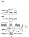
- a laser beam from a pulsed laser 813 such as a YAG laser is focused through a converging lens 814 onto the reflective layer 802, to form a nonreflective portion 815 as shown in step (6) in Figure 5. That is, a distinct waveform, such as the waveform (A) shown in step (7), is reproduced from the nonreflective portion 815 formed in step (6) in Figure 5.
- a marking detection signal such as shown by waveform (B) is obtained, from which hierarchial marking position information comprising an address, such as shown in signal (d), and an address, a frame synchronizing signal number, and a reproduced clock count, such as shown in signal (e), can be measured.
- a specific address (indicated by address n in Figure 5(d)) is read by the optical pickup from within the plurality of addresses shown in Figure 5(d).
- Figure 5(b) shows the physical location of the specific address in schematic form.
- Figure 5(e) shows the logical structure of the data. As shown in Figure 5(e), there are m frame synchronization signals under address n, and k reproduced clock pulses under each frame synchronization signal. Therefore, the position of the marking measured by the optical pickup can be represented by address, frame synchronization signal number, and reproduced clock count.
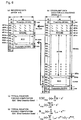
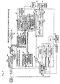
- Figure 7 is a block diagram showing a low reflectivity light amount detector 586 for detecting the nonreflective optical marking portion, along with its adjacent circuitry, in an optical disk manufacturing process.
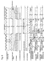
- Figure 8 is a diagram illustrating the principle of detecting address/clock positions of the low reflectivity portion.
- the following description deals with the operating principle when a read operation is performed on a nonreflective portion formed on an optical disk constructed from a single disk. It will be recognized that the same operating principle also applies to an optical disk constructed from two disks laminated together.
- the disk 800 is loaded into a marking reading apparatus equipped with a low reflectivity position detector 600 to read the marking, and in this case, since a signal waveform 823 due to the presence and absence of pits and a signal waveform 824 due to the presence of the nonreflective portion 584 are significantly different in signal level, they can be clearly distinguished using a simple circuit.
- the anti-piracy mark may be formed by changing the shape of pits on the master disk. This method will be described below.
- the barcode may be formed by changing the shape of pits on the master disk.
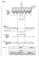
- Figure 8(1) shows a cross-sectional view of the optical disk.
- a comparator 587 in the low reflectivity light amount detector 586 detects the low reflectivity light portion by detecting an analog light reproduced signal having a lower signal level than a light amount reference value 588. During the detection period, a low reflectivity portion detection signal of the waveform shown in Figure 8(5) is output. The addresses and clock positions of the start position and end position of this signal are measured.
- the reproduced light signal is waveshaped by a waveform shaping circuit 590 having an AGC 590a, for conversion into a digital signal.
- a clock regenerator 38a regenerates a clock signal from the waveshaped signal.
- An EFM demodulator 592 in a demodulating section 591 demodulates the signal, and an ECC corrects errors and outputs a digital signal.
- the EFM-demodulated signal is also fed to a physical address output section 593 where an address of MSF, from Q bits of a subcode in the case of a CD, is output from an address output section 594 and a synchronizing signal, such as a frame synchronizing signal, is output from a synchronizing signal output section 595. From the clock regenerator 38a, a demodulated clock is output.
- a low reflectivity portion start/end position detector 599 accurately measures the start posistion and end position of the low reflectivity portion 584 by using an (n-1) address output section 597 and an address signal as well as a clock counter 598 and a synchronizing clock signal or the demodulated clock. This method will be described in detail by using the waveform diagrams shown in Figure 8. As shown in the cross-sectional view of the optical disk in Figure 8(1), the low reflectivity portion 584 of mark number 1 is formed partially. A reflection selope signal such as shown in Figure 8(3), is output, the signal level from the reflective portion being lower than the light amount reference value 588.
- the demodulated clock or synchronizing clock shown in Figure 8(6) is used along with address information.
- a reference clock 605 at address n in Figure 8(7) is measured.
- the address immediately preceding the address n is detected by the (n-1) address output section 597, it is found that the next sync 604 is a sync at address n.
- the number of clocks from the synch 604 to the reference clock 605, which is the start position of the low reflectivity light detection signal, is counted by the clock counter 598. This clock count is defined as a reference delay time TD which is measured by a reference delay time TD measuring section 608 for storage therein.
- the circuit delay time varies with reproduction apparatus used for reading, which means that the reference delay time TD varies depending on the reproduction apparatus used. Therefore, using the TD, a time delay corrector 607 applies time correction, and the resulting effect is that the start clock count for the low reflectivity portion can be measured accurately if reproduction apparatus of different designs are used for reading.
- the effect of this method is that the positions can be checked after compensating for variations of the reference delay time TD by using a simpler constitution.
- the position information read is first converted into ciphertext or "signed" with a digital signature. Then, the marking position information thus encrypted or signed is converted into a barcode as an ID unique to the optical disk, and the barcode is recorded in overwriting fashion in a prescribed region of a pre-pit area on the optical disk.
- Barcode patterns 584c - 584e in Figure 2(a) indicate the barcode written to the prescribed region of the pre-pit area, that is, in the innermost portion of the pre-pit area.
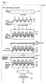
- Parts (1) to (5) of Figure 3 show the process from the recording of the barcode to the demodulation of the barcode detection signal by a PE-RZ modulated signal demodulator.
- the reflective layer is trimmed by a pulsed laser, and a barcode-like trimming pattern, such as shown in part (2) of the figure, is formed.
- a barcode-like trimming pattern such as shown in part (2) of the figure.
- an envelope waveform some portions of which are missing, as shown in part (3) of the figure, is obtained.
- the missing portions result in the generation of a low level signal that cannot occur with a signal generated from an ordinary pit. Therefore, this signal is sliced by a second slice level comparator to obtain a low-reflectivity portion detection signal as shown in part (4) of the figure.
- the playback signal of the barcode is demodulated from this low-reflectivity portion detection signal by the PE-RZ modulated signal demodulator 621 which will be described in detail in the second-half part (II).
- the PE-RZ modulated signal demodulator 621 instead of the PE-RZ modulated signal demodulator 621, a pulse-width modulated signal demodulator (PWM demodulator) may be used, in which case also, a similar effect can be obtained.
- PWM demodulator pulse-width modulated signal demodulator
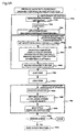
- FIGS. 9A and 9B show an encryption process using an RSA function.
- step 735a marking position information is measured at the optical disk maker
- step 695 where the position information is encrypted (or a digital signature is appended)
- step 698 where the position information is decrypted (or the signature is verified or authenticated) in the reproduction apparatus
- step 735w where a check is made to determine whether the disk is a legitimate optical disk or not.
- step 735a the marking position information on the optical disk is measured in step 735b.
- the position information is then compressed in step 735d, and the compressed position information H is obtained in step 735e.
- step 695 the ciphertext of the compressed position information H is constructed.
- a secret key, d, of 512 or 1024 bits, and secret keys, p and q, of 256 or 512 bits, are set, and in step 695b, encryption is performed using an RSA function.
- M is raised to d-th power and mod n is calculated to yield ciphertext C.
- step 695d the ciphertext C is recorded on the optical disk. The optical disk is thus completed and is shipped (step 735k).
- the optical disk is loaded in step 735m, and the ciphertext C is decrypted in step 698. More specifically, the ciphertext C is recovered in step 698e, and public keys, e and n, are set in step 698f; then in step b, to decrypt the ciphertext C, the ciphertext C is raised to e-th power and the mod n of the result is calculated to obtain plaintext M.
- the plaintext M is the compressed position information H.
- An error check may be performed in step 698g. If no errors, it is decided that no alterations have been made to the position information, and the process proceeds to the disk check routine 735w shown in Figure 9B. If an error is detected, it is decided that the data is not legitimate one, and the operation is stopped.
- step 736a the compressed position information H is expanded to recover the original position information.
- step 736c measurements are made to check whether the marking is actually located in the position on the optical disk indicated by the position information.
- step 736d it is checked whether the difference between the decrypted position information and the actually measured position information falls within a tolerance. If the check is OK in step 736e, the process proceeds to step 736h to output software or data or execute programs stored on the optical disk. If the check result is outside the tolerance, that is, if the two pieces of position information do not agree, a display is produced to the effect that the optical disk is an illegally duplicated one, and the operation is stopped in step 736g.
- RSA has the effect of reducing required capacity since only the ciphertext need be recorded.
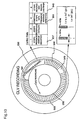
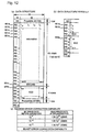
- CLV In the case of a DVD disk in the present embodiment, all data are recorded in pits with CLV, as shown in Figure 10. Stripes 923 (forming a barcode) are recorded with CAV.
- CLV recording means recording with constant linear velocity
- CAV recording means recording with constant angular velocity.
- the stripes 923 are recorded with CAV, superimposed on a pre-pit signal in a lead-in data area holding an address which is recorded with CLV. That is, the data is overwritten with the stripes.
- the pre-pit signal area maps into all the data areas where pits are formed.
- the prescribed region of the pre-pit signal area corresponds to an inner portion of the optical disk; this region is also called a post-cutting area (PCA).
- PCA post-cutting area
- the barcode is recorded with CAV, superimposed on pre-bit signals.
- the CLV data is recorded with a pit pattern from the master disk, while the CAV data is recorded with laser-removed portions of the reflective film.
- the barcode data Since the barcode data is written in overwriting fashion, pits are recorded between the barcode stripes 1T, 2T, and 3T. Using this pit information, optical head tracking is accomplished, and Tmax or Tmin of the pit information can be detected; therefore, motor rotational speed is controlled by detecting this signal.
- Tmin the relation between the trimming width t of stripe 923a and the pit clock T (pit) should be t > 14T (pit), as shown in Figure 10, to achieve the above effect. If t is shorter than 14T, the pulse width of the signal from the stripe 923a becomes equal to the pulse width of the pit signal, and discrimination between them is not possible, so that the signal from the stripe 923a cannot be demodulated.
- an address area 944 is provided longer than a unit of one address of pit information, address information can thus be obtained, making it possible to jump to the desired track.
- the ratio of the stripe area to the non-stripe area is made less than 50%, i.e., T(S) ⁇ T(NS); since the effective reflectivity decreases only by 6 dB, this has the effect of ensuring stable focusing of the optical head.
- the strips 923 which are CAV data, can be read by the optical pickup by applying rotational control using a rotational pulse from a Hall element, etc. in the motor 17.
- Figure 11 shows a flowchart illustrating a procedure for operations in a playback apparatus when pit data in the optical tracks in the stripe area cannot be correctly played back.
- step 930c rotational speed control is applied by using a rotational sensor of a Hall element in the motor or by measuring the T(max) or T(min) or frequency of a pit signal. If it is determined in step 930i that there are no stripes, the process jumps to step 930f. If there are stripes, the barcode is played back in step 930d, and when playback of the barcode is completed in step 930e, the optical head is moved in step 930f to an outer area where no stripes are recorded. In this area, since no stripes are recorded, the pits are played back correctly and accurate focus and tracking servo are achieved. Since the pit signal can be played back, usual rotation phase control can be performed to rotate the disk with CLV. As a result, in step 930h, the pit signal is played back correctly.
- switching means measures the radius position of the optical head from the optical head stopper or from the address of a pit signal, and based on the result of the measurement, correctly performs switching between the two rotation control modes.
- the control data recorded in the control data area 936 of the optical disk contains a PCA stripe presence/absence identifier 937 recorded as a pit signal. Therefore, the optical head is first moved, in step 940n, to an outer area where the control data is recorded. And then the optical head moves inwardly jumping across a plurality of tracks until reaching the control data area 936. And then in step 940a, the control data is played back. It can thus be checked whether the stripes are recorded or not. If, in step 940b, the stripe presence/absence identifier is 0, the process proceeds to step 940f to initiate rotation phase control for normal playback with CLV.
- step 940b the presence/absence identifier 937 is 1
- step 940h the presence or absence of a reverse-side record identifier 948 which indicates that the stripes are recorded on the side opposite from the side being played back, that is, on the reverse side. If the stripes are recorded on the reverse side, the process proceeds to step 940i to play back the recording surface on the reverse side of the optical disk. If the reverse side cannot be automatically played back, an indication is output for display, to urge the user to turn over the disk.
- step 940h If it is determined in step 940h that the stripes are recorded on the side being played back, the process proceeds to step 940c, where the head is moved to the stripe area 923 in the inner portion of the disk, and in step 940d, the control mode is switched to rotational speed control to play back the stripes 923 with CAV rotation. If the playback is completed in step 940e, then in step 940f the control mode is switched back to rotation phase control for CLV playback and the optical head is moved to the outer portion of the disk to play back pit signal data.
- the second method Since the stripe presence/absence identifier 937 is recorded in the pit area holding the control data, etc., as described above, the second method has the effect of being able to play back the stripes more reliably and more quickly compared to the first playback method described with reference to Figure 11.
- the stripe reverse-side record identifier 948 makes it possible to identify that the stripes are recorded on the reverse side of the disk; the effect is that the barcode stripes can be played back reliably in the case of a double-sided DVD optical disk.
- the stripe pattern can also be read from the reverse side of the disk.
- the stripes can be played back from the reverse side of the disk by checking the stripe reverse-side identifier 948 and by playing back the code in the reverse direction when reading the stripes.
- the present invention uses a bit string "01000110" as the synchronization code.
- the synchronization code is played back as "01100010", from which it can be detected that the barcode is being played back from the reverse side.
- the barcode recorded in penetrating fashion can be correctly played back even if played back from the reverse side of a double-sided disk.
- the playback apparatus of Figure 7 will be described in more detail later.
- a 300- ⁇ m wide guard-band area 999 where only address information is recorded but no other data is recorded, is provided between the PCA area 998 and the control data area 936, access to the control data can be made more stable.
- the guard-band area 999 will be described in more detail below.
- the optical head accesses the control data from the outer portion of the disk, the optical head moves inwardly jumping across a plurality of tracks until reaching the control data area 936. In some cases, the optical head may be moved past the destination control data area 936, landing at a portion further inward of the control data area. At this time, if the PCA area 998 exists directly adjacent to the inner circumference of the control data area, the optical head will lose its own position since an address cannot be played back in the PCA area 998. It, then, becomes impossible to control the optical head.
- the guard-band area with a width, for example, 300 ⁇ m, greater than one jump width of the optical head is provided in the above-noted portion, if the optical head is moved past the control data area 936 the optical head will always land within the guard-band area. Then, by reading an address in the guard-band area, the optical head knows its own position and can thus be repositioned on the destination control data area. In this way, the optical head can be controlled more reliably and more quickly.
- control data also contains an additional stripe data presence/absence identifier and a stripe recording capacity. That is, after recording first stripes on an optical disk, additional stripes can be recorded in an empty, unrecorded portion of the area.
- the first recorded stripes will be referred to as the first set of stripes, and the additionally recorded stripes as the second set of stripes.
- the control data provides an indication of how much space is available for additional recording; this prevents the possibility of destroying the first set of stripes by recording more than 360° over the area.
- a gap 949 longer than one pit-signal frame length is provided between the first set of stripes 923 and the second set of stripes 938; this serves to prevent the previously recorded trimming data from being destroyed.
- FIG. 7 is a block diagram of the playback apparatus already described above.
- the apparatus of Figure 7 will be described as a barcode reading apparatus, that is, a playback apparatus.
- Digital data is demodulated by the PE-RZ demodulator 942 in the above manner.
- the data is then fed to an ECC decoder 928 for error correction. That is, deinterleaving is performed in a deinterleaver 928a, and Reed-Solomon code computation is performed in an RS decoder 928b for error correction.
- Figure 12(a) shows the data structure after the barcode is ECC encoded according to the present embodiment.
- Figure 12(c) shows an ECC error-correction capability according to the present embodiment.
- the interleaving and Reed-Solomon error-correction coding shown in the data structure of Figure 12(a) are performed using the ECC encoder 927 shown in Figure 1 when recording stripes on an optical disk.
- the same sync code is assigned to four rows, reducing the number of sync codes by a factor of 4 and thus increasing efficiency.
- the scalability of the data structure will be described.
- Figure 6(a) is a diagram showing Figure 12(b) in further detail.
- the data row 951 constitutes EDC of 4B.
- Figure 6(b) shows this in an equivalent form. Error-correction encoding computation is performed, assuming that data rows from 951e to 951z all contain 0s.
- Mathematical equations for EDC and ECC computations are shown in Figures 6(c) and 6(d), respectively.
- the data is ECC-encoded by the ECC encoder 927 in the recording apparatus of Figure 1 and recorded as a barcode on the disk.
- the computation is performed assuming all remaining bits are 0s, so that the data is stored with a small recording capacity. This serves to shorten the productive tact.
- the above-described scalability has a significant meaning. More specifically, when performing laser trimming at a factory, it is important to shorten the productive tact. With a slow-speed apparatus which trims one stripe at a time, it will take more than 10 seconds to record a few thousand stripes to the full capacity. The time required for disk production is 4 seconds per disk; if full-capacity recording has to be done, the productive tact increases. On the other hand, for the moment, disk ID number will be a main application area of the present invention; in this application, the PCA area capacity can be as low as 10B. If 271B are recorded when only 10B need to be written, the laser processing time will increase by a factor of 6, leading to a production cost increase. The scalability method of the present invention achieves reductions in production cost and time.
- the ECC decoder 928 performs the EDC and ECC error-correction computations shown in Figures 6(c) and 6(d), assuming that the data rows 951e to 951z all contain 0s as shown in Figure 6(b); the effect of this is that data of 12 to 271B can be corrected for errors by using the same program. In this case, the number of program steps decreases, permitting the use of a small-capacity ROM in the microcomputer.
- the pulse width reproduced from each stripe width is made less than 1/2 of one pulse period. Since there are three difference pulse spacings, 1T, 2T, and 3T, the ratio of the sum of all the stripe areas in one track to the total area of the track is less than 1/3. With this arrangement, in the case of a disk of standard reflectivity of 70% the reflectivity of the stripe area is 2/3 of that, i.e., about 50%. Since this value is enough for focus control, the PCA area can be played back on a conventional ROM disk player.
Landscapes
- Engineering & Computer Science (AREA)
- Computer Security & Cryptography (AREA)
- Signal Processing (AREA)
- Physics & Mathematics (AREA)
- General Physics & Mathematics (AREA)
- Theoretical Computer Science (AREA)
- Manufacturing & Machinery (AREA)
- General Engineering & Computer Science (AREA)
- Optical Recording Or Reproduction (AREA)
- Optical Record Carriers And Manufacture Thereof (AREA)
- Signal Processing For Digital Recording And Reproducing (AREA)
- Manufacturing Optical Record Carriers (AREA)
Description
- The present invention relates to an optical disk, and an disk reproduction apparatus.
- In the manufacturing process of optical disks, it has been commonly practiced to record a serial number, lot number, etc. on each optical disk in the form of a barcode.
- Since such information cannot be written to a pit information area of the optical disk, it has been practiced to write the barcoded information to a non-information area, or unused space, on the optical disk.
- When reproducing (playing back) such an optical disk, the pit information is read by an optical pickup; to read the barcoded information such as a serial number, etc. recorded in the non-information area, however, a separate reading device has been used.
- In the above prior art optical disk, since information carrying a serial number and the like is not recorded in a pit area but recorded in a non-information area, as described above, a separate reading device has had to be provided in addition to the usual optical pickup, the resulting problem being increased complexity of the playback apparatus construction.
-
EP 0 549 488 A1 discloses an optical disk as described by the preamble part ofclaim 1. - In view of the above problem with the prior art, it is the object of the present invention to provide an optical disk which allows to read barcode like marks and main information recorded on the disk by a single optical pickup.
- It is another object of the invention to provide a corresponding optical disk reproduction apparatus for such an optical disk.
- These objects are achieved by the features of
claim 1 andclaim 5, respectively. Preferred embodiments thereof are subject matter of the dependent claims. -
- Figure 1 is a diagram showing a disk manufacturing process and a secondary recording process;
- Figure 2(a) is a top plan view of a disk, (b) is a top plan view of the disk, (c) is a top plan view of the disk, (d) is a transverse sectional view of the disk, and (e) is a waveform diagram of a reproduced signal;
- Figure 3 is a flowchart illustrating a process of recording encrypted position information on a disk in the form of a barcode;
- Figure 4 is a diagram showing a disk fabrication process and a secondary recording process (part 1);
- Figure 5 is a diagram showing the disk fabrication process and the secondary recording process (part 2);
- Figure 6(a) is a diagram showing part (b) of Figure 12 in further detail, (b) is a diagram showing an equivalent data structure for ECC encoding/decoding, (c) is a diagram showing a mathematical equation for EDC computation, and (d) is a diagram showing a mathematical equation for ECC computation;
- Figure 7 is a block diagram of a low-reflectivity position detector;
- Figure 8 is a diagram illustrating the principle of detecting address/clock positions of a low-reflectivity portion;
- Figure 9A is a flowchart illustrating a procedure for encryption, etc. using an RSA function;
- Figure 9B is a flowchart illustrating a position information check process;
- Figure 10 is a diagram showing the arrangement of stripes on a disk and the contents of control dada according to the embodiment;
- Figure 11 is a flowchart illustrating how control mode is switched between CAV and CLV when playing back stripes according to the embodiment;
- Figure 12(a) is a diagram showing a data structure after ECC encoding, (b) is a diagram showing a data structure after ECC encoding when n = 1), and (c) is a diagram showing an ECC error-correction capability;
-
- The preferred embodiments of the present invention will be described below with reference to the accompanying drawings. In the description hereinafter given, position information for piracy prevention, which is a form of ID, is taken as an example of information to be barcoded.
- We will first describe a general process flow from disk manufacturing to the completion of an optical disk by using the flowchart of Figure 1.
- In this patent specification, laser trimming is also referred to as laser marking, while a nonreflective optical marking portion is simply referred to as the barcode, stripe, marking, or optical marking or, sometimes, as the physical ID unique to a disk.
- First, the software company performs software authoring in
software production process 820. The completed software is delivered from the software company to the disk manufacturing factory. Indisk manufacturing process 816 at the disk manufacturing factory, the completed software is input instep 818a, a master disk is produced (step 818b), disks are pressed (steps steps 818f, 818h), the two disks are laminated together (step 818i), and a ROM disk such as a DVD or CD is completed (step 818m, etc.). - The thus completed
disk 800 is delivered to the software maker or to a factory under control of the software maker, where, insecondary recording process 817, an anti-piracy marking 584, such the one shown in Figure 2, is formed (step 819a), and accurate position information of this mark is read by a measuring means (step 819b) to obtain the position information which serves as the physical feature information of the disk. This physical feature information of the disk is encrypted instep 819c. The encrypted information is converted to a PE-RZ-modulated signal which is then recorded instep 819d as a barcode signal on the disk by using a laser. The disk physical feature information may be combined together with software feature information for encryption instep 819c. - The above processes will be described in further detail. That is, a disk fabrication process, a marking formation process, a marking position reading process, and an encrypted information writing process for an optical disk according to the present invention will be described in detail with reference to Figures 4 and 5. In the following description, the marking formation process and the marking position reading process are collectively called the secondary recording process.
- First, the disk fabrication process will be described. In the
disk fabrication process 806 shown in Figure 4, first atransparent substrate 801 is pressed in step (1). In step (2), a metal such as aluminum or gold is sputtered to form areflective layer 802. Anadhesive layer 804 formed from an ultraviolet curing resin is applied by spin coating to asubstrate 803 formed in a different processing step, and thesubstrate 803 is bonded to thetransparent substrate 801 having thereflective layer 802, and they are rotated at high speed to make the bonding spacing uniform. By exposure to external ultraviolet radiation, the resin hardens, thus firmly bonding the two substrates together. In step (4), a printedlayer 805 where a CD or DVD title is printed, is printed by screen printing or offset printing. Thus, in step (4), the ordinary laminated-type optical ROM disk is completed. - Next, the marking formation process will be described with reference to Figures 4 and 5. In Figure 4, a laser beam from a
pulsed laser 813 such as a YAG laser is focused through a converginglens 814 onto thereflective layer 802, to form anonreflective portion 815 as shown in step (6) in Figure 5. That is, a distinct waveform, such as the waveform (A) shown in step (7), is reproduced from thenonreflective portion 815 formed in step (6) in Figure 5. By slicing this waveform, a marking detection signal such as shown by waveform (B) is obtained, from which hierarchial marking position information comprising an address, such as shown in signal (d), and an address, a frame synchronizing signal number, and a reproduced clock count, such as shown in signal (e), can be measured. - At the rising edge of the thus obtained marking detection signal, a specific address (indicated by address n in Figure 5(d)) is read by the optical pickup from within the plurality of addresses shown in Figure 5(d). Figure 5(b) shows the physical location of the specific address in schematic form. On the other hand, Figure 5(e) shows the logical structure of the data. As shown in Figure 5(e), there are m frame synchronization signals under address n, and k reproduced clock pulses under each frame synchronization signal. Therefore, the position of the marking measured by the optical pickup can be represented by address, frame synchronization signal number, and reproduced clock count.
- Next, the process of reading the position of the thus formed marking will be described.
- Figure 7 is a block diagram showing a low reflectivity
light amount detector 586 for detecting the nonreflective optical marking portion, along with its adjacent circuitry, in an optical disk manufacturing process. Figure 8 is a diagram illustrating the principle of detecting address/clock positions of the low reflectivity portion. For convenience of explanation, the following description deals with the operating principle when a read operation is performed on a nonreflective portion formed on an optical disk constructed from a single disk. It will be recognized that the same operating principle also applies to an optical disk constructed from two disks laminated together. - As shown in Figure 7, the
disk 800 is loaded into a marking reading apparatus equipped with a lowreflectivity position detector 600 to read the marking, and in this case, since a signal waveform 823 due to the presence and absence of pits and a signal waveform 824 due to the presence of thenonreflective portion 584 are significantly different in signal level, they can be clearly distinguished using a simple circuit. - By removing the reflective film by laser light, as described above, a waveform easily distinguishable from that of a pit signal is obtained. Rather than forming an anti-piracy identification mark by removing the reflective film by laser light, as described above, the anti-piracy mark may be formed by changing the shape of pits on the master disk. This method will be described below.
- By removing the reflective film by laser light, as described above, a waveform easily distinguishable from that of a pit signal is obtained. Rather than forming the barcode of the invention by removing the reflective film by laser light, as described above, the barcode may be formed by changing the shape of pits on the master disk.
- As shown in Figure 8(1), the start and end positions of the nonreflective portion 564 having the above waveform can be easily detected by the low reflectivity
light amount detector 586 shown in the block diagram of Figure 7. Using the reproduced clock signal as the reference signal, position information is obtained in a low reflectivity positioninformation output section 596. Figure 8(1) shows a cross-sectional view of the optical disk. - As shown in Figure 7, a
comparator 587 in the low reflectivitylight amount detector 586 detects the low reflectivity light portion by detecting an analog light reproduced signal having a lower signal level than a lightamount reference value 588. During the detection period, a low reflectivity portion detection signal of the waveform shown in Figure 8(5) is output. The addresses and clock positions of the start position and end position of this signal are measured. - The reproduced light signal is waveshaped by a
waveform shaping circuit 590 having anAGC 590a, for conversion into a digital signal. Aclock regenerator 38a regenerates a clock signal from the waveshaped signal. AnEFM demodulator 592 in ademodulating section 591 demodulates the signal, and an ECC corrects errors and outputs a digital signal. The EFM-demodulated signal is also fed to a physicaladdress output section 593 where an address of MSF, from Q bits of a subcode in the case of a CD, is output from anaddress output section 594 and a synchronizing signal, such as a frame synchronizing signal, is output from a synchronizingsignal output section 595. From theclock regenerator 38a, a demodulated clock is output. - In a low reflectivity portion address/clock signal position
signal output section 596, a low reflectivity portion start/end position detector 599 accurately measures the start posistion and end position of thelow reflectivity portion 584 by using an (n-1) address output section 597 and an address signal as well as aclock counter 598 and a synchronizing clock signal or the demodulated clock. This method will be described in detail by using the waveform diagrams shown in Figure 8. As shown in the cross-sectional view of the optical disk in Figure 8(1), thelow reflectivity portion 584 ofmark number 1 is formed partially. A reflection selope signal such as shown in Figure 8(3), is output, the signal level from the reflective portion being lower than the lightamount reference value 588. This is detected by thelight level comparator 587, and a low reflectivity light detection signal, such as shown in Figure 8(5), is output from the low reflectivitylight amount detector 586. As shown by a reproduced digital signal in Figure 8(4), no digital signal is output from the mark region since it does not have a reflective layer. - Next, to obtain the start and end positions of the low reflectivity light detection signal, the demodulated clock or synchronizing clock shown in Figure 8(6) is used along with address information. First, a
reference clock 605 at address n in Figure 8(7) is measured. When the address immediately preceding the address n is detected by the (n-1) address output section 597, it is found that thenext sync 604 is a sync at address n. The number of clocks from thesynch 604 to thereference clock 605, which is the start position of the low reflectivity light detection signal, is counted by theclock counter 598. This clock count is defined as a reference delay time TD which is measured by a reference delay timeTD measuring section 608 for storage therein. - The circuit delay time varies with reproduction apparatus used for reading, which means that the reference delay time TD varies depending on the reproduction apparatus used. Therefore, using the TD, a
time delay corrector 607 applies time correction, and the resulting effect is that the start clock count for the low reflectivity portion can be measured accurately if reproduction apparatus of different designs are used for reading. Next, by finding the clock count and the start and end addresses for the optical mark No. 1 in the next track, clock m+14 at address n+12 is obtained, as shown in Figure 8(8). Since TD = m + 2, the clock count is corrected to 12, but for convenience of explanation, n+14 is used. We will describe another method, which eliminates the effects of varying delay times without having to obtain the reference delay time TD in the reproduction apparatus used for reading. This method can check whether the disk is a legitimate disk or not by checking whether the positional relationship ofmark 1 at address n in Figure 8(8) relative to anothermark 2 matches or not. That is, TD is ignored as a variable, and the difference between the position, A1 = a1 + TD, ofmark 1 measured and the position, A2 = a2 + TD, ofmark 2 measured is obtained, which is given as A1 - A2 = a1 - a2. At the same time, it is checked whether this difference matches the difference, a1 - a2, between the position a1 of the decryptedmark 1 and the position information a2 of themark 2, thereby judging whether the disk is a legitimate disk or not. The effect of this method is that the positions can be checked after compensating for variations of the reference delay time TD by using a simpler constitution. - Next, the encrypted information writing process will be described. The position information read is first converted into ciphertext or "signed" with a digital signature. Then, the marking position information thus encrypted or signed is converted into a barcode as an ID unique to the optical disk, and the barcode is recorded in overwriting fashion in a prescribed region of a pre-pit area on the optical disk.
Barcode patterns 584c - 584e in Figure 2(a) indicate the barcode written to the prescribed region of the pre-pit area, that is, in the innermost portion of the pre-pit area. - Parts (1) to (5) of Figure 3 show the process from the recording of the barcode to the demodulation of the barcode detection signal by a PE-RZ modulated signal demodulator. In part (1) of Figure 3, the reflective layer is trimmed by a pulsed laser, and a barcode-like trimming pattern, such as shown in part (2) of the figure, is formed. At the playback apparatus (player), an envelope waveform some portions of which are missing, as shown in part (3) of the figure, is obtained. The missing portions result in the generation of a low level signal that cannot occur with a signal generated from an ordinary pit. Therefore, this signal is sliced by a second slice level comparator to obtain a low-reflectivity portion detection signal as shown in part (4) of the figure. In part (5) of the figure, the playback signal of the barcode is demodulated from this low-reflectivity portion detection signal by the PE-RZ modulated
signal demodulator 621 which will be described in detail in the second-half part (II). It will be appreciated that, instead of the PE-RZ modulatedsignal demodulator 621, a pulse-width modulated signal demodulator (PWM demodulator) may be used, in which case also, a similar effect can be obtained. - When applying the above encryption or digital signature, a secret key of a public key encryption function is used. As an example of the encryption, Figures 9A and 9B show an encryption process using an RSA function.
- As shown in Figure 9A, the process consists of the following major routines:
step 735a where marking position information is measured at the optical disk maker, step 695 where the position information is encrypted (or a digital signature is appended),step 698 where the position information is decrypted (or the signature is verified or authenticated) in the reproduction apparatus, andstep 735w where a check is made to determine whether the disk is a legitimate optical disk or not. - First, in
step 735a, the marking position information on the optical disk is measured instep 735b. The position information is then compressed instep 735d, and the compressed position information H is obtained in step 735e. - In
step 695, the ciphertext of the compressed position information H is constructed. First, instep 695, a secret key, d, of 512 or 1024 bits, and secret keys, p and q, of 256 or 512 bits, are set, and instep 695b, encryption is performed using an RSA function. When the position information H is denoted by M, M is raised to d-th power and mod n is calculated to yield ciphertext C. Instep 695d, the ciphertext C is recorded on the optical disk. The optical disk is thus completed and is shipped (step 735k). - In the reproduction apparatus, the optical disk is loaded in
step 735m, and the ciphertext C is decrypted instep 698. More specifically, the ciphertext C is recovered in step 698e, and public keys, e and n, are set instep 698f; then in step b, to decrypt the ciphertext C, the ciphertext C is raised to e-th power and the mod n of the result is calculated to obtain plaintext M. The plaintext M is the compressed position information H. An error check may be performed instep 698g. If no errors, it is decided that no alterations have been made to the position information, and the process proceeds to thedisk check routine 735w shown in Figure 9B. If an error is detected, it is decided that the data is not legitimate one, and the operation is stopped. - In the
next step 736a, the compressed position information H is expanded to recover the original position information. Instep 736c, measurements are made to check whether the marking is actually located in the position on the optical disk indicated by the position information. Instep 736d, it is checked whether the difference between the decrypted position information and the actually measured position information falls within a tolerance. If the check is OK instep 736e, the process proceeds to step 736h to output software or data or execute programs stored on the optical disk. If the check result is outside the tolerance, that is, if the two pieces of position information do not agree, a display is produced to the effect that the optical disk is an illegally duplicated one, and the operation is stopped instep 736g. RSA has the effect of reducing required capacity since only the ciphertext need be recorded. - In the case of a DVD disk in the present embodiment, all data are recorded in pits with CLV, as shown in Figure 10. Stripes 923 (forming a barcode) are recorded with CAV. CLV recording means recording with constant linear velocity, while CAV recording means recording with constant angular velocity.
- In the present invention, the
stripes 923 are recorded with CAV, superimposed on a pre-pit signal in a lead-in data area holding an address which is recorded with CLV. That is, the data is overwritten with the stripes. In the present invention, the pre-pit signal area maps into all the data areas where pits are formed. The prescribed region of the pre-pit signal area, as mentioned in the present invention, corresponds to an inner portion of the optical disk; this region is also called a post-cutting area (PCA). In this PCA area, the barcode is recorded with CAV, superimposed on pre-bit signals. In this way, the CLV data is recorded with a pit pattern from the master disk, while the CAV data is recorded with laser-removed portions of the reflective film. Since the barcode data is written in overwriting fashion, pits are recorded between the barcode stripes 1T, 2T, and 3T. Using this pit information, optical head tracking is accomplished, and Tmax or Tmin of the pit information can be detected; therefore, motor rotational speed is controlled by detecting this signal. To detect Tmin, the relation between the trimming width t ofstripe 923a and the pit clock T (pit) should be t > 14T (pit), as shown in Figure 10, to achieve the above effect. If t is shorter than 14T, the pulse width of the signal from thestripe 923a becomes equal to the pulse width of the pit signal, and discrimination between them is not possible, so that the signal from thestripe 923a cannot be demodulated. To enable pit address information to be read at the same radius position as the stripes, an address area 944 is provided longer than a unit of one address of pit information, address information can thus be obtained, making it possible to jump to the desired track. Furthermore, the ratio of the stripe area to the non-stripe area, that is, the duty ratio, is made less than 50%, i.e., T(S) < T(NS); since the effective reflectivity decreases only by 6 dB, this has the effect of ensuring stable focusing of the optical head. - Next, we will describe an example of a condition in which tracking control cannot be applied during playback (this condition is also referred to as the tracking OFF condition).
- Since the
stripes 923 are written over pits, interrupting pit signals and preventing correct playback of the pit data, tracking control may not be possible on some players. In such players, thestrips 923, which are CAV data, can be read by the optical pickup by applying rotational control using a rotational pulse from a Hall element, etc. in themotor 17. - Figure 11 shows a flowchart illustrating a procedure for operations in a playback apparatus when pit data in the optical tracks in the stripe area cannot be correctly played back.
- In Figure 11, when a disk is inserted in
step 930a, the optical head is moved by a prescribed distance to the inner portion instep 930b. The optical head is thus positioned on the area where thestripes 923 of Figure 10 are recorded. - Here, it is not possible to correctly playback data from all the pits recorded in the
stripe area 923. In this case, therefore, usual rotation phase control cannot be applied for the playback of the pit data recorded with CLV. - In
step 930c, rotational speed control is applied by using a rotational sensor of a Hall element in the motor or by measuring the T(max) or T(min) or frequency of a pit signal. If it is determined instep 930i that there are no stripes, the process jumps to step 930f. If there are stripes, the barcode is played back instep 930d, and when playback of the barcode is completed instep 930e, the optical head is moved instep 930f to an outer area where no stripes are recorded. In this area, since no stripes are recorded, the pits are played back correctly and accurate focus and tracking servo are achieved. Since the pit signal can be played back, usual rotation phase control can be performed to rotate the disk with CLV. As a result, instep 930h, the pit signal is played back correctly. - By switching between the two rotation control modes, i.e., the rotational speed control and the rotation phase control by pit signals, the effect is obtained that two different kinds of data, barcode stripe data and pit-recorded data, can be played back. Since the stripes are recorded in the innermost area, switching means measures the radius position of the optical head from the optical head stopper or from the address of a pit signal, and based on the result of the measurement, correctly performs switching between the two rotation control modes.
- In the present invention, as shown in Figure 10, the control data recorded in the
control data area 936 of the optical disk contains a PCA stripe presence/absence identifier 937 recorded as a pit signal. Therefore, the optical head is first moved, in step 940n, to an outer area where the control data is recorded. And then the optical head moves inwardly jumping across a plurality of tracks until reaching thecontrol data area 936. And then in step 940a, the control data is played back. It can thus be checked whether the stripes are recorded or not. If, in step 940b, the stripe presence/absence identifier is 0, the process proceeds to step 940f to initiate rotation phase control for normal playback with CLV. On the other hand, if, in step 940b, the presence/absence identifier 937 is 1, then the process proceeds to step 940h to check the presence or absence of a reverse-side record identifier 948 which indicates that the stripes are recorded on the side opposite from the side being played back, that is, on the reverse side. If the stripes are recorded on the reverse side, the process proceeds to step 940i to play back the recording surface on the reverse side of the optical disk. If the reverse side cannot be automatically played back, an indication is output for display, to urge the user to turn over the disk. If it is determined in step 940h that the stripes are recorded on the side being played back, the process proceeds to step 940c, where the head is moved to thestripe area 923 in the inner portion of the disk, and in step 940d, the control mode is switched to rotational speed control to play back thestripes 923 with CAV rotation. If the playback is completed in step 940e, then in step 940f the control mode is switched back to rotation phase control for CLV playback and the optical head is moved to the outer portion of the disk to play back pit signal data. - Since the stripe presence/
absence identifier 937 is recorded in the pit area holding the control data, etc., as described above, the second method has the effect of being able to play back the stripes more reliably and more quickly compared to the first playback method described with reference to Figure 11. - When the PCA area is with tracking OFF, level of the noise signal which is generated by the pits drops. PCA signal level remains unchanged if tracking is set OFF. Therefore, in the filtered waveform, the pit signal drops, making it easier to distinguish between the PCA signal and the pit signal. This has the effect of simplifying the circuitry and reducing the error rate.
- Furthermore, the provision of the stripe reverse-
side record identifier 948 makes it possible to identify that the stripes are recorded on the reverse side of the disk; the effect is that the barcode stripes can be played back reliably in the case of a double-sided DVD optical disk. According to the present invention, since the stripes are recorded penetrating through the reflective films on both sides of a disk, the stripe pattern can also be read from the reverse side of the disk. The stripes can be played back from the reverse side of the disk by checking the stripe reverse-side identifier 948 and by playing back the code in the reverse direction when reading the stripes. The present invention uses a bit string "01000110" as the synchronization code. When played back from the reverse side, the synchronization code is played back as "01100010", from which it can be detected that the barcode is being played back from the reverse side. In this case, by demodulating the code in reverse direction in thedemodulator 942 in the playback apparatus of Figure 15, the barcode recorded in penetrating fashion can be correctly played back even if played back from the reverse side of a double-sided disk. The playback apparatus of Figure 7 will be described in more detail later. - Further, if, as shown in Figure 10, a 300-µm wide guard-
band area 999, where only address information is recorded but no other data is recorded, is provided between thePCA area 998 and thecontrol data area 936, access to the control data can be made more stable. - The guard-
band area 999 will be described in more detail below. - When the optical head accesses the control data from the outer portion of the disk, the optical head moves inwardly jumping across a plurality of tracks until reaching the
control data area 936. In some cases, the optical head may be moved past the destinationcontrol data area 936, landing at a portion further inward of the control data area. At this time, if thePCA area 998 exists directly adjacent to the inner circumference of the control data area, the optical head will lose its own position since an address cannot be played back in thePCA area 998. It, then, becomes impossible to control the optical head. - Accordingly, when the guard-band area with a width, for example, 300 µm, greater than one jump width of the optical head, is provided in the above-noted portion, if the optical head is moved past the
control data area 936 the optical head will always land within the guard-band area. Then, by reading an address in the guard-band area, the optical head knows its own position and can thus be repositioned on the destination control data area. In this way, the optical head can be controlled more reliably and more quickly. - Further, as shown in Figure 10, the control data also contains an additional stripe data presence/absence identifier and a stripe recording capacity. That is, after recording first stripes on an optical disk, additional stripes can be recorded in an empty, unrecorded portion of the area. The first recorded stripes will be referred to as the first set of stripes, and the additionally recorded stripes as the second set of stripes. With this configuration, when the first set of
stripes 923 is already recorded by trimming, as shown in Figure 10, the capacity of the available space for trimming the second set ofstripes 938 can be calculated. Accordingly, when the recording apparatus performs trimming to record the second set of stripes, the control data provides an indication of how much space is available for additional recording; this prevents the possibility of destroying the first set of stripes by recording more than 360° over the area. Furthermore, as shown in Figure 10, agap 949 longer than one pit-signal frame length is provided between the first set ofstripes 923 and the second set ofstripes 938; this serves to prevent the previously recorded trimming data from being destroyed. - Next, referring to Figure 7, a brief description will be given of a playback apparatus for playing back the barcode recorded on an optical disk by the above method. The description will also touch on productivity increases.
- Figure 7 is a block diagram of the playback apparatus already described above.
- Hereinafter, the apparatus of Figure 7 will be described as a barcode reading apparatus, that is, a playback apparatus.
- An explanation will be given again referring to Figure 7, this time focusing on the demodulation operation. First, high-frequency components generated by pits are removed by a low-pass filter (LPF filter) 94 from a stripe signal output.
- In the case of a DVD, there is a possibility that a maximum 14T signal may be played back, where T = 0.13 µm. In this case, it has been confirmed by experiment, a stripe signal and a high-frequency component generated by a pit can be separated by using the second-order or third-order Chevihov low-pass filter. That is, the use of a second- or higher-order LPF has the effect of being able to separate a pit signal and a barcode signal, thus ensuring stable playback of a barcode.
- Referring to Figure 7, a further description will be given. Digital data is demodulated by the PE-
RZ demodulator 942 in the above manner. The data is then fed to anECC decoder 928 for error correction. That is, deinterleaving is performed in adeinterleaver 928a, and Reed-Solomon code computation is performed in anRS decoder 928b for error correction. - A brief description will now be given in relation to productive tact.
- Figure 12(a) shows the data structure after the barcode is ECC encoded according to the present embodiment. Figure 12(b) shows the data structure after ECC encoding when n = 1 according to the present embodiment. Figure 12(c) shows an ECC error-correction capability according to the present embodiment.
- In the present invention, the interleaving and Reed-Solomon error-correction coding shown in the data structure of Figure 12(a) are performed using the
ECC encoder 927 shown in Figure 1 when recording stripes on an optical disk. With this error-correction method, a read error occurs in only one disk out of 107 = 10 million optical disks under the condition of that Byte error rate of 10-4 occurs, as shown in Figure 12(c). In this data structure, to reduce the code data length the same sync code is assigned to four rows, reducing the number of sync codes by a factor of 4 and thus increasing efficiency. With further reference to Figure 12, the scalability of the data structure will be described. In the present invention, the recording capacity can be varied freely, for example, within a range of 12B (12 Byte) to 188B in increments of 16B. That is, n can be changed within a range of n=1 to n=12, as shown in Figure 12(c). - As shown in Figure 12(b) and Figure 6(a), for example, in the data structure when n=1, there are only four
data rows ECC rows ECC encoder 927 in the recording apparatus of Figure 1 and recorded as a barcode on the disk. When n=1, data of 12B is recorded over an angle of 51 degrees on the disk. Likewise, when n=2, data of 18B can be recorded; when n=12, data of 271B can be recorded over an angle of 336 degrees on the disk. In the present invention, by encoding and decoding the data using the EDC and ECC computation equations shown in Figures 6(c) and 6(d), when the data amount is smaller than 188B, the computation is performed assuming all remaining bits are 0s, so that the data is stored with a small recording capacity. This serves to shorten the productive tact. When performing laser trimming, as in the present invention, the above-described scalability has a significant meaning. More specifically, when performing laser trimming at a factory, it is important to shorten the productive tact. With a slow-speed apparatus which trims one stripe at a time, it will take more than 10 seconds to record a few thousand stripes to the full capacity. The time required for disk production is 4 seconds per disk; if full-capacity recording has to be done, the productive tact increases. On the other hand, for the moment, disk ID number will be a main application area of the present invention; in this application, the PCA area capacity can be as low as 10B. If 271B are recorded when only 10B need to be written, the laser processing time will increase by a factor of 6, leading to a production cost increase. The scalability method of the present invention achieves reductions in production cost and time. - In the playback apparatus shown in Figure 7, when n=1 as in Figure 12(b), for example, the
ECC decoder 928 performs the EDC and ECC error-correction computations shown in Figures 6(c) and 6(d), assuming that thedata rows 951e to 951z all contain 0s as shown in Figure 6(b); the effect of this is that data of 12 to 271B can be corrected for errors by using the same program. In this case, the number of program steps decreases, permitting the use of a small-capacity ROM in the microcomputer. - Furthermore, the pulse width reproduced from each stripe width is made less than 1/2 of one pulse period. Since there are three difference pulse spacings, 1T, 2T, and 3T, the ratio of the sum of all the stripe areas in one track to the total area of the track is less than 1/3. With this arrangement, in the case of a disk of standard reflectivity of 70% the reflectivity of the stripe area is 2/3 of that, i.e., about 50%. Since this value is enough for focus control, the PCA area can be played back on a conventional ROM disk player.
Claims (7)
- An optical disk comprising:characterised in thata first recording area where a main information is recorded,a second recording area where barcode-like marks (923) each of which has a strip-like configuration in a radial direction and which are disposed in a circumferential direction, are recorded as a sub information, said second recording area being formed in a circumferential direction and wherein there is a certain area (949) in a circumferential direction where barcode-like marks are not recorded within said second recording area,
said first recording area contains at least a lead-in area from which data recording starts, and a control data area (936) which represents physical property of the optical disk,
said second recording area is disposed at a radial position which lies closer to the disk centre than said control data area (936) of said first recording area, and said second recording area is overlapped with said lead-in area, and
said sub information is a PE-RZ modulated signal recorded on said second recording area as a barcode signal so that a width of said barcode-like marks (923a, 923b) is half or less than a period of said barcode-like marks (923). - The optical disk according to claim 1, characterised in that a time period (t) of the width of the barcode-like mark in a circumferential direction has the following relation t > 14T, provided that (T) indicates a period of channel clock of the main information.
- The optical disk according to claim 1 or 2, characterised in that an identifier (937) which indicates whether the barcode-like marks (923) are present or not within said second recording area, is provided in the control data area (936).
- The optical disk according to claim 1,2, or 3, characterised in that address information are recorded in said certain area (949), where no barcode-like marks are recorded.
- An optical reproducing apparatus comprising
a reproducing means arranged for reproducing the optical disk according to one of claims 1 to 4,
PE-RZ demodulation means (942) for demodulating said sub information recorded on said second recording area,
another demodulation means (591) for demodulating said main information by using other demodulating method than said PE-demodulation method
the optical reproduction apparatus being arranged to read said sub information and said main information with the same optical head. - The optical reproducing apparatus according to claim 5, characterised in that EFM-demodulating means (592) is used as the demodulation means for the main information.
- The optical reproducing apparatus according to claim 5 or 6, characterised in that when said certain area (949) where said barcode-like marks (923) are not recorded is reproduced, address information is read out.
Applications Claiming Priority (5)
| Application Number | Priority Date | Filing Date | Title |
|---|---|---|---|
| JP26124795 | 1995-10-09 | ||
| JP26124795 | 1995-10-09 | ||
| JP891096 | 1996-01-23 | ||
| JP891096 | 1996-01-23 | ||
| EP96915172A EP0807929B1 (en) | 1995-10-09 | 1996-05-15 | Optical disk provided with bar code |
Related Parent Applications (1)
| Application Number | Title | Priority Date | Filing Date |
|---|---|---|---|
| EP96915172A Division EP0807929B1 (en) | 1995-10-09 | 1996-05-15 | Optical disk provided with bar code |
Publications (2)
| Publication Number | Publication Date |
|---|---|
| EP1030297A1 EP1030297A1 (en) | 2000-08-23 |
| EP1030297B1 true EP1030297B1 (en) | 2002-10-16 |
Family
ID=26343534
Family Applications (15)
| Application Number | Title | Priority Date | Filing Date |
|---|---|---|---|
| EP02015195A Expired - Lifetime EP1251502B1 (en) | 1995-10-09 | 1996-05-15 | An optical disk with an optical barcode |
| EP00109899A Expired - Lifetime EP1028423B1 (en) | 1995-10-09 | 1996-05-15 | An optical barcode forming method for optical discs, a marking forming apparatus, and a method of manufacturing an optical disk |
| EP00112310A Expired - Lifetime EP1031974B1 (en) | 1995-10-09 | 1996-05-15 | An optical disk reproduction apparatus |
| EP00109898A Expired - Lifetime EP1028422B1 (en) | 1995-10-09 | 1996-05-15 | An optical disk, an optical disk reproduction apparatus |
| EP00110461A Expired - Lifetime EP1030297B1 (en) | 1995-10-09 | 1996-05-15 | An optical disk and an optical disk recording method |
| EP00105014A Expired - Lifetime EP1006516B1 (en) | 1995-10-09 | 1996-05-15 | An optical disk and an optical disk reproduction apparatus |
| EP00101775A Expired - Lifetime EP1005034B1 (en) | 1995-10-09 | 1996-05-15 | An optical disk carrying barcoded information |
| EP00106447A Expired - Lifetime EP1006517B1 (en) | 1995-10-09 | 1996-05-15 | An optical disk and an optical disk reproduction apparatus |
| EP96915172A Expired - Lifetime EP0807929B1 (en) | 1995-10-09 | 1996-05-15 | Optical disk provided with bar code |
| EP02015194A Expired - Lifetime EP1251501B1 (en) | 1995-10-09 | 1996-05-15 | An optical disk with an optical barcode and reproduction apparatus |
| EP00103257A Expired - Lifetime EP1003162B1 (en) | 1995-10-09 | 1996-05-15 | An optical disk and an optical disk reproduction apparatus |
| EP00101774A Expired - Lifetime EP1005033B1 (en) | 1995-10-09 | 1996-05-15 | An optical disk and an optical disk reproduction apparatus |
| EP04006711A Expired - Lifetime EP1465164B1 (en) | 1995-10-09 | 1996-05-15 | Reproduction circuit in an optical disk reproduction apparatus |
| EP00104818A Expired - Lifetime EP1005035B1 (en) | 1995-10-09 | 1996-05-15 | An optical disk and an optical disk reproduction apparatus |
| EP06002367A Expired - Lifetime EP1659580B1 (en) | 1995-10-09 | 1996-05-15 | Bar code information method for optical disc |
Family Applications Before (4)
| Application Number | Title | Priority Date | Filing Date |
|---|---|---|---|
| EP02015195A Expired - Lifetime EP1251502B1 (en) | 1995-10-09 | 1996-05-15 | An optical disk with an optical barcode |
| EP00109899A Expired - Lifetime EP1028423B1 (en) | 1995-10-09 | 1996-05-15 | An optical barcode forming method for optical discs, a marking forming apparatus, and a method of manufacturing an optical disk |
| EP00112310A Expired - Lifetime EP1031974B1 (en) | 1995-10-09 | 1996-05-15 | An optical disk reproduction apparatus |
| EP00109898A Expired - Lifetime EP1028422B1 (en) | 1995-10-09 | 1996-05-15 | An optical disk, an optical disk reproduction apparatus |
Family Applications After (10)
| Application Number | Title | Priority Date | Filing Date |
|---|---|---|---|
| EP00105014A Expired - Lifetime EP1006516B1 (en) | 1995-10-09 | 1996-05-15 | An optical disk and an optical disk reproduction apparatus |
| EP00101775A Expired - Lifetime EP1005034B1 (en) | 1995-10-09 | 1996-05-15 | An optical disk carrying barcoded information |
| EP00106447A Expired - Lifetime EP1006517B1 (en) | 1995-10-09 | 1996-05-15 | An optical disk and an optical disk reproduction apparatus |
| EP96915172A Expired - Lifetime EP0807929B1 (en) | 1995-10-09 | 1996-05-15 | Optical disk provided with bar code |
| EP02015194A Expired - Lifetime EP1251501B1 (en) | 1995-10-09 | 1996-05-15 | An optical disk with an optical barcode and reproduction apparatus |
| EP00103257A Expired - Lifetime EP1003162B1 (en) | 1995-10-09 | 1996-05-15 | An optical disk and an optical disk reproduction apparatus |
| EP00101774A Expired - Lifetime EP1005033B1 (en) | 1995-10-09 | 1996-05-15 | An optical disk and an optical disk reproduction apparatus |
| EP04006711A Expired - Lifetime EP1465164B1 (en) | 1995-10-09 | 1996-05-15 | Reproduction circuit in an optical disk reproduction apparatus |
| EP00104818A Expired - Lifetime EP1005035B1 (en) | 1995-10-09 | 1996-05-15 | An optical disk and an optical disk reproduction apparatus |
| EP06002367A Expired - Lifetime EP1659580B1 (en) | 1995-10-09 | 1996-05-15 | Bar code information method for optical disc |
Country Status (11)
| Country | Link |
|---|---|
| US (30) | US6052465A (en) |
| EP (15) | EP1251502B1 (en) |
| JP (7) | JP3959114B2 (en) |
| KR (2) | KR100354674B1 (en) |
| CN (4) | CN100342443C (en) |
| DE (14) | DE69610859T2 (en) |
| HK (3) | HK1025419A1 (en) |
| MX (1) | MX9704096A (en) |
| MY (1) | MY117673A (en) |
| SG (3) | SG83122A1 (en) |
| WO (1) | WO1997014146A1 (en) |
Families Citing this family (232)
| Publication number | Priority date | Publication date | Assignee | Title |
|---|---|---|---|---|
| US6408285B1 (en) | 1995-10-09 | 2002-06-18 | Matsushita Electric Industrial Co., Ltd. | Optical disk reading device using both a decipher key and disk identification information for decryption |
| US7191154B2 (en) * | 1995-10-09 | 2007-03-13 | Matsushita Electric Industrial Co., Ltd. | Apparatus for encrypting and recording received content information on a recording medium using both medium identification information and a cipher key for encryption |
| CN100342443C (en) | 1995-10-09 | 2007-10-10 | 松下电器产业株式会社 | Optical disk, an optical disk barcode forming method and an optical disk reproduction apparatus |
| CN100414612C (en) | 1995-10-09 | 2008-08-27 | 松下电器产业株式会社 | Optic disc |
| JPH10106146A (en) * | 1996-09-25 | 1998-04-24 | Victor Co Of Japan Ltd | Recording and reproducing method of disk and reproducing device |
| EP0971345B1 (en) * | 1996-12-19 | 2006-05-03 | Matsushita Electric Industrial Co., Ltd. | Optical disk and method for recording onto an optical disk |
| JP3111923B2 (en) * | 1997-04-10 | 2000-11-27 | 松下電器産業株式会社 | Method and apparatus for recording information on optical disc |
| EP1653463A1 (en) | 1997-05-13 | 2006-05-03 | Kabushiki Kaisha Toshiba | License information copying method and apparatus, license information moving method |
| US6060773A (en) * | 1997-05-15 | 2000-05-09 | Nippon Telegraph And Telephone Corporation | Semiconductor chip and method of manufacturing the same |
| WO1999013470A1 (en) * | 1997-09-11 | 1999-03-18 | Digipress | Optical disc comprising a marking in particular anti-chipping, and method for making same |
| NL1007123C2 (en) * | 1997-09-26 | 1999-03-29 | Od & Me Bv | Record carriers, method for checking such record carriers, methods for manufacturing such record carriers, and apparatus suitable for carrying out such methods. |
| KR100279522B1 (en) * | 1997-11-20 | 2001-03-02 | 니시무로 타이죠 | Copy protection device and information recording medium used in such a copy protection device |
| KR100403270B1 (en) * | 1997-12-29 | 2004-03-20 | 삼성전자주식회사 | Method and device for protecting copyright of digital recording medium, and the digital recording medium thereof |
| US6687826B1 (en) * | 1997-12-29 | 2004-02-03 | Sony Corporation | Optical disc and method of recording data into same |
| JP3818474B2 (en) * | 1998-03-10 | 2006-09-06 | 日本ビクター株式会社 | Disc-shaped recording medium playback device |
| US7497534B2 (en) * | 2000-03-21 | 2009-03-03 | Elesys, Inc. | Enhancing angular position information for a radial printing system |
| US6736475B2 (en) * | 2000-03-21 | 2004-05-18 | Elesys, Inc. | Method for providing angular position information for a radial printing system |
| IL124571A0 (en) | 1998-05-21 | 1998-12-06 | Miki Mullor | Method of restricting software operation within a licensed limitation |
| US7304937B1 (en) | 1998-06-16 | 2007-12-04 | Thomson Licensing | Identification of program information on a recording medium |
| DE69911161T2 (en) * | 1998-07-22 | 2004-04-08 | Matsushita Electric Industrial Co., Ltd., Kadoma | DIGITAL DATA RECORDING DEVICE AND PROCESS FOR COPYRIGHT PROTECTION AND FOR EASIER PLAYBACK OF ENCRYPTED DATA AND CALCULAR READABLE MEDIUM FOR PROGRAM RECORDING |
| JP3716902B2 (en) * | 1998-09-04 | 2005-11-16 | 株式会社ソニー・コンピュータエンタテインメント | Data transmission / reception system, data reception device, data transmission / reception method, data reception method, and recording medium |
| DE69925087T2 (en) | 1998-09-22 | 2006-02-02 | Matsushita Electric Industrial Co., Ltd., Kadoma | An optical disc, a method of reproducing additional data from an optical disc, an optical disc reproducing apparatus and an optical disc recording and reproducing apparatus |
| WO2000023990A1 (en) | 1998-10-21 | 2000-04-27 | Matsushita Electric Industrial Co., Ltd. | Optical information recording medium, and method and apparatus for recording and reproduction |
| PT1143989E (en) * | 1999-01-14 | 2007-03-30 | Amylin Pharmaceuticals Inc | Exendins for glucagon suppression |
| JP4524920B2 (en) * | 1999-02-08 | 2010-08-18 | ソニー株式会社 | Information recording apparatus, information reproducing apparatus, authentication processing apparatus, information recording method, information reproducing method, and authentication processing method |
| CN100358034C (en) * | 1999-04-28 | 2007-12-26 | 松下电器产业株式会社 | Optical disk, optical disk recording and reproducing apparatus, method for recording reproducing, and delecting data on optical disk, and information procesisng system |
| EP1054395B1 (en) * | 1999-05-17 | 2007-06-27 | Sony Corporation | Optical disc recording apparatus, optical disc recording methods, and optical discs |
| US6538961B2 (en) | 1999-05-18 | 2003-03-25 | Sony Corporation | Apparatus and method for recording an optical disc identification code |
| DE60006538T2 (en) * | 1999-05-21 | 2004-09-30 | Matsushita Electric Industrial Co., Ltd., Kadoma | Recordable optical disc |
| US6603731B2 (en) | 1999-05-21 | 2003-08-05 | Matsushita Electric Industrial Co., Ltd. | Recordable optical disk |
| US6822639B1 (en) * | 1999-05-25 | 2004-11-23 | Silverbrook Research Pty Ltd | System for data transfer |
| WO2000079525A1 (en) * | 1999-06-22 | 2000-12-28 | Matsushita Electric Industrial Co., Ltd. | Optical disk, optical disk device, and reproducing method for optical disk |
| US6580683B1 (en) * | 1999-06-23 | 2003-06-17 | Dataplay, Inc. | Optical recording medium having a master data area and a writeable data area |
| US6519213B1 (en) * | 1999-06-29 | 2003-02-11 | Oak Technology, Inc. | Method and apparatus for reading data from a disk |
| JP3292298B2 (en) * | 1999-07-14 | 2002-06-17 | ソニー株式会社 | Information recording apparatus, information recording method, information recording medium, information reproducing apparatus, and information reproducing method |
| WO2001006502A1 (en) | 1999-07-15 | 2001-01-25 | Matsushita Electric Industrial Co., Ltd. | Optical recording medium and method for recording optical recording medium |
| EP1385164A3 (en) * | 1999-08-25 | 2009-01-07 | Sony Corporation | Data outputting method and data outputting device |
| US7028011B1 (en) * | 1999-09-10 | 2006-04-11 | Eastman Kodak Company | Hybrid optical recording disc with copy protection |
| US6631359B1 (en) * | 1999-09-10 | 2003-10-07 | Dphi Acquisitions, Inc. | Writeable medium access control using a medium writeable area |
| US6661768B1 (en) | 1999-10-13 | 2003-12-09 | Matsushita Electric Industrial Co., Ltd. | Optical disk, and method and apparatus for reproducing information recorded in optical disk |
| TW561471B (en) * | 2000-01-07 | 2003-11-11 | Matsushita Electric Ind Co Ltd | Information recording disc and information reproducing system |
| KR100762559B1 (en) * | 2000-01-31 | 2007-10-01 | 엘지전자 주식회사 | Method and Apparatus for reproducing recording medium which comprised copyright |
| JP2001268510A (en) * | 2000-03-15 | 2001-09-28 | Sony Corp | Device and method for reproducing information and recording medium |
| US6754143B2 (en) * | 2000-03-24 | 2004-06-22 | Matsushita Electric Industrial Co., Ltd. | Optical information recording medium, and method and apparatus for recording/reproducing information thereon |
| US6532201B1 (en) * | 2000-04-03 | 2003-03-11 | Hewlett-Packard Company | Copy protection for optical discs |
| JP4310885B2 (en) * | 2000-05-11 | 2009-08-12 | ソニー株式会社 | Optical disc apparatus, optical disc access method, and optical disc |
| JP3895181B2 (en) * | 2000-05-19 | 2007-03-22 | 松下電器産業株式会社 | Data recording medium and reproducing apparatus thereof |
| JP4395998B2 (en) * | 2000-06-07 | 2010-01-13 | ソニー株式会社 | Optical disc apparatus, optical disc recording method, and optical disc |
| US6638593B2 (en) | 2000-06-30 | 2003-10-28 | Verification Technologies, Inc. | Copy-protected optical media and method of manufacture thereof |
| US20050063256A1 (en) * | 2000-06-30 | 2005-03-24 | Selinfreund Richard H. | Data storage in optical discs |
| WO2002002301A1 (en) | 2000-06-30 | 2002-01-10 | Verification Technologies Inc. | Copy-protected optical media and method of manufacture thereof |
| US7124944B2 (en) * | 2000-06-30 | 2006-10-24 | Verification Technologies, Inc. | Product packaging including digital data |
| US7660415B2 (en) * | 2000-08-03 | 2010-02-09 | Selinfreund Richard H | Method and apparatus for controlling access to storage media |
| JP4595182B2 (en) * | 2000-09-07 | 2010-12-08 | ソニー株式会社 | Information recording apparatus, information reproducing apparatus, information recording method, information reproducing method, information recording medium, and program providing medium |
| JP4348851B2 (en) | 2000-09-21 | 2009-10-21 | ソニー株式会社 | Recording medium, disk recording apparatus and method, and disk reproducing apparatus and method |
| EP1325497A2 (en) * | 2000-09-22 | 2003-07-09 | Matsushita Electric Industrial Co., Ltd. | Optical disc and a reproduction method, reproduction apparatus, and recording apparatus for the same |
| US7324647B1 (en) | 2000-10-23 | 2008-01-29 | Bbn Technologies Corp. | Quantum cryptographic key distribution networks with untrusted switches |
| US6769060B1 (en) * | 2000-10-25 | 2004-07-27 | Ericsson Inc. | Method of bilateral identity authentication |
| WO2002037483A1 (en) * | 2000-11-06 | 2002-05-10 | Matsushita Electric Industrial Co., Ltd. | Optical recording medium, optical recording medium production method, optical recording medium production apparatus, program, and medium |
| CN1486488A (en) * | 2000-11-07 | 2004-03-31 | 松下电器产业株式会社 | Optical disk, recording device for optical disk, reproducing device for optical disk, method of reproducing optical disk and method of producing optical disk |
| US6925048B2 (en) * | 2000-11-16 | 2005-08-02 | Matsushita Electric Industrial Co., Ltd. | Optical disc apparatus |
| JP2002163857A (en) * | 2000-11-22 | 2002-06-07 | Sharp Corp | Method of recording/reproducing information, information recording medium, information recording/ reproducing apparatus, and method for manufacturing information recording medium |
| EP1344212B1 (en) * | 2000-12-14 | 2008-08-13 | ECD Systems, Inc. | Method for determining authenticity of an optical recording medium and optical recording medium |
| AU780800B2 (en) * | 2000-12-19 | 2005-04-21 | Sony Corporation | Optical disc, recording apparatus and method for optical disc, and its reproducing method |
| JP3847557B2 (en) * | 2000-12-22 | 2006-11-22 | シャープ株式会社 | Playback device |
| US6908725B2 (en) * | 2001-01-16 | 2005-06-21 | Dphi Acquisitions, Inc. | Double-sided hybrid optical disk with surface topology |
| US7368222B2 (en) | 2001-01-16 | 2008-05-06 | Dphi Acquisitions, Inc. | Optical data storage media with enhanced contrast |
| JP2002319230A (en) * | 2001-01-25 | 2002-10-31 | Sony Computer Entertainment Inc | Recording medium, information processor, server, and method, program for contents distribution and recording medium thereof |
| US20020141583A1 (en) * | 2001-01-29 | 2002-10-03 | Eastman Kodak Company | Copy protection using a preformed ID and a unique ID on a programmable CD-ROM |
| JP4766502B2 (en) * | 2001-02-05 | 2011-09-07 | 独立行政法人産業技術総合研究所 | Multilayer pinhole disk and manufacturing method thereof |
| KR20020067853A (en) * | 2001-02-19 | 2002-08-24 | 주식회사 마크애니 | Apparatus and Method for controlling the copy and play of a digital audio contents using digital watermarking |
| US6582197B2 (en) | 2001-02-22 | 2003-06-24 | Simon E. Coulson | Method of investment casting with casting identification |
| JP2002313031A (en) * | 2001-04-12 | 2002-10-25 | Nec Corp | Optical disk having identification performance |
| US7092333B2 (en) | 2001-04-17 | 2006-08-15 | Matsushita Electric Industrial Co., Ltd. | Device and program for checking optical disks |
| US6966837B1 (en) | 2001-05-10 | 2005-11-22 | Best Robert M | Linked portable and video game systems |
| AU2002304151B2 (en) * | 2001-06-08 | 2007-08-23 | Sony Disc & Digital Solutions, Inc. | Optical disk medium, and data recording method and device |
| AU2007202951B2 (en) * | 2001-06-08 | 2010-12-16 | Sony Disc & Digital Solutions, Inc. | Optical disc medium, and data recording method and device |
| WO2003003358A1 (en) * | 2001-06-29 | 2003-01-09 | Sony Corporation | Data recording medium, recording medium recording and/reproducing apparatus, and recording or reproducing method |
| JP2003030856A (en) * | 2001-07-17 | 2003-01-31 | Pioneer Electronic Corp | Optical disk and recording/reproducing device |
| KR100788646B1 (en) * | 2001-08-09 | 2007-12-26 | 삼성전자주식회사 | An optical disk Burst Cutting Area code recording method |
| US7068790B1 (en) | 2001-08-31 | 2006-06-27 | Bbn Technologies Corp. | Systems and methods for path set-up in a quantum key distribution network |
| US7062045B2 (en) * | 2001-09-06 | 2006-06-13 | Clwt, Llc | Media protection system and method |
| US20030046568A1 (en) * | 2001-09-06 | 2003-03-06 | Riddick Christopher J. | Media protection system and method and hardware decryption module used therein |
| JP4880140B2 (en) | 2001-09-07 | 2012-02-22 | 任天堂株式会社 | Optical disc, optical disc playback device and recording device |
| US20040030909A1 (en) * | 2001-09-14 | 2004-02-12 | Yoichiro Sako | Recording medium reproduction method and reproduction apparatus, and recording medium recording method and recording apparatus |
| JP2003118173A (en) * | 2001-10-10 | 2003-04-23 | Nippon Bunka Seiko Kk | Method for imaging on optical disc by ink jet |
| EP1441343A4 (en) * | 2001-10-31 | 2008-07-16 | Sony Corp | Data recording method, recorder, and data reproducing method and device |
| US7139885B2 (en) * | 2001-12-27 | 2006-11-21 | Hitachi, Ltd. | Method and apparatus for managing storage based replication |
| TWI254292B (en) | 2002-01-25 | 2006-05-01 | Sony Corp | Information recording device and method, information reproducing device and method, recording medium and disc recording medium |
| TWI258135B (en) | 2002-01-25 | 2006-07-11 | Sony Corp | Information recording device and method, information reproducing device and method, recording medium, and disc recording medium |
| JP4256100B2 (en) * | 2002-01-31 | 2009-04-22 | 富士通株式会社 | Legitimate media management system |
| US7716485B2 (en) * | 2002-02-01 | 2010-05-11 | Sca Ipla Holdings Inc. | Systems and methods for media authentication |
| US20050084645A1 (en) * | 2002-02-07 | 2005-04-21 | Selinfreund Richard H. | Method and system for optical disc copy-protection |
| US6775839B1 (en) * | 2002-03-15 | 2004-08-10 | O'brien Patrick J. | Optical storage device with print layer surface feature |
| US7394738B2 (en) * | 2002-03-20 | 2008-07-01 | Hewlett-Packard Development Company, L.P. | Identifying optical disc properties from information read from label side of optical disc |
| US20040199780A1 (en) * | 2002-03-22 | 2004-10-07 | Heung-Chan Seung | Copy-protected optical recording medium, a method for driving therefor and a method of manufacturing thereof |
| US7016294B2 (en) * | 2002-03-25 | 2006-03-21 | Dphi Acquisitions, Inc. | Inner region identifier for optical disk |
| JP4195573B2 (en) * | 2002-04-03 | 2008-12-10 | Tdk株式会社 | Recording data recording method, recording data reproducing method, recording apparatus, reproducing apparatus, and multilayer optical recording medium |
| JP4132934B2 (en) * | 2002-04-12 | 2008-08-13 | 株式会社ソニー・ディスクアンドデジタルソリューションズ | Read-only optical recording medium and optical recording method |
| US20030193883A1 (en) * | 2002-04-15 | 2003-10-16 | Parks William S. | Methods of detecting counterfeit or authentic optical and/or audio discs |
| US7350081B1 (en) | 2002-04-29 | 2008-03-25 | Best Robert M | Secure execution of downloaded software |
| JP2004030860A (en) * | 2002-04-30 | 2004-01-29 | Pioneer Electronic Corp | Recording disk and apparatus and method for reproducing recorded information |
| TWI228249B (en) * | 2002-05-28 | 2005-02-21 | Tech Media Corp U | Optical record medium having a scratching-off layer |
| KR100915875B1 (en) * | 2002-06-05 | 2009-09-07 | 엘지전자 주식회사 | High density read only optical disc, and method for recording and reproducing an encoded data on them |
| JP2004087063A (en) | 2002-07-02 | 2004-03-18 | Sony Corp | Data recording medium, medium information recording method, medium information recording device, medium information reproducing method, medium information reproducing device, information service method, and information service system |
| EP1380982A1 (en) * | 2002-07-08 | 2004-01-14 | Sicpa Holding S.A. | Method and device for coding articles |
| DE10231687A1 (en) * | 2002-07-10 | 2004-01-22 | Robert Bosch Gmbh | Method and device for notifying the driver of a motor vehicle |
| JP2004047020A (en) * | 2002-07-15 | 2004-02-12 | Fuji Electric Holdings Co Ltd | Magnetic disk medium and fixed magnetic disk device |
| JP2004054978A (en) * | 2002-07-17 | 2004-02-19 | Fuji Electric Holdings Co Ltd | Magnetic recording medium provided with track id information, and magnetic recorder |
| US7457416B1 (en) | 2002-07-17 | 2008-11-25 | Bbn Technologies Corp. | Key distribution center for quantum cryptographic key distribution networks |
| MXPA04004284A (en) * | 2002-08-22 | 2004-11-29 | Lg Electronics Inc | High-density optical disc and recording/reproducing method thereof. |
| KR20040024007A (en) * | 2002-09-12 | 2004-03-20 | 엘지전자 주식회사 | High density read only optical disc |
| US20040052203A1 (en) * | 2002-09-13 | 2004-03-18 | Brollier Brian W. | Light enabled RFID in information disks |
| AU2003275315A1 (en) * | 2002-09-26 | 2004-04-19 | Verification Technologies, Inc. | Authentication of items using transient optical state change materials |
| US7627126B1 (en) | 2002-10-15 | 2009-12-01 | Bbn Technologies Corp. | Systems and methods for implementing path length control for quantum cryptographic systems |
| US7284126B2 (en) * | 2002-11-12 | 2007-10-16 | Agilent Technologies, Inc. | Device authentication using pre-configured security keys |
| US7236597B2 (en) | 2002-12-20 | 2007-06-26 | Bbn Technologies Corp. | Key transport in quantum cryptographic networks |
| US7460670B1 (en) | 2002-12-20 | 2008-12-02 | Bbn Technologies Corp. | Systems and methods for managing quantum cryptographic networks |
| US7036736B2 (en) | 2003-01-08 | 2006-05-02 | Hoss Sarbaz | Event entry and advertising medium |
| JP4468942B2 (en) | 2003-01-23 | 2010-05-26 | エルジー エレクトロニクス インコーポレイティド | Recording medium having selective information, apparatus and method for forming, recording and reproducing data on the recording medium, and apparatus and method for controlling reproduction |
| MXPA04012390A (en) | 2003-01-23 | 2005-02-25 | Lg Electronics Inc | Recording medium with copy protection information formed in intermittent or alternate wobbled pits and apparatus and methods for forming, recording, and reproducing the recording medium. |
| KR100952949B1 (en) | 2003-01-24 | 2010-04-15 | 엘지전자 주식회사 | Method for managing a copy protection information of high density optical disc |
| US20060203700A1 (en) * | 2003-02-06 | 2006-09-14 | Verification Technologies, Inc. | Method and system for optical disk copy-protection |
| EP1959448B1 (en) * | 2003-02-20 | 2013-04-10 | Koninklijke Philips Electronics N.V. | Information carrier comprising access information |
| KR100932506B1 (en) | 2003-02-27 | 2009-12-17 | 엘지전자 주식회사 | Regeneration control information management and data reproduction control method of high density optical disc |
| US20040172548A1 (en) * | 2003-03-01 | 2004-09-02 | Anderson Daryl E. | Access permission based on optically readable marking on optical disc label region |
| KR100524952B1 (en) * | 2003-03-07 | 2005-11-01 | 삼성전자주식회사 | Method for protecting data of recordable medium and disk drive using the same |
| US20040182933A1 (en) * | 2003-03-17 | 2004-09-23 | Kai-Yuan Tien | Light source structure without moving parts for a laser barcode scanner |
| US7706535B1 (en) | 2003-03-21 | 2010-04-27 | Bbn Technologies Corp. | Systems and methods for implementing routing protocols and algorithms for quantum cryptographic key transport |
| US7430295B1 (en) | 2003-03-21 | 2008-09-30 | Bbn Technologies Corp. | Simple untrusted network for quantum cryptography |
| JP2004326857A (en) * | 2003-04-22 | 2004-11-18 | Sony Corp | Magneto-optical disk and its recording and reproducing method |
| WO2004097826A1 (en) * | 2003-04-29 | 2004-11-11 | Koninklijke Philips Electronics N.V. | System for copy protection of an information carrier |
| EP1629473B1 (en) * | 2003-05-30 | 2010-06-30 | Doug Carson & Associates, Inc. | Improved multi-layer optical disc format |
| TW588847U (en) * | 2003-06-19 | 2004-05-21 | Yes Tek Corp | Structure of color digital audio-video disc |
| JP4556395B2 (en) * | 2003-08-28 | 2010-10-06 | ソニー株式会社 | Content identification method and content identification system |
| US7391691B2 (en) | 2003-08-29 | 2008-06-24 | General Electric Company | Method for facilitating copyright protection in digital media and digital media made thereby |
| WO2005029492A1 (en) * | 2003-09-18 | 2005-03-31 | Matsushita Electric Industrial Co., Ltd. | Recording/reproducing device and recording medium |
| JP2005093036A (en) * | 2003-09-19 | 2005-04-07 | Sanyo Electric Co Ltd | Recording medium and recording/reproduction device |
| JP3843975B2 (en) * | 2003-10-01 | 2006-11-08 | ソニー株式会社 | Recording medium management apparatus and recording medium management method |
| US7447317B2 (en) | 2003-10-02 | 2008-11-04 | Fraunhofer-Gesellschaft Zur Foerderung Der Angewandten Forschung E.V | Compatible multi-channel coding/decoding by weighting the downmix channel |
| EP1522996B1 (en) * | 2003-10-08 | 2011-03-30 | Panasonic Corporation | Method of recording identification information, equipment therefor and information recording medium |
| DE10351166A1 (en) * | 2003-11-03 | 2005-06-16 | Stefan Schreiber | Hybrid optical disc with modified CD layer |
| US7058378B2 (en) * | 2003-11-18 | 2006-06-06 | Interdigital Technology Corporation | Method and apparatus for automatic frequency correction of a local oscilator with an error signal derived from an angle value of the conjugate product and sum of block correlator outputs |
| US20050105457A1 (en) * | 2003-11-19 | 2005-05-19 | Cookson Christopher J. | Double-sided optical disc with means for indicating its proper direction of rotation |
| US8611195B2 (en) | 2003-11-21 | 2013-12-17 | Koninklijke Philips N.V. | Detection of data in burst cutting area of optical disk |
| KR101128371B1 (en) | 2003-11-21 | 2012-03-26 | 코닌클리케 필립스 일렉트로닉스 엔.브이. | Detection of data in burst cutting area of optical disk |
| US7596069B2 (en) * | 2003-11-25 | 2009-09-29 | Dell Products L.P. | Optical medium aligned information system and method |
| JP2005166096A (en) * | 2003-11-28 | 2005-06-23 | Toshiba Corp | Optical disk, optical disk device, optical disk recording and reproducing method, bca code recording device, and bca code recording method |
| US20050122887A1 (en) * | 2003-12-08 | 2005-06-09 | Shinya Abe | Optical information recording medium and method of recording bar code-like marks |
| US20050147379A1 (en) | 2003-12-24 | 2005-07-07 | Home Box Office, A Delaware Corporation | Personalization of mass-duplicated media |
| EP1555670A1 (en) * | 2004-01-14 | 2005-07-20 | Sgn | Method of preventing unauthorized duplication of an optical disc by authentification of a physical parameter, manufacturing process of such an optical disc and an optical disc thus obtained |
| JP3954583B2 (en) * | 2004-02-16 | 2007-08-08 | メモリーテック株式会社 | Optical disc, optical disc manufacturing apparatus and optical disc manufacturing method |
| US20050185548A1 (en) * | 2004-02-19 | 2005-08-25 | Weirauch Charles R. | Information access control for optical media |
| US7515716B1 (en) | 2004-02-26 | 2009-04-07 | Bbn Technologies Corp. | Systems and methods for reserving cryptographic key material |
| US7697693B1 (en) | 2004-03-09 | 2010-04-13 | Bbn Technologies Corp. | Quantum cryptography with multi-party randomness |
| US7330326B2 (en) * | 2004-03-09 | 2008-02-12 | Hewlett-Packard Development Company, L.P. | Recordable disk rotational speed error correction circuit |
| KR100745112B1 (en) * | 2004-04-22 | 2007-08-01 | 히다치 막셀 가부시키가이샤 | Optical disk recording method, and optical disk |
| US7289644B2 (en) * | 2004-04-27 | 2007-10-30 | Thomson Licensing | Anti-piracy coding of motion pictures |
| WO2005109433A1 (en) * | 2004-05-06 | 2005-11-17 | Koninklijke Philips Electronics N.V. | Spiral angle controlled information |
| WO2005111926A1 (en) * | 2004-05-18 | 2005-11-24 | Silverbrook Research Pty Ltd | Method and apparatus for security document tracking |
| EP1752972B1 (en) * | 2004-06-09 | 2010-08-04 | Panasonic Corporation | Optical disc apparatus and method |
| JP2006011682A (en) * | 2004-06-24 | 2006-01-12 | Sony Corp | Information recording medium verification device, information recording medium verification method and computer program |
| JP4439521B2 (en) * | 2004-07-05 | 2010-03-24 | パイオニア株式会社 | Information recording medium |
| US20060023598A1 (en) * | 2004-07-30 | 2006-02-02 | Babinski James P | Method and apparatus for protecting against copying of content recorded on optical recording media |
| US20060039554A1 (en) * | 2004-08-18 | 2006-02-23 | Roxio, Inc. | High security media encryption |
| DE102004046618A1 (en) * | 2004-09-25 | 2006-03-30 | Robert Bosch Gmbh | Circuit arrangement for analog / digital conversion |
| US20060072444A1 (en) * | 2004-09-29 | 2006-04-06 | Engel David B | Marked article and method of making the same |
| US7459259B2 (en) * | 2004-09-29 | 2008-12-02 | Sabic Innovative Plastics Ip B.V. | Marked article and method of making the same |
| JP4561299B2 (en) * | 2004-10-14 | 2010-10-13 | ソニー株式会社 | Replacement processing method, recording apparatus, and recording system |
| JP4225275B2 (en) | 2004-10-18 | 2009-02-18 | 日本ビクター株式会社 | Optical disc recording apparatus, recording method, recording program, and optical disc |
| JP2006127673A (en) * | 2004-10-29 | 2006-05-18 | Toshiba Corp | Information recording medium, information reproducing device, information reproducing method, and information recording method |
| JP2006155802A (en) * | 2004-11-30 | 2006-06-15 | Toshiba Corp | Information storage medium, stamper, management information recording apparatus, disk device, and management information reproducing method |
| US20060136746A1 (en) * | 2004-12-18 | 2006-06-22 | Al-Khateeb Osama O M | Security system for preventing unauthorized copying of digital data |
| JP4692003B2 (en) * | 2005-02-10 | 2011-06-01 | ソニー株式会社 | Information processing apparatus, information processing method, and computer program |
| JP2006260614A (en) * | 2005-03-15 | 2006-09-28 | Sony Corp | Disk manufacturing method, data recorder, information recording medium, information processor and method for processing information, and computer program |
| US20090046553A1 (en) * | 2005-03-30 | 2009-02-19 | Zdenek Varga | Protection of disk data carriers against making illegal copies |
| JP4473768B2 (en) * | 2005-04-14 | 2010-06-02 | 株式会社東芝 | Information storage medium, reproducing method and recording method |
| WO2006125269A1 (en) * | 2005-05-25 | 2006-11-30 | Romeena Pty Limited As Trustee For Kemp Family Trust | Instrument tracking |
| US7664266B2 (en) * | 2005-05-27 | 2010-02-16 | Microsoft Corporation | Compression of fiber-based certificate of authenticity data |
| US20060274617A1 (en) * | 2005-06-03 | 2006-12-07 | Musto James J | Techniques for forming burst cutting area mark |
| JP2007026635A (en) * | 2005-06-17 | 2007-02-01 | Hitachi Maxell Ltd | Information recording medium |
| TWI270928B (en) * | 2005-07-22 | 2007-01-11 | Sino American Silicon Products | Method of manufacturing composite wafer sructure |
| CN101243513A (en) | 2005-08-23 | 2008-08-13 | 皇家飞利浦电子股份有限公司 | Information carrier authentication with a physical one-way function |
| US8031582B2 (en) | 2005-09-30 | 2011-10-04 | Nec Corporation | Optical information recording medium, BCA information recorder, and BCA information recording method |
| CN101000785B (en) * | 2006-01-13 | 2010-05-12 | 鸿富锦精密工业(深圳)有限公司 | Disc kind recognition method and system |
| US8786510B2 (en) | 2006-01-24 | 2014-07-22 | Avery Dennison Corporation | Radio frequency (RF) antenna containing element and methods of making the same |
| EP1982290B1 (en) | 2006-01-27 | 2013-10-23 | Spyder Lynk, LLC | Encoding and decoding data in an image |
| TW200731254A (en) * | 2006-02-10 | 2007-08-16 | Daxon Technology Inc | Optical disc |
| EP2005431A1 (en) * | 2006-04-10 | 2008-12-24 | Mempile Inc. | Secured optical information carrier, and data encryption method and apparatus for recording data in the optical information carrier |
| US8139460B2 (en) | 2006-04-12 | 2012-03-20 | Thomson Licensing | High-speed multi-layer optical disc recording |
| US20080082559A1 (en) * | 2006-09-28 | 2008-04-03 | Gm Global Technology Operations, Inc. | Method of linking information to an electronically enabled manufactured part archive |
| WO2008051736A2 (en) * | 2006-10-12 | 2008-05-02 | Honeywell International Inc. | Architecture for unified threat management |
| US8194914B1 (en) | 2006-10-19 | 2012-06-05 | Spyder Lynk, Llc | Encoding and decoding data into an image using identifiable marks and encoded elements |
| US20080117791A1 (en) * | 2006-11-20 | 2008-05-22 | Atmel Corporation | Optical media identifications |
| US20090327761A1 (en) * | 2007-02-07 | 2009-12-31 | Pioneer Corporation | Recording medium, attaching kit for attaching encryption key sticker to the recording medium, and recording apparatus and reproducing apparatus for the recording medium |
| US7869328B2 (en) * | 2007-03-22 | 2011-01-11 | Panasonic Corporation | Optical disk and optical disk reproducing device |
| JP4720768B2 (en) * | 2007-03-28 | 2011-07-13 | 株式会社日立製作所 | Disk-shaped medium and disk device |
| US7801045B2 (en) * | 2007-06-19 | 2010-09-21 | Alcatel Lucent | Hierarchical rate limiting with proportional limiting |
| KR20080111964A (en) * | 2007-06-20 | 2008-12-24 | 삼성전자주식회사 | Apparatus for depositting thin film and method of depositting thin film using the same |
| JP4953954B2 (en) * | 2007-07-17 | 2012-06-13 | パルステック工業株式会社 | Optical disc recording / reproducing apparatus, optical disc recording / reproducing method, and optical disc manufacturing method |
| WO2009028577A1 (en) * | 2007-08-31 | 2009-03-05 | Arkray, Inc. | Method for forming optical readout code and analyzing tool |
| JP2009129520A (en) * | 2007-11-26 | 2009-06-11 | Taiyo Yuden Co Ltd | Optical information recording medium, method of recording optical information therein, and optical information recorder |
| EP2071569A1 (en) * | 2007-12-12 | 2009-06-17 | Taiyoyuden Co., Ltd. | Optical information recording media and method for producing the same |
| US20090157848A1 (en) * | 2007-12-18 | 2009-06-18 | Western Digital Technologies, Inc. | Application server processing tcp/ip requests from a client by invoking an asynchronous function |
| KR101365683B1 (en) * | 2007-12-27 | 2014-02-20 | 삼성전자주식회사 | Resistnace variable memory device and memory system performing flexible program method |
| JP4461183B2 (en) * | 2008-02-22 | 2010-05-12 | 株式会社東芝 | Information recording medium and playback device |
| DE102008020645A1 (en) * | 2008-04-24 | 2010-05-12 | Sonopress Gmbh | Method for adjusting the joining of surfaces of two workpieces |
| US20090276087A1 (en) * | 2008-05-02 | 2009-11-05 | Bob Murray | System and method for remotely dispensing media discs with a plurality of user interface stations |
| US8965570B2 (en) * | 2008-05-02 | 2015-02-24 | Ncr Corporation | System and method for remotely dispensing media discs |
| US8095236B2 (en) * | 2008-06-26 | 2012-01-10 | Into Great Companies, Inc. | System and method for remotely buying, renting, and/or selling media discs |
| EP2169009B1 (en) * | 2008-09-24 | 2011-05-25 | ILFORD Imaging Switzerland GmbH | Anthrapyridone dyes, their preparation and their use |
| EP2187393A1 (en) * | 2008-11-13 | 2010-05-19 | Thomson Licensing | Optical recording medium with write-once and rewritable properties |
| US8370357B1 (en) | 2009-03-31 | 2013-02-05 | Cellco Partnership | Method and system for grouping multimedia files from plural vendors' servers in media store's catalog |
| US8315133B2 (en) * | 2009-05-01 | 2012-11-20 | Lsi Corporation | Controlling an optical-disc reader using surface marks |
| US20120134248A1 (en) * | 2009-05-20 | 2012-05-31 | Sony Dadc Austria Ag | Method for copy protection |
| US8279731B2 (en) * | 2009-07-09 | 2012-10-02 | Lsi Corporation | Preventing unauthorized use of optical discs |
| KR101639808B1 (en) * | 2009-10-14 | 2016-07-14 | 삼성전자 주식회사 | Image forming apparatus and auto color registration method thereof |
| CN102326199B (en) | 2009-12-22 | 2014-11-05 | 松下电器产业株式会社 | Optical disc device, optical disc control method, and integrated circuit |
| JP5496226B2 (en) * | 2010-01-08 | 2014-05-21 | パナソニック株式会社 | Optical drive device |
| US8413881B2 (en) | 2010-02-22 | 2013-04-09 | Into Great Companies, Inc. | System of receiving prerecorded media discs from users |
| US8364018B2 (en) * | 2010-03-09 | 2013-01-29 | International Business Machines Corporation | Selecting options located on a media disc |
| DE102010002916A1 (en) * | 2010-03-16 | 2011-09-22 | Sirona Dental Systems Gmbh | Blank with coding for the production of dental moldings and method for the identification of a blank |
| US8369196B1 (en) | 2010-05-04 | 2013-02-05 | Cinram International Inc. | BCA recording on optical recording medium |
| EP2580057B1 (en) | 2010-06-14 | 2019-05-22 | Avery Dennison Corporation | Method of manufacturing a radio frequency identification device |
| US8526282B1 (en) | 2010-07-07 | 2013-09-03 | Cinram Group, Inc. | Method for replicating media using unique identifiers |
| US8949964B2 (en) | 2010-08-25 | 2015-02-03 | Gary Stephen Shuster | Security key entry using ancillary input device |
| US20120091195A1 (en) * | 2010-10-14 | 2012-04-19 | Sony Dadc Us Inc. | Loss prevention system with covert marks and method of manufacture thereof |
| US20120308003A1 (en) * | 2011-05-31 | 2012-12-06 | Verisign, Inc. | Authentic barcodes using digital signatures |
| WO2013044037A1 (en) * | 2011-09-23 | 2013-03-28 | Thomson Licensing | Method and system for disc authentication and security |
| US8929182B1 (en) | 2013-09-23 | 2015-01-06 | Amazon Technologies, Inc. | Optical media encoding with hybrid optical discs |
| CN103792715B (en) * | 2014-01-27 | 2017-01-25 | 北京京东方显示技术有限公司 | Display substrate manufacturing method, system and device |
| US9589590B2 (en) | 2014-09-30 | 2017-03-07 | Microsoft Technology Licensing, Llc | Anti-piracy feature for optical discs |
Citations (1)
| Publication number | Priority date | Publication date | Assignee | Title |
|---|---|---|---|---|
| EP0741382A1 (en) * | 1994-11-17 | 1996-11-06 | Matsushita Electric Industrial Co., Ltd. | Marking generating apparatus, method of forming laser marking on optical disk, reproducing apparatus, optical disk and optical disk producing method |
Family Cites Families (79)
| Publication number | Priority date | Publication date | Assignee | Title |
|---|---|---|---|---|
| US3752961A (en) * | 1971-02-05 | 1973-08-14 | B Torrey | Circular track coded pattern reader |
| US4079240A (en) * | 1976-02-05 | 1978-03-14 | Schiller Industries, Inc. | Asynchronous to synchronous converter |
| JPS5625242A (en) * | 1979-08-07 | 1981-03-11 | Toshiba Corp | Information recording disk |
| US5119363A (en) * | 1980-12-17 | 1992-06-02 | Matsushita Electric Industrial Company, Ltd. | Optical disk having an index mark |
| JPS5883336A (en) | 1981-11-10 | 1983-05-19 | Teac Co | Disk recording or reproducing system |
| JPS58211343A (en) * | 1982-05-31 | 1983-12-08 | Sony Corp | Disk recording medium |
| GB8309447D0 (en) * | 1983-04-07 | 1983-05-11 | Combined Tech Corp Plc | Optical data storage |
| JPS60193143A (en) * | 1984-03-15 | 1985-10-01 | Matsushita Electric Ind Co Ltd | Optical disk |
| JPS6171487A (en) * | 1984-09-14 | 1986-04-12 | Hoya Corp | Glass substrate for recording media |
| US4677604A (en) * | 1985-02-04 | 1987-06-30 | Selsys Corporation | Method for controlling access to recorded data |
| JPS61190734A (en) * | 1985-02-19 | 1986-08-25 | Matsushita Electric Ind Co Ltd | Information recording medium |
| KR870001564A (en) * | 1985-07-29 | 1987-03-14 | 와타리 스기이찌로 | Information storage medium and its information processing device |
| US4613915A (en) * | 1985-10-16 | 1986-09-23 | International Business Machines Corporation | Twin track vertical magnetic recording servo control method and apparatus with offset voltage compensation |
| JPS62164276A (en) * | 1986-01-13 | 1987-07-20 | Matsushita Electric Ind Co Ltd | Information recording and reproducing device |
| JP2569478B2 (en) * | 1986-02-19 | 1997-01-08 | ソニー株式会社 | Data recording device |
| JPS6346541A (en) * | 1986-08-13 | 1988-02-27 | Nec Corp | Method for preventing illegal application of program |
| US4800256A (en) * | 1986-12-08 | 1989-01-24 | International Business Machines Corporation | Halographic scanner having adjustable sampling rate |
| JPS63164043A (en) * | 1986-12-26 | 1988-07-07 | Toshiba Corp | Formation of optical disk |
| JP2751201B2 (en) | 1988-04-19 | 1998-05-18 | ソニー株式会社 | Data transmission device and reception device |
| JP2615451B2 (en) | 1987-05-28 | 1997-05-28 | 松下電器産業株式会社 | Information carrier |
| US4871903A (en) * | 1987-07-31 | 1989-10-03 | General Electric Company | Apparatus for rapidly accessing a large data base employing an optical disc reading system with multiple heads and track position compensation means |
| JP2635610B2 (en) | 1987-09-09 | 1997-07-30 | 株式会社東芝 | Disk unit |
| EP0329122B1 (en) * | 1988-02-19 | 1993-08-11 | Philips and Du Pont Optical Company | Method for affixing information on read-only optical disks |
| US4855581A (en) * | 1988-06-17 | 1989-08-08 | Microscan Systems Incorporated | Decoding of barcodes by preprocessing scan data |
| JPH0244448A (en) * | 1988-08-05 | 1990-02-14 | Nec Corp | Floppy disk |
| US5250787A (en) * | 1988-09-14 | 1993-10-05 | Matsushita Electric Industrial Co., Ltd. | Optical-disk playback apparatus, method of optical-disk playback and combined memory medium, having control programs stored in the optical-disc and specified by barcodes stored in a barcode memory medium |
| JPH02232831A (en) | 1989-03-06 | 1990-09-14 | Fujitsu Ltd | Optical disk |
| JPH027243A (en) * | 1989-03-14 | 1990-01-11 | Hitachi Maxell Ltd | Optical disk and its manufacturing |
| US5065429A (en) * | 1989-04-03 | 1991-11-12 | Lang Gerald S | Method and apparatus for protecting material on storage media |
| US5191611A (en) * | 1989-04-03 | 1993-03-02 | Lang Gerald S | Method and apparatus for protecting material on storage media and for transferring material on storage media to various recipients |
| US5150339A (en) * | 1989-04-24 | 1992-09-22 | Hitachi, Ltd. | Optical disk medium and its application method and system |
| JPH03116539A (en) | 1989-09-29 | 1991-05-17 | Toshiba Corp | Disk device |
| JP2799002B2 (en) * | 1989-09-29 | 1998-09-17 | 株式会社東芝 | Disk unit |
| JP2583645B2 (en) * | 1990-06-13 | 1997-02-19 | シャープ株式会社 | Information recording / reproducing device |
| JPH04162224A (en) * | 1990-10-25 | 1992-06-05 | Brother Ind Ltd | Optical disk |
| JPH04178967A (en) * | 1990-11-13 | 1992-06-25 | Dainippon Printing Co Ltd | Secrecy keeping method for information transmitting system using optical information recording medium |
| JPH04178987A (en) | 1990-11-14 | 1992-06-25 | Matsushita Electric Ind Co Ltd | Magnetic recording and reproducing device |
| JPH0536194A (en) * | 1991-07-30 | 1993-02-12 | Sony Corp | Optical disk reproducing device |
| NL9101358A (en) * | 1991-08-07 | 1993-03-01 | Homer Bv | Recording medium with authenticity feature |
| JPH0562363A (en) | 1991-08-30 | 1993-03-12 | Victor Co Of Japan Ltd | Recording and reproducing method |
| US5345435A (en) * | 1991-08-30 | 1994-09-06 | Sony Corporation | Optical disc and method for recording on optical disc |
| DE69230168T2 (en) * | 1991-12-02 | 2000-04-20 | Koninkl Philips Electronics Nv | Closed information system with copy protection |
| EP0545472B1 (en) * | 1991-12-02 | 1999-10-20 | Koninklijke Philips Electronics N.V. | Closed information system with physical copy protection |
| DE69227175T2 (en) * | 1991-12-20 | 1999-04-29 | Eastman Kodak Co | Record carrier for an optical information system with an embedded identification code |
| JP3310318B2 (en) * | 1991-12-27 | 2002-08-05 | 任天堂株式会社 | Data processing system |
| JP2942837B2 (en) * | 1992-01-31 | 1999-08-30 | 株式会社セガ・エンタープライゼス | Security check method, game device, and information storage medium used for them |
| JP3073590B2 (en) * | 1992-03-16 | 2000-08-07 | 富士通株式会社 | Electronic data protection system, licensor's device and user's device |
| JP2575989B2 (en) * | 1992-03-18 | 1997-01-29 | 富士通株式会社 | Optical disk copy protection method and apparatus |
| US5418852A (en) * | 1992-03-18 | 1995-05-23 | Fujitsu Limited | Unauthorized use prevention method for optical disks, optical disk having unauthorized use prevention function, and optical disk apparatus |
| JPH05266578A (en) | 1992-03-23 | 1993-10-15 | Toshiba Corp | Recording area detecting circuit |
| JPH0785574A (en) | 1993-06-25 | 1995-03-31 | Victor Co Of Japan Ltd | Optical recording medium and reproducing device therefor |
| TW241360B (en) * | 1993-07-29 | 1995-02-21 | Nippon Pickter Kk | |
| JP2806219B2 (en) * | 1993-07-29 | 1998-09-30 | 日本ビクター株式会社 | Optical disk and check device thereof |
| US5473148A (en) * | 1993-08-11 | 1995-12-05 | Olympus Optical Co., Ltd. | Barcode symbol reading system capable of shortening time for reading and decoding |
| US5400403A (en) * | 1993-08-16 | 1995-03-21 | Rsa Data Security, Inc. | Abuse-resistant object distribution system and method |
| IL110891A (en) * | 1993-09-14 | 1999-03-12 | Spyrus | System and method for data access control |
| US5521368A (en) * | 1993-09-22 | 1996-05-28 | Olympus Optical Co., Ltd. | Barcode symbol reading system having function for detecting and correcting inclination of barcode symbol |
| US5400319A (en) * | 1993-10-06 | 1995-03-21 | Digital Audio Disc Corporation | CD-ROM with machine-readable I.D. code |
| JPH07130146A (en) * | 1993-10-18 | 1995-05-19 | Internatl Business Mach Corp <Ibm> | Multitrack magnetic tape drive |
| US5807640A (en) * | 1993-12-28 | 1998-09-15 | Matsushita Electric Industrial Co., Ltd. | Optical recording medium, reproducing system, method of reproducing optical disk, method of fabricating optical disk original record, and method of stopping illegal program operation |
| JP3455268B2 (en) * | 1994-01-27 | 2003-10-14 | 株式会社日本コンラックス | Optical information recording medium and information recording method on this medium |
| EP1708189A3 (en) | 1994-04-18 | 2007-11-14 | Matsushita Electric Industrial Co., Ltd. | Method and apparatus for preventing illegal copying and illegal installation of information on an optical recording medium |
| JPH07325712A (en) * | 1994-05-31 | 1995-12-12 | Oki Electric Ind Co Ltd | Illicit copy preventing device for program |
| US5607188A (en) * | 1994-06-24 | 1997-03-04 | Imation Corp. | Marking of optical disc for customized identification |
| JP3469650B2 (en) * | 1994-09-13 | 2003-11-25 | ソニー株式会社 | Optical recording medium and signal recording method |
| JP3291141B2 (en) | 1994-09-29 | 2002-06-10 | 日本コロムビア株式会社 | Optical disk with copy protection pattern |
| JP3503767B2 (en) * | 1994-10-21 | 2004-03-08 | 日本ビクター株式会社 | Optical recording medium |
| US5714935A (en) * | 1995-02-03 | 1998-02-03 | Sensormatic Electronics Corporation | Article of merchandise with concealed EAS marker and EAS warning logo |
| US5822291A (en) * | 1995-03-23 | 1998-10-13 | Zoom Television, Inc. | Mass storage element and drive unit therefor |
| KR19990014676A (en) * | 1995-05-12 | 1999-02-25 | 비에가스 빅터 | Video media protection and tracking system |
| US5838653A (en) * | 1995-10-04 | 1998-11-17 | Reveo, Inc. | Multiple layer optical recording media and method and system for recording and reproducing information using the same |
| CN100342443C (en) * | 1995-10-09 | 2007-10-10 | 松下电器产业株式会社 | Optical disk, an optical disk barcode forming method and an optical disk reproduction apparatus |
| US5826156A (en) * | 1996-02-28 | 1998-10-20 | Minolta Co., Ltd. | Image forming apparatus |
| US5698833A (en) * | 1996-04-15 | 1997-12-16 | United Parcel Service Of America, Inc. | Omnidirectional barcode locator |
| DE69711755T2 (en) * | 1996-05-02 | 2002-11-14 | Texas Instruments Inc | Security system improvements |
| EP0971345B1 (en) * | 1996-12-19 | 2006-05-03 | Matsushita Electric Industrial Co., Ltd. | Optical disk and method for recording onto an optical disk |
| EP1049095A3 (en) * | 1999-04-28 | 2006-06-28 | Victor Company Of Japan, Ltd. | Information recording medium and reproducing apparatus therefor |
| MXPA04002062A (en) * | 2001-09-05 | 2004-07-08 | Koninklije Philips Electronics | Optical data storage medium and methods for reading and writing such a medium. |
| JP4162224B2 (en) | 2003-06-04 | 2008-10-08 | 日本電信電話株式会社 | Multi-degree-of-freedom ultrasonic motor rotor attitude angle measurement device |
-
1996
- 1996-05-15 CN CNB2004100334719A patent/CN100342443C/en not_active Expired - Lifetime
- 1996-05-15 KR KR1019970703862A patent/KR100354674B1/en not_active IP Right Cessation
- 1996-05-15 WO PCT/JP1996/001303 patent/WO1997014146A1/en active IP Right Grant
- 1996-05-15 DE DE69610859T patent/DE69610859T2/en not_active Expired - Lifetime
- 1996-05-15 EP EP02015195A patent/EP1251502B1/en not_active Expired - Lifetime
- 1996-05-15 DE DE69615418T patent/DE69615418T2/en not_active Expired - Lifetime
- 1996-05-15 DE DE69611906T patent/DE69611906T2/en not_active Expired - Lifetime
- 1996-05-15 EP EP00109899A patent/EP1028423B1/en not_active Expired - Lifetime
- 1996-05-15 EP EP00112310A patent/EP1031974B1/en not_active Expired - Lifetime
- 1996-05-15 EP EP00109898A patent/EP1028422B1/en not_active Expired - Lifetime
- 1996-05-15 EP EP00110461A patent/EP1030297B1/en not_active Expired - Lifetime
- 1996-05-15 EP EP00105014A patent/EP1006516B1/en not_active Expired - Lifetime
- 1996-05-15 DE DE69617478T patent/DE69617478T2/en not_active Expired - Lifetime
- 1996-05-15 EP EP00101775A patent/EP1005034B1/en not_active Expired - Lifetime
- 1996-05-15 EP EP00106447A patent/EP1006517B1/en not_active Expired - Lifetime
- 1996-05-15 DE DE69626329T patent/DE69626329T2/en not_active Expired - Lifetime
- 1996-05-15 DE DE69610860T patent/DE69610860T2/en not_active Expired - Lifetime
- 1996-05-15 DE DE69633353T patent/DE69633353T2/en not_active Expired - Lifetime
- 1996-05-15 DE DE69614580T patent/DE69614580T2/en not_active Expired - Lifetime
- 1996-05-15 DE DE69633031T patent/DE69633031T2/en not_active Expired - Lifetime
- 1996-05-15 CN CNB2004100334691A patent/CN1324592C/en not_active Expired - Lifetime
- 1996-05-15 EP EP96915172A patent/EP0807929B1/en not_active Expired - Lifetime
- 1996-05-15 EP EP02015194A patent/EP1251501B1/en not_active Expired - Lifetime
- 1996-05-15 SG SG9901814A patent/SG83122A1/en unknown
- 1996-05-15 DE DE69637606T patent/DE69637606D1/en not_active Expired - Lifetime
- 1996-05-15 EP EP00103257A patent/EP1003162B1/en not_active Expired - Lifetime
- 1996-05-15 DE DE69618633T patent/DE69618633T2/en not_active Expired - Lifetime
- 1996-05-15 DE DE69631914T patent/DE69631914T2/en not_active Expired - Lifetime
- 1996-05-15 EP EP00101774A patent/EP1005033B1/en not_active Expired - Lifetime
- 1996-05-15 CN CNB961918268A patent/CN1154097C/en not_active Expired - Lifetime
- 1996-05-15 SG SG9901812A patent/SG92635A1/en unknown
- 1996-05-15 EP EP04006711A patent/EP1465164B1/en not_active Expired - Lifetime
- 1996-05-15 JP JP51489997A patent/JP3959114B2/en not_active Expired - Lifetime
- 1996-05-15 EP EP00104818A patent/EP1005035B1/en not_active Expired - Lifetime
- 1996-05-15 EP EP06002367A patent/EP1659580B1/en not_active Expired - Lifetime
- 1996-05-15 DE DE69624390T patent/DE69624390T2/en not_active Expired - Lifetime
- 1996-05-15 DE DE69610861T patent/DE69610861T2/en not_active Expired - Lifetime
- 1996-05-15 SG SG9901813A patent/SG93199A1/en unknown
- 1996-05-16 US US08/649,411 patent/US6052465A/en not_active Expired - Lifetime
- 1996-05-16 MY MYPI96001855A patent/MY117673A/en unknown
-
1997
- 1997-06-03 MX MX9704096A patent/MX9704096A/en unknown
-
1998
- 1998-05-16 HK HK00104174A patent/HK1025419A1/en not_active IP Right Cessation
- 1998-05-16 HK HK00104173A patent/HK1025179A1/en not_active IP Right Cessation
- 1998-05-16 HK HK98104238A patent/HK1005110A1/en not_active IP Right Cessation
-
1999
- 1999-09-10 JP JP11257246A patent/JP3089599B2/en not_active Expired - Lifetime
- 1999-09-10 JP JP11257250A patent/JP3089601B2/en not_active Expired - Lifetime
- 1999-09-10 JP JP11257251A patent/JP3097914B2/en not_active Expired - Lifetime
- 1999-09-10 JP JP11257249A patent/JP3089600B2/en not_active Expired - Lifetime
- 1999-09-22 US US09/401,114 patent/US6128388A/en not_active Expired - Lifetime
- 1999-09-23 US US09/401,935 patent/US6285762B1/en not_active Expired - Lifetime
- 1999-09-23 US US09/404,506 patent/US6122373A/en not_active Expired - Lifetime
- 1999-09-23 US US09/404,639 patent/US6125181A/en not_active Expired - Lifetime
- 1999-11-16 US US09/441,281 patent/US6285763B1/en not_active Expired - Lifetime
- 1999-11-16 US US09/441,338 patent/US6141419A/en not_active Expired - Lifetime
- 1999-11-16 US US09/441,021 patent/US6208736B1/en not_active Expired - Lifetime
- 1999-11-16 US US09/440,782 patent/US6229896B1/en not_active Expired - Lifetime
- 1999-11-16 US US09/441,357 patent/US6175629B1/en not_active Expired - Lifetime
- 1999-11-16 US US09/441,337 patent/US6160888A/en not_active Expired - Lifetime
- 1999-12-28 JP JP11375209A patent/JP3097917B2/en not_active Expired - Lifetime
- 1999-12-28 JP JP11375208A patent/JP3097916B2/en not_active Expired - Lifetime
-
2000
- 2000-06-12 US US09/591,715 patent/US6552969B1/en not_active Expired - Lifetime
- 2000-06-15 US US09/595,139 patent/US6457128B1/en not_active Expired - Lifetime
- 2000-07-28 KR KR1020000043560A patent/KR100354676B1/en not_active IP Right Cessation
- 2000-10-04 US US09/678,926 patent/US6600706B1/en not_active Expired - Lifetime
- 2000-10-04 US US09/679,580 patent/US6278671B1/en not_active Expired - Lifetime
- 2000-10-04 US US09/678,963 patent/US6618347B1/en not_active Expired - Lifetime
- 2000-10-04 US US09/679,505 patent/US6298138B1/en not_active Expired - Lifetime
- 2000-10-04 US US09/679,233 patent/US6285764B1/en not_active Expired - Lifetime
- 2000-11-15 US US09/713,280 patent/US6480960B1/en not_active Expired - Lifetime
- 2000-11-15 US US09/713,164 patent/US6470452B1/en not_active Expired - Lifetime
- 2000-11-15 US US09/713,148 patent/US6449366B1/en not_active Expired - Lifetime
-
2001
- 2001-02-28 CN CNB011108916A patent/CN1200406C/en not_active Expired - Lifetime
-
2002
- 2002-02-04 US US10/066,901 patent/US7103781B2/en not_active Expired - Fee Related
- 2002-02-04 US US10/067,171 patent/US7110544B2/en not_active Expired - Fee Related
- 2002-02-04 US US10/066,868 patent/US6862685B2/en not_active Expired - Lifetime
- 2002-02-20 US US10/081,970 patent/US6728882B2/en not_active Expired - Lifetime
- 2002-02-20 US US10/081,944 patent/US6757391B2/en not_active Expired - Lifetime
-
2004
- 2004-02-20 US US10/783,441 patent/US7095697B2/en not_active Expired - Fee Related
-
2006
- 2006-01-25 US US11/339,224 patent/US7520001B2/en not_active Expired - Fee Related
-
2009
- 2009-03-04 US US12/397,742 patent/US8014236B2/en not_active Expired - Fee Related
-
2011
- 2011-07-29 US US13/194,138 patent/US8472291B2/en not_active Expired - Fee Related
Patent Citations (1)
| Publication number | Priority date | Publication date | Assignee | Title |
|---|---|---|---|---|
| EP0741382A1 (en) * | 1994-11-17 | 1996-11-06 | Matsushita Electric Industrial Co., Ltd. | Marking generating apparatus, method of forming laser marking on optical disk, reproducing apparatus, optical disk and optical disk producing method |
Also Published As
Similar Documents
| Publication | Publication Date | Title |
|---|---|---|
| EP1030297B1 (en) | An optical disk and an optical disk recording method |
Legal Events
| Date | Code | Title | Description |
|---|---|---|---|
| PUAI | Public reference made under article 153(3) epc to a published international application that has entered the european phase |
Free format text: ORIGINAL CODE: 0009012 |
|
| 17P | Request for examination filed |
Effective date: 20000519 |
|
| AC | Divisional application: reference to earlier application |
Ref document number: 807929 Country of ref document: EP |
|
| AK | Designated contracting states |
Kind code of ref document: A1 Designated state(s): DE FR GB |
|
| AX | Request for extension of the european patent |
Free format text: AL;LT;LV;SI |
|
| 17Q | First examination report despatched |
Effective date: 20010302 |
|
| AKX | Designation fees paid |
Free format text: DE FR GB |
|
| GRAG | Despatch of communication of intention to grant |
Free format text: ORIGINAL CODE: EPIDOS AGRA |
|
| GRAG | Despatch of communication of intention to grant |
Free format text: ORIGINAL CODE: EPIDOS AGRA |
|
| GRAH | Despatch of communication of intention to grant a patent |
Free format text: ORIGINAL CODE: EPIDOS IGRA |
|
| GRAH | Despatch of communication of intention to grant a patent |
Free format text: ORIGINAL CODE: EPIDOS IGRA |
|
| GRAA | (expected) grant |
Free format text: ORIGINAL CODE: 0009210 |
|
| AC | Divisional application: reference to earlier application |
Ref document number: 807929 Country of ref document: EP |
|
| AK | Designated contracting states |
Kind code of ref document: B1 Designated state(s): DE FR GB |
|
| REG | Reference to a national code |
Ref country code: GB Ref legal event code: FG4D |
|
| REF | Corresponds to: |
Ref document number: 69624390 Country of ref document: DE Date of ref document: 20021121 |
|
| ET | Fr: translation filed | ||
| PLBE | No opposition filed within time limit |
Free format text: ORIGINAL CODE: 0009261 |
|
| STAA | Information on the status of an ep patent application or granted ep patent |
Free format text: STATUS: NO OPPOSITION FILED WITHIN TIME LIMIT |
|
| 26N | No opposition filed |
Effective date: 20030717 |
|
| REG | Reference to a national code |
Ref country code: FR Ref legal event code: PLFP Year of fee payment: 20 |
|
| PGFP | Annual fee paid to national office [announced via postgrant information from national office to epo] |
Ref country code: GB Payment date: 20150513 Year of fee payment: 20 Ref country code: DE Payment date: 20150512 Year of fee payment: 20 |
|
| PGFP | Annual fee paid to national office [announced via postgrant information from national office to epo] |
Ref country code: FR Payment date: 20150508 Year of fee payment: 20 |
|
| REG | Reference to a national code |
Ref country code: DE Ref legal event code: R071 Ref document number: 69624390 Country of ref document: DE |
|
| REG | Reference to a national code |
Ref country code: GB Ref legal event code: PE20 Expiry date: 20160514 |
|
| PG25 | Lapsed in a contracting state [announced via postgrant information from national office to epo] |
Ref country code: GB Free format text: LAPSE BECAUSE OF EXPIRATION OF PROTECTION Effective date: 20160514 |