EP1031055B1 - Optical system in the ray path of a confocal fluorescence microscope - Google Patents
Optical system in the ray path of a confocal fluorescence microscope Download PDFInfo
- Publication number
- EP1031055B1 EP1031055B1 EP99955690A EP99955690A EP1031055B1 EP 1031055 B1 EP1031055 B1 EP 1031055B1 EP 99955690 A EP99955690 A EP 99955690A EP 99955690 A EP99955690 A EP 99955690A EP 1031055 B1 EP1031055 B1 EP 1031055B1
- Authority
- EP
- European Patent Office
- Prior art keywords
- mirror
- confocal fluorescence
- beam path
- light
- scanning microscope
- Prior art date
- Legal status (The legal status is an assumption and is not a legal conclusion. Google has not performed a legal analysis and makes no representation as to the accuracy of the status listed.)
- Revoked
Links
- 230000003287 optical effect Effects 0.000 title claims description 16
- 238000001514 detection method Methods 0.000 claims description 26
- 238000005286 illumination Methods 0.000 claims description 25
- 230000005540 biological transmission Effects 0.000 claims description 3
- 230000005284 excitation Effects 0.000 description 32
- 238000001218 confocal laser scanning microscopy Methods 0.000 description 3
- 238000005259 measurement Methods 0.000 description 2
- 238000000926 separation method Methods 0.000 description 2
- 230000004888 barrier function Effects 0.000 description 1
- 230000000903 blocking effect Effects 0.000 description 1
- 239000011248 coating agent Substances 0.000 description 1
- 238000000576 coating method Methods 0.000 description 1
- 230000000052 comparative effect Effects 0.000 description 1
- 238000010276 construction Methods 0.000 description 1
- 230000001419 dependent effect Effects 0.000 description 1
- 238000011161 development Methods 0.000 description 1
- 230000018109 developmental process Effects 0.000 description 1
- 238000006073 displacement reaction Methods 0.000 description 1
- 230000002349 favourable effect Effects 0.000 description 1
- 238000000034 method Methods 0.000 description 1
- 230000011514 reflex Effects 0.000 description 1
- 238000004441 surface measurement Methods 0.000 description 1
Images

Classifications
-
- G—PHYSICS
- G01—MEASURING; TESTING
- G01N—INVESTIGATING OR ANALYSING MATERIALS BY DETERMINING THEIR CHEMICAL OR PHYSICAL PROPERTIES
- G01N21/00—Investigating or analysing materials by the use of optical means, i.e. using sub-millimetre waves, infrared, visible or ultraviolet light
- G01N21/62—Systems in which the material investigated is excited whereby it emits light or causes a change in wavelength of the incident light
- G01N21/63—Systems in which the material investigated is excited whereby it emits light or causes a change in wavelength of the incident light optically excited
- G01N21/64—Fluorescence; Phosphorescence
- G01N21/645—Specially adapted constructive features of fluorimeters
- G01N21/6456—Spatial resolved fluorescence measurements; Imaging
- G01N21/6458—Fluorescence microscopy
-
- G—PHYSICS
- G02—OPTICS
- G02B—OPTICAL ELEMENTS, SYSTEMS OR APPARATUS
- G02B21/00—Microscopes
- G02B21/0004—Microscopes specially adapted for specific applications
- G02B21/002—Scanning microscopes
- G02B21/0024—Confocal scanning microscopes (CSOMs) or confocal "macroscopes"; Accessories which are not restricted to use with CSOMs, e.g. sample holders
- G02B21/0052—Optical details of the image generation
- G02B21/0076—Optical details of the image generation arrangements using fluorescence or luminescence
-
- G—PHYSICS
- G02—OPTICS
- G02B—OPTICAL ELEMENTS, SYSTEMS OR APPARATUS
- G02B21/00—Microscopes
- G02B21/0004—Microscopes specially adapted for specific applications
- G02B21/002—Scanning microscopes
- G02B21/0024—Confocal scanning microscopes (CSOMs) or confocal "macroscopes"; Accessories which are not restricted to use with CSOMs, e.g. sample holders
- G02B21/008—Details of detection or image processing, including general computer control
Definitions
- the invention relates to an optical arrangement in the beam path of a confocal fluorescence microscope, comprising at least one laser light source, a device arranged in the illumination / detection beam path for separating the excitation light reflected from the object from the fluorescence light emitted by the object, an objective arranged between the device and the object the device downstream in the detection beam path detector.
- dichroic beam splitters to separate the excitation light reflected from the object from the fluorescent light emitted by the object.
- multiple dichroic beam splitters are used accordingly.
- the beam splitters used in practice are generally expensive.
- these beam splitters for quantitative comparative measurements of high precision and high dynamic range only a little, especially since these beam splitters u.a. are also temperature dependent.
- dichroic beam splitters have transmission losses of about 10% for detection.
- the entire numerical aperture is used for illumination or scanning. This leads to a focus of illumination that is very small in the lateral direction, so that longer recording times are required. For applications in which the resolution plays a minor role, this procedure is disadvantageous because of the longer recording times.
- the present invention is based on the object of designing and further developing an optical arrangement in the beam path of a confocal fluorescence microscope in such a way that it is possible to increase the fluorescence yield with a simple construction compared to the generic arrangement with conventional dichroic beam splitter.
- the inventive optical arrangement in the beam path of a confocal fluorescence microscope solves the above problem by the features of claim 1.
- the aforementioned optical arrangement is characterized in that the device comprises a mirror and that the mirror in the illumination / detection beam path is arranged and dimensioned in that, for the dark field illumination of the object, it does not expand the one coming from the laser light source Reflected excitation beam into the lens and the coming of the object fluorescent light with full numerical aperture - reduced by the effective in the detection beam path cross-section of the mirror - pass in the direction of the detector.
- the device comprises a mirror and that the mirror in the illumination / detection beam path is arranged and dimensioned such that it reflects the dark field illumination of the object coming from the laser light source, not expanded excitation beam into the lens and the From the object coming fluorescent light with full numerical aperture - reduced by the effective in the detection beam path cross-section of the mirror - can pass in the direction of the detector.
- the device for separating the excitation light reflected by the object from the fluorescent light emitted by the object - instead of a conventional dichroic beam splitter - can be a mirror which is arranged in the illumination / detection beam path.
- This mirror is so - sufficiently small - to be dimensioned so that it for dark field illumination of the object from the laser light source, not expanded excitation beam reflected into the lens and the coming of the object fluorescent light with full numerical aperture can pass in the direction of the detector, the Fluorescence light is reduced by the effective in the detection beam path cross-section of the mirror.
- the main reflection of the excitation light reflected by the object is reflected out of the detection beam path in an advantageous manner at the mirror.
- the mirror is dimensioned or made small such that it causes a loss of about 1% for the fluorescent light to be detected in the detection beam path. This enables efficient detection with a particularly high dynamic range.
- the mirror used here could be embodied as part of a particularly simple embodiment as an independent component, wherein the mirror is in turn carried by a holder.
- the use of a conventional beam splitter eliminates completely, since only the small mirror is arranged in the beam path at the appropriate point.
- the mirror could be embodied as a preferably integral mirrored region of a-otherwise conventional-beam splitter, the mirror or the mirrored region being arranged or formed at least substantially in the middle of the beam splitter.
- This small - integral - mirror could be approximately round or elliptical or oval.
- this is a mirrored area in the middle of a beam splitter which, like an isolated mirror, reflects the non-expanded excitation beam into the lens. Again, illumination takes place with a very small numerical aperture to promote dynamics.
- the non-reflecting region of the beam splitter could have approximately 10% reflection and 90% transmission in the direction of the detector. Specifically, this could be an anti-reflection (AR) coating on the side of the beam splitter facing the detector.
- This beam splitter allows the fluorescent light to pass in the direction of the detector in accordance with the customary-infinite-beam path with the full numerical aperture-reduced by the fluorescent light striking the mirrored region. Due to the mirrored area, an extremely low loss arises for the fluorescent light to be detected, namely as a function of the size of the mirror. Here, losses of only 1% can be realized, which leads to the already mentioned high dynamics.
- the non-reflecting region of the beam splitter could be designed and optionally coated such that the optical properties of the non-reflecting region of the beam splitter are at least largely independent of temperature. The reproducibility of the measurement is favored thereby.
- the object could be arranged obliquely. This means that the object itself is not arranged orthogonal to the optical axis, so that there is a separate beam path for the back-reflected excitation light, which is at least slightly - spatially - offset from the illumination beam path.
- Conventional light traps can be readily arranged in this special beam path in order to effectively block out the back-reflected excitation light.
- the object is movable in its plane so that the illuminated object area always the has the same distance to the lens.
- the light reflected and / or scattered on the object does not pass back into the laser light source but via the special beam path into a light trap.
- the mirror could-in the context of an embodiment as an insulated component-have an absorbing region for absorbing the excitation light scattered and / or reflected by the object.
- the provision of special light traps is no longer necessary, resulting in a spatial reduction of the arrangement.
- the mirror could-in the context of a round or elliptical or oval configuration-have a reflective or reflecting area and an absorbing area.
- the beam splitter prefferably has, in addition to the mirrored region, an absorbing region for absorbing the excitation light scattered and / or reflected by the object. Even in the context of such an embodiment, the provision of a special light trap can be omitted, so that this embodiment also has the advantage of being able to build the arrangement with minimal space requirements.
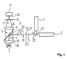
- Fig. 1 shows a schematic representation of an embodiment of an optical arrangement in the beam path of a confocal fluorescence microscope, said arrangement - in the embodiment chosen here - two laser light sources 1, 2, arranged in the illumination / detection beam path 3, 4, 5 means 6 for Separation of the excitation light 8 reflected by the object 7 from the fluorescent light 9 emitted by the object 7, an objective 10 arranged between the device 6 and the object 7 and a detector 11 arranged downstream of the device 6 in the detection beam path 5.
- Fig. 1 shows schematically that the excitation light 8 passes through a beam combiner 12 to the device 6, is reflected by this in the lens 10 and from there to the object 7 passes.
- the fluorescent light 9 in turn passes through the objective 10 to the device 6, passes it with the exception of the reflective region formed in the manner according to the invention as a mirror 13 and passes to the detector 11 via a tube lens 14, a blocking filter wheel 15 and a detection pinhole 16.
- the device 6 comprises a mirror 13, wherein the mirror 13 in the illumination / detection beam path 3, 4, 5 is arranged and dimensioned such that it for the dark field illumination of the object 7 from the laser light sources 1, 2, not expanded excitation beam or the excitation light 8 is reflected in the lens 10 and the coming of the object 7 fluorescent light 9 with full numerical aperture - reduced by the effective in the detection beam 4, 5 cross section of the mirror 13 in the direction of the detector 11 passes.
- the device 6 is designed as a beam splitter, wherein the mirror 13 is integrated there in the middle.
- Fig. 3 shows an alternative embodiment of the device 6 in that it is simply designed as a single mirror 13, wherein the mirror 13 is an independent component.
- the mirror 13 could have an overall mirrored surface as shown in FIG.
- the mirror 13 is likewise embodied as a separate component, the surface of the mirror 13 being subdivided into a reflecting mirror surface 17 and into an absorbing surface 18.
- the back reflections or the back-reflected excitation light 19 can be rendered "harmless", that the sample or the object 7 is skewed, that is not arranged orthogonal to the optical axis 23.
- the back-reflected excitation light 19 is slightly offset from the illumination beam path 20 or the beam path of the excitation light 8, so that the back-reflected excitation light 19 is reflected back along its own beam path 21.
- a light trap 22 is arranged at a suitable location, which is due to the orientation of the beam path 21 away from the illumination beam path 20 and the excitation light 8.
Description
Die Erfindung betrifft eine optische Anordnung im Strahlengang eines konfokalen Fluoreszenzmikroskops, mit mindestens einer Laserlichtquelle, einer im Beleuchtungs-/Detektionsstrahlengang angeordneten Einrichtung zur Trennung des am Objekt reflektierten Anregungslichts von dem vom Objekt abgestrahlten Fluoreszenzlicht, einem zwischen der Einrichtung und dem Objekt angeordneten Objektiv und einem der Einrichtung im Detektionsstrahlengang nachgeordneten Detektor.The invention relates to an optical arrangement in the beam path of a confocal fluorescence microscope, comprising at least one laser light source, a device arranged in the illumination / detection beam path for separating the excitation light reflected from the object from the fluorescence light emitted by the object, an objective arranged between the device and the object the device downstream in the detection beam path detector.
Aus der Praxis ist es bereits seit Jahren bekannt, zur Trennung des am Objekt reflektierten Anregungslichts von dem vom Objekt abgestrahlten Fluoreszenzlicht dichroitische Strahlteiler zu verwenden. Bei der simultanen Mehrfarbanwendung finden entsprechend mehrfach dichroitische Strahlteiler Anwendung. Das vom reflektierten Anregungslicht befreite Fluoreszenzlicht wird - nach Trennung mittels Strahlteiler - mittels eines besonderen Detektors detektiert. Die in der Praxis verwendeten Strahlteiler sind im allgemeinen teuer. Darüber hinaus eignen sich diese Strahlteiler für quantitative Vergleichsmessungen hoher Präzision und hoher Meßdynamik nur wenig, zumal diese Strahlteiler u.a. auch temperaturabhängig sind. Darüberhinaus weisen dichroitische Strahlteiler Transmissionsverluste von etwa 10% für die Detektion auf.From practice, it has been known for years to use dichroic beam splitters to separate the excitation light reflected from the object from the fluorescent light emitted by the object. In the simultaneous multi-color application, multiple dichroic beam splitters are used accordingly. The freed from the reflected excitation light fluorescent light - after separation by means of beam splitter - detected by a special detector. The beam splitters used in practice are generally expensive. In addition, these beam splitters for quantitative comparative measurements of high precision and high dynamic range only a little, especially since these beam splitters u.a. are also temperature dependent. In addition, dichroic beam splitters have transmission losses of about 10% for detection.
Würde man bspw. einen wellenlängenunabhängigen Strahlteiler einsetzen, würde dies die Kosten zweifelsohne herabsetzen. Nachteilig wäre hierbei jedoch, daß man dabei das Streulicht des Anregungslichts vor der Detektion herausfiltern muß, bspw. durch Einsatz eines Sperrfilters. Dies ist wiederum in baulicher Hinsicht aufwendig und verursacht abermals Kosten. Außerdem wird dadurch die Fluoreszenzausbeute verringert. Simultane Mehrfarbanwendungen sind dann jedoch nicht möglich.For example, using a wavelength-independent beam splitter would undoubtedly lower the cost. The disadvantage here, however, that you have to filter out the scattered light of the excitation light before detection, for example. By using a barrier filter. This is in turn structurally complex and again causes costs. In addition, this reduces the fluorescence yield. However, simultaneous multi-color applications are not possible.
Bei Verwendung eines einfachen Strahlteilers gelangt zudem ein Streulichtreflex des Anregungslichts zurück in die Laserlichtquelle und stört die dort stattfindende stimulierte Emission, was sich wiederum durch unerwünschte Intensitätsschwankungen des Laserlichts bemerkbar macht.In addition, when using a simple beam splitter, a scattered light reflection of the excitation light returns to the laser light source and disturbs the stimulated emission taking place there, which in turn is made noticeable by undesired intensity fluctuations of the laser light.
Für höchstauflösende Anwendungen nutzt man zur Beleuchtung bzw. zum Scannen die gesamte numerische Apertur. Dies führt zu einem Beleuchtungsfokus, der in lateraler Richtung sehr klein ist, so daß längere Aufnahmezeiten erforderlich sind. Für Anwendungen, bei denen die Auflösung eine untergeordnete Rolle spielt, ist diese Vorgehensweise aufgrund der längeren Aufnahmezeiten nachteilig.For high-resolution applications, the entire numerical aperture is used for illumination or scanning. This leads to a focus of illumination that is very small in the lateral direction, so that longer recording times are required. For applications in which the resolution plays a minor role, this procedure is disadvantageous because of the longer recording times.
Hinsichtlich der konfokalen Fluoreszenzmikroskopie wird lediglich beispielhaft verwiesen auf Engelhardt und Knebel in "Physik in unserer Zeit", 24. Jahrg., 1993, Nr. 2 "Konfokale Laserscanning-Mikroskopie" und D.K. Hamilton und T. Wilson in Appl. Phys. B 27, 1982, 211-213 "Three-Dimensional Surface Measurement Using the Confocal Scanning Microscope".With regard to confocal fluorescence microscopy, reference is merely made, by way of example, to Engelhardt and Knebel in "Physik in unserer Zeit", 24. Jahrg., 1993, No. 2 "Confocal Laser Scanning Microscopy" and D.K. Hamilton and T. Wilson in Appl. Phys. B 27, 1982, 211-213 "Three Dimensional Surface Measurement Using the Confocal Scanning Microscope".
Der vorliegenden Erfindung liegt nun die Aufgabe zugrunde, eine optische Anordnung im Strahlengang eines konfokalen Fluoreszenzmikroskops derart auszugestalten und weiterzubilden, daß gegenüber der gattungsbildenden Anordnung mit herkömmlichem dichroitischem Strahlteiler eine Erhöhung der Fluoreszenzausbeute bei einfacher Bauweise realisierbar ist.The present invention is based on the object of designing and further developing an optical arrangement in the beam path of a confocal fluorescence microscope in such a way that it is possible to increase the fluorescence yield with a simple construction compared to the generic arrangement with conventional dichroic beam splitter.
Die erfindungsgemäße optische Anordnung im Strahlengang eines konfokalen Fluoreszenzmikroskops löst die voranstehende Aufgabe durch die Merkmale des Patentanspruches 1. Danach ist die eingangs genannte optische Anordnung dadurch gekennzeichnet, daß die Einrichtung einen Spiegel umfaßt und daß der Spiegel im Beleuchtungs-/Detektionsstrahlengang derart angeordnet und dimensioniert ist, daß er zur Dunkelfeldbeleuchtung des Objekts den von der Laserlichtquelle kommenden, nicht aufgeweiteten Anregungsstrahl in das Objektiv reflektiert und das vom Objekt kommende Fluoreszenzlicht mit voller numerischer Apertur - vermindert um den im Detektionsstrahlengang wirksamen Querschnitt des Spiegels - in Richtung des Detektors passieren läßt.The inventive optical arrangement in the beam path of a confocal fluorescence microscope solves the above problem by the features of claim 1. Thereafter, the aforementioned optical arrangement is characterized in that the device comprises a mirror and that the mirror in the illumination / detection beam path is arranged and dimensioned in that, for the dark field illumination of the object, it does not expand the one coming from the laser light source Reflected excitation beam into the lens and the coming of the object fluorescent light with full numerical aperture - reduced by the effective in the detection beam path cross-section of the mirror - pass in the direction of the detector.
In erfindungsgemäßer Weise ist zunächst erkannt worden, daß die Einrichtung einen Spiegel umfaßt und daß der Spiegel im Beleuchtungs-/Detektionsstrahlengang derart angeordnet und dimensioniert ist, daß er zur Dunkelfeldbeleuchtung des Objekts den von der Laserlichtquelle kommenden, nicht aufgeweiteten Anregungsstrahl in das Objektiv reflektiert und das vom Objekt kommende Fluoreszenzlicht mit voller numerischer Apertur - vermindert um den im Detektionsstrahlengang wirksamen Querschnitt des Spiegels - in Richtung des Detektors passieren läßt.In an inventive manner, it has first been recognized that the device comprises a mirror and that the mirror in the illumination / detection beam path is arranged and dimensioned such that it reflects the dark field illumination of the object coming from the laser light source, not expanded excitation beam into the lens and the From the object coming fluorescent light with full numerical aperture - reduced by the effective in the detection beam path cross-section of the mirror - can pass in the direction of the detector.
Erfindungsgemäß ist weiter erkannt worden, daß es sich bei der Einrichtung zum Trennen des am Objekt reflektierten Anregungslichts von dem vom Objekt abgestrahlten Fluoreszenzlicht - anstelle eines herkömmlichen dichroitischen Strahlteilers - um einen Spiegel handeln kann, der im Beleuchtungs-/Detektionsstrahlengang angeordnet ist. Dieser Spiegel ist dabei derart - hinreichend klein - zu dimensionieren, daß er zur Dunkelfeldbeleuchtung des Objekts den von der Laserlichtquelle kommenden, nicht aufgeweiteten Anregungsstrahl in das Objektiv reflektiert und das vom Objekt kommende Fluoreszenzlicht mit voller numerischer Apertur in Richtung des Detektors passieren läßt, wobei das Fluoreszenzlicht um den im Detektionsstrahlengang wirksamen Querschnitt des Spiegels vermindert ist. Der vom Objekt reflektierte Hauptreflex des Anregungslichts wird in vorteilhafter Weise an dem Spiegel aus dem Detektionsstrahlengang herausreflektiert.According to the invention, it has also been recognized that the device for separating the excitation light reflected by the object from the fluorescent light emitted by the object - instead of a conventional dichroic beam splitter - can be a mirror which is arranged in the illumination / detection beam path. This mirror is so - sufficiently small - to be dimensioned so that it for dark field illumination of the object from the laser light source, not expanded excitation beam reflected into the lens and the coming of the object fluorescent light with full numerical aperture can pass in the direction of the detector, the Fluorescence light is reduced by the effective in the detection beam path cross-section of the mirror. The main reflection of the excitation light reflected by the object is reflected out of the detection beam path in an advantageous manner at the mirror.
Aufgrund der hinreichend kleinen Ausgestaltung des Spiegels bzw. der spiegelnden Fläche wird lediglich der nicht aufgeweitete Anregungsstrahl in das Objektiv reflektiert. Durch die Beleuchtung mit einer derart "kleinen" numerischen Apertur (bspw. 10% der sonst üblichen Apertur) erzielt man eine "Dunkelfeldbeleuchtung", die entlang der optischen Achse einen elongierten Fokusbereich mit einem wohl definierten Fokusdurchmesser lateral aufweist. Erfindungsgemäß wird eine hinreichende Beleuchtungstoleranz in der Objektlage entlang der optischen Achse erreicht, was sich auf spezielle Anwendungen in der konfokalen Fluoreszenzmikroskopie besonders günstig auswirkt. Des weiteren ist eine Beleuchtung mit einer hohen intraszenischen Dynamik gewährleistet. Der Vorteil einer solchen hohen intraszenischen Dynamik liegt darin, daß bspw. zwei unmittelbar benachbarte Objekte unterschiedlicher absoluter Fluoreszenzintensität, z.B. Objekt A mit 100% und Objekt B mit 0,05%, in der gleichen Konfokalebene ohne "Überleuchten" des helleren Objekts getrennt voneinander meßbar sind.Due to the sufficiently small configuration of the mirror or the reflecting surface, only the non-expanded excitation beam is reflected into the objective. By lighting with such a "small" numerical aperture (for example 10% of the otherwise usual aperture) one achieves one "Dark field illumination" which has an elongated focus area along the optical axis with a well-defined focus diameter laterally. According to the invention, a sufficient illumination tolerance in the object position along the optical axis is achieved, which has a particularly favorable effect on special applications in confocal fluorescence microscopy. Furthermore, a lighting with a high intrasynamic dynamics is guaranteed. The advantage of such high intrasynamic dynamics is that, for example, two immediately adjacent objects of different absolute fluorescence intensity, eg object A at 100% and object B at 0.05%, can be measured separately in the same confocal plane without "overshadowing" of the brighter object are.
In besonders vorteilhafter Weise ist der Spiegel derart dimensioniert bzw. klein ausgestaltet, daß er für das zu detektierende Fluoreszenzlicht im Detektionsstrahlengang einen Verlust von etwa 1% hervorruft. Dies ermöglicht eine effiziente Detektion mit besonders hohem Dynamikbereich.In a particularly advantageous manner, the mirror is dimensioned or made small such that it causes a loss of about 1% for the fluorescent light to be detected in the detection beam path. This enables efficient detection with a particularly high dynamic range.
Der hier verwendete Spiegel könnte im Rahmen einer besonders einfachen Ausführungsform als unabhängiges Bauteil ausgeführt sein, wobei der Spiegel wiederum von einer Halterung getragen ist. Im Rahmen einer solchen Ausgestaltung entfällt der Einsatz eines herkömmlichen Strahlteilers vollkommen, da hier nämlich im Strahlengang an entsprechender Stelle lediglich der kleine Spiegel angeordnet ist. Im Rahmen einer weiteren Alternative könnte der Spiegel als vorzugsweise integraler verspiegelter Bereich eines - ansonsten herkömmlichen - Strahlteilers ausgeführt sein, wobei der Spiegel bzw. der verspiegelte Bereich zumindest weitgehend in der Mitte des Strahlteilers angeordnet bzw. ausgebildet ist. Dieser kleine - integrale - Spiegel könnte in etwa rund oder elliptisch bzw. oval ausgebildet sein. Letztendlich handelt es sich hier um einen verspiegelten Bereich in der Mitte eines Strahlteilers, der ebenso wie ein isolierter Spiegel den nicht aufgeweiteten Anregungsstrahl in das Objektiv reflektiert. Auch hier findet die Beleuchtung mit einer äußerst kleinen numerischen Apertur zur Begünstigung der Dynamik statt.The mirror used here could be embodied as part of a particularly simple embodiment as an independent component, wherein the mirror is in turn carried by a holder. In the context of such an embodiment, the use of a conventional beam splitter eliminates completely, since only the small mirror is arranged in the beam path at the appropriate point. In the context of a further alternative, the mirror could be embodied as a preferably integral mirrored region of a-otherwise conventional-beam splitter, the mirror or the mirrored region being arranged or formed at least substantially in the middle of the beam splitter. This small - integral - mirror could be approximately round or elliptical or oval. Ultimately, this is a mirrored area in the middle of a beam splitter which, like an isolated mirror, reflects the non-expanded excitation beam into the lens. Again, illumination takes place with a very small numerical aperture to promote dynamics.
Der nicht spiegelnde Bereich des Strahlteilers könnte in Richtung des Detektors in etwa 10% Reflexion und 90% Transmission aufweisen. Dabei könnte es sich im Konkreten um eine Anti-Reflex(AR)-Beschichtung auf der dem Detektor zugewandten Seite des Strahlteilers handeln. Dieser Strahlteiler läßt das Fluoreszenzlicht gemäß dem üblichen - unendlichen - Strahlengang mit der vollen numerischen Apertur - reduziert um das auf den verspiegelten Bereich treffende Fluoreszenzlicht - in Richtung des Detektors passieren. Durch den verspiegelten Bereich entsteht für das zu detektierende Fluoreszenzlicht ein äußerst geringer Verlust, nämlich in Abhängigkeit von der Größe des Spiegels. Hier lassen sich Verluste von lediglich 1% realisieren, was zu der bereits zuvor erwähnten hohen Dynamik führt.The non-reflecting region of the beam splitter could have approximately 10% reflection and 90% transmission in the direction of the detector. Specifically, this could be an anti-reflection (AR) coating on the side of the beam splitter facing the detector. This beam splitter allows the fluorescent light to pass in the direction of the detector in accordance with the customary-infinite-beam path with the full numerical aperture-reduced by the fluorescent light striking the mirrored region. Due to the mirrored area, an extremely low loss arises for the fluorescent light to be detected, namely as a function of the size of the mirror. Here, losses of only 1% can be realized, which leads to the already mentioned high dynamics.
Des weiteren könnte der nicht spiegelnde Bereich des Strahlteilers derart ausgestaltet und ggf. beschichtet sein, daß die optischen Eigenschaften des nicht spiegelnden Bereichs des Strahlteilers zumindest weitgehend temperaturunabhängig sind. Die Reproduzierbarkeit der Messung ist dadurch begünstigt.Furthermore, the non-reflecting region of the beam splitter could be designed and optionally coated such that the optical properties of the non-reflecting region of the beam splitter are at least largely independent of temperature. The reproducibility of the measurement is favored thereby.
Nun gelangt vom Objekt aus nicht nur Fluoreszenzlicht in den Detektionsstrahlengang, sondern auch Rückreflexe des Anregungslichts. Solche Rückreflexe sind unerwünscht. Zur Unterdrückung der Rückreflexe des Anregungslichts am Objekt zurück in die Laserlichtquelle könnte das Objekt schief angeordnet sein. Dies bedeutet, daß das Objekt selbst nicht orthogonal zur optischen Achse angeordnet ist, so daß sich für das rückreflektierte Anregungslicht ein separater Strahlengang ergibt, der zum Beleuchtungsstrahlengang zumindest geringfügig - räumlich - versetzt ist. In diesem besonderen Strahlengang lassen sich ohne weiteres herkömmliche Lichtfallen anordnen, um nämlich das rückreflektierte Anregungslicht wirksam auszublenden.Now, not only does fluorescent light enter the detection beam path from the object, but also back reflections of the excitation light. Such reflexes are undesirable. To suppress the back reflections of the excitation light on the object back into the laser light source, the object could be arranged obliquely. This means that the object itself is not arranged orthogonal to the optical axis, so that there is a separate beam path for the back-reflected excitation light, which is at least slightly - spatially - offset from the illumination beam path. Conventional light traps can be readily arranged in this special beam path in order to effectively block out the back-reflected excitation light.
Im Falle einer erwünschten Objektverschiebung, bspw. zum Auffinden eines weiteren Objekts, ist es von besonderem Vorteil, wenn das Objekt in seiner Ebene derart bewegbar ist, daß der beleuchtete Objektbereich stets den gleichen Abstand zu dem Objektiv aufweist. Dadurch gelangt das am Objekt reflektierte und/oder gestreute Licht gemäß den voranstehenden Ausführungen nicht zurück in die Laserlichtquelle, sondern über den besonderen Strahlengang in eine Lichtfalle.In the case of a desired object displacement, for example, to find another object, it is particularly advantageous if the object is movable in its plane so that the illuminated object area always the has the same distance to the lens. As a result, the light reflected and / or scattered on the object, as described above, does not pass back into the laser light source but via the special beam path into a light trap.
Alternativ zu der Vorkehrung einer Lichtfalle könnte der Spiegel - im Rahmen einer Ausgestaltung als isoliertes Bauteil - einen absorbierenden Bereich zur Absorption des vom Objekt gestreuten und/oder reflektierten Anregungslichts aufweisen. Die Vorkehrung besonderer Lichtfallen ist dabei nicht mehr erforderlich, wodurch sich eine räumliche Reduktion der Anordnung ergibt. So könnte der Spiegel - im Rahmen einer runden oder elliptischen bzw. ovalen Ausgestaltung - einen spiegelnden bzw. reflektierenden Bereich und einen absorbierenden Bereich aufweisen.As an alternative to the provision of a light trap, the mirror could-in the context of an embodiment as an insulated component-have an absorbing region for absorbing the excitation light scattered and / or reflected by the object. The provision of special light traps is no longer necessary, resulting in a spatial reduction of the arrangement. Thus, the mirror could-in the context of a round or elliptical or oval configuration-have a reflective or reflecting area and an absorbing area.
Ebenso ist es möglich, daß der Strahlteiler neben dem verspiegelten Bereich einen absorbierenden Bereich zur Absorption des vom Objekt gestreuten und/oder reflektierten Anregungslichts aufweist. Auch im Rahmen einer solchen Ausgestaltung kann die Vorkehrung einer besonderen Lichtfalle entfallen, so daß auch diese Ausgestaltung den Vorteil in sich birgt, die Anordnung mit geringstem Raumbedarf bauen zu können.It is likewise possible for the beam splitter to have, in addition to the mirrored region, an absorbing region for absorbing the excitation light scattered and / or reflected by the object. Even in the context of such an embodiment, the provision of a special light trap can be omitted, so that this embodiment also has the advantage of being able to build the arrangement with minimal space requirements.
Schließlich ist es von ganz besonderem Vorteil, wenn durch ein geeignetes Verhältnis von Strahldivergenz zur Wellenlänge der verwendeten Laserlichtquellen eine zumindest annährend gleiche - axiale - Fokuslage möglich ist. Dadurch ist zum einen die notwendige Beleuchtungstoleranz in der Objektlage entlang der optischen Achse gegeben und ist zum anderen eine Beleuchtung mit einer hohen intraszenischen Dynamik gewährleistet. Hierzu wird zur Vermeidung von Wiederholungen auf die voranstehenden Ausführungen verwiesen.Finally, it is of very particular advantage if at least approximately the same axial focus position is possible by means of a suitable ratio of beam divergence to the wavelength of the laser light sources used. As a result, on the one hand, the necessary illumination tolerance in the object position is given along the optical axis and, on the other hand, illumination with a high intrasynic dynamic is ensured. Reference is made to avoid repetition of the above statements.
Es gibt nun verschiedene Möglichkeiten, die Lehre der vorliegenden Erfindung in vorteilhafter Weise auszugestalten und weiterzubilden. Dazu ist einerseits auf die dem Patentanspruch 1 nachgeordneten Ansprüche, andererseits auf die nachfolgende Erläuterung von Ausführungsbeispielen der Erfindung anhand der Zeichnung zu verweisen. In Verbindung mit der Erläuterung der bevorzugten Ausführungsbeispiele der Erfindung anhand der Zeichnung werden auch im allgemeinen bevorzugte Ausgestaltungen und Weiterbildungen der Lehre erläutert. In der Zeichnung zeigt
- Fig. 1
- in einer schematischen Darstellung den grundsätzlichen Aufbau einer erfindungsgemäßen optischen Anordnung im Strahlengang eines konfokalen Fluoreszenzmikroskops,
- Fig. 2
- in einer schematischen Darstellung einen Strahlteiler mit mittigem Spiegel,
- Fig. 3
- in einer schematischen Darstellung einen anstelle des Strahlteilers verwendbaren Spiegel als separates Bauteil und
- Fig. 4
- in einer schematischen Darstellung einen Spiegel mit integralem reflektierenden und absorbierenden Bereich.
- Fig. 1
- 2 shows a schematic representation of the basic structure of an optical arrangement according to the invention in the beam path of a confocal fluorescence microscope,
- Fig. 2
- in a schematic representation of a beam splitter with central mirror,
- Fig. 3
- in a schematic representation of a usable instead of the beam splitter mirror as a separate component and
- Fig. 4
- in a schematic representation, a mirror with integral reflecting and absorbing area.
Fig. 1 zeigt in einer schematischen Darstellung ein Ausführungsbeispiel einer optischen Anordnung im Strahlengang eines konfokalen Fluoreszenzmikroskops, wobei diese Anordnung - bei dem hier gewählten Ausführungsbeispiel - zwei Laserlichtquellen 1, 2, eine im Beleuchtungs-/Detektionsstrahlengang 3, 4, 5 angeordnete Einrichtung 6 zur Trennung des am Objekt 7 reflektierten Anregungslichts 8 von dem vom Objekt 7 abgestrahlten Fluoreszenzlicht 9, ein zwischen der Einrichtung 6 und dem Objekt 7 angeordnetes Objektiv 10 und einen der Einrichtung 6 im Detektionsstrahlengang 5 nachgeordneten Detektor 11 umfaßt.Fig. 1 shows a schematic representation of an embodiment of an optical arrangement in the beam path of a confocal fluorescence microscope, said arrangement - in the embodiment chosen here - two
Fig. 1 läßt schematisch erkennen, daß das Anregungslicht 8 über einen Strahlvereiniger 12 zu der Einrichtung 6 gelangt, von dieser in das Objektiv 10 reflektiert wird und von dort aus zum Objekt 7 gelangt. Das Fluoreszenzlicht 9 gelangt wiederum durch das Objektiv 10 hindurch zu der Einrichtung 6, passiert diese mit Ausnahme des in erfindungsgemäßer Weise als Spiegel 13 ausgebildeten reflektierenden Bereichs und gelangt über eine Tubuslinse 14, ein Sperrfilterrad 15 und eine Detektionslochblende 16 zu dem Detektor 11.Fig. 1 shows schematically that the
Erfindungsgemäß umfaßt die Einrichtung 6 einen Spiegel 13, wobei der Spiegel 13 im Beleuchtungs-/Detektionsstrahlengang 3, 4, 5 derart angeordnet und dimensioniert ist, daß er zur Dunkelfeldbeleuchtung des Objekts 7 den von den Laserlichtquellen 1, 2 kommenden, nicht aufgeweiteten Anregungsstrahl bzw. das Anregungslicht 8 in das Objektiv 10 reflektiert und das vom Objekt 7 kommende Fluoreszenzlicht 9 mit voller numerischer Apertur - vermindert um den im Detektionsstrahlengang 4, 5 wirksamen Querschnitt des Spiegels 13 in Richtung des Detektors 11 passieren läßt.According to the invention, the
Bei dem in den Fig. 1 und 2 gezeigten Ausführungsbeispiel ist die Einrichtung 6 als Strahlteiler ausgeführt, wobei dort mittig der Spiegel 13 integriert ist.In the embodiment shown in FIGS. 1 and 2, the
Fig. 3 zeigt eine alternative Ausgestaltung der Einrichtung 6 dahingehend, daß diese schlicht und einfach als singulärer Spiegel 13 ausgeführt ist, wobei es sich bei dem Spiegel 13 um ein eigenständiges Bauteil handelt. Der Spiegel 13 könnte eine insgesamt verspiegelte Fläche gemäß der Darstellung in Fig. 3 aufweisen.Fig. 3 shows an alternative embodiment of the
Bei dem in Fig. 4 dargestellten Ausführungsbeispiel ist der Spiegel 13 ebenfalls als separates Bauteil ausgeführt, wobei die Fläche des Spiegels 13 in eine reflektierende Spiegelfläche 17 und in eine absorbierende Fläche 18 unterteilt ist. Durch diese Maßnahme erübrigt sich die Vorkehrung einer separaten Lichtfalle für etwa rückreflektiertes Anregungslicht 19.In the exemplary embodiment illustrated in FIG. 4, the
Sofern als Einrichtung 6 ein Strahlteiler beispielsweise gemäß der Darstellung in den Fig. 1 und 2, aber auch eine Ausführungsform nach den Fig. 3 und 4 verwendet wird, lassen sich die Rückreflexe bzw. läßt sich das rückreflektierte Anregungslicht 19 dadurch "unschädlich" machen, daß die Probe bzw. das Objekt 7 schief gestellt, d.h. nicht orthogonal zur optischen Achse 23 angeordnet ist. Dadurch wird das rückreflektierte Anregungslicht 19 geringfügig zum Beleuchtungsstrahlengang 20 bzw. zum Strahlengang des Anregungslichts 8 versetzt, so daß das rückreflektierte Anregungslicht 19 entlang eines eigenen Strahlengangs 21 rückreflektiert wird. Dort ist an geeigneter Stelle eine Lichtfalle 22 angeordnet, die aufgrund der Ausrichtung des Strahlengangs 21 abseits des Beleuchtungsstrahlengangs 20 bzw. des Anregungslichts 8 liegt.If a beam splitter, for example according to the illustration in FIGS. 1 and 2, but also an embodiment according to FIGS. 3 and 4, is used as the
Hinsichtlich weiterer vorteilhafter Ausgestaltungen der vorliegenden Erfindung wird zur Vermeidung von Wiederholungen auf die Ausführungen im allgemeinen Teil der Beschreibung verwiesen.With regard to further advantageous embodiments of the present invention, reference is made to the statements in the general part of the description to avoid repetition.
- 11
- LaserlichtquelleLaser light source
- 22
- LaserlichtquelleLaser light source
- 33
- BeleuchtungsstrahlengangIllumination beam path
- 44
- Beleuchtungs-/DetektionsstrahlengangIllumination / detection beam path
- 55
- DetektionsstrahlengangDetection beam path
- 66
- Einrichtung zur Trennung des am Objekt reflektierten Anregungslichts von dem vom Objekt abgestrahlten FluoreszenzlichtDevice for separating the excitation light reflected by the object from the fluorescent light emitted by the object
- 77
- Objektobject
- 88th
- Anregungslichtexcitation light
- 99
- Fluoreszenzlichtfluorescent light
- 1010
- Objektivlens
- 1111
- Detektordetector
- 1212
- Strahlvereinigerbeam combiner
- 1313
- Spiegelmirror
- 1414
- Tubuslinsetube lens
- 1515
- SperrfilterradSperrfilterrad
- 1616
- DetektionslochblendeDetection pinhole
- 1717
- Spiegelflächemirror surface
- 1818
- absorbierende Flächeabsorbing surface
- 1919
- rückreflektiertes Anregungslichtback-reflected excitation light
- 2020
- BeleuchtungsstrahlengangIllumination beam path
- 2121
- Strahlengang des rückreflektierten AnregungslichtsBeam path of the back-reflected excitation light
- 2222
- Lichtfallelight trap
- 2323
- optische Achseoptical axis
Claims (10)
- Confocal fluorescence scanning microscope having an optical arrangement in the beam path of the confocal fluorescence microscope, having at least one laser light source (1, 2), a device (6) arranged in the illumination/detection beam path (3, 4, 5) to separate the exciting light (8) reflected at the object (7) from the fluorescent light (9) radiated by the object (7), an objective (10) arranged between the device (6) and the object (7), and a detector (11) arranged downstream of the device (6) in the detection beam path (5), the device (6) comprising a mirror (13), which deflects the light of the light source towards the objective (10) and at the same time shades a proportion of the fluorescent light (9) and thus permits the fluorescent light (9) coming from the object (7) to pass in the direction of the detector (11) with full numerical aperture, reduced by the effective cross section of the mirror (13) in the detection beam path (5), the at least one light source (1,2) being a laser light source, the non-widened exciting light of the laser light source having a substantially smaller beam cross section than the cross section of the fluorescent light emerging from the objective (10), and the mirror (13) being dimensioned in such a way that, for the fluorescent light (9) to be detected, it causes a loss in the detection beam path (5) of about one per cent.
- Confocal fluorescence scanning microscope according to Claim 1, characterized in that the mirror (13) is designed as an independent component.
- Confocal fluorescence scanning microscope according to Claim 2, characterized in that the mirror (13) is carried by a holder.
- Confocal fluorescence scanning microscope according to Claim 1, characterized in that the mirror (13) is designed as a preferably integrally silvered area of a beam splitter.
- Confocal fluorescence scanning microscope according to Claim 4, characterized in that the mirror (13) is arranged at the centre of the beam splitter (6) and is circular or elliptical.
- Confocal fluorescence scanning microscope according to Claim 5, characterized in that the non-reflective area of the beam splitter (6) exhibits approximately 10% reflection and 90% transmission in the direction of the detector (11).
- Confocal fluorescence scanning microscope according to one of Claims 1 to 6, characterized in that in order to suppress the back-reflection of the exciting light (8) at the object (7) back into the laser light source (1, 2), the object (7) is arranged crookedly, that is to say not orthogonal to the optical axis (23), and in that for the back-reflected exciting light (19), a light trap (22) is provided in its beam path (21), which is at least slightly offset with respect to the illumination beam path (20).
- Confocal fluorescence scanning microscope according to one of Claims 1 to 7, characterized in that the object (7) can be moved in its plane in such a way that the illuminated object area is always at the same distance from the objective (10).
- Confocal fluorescence scanning microscope according to one of Claims 1 to 8, characterized in that the mirror (13) has an absorbing area (18) to absorb the exciting light (8) scattered by the object (7), and in that in addition to the silvered area, the absorbing area (18) for absorbing the exciting light (8) scattered by the object (7) is provided on the beam splitter.
- Confocal fluorescence scanning microscope according to one of Claims 1 to 9, characterized in that by means of a suitable ratio between beam divergence and wavelength of the laser light sources (1, 2) used, an at least approximately identical focal position can be implemented.
Applications Claiming Priority (3)
| Application Number | Priority Date | Filing Date | Title |
|---|---|---|---|
| DE19842153 | 1998-09-15 | ||
| DE19842153A DE19842153C2 (en) | 1998-09-15 | 1998-09-15 | fluorescence microscope |
| PCT/DE1999/002910 WO2000016149A1 (en) | 1998-09-15 | 1999-09-13 | Optical system in the ray path of a confocal fluorescence microscope |
Publications (2)
| Publication Number | Publication Date |
|---|---|
| EP1031055A1 EP1031055A1 (en) | 2000-08-30 |
| EP1031055B1 true EP1031055B1 (en) | 2006-01-25 |
Family
ID=7880995
Family Applications (1)
| Application Number | Title | Priority Date | Filing Date |
|---|---|---|---|
| EP99955690A Revoked EP1031055B1 (en) | 1998-09-15 | 1999-09-13 | Optical system in the ray path of a confocal fluorescence microscope |
Country Status (5)
| Country | Link |
|---|---|
| US (1) | US6785302B1 (en) |
| EP (1) | EP1031055B1 (en) |
| JP (1) | JP4197395B2 (en) |
| DE (2) | DE19842153C2 (en) |
| WO (1) | WO2000016149A1 (en) |
Families Citing this family (20)
| Publication number | Priority date | Publication date | Assignee | Title |
|---|---|---|---|---|
| WO2000050878A1 (en) * | 1999-02-26 | 2000-08-31 | Gsi Lumonics, Inc. | Imaging system for an optical scanner |
| US6355934B1 (en) | 1999-02-26 | 2002-03-12 | Packard Biochip Technologies | Imaging system for an optical scanner |
| DE19923822A1 (en) † | 1999-05-19 | 2000-11-23 | Zeiss Carl Jena Gmbh | Optical scanning configuration for detecting fluorescent light and for suppressing stray light arising from an illuminated test detected through a lens creates a shaded area for stray light in a focal plane. |
| US6795189B2 (en) * | 2000-06-15 | 2004-09-21 | Packard Instrument Company | Universal microplate analyzer |
| EP1164402B1 (en) * | 2000-06-17 | 2010-04-28 | Leica Microsystems CMS GmbH | Scanning microscope with multiband illumination and optical element for a scanning microsscope with multiband illumination |
| FR2813121A1 (en) * | 2000-08-21 | 2002-02-22 | Claude Weisbuch | PERFECTED DEVICE FOR SUPPORTING CHROMOPHORIC ELEMENTS |
| US6826424B1 (en) * | 2000-12-19 | 2004-11-30 | Haishan Zeng | Methods and apparatus for fluorescence and reflectance imaging and spectroscopy and for contemporaneous measurements of electromagnetic radiation with multiple measuring devices |
| US6750457B2 (en) * | 2001-08-29 | 2004-06-15 | Becton Dickinson And Company | System for high throughput analysis |
| DE10143481A1 (en) * | 2001-09-05 | 2003-03-20 | Europ Lab Molekularbiolog | Microscope, especially TIRM type microscope, has a beam cross-section at the inlet to the adapter that is much smaller than the adapter cross section so that a maximum range of viewing and illuminating wavelengths can be used |
| DE10144062B4 (en) * | 2001-09-07 | 2010-05-27 | Leica Microsystems Ag | Microscope with a lighting reflection |
| US6888148B2 (en) * | 2001-12-10 | 2005-05-03 | Carl Zeiss Jena Gmbh | Arrangement for the optical capture of excited and /or back scattered light beam in a sample |
| DE10327987A1 (en) * | 2003-06-21 | 2005-01-20 | MAX-PLANCK-Gesellschaft zur Förderung der Wissenschaften e.V. | Confocal optical system |
| DE10332073A1 (en) * | 2003-07-11 | 2005-02-10 | Carl Zeiss Jena Gmbh | Arrangement for the optical detection of light radiation with double objective arrangement excited and / or backscattered in a sample |
| FR2860606B1 (en) * | 2003-10-07 | 2006-01-21 | Thales Sa | MULTIMODE-SINGLE-MODE CONVERTER, PARTICULARLY FOR LASER SOURCE WITH MULTIMODE AMPLIFIER |
| FR2869686B1 (en) * | 2003-12-11 | 2009-06-05 | Flowgene Sa | ELLIPTICAL BED LIGHT DETECTOR |
| DE102006056429B3 (en) * | 2006-11-28 | 2008-02-14 | Leica Microsystems Cms Gmbh | Microscope-type imaging device for examining biological and medical test samples, has spatially separating beam splitter for partly separating coherent detection light from incoherent light |
| DE102007024074B4 (en) | 2007-05-22 | 2022-09-15 | Leica Microsystems Cms Gmbh | microscope |
| JP6058977B2 (en) * | 2012-11-15 | 2017-01-11 | シャープ株式会社 | Fluorescence detection device |
| JP6176327B2 (en) * | 2013-07-11 | 2017-08-09 | 株式会社島津製作所 | Raman spectrometer |
| EP3542710A1 (en) * | 2018-03-23 | 2019-09-25 | JenLab GmbH | Multimodal imaging system and method for non-invasive examination of an object |
Citations (1)
| Publication number | Priority date | Publication date | Assignee | Title |
|---|---|---|---|---|
| US5192980A (en) * | 1990-06-27 | 1993-03-09 | A. E. Dixon | Apparatus and method for method for spatially- and spectrally-resolved measurements |
Family Cites Families (19)
| Publication number | Priority date | Publication date | Assignee | Title |
|---|---|---|---|---|
| US4744663A (en) * | 1984-12-14 | 1988-05-17 | Nippon Kogaku K.K. | Pattern position detection apparatus using laser beam |
| DE3742806A1 (en) * | 1987-12-17 | 1989-07-13 | Zeiss Carl Fa | Method and device for producing fluorescence images |
| JPH03269405A (en) * | 1990-03-19 | 1991-12-02 | Fujitsu Ltd | Fluorescent microscope |
| US5127730A (en) * | 1990-08-10 | 1992-07-07 | Regents Of The University Of Minnesota | Multi-color laser scanning confocal imaging system |
| USH1344H (en) * | 1990-10-09 | 1994-08-02 | The United States Of America As Represented By The Secretary Of The Army | Portable automatic sensor for toxic gases |
| GB2254444B (en) * | 1991-03-25 | 1994-06-15 | Birkbeck College | Laser microscopy |
| CH685650A5 (en) * | 1991-07-20 | 1995-08-31 | Tencor Instruments | Device for surface inspections. |
| JP3102938B2 (en) * | 1991-12-30 | 2000-10-23 | シスメックス株式会社 | Particle image analyzer |
| DE4243144B4 (en) * | 1992-12-19 | 2008-08-21 | BRUKER OPTICS, Inc., Billerica | Lens for a FT Raman microscope |
| JP3144513B2 (en) * | 1993-06-17 | 2001-03-12 | 富士写真フイルム株式会社 | Fluorescence microscope |
| DE4343076C2 (en) * | 1993-12-16 | 1997-04-03 | Phototherm Dr Petry Gmbh | Device for photothermal testing of a surface of an object in particular being moved |
| US5734498A (en) * | 1994-05-09 | 1998-03-31 | The Regents Of The University Of California | Illuminator elements for conventional light microscopes |
| JP3537205B2 (en) * | 1995-02-02 | 2004-06-14 | オリンパス株式会社 | Microscope equipment |
| JPH09281045A (en) * | 1996-04-10 | 1997-10-31 | Kdk Corp | Optical measurement of mevalonic acid |
| JPH1096862A (en) * | 1996-09-20 | 1998-04-14 | Bunshi Bio Photonics Kenkyusho:Kk | Down lighting fluorescence microscope |
| JP3269405B2 (en) | 1996-10-08 | 2002-03-25 | 株式会社東京精密 | Automatic measuring device for numerically controlled machine tools |
| JPH10142507A (en) * | 1996-11-11 | 1998-05-29 | Olympus Optical Co Ltd | Laser scanning microscope |
| JPH1198372A (en) * | 1997-09-18 | 1999-04-09 | Olympus Optical Co Ltd | Method for adjusting color |
| US6445491B2 (en) * | 1999-01-29 | 2002-09-03 | Irma America, Inc. | Method and apparatus for optical sectioning and imaging using time-gated parametric image amplification |
-
1998
- 1998-09-15 DE DE19842153A patent/DE19842153C2/en not_active Revoked
-
1999
- 1999-09-13 DE DE59913082T patent/DE59913082D1/en not_active Expired - Lifetime
- 1999-09-13 EP EP99955690A patent/EP1031055B1/en not_active Revoked
- 1999-09-13 WO PCT/DE1999/002910 patent/WO2000016149A1/en active IP Right Grant
- 1999-09-13 JP JP2000570627A patent/JP4197395B2/en not_active Expired - Lifetime
- 1999-09-13 US US09/554,083 patent/US6785302B1/en not_active Expired - Lifetime
Patent Citations (1)
| Publication number | Priority date | Publication date | Assignee | Title |
|---|---|---|---|---|
| US5192980A (en) * | 1990-06-27 | 1993-03-09 | A. E. Dixon | Apparatus and method for method for spatially- and spectrally-resolved measurements |
Also Published As
| Publication number | Publication date |
|---|---|
| DE59913082D1 (en) | 2006-04-13 |
| US6785302B1 (en) | 2004-08-31 |
| WO2000016149A1 (en) | 2000-03-23 |
| DE19842153C2 (en) | 2003-07-31 |
| JP2002525651A (en) | 2002-08-13 |
| EP1031055A1 (en) | 2000-08-30 |
| DE19842153A1 (en) | 2000-03-16 |
| JP4197395B2 (en) | 2008-12-17 |
Similar Documents
| Publication | Publication Date | Title |
|---|---|---|
| EP1031055B1 (en) | Optical system in the ray path of a confocal fluorescence microscope | |
| EP3262452B1 (en) | Device and method for detecting light | |
| EP1053497B1 (en) | Device for simultaneously detecting several spectral ranges of a light beam | |
| EP0978009B1 (en) | System for calibrating a laser scanning microscope | |
| EP2185919A1 (en) | Sted fluorescence microscopy having two-photon excitation | |
| DE102012019472A1 (en) | Optical filter device, in particular for microscopes | |
| EP1093001A2 (en) | Confocal laserscan microscope | |
| EP1698929B1 (en) | Objective and microscope | |
| EP1122574B1 (en) | Microscope arrangement | |
| EP3084502B1 (en) | Multi-color scanning microscope | |
| DE102015102631A1 (en) | Apparatus and method for detecting light | |
| EP1651992B1 (en) | Scanning microscope | |
| DE102005022125A1 (en) | Light pattern microscope with auto focus mechanism, uses excitation or detection beam path with auto focus for detecting position of focal plane | |
| WO2024012878A1 (en) | Apparatus for chromatic confocal measurement of distances | |
| EP2784564A1 (en) | Light microscope and method for examining a microscopic sample | |
| DE10021379A1 (en) | Optical measuring arrangement, in particular for measuring the layer thickness | |
| DE102004032953A1 (en) | phase filter | |
| DE10300157B4 (en) | Confocal 4-Pi Microscope and Confocal 4-Pi Microscopy Method | |
| DE102006011277A1 (en) | Laser scanning microscope for detecting fluorescent radiation, has detection module with detection unit that detects linear sections in such a manner that linear probe radiation bundle is produced for each section | |
| DE102006017841A1 (en) | Laser scanning microscope with main beam splitter for the spatial separation of illumination and detection radiation | |
| DE10102033B4 (en) | Device and scanning microscope for the simultaneous detection of multiple spectral regions of a light beam | |
| EP1049952B1 (en) | Arrangement for optically scanning an object | |
| DE10001954B4 (en) | Laser scanning microscope | |
| DE4130698C2 (en) | Illumination device for a microscope | |
| DE102004052955B4 (en) | Optical arrangement |
Legal Events
| Date | Code | Title | Description |
|---|---|---|---|
| PUAI | Public reference made under article 153(3) epc to a published international application that has entered the european phase |
Free format text: ORIGINAL CODE: 0009012 |
|
| 17P | Request for examination filed |
Effective date: 20000429 |
|
| AK | Designated contracting states |
Kind code of ref document: A1 Designated state(s): AT BE CH CY DE DK ES FI FR GB GR IE IT LI LU MC NL PT SE |
|
| 17Q | First examination report despatched |
Effective date: 20030818 |
|
| RAP1 | Party data changed (applicant data changed or rights of an application transferred) |
Owner name: LEICA MICROSYSTEMS HEIDELBERG GMBH |
|
| RBV | Designated contracting states (corrected) |
Designated state(s): CH DE FR GB LI |
|
| GRAP | Despatch of communication of intention to grant a patent |
Free format text: ORIGINAL CODE: EPIDOSNIGR1 |
|
| GRAS | Grant fee paid |
Free format text: ORIGINAL CODE: EPIDOSNIGR3 |
|
| GRAA | (expected) grant |
Free format text: ORIGINAL CODE: 0009210 |
|
| AK | Designated contracting states |
Kind code of ref document: B1 Designated state(s): CH DE FR GB LI |
|
| REG | Reference to a national code |
Ref country code: GB Ref legal event code: FG4D Free format text: NOT ENGLISH |
|
| REG | Reference to a national code |
Ref country code: CH Ref legal event code: EP |
|
| REF | Corresponds to: |
Ref document number: 59913082 Country of ref document: DE Date of ref document: 20060413 Kind code of ref document: P |
|
| GBT | Gb: translation of ep patent filed (gb section 77(6)(a)/1977) |
Effective date: 20060327 |
|
| RAP2 | Party data changed (patent owner data changed or rights of a patent transferred) |
Owner name: LEICA MICROSYSTEMS CMS GMBH |
|
| ET | Fr: translation filed | ||
| PG25 | Lapsed in a contracting state [announced via postgrant information from national office to epo] |
Ref country code: LI Free format text: LAPSE BECAUSE OF NON-PAYMENT OF DUE FEES Effective date: 20060930 Ref country code: CH Free format text: LAPSE BECAUSE OF NON-PAYMENT OF DUE FEES Effective date: 20060930 |
|
| PLBI | Opposition filed |
Free format text: ORIGINAL CODE: 0009260 |
|
| PLAX | Notice of opposition and request to file observation + time limit sent |
Free format text: ORIGINAL CODE: EPIDOSNOBS2 |
|
| 26 | Opposition filed |
Opponent name: CARL ZEISS JENA GMBH Effective date: 20061020 |
|
| REG | Reference to a national code |
Ref country code: FR Ref legal event code: TP |
|
| PLBB | Reply of patent proprietor to notice(s) of opposition received |
Free format text: ORIGINAL CODE: EPIDOSNOBS3 |
|
| REG | Reference to a national code |
Ref country code: GB Ref legal event code: 732E |
|
| REG | Reference to a national code |
Ref country code: CH Ref legal event code: PL |
|
| REG | Reference to a national code |
Ref country code: DE Ref legal event code: R103 Ref document number: 59913082 Country of ref document: DE Ref country code: DE Ref legal event code: R064 Ref document number: 59913082 Country of ref document: DE |
|
| PGFP | Annual fee paid to national office [announced via postgrant information from national office to epo] |
Ref country code: DE Payment date: 20110923 Year of fee payment: 13 Ref country code: FR Payment date: 20110928 Year of fee payment: 13 Ref country code: GB Payment date: 20110920 Year of fee payment: 13 |
|
| RDAF | Communication despatched that patent is revoked |
Free format text: ORIGINAL CODE: EPIDOSNREV1 |
|
| RDAG | Patent revoked |
Free format text: ORIGINAL CODE: 0009271 |
|
| STAA | Information on the status of an ep patent application or granted ep patent |
Free format text: STATUS: PATENT REVOKED |
|
| 27W | Patent revoked |
Effective date: 20111110 |
|
| GBPR | Gb: patent revoked under art. 102 of the ep convention designating the uk as contracting state |
Effective date: 20111110 |
|
| REG | Reference to a national code |
Ref country code: DE Ref legal event code: R107 Ref document number: 59913082 Country of ref document: DE Effective date: 20120614 |