EP1031402A2 - Chain saw for branch cutting - Google Patents
Chain saw for branch cutting Download PDFInfo
- Publication number
- EP1031402A2 EP1031402A2 EP00830109A EP00830109A EP1031402A2 EP 1031402 A2 EP1031402 A2 EP 1031402A2 EP 00830109 A EP00830109 A EP 00830109A EP 00830109 A EP00830109 A EP 00830109A EP 1031402 A2 EP1031402 A2 EP 1031402A2
- Authority
- EP
- European Patent Office
- Prior art keywords
- oil
- chain saw
- fitted
- main body
- washer
- Prior art date
- Legal status (The legal status is an assumption and is not a legal conclusion. Google has not performed a legal analysis and makes no representation as to the accuracy of the status listed.)
- Withdrawn
Links
Images

Classifications
-
- B—PERFORMING OPERATIONS; TRANSPORTING
- B27—WORKING OR PRESERVING WOOD OR SIMILAR MATERIAL; NAILING OR STAPLING MACHINES IN GENERAL
- B27B—SAWS FOR WOOD OR SIMILAR MATERIAL; COMPONENTS OR ACCESSORIES THEREFOR
- B27B17/00—Chain saws; Equipment therefor
- B27B17/08—Drives or gearings; Devices for swivelling or tilting the chain saw
-
- B—PERFORMING OPERATIONS; TRANSPORTING
- B27—WORKING OR PRESERVING WOOD OR SIMILAR MATERIAL; NAILING OR STAPLING MACHINES IN GENERAL
- B27B—SAWS FOR WOOD OR SIMILAR MATERIAL; COMPONENTS OR ACCESSORIES THEREFOR
- B27B17/00—Chain saws; Equipment therefor
Abstract
Description
- The invention concerns a tool for cutting branches with diameters of up to 200 mm and above. High branches may be cut by fitting a telescopic extension piece. The cutting of branches is easy and safe with this tool. The tool is designed in such a way that if any parts become unloosened the bracket will not release itself from the bevel gear pair and the tool will therefore not fall, which is the most dangerous of all possible occurrences. The safety of the tool is also guaranteed by the semi-truncated bell-shaped element which ensures that the same protection is provided by means of the ring nut which, once tightened, is blocked with a safety rod. The tool therefore guarantees a very high level of safety, which is an absolute requirement for compliance with EU regulations.
- The invention falls within the technical field of human requirements and within the application field of instrument and tool manufacturing. The tool may be easily used either during professional activities or for hobby purposes.
- It may used directly by the operator or fixed to a rod fitted with a bevel gear pair to which the DC or AC driving power is provided by an internal combustion engine. It has been rationally designed and the manufacture and maintenance is easy. An interesting point is that, as shown in more detail below, the parts from which it is formed - such as oil tank, pump, filters, positioning washer, collar or bell-shaped bracket, oil sump, blade and chain etc are easily and rapidly removed and replaced.
- This invention is more easily operated and maintained than previous solutions as a result of the above-mentioned ease which parts may be removed and replaced.
- The invention is described below, where reference is made to the current version and the following drawings, which are attached herewith:
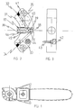
- Fig. 1 Schematic diagram of tool
- Fig. 2 Sectional view of self-priming pump
- Fig. 3 Side view of self-priming pump
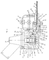
- Fig. 4 Schematic sectional view of tool
- Fig. 5 Schematic exploded view of tool
- Fig. 6 Detail of clamp and truncated cone
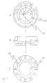
- Fig. 7 Positioning washer: a) bottom view; b) side view; c) top view.
-
- This tool is use for cutting branches. It is formed by a main body, a self-priming pump, a joint, a positioning washer, a collar bracket, an oil sump, hook supports, stud inserts, etc.
Main body 1 holds bearing 27 which has the role of holding thetransmission axis 4, anoil tank 16 which contains the chain lubrication oil, two ormore inserts 14 which are necessary to fix the oil sump and the blade, apump 19 to send the oil from the tank to the inlet at the chain, anoil filter 18, atransmission axis 4 to run on thebearing 27, ajoint 22, apre-loading spring 2 for the bevel gear pair, apositioning washer 21, a pre-loading screw for apre-loading spring 25 and anotherscrew 26 to fix thebracket 20 to the collar, abevel gear pair 23, acam 3, anadjustment washer 6 and a transmission reel 5, aring seal 29, twostuds 12, four ormore fixing screws 13, a plug withgasket 16 for the tank 17, aring seal 15, aprotection sump 7, twobushes 10 for nut support, ascrew 11 to regulate the chain blade, a chain-tensioningpin 9, two self-blocking nuts 8. - A low profile chain runs around the
blade 30. Themain body 1 is fitted with aninlet hole 51 for the passage of oil, adischarge hole 52, and anair inlet hole 53 to the tank. - The self-priming pump is without doubt an original aspect of the invention. It has been specifically designed for use in the tool in question and is formed by a
main body 31, aplug 32 forpipe 35 for oil suction, apipe 33 for oil discharge, aplug 34, a cap 36 for contact with the cam, apiston 37 for oil pumping, a valve formed by aspring 38 and aring seal 39, a calibrated hole for oil suction,hole 41 to fix the pump screws, a sinteredfilter 42 for suction of air from the tank, acheck valve 43 to reset the air circuit, ahole 44 for oil discharge, apump cylinder 45, apiston return spring 46. -
Joint 22 which fits inshaft 4 is replaceable with others depending on the power takeoff which is used. - Positioning
washer 21 is formed byposition 47 for the angular positioning of the tool, ablocking device 48, spokedelements 49. It is fitted withair inlet holes 50. Thebracket 20 may also be replaced by a semi-truncated bell-shaped element 51 Fig. 6, fitted withring nut 52 in which a threaded rod is fitted 53 which ends with awasher 54 covered with a layer of anti-slip rubber. The hook supports 55 fitted to themain body 1 are asymmetric in order to make it easier to determine the side on which the cut must be made. - The
stud inserts 14 allow the immediate replacement of the studs if they are worn.
Claims (8)
- Chain saw for cutting branches, comprising a main body, a self-priming pump, a joint, a positioning washer, a collar bracket, an oil sump, hook supports, stud inserts inserted in the main body (1), a bearing (27), a tank (16), two or more inserts (14), a pump (19), an oil filter (18), a transmission axis (22), a spring (2), a positioning washer (21), a pre-loading screw (24) with spring (25) and a tenon screw (26), a collar bracket (20), a bevel gear pair (23), a cam (3), an adjustment washer (6) and a transmission reel (5), a seal ring (29), two studs (12), four or more fixing screws (13), a tank plug (16) with gasket, a seal ring (15), a protection sump (7), two nut support bushes (10), a chain regulating screw (11), a chain-tensioning pin (9), two self-blocking nuts (8), an element (28) around which the cutting chain (30) runs. Oil inlet (51) and discharge (52) holes and installed in the main body and an air inlet hole (53) for the tank.
- Chain saw for cutting branches, according to Claim 1, characterised by the fact that the self-priming pump comprises a main body (31), a plug (32) on the oil suction pipe, an oil discharge pipe (33), a plug (34) and a pipe (35) for oil suction, a cam contact cap (36), an oil pump piston (37), valve spring (38), seal ring (39), oil suction calibrated hole (40), pump fixing screw hole (41), sintered filter (42) for suction of air from the tank, check valve (43) to re-set air circuit, oil discharge hole (44), pump cylinder (45), piston return spring (46).
- Chain saw for cutting branches, according to Claim 1, in which joint (22) which is fitted to the shaft (4) is replaceable with others depending on the power takeoff (23) which is used.
- Chain saw for cutting branches, according to Claim 1, in which the positioning washer (21) is characterised by reference elements (47), by blocking element (48), by spoked elements (49), fitted with said washer (21) and holes (50) for air intake.
- Chain saw for cutting branches, according to Claim 1, in which the bracket (20) may be replaced with a semi-truncated bell-shaped element (51).
- Semi-truncated bell-shaped element, fitted with ring nut (52) in which a threaded rod is fitted (53) which ends with a washer (54) covered with a layer of anti-slip rubber, which can replace the fixing bracket (20).
- Chain saw for cutting branches, according to Claim 1, in which the hook supports (55) fitted to the main body (1) are asymmetric
- Chain saw for cutting branches, according to Claim 1, characterised by the fact that the stud inserts (14) allow the replacement of the studs.
Priority Applications (1)
| Application Number | Priority Date | Filing Date | Title |
|---|---|---|---|
| EP05021696A EP1647379A1 (en) | 1999-02-23 | 2000-02-16 | Coupling system for coupling a chain saw to a bevel gear pair having a bell-shaped-type form, and chain saw using such a coupling system |
Applications Claiming Priority (2)
| Application Number | Priority Date | Filing Date | Title |
|---|---|---|---|
| IT1999RM000119A IT1308195B1 (en) | 1999-02-23 | 1999-02-23 | TOOL FOR SHRUBING SHRUBS. |
| ITRM990119 | 1999-02-23 |
Related Child Applications (1)
| Application Number | Title | Priority Date | Filing Date |
|---|---|---|---|
| EP05021696A Division EP1647379A1 (en) | 1999-02-23 | 2000-02-16 | Coupling system for coupling a chain saw to a bevel gear pair having a bell-shaped-type form, and chain saw using such a coupling system |
Publications (2)
| Publication Number | Publication Date |
|---|---|
| EP1031402A2 true EP1031402A2 (en) | 2000-08-30 |
| EP1031402A3 EP1031402A3 (en) | 2002-11-27 |
Family
ID=11406492
Family Applications (2)
| Application Number | Title | Priority Date | Filing Date |
|---|---|---|---|
| EP00830109A Withdrawn EP1031402A3 (en) | 1999-02-23 | 2000-02-16 | Chain saw for branch cutting |
| EP05021696A Ceased EP1647379A1 (en) | 1999-02-23 | 2000-02-16 | Coupling system for coupling a chain saw to a bevel gear pair having a bell-shaped-type form, and chain saw using such a coupling system |
Family Applications After (1)
| Application Number | Title | Priority Date | Filing Date |
|---|---|---|---|
| EP05021696A Ceased EP1647379A1 (en) | 1999-02-23 | 2000-02-16 | Coupling system for coupling a chain saw to a bevel gear pair having a bell-shaped-type form, and chain saw using such a coupling system |
Country Status (4)
| Country | Link |
|---|---|
| US (1) | US6354006B1 (en) |
| EP (2) | EP1031402A3 (en) |
| CA (1) | CA2298900A1 (en) |
| IT (1) | IT1308195B1 (en) |
Cited By (1)
| Publication number | Priority date | Publication date | Assignee | Title |
|---|---|---|---|---|
| EP1792534A1 (en) * | 2005-12-02 | 2007-06-06 | Franco Castelmani | Coupling, and angular adjustment assembly, particularly for agricultural tools |
Families Citing this family (8)
| Publication number | Priority date | Publication date | Assignee | Title |
|---|---|---|---|---|
| US20050178010A1 (en) * | 2004-01-23 | 2005-08-18 | Alex Petrenko | Chainsaw tool |
| US7240869B2 (en) * | 2004-07-08 | 2007-07-10 | The Stanley Works | Lubricating system for metal-demolition shears |
| JP5146912B2 (en) * | 2008-05-23 | 2013-02-20 | 日立工機株式会社 | Chainsaw |
| DE102008064007A1 (en) * | 2008-12-19 | 2010-06-24 | Andreas Stihl Ag & Co. Kg | hedge clippers |
| DE102010033978A1 (en) * | 2010-08-11 | 2012-02-16 | Andreas Stihl Ag & Co. Kg | Hand-held implement |
| CN103115000B (en) * | 2013-02-05 | 2015-03-11 | 重庆勤牛工程机械有限责任公司 | Water suction pump driven by excavator and used in emergency |
| US9925685B2 (en) * | 2015-10-30 | 2018-03-27 | Yamabiko Corporation | Chainsaw |
| CN114434558B (en) * | 2022-01-27 | 2023-08-11 | 浙江亚特电器股份有限公司 | Chain saw convenient for automatic clamping |
Citations (11)
| Publication number | Priority date | Publication date | Assignee | Title |
|---|---|---|---|---|
| US2184461A (en) * | 1937-10-04 | 1939-12-26 | Mall Arthur William | Chain saw construction |
| GB1291035A (en) * | 1971-05-01 | 1972-09-27 | Frank Davison | Chainsaw oil pump |
| US3967698A (en) * | 1975-03-20 | 1976-07-06 | Mcgraw-Edison Company | Oiler for power chain saw |
| US4152833A (en) * | 1977-06-22 | 1979-05-08 | Crow, Lytle, Gilwee, Donoghue, Adler And Weineger | Chain saw braking mechanism |
| US4382334A (en) * | 1981-07-01 | 1983-05-10 | Omark Industries, Inc. | Chain saw device |
| US4393589A (en) * | 1980-06-09 | 1983-07-19 | Emab Electrolux Motor Aktiebolag | Construction for a motor-driven chain saw |
| US4545122A (en) * | 1983-09-12 | 1985-10-08 | David L. Durfee, Jr. | Chain saw gauging attachment |
| US4760646A (en) * | 1987-01-09 | 1988-08-02 | Frederick Siegler | Tree pruner and hedge trimmer |
| DE4222075A1 (en) * | 1992-07-04 | 1994-01-05 | Stihl Maschf Andreas | Tensioner for power saw chain led over saw sword - has threaded bolt in plane of saw sword and has abutment face for latter |
| US5522143A (en) * | 1993-11-12 | 1996-06-04 | Andreas Stihl | Tensioning arrangement for a saw chain of a motor-driven chain saw |
| FR2748366A1 (en) * | 1996-05-13 | 1997-11-14 | Stihl Andreas | CUTTING HEAD FOR A SLICER |
Family Cites Families (10)
| Publication number | Priority date | Publication date | Assignee | Title |
|---|---|---|---|---|
| US2409775A (en) * | 1942-03-24 | 1946-10-22 | Mall Arthur William | Chain-saw machine |
| US2852046A (en) * | 1955-04-18 | 1958-09-16 | Elmer C Kiekhaefer | Complete lubricating system for engine-driven implement |
| US3774303A (en) * | 1966-02-25 | 1973-11-27 | Chain saw starting system | |
| US3343613A (en) * | 1966-08-01 | 1967-09-26 | New Draulics Inc | Power operated tool |
| DE2757952C2 (en) * | 1977-12-24 | 1983-02-24 | Sihi Gmbh & Co Kg, 2210 Itzehoe | Self-priming centrifugal pump |
| US4738600A (en) * | 1987-03-05 | 1988-04-19 | Dresser-Rand Company | Lubricating system |
| US4819335A (en) | 1987-09-09 | 1989-04-11 | Pro Power Corporation | Detachable blade assembly for a chain saw |
| DE3904782A1 (en) * | 1989-02-17 | 1990-08-23 | Linde Ag | AXIAL PISTON MACHINE |
| US5249362A (en) * | 1990-11-13 | 1993-10-05 | Harding Alfred F | Quick release device for chain saws |
| JP3138903B2 (en) * | 1994-07-15 | 2001-02-26 | 株式会社丸山製作所 | Pruning machine |
-
1999
- 1999-02-23 IT IT1999RM000119A patent/IT1308195B1/en active
-
2000
- 2000-02-15 CA CA002298900A patent/CA2298900A1/en not_active Abandoned
- 2000-02-16 EP EP00830109A patent/EP1031402A3/en not_active Withdrawn
- 2000-02-16 EP EP05021696A patent/EP1647379A1/en not_active Ceased
- 2000-02-22 US US09/507,656 patent/US6354006B1/en not_active Expired - Fee Related
Patent Citations (11)
| Publication number | Priority date | Publication date | Assignee | Title |
|---|---|---|---|---|
| US2184461A (en) * | 1937-10-04 | 1939-12-26 | Mall Arthur William | Chain saw construction |
| GB1291035A (en) * | 1971-05-01 | 1972-09-27 | Frank Davison | Chainsaw oil pump |
| US3967698A (en) * | 1975-03-20 | 1976-07-06 | Mcgraw-Edison Company | Oiler for power chain saw |
| US4152833A (en) * | 1977-06-22 | 1979-05-08 | Crow, Lytle, Gilwee, Donoghue, Adler And Weineger | Chain saw braking mechanism |
| US4393589A (en) * | 1980-06-09 | 1983-07-19 | Emab Electrolux Motor Aktiebolag | Construction for a motor-driven chain saw |
| US4382334A (en) * | 1981-07-01 | 1983-05-10 | Omark Industries, Inc. | Chain saw device |
| US4545122A (en) * | 1983-09-12 | 1985-10-08 | David L. Durfee, Jr. | Chain saw gauging attachment |
| US4760646A (en) * | 1987-01-09 | 1988-08-02 | Frederick Siegler | Tree pruner and hedge trimmer |
| DE4222075A1 (en) * | 1992-07-04 | 1994-01-05 | Stihl Maschf Andreas | Tensioner for power saw chain led over saw sword - has threaded bolt in plane of saw sword and has abutment face for latter |
| US5522143A (en) * | 1993-11-12 | 1996-06-04 | Andreas Stihl | Tensioning arrangement for a saw chain of a motor-driven chain saw |
| FR2748366A1 (en) * | 1996-05-13 | 1997-11-14 | Stihl Andreas | CUTTING HEAD FOR A SLICER |
Cited By (1)
| Publication number | Priority date | Publication date | Assignee | Title |
|---|---|---|---|---|
| EP1792534A1 (en) * | 2005-12-02 | 2007-06-06 | Franco Castelmani | Coupling, and angular adjustment assembly, particularly for agricultural tools |
Also Published As
| Publication number | Publication date |
|---|---|
| EP1031402A3 (en) | 2002-11-27 |
| US6354006B1 (en) | 2002-03-12 |
| EP1647379A1 (en) | 2006-04-19 |
| CA2298900A1 (en) | 2000-08-23 |
| IT1308195B1 (en) | 2001-12-10 |
| ITRM990119A1 (en) | 2000-08-23 |
Similar Documents
| Publication | Publication Date | Title |
|---|---|---|
| EP1031402A2 (en) | Chain saw for branch cutting | |
| CA1274137A (en) | Lubricating oil filtration system for an engine | |
| EP3034147B1 (en) | Oil filter assembly having rotation type drain pin | |
| US11540438B2 (en) | Mulching insert and system for mounting a mulching insert to a lawn mower | |
| BR0110817B1 (en) | replaceable filter element, crankshaft case emission control system and internal combustion engine. | |
| CN108697953B (en) | Liquid filter assembly having a drain pin with a handle | |
| US8800966B2 (en) | Drain plug | |
| GB2309174A (en) | Oil reclamation device | |
| US4709722A (en) | Valve apparatus for crankcase oil drainage | |
| CA2400315C (en) | Brush saw cutting head with integral herbicide applicator | |
| US9404488B2 (en) | Pressurized oil delivery system for a reciprocating air compressor | |
| US20020162407A1 (en) | Oil drainage structure for a combustion engine crank case or the like, and method for oil drainage | |
| EP3389467B1 (en) | Endoscopic surgical instrument | |
| CN1589365A (en) | Vertical shaft internal combustion engine with overhead power take-off | |
| CN109681494B (en) | Air filtration decompression assembly | |
| US5499655A (en) | One-way valve structure for a hydraulic jack | |
| JPH08193506A (en) | Oil pump assembly | |
| SE417856B (en) | COMBUSTION ENGINE PROTECTION | |
| US20170167458A1 (en) | Manually Actuatable Feed Pump and Fuel System with a Feed Pump | |
| US4996956A (en) | Breather apparatus for internal combustion engines | |
| US4613014A (en) | Oil changing and lubricating apparatus | |
| KR200411457Y1 (en) | supporter of blade rotator for mowing machines | |
| US20040149942A1 (en) | Fiberglass, reinforced concrete hose shut-off valve | |
| CN213938901U (en) | Novel multifunctional brush cutter | |
| JPH08170782A (en) | Oil drain plug for automobile engine and oil draining device |
Legal Events
| Date | Code | Title | Description |
|---|---|---|---|
| PUAI | Public reference made under article 153(3) epc to a published international application that has entered the european phase |
Free format text: ORIGINAL CODE: 0009012 |
|
| AK | Designated contracting states |
Kind code of ref document: A2 Designated state(s): AT BE CH CY DE DK ES FI FR GB GR IE IT LI LU MC NL PT SE |
|
| AX | Request for extension of the european patent |
Free format text: AL;LT;LV;MK;RO;SI |
|
| PUAL | Search report despatched |
Free format text: ORIGINAL CODE: 0009013 |
|
| AK | Designated contracting states |
Kind code of ref document: A3 Designated state(s): AT BE CH CY DE DK ES FI FR GB GR IE IT LI LU MC NL PT SE |
|
| AX | Request for extension of the european patent |
Free format text: AL;LT;LV;MK;RO;SI |
|
| 17P | Request for examination filed |
Effective date: 20030211 |
|
| 17Q | First examination report despatched |
Effective date: 20030515 |
|
| AKX | Designation fees paid |
Designated state(s): AT BE CH CY DE DK ES FI FR GB GR IE IT LI LU MC NL PT SE |
|
| STAA | Information on the status of an ep patent application or granted ep patent |
Free format text: STATUS: THE APPLICATION HAS BEEN WITHDRAWN |
|
| 18W | Application withdrawn |
Effective date: 20051020 |