EP1031981A2 - Data transmission - Google Patents
Data transmission Download PDFInfo
- Publication number
- EP1031981A2 EP1031981A2 EP00301511A EP00301511A EP1031981A2 EP 1031981 A2 EP1031981 A2 EP 1031981A2 EP 00301511 A EP00301511 A EP 00301511A EP 00301511 A EP00301511 A EP 00301511A EP 1031981 A2 EP1031981 A2 EP 1031981A2
- Authority
- EP
- European Patent Office
- Prior art keywords
- data
- sample data
- sample
- sampling frequency
- time stamp
- Prior art date
- Legal status (The legal status is an assumption and is not a legal conclusion. Google has not performed a legal analysis and makes no representation as to the accuracy of the status listed.)
- Withdrawn
Links
Images

Classifications
-
- G—PHYSICS
- G11—INFORMATION STORAGE
- G11B—INFORMATION STORAGE BASED ON RELATIVE MOVEMENT BETWEEN RECORD CARRIER AND TRANSDUCER
- G11B20/00—Signal processing not specific to the method of recording or reproducing; Circuits therefor
- G11B20/10—Digital recording or reproducing
-
- H—ELECTRICITY
- H04—ELECTRIC COMMUNICATION TECHNIQUE
- H04L—TRANSMISSION OF DIGITAL INFORMATION, e.g. TELEGRAPHIC COMMUNICATION
- H04L12/00—Data switching networks
- H04L12/28—Data switching networks characterised by path configuration, e.g. LAN [Local Area Networks] or WAN [Wide Area Networks]
- H04L12/40—Bus networks
- H04L12/40052—High-speed IEEE 1394 serial bus
- H04L12/40058—Isochronous transmission
-
- G—PHYSICS
- G11—INFORMATION STORAGE
- G11B—INFORMATION STORAGE BASED ON RELATIVE MOVEMENT BETWEEN RECORD CARRIER AND TRANSDUCER
- G11B27/00—Editing; Indexing; Addressing; Timing or synchronising; Monitoring; Measuring tape travel
- G11B27/10—Indexing; Addressing; Timing or synchronising; Measuring tape travel
- G11B27/19—Indexing; Addressing; Timing or synchronising; Measuring tape travel by using information detectable on the record carrier
- G11B27/28—Indexing; Addressing; Timing or synchronising; Measuring tape travel by using information detectable on the record carrier by using information signals recorded by the same method as the main recording
- G11B27/30—Indexing; Addressing; Timing or synchronising; Measuring tape travel by using information detectable on the record carrier by using information signals recorded by the same method as the main recording on the same track as the main recording
- G11B27/3027—Indexing; Addressing; Timing or synchronising; Measuring tape travel by using information detectable on the record carrier by using information signals recorded by the same method as the main recording on the same track as the main recording used signal is digitally coded
-
- H—ELECTRICITY
- H04—ELECTRIC COMMUNICATION TECHNIQUE
- H04L—TRANSMISSION OF DIGITAL INFORMATION, e.g. TELEGRAPHIC COMMUNICATION
- H04L12/00—Data switching networks
- H04L12/28—Data switching networks characterised by path configuration, e.g. LAN [Local Area Networks] or WAN [Wide Area Networks]
- H04L12/40—Bus networks
- H04L12/40052—High-speed IEEE 1394 serial bus
- H04L12/40071—Packet processing; Packet format
-
- H—ELECTRICITY
- H04—ELECTRIC COMMUNICATION TECHNIQUE
- H04L—TRANSMISSION OF DIGITAL INFORMATION, e.g. TELEGRAPHIC COMMUNICATION
- H04L12/00—Data switching networks
- H04L12/28—Data switching networks characterised by path configuration, e.g. LAN [Local Area Networks] or WAN [Wide Area Networks]
- H04L12/40—Bus networks
- H04L12/40052—High-speed IEEE 1394 serial bus
- H04L12/40117—Interconnection of audio or video/imaging devices
-
- G—PHYSICS
- G11—INFORMATION STORAGE
- G11B—INFORMATION STORAGE BASED ON RELATIVE MOVEMENT BETWEEN RECORD CARRIER AND TRANSDUCER
- G11B20/00—Signal processing not specific to the method of recording or reproducing; Circuits therefor
- G11B20/10—Digital recording or reproducing
- G11B20/10527—Audio or video recording; Data buffering arrangements
- G11B2020/10537—Audio or video recording
- G11B2020/10592—Audio or video recording specifically adapted for recording or reproducing multichannel signals
-
- G—PHYSICS
- G11—INFORMATION STORAGE
- G11B—INFORMATION STORAGE BASED ON RELATIVE MOVEMENT BETWEEN RECORD CARRIER AND TRANSDUCER
- G11B2220/00—Record carriers by type
- G11B2220/20—Disc-shaped record carriers
- G11B2220/25—Disc-shaped record carriers characterised in that the disc is based on a specific recording technology
- G11B2220/2537—Optical discs
- G11B2220/2562—DVDs [digital versatile discs]; Digital video discs; MMCDs; HDCDs
Landscapes
- Engineering & Computer Science (AREA)
- Signal Processing (AREA)
- Computer Networks & Wireless Communication (AREA)
- Multimedia (AREA)
- Signal Processing For Digital Recording And Reproducing (AREA)
- Synchronisation In Digital Transmission Systems (AREA)
- Small-Scale Networks (AREA)
- Communication Control (AREA)
Abstract
Description
- The present invention relates to a sample data transmitting method, a sample data receiving method, and a sample data transmission method as well as its transmitting apparatus, its receiving apparatus, and its transmission apparatus suited for use to reproduce DVD audio to which is applied, for example, DVD-ROM (Read-Only-Memory). Particularly, it is intended that a plurality of data sampled at different sampling frequencies can effectively be transmitted in a predetermined transmission format.
- For example, as a recording medium of a digitized sound signal, a DVD audio to which DVD-ROM is applied has been developed. Then, in such DVD audio, by taking advantage of the fact that a recording capacity of the DVD-ROM is extremely large, an attempt has been carried out to record a multi-channel and high quality sound signal with a sampling frequency set at 96kHz for example.
- Specifically, as for a format of such DVD audio, a total of four channels are recorded by providing 2 channels of sample data for example, with a sampling frequency of 96kHz and the number of quantized bits of 24 bits for a main acoustic signal as well as 2 channels of sample data with a sampling frequency of 48kHz and the number of quantized bits of 16 bits for a sub-acoustic signal such as a so-called surround and the like.
- By the way, with a digital acoustic apparatus such as a DVD player and the like, the conventional one has been made for example, to D/A-convert a digitally reproduced signal within the apparatus to take out as an analog acoustic signal and supply it to another amplifier and the like. However, an originally digitized signal is advantageously transmitted as it is against signal deterioration during transmission. Also, for example, by using busfrom transmission paths, the number of laid-on transmission paths can be reduced.
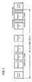
- Then, as a means for transmitting such a digital acoustic signal as it is, a format regulated by lEEE1394 is used for example. According to the format, a synchronizing signal (cycle start) is generated from, for example, reference apparatus at a constant cycle (125µs)as shown in FIG. 6. Between the synchronizing signals, an arbitrary number of signal channels (1 to n) called an isochronous (synchronous) packet are provided.
- The isochronous packet has a structure, e.g. as shown in A of FIG. 7. The first row of the packet is one quadlet (4 bites = 32 bits). For the
first half 2 bytes in the first row of the packet is provided a value (data length) indicating a length of the subsequent area. Also, for the latter half 2 bytes in the first row are provided a value (tag) showing a format of the packet, a value (channel) showing a channel number, a value (tcode) to identify the packet, a value (sy) used for synchronization and so on. - That is, the first row of the isochronous packet is made a header area wherein information on various kinds of controls is provided. Further, in the second row is provided an error correcting code (header CRC) for data on the above-mentioned header area in the first row. Then, in and after the third row of the isochronous packet is provided data on a digital acoustic signal to be transmitted and the like over the range shown in the above-mentioned value (data length). Also, in the last row of the packet is provided an error correcting code (data CRC) for data transmitted in and after the third row.
- Moreover, a section for transmitting such as control information and the like called an asynchronous (nonsynchronous) packet is provided in a remaining period after the isochronous packet (the minimum amount is secured) between on the above synchronizing signals (cycle start). Then, in accordance with control information transmitted via the asynchronous packet, transmission of the digital acoustic signal and the like is carried out between arbitrary apparatuses using some channel of the above-mentioned asynchronous packet.
- In B of FIG. 7 is shown a structure of the asynchronous packet where controlling information (data) of, for example, one quadlet is written into a desired memory or register of the arbitrary apparatus. The first row of the packet is one quadlet and for the
first half 2 bytes in the first row is provided an identifying code of a destination (addressee) apparatus (destination ID). Also, for thefirst half 2 bytes in the second row is provided an identifying code of a sending apparatus (source ID). Meanwhile, these identifying codes are beforehand set for each of apparatuses for example, at a time of constructing a system. - For the
latter half 2 bytes in the first row are provided a label (tl) for showing a series of controlled states (transaction), a code (rt) for showing a status of retransmission, a value (tcode) for distinguishing the packet and a value (pri) for showing order of priority. Further, for the latter half 2 bytes in the second row and in the third row are provided addresses of a memory of the destination and the like (destination offset). Data of 4 bytes to be written is provided in the fourth row. Then, in the fifth row is provided error correcting codes (header CRC) for each of data in the first to fourth rows. - Furthermore, in C of FIG. 7 is shown a structure of the synchronizing signal (cycle start). The synchronizing signal is also transmitted with the structure of the asynchronous packet. The first and third rows of this packet are the same as those of another asynchronous packet. However, with the packet of synchronizing signal, all apparatuses are designated by the destination identifying code in the
first half 2 bytes in the first row. The sender identifying code of thefirst half 2 bytes in the second row provides that of the reference apparatus. - In the fourth row of the packet is provided a cycle time code (a value of a timer register provided in the reference apparatus). Further, in the fifth row is provided an error correcting code (header CRC) for each of data in the first to fourth rows. By the way, in the asynchronous packet are defined some forms other than this such as a writing, a read-out request and a read-out response for data of 1 quadlet or more but they are not relevant to this application and thus are not described.
- Therefore, by using such a transmission format, it is possible for a bus line to connect between, for example, the above-mentioned DVD player or the like and the acoustic apparatus of other digital formats or the like. Thus, mutual control is carried out between these apparatuses using the control information transmitted by way of the above-mentioned asynchronous packet. This control enables mutual transmission of data such as an arbitrary digital acoustic signal and the like by using some channel of the above-mentioned asynchronous packet between these apparatuses.
- However, in such a transmission format, for example, a sampling frequency of a digital acoustic signal is such that one frequency is determined corresponding to a signal of one system. Therefore, when there are a main acoustic signal at, a sampling frequency of 96kHz and a sub-acoustic signal at a sampling frequency of 48kHz as the above-mentioned DVD audio recording signal, it has been impossible to transmit these signals collectively (en bloc) on the conventional format.
- Then, when these signals are transmitted on the conventional format, it is conceivable that the sub-acoustic signal at a sampling frequency of 48kHz is doubled by a prior value holding or the like and is transmitted twice at a timing rate of the sampling frequency of 96kHz. However, with this method, data to be transmitted becomes redundant with a resultant degradation in data transmission efficiency by the whole bus. It is also conceivable that the system is divided according to, for example, sampling frequency, but there then arises a necessity to provide a reproducing means for each system, and also a necessity to maintain synchronization among respective systems, which makes an apparatus complicated.
- Thus the conventional transmission format has made it impossible to transmit signals sampled at different sampling frequencies en bloc and when such signals are to be transmitted, there has been a fear that data transmission efficiency is degraded and the apparatus becomes complicated.
- Therefore, the present invention is such that, for sample data at different sampling frequencies, data generated during one of the sampling periods is collected together to form a data block and at the same time, data of the number of sample data generated during the sampling period is added thereto. This makes it possible to transmit en bloc signals at different sampling frequencies as well as to easily reconstruct and restore these sample data.
- To allow better understanding an embodiment of the present invention will be described by way of non-limitative example with reference to the drawings in which:
- FIG. 1 is a diagram for describing IEEE1394;
- FIG. 2A∼C is a diagram for describing transmitting packets;
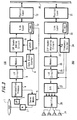
- FIG. 3 is a block diagram of one embodiment of a sample data transmitting apparatus according to the present invention;
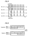
- FIG. 4 is a diagram for describing the operations of the same;
- FIG. 5 is a diagram for describing operations of the same;
- FIG. 6 is a diagram for describing an isochronous packet to which the present invention is applied; and
- FIG. 7 is a diagram for describing its operation.
-
- Specifically, the first embodiment according to the present invention is a sample data transmitting method of transmitting a first sample data sampled at a first sampling frequency and a second sample data sampled at a second sampling frequency higher than the first sampling frequency, in which the transmission is carried out by collecting together the first and second sample data generated during a sampling period of the first sampling frequency into a data block and by adding data of the number corresponding to the number of sample data generated during the sampling period of the first sampling frequency to the second sample data. As a result, it is possible to transmit en bloc signals sampled at different sampling frequencies as well as to easily reconstruct and restore these sample data.
- The second embodiment according to the present invention is a sample data receiving method of receiving a transmitted signal comprising a first sample data sampled at a first sampling frequency and a second sample data sampled at a second sampling frequency higher than the first sampling frequency, and in which the first and second sample data generated during a sampling period of the first sampling frequency are collected together to form a data block, and data of the number corresponding to the number of sample data generated during the sampling period of the first sampling frequency is added to the second sample data. The reception is carried out by forming a first clock signal of the first sampling frequency as well as forming a second clock signal of the second sampling frequency from the first clock signal and at the same time, discriminating of the number data corresponding to the number of sample data, added to the second sample data, generated during the sampling period of the first sampling frequency, for reconstructing a data sequence of the second sample data. As a result, it is possible to transmit en bloc signals by different sampling frequencies as well as to easily reconstruct and restore these sample data.
- Further, the third embodiment according to the present invention is a sample data transmission method of transmitting a first sample data sampled by a first sampling frequency and a second sample data sampled by a second sampling frequency higher than the first sampling frequency, in which: the transmission side collects together that the first and second sample data generated during a sampling period of the first sampling frequency to form a data block and adds data of the number corresponding to the number of sample data generated during the sampling period of the first sampling frequency to the second sample data; for transmission and the receiving side forms a first clock signal of the first sampling frequency as well as forms a second clock signal of the second sampling frequency by multiplying the first clock signal and at the same time, discriminates data of the number corresponding to the number of sample data, added to the second sample data, which are generated during the sampling period of the first sampling frequency to reconstruct the second sample data for reception. As a result, it is possible to transmit en bloc signals by different sampling frequencies as well as to easily reconstruct and restore these sample data.
- Also, the fourth embodiment according to the present invention is a sample data transmitting apparatus for transmitting a first sample data sampled at a first sampling frequency and a second sample data sampled at a second sampling frequency higher than the first sampling frequency, comprising means for forming en bloc the first and second sample data generated during a sampling period of the first sampling frequency into a data block and means for adding data of the number corresponding to the number of sample data generated during the sampling period of the first sampling frequency to the second sample data. As a result it is possible to transmit en bloc signals at different sampling frequencies as well as to easily reconstruct and restore these sample data.
- Further, the fifth embodiment according to the present invention is a sample data receiving apparatus for receiving a transmitted signal comprising a first sample data sampled by the first sampling frequency and a second sample data sampled by a second sampling frequency higher than the first sampling frequency, and in which: the first and second sample data generated during a sampling period of the first sampling frequency are formed collectively into a data block; and data of the number corresponding to the number of sample data generated during the sampling period of the first sampling frequency is added to the second sample data. It comprises means for forming a first clock signal of the first sampling frequency, means for forming a second clock signal of the second sampling frequency from the first clock signal, and means for discriminating data of the number corresponding to the number of the sample data generated during the sampling period of the first sampling frequency, which are added to the second sample data, to reconstruct the data sequence of the second sample data for reception. As a result it is possible to transmit en bloc signals by different sampling frequencies as well as to easily reconstruct and restore these sample data.
- Also, the sixth embodiment according to the present invention is a sample data transmission apparatus for transmitting a first sample data sampled at a first sampling frequency and a second sample data sampled at a second sampling frequency higher than the first sampling frequency, comprising: means to collect together the first and second sample data generated during a sampling period of the first sampling frequency to form a data block, means for adding data of the number corresponding to the number of sample data generated during the sampling period of the first sampling frequency to the second sample data for transmission; and means for forming a first clock signal of the first sampling frequency as well as forming a second clock signal of the second sampling frequency by multiplying the first clock signal and discriminating data of the number corresponding to the number of sample data, added to the second sample data, generated during the sampling period of the first sampling frequency to reconstruct the second sample data for reception. As a result, it is possible to transmit en bloc signals at different sampling frequencies as well as to easily reconstruct and restore these sample data.
- The embodiments of the present invention will be described below with reference to the drawings. FIG. 1 is a block diagram showing the whole structure of a system to which the sample data transmitting method, receiving method, transmission method, and its transmitting apparatus, receiving apparatus, transmission apparatus according to the present invention are applied.
- Referring to FIG. 1, in a transmitting
apparatus 100 is provided adikc 1 as a recording medium of a digitized acoustic signal such as DVD audio and the like to which, for example, a DVD-ROM (Read-Only-Memory) is applied. Thisdisc 1 is rotated by amotor 2 and from a recording surface of the rotateddisc 1 is derived a recorded signal through anoptical pickup 3. Then, the derived signal is supplied to areproduction processing apparatus 4 and a digital acoustic signal according to a format of the above-mentioned DVD audio is reproduced. - Specifically, in the above-mentioned DVD audio format, a total of 4 channels comprising 2 channels for sample data with the sampling frequency of 96kHz and the quantized bit number of 24 bits for, for example, a main acoustic signal and 2 channels for sample data with the sampling frequency of 48kHz and the quantized bit number of 16 bits for, for example, a sub-acoustic signal such as surround or the like are recorded and these recorded digital acoustic signals are reproduced.
- Meanwhile, a synchronizing signal detected together with the acoustic signal in the above-mentioned
reproduction processing apparatus 4 is supplied to a servo means 5 for driving themotor 2. Then, the above-mentioned synchronizing signal is compared with a reference clock signal from, for example, an interior timer described below in the servo means 5 and in order for these timing to have predetermined relations, revolution of themotor 2 is servo-controlled. As a result, thedisc 1 connected to themotor 2 is rotated at a predetermined revolution speed for reproducing, for example, the digitized acoustic signal. - Further, the digitized acoustic signal reproduced by the above-mentioned
reproduction processing apparatus 4 is supplied to a memory 7 through an interface (I/F)circuit 6. Then, in the memory 7, for example, a total of 6 sample data comprising 4 pieces of sample data for 2 channels × 2 samplings, a sampling frequency of 96kHz and the quantized bit number of 24 bits and 2 pieces of sample data for 2 channels, a sampling frequency of 48kHz and the quantized bit number of 16 bits are formed into one data block. - To be specific, as mentioned above, the sample data of a left channel (Main, Lch) and a right channel (Main, Rch) of the main acoustic signal are formed by a sampling frequency of 96kHz and the sample data of a left channel (Rear, Lch) and a right channel (Rear, Rch) of the sub-acoustic signal are formed by a sampling frequency of 48kHz. As a result, as shown in FIG. 2, the sample data of the main acoustic signal are formed twice that of the sub-acoustic signal.
- Then, in the above-mentioned
interface circuit 6 and the memory 7, as shown surrounding by a line in FIG. 2, out of these sample data, 6 pieces of the sample data being a sum of a total of 4 pieces (1, 2, 3, 4) of respective 2 pieces of the left channel and the right channel of the main acoustic signal and a total of 2 pieces (5, 6) of each one piece of the left channel and the right channel of the sub-acoustic signal are combined, for example, in order of illustrated numbers to form one data block. - Meanwhile, in a case where there are 2 serial interfaces for 96kHz sample data of 2 channels and 48kHz sample data of 2 channels between the
reproduction processing circuit 4 and theinterface circuit 6, as shown, for example, in the transmitting side of FIG. 3, 6 pieces of sample data consisting of 4 pieces of sample data from the 96kHz serial interface and 2 pieces of sample data from the 48kHz serial interface are combined to form one data block. - The thus formed data blocks are inputted in the memory 7. Here, the memory 7 is made to have a so-called first-infirst-out structure, wherein the inputted data blocks are outputted in the inputted order at predetermined timing. Then, the outputted datablocks are supplied to a CIP
heaeder adding circuit 8 described below. At the same time, the number of the data blocks inputted in the above-mentioned memory 7 is counted by ablock counter 9. - Further, the counted value from the
data block counter 9 and a reference time from a cycle timer provided at alink layer 10 for, e.g. a serial bus according to IEEE1394 described below are both supplied to alatch circuit 11. Then, a reference time from the cycle timer at a time when, for example, the 3 low order digits of the counted value (binary numeral) of the above-mentioneddata block counter 9 becomes [000] is latched and the latched reference time is supplied to theheader adding circuit 8. - Then, in the
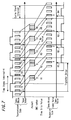
header adding circuit 8, headers provided, for example, in the third and fourth rows of the above-mentioned isochronous packet are formed as described below and the data block is provided as follows. In addition, the isochronous packet is formed in a constant cycle (125µs). Therefore, a plurality of the data blocks generated during the cycle (125µs). are provided in one isochronous packet. - Specifically, the structure of the isochronous packet formed is shown in FIG. 4. In this FIG. 4, one row of the packet is one quadlet (4 bytes = 32 bits). Prescribed headers formed in the
link layer 10 described below are provided in the first and second rows of the isochronous packet. Then, in the third and fourth rows following the first and second rows are provided the header describing about the data block transmitted on this packet. - In the first 2 bits in the third row of the isochronous packet is provided a value [00]. At the second one byte in the third row, is provided a counted value (DBS) of the
data block counter 9 when the first data block transmitted on the isochronous packet is formed. Further, at the fourth one byte is provided the next counted value (DBC) of thedata block counter 9 when the last data block transmitted on this isochronous packet is formed. - Also, in the first 2 bits in the fourth row of the isochronous packet is provided a value [10]. In the
last half 2 bytes in the fourth row is provided a reference time (time stamp data) value (SYT) from the cycle timer latched by the above-mentionedlatch circuit 11. Meanwhile, in the blank portions in the figure are provided other control data and the like, but since they have nothing to do with the application of the present invention, its description is omitted. In this manner, the predetermined CIP (Common lsochronous Packet) header is provided in the third and fourth rows of the ischronous packet. - Further, after the fifth row of the isochronous packet are provided the above-mentioned data blocks. Here, in FIG. 4, 4 pieces of sample data for the above-mentioned sampling frequency of 96kHz, the quantized bit number of 24 bits and 2 channels × 2 samplings as well as 2 pieces of sample data for the sampling frequency of 48kHz, the quantized bit number of 16 bits and 2 channels are provided in one row, respectively. At the same time, these 6 pieces (rows) of sample data are made into one data block, and a plurality of the data blocks generated during the above-mentioned cycle (125µs) are successively provided.
- In the fifth row is provided the first sample data of the left channel of the main acoustic signal of, for example, a sampling frequency of 96kHz, the quantized bit number of 24 bits (24-bit 96kHz, Main, Lch). Then, in the first 2 bits in the fifth row is provided a value [11] showing, for example, DVD audio and at the fourth bit is provided a flag [1] showing that the following sample data is data sampled by a twofold sampling frequency. Further, at the seventh and eighth bits is provided a value [00] showing that the quantized bit number of the succeeding sample data is 24 bits.
- Similarly, in the 6th row is provided the first sample data of the right channel of the main acoustic signal of, for example, a sampling frequency of 96kHz, the quantized bit number of 24 bits (24-bit, 96kHz, Main, Rch). Also, in the seventh row is provided the second sample data of the left channel of the main acoustic signal of a sampling frequency of 96kHz, hte quantized bit number of 24 bits (24-bit, 96kHz, Main, Lch) and in the eighth row is provided the second sample data of the right channel of the main acoustic signal of a sampling frequency of 96kHz, the quantized bit number of 24 bits (24-bit, 96kHz, Main, Rch).
- Further, in the ninth row is provided a sample data of the left channel of the sub-acoustic signal of, for example, a sampling frequency of 48kHz, the quantized bit number of 16 bits (16-bit, 48kHz, Rear, Lch). Then, in the first 2 bits in the ninth row is provided a value [11] showing, for example, DVD audio and at the fourth bit is provided a flag [0] showing that the succeeding sample data is data sampled by a basic sampling frequency. Further, at the seventh and eighth bits is provided a value [10] showing that the quantized bit number of the succeeding sample data is 16 bits.
- Similarly, in the tenth row is provided a sample data of the right channel of the sub-acoustic signal of, for example, a sampling frequency of 48kHz, the quantized number of 16 bits (16-bit, 48kHz, Rear, Rch). Then, these 6 pieces (rows) of sample data are made into one data block and a plurality of the data blocks generated during the above-mentioned cycle (125µs) are successively provided. In addition, although succeeding data blocks are omitted, rows of the same form are repeated. Further, in the last row of the packet is provided an error correction code (data CRC) for data transmitted on and after the third row.
- Data on and after the third row of the thus formed isochronous packet is supplied from adding the above-mentioned
CIP header circuit 8 to thelink layer 10 for the serial bus of the IEE1394. Then, in thelink layer 10 is generated the prescribed isochronous packet header which is provided in the first and second rows of the isochronous packet. That is to say, in thefirst half 2 bytes in the first row of the packet is provided a value (data length) showing a length of subsequent data area. - Also, in the
latter half 2 bytes in the first row of the packet are provided data such as a value (tag) showing a format of the packet, a value (channel) showing a predetermined channel number, a value (tcode) for identifying the packet, and a value (sy) used for synchronization to form the prescribed header. In this case, in the value (tag9 showing a format of the packet is provided a value indicating that CIP header is included in the subsequent data. Further, in the second row is provided an error correction code (header CRC) for the header area data in the above-mentioned first row. - The isochronous packet is formed in this manner. In FIG. 1, the thus formed isochronous packet is further supplied from the above-mentioned
link layer 10 to aphysical layer 12 for a serial bus of the IEEE1394. Then, from thephysical layer 12 is carried out transmission to theserial bus 20 at predetermined timing in accordance with a synchronizing signal (cycle start) and the like transmitted on, for example, the IEEE1394serial bus 20. - Further, the isochronous packet transmitted to the
serial bus 20 is supplied to alink layer 22 through, for example, aphysical layer 21 of a receivingapparatus 200 and a necessary packet is received by discriminating the above-mentioned value (channel) showing a channel number for example. Then, the received isochronous packet is supplied from thelink layer 22 to a CIPheader analyzing circuit 23 of and an analysis of the header provided, for example, in the third and fourth rows of the isochronous packet is carried out. - Specifically, as mentioned above, on the transmitting side, the reference time from the cycle timer at a time, for example, when the low three order digits of the counted value (binary numeral) of the
data block counter 9 becomes [000] is latched, and the latched reference time is transmitted as a value (SYT) of the CIP header. Also, the counted value (DBS) of thedata block counter 9 at a time when the first data block to be included in the isochronous packet is formed and the next counted value (DBC) of thedata block counter 9 when the last data block is formed are transferred on the CIP header. - At the CIP
header analysis circuit 23, by using the counted value (DBS) and the counted value (DBC), a data block when the three low order digits of the counted value (binary numeral) of thedata block counter 9 becomes [000] is identified. BY deriving the identified data block at a time corresponding to the value (SYT) of the reference time (time stamp data), the timing for deriving the data block can be synchronized. - These conditions will be described referring to FIG. 5. By the way, in the above-mentioned apparatus, 8 pieces of the data blocks are placed between respective times when the 3 low order digits of the counted value (binary numeral) of the
data block counter 9 become [000], but a case of placing 4 pieces is shown in FIG. 5 to simplify the description. - In the uppermost rank of this FIG. 5 is shown output of the data block counter and the output rises at every four pieces of generated data blocks shown in the next rank. Therefore, on the transmitting side, a diagonally shaded data block next to the rising edge of the output is a data block corresponding to the reference time (time stamp data). Also, timer values (T1, T2, ···) on this occasion become the reference time on the transmitting side.
- On the other hand, date blocks generated at a previous cycle start interval are collected to form the isochronous packet at each cycle start interval shown wholly by vertical lines. The counted value (DSB) of data block
counter 9 when the first data block is formed among them and the next counted value (DBS) of thedata block counter 9 when the last data block is formed are transmitted on the CIP header. - On the receiving side, the counted value (DBC) transmitted on a previously received isochronous packet is the counted value of the
data block counter 9 when the first data block of an isochronous packet currently received is formed, and a data block when the two lower order digits of the counted value become [00] after starting count from this counted value (DBC) becomes a diagonally shaded data block corresponding to the reference time (time stamp data) at intervals of four pieces of data blocks. - By taking out data blocks so that the diagonally shaded data blocks may coincide with timer values (R1, R2,···) on the receiving side, data blocks in synchronism with the reference time can be taken out. In addition, by previously setting the transmitted timer value of the reference time (time stamp data) on the transmitting side at shifted values (R1, R2···) in consideration of a time necessary for the transmission processing, synchronization with the timer values on the receiving side can be facilitated.
- Furthermore, by using the data block taken out in synchronism with the reference time, a clock signal at intervals (48kHz) wherein the above-mentioned data block is formed and a 96kHz clock signal which doubles this clock signal can be formed. Thus, in FIG. 3, by supplying a signal in synchroizm with data blocks derived from the CIP
header analyzing circuit 23 of to a phase lock (PLL)frequency dividing circuit 24, the above-mentioned clock signals of 48kHz and 96kHz can be formed. - The data blocks derived from the CIP
header analyzing circuit 23 are supplied to amemory 25 which is made a first-in first-out (FIFO) structure. Then the data blocks corresponding to, for example, the above-mentioned reference time (time stamp data) cen be taken out of thememory 25 at timing of the reference time by an interface (I/F)circuit 26 which is timing controlled by the above-mentioned clock signals of 48kHz and 96kHz.The subsequent data blocks thereto can be taken out sequentially in synchronism with the clock signals. - In other words, when the fourth bits in the fifth to eighth row is [1] in the above-mentioned isochronous packet, by making 24 bits sample data in the seventh and eight rows, digital acoustic signals are taken out every 96kHz clock signal. Also, when the fourth bits in the nineth and tenth rows is [0], a digital acoustic signal is obtained by taking out 16 bits sample data in each of ranks at every 48kHz clock signal.
- In this manner, respective digital acoustic signals induding a left channel (24-bit, 96kHz, Main, Lch) and a right channel (24-bit, 96kHz, Main, Rch) of a main acoustic signal of, for example, a sampling frequency of 96kHz, the quantized bit number of 24 bits, and a left channel (16-bit, 48kHz, Rear, Lch) and a right channel (16-bit, 48kHz, Rear, Rch) of a sub-acoustic signal of a sampling frequency of 48kHz, the quantized bit number of 16 bits can be brought out.
- Meanwhile, when an interval between the
interface circuit 26 and subsequent circuits there are 2 pieces of serial interfaces of, for example, 96kHz sample data of 2 channels and 46kHz sample data of 2 channels, as shown on the receiving side in FIG. 5, four pieces of sample data of the left and right channels of the main acoustic signal are brought to a 96kHz serial interface and two pieces of sample data of the left and right channels of a sub-acoustic signal are brought to a 48kHz serial interface so that respective digital acoustic signals may be brought out. - These digital acoustic signals are further supplied to a D/
A converting circuit 27, respectively. In this case, the sample data of a sampling frequency of 48kHz can be put into analog data by a D/A converter of 96 kHz by using the same value twice at a time by, for example, holding a previous value. Also, the sample data of the quantized bit number of 16 bits can be put into analog data by a 24 bit D/A converter which makes its value high order. Then the above-mentioned D/A convertingcircuit 27 can now be implemented by using, for example, the 24 bit and 96kHz D/A converter. - The acoustic signals D/A converted by the D/
A converting circuit 27 are supplied to aspeakers group 4 through anoutput amplifier 28. Consequently, digital acoustic signals derived from a recording medium (disc 1) of DVD audio or the like including: left and right channels of a main acoustic signal of, for example, a sampling frequency of 96kHz and the quantized bit number of 24 bits; and of left and right channels of the sub-acoustic signal of sampling frequency of 48kHz and the quantized bit number of 16 bits are transmitted through, for example, IEEE1394serial bus 20 and emitted from thespeakers group 24. - Therefore, according to the method and apparatus of the present invention,collecting together data generated during on of the sampling periods of sample data at different sampling frequencies to form a data block and adding data of the number of the sample data generated during that period, signals of different sampling frequencies can be transmitted in one lot and these sample data can easily be reconstructed and restored.
- As described above, there has been a fear that it is impossible to transmit collectively signals at different sampling frequencies on the conventional transmission format, and if such signals are to be transmitted, there incurs a deterioration in data transmitting efficiency as well as complexity of an apparatus. However, according to the present invention, these problems can easily be solved.
- Furthermore, according to the above-mentioned method and apparatus, by making a higher sampling frequency twice or a multiple of a lower sampling frequency, the number of sample data included in 1 data block on the side of the higher sampling frequency can be made a multiple of the number of sample data by the lower frequency, thus making it possible to easily form the data block. However, the relation between these sampling frequencies can be determined optionally.
- Moreover, in the above-mentioned method and apparatus, by adding time stamp data indicating a reference time at every prescribed number of data blocks for transmission, the receiving side can easily achieve synchronization of data blocks and easily generate a clock signal and the like for D/A conversion by using the data blocks.
- Furthermore, by causing two or more pieces of the data blocks to which the time stamp data is added not to be included in a plurality thereof transmitted en bloc, the synchronization of data blocks by the time stamp data can be further facilitated. Additionally, by shifting the time stamp data beforehand in view of a time required for a transmission processing, the synchronization of data blocks by the time stamp data can be still more facilitated.
- Furthermore, by taking out data blocks on and after a specified data block, based on the time stamp data and an internal clock, it becomes possible to smoothly take out the data blocks. Also, by forming clock signals of a first and second sample frequencies based on the time stamp data and the internal clock, formation of the clock signal can be done easily carried out.
- It is noted that the present invention is not limited to the embodiments described above, and various kinds of modifications can be effected without departing from the spirit of the present invention.
- Thereafter, according to the invention in
Claim 1, by collecting together data generated during a sampling period of one of sample data by different sampling frequencies to form a data block and adding data of the number of the sample data generated during the period, transmission of sample data can be carried out so that signals of different sampling frequencies can be transmitted en bloc and these sample data can easily be reconstructed and restored. - While there has been a fear that it is impossible to transmit en bloc signals at different sampling frequencies on the conventional transmission format, and if such signals are to be transmitted, there incurs a deterioration in data transmitting efficiency as well as complexity of an apparatus, these problems can easily be solved according to the present invention.
- Furthermore, according to the invention in
Claim 2, by making a higher sampling frequency twice or a multiple of a lower sampling frequency, the number of sample data included in one data block on the side of the higher sampling frequency can be made a multiple of the number of sample data by of the lower sampling frequency, thus making it possible to easily form the data block. - Furthermore, according to the invention in
Claim 3, by adding time stamp data indicating a reference time at every prescribed number of data blocks for transmission, the receiving side can easily achieve synchronization of data blocks and easily further out occurrence of a clock signal and the like for D/A conversion by using the data blocks. - In addition, according to the invention in
Claim 4, by causing two or more pieces of the data blocks to which the time stamp data is added not to be included in a plurality thereof transmitted en bloc, the synchronization of data blocks by the time stamp data can be further facilitated. - Also, according to the invention in
Claim 5, by providing time stamp data with a shifted value beforehand in of a time required for a transmission processing, the synchronization of the data blocks by the time stamp data can be still more facilitated. - Furthermore, according to the invention in
Claim 6, by collecting together data generated during one of the sampling period of sample data different sampling frequencies to form a data block and adding data of the number of the sample data generated during the period, reception of sample data can be carried out so that signals of different sampling frequencies can be transmitted collectively and these sample data can easily be reconstructed and restored. - Furthermore, according to the invention in Claim 7, by making a higher sampling frequency two times or multiple of a lower sampling frequency, the number of data included in 1 data block on the side of the higher sampling frequency can be made a multiple of the number of sample data by the lower sampling frequency, thus making it possible to easily form the data block.
- Furthermore, according to the invention in
Claim 8, by adding time stamp data indicating a reference time at every prescribed number of data blocks for transmission, the receiving side can easily achieve synchronization of data blocks and further, easily generate of a clock signal and the like for D/A conversion by using the data blocks. - Moreover, according to the invention in
Claim 9, by causing more than two or more pieces of the data blocks to which the time stamp data is added not to be included in a plurality thereof transmitted en bloc, the synchronization of data blocks by time stamp data can be further facilitated. - Further, according to the invention in
Claim 10, by taking out data blocks on and after a specified data block, based on the time stamp data and an internal clock, it becomes possible to smoothly take out the data blocks. - Furthermore, according to the invention in
Claim 11, by forming clock signals of a first and second sampling frequencies based on the time stamp data and the internal clock, formation of the clock signal can be done easily carried out. - In addition, according to the invention in
Claim 12, by collecting together data generated during one of the sampling periods of sample data by different sampling frequencies to form a data block and adding data of on the number of the sample data generated during that period, transmission of sample data can be carried out so that signals of different sampling frequencies can be transmitted en bloc and these sample data can easily be reconstructed and restored. - Also, according to the invention in
Claim 13, by making a higher sampling frequency twice or a multiple of a lower sampling frequency, the number of sample data included in one data block by the higher sampling frequency can be made a multiple of the number of sample data by the lower sampling frequency, thus making it possible to easily form the data block. - Further, according to the invention in Claim 14, by adding time stamp data indicating a reference time at every prescribed number of data blocks, the receiving side can easily achieve synchronization of data blocks and further easily generate of a clock signal and the like for D/A conversion by using the data blocks,.
- Furthermore, according to the invention in Claim 15, by causing two or more pieces of the data blocks to which the time stamp data is added not included in a plurality thereof transmitted en bloc, the synchronization of data blocks by the time stamp data can be further facilitated.
- In addition, according to the invention in
Claim 16, by providing time stamp data with a value shifted beforehand in view of a time required for a transmission processing, the synchronization of the data blocks by the time stamp data can be facilitated. - Furthermore, according to the invention in Claim 17, by making a higher sampling frequency twice or multiple of a lower sampling frequency, the number of sample data included in one data block by the higher sampling frequency can be made a multiple of the number of sample data by the lower sampling frequency, thus making it possible to easily form the data block.
- Furthermore, according to the invention in Claim 18, by adding time stamp data indicating a reference time at every prescribed number of data blocks for transmission, the receiving side can easily achieve synchronization of data blocks and further easily generate of a clock signal and the like for D/A conversion by using the data blocks.
- Moreover, according to the invention in Claim 19, by causing two or more pieces of the data blocks to which the time stamp data is added not included in a plurality thereof transmitted en bloc, the synchronization of data blocks by the time stamp data can be further facilitated.
- Further, according to the invention in
Claim 20, by taking out data blocks after specified data blocks, based on the time stamp data and an internal clock, it becomes possible to smoothly take out the data blocks. - Furthermore, according to the invention in
Claim 21, by forming clock signals of a first and second sampling frequencies based on the time stamp data and the internal clock, formation of the clock signal can be easily carried out. - In addition, according to the invention in
Claim 22, by collecting together data generated during a sampling period of one of sample data at different sampling frequencies to form a data block and adding data of the number of the sample data generated during that period, it is possible to implement an apparatus for transmitting sample data so that signals of different sampling frequencies can be transmitted collectively and these sample data can easily be reconstructed and restored. - Also, according to the invention in
Claim 23, by making a higher sampling frequency twice or a multiple of a lower sampling frequency, the number of sample data included in 1 data block on the side of the higher frequency can be made multiple-times the number of data on the side of the lower frequency, thereby making it possible to easily form a data block. - Furthermore, according to the invention in
Claim 24, by adding time stamp data indicating a reference time at every prescribed number of data blocks, the receiving side can easily obtain synchronization of data blocks and by further using the data blocks, further easily generate of a clock signal and the like for D/A conversion. - Furthermore, according to the invention in
Claim 25, by causing two or more pieces of the data blocks to which the time stamp data is added not to be included in the plurality thereof numbers transmitted en bloc, the synchronization of data blocks by time stamp data can be further facilitated. - In addition, according to the invention in
Claim 26, by providing time stamp data with a value shifted beforehand in consideration of a time required for a transmitting process, synchronization of the data blocks by the time stamp data can be still more facilitated. - Moreover, according to the invention in
Claim 27, by collecting together data on one hand generated during a sampling period of one of sample data by different sampling frequencies to form a data block and adding data of the number of the sample data generated during that period, it is possible to implement an apparatus for receiving sample data so that signals of different sampling frequencies can be transmitted en bloc and these sample data can easily be reconstructed and restored. - Also, according to the invention in
Claim 28, by making a higher sampling frequency twice or multiple of a lower sampling frequency, the number of sample data included in one data block by the higher sampling frequency can be made a multiple of the number of sample data by the lower frequency, thus making it possible to easily form the data block. - Furthermore, according to the invention in Claim 29, by adding time stamp data indicating a reference time at every prescribed number of data blocks, the receiving side can easily achieve synchronization of data blocks and, easily generate of a clock signal and the like for D/A conversion by using the data blocks.
- Furthermore, according to the invention in Claim 30, by causing two or more pieces of the data blocks to which the time stamp data is added not to be included in a plurality thereof numbers transmitted en bloc, the synchronization of data blocks by the time stamp data can be further facilitated.
- Moreover, according to the invention in Claim 31, by taking out data blocks on and after a specified data block, based on the time stamp data and the internal clock, it becomes possible to smoothly take out the data blocks.
- Furthermore, according to the invention in Claim 32, by forming clock signals of a first and second sampling frequencies based on the time stamp data and the internal clock, formation of the clock signal can be done easily.
- In addition, according to the invention in Claim 33, by collecting together data generated during a sampling period sample data at different sampling frequencies to form of a data block and adding data of the number of the sample data generated during the period, it is possible to implement an apparatus for transmitting of sample data can be carried out so that signals at different sampling frequencies can be transmitted collectively and these sample data can easily be reconstructed and restored.
- Also, according to the invention in Claim 34, by making a higher sampling frequency twice or multiple of a lower sampling frequency, the number of sample data included in one data block at the higher sampling frequency can be made a multiple of the number of sample data on the side of the lower sampling frequency, thus making it possible to easily form the data block.
- Furthermore, according to the invention in
Claim 35, by attaching time stamp data indicating displays a reference time at every prescribed number of data blocks, the receiving side can easily achieve synchronization of data blocks and further easily generate of a clock signal and the like for D/A conversion by using the data blocks. - Furthermore, according to the invention in Claim 36, by causing two or more of the data blocks to which the time stamp data is added not to be included in a plurality thereof transmitted en bloc, the synchronization of data blocks by the time stamp data can be further facilitated.
- In addition, according to the invention in Claim 37, by providing time stamp data with a value shifted beforehand in consideration of a time required for a transmitting process, the synchronization of the data blocks by the time stamp data can be still more facilitated.
- Also, according to the invention in Claim 38, by making a higher sampling frequency two times or multiple of a lower sampling frequency, the number of sample data included in one data at the higher sampling frequency can be made a multiple of the number of sample data at the lower sampling frequency, thus making it possible to easily form the data block.
- Furthermore, according to the invention in Claim 39, by adding time stamp data indicating a reference time at every prescribed number of data blocks, the receiving side can easily achieve synchronization of data blocks and further easily generate of a clock signal and the like for D/A conversion by using the data blocks.
- In addition, according to the invention in Claim 40, by causing two or more of the data blocks to which the time stamp data is added not to be included a plurality thereof numbers transmitted en bloc, synchronization of data blocks by the time stamp data can be further facilitated.
- Further, according to the invention in Claim 41, by taking out data blocks on and after a specified data block, based on the time stamp data and an internal clock, it becomes possible to smoothly take out the data blocks.
- Furthermore, according to the invention in Claim 42, by forming clock signals of a first and second sampling frequencies based on the time stamp data and the internal clock, formation of the clock signal can be done easily.
- Having described preferred embodiments of the present invention with reference to the accompanying drawings, it is to be understood that the present invention is not limited to the above-mentioned embodiments and that various changes and modifications can be effected therein by one skilled in the art without departing from the spirit or scope of the present invention as defined in the appended claims.
Claims (42)
- A sample data transmitting method for transmitting a first sampling data sampled at a first sampling frequency and a second sampling data sampled at a second sampling frequency higher than said first sample frequency, comprisingan adding process for adding data corresponding to the number of sample data generated during a sampling period of said first sample frequency to said second sample data,a data block forming process for forming en bloc said first sample data generated during a sampling period of said first sample frequency and said second sampling data added with said data corresponding to the number of sample data generated during a sampling period of said first sample frequency into data blocks, anda data block transmitting process for transmitting said formed data blocks.
- A sample data transmitting method according to claim 1, wherein said second sampling frequency is a multiple one of said first frequency, and in said data block forming process, a predetermined number of first sample data and said multiple number of said second sample data are collected together to form a data block.
- A sample data transmitting method according to claim 1 or 2, further comprising a time stamp adding process for adding time stamp data indicating a reference time at every prescribed number of said data blocks.
- A sample data transmitting method according to claim 3, comprisinga process for collecting together said plurality of data blocks formed up to then each predetermined synchronous period, anda process for adding data based on the sequence of said data blocks in each of said synchronous period, andcarrying out signal transmission by making said prescribed numbers ones so that no less than 2 of said data blocks attached with said time stamp data are not included in said plurality of data blocks at said every synchronization period.
- A sample data transmitting method according to claim 3 or 4, wherein said time stamp data is provided with a value shifted beforehand taking into account a time necessary for a transmission processing.
- A sample data receiving method for receiving a transmitted signal consisting of a first sample data sampled at a first sampling frequency and a second sample data sampled at a second sample frequency higher than said first sampling frequency, and in whichsaid first and second sample data generated during a sampling period of said first sampling frequency are collected together to form a data block, and data of the number corresponding to the number of the sample data generated during the sampling period of said first sampling frequency is added to said second sample data for transmission, comprisinga process for forming a first clock signal of said first sampling frequency,a process for forming a second clock signal of said second sampling frequency from said first clock signal, anda reconstructing process for reconstructing a data row of said second sample data by discriminating data of the number corresponding to the number of the sample data generated during the sampling period of said first sampling frequency which is added to said second sampling data.
- A sample data receiving method according to claim 6, in whichsaid second sampling frequency is defined as a multiple of said first sampling frequency; and the data block formed by collecting a predetermined number of said first sample data and said multiple number of said second sample data are received; andthe second clock signal of said second sample frequency is formed by multiplying said first clock signal; andsaid second sample data are sequentially arranged to reconstruct a data sequence of said second sample data.
- A sample data receiving method according to claim 6 or 7, in whichtime stamp data indicating a reference time is added to said received data block at every prescribed number of said data blocks andperforming a signal reception processing based on said time stamp data.
- A sample data receiving method according to claim 8, receiving a signal wherein; a plurality of said data blocks formed up to then in each predetermined synchronous period are collected together; and data based on the sequence of said data blocks is added in each of said synchronous period; and said prescribed number is made such number that two or more of said data blocks to which said time stamp data is added are not included in said plurality of data blocks collected in each of said every synchronous period, and
specifying said data block to which said time stamp data based on the sequence of said data blocks is added and performing the reception process base on said time stamp data. - A sample data receiving method according to claim 8 or 9, in which
data blocks on and after said specified data blocks based on said time stamp data and an internal clock are taken out. - A sample data receiving method according to any one of claims 8 to 10, in which clock signals of said first and second sampling frequencies based on said time stamp data and the internal clock are formed.
- A sample data transmission and reception method for transmitting a first sample data sampled at a first sampling frequency and a second sample data sampled at a second sampling frequency higher than said first sampling frequency, in whichthe transmitting side collects together said first and second sample data generated during a sampling period of said first sampling frequency to form a data block, adds data of the number corresponding to the number of the sample data generated during the sampling period of said first sampling frequency to said second sample data for transmission andthe receiving side forms a first clock signal of said first sampling frequency, forms a second clock signal of said second sampling frequency by multiplying said first clock signal, and discriminating data of the number corresponding to the number of sample data generated during the sampling period of said first sampling frequency which is added to said second sample data to reconstruct said second sample data for reception.
- A sample data transmission and reception method according to claim 12, in which said second sampling frequency is defined as a multiple ofsaid first sampling frequency, anda predetermined number of said first sample data and said multiple number of said second sample data are collected together to form a data block.
- A sample data transmission and reception method according to claim 12 or 13, in which time stamp data indicating a reference time at every prescribed number of said data blocks is added for transmission.
- A sample data transmission and reception method according to claim 14, collecting together a plurality of said data blocks formed up to then in each predetermined synchronous period,adding data based on the sequence of said data blocks to said data blocks in each of said synchronous period andmaking said prescribed numbers to be such number that two or more of said data blocks to which said time stamp data is added are not included in said plurality of data blocks in each of said synchronous period.
- A sample data transmission and reception method according to claim 14 or 15, in which said time stamp data is provided with a value shifted by beforehand taking into account a time required for a transmission processing.
- A sample data transmission and reception method according to any one of claims 12 to 16, further comprising:defining said second sampling frequency as a multiple of said first sampling frequency,receiving data block formed by collecting a predetermined number of said first sample data and said multiple number of said second sample data,multiplying said first clock signal to form a second clock signal of said second sampling frequency, andsequentially arranging said second sample data to reconstruct a data row of said second sample data.
- A sample data transmission and reception method as claimed in any one of claims 12 to 17, further comprising:receiving said data blocks to which time stamp data indicating a reference time is added at every prescribed number of data blocks, and performinga reception process based on said time stamp data.
- A sample data transmission and reception method according to claim 18, further comprising:receiving a signal wherein; a plurality of said data blocks formed up to then in each predetermined synchronous period are collected together; data based on the sequence of said data blocks is added in each of said synchronous period; and said predetermined number is made to be such number that two or more of said data blocks to which said time stamp data is added are not included in said plurality of data blocks in each of said synchronous period, andspecifying said data blocks to which said time stamp data based on the sequence of said data blocks is added and performing the reception processing based on said time stamp data.
- A sample data transmission and reception method according to claim 18, further comprising taking out data blocks on and after said specified data block based on said time stamp data and an internal clock.
- A sample data transmission and reception method according to claim 18, further comprising forming clock signals of said first and second sampling frequencies based on said time stamp data and the internal clock.
- A sample data transmitting apparatus for transmitting a first sample data sampled at a first sampling frequency and a second sample data sampled by a second sampling frequency higher than said first frequency, comprisingmeans for collecting said first and second sample data generated during a sampling period of said first sampling frequency to form a data block, andmeans for adding data of the number corresponding to the number of sample data generated during the sampling period of said first sampling frequency to said second sample data.
- A sample data transmitting apparatus as claimed in claim 22,in which said second sampling frequency is defined as a multiple of said first sampling frequency, andmeans for collecting a predetermined number of said first sample data and said multiple number of said second sample data to form a data block is provided.
- A sample data transmitting apparatus according to claim 22 or 23, comprising
adding means for adding time stamp data indicating a reference time at every prescribed number of said data blocks. - A sample data transmitting apparatus as claimed in claim 24, comprisingmeans for collecting together said plurality of said data blocks formed up to then in each predetermined synchronous period,means for adding data based on the sequence of said data blocks in each of said every synchronous period, andmeans for making said prescribed numbers to be such number that two or more of said data blocks to which said time stamp data is added are not included in said plurality of data blocks in each of said synchronous period for transmission.
- A sample data transmitting apparatus according to claim 24 or 25, comprising
means for providing said time stamp data with a value shifted by beforehand taking into account a time required for a transmission processing. - A sample data receiving apparatus for receiving a transmitted signal consisting ofa first sample data sampled at a first sampling frequency and a second sample data sampled at a second sampling frequency higher than said first sampling frequency, and in whichsaid first and second sample data generated during a sampling period for said first sampling frequency are collected to form a data block, and data of the number corresponding to the number of the sample data generated during the sampling period of said first sampling frequency are added to said second sample data for transmission, comprisingmeans for forming a first clock signal of said first sampling frequency,means for forming a second clock signal of said second sample frequency from said first clock signal, andmeans for discriminating data of the number corresponding to the number of the sample data generated during the sampling period of said first sampling frequency, added to said second sampling data to reconstruct a data row of said second sample data for reception.
- A sample data receiving apparatus according to claim 27, in whichsaid second sampling frequency is defined as a multiple of said first sampling frequency, comprisingmeans for receiving the data block formed by collecting together a predetermined number of said first sample data and said multiple number of said second sample data,means for forming the second clock signal of said second sampling frequency by multiplying said first clock signal, andmeans for reconstructing data sequence of said second sample data by sequentially arranging said second sample data.
- A sample data receiving apparatus according to claim 27 or 28, comprisingmeans for receiving a signal wherein; a plurality of said data blocks formed up to then in each predetermined synchronous period are collected together; and data based on the sequence of said data blocks are added in each of said synchronous period; and said prescribed number is made to be such number that two or more of said data blocks to which said time stamp data is added are not included in said plurality of data blocks in each of said synchronous period, andmeans for specifying said data blocks to which said time data is added in accordance with data blocks to perform a reception processing based on said time stamp data.
- A sample data receiving apparatus according to any one of claims 27 to 29, comprisingmeans for receiving said data block to which time stamp data indicating a reference time at every prescribed number of data blocks, andmeans for performing a signal reception processing based on said time stamp data.
- A sample data receiving apparatus according to claim 30, comprising
means for taking out data blocks on and after said specified data blocks based on said time stamp data and an internal clock. - A sample data receiving apparatus according to claim 30 or 31, comprising
means for forming clock signals of said first and second frequencies based on said time stamp data and the internal clock. - A sample data transmission and reception apparatus for transmitting a first sample data sampled at the first sampling frequency and a second sample data sampled at the second sampling frequency higher than said first sampling frequency, comprisingmeans for transmitting data blocks formed by collecting together said first and second sample data generated during a sampling period of said first sampling frequency, by adding data of the number corresponding to the number of the sample data generated during the sampling period of said first sampling frequency to said second sample data, andmeans for receiving by forming the first clock signal of said first sampling frequency, forming the second clock signal of said second sampling frequency by multiplying said first clock signal, and by discriminating said second sample data of the number corresponding to the number of the sample data, added to said second sample data, generated during the sampling period of said first sampling frequency to reconstruct said second sample data.
- A sample data transmission and reception apparatus according to claim 33, in whichsaid second sampling frequency is defined as a multiple of said first sampling frequency, andmeans for collecting together a predetermined number of said first sample data and said multiple number of said second sample data to form a data block is provided.
- A sample data transmission and reception apparatus according to claim 33 or 34, comprising means for adding time stamp data indicating a reference time at every prescribed number of data blocks for transmission.
- A sample data transmission and reception apparatus according to claim 35, comprisingmeans for collecting together said plurality of said data blocks formed up to then in each predetermined synchronous period,means for adding data based on the sequence of said data blocks in each of said every synchronous period, andmeans for making said prescribed numbers to be such number that two or more of said data blocks to which said time stamp data is added are not included in said plurality of data blocks in each of said synchronous period for transmission.
- A sample data transmission and reception apparatus according to claim 35 or 36, comprising
means for providing said time stamp data with a value shifted by beforehand taking into account time required for a transmission processing. - A sample data transmission and reception apparatus according to any one of claims 35 to 37, in whichsaid second sampling frequency is defined as a multiple of said first sampling frequency, comprisingmeans for receiving data blocks formed by collecting together a predetermined number of said first sample data and said multiple number of said second sample data, andmeans for forming a second clock signal of said second sampling frequency by multiplying said first clock signal, andmeans for reconstructing data sequence of said second sample data by sequentially arranging said second sample data.
- A sample data transmission and reception apparatus according to any one of claims 35 to 38, comprisingmeans for receiving said data blocks to which time stamp data indicating a reference time is added at every prescribed number of data blocks, andmeans for performing a reception processing based on said time stamp data.
- A sample data transmission and reception apparatus according to claim 39, comprisingmeans for receiving a signal wherein; a plurality of said data blocks formed up to then are collected together in each of predetermined synchronous period, and data based on the sequence of said data blocks are added in each of synchronous period, and said prescribed number is made to be such number that two or more of said data blocks to which said time stamp data is added are not included in said plurality of data blocks in each of said synchronous period, andmeans for specifying said data blocks to which said time stamp data is added in accordance with data based on the sequence of said data blocks, and performing a reception processing based on said time stamp data.
- A sample data transmission and reception apparatus according to claims 39 or 40, comprising
means for taking out data blocks on and after said specified data block based on said time stamp data and an internal clock. - A sample data transmitting apparatus according to any one of claims 39 to 41, comprising
means for forming clock signals of said first and second sampling frequencies based on said time stamp data and the internal clock.
Applications Claiming Priority (2)
| Application Number | Priority Date | Filing Date | Title |
|---|---|---|---|
| JP4869899 | 1999-02-25 | ||
| JP11048698A JP2000253091A (en) | 1999-02-25 | 1999-02-25 | Method for transferring, receiving and transmitting sample data, transfer device, receiver and transmitter for the sample data |
Publications (2)
| Publication Number | Publication Date |
|---|---|
| EP1031981A2 true EP1031981A2 (en) | 2000-08-30 |
| EP1031981A3 EP1031981A3 (en) | 2001-11-07 |
Family
ID=12810540
Family Applications (1)
| Application Number | Title | Priority Date | Filing Date |
|---|---|---|---|
| EP00301511A Withdrawn EP1031981A3 (en) | 1999-02-25 | 2000-02-25 | Data transmission |
Country Status (6)
| Country | Link |
|---|---|
| US (1) | US6807233B1 (en) |
| EP (1) | EP1031981A3 (en) |
| JP (1) | JP2000253091A (en) |
| KR (1) | KR20000058184A (en) |
| CN (1) | CN1216479C (en) |
| TW (1) | TW462171B (en) |
Cited By (2)
| Publication number | Priority date | Publication date | Assignee | Title |
|---|---|---|---|---|
| EP1407552A1 (en) * | 2001-05-24 | 2004-04-14 | Cirrus Logic, Inc. | Apparatus and method for multi-channel digital to analog conversion of signals with different sample rates |
| CN111046632A (en) * | 2019-11-29 | 2020-04-21 | 智器云南京信息科技有限公司 | Data extraction and conversion method, system, storage medium and electronic equipment |
Families Citing this family (3)
| Publication number | Priority date | Publication date | Assignee | Title |
|---|---|---|---|---|
| KR100574938B1 (en) * | 2003-02-20 | 2006-04-28 | 삼성전자주식회사 | Data recovery apparatus and method of decreasing data recovery error in high speed serial link |
| JP4301270B2 (en) * | 2006-09-07 | 2009-07-22 | ヤマハ株式会社 | Audio playback apparatus and audio playback method |
| JP5488317B2 (en) * | 2010-08-04 | 2014-05-14 | 富士通株式会社 | Monitoring system, apparatus, monitoring method and monitoring program |
Citations (5)
| Publication number | Priority date | Publication date | Assignee | Title |
|---|---|---|---|---|
| DE4223477A1 (en) * | 1992-07-16 | 1994-01-20 | Siemens Ag | Connecting through different rate data signals via time coupled field - reading transport module data into one memory and reads data out from two memories to couple data signals inserted in tributary units |
| EP0762684A2 (en) * | 1995-08-12 | 1997-03-12 | Sony Corporation | Data transmission method for digital audio signals |
| EP0838926A2 (en) * | 1996-10-22 | 1998-04-29 | Sony Corporation | Apparatus and method for transmitting and receiving isochronous data |
| EP0877370A1 (en) * | 1997-05-05 | 1998-11-11 | Wea Manufacturing Inc. | Synchronizing audio signal samples taken at different sampling rates |
| EP0892404A2 (en) * | 1997-07-16 | 1999-01-20 | Victor Company Of Japan, Limited | Recording medium and audio-signal processing apparatus |
Family Cites Families (5)
| Publication number | Priority date | Publication date | Assignee | Title |
|---|---|---|---|---|
| JP3630441B2 (en) * | 1992-12-21 | 2005-03-16 | ソニー株式会社 | Transmission method, reception method, communication method, bidirectional bus system, and electronic device |
| DE69531011T2 (en) * | 1994-03-09 | 2004-05-19 | Matsushita Electric Industrial Co., Ltd., Kadoma | Data transmission system and method |
| JP3203978B2 (en) * | 1994-07-25 | 2001-09-04 | ソニー株式会社 | Data transmitting / receiving device, data receiving device, and data transmitting device |
| JPH1065718A (en) * | 1996-08-23 | 1998-03-06 | Sony Corp | Method for transmitting data and device therefor |
| JPH10224424A (en) * | 1997-02-12 | 1998-08-21 | Matsushita Electric Ind Co Ltd | Data sending device, data receiving device and medium |
-
1999
- 1999-02-25 JP JP11048698A patent/JP2000253091A/en active Pending
-
2000
- 2000-02-24 TW TW089103279A patent/TW462171B/en not_active IP Right Cessation
- 2000-02-24 US US09/512,044 patent/US6807233B1/en not_active Expired - Fee Related
- 2000-02-24 KR KR1020000009149A patent/KR20000058184A/en active IP Right Grant
- 2000-02-25 EP EP00301511A patent/EP1031981A3/en not_active Withdrawn
- 2000-02-25 CN CN001178539A patent/CN1216479C/en not_active Expired - Fee Related
Patent Citations (5)
| Publication number | Priority date | Publication date | Assignee | Title |
|---|---|---|---|---|
| DE4223477A1 (en) * | 1992-07-16 | 1994-01-20 | Siemens Ag | Connecting through different rate data signals via time coupled field - reading transport module data into one memory and reads data out from two memories to couple data signals inserted in tributary units |
| EP0762684A2 (en) * | 1995-08-12 | 1997-03-12 | Sony Corporation | Data transmission method for digital audio signals |
| EP0838926A2 (en) * | 1996-10-22 | 1998-04-29 | Sony Corporation | Apparatus and method for transmitting and receiving isochronous data |
| EP0877370A1 (en) * | 1997-05-05 | 1998-11-11 | Wea Manufacturing Inc. | Synchronizing audio signal samples taken at different sampling rates |
| EP0892404A2 (en) * | 1997-07-16 | 1999-01-20 | Victor Company Of Japan, Limited | Recording medium and audio-signal processing apparatus |
Non-Patent Citations (2)
| Title |
|---|
| "Audio and Music- Data Transmission Protocol, Version 1.0" 1394 TRADE ASSOCIATION, [Online] May 1997 (1997-05), pages 1-23, XP002176033 Retrieved from the Internet: <URL:http://www.1394ta.org/Technology/Spec ifications/specifications.htm> [retrieved on 2001-09-14] * |
| MOURAD M M ET AL: "VIDEO-ON-DEMAND: EXPERIENCE WITH PROTOCOLS AND THEIR IMPLEMENTATION" PROCEEDINGS. IEEE WORKSHOP ON FUTURE TRENDS OF DISTRIBUTED COMPUTING SYSTEMS, XX, XX, 28 August 1995 (1995-08-28), pages 446-451, XP000675690 * |
Cited By (4)
| Publication number | Priority date | Publication date | Assignee | Title |
|---|---|---|---|---|
| EP1407552A1 (en) * | 2001-05-24 | 2004-04-14 | Cirrus Logic, Inc. | Apparatus and method for multi-channel digital to analog conversion of signals with different sample rates |
| EP1407552A4 (en) * | 2001-05-24 | 2004-08-18 | Cirrus Logic Inc | Apparatus and method for multi-channel digital to analog conversion of signals with different sample rates |
| CN111046632A (en) * | 2019-11-29 | 2020-04-21 | 智器云南京信息科技有限公司 | Data extraction and conversion method, system, storage medium and electronic equipment |
| CN111046632B (en) * | 2019-11-29 | 2023-11-10 | 智器云南京信息科技有限公司 | Data extraction and conversion method, system, storage medium and electronic equipment |
Also Published As
| Publication number | Publication date |
|---|---|
| TW462171B (en) | 2001-11-01 |
| EP1031981A3 (en) | 2001-11-07 |
| CN1272015A (en) | 2000-11-01 |
| JP2000253091A (en) | 2000-09-14 |
| CN1216479C (en) | 2005-08-24 |
| KR20000058184A (en) | 2000-09-25 |
| US6807233B1 (en) | 2004-10-19 |
Similar Documents
| Publication | Publication Date | Title |
|---|---|---|
| US6904403B1 (en) | Audio transmitting apparatus and audio receiving apparatus | |
| JP2725257B2 (en) | Digital recording device | |
| CA2337116A1 (en) | Method of converting a packetized stream of information signals into a stream of information signals with time stamps and vice versa | |
| JP2000512115A (en) | Data transfer system, transmitter and receiver | |
| JP3684986B2 (en) | Audio receiver | |
| US6807233B1 (en) | Sample data transmitting method, receiving method, transmission/reception method and its transmission apparatus, reception apparatus, transmission/reception apparatus | |
| JPS631664B2 (en) | ||
| EP1648140B1 (en) | Communication system and method in audio and music data transmission | |
| US5493547A (en) | Recording eight digital audio channels on a single magneto optical disk | |
| EP1067770B1 (en) | Method for recording transport streams of data | |
| EP0338812A2 (en) | Magnetic tape recording/reproducing apparatus for digital video signals and associated digital sound signals, and corresponding recording/reproducing method | |
| JP4101361B2 (en) | Audio data transmitting / receiving apparatus and audio data transmitting / receiving system | |
| JP2005242375A (en) | Audio receiver | |
| JPH06326967A (en) | Data transmission method | |
| JP2767795B2 (en) | Digital interface | |
| KR0138329B1 (en) | Interface method and apparatus in digital signal process system | |
| JPH02148466A (en) | Magnetic tape recording/reproducing device | |
| JPS6149741B2 (en) | ||
| JPH1079167A (en) | System for recording and reproducing of pulse-code-modulated digital audio signal | |
| JP2000324088A (en) | Method and device for serial data transmission and reception | |
| CN1652239B (en) | Method for providing special information of program recorded on high-density CD medium | |
| JP2000278654A (en) | Transmission system of audio and/or video signal, its transmitter and its receiver | |
| JPH01272385A (en) | Digital static image recording system | |
| JP2002232426A (en) | Data transmitting device, data receiving device, data transmitting method, data receiving method and transmitting system | |
| JP2576953B2 (en) | Disk playback device |
Legal Events
| Date | Code | Title | Description |
|---|---|---|---|
| PUAI | Public reference made under article 153(3) epc to a published international application that has entered the european phase |
Free format text: ORIGINAL CODE: 0009012 |
|
| AK | Designated contracting states |
Kind code of ref document: A2 Designated state(s): DE FR GB Kind code of ref document: A2 Designated state(s): AT BE CH CY DE DK ES FI FR GB GR IE IT LI LU MC NL PT SE |
|
| AX | Request for extension of the european patent |
Free format text: AL;LT;LV;MK;RO;SI |
|
| PUAL | Search report despatched |
Free format text: ORIGINAL CODE: 0009013 |
|
| AK | Designated contracting states |
Kind code of ref document: A3 Designated state(s): AT BE CH CY DE DK ES FI FR GB GR IE IT LI LU MC NL PT SE |
|
| AX | Request for extension of the european patent |
Free format text: AL;LT;LV;MK;RO;SI |
|
| 17P | Request for examination filed |
Effective date: 20020408 |
|
| AKX | Designation fees paid |
Free format text: DE FR GB |
|
| 17Q | First examination report despatched |
Effective date: 20020718 |
|
| STAA | Information on the status of an ep patent application or granted ep patent |
Free format text: STATUS: THE APPLICATION IS DEEMED TO BE WITHDRAWN |
|
| 18D | Application deemed to be withdrawn |
Effective date: 20030129 |