EP1032243A2 - A stereophonic earphone apparatus - Google Patents
A stereophonic earphone apparatus Download PDFInfo
- Publication number
- EP1032243A2 EP1032243A2 EP00101714A EP00101714A EP1032243A2 EP 1032243 A2 EP1032243 A2 EP 1032243A2 EP 00101714 A EP00101714 A EP 00101714A EP 00101714 A EP00101714 A EP 00101714A EP 1032243 A2 EP1032243 A2 EP 1032243A2
- Authority
- EP
- European Patent Office
- Prior art keywords
- anchor
- ear canal
- earphone
- diaphragm
- housing
- Prior art date
- Legal status (The legal status is an assumption and is not a legal conclusion. Google has not performed a legal analysis and makes no representation as to the accuracy of the status listed.)
- Withdrawn
Links
Images


Classifications
-
- H—ELECTRICITY
- H04—ELECTRIC COMMUNICATION TECHNIQUE
- H04R—LOUDSPEAKERS, MICROPHONES, GRAMOPHONE PICK-UPS OR LIKE ACOUSTIC ELECTROMECHANICAL TRANSDUCERS; DEAF-AID SETS; PUBLIC ADDRESS SYSTEMS
- H04R1/00—Details of transducers, loudspeakers or microphones
- H04R1/10—Earpieces; Attachments therefor ; Earphones; Monophonic headphones
- H04R1/1058—Manufacture or assembly
-
- H—ELECTRICITY
- H04—ELECTRIC COMMUNICATION TECHNIQUE
- H04R—LOUDSPEAKERS, MICROPHONES, GRAMOPHONE PICK-UPS OR LIKE ACOUSTIC ELECTROMECHANICAL TRANSDUCERS; DEAF-AID SETS; PUBLIC ADDRESS SYSTEMS
- H04R1/00—Details of transducers, loudspeakers or microphones
- H04R1/10—Earpieces; Attachments therefor ; Earphones; Monophonic headphones
- H04R1/1016—Earpieces of the intra-aural type
Definitions
- the present invention is directed to a stereophonic earphone apparatus for insertion within an ear canal of a user thereof.
- the apparatus includes a housing which has a first and a second end.
- the housing defines an enclosure for the reception therein of an electroacoustic transducer.
- a diaphragm is disposed within the enclosure adjacent to the transducer with the diaphragm defining a peripheral flange which is connected to the housing such that the diaphragm operably cooperates with the transducer for emitting sound waves therefrom.
- a cover is secured to the second end of the housing such that the diaphragm is disposed between the cover and the transducer.
- the anchor is of a generally conical configuration with the anchor tapering inwardly from the first extremity towards the second extremity.
- the anchor also defines a longitudinal passageway having a first and a second termination with the first termination being disposed adjacent to the cover and the first extremity of the anchor.
- a tube extends from the cover and is disposed within the passageway.
- the tube has an inner and an outer surface the arrangement being such that the outer surface of the tube extends contiguously along the passageway so that the tube prevents obturation of the passageway while permitting transmission of the sound waves from the diaphragm into the ear canal.
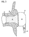
- Fig. 1 is a side elevational view, partially in section, of a stereophonic earphone apparatus generally designated 10 according to the present invention for insertion within an ear canal 12 of a user thereof as shown in Fig. 3.
- the apparatus 10 includes a housing generally designated 14 having a first and a second end 16 and 18 respectively.
- the housing 14 defines an enclosure 20 for the reception therein of an electroacoustic transducer 22.
- a diaphragm 24 is disposed within the enclosure 20 adjacent to the transducer 22.
- the diaphragm 24 defines a peripheral flange 26 which is connected to the housing 14. The arrangement is such that the diaphragm 24 operably cooperates with the transducer 22 for emitting sound waves therefrom.
- a cover 28 is secured to the second end 18 of the housing 14 such that the diaphragm 24 is disposed between the cover 28 and the transducer 22.
- a resilient anchor generally designated 30, has a first and a second extremity 32 and 34 respectively, with the first extremity 32 being removably secured to and extending from the cover 28.
- the anchor 30 is fabricated from a hydrophilic urethane foam 36 having a skinned over outer surface 38. The arrangement is such that when the anchor 30 is compressed as shown in Fig. 2, insertion of the anchor 30 within the ear canal 12 is permitted.
- the foam 36 has a shape restoration memory such that after insertion of the anchor 30 within the ear canal 12, the foam 36 gradually expands as shown in Fig. 3. As the foam 36 expands, the skinned over surface 38 comes into intimate contact with the ear canal 12 to secure the apparatus 10 comfortably within the ear canal 12.
- a tube 46 extends from the cover 28 with the tube 46 being disposed within the passageway 40.
- the tube 46 has an inner and an outer face 48 and 50 respectively so that the outer face 50 of the tube 46 extends contiguously along the passageway 40 so that the tube 46 prevents obturation of the passageway 40 while permitting transmission of sound waves from the diaphragm 24 into the ear canal 12.
- the housing 14 is fabricated from a plastics material.
- plastics material includes polyvinyl chloride (PVC) or any other suitable type of plastic.
- the electroacoustic transducer 22 includes an electrical conductor 52 for connecting the transducer 22 to a sound reproducing device represented generically by the box 54.
- the diaphragm 24, in a preferred embodiment of the present invention, is fabricated from MYLAR®.
- MYLAR® is a Registered Trademark of E. I. Du Pont De Nemours and Company.
- the cover 28 and the tube 46 are fabricated as a one piece molding for directing a transmission therethrough of the sound waves from the diaphragm 24 through the tube 46.
- the skinned over outer surface 38 permits thermal transfer from the ear canal 12 to the foam 36 for further enhancing conformity of the resilient anchor 30 to the ear canal 12 and for inhibiting transmission of extraneous ambient noise past the resilient anchor 30 into the ear canal 12.
- the second termination 44 of the passageway flares outwardly in a direction as indicated by the arrow 56 from the first termination 42 towards the second termination 44 for enhancing a high frequency response of the apparatus 10.
- the tube 46 extends from the first termination 42 of the passageway 40 towards the second termination 44 and more specifically the tube 46 terminates before the second termination 44 of the passageway 40.
- the length 58 and the diameter 60 of the tube 46 are balanced in order to optimize a natural acoustic response of the apparatus 10 and to provide an accurate frequency response thereof.
- the length of the anchor in a preferred embodiment to the present invention is 14 millimeters and the diameter thereof at the first end 32 is 13.7 millimeters.
- the passageway 40 has a diameter of 2.2 millimeters and the flared second end 34 flares outwardly to a diameter of 4.5 millimeters.
- the anchor tapers from the first end 32 to the second end 34 at an angle of 10 degrees.
- the tube 46 has a length of 11.7 millimeters and an internal diameter of 2.2 millimeters with the external diameter of the tube 46 being 3.2 millimeters.
- the foam 36 provides a seal against the ingress into the ear canal 12 of extraneous noise thus providing an extreme base frequency performance.
- the transducer 22 is electrically connected by a cord or electrical cable 52 to audio equipment.
- audio equipment includes a home audio equipment, a portable audio equipment, a computer sound board or any other type of professional sound equipment generically depicted by the box 54.
- an earphone 10 includes a housing 14 having a front face 15, a magnetic circuit or transducer 22 received in the housing 14, a diaphragm 24 magnetically coupled to the magnetic circuit 22, the diaphragm 24 having a diameter D substantially equal to a diameter D1 of the housing 14.
- Resilient member 30 is attached to front face 15 of housing 14 and is aligned with diaphragm 24, for compression insertion into aural meatus or ear canal 12 of a user. Once in the meatus 12, re-expansion occurs so as to provide a high fidelity sonic connection between diaphragm 24 and an eardrum of the user of earphone 10.
- Annular flange 27 extends from front face 15, and flange 27 projects generally normal to the diaphragm 24. Flange 27 fits over and is secured to resilient member 30.
- Resilient member 30 is preferably of frusto-conical configuration and is fabricated from a hydrophilic urethane foam 36. Member 30 has a skinned over outer surface 38 such that when foam 36 expands, the skinned over surface 38 comes into intimate contact with the aural meats 12 to secure the earphone 10 comfortably within the aural meats 12 as best shown in Fig. 3.
- earphone 10 in yet another aspect of the present invention, includes a housing 14, a magnetic circuit or transducer 22 received in the housing 14, a diaphragm 24 magnetically coupled to the magnetic circuit 22.
- the diaphragm 24 has a diameter D substantially equal to a diameter D1 of the housing 14.
- a protector plate cover 28 is attached to the housing 14 for covering the diaphragm 24.
- An annular support flange 27 extends from the protector plate cover 28 and projects generally normal to the cover 28.
- resilient member means 30 has a first and a second extremity 32 and 34 and is arranged to fit the first extremity 32 within the annular flange 27 so that the resilient means 30 connects to cover 28 and projects outwardly therefrom.
- the arrangement is such that when the resilient means 30 is compressed, insertion of the resilient means 30 into an aural meatus 12 of the user is permitted.
- the subsequent re-expansion of the resilient means 30 provides a high fidelity sonic connection between the diaphragm 24 and an eardrum of the user of the earphone 10.
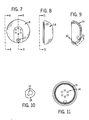
- Fig. 6 is an exploded perspective view of the earphone 10 as shown in Fig. 1 to better illustrate the housing 14, the transducer 22, the cover 28 with the tube 46 extending therefrom, and the resilient member or anchor 30.
- Fig. 8 is a view taken on the line 8-8 of Fig. 7 and shows the housing 14 and an annular ridge 15 for securing the housing 14 to the cover 28.
- Fig. 9 is a sectional view taken on the line 9-9 of Fig. 7 and shows an opening 17 for receiving a resilient strain relief 19 shown in Fig. 4 for relieving the cord 52.
- Fig. 14 is an end view of the cover 28 viewed from the left hand side of Fig. 1 with the anchor removed therefrom.
- Fig. 15 is a sectional view of the cover 28 taken on the line 15-15 of Fig. 14 showing the tube 46 extending from the cover 28.
- Fig. 15A is an enlarged view of a portion of the cover 28 circled in Fig. 15.
- Fig. 15A shows the lip 21 for securing the cover 28 to the housing 14.
- Fig. 17 is a sectional view of a further embodiment of the present invention which includes a tube 46A and a cover 28A which is secured to a housing 14A.
- the housing 14A defines an opening 17A for the reception therein of a resilient cord strain relief 19A so that the cord 52A is guided into the housing 14A.
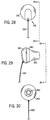
- Fig. 23 is a side elevational view of the earphone shown in Fig. 22 showing the cover 28B disposed between the anchor 30B and the housing 14B.
- Fig. 24 is a view taken on the line 24-24 of Fig. 23 and shows the anchor 30B surrounding the tube 46B.
- Fig. 27 is a perspective view of the earphone shown in Fig. 22 showing the opening 17B and the housing 14B.
- the present invention provides a unique stereophonic earphone apparatus which comfortably fits within the ear canal of a user and which provides an improved frequency response and enhanced base frequency performance.
- the individual components of the apparatus need not be formed in the disclosed shapes, or assembled in the disclosed configuration, but could be provided in virtually any shape, and assembled in virtually any configuration, so that the apparatus may be integrated with other equipment with which it is associated.
Abstract
Description
- The present invention relates in general to the field of stereophonic earphone apparatus. Specifically, a preferred embodiment of the present invention relates to a stereophonic earphone apparatus for insertion within an ear canal of a user thereof.
- As is known to those skilled in the art, various earphone arrangements have been proposed for location adjacent to the opening of the ear canal of the user. Thus, a previously recognized problem has been that such earphones have been less than comfortable. Needless to say, it is desirable to have an earphone that can be worn for an extended period without causing discomfort to the wearer thereof.
- Various means have been proposed for supporting earphones so that such earphones comfortably fit the user's ear. However, such prior art arrangements have been less than successful in achieving such objective.
- Also, with the prior art earphone arrangements, there is a tendency for extraneous noise to leak past the earphone into the ear canal of the user thus reducing the quality of the reproduced sound waves.
- By way of summary, the present invention is directed to a stereophonic earphone apparatus for insertion within an ear canal of a user thereof. The apparatus includes a housing which has a first and a second end. The housing defines an enclosure for the reception therein of an electroacoustic transducer. A diaphragm is disposed within the enclosure adjacent to the transducer with the diaphragm defining a peripheral flange which is connected to the housing such that the diaphragm operably cooperates with the transducer for emitting sound waves therefrom. A cover is secured to the second end of the housing such that the diaphragm is disposed between the cover and the transducer.
- A resilient anchor has a first and second extremity, the first extremity being removably secured to and extending from the cover. The anchor is fabricated from a hydrophilic urethane foam having a skinned over outer surface such that when the anchor is compressed, insertion of the anchor within the ear canal is permitted. The foam has a shape restoration memory such that after insertion of the anchor within the ear canal, the foam gradually expands so that the skinned over surface comes into intimate contact with the ear canal. In this manner, the apparatus is firmly secured within the ear canal.
- The anchor is of a generally conical configuration with the anchor tapering inwardly from the first extremity towards the second extremity. The anchor also defines a longitudinal passageway having a first and a second termination with the first termination being disposed adjacent to the cover and the first extremity of the anchor. A tube extends from the cover and is disposed within the passageway. The tube has an inner and an outer surface the arrangement being such that the outer surface of the tube extends contiguously along the passageway so that the tube prevents obturation of the passageway while permitting transmission of the sound waves from the diaphragm into the ear canal.
- The present invention also includes a method for inserting an earphone within an ear canal of a user thereof, the method comprising the steps of compressing a resilient foam anchor between the user's fingers; subsequently inserting the anchor gently into the ear canal; finally, permitting the foam anchor to gradually expand so that a skinned over outer surface of the foam conforms closely to the shape of the ear canal so that the anchor and a housing attached thereto are comfortably secured relative to the user's ear.
- An effect of the present invention is to enhance the transmission of sound waves from the transducer to the ear canal of the user. A primary object of the invention is to provide an apparatus that is comfortable to wear. Another object of the invention is to provide a unique arrangement which permits the comfortable reception of a resilient anchor within the ear canal of the user thereof so that a high fidelity sonic connection is made between the apparatus and the ear canal of the user.
- A further object of the invention is to provide an earphone apparatus which optimizes a natural acoustic response of the apparatus and provides accurate frequency response thereof.
- These, and other, aspects and objects of the present invention will be better appreciated and understood when considered in conjunction with the following description and the accompanying drawings. It should be understood, however, that the following description, while indicating a preferred embodiment of the present invention, is given by way of illustration and not of limitation. Many changes and modifications may be made within the scope of the present invention without departing from the spirit thereof, and the invention includes all such modifications.
- A clear conception of the advantages and features constituting the present invention, and of the construction and operation of typical mechanisms provided with the present invention, will become more readily apparent by referring to the exemplary, and therefore non-limiting, embodiment illustrated in the drawing accompanying and forming a part of this specification, wherein like reference numerals designate the same elements in the several views, and in which:
- Fig. 1 is a side elevational view, partially in section, of a stereophonic earphone apparatus according to the present invention;
- Fig. 2 is a side elevational view of the apparatus shown in Fig. 1 with the resilient anchor compressed prior to insertion thereof within the ear canal of the user;
- Fig. 3 is a similar view to that shown in Fig. 2, but shows the resilient anchor gradually expanded so that a skinned over surface thereof comes into intimate contact with the ear canal of the user;
- Fig. 4 is a view taken on the line 4-4 of Fig. 1;
- Fig. 5 is a sectional view taken on the line 5-5 of Fig. 1;
- Fig. 6 is an exploded perspective view of the earphone shown in Fig. 1;
- Fig. 7 is a view of the housing viewed from the right hand side of Fig. 1;
- Fig. 8 is a view taken on the line 8-8 of Fig. 7;
- Fig. 9 is a sectional view taken on the line 9-9 of Fig. 7;
- Fig. 10 is a view of a portion of the housing shown in Fig. 1 taken on the line 10-10 of Fig. 9;
- Fig. 11 is a view taken on the line 11-11 of Fig. 8;
- Fig. 12 is a sectional view of the anchor shown in Fig. 1;
- Fig. 13 is a view taken on the line 13-13 of Fig. 12;
- Fig. 14 is a view of the cover shown in Fig. 1 with the anchor removed;
- Fig. 15 is a sectional view taken on the line 15-15 of Fig. 14;
- Fig. 15A is an enlarged view of a portion of the cover shown in Fig. 15;
- Fig. 16 is a view taken on the line 16-16 of Fig. 15;
- Fig. 17 is a sectional view of an alternative embodiment to the present invention with the anchor removed;
- Fig. 18 is a view of the cord relief shown in Fig. 17;
- Fig. 19 is a view taken on the line 19-19 of Fig. 18;
- Fig. 20 is a sectional view taken on the line 20-20 of Fig. 19;
- Fig. 21 is a sectional view taken on the line 21-21 of Fig. 20;
- Fig. 22 is a perspective view of a further embodiment of the present invention;
- Fig. 23 is a side elevational view of the embodiment shown in Fig. 22;
- Fig. 24 is a view taken on the Line 24-24 of Fig. 23;
- Fig. 25 is a sectional view taken on the line 25-25 of Fig. 23;
- Fig. 26 is a view taken on the line 26-26 of Fig. 23;
- Fig. 27 is a perspective view of the embodiment shown in Fig. 22 showing more particularly the housing thereof;
- Fig. 28 is an end view of yet another embodiment of the present invention;
- Fig. 29 is a view taken on the line 29-29 of Fig. 28;
- Fig. 30 is a view taken on the line 30-30 of Fig. 29;
- Fig. 31 is a graph comparing the performance of the present invention with the performance of a prior art earphone; and
- Fig. 32 is a graph comparing the precision noise against frequency of the earphone according to the present invention in comparison with the performance of a prior art earphone.
-
- The present invention and the various features and advantageous details thereof are explained more fully with reference to the non-limiting embodiment described in detail in the following description.
- Referring to the drawings, Fig. 1 is a side elevational view, partially in section, of a stereophonic earphone apparatus generally designated 10 according to the present invention for insertion within an
ear canal 12 of a user thereof as shown in Fig. 3. - The
apparatus 10 includes a housing generally designated 14 having a first and asecond end housing 14 defines anenclosure 20 for the reception therein of anelectroacoustic transducer 22. Adiaphragm 24 is disposed within theenclosure 20 adjacent to thetransducer 22. Thediaphragm 24 defines aperipheral flange 26 which is connected to thehousing 14. The arrangement is such that thediaphragm 24 operably cooperates with thetransducer 22 for emitting sound waves therefrom. Acover 28 is secured to thesecond end 18 of thehousing 14 such that thediaphragm 24 is disposed between thecover 28 and thetransducer 22. - Additionally, a resilient anchor, generally designated 30, has a first and a
second extremity first extremity 32 being removably secured to and extending from thecover 28. Theanchor 30 is fabricated from ahydrophilic urethane foam 36 having a skinned overouter surface 38. The arrangement is such that when theanchor 30 is compressed as shown in Fig. 2, insertion of theanchor 30 within theear canal 12 is permitted. Thefoam 36 has a shape restoration memory such that after insertion of theanchor 30 within theear canal 12, thefoam 36 gradually expands as shown in Fig. 3. As thefoam 36 expands, the skinned oversurface 38 comes into intimate contact with theear canal 12 to secure theapparatus 10 comfortably within theear canal 12. - Referring generally now to Figs. 1-5, more specifically, the
anchor 30 is of truncated conical configuration, theanchor 30 being tapered inwardly from thefirst extremity 32 towards thesecond extremity 34. Also, theanchor 30 defines alongitudinal passageway 40 which has a first andsecond termination first termination 42 is disposed adjacent to thecover 28 and thefirst extremity 32 of theanchor 30. - A
tube 46 extends from thecover 28 with thetube 46 being disposed within thepassageway 40. Thetube 46 has an inner and anouter face outer face 50 of thetube 46 extends contiguously along thepassageway 40 so that thetube 46 prevents obturation of thepassageway 40 while permitting transmission of sound waves from thediaphragm 24 into theear canal 12. - In a more specific embodiment of the present invention, the
housing 14 is fabricated from a plastics material. The term plastics material includes polyvinyl chloride (PVC) or any other suitable type of plastic. Theelectroacoustic transducer 22 includes anelectrical conductor 52 for connecting thetransducer 22 to a sound reproducing device represented generically by thebox 54. - The
diaphragm 24, in a preferred embodiment of the present invention, is fabricated from MYLAR®. MYLAR® is a Registered Trademark of E. I. Du Pont De Nemours and Company. Also, thecover 28 and thetube 46 are fabricated as a one piece molding for directing a transmission therethrough of the sound waves from thediaphragm 24 through thetube 46. - The skinned over
outer surface 38 permits thermal transfer from theear canal 12 to thefoam 36 for further enhancing conformity of theresilient anchor 30 to theear canal 12 and for inhibiting transmission of extraneous ambient noise past theresilient anchor 30 into theear canal 12. - Additionally, the skinned over
outer surface 38 in the vicinity of thesecond extremity 34 of theanchor 30 is curved inwardly so that thesecond extremity 34 is of substantially domed-shaped configuration. - The
second termination 44 of the passageway flares outwardly in a direction as indicated by thearrow 56 from thefirst termination 42 towards thesecond termination 44 for enhancing a high frequency response of theapparatus 10. - Also, the
tube 46 extends from thefirst termination 42 of thepassageway 40 towards thesecond termination 44 and more specifically thetube 46 terminates before thesecond termination 44 of thepassageway 40. - The
length 58 and thediameter 60 of thetube 46 are balanced in order to optimize a natural acoustic response of theapparatus 10 and to provide an accurate frequency response thereof. - More specifically, the length of the anchor in a preferred embodiment to the present invention is 14 millimeters and the diameter thereof at the
first end 32 is 13.7 millimeters. Thepassageway 40 has a diameter of 2.2 millimeters and the flaredsecond end 34 flares outwardly to a diameter of 4.5 millimeters. The anchor tapers from thefirst end 32 to thesecond end 34 at an angle of 10 degrees. - The
tube 46 has a length of 11.7 millimeters and an internal diameter of 2.2 millimeters with the external diameter of thetube 46 being 3.2 millimeters. - Additionally, the
foam 36 provides a seal against the ingress into theear canal 12 of extraneous noise thus providing an extreme base frequency performance. - Furthermore, the
transducer 22 is electrically connected by a cord orelectrical cable 52 to audio equipment. Such audio equipment includes a home audio equipment, a portable audio equipment, a computer sound board or any other type of professional sound equipment generically depicted by thebox 54. - In a further aspect of the present invention, an
earphone 10 includes ahousing 14 having afront face 15, a magnetic circuit ortransducer 22 received in thehousing 14, adiaphragm 24 magnetically coupled to themagnetic circuit 22, thediaphragm 24 having a diameter D substantially equal to a diameter D1 of thehousing 14. -
Resilient member 30 is attached tofront face 15 ofhousing 14 and is aligned withdiaphragm 24, for compression insertion into aural meatus orear canal 12 of a user. Once in themeatus 12, re-expansion occurs so as to provide a high fidelity sonic connection betweendiaphragm 24 and an eardrum of the user ofearphone 10. -
Annular flange 27 extends fromfront face 15, andflange 27 projects generally normal to thediaphragm 24.Flange 27 fits over and is secured toresilient member 30.Resilient member 30 is preferably of frusto-conical configuration and is fabricated from ahydrophilic urethane foam 36.Member 30 has a skinned overouter surface 38 such that whenfoam 36 expands, the skinned oversurface 38 comes into intimate contact with theaural meats 12 to secure theearphone 10 comfortably within theaural meats 12 as best shown in Fig. 3. - In yet another aspect of the present invention,
earphone 10 includes ahousing 14, a magnetic circuit ortransducer 22 received in thehousing 14, adiaphragm 24 magnetically coupled to themagnetic circuit 22. Thediaphragm 24 has a diameter D substantially equal to a diameter D1 of thehousing 14. Aprotector plate cover 28 is attached to thehousing 14 for covering thediaphragm 24. Anannular support flange 27 extends from theprotector plate cover 28 and projects generally normal to thecover 28. - Also, resilient member means 30 has a first and a
second extremity first extremity 32 within theannular flange 27 so that the resilient means 30 connects to cover 28 and projects outwardly therefrom. The arrangement is such that when the resilient means 30 is compressed, insertion of the resilient means 30 into anaural meatus 12 of the user is permitted. The subsequent re-expansion of the resilient means 30 provides a high fidelity sonic connection between thediaphragm 24 and an eardrum of the user of theearphone 10. - Fig. 6 is an exploded perspective view of the
earphone 10 as shown in Fig. 1 to better illustrate thehousing 14, thetransducer 22, thecover 28 with thetube 46 extending therefrom, and the resilient member oranchor 30. - Fig. 7 is a view similar to that shown in Fig. 4 with the
cord 52 removed from thehousing 14. - Fig. 8 is a view taken on the line 8-8 of Fig. 7 and shows the
housing 14 and anannular ridge 15 for securing thehousing 14 to thecover 28. - Fig. 9 is a sectional view taken on the line 9-9 of Fig. 7 and shows an
opening 17 for receiving aresilient strain relief 19 shown in Fig. 4 for relieving thecord 52. - Fig. 10 is a view taken on the line 10-10 of Fig. 9 and shows the
opening 17 for receiving therelief 19. - Fig. 11 is a view taken on the line 11-11 of Fig. 8 and shows the
annular ridge 15 for fastening thehousing 14 to thecover 28. - Fig. 12 is a sectional view of the
anchor 30 shown in Fig. 1 shows the skinned oversurface 38 thereof. - Fig. 13 is a view taken on the line 13-13 of Fig. 12 and shows the skinned over
surface 38 extending around the circumference of theanchor 30. - Fig. 14 is an end view of the
cover 28 viewed from the left hand side of Fig. 1 with the anchor removed therefrom. - Fig. 15 is a sectional view of the
cover 28 taken on the line 15-15 of Fig. 14 showing thetube 46 extending from thecover 28. - Fig. 16 is a view taken on the line 16-16 of Fig. 15 and shows a
lip 21 which cooperates with theridge 15 of thehousing 14 for securing thecover 28 relative to thehousing 14. - Fig. 15A is an enlarged view of a portion of the
cover 28 circled in Fig. 15. Fig. 15A shows thelip 21 for securing thecover 28 to thehousing 14. - Fig. 17 is a sectional view of a further embodiment of the present invention which includes a
tube 46A and acover 28A which is secured to ahousing 14A. Thehousing 14A defines anopening 17A for the reception therein of a resilientcord strain relief 19A so that thecord 52A is guided into thehousing 14A. - Fig. 18 is a side elevational view of the
cord strain relief 19A. The rounded shape of thestrain relief 19A allows the relief to avoid contact with the user's ear, thus enhancing wearing comfort. - Fig. 19 is a view taken on the line 19-19 of Fig. 18 and shows the
cord relief 19A having cut awayportions 23A for permitting flexing of thecord 52A relative to thehousing 14A. - Fig. 20 is a sectional view taken on the line 20-20 of Fig. 19 and shows the
cord 52A guided by thecord relief 19A. - Fig. 21 is a sectional view taken on the line 21-21 of Fig. 20 and shows the
opening 17A for the reception therein of thecord relief 19A. - Fig. 22 is a perspective view of a further embodiment of the present invention showing a
resilient anchor 30B and ahousing 14B. - Fig. 23 is a side elevational view of the earphone shown in Fig. 22 showing the
cover 28B disposed between theanchor 30B and thehousing 14B. - Fig. 24 is a view taken on the line 24-24 of Fig. 23 and shows the
anchor 30B surrounding thetube 46B. - Fig. 25 is a sectional view taken on the line 25-25 of Fig. 23 and shows the
tube 46B extending through thepassageway 40B of theanchor 30B. Additionally, thetube 46B includes an integral outwardly extendingannular collar 25B which freely permits insertion of thetube 46B within thepassageway 40B of theanchor 30B. However, thecollar 25B tends to inhibit axial movement as indicated by thearrow 27B of theanchor 30B relative to thetube 46B. The provision of thecollar 25B prevents theanchor 30B from sliding off thetube 46B when the earphone is removed from the ear canal. However, thecollar 25B permits removal of theanchor 30B for replacement thereof for hygienic reasons. - Fig. 26 is a view taken on the line 26-26 of Fig. 23 and shows the
housing 14B and theopening 17B for the reception therein of the cord relief not shown. - Fig. 27 is a perspective view of the earphone shown in Fig. 22 showing the
opening 17B and thehousing 14B. - Fig. 28 is an end view of yet another embodiment of the present invention which shows a
housing 14C with acord 52C extending therefrom. - Fig. 29 is a view taken on the line 29-29 of Fig. 28 and shows the
housing 14C and theanchor 30C with acover 28C disposed therebetween. - Fig. 30 is a view taken on the line 30-30 of Fig. 29 and shows the
tube 46C surrounded by theanchor 30C. - Fig. 31 is a graph which compares the performance of the
earphone 10 according to the present invention with the performance of prior art earphones. In Fig. 31, the performance of the earphone according to the present invention is shown by theline 62 while the performance of one known prior art arrangement is depicted by a graph having aline 64. The performance of a second is shown byline 66. - The graph of Fig. 31 shows a plot of amplitude vs. frequency response for the stereophonic earphone apparatus of the present invention. The earphone of the present invention (62) is compared in this plot to other stereophones in the an (64, 66). The prior an stereophones' response illustrated in the plot is indicative of the prior art amplitude vs. frequency response in prior art earbud-type stereophones. The direct comparison of the present invention data with representative prior art data demonstrates that present invention provides superior low frequency performance. This low frequency performance is a direct result of the novel features including the improved seal between the ear canal and the resilient member or anchor of the invention. Those skilled in the art will also readily appreciate from the aforementioned graphs that the high frequency response and the extended bass performance is enhanced by the provisions of the present invention.
- Figure 32 is a graph comparing the audio noise amplitude vs. frequency for the stereophonic earphone apparatus according to the present invention with another prior art device. The present invention's noise reduction performance is compared to the noise reduction performance of a prior art foam hearing protector ear plug.
- In Figure 32's frequency vs. amplitude plot of the acoustic noise isolation, the enhanced capability of the invention is illustrated. During testing, the invention is inserted in an artificial ear coupler with microphone and wide band noise is then generated in the area around the subject apparatus and coupler. The plot of Figure 32 in part shows the amount of noise isolation that can be expected from the present invention. Preferably, the present invention is perfectly inserted into an ear canal. The dashed
line 68 shows a comparison plot of a typical commercial foam ear plug hearing protector. Base line of noise is also shown. - In operation of the apparatus according to the present invention, the user compresses the
resilient anchor 30 between the user's fingers and then inserts the anchor gently into theear canal 12 as best shown in Fig. 2. Subsequently, thefoam 36 gradually expands so that the skinned overouter surface 38 of the foam conforms closely to the shape of theear canal 12 so that the anchor and thehousing 14 attached thereto are comfortably secured relative to the user's ear as best shown in Fig. 3. - Additionally, heat from the user's ear flows through the skinned over
surface 38 to thefoam 36 thus tending to further soften the foam in the vicinity of the lining of the ear canal. Thus, theanchor 30 becomes even more comfortably secured within the ear canal. Further, outside extraneous noises are sealed off from the ear canal by virtue of the close conformity of the skinned oversurface 38 with theear canal 12. - The present invention provides a unique stereophonic earphone apparatus which comfortably fits within the ear canal of a user and which provides an improved frequency response and enhanced base frequency performance.
- Moreover, the individual components of the apparatus need not be formed in the disclosed shapes, or assembled in the disclosed configuration, but could be provided in virtually any shape, and assembled in virtually any configuration, so that the apparatus may be integrated with other equipment with which it is associated.
- It is intended that the appended claims cover all such additions, modifications and rearrangements. Expedient embodiments of the present invention are differentiated by the appended subclaims.
Claims (20)
- A stereophonic earphone apparatus for insertion within an ear canal of a user thereof, said apparatus comprising:a housing having a first and a second end, said housing defining an enclosure;an electroacoustic transducer disposed within said enclosure;a diaphragm disposed within said enclosure adjacent to said transducer, said diaphragm defining a peripheral flange which is connected to said housing such that said diaphragm operably cooperates with said transducer for emitting sound waves therefrom;a cover secured to said second end of said housing such that said diaphragm is disposed between said cover and said transducer;a resilient anchor having a first and a second extremity, said first extremity being removably secured to and extending from said cover, said anchor being fabricated from a hydrophilic urethane foam having a skinned over outer surface such that, when said anchor is compressed, insertion of said anchor within the ear canal is permitted, said foam having a shape restoration memory such that after insertion of said anchor within the ear canal, said foam gradually expands so that said skinned over surface comes into intimate contact with the ear canal to comfortably secure said apparatus within the ear canal;said anchor being of generally conical configuration, said anchor tapering inwardly from said first extremity towards said second extremity, said anchor defining a longitudinal passageway having a first and a second termination, said first termination being disposed adjacent to said cover and said first extremity of said anchor; anda tube extending from said cover, said tube being disposed within said passageway, said tube having an inner and an outer face, the arrangement being such that said outer face of said tube extends contiguously along said passageway so that said tube prevents obturation of said passageway, while permitting transmission of said sound waves from said diaphragm into the ear canal.
- An earphone apparatus as set forth in claim 1 wherein said housing is fabricated from a plastics material.
- An earphone apparatus as set forth in claim 1 wherein said electroacoustic transducer includes:an electrical conductor for connecting said transducer to a sound reproducing device.
- An earphone apparatus as set forth in claim 1 wherein said diaphragm is fabricated from MYLAR®.
- An earphone apparatus as set forth in claim 1 wherein said cover and said tube are fabricated as a one piece molding for directing transmission therethrough of said sound waves from said diaphragm through said tube.
- An earphone apparatus as set forth in claim 1 wherein said skinned over surface permits thermal transfer from the ear canal to said foam for further enhancing conformity of said resilient anchor to the ear canal and for inhibiting transmission of extraneous ambient noise past said resilient anchor to said ear canal.
- An earphone apparatus as set forth in claim 1 wherein said skinned over surface in the vicinity of said second extremity of said anchor, is curved inwardly so that said second extremity is of substantially dome-shaped configuration.
- An earphone apparatus as set forth in claim 1 wherein said second termination of said passageway flares outwardly in a direction from said first termination towards said second termination for enhancing a high frequency response of said apparatus.
- An earphone apparatus as set forth in claim 1 wherein said tube extends from said first termination of said passageway towards said second termination.
- An earphone apparatus as set forth in claim 1 wherein said tube extends from said first termination of said passageway towards said second termination, said tube terminating before said second termination of said passageway.
- An earphone apparatus as set forth in claim 1 wherein a length and diameter of said tube are balanced in order to optimize a natural acoustic response of said apparatus and to provide accurate frequency response thereof.
- An earphone apparatus as set forth in claim 1 wherein said foam provides a seal against ingress of extraneous noise into the ear canal thus providing an extreme extended bass frequency performance.
- An earphone apparatus as set forth in claim 1 wherein said transducer is selectively electrically connected to audio equipment.
- An earphone comprising:a housing having a front face;a magnetic circuit received in said housing;a diaphragm magnetically coupled to said magnetic circuit, said diaphragm having a diameter substantially equal to a diameter of said housing;a resilient support member attached to said front face of said housing and aligned with said diaphragm, for compression insertion into an aural meatus of a user and re-expansion so as to provide a high fidelity sonic connection between said diaphragm and an eardrum of a user of the earphone; andan annular flange extending from said front face, said flange projecting generally normal to said diaphragm, said flange fitting over and being secured to said resilient member;said resilient support member being of frusto-conical configuration, said resilient member being fabricated from a hydrophilic urethane foam having a skinned over outer surface such that when said foam expands, said skinned over surface comes into intimate contact with the aural meatus to comfortably secure the earphone within the aural meatus.
- An earphone as set forth in claim 14 further including a protector plate cover attached to said housing for covering said diaphragm such that said resilient support member is connected to said protector plate cover.
- An earphone comprising:a housing;a magnetic circuit received in said housing;a diaphragm magnetically coupled to said magnetic circuit, said diaphragm having a diameter substantially equal to a diameter of said housing;a protector plate cover attached to said housing for covering said diaphragm;an annular support flange extending from said protector plate cover and projecting generally normal to said cover, andresilient support means having a first and a second extremity, said first extremity fitting within said annular flange so that said resilient support means is connected to said cover and projects outwardly therefrom, the arrangement being such that when said resilient support means is compressed, insertion of said resilient support means into an aural meatus of the user is permitted and subsequent reexpansion of said resilient support means provides a high fidelity sonic connection between said diaphragm and an eardrum of the user of the earphone.
- An earphone as set forth in claim 16 wherein said resilient support means is of frusto conical configuration.
- A method for inserting an earphone within an ear canal of a user thereof, said method comprising the steps of:compressing a resilient foam anchor between the user's fingers;subsequently inserting the anchor gently into the ear canal; andpermitting the foam anchor to gradually expand so that a skinned outer surface of the foam conforms closely to the shape of the ear canal so that the anchor and a housing attached thereto are comfortably secured relative to the user's ear.
- A method for inserting an earphone within an ear canal of a user thereof as set forth in claim 18 further including the step of:allowing heat from the user's ear to flow through the skinned over surface to the foam thus tending to further soften the foam in the vicinity of the lining of the ear canal so that the anchor becomes even more comfortably secured within the ear canal and so that outside extraneous noises are sealed off from the ear canal by virtue of the close conformity of the skinned over surface with the ear canal.
- The earphone of claim 1 further comprising a collar integral with the tube to inhibit movement of the anchor.
Applications Claiming Priority (2)
| Application Number | Priority Date | Filing Date | Title |
|---|---|---|---|
| US257664 | 1988-10-14 | ||
| US25766499A | 1999-02-25 | 1999-02-25 |
Publications (2)
| Publication Number | Publication Date |
|---|---|
| EP1032243A2 true EP1032243A2 (en) | 2000-08-30 |
| EP1032243A3 EP1032243A3 (en) | 2007-03-14 |
Family
ID=22977228
Family Applications (1)
| Application Number | Title | Priority Date | Filing Date |
|---|---|---|---|
| EP00101714A Withdrawn EP1032243A3 (en) | 1999-02-25 | 2000-01-27 | A stereophonic earphone apparatus |
Country Status (7)
| Country | Link |
|---|---|
| EP (1) | EP1032243A3 (en) |
| JP (1) | JP2000253478A (en) |
| KR (1) | KR20000058143A (en) |
| AU (1) | AU1637000A (en) |
| BR (1) | BR0000773A (en) |
| CA (1) | CA2297423A1 (en) |
| TW (1) | TW478286B (en) |
Cited By (13)
| Publication number | Priority date | Publication date | Assignee | Title |
|---|---|---|---|---|
| WO2007079948A1 (en) * | 2005-12-29 | 2007-07-19 | Sennheiser Electronic Gmbh & Co.Kg | Headphones |
| GB2438910A (en) * | 2006-06-09 | 2007-12-12 | Cotron Corp | Earphone with a sound guiding tube |
| CN1992989B (en) * | 2005-12-29 | 2011-08-03 | 三星电子株式会社 | Earphone having variable duct unit |
| WO2013119913A1 (en) * | 2012-02-08 | 2013-08-15 | Decibullz Llc | Moldable earpiece system |
| CN103826188A (en) * | 2014-02-21 | 2014-05-28 | 青岛歌尔声学科技有限公司 | In-ear type moving iron earphones and headset with same |
| US9179211B2 (en) | 2012-02-08 | 2015-11-03 | Decibullz Llc | Double seal moldable earpiece system |
| US10149038B2 (en) | 2017-01-20 | 2018-12-04 | Decibullz Llc | Earpiece intra-auricular support system |
| USD836614S1 (en) | 2013-02-07 | 2018-12-25 | Decibullz Llc | Moldable earpiece |
| US10321219B2 (en) | 2015-12-28 | 2019-06-11 | Hearing Components, Inc. | Earphone tip with universal sound port attachment core |
| US10507599B2 (en) | 2017-04-07 | 2019-12-17 | Decibullz Llc | Moldable earpiece heating case |
| US10728648B2 (en) | 2017-08-23 | 2020-07-28 | Decibullz Llc | Reconfigurable intra-auricular support |
| USD925493S1 (en) | 2019-11-25 | 2021-07-20 | Decibullz Llc | Intra-auricular earbud support |
| WO2022016511A1 (en) * | 2020-07-24 | 2022-01-27 | 华为技术有限公司 | Active noise cancellation method and apparatus |
Families Citing this family (3)
| Publication number | Priority date | Publication date | Assignee | Title |
|---|---|---|---|---|
| WO2009133873A1 (en) | 2008-04-30 | 2009-11-05 | Sato Kenji | Acoustic device |
| CN101370320B (en) * | 2008-09-27 | 2012-05-30 | 刘国清 | Earplug made of wood and metal or made of plastic, wood and metal and production method thereof |
| CN103269466B (en) * | 2013-05-24 | 2017-02-08 | 青岛歌尔声学科技有限公司 | Earplug matched with ear in shape |
Citations (6)
| Publication number | Priority date | Publication date | Assignee | Title |
|---|---|---|---|---|
| US2430229A (en) * | 1943-10-23 | 1947-11-04 | Zenith Radio Corp | Hearing aid earpiece |
| GB606272A (en) * | 1945-08-23 | 1948-08-11 | Zenith Radio Corp | Improvements in earphone assemblies |
| EP0383483A1 (en) * | 1989-02-13 | 1990-08-22 | Koss Corporation | Earphone having resilient insertion device |
| US5002151A (en) * | 1986-12-05 | 1991-03-26 | Minnesota Mining And Manufacturing Company | Ear piece having disposable, compressible polymeric foam sleeve |
| US5319163A (en) * | 1990-06-07 | 1994-06-07 | Scott Robert T | Waterproof earmold-to-earphone adapter |
| WO1999007182A2 (en) * | 1997-07-29 | 1999-02-11 | Decibel Instruments, Inc. | Acoustic coupler |
-
2000
- 2000-01-27 EP EP00101714A patent/EP1032243A3/en not_active Withdrawn
- 2000-01-28 CA CA002297423A patent/CA2297423A1/en not_active Abandoned
- 2000-02-11 AU AU16370/00A patent/AU1637000A/en not_active Abandoned
- 2000-02-18 JP JP2000041300A patent/JP2000253478A/en active Pending
- 2000-02-22 KR KR1020000008544A patent/KR20000058143A/en not_active Application Discontinuation
- 2000-02-23 BR BR0000773-0A patent/BR0000773A/en not_active Application Discontinuation
- 2000-05-29 TW TW089103259A patent/TW478286B/en not_active IP Right Cessation
Patent Citations (6)
| Publication number | Priority date | Publication date | Assignee | Title |
|---|---|---|---|---|
| US2430229A (en) * | 1943-10-23 | 1947-11-04 | Zenith Radio Corp | Hearing aid earpiece |
| GB606272A (en) * | 1945-08-23 | 1948-08-11 | Zenith Radio Corp | Improvements in earphone assemblies |
| US5002151A (en) * | 1986-12-05 | 1991-03-26 | Minnesota Mining And Manufacturing Company | Ear piece having disposable, compressible polymeric foam sleeve |
| EP0383483A1 (en) * | 1989-02-13 | 1990-08-22 | Koss Corporation | Earphone having resilient insertion device |
| US5319163A (en) * | 1990-06-07 | 1994-06-07 | Scott Robert T | Waterproof earmold-to-earphone adapter |
| WO1999007182A2 (en) * | 1997-07-29 | 1999-02-11 | Decibel Instruments, Inc. | Acoustic coupler |
Cited By (28)
| Publication number | Priority date | Publication date | Assignee | Title |
|---|---|---|---|---|
| WO2007079948A1 (en) * | 2005-12-29 | 2007-07-19 | Sennheiser Electronic Gmbh & Co.Kg | Headphones |
| CN1992989B (en) * | 2005-12-29 | 2011-08-03 | 三星电子株式会社 | Earphone having variable duct unit |
| GB2438910A (en) * | 2006-06-09 | 2007-12-12 | Cotron Corp | Earphone with a sound guiding tube |
| US7697710B2 (en) | 2006-06-09 | 2010-04-13 | Cotron Corporation | Earphone with a sound guiding tube |
| GB2438910B (en) * | 2006-06-09 | 2011-06-22 | Cotron Corp | Earphone with a sound guiding tube |
| US9451353B2 (en) | 2012-02-08 | 2016-09-20 | Decibullz Llc | Moldable earpiece system |
| US9179211B2 (en) | 2012-02-08 | 2015-11-03 | Decibullz Llc | Double seal moldable earpiece system |
| US10779073B2 (en) | 2012-02-08 | 2020-09-15 | Decibullz Llc | Moldable earpiece system |
| US9628889B2 (en) | 2012-02-08 | 2017-04-18 | Decibullz Llc | Moldable earpiece system |
| US9769555B2 (en) | 2012-02-08 | 2017-09-19 | Decibullz Llc | Moldable earpiece system |
| US10091571B2 (en) | 2012-02-08 | 2018-10-02 | Decibullz Llc | Moldable earpiece system |
| US11750961B2 (en) | 2012-02-08 | 2023-09-05 | Decibullz Llc | Moldable earpiece system |
| WO2013119913A1 (en) * | 2012-02-08 | 2013-08-15 | Decibullz Llc | Moldable earpiece system |
| US11303986B2 (en) | 2012-02-08 | 2022-04-12 | Decibullz Llc | Moldable earpiece system |
| USD836614S1 (en) | 2013-02-07 | 2018-12-25 | Decibullz Llc | Moldable earpiece |
| USD865721S1 (en) | 2013-02-07 | 2019-11-05 | Decibullz Llc | Moldable earpiece |
| CN103826188A (en) * | 2014-02-21 | 2014-05-28 | 青岛歌尔声学科技有限公司 | In-ear type moving iron earphones and headset with same |
| US10321219B2 (en) | 2015-12-28 | 2019-06-11 | Hearing Components, Inc. | Earphone tip with universal sound port attachment core |
| US10856065B2 (en) | 2017-01-20 | 2020-12-01 | Decibullz Llc | Earpiece intra-auricular support system |
| US10462552B2 (en) | 2017-01-20 | 2019-10-29 | Decibullz Llc | Earpiece intra-auricular support system |
| US11381902B2 (en) | 2017-01-20 | 2022-07-05 | Decibullz Llc | Earpiece intra-auricular support system |
| US11606639B2 (en) | 2017-01-20 | 2023-03-14 | Decibullz Llc | Earpiece intra-auricular support system |
| US10149038B2 (en) | 2017-01-20 | 2018-12-04 | Decibullz Llc | Earpiece intra-auricular support system |
| US10507599B2 (en) | 2017-04-07 | 2019-12-17 | Decibullz Llc | Moldable earpiece heating case |
| US10728648B2 (en) | 2017-08-23 | 2020-07-28 | Decibullz Llc | Reconfigurable intra-auricular support |
| US11490189B2 (en) | 2017-08-23 | 2022-11-01 | Decibullz Llc | Reconfigurable intra-auricular support |
| USD925493S1 (en) | 2019-11-25 | 2021-07-20 | Decibullz Llc | Intra-auricular earbud support |
| WO2022016511A1 (en) * | 2020-07-24 | 2022-01-27 | 华为技术有限公司 | Active noise cancellation method and apparatus |
Also Published As
| Publication number | Publication date |
|---|---|
| KR20000058143A (en) | 2000-09-25 |
| BR0000773A (en) | 2000-10-24 |
| EP1032243A3 (en) | 2007-03-14 |
| AU1637000A (en) | 2000-08-31 |
| CA2297423A1 (en) | 2000-08-25 |
| TW478286B (en) | 2002-03-01 |
| JP2000253478A (en) | 2000-09-14 |
Similar Documents
| Publication | Publication Date | Title |
|---|---|---|
| US10200778B2 (en) | Earpiece with ergonomic extension | |
| EP1032243A2 (en) | A stereophonic earphone apparatus | |
| US4972492A (en) | Earphone | |
| US7424123B2 (en) | Canal hearing device with tubular insert | |
| US6359993B2 (en) | Conformal tip for a hearing aid with integrated vent and retrieval cord | |
| US6382346B2 (en) | Retention and extraction device for a hearing aid | |
| US5979589A (en) | Flexible hearing aid | |
| US7899200B2 (en) | Universal-fit hearing device | |
| US5917918A (en) | In-ear-canal audio receiver and stethoscope having the same | |
| US10791390B2 (en) | Flex-fit ear tip for headphones | |
| US20100166241A1 (en) | Hearing aid ear dome | |
| JP7079274B2 (en) | Flexible earpieces for hearing aids | |
| US11381897B2 (en) | Variable eartip for earphone | |
| EP3334179B1 (en) | Hearing aid with an extended dome | |
| US20220232308A1 (en) | Modular Earphone | |
| CN114125678A (en) | Dome for hearing aid | |
| EP0383483A1 (en) | Earphone having resilient insertion device | |
| CN211128133U (en) | In-ear earphone | |
| MXPA00001858A (en) | A stereophonic earphone apparatus | |
| EP4164252A2 (en) | Earpiece and hearing aid device comprising it | |
| KR20030062146A (en) | Headset |
Legal Events
| Date | Code | Title | Description |
|---|---|---|---|
| PUAI | Public reference made under article 153(3) epc to a published international application that has entered the european phase |
Free format text: ORIGINAL CODE: 0009012 |
|
| AK | Designated contracting states |
Kind code of ref document: A2 Designated state(s): AT BE CH CY DE DK ES FI FR GB GR IE IT LI LU MC NL PT SE |
|
| AX | Request for extension of the european patent |
Free format text: AL;LT;LV;MK;RO;SI |
|
| PUAL | Search report despatched |
Free format text: ORIGINAL CODE: 0009013 |
|
| AK | Designated contracting states |
Kind code of ref document: A3 Designated state(s): AT BE CH CY DE DK ES FI FR GB GR IE IT LI LU MC NL PT SE |
|
| AX | Request for extension of the european patent |
Extension state: AL LT LV MK RO SI |
|
| 17P | Request for examination filed |
Effective date: 20070814 |
|
| 17Q | First examination report despatched |
Effective date: 20071008 |
|
| AKX | Designation fees paid |
Designated state(s): AT BE CH CY DE DK ES FI FR GB GR IE IT LI LU MC NL PT SE |
|
| STAA | Information on the status of an ep patent application or granted ep patent |
Free format text: STATUS: THE APPLICATION IS DEEMED TO BE WITHDRAWN |
|
| 18D | Application deemed to be withdrawn |
Effective date: 20080219 |