EP1032983B1 - Method and apparatus for receiving radio signals - Google Patents
Method and apparatus for receiving radio signals Download PDFInfo
- Publication number
- EP1032983B1 EP1032983B1 EP98954881A EP98954881A EP1032983B1 EP 1032983 B1 EP1032983 B1 EP 1032983B1 EP 98954881 A EP98954881 A EP 98954881A EP 98954881 A EP98954881 A EP 98954881A EP 1032983 B1 EP1032983 B1 EP 1032983B1
- Authority
- EP
- European Patent Office
- Prior art keywords
- antenna
- signals
- beams
- receiver system
- assemblies
- Prior art date
- Legal status (The legal status is an assumption and is not a legal conclusion. Google has not performed a legal analysis and makes no representation as to the accuracy of the status listed.)
- Expired - Lifetime
Links
Images


Classifications
-
- H—ELECTRICITY
- H04—ELECTRIC COMMUNICATION TECHNIQUE
- H04B—TRANSMISSION
- H04B7/00—Radio transmission systems, i.e. using radiation field
- H04B7/02—Diversity systems; Multi-antenna system, i.e. transmission or reception using multiple antennas
-
- H—ELECTRICITY
- H04—ELECTRIC COMMUNICATION TECHNIQUE
- H04B—TRANSMISSION
- H04B7/00—Radio transmission systems, i.e. using radiation field
- H04B7/02—Diversity systems; Multi-antenna system, i.e. transmission or reception using multiple antennas
- H04B7/04—Diversity systems; Multi-antenna system, i.e. transmission or reception using multiple antennas using two or more spaced independent antennas
- H04B7/08—Diversity systems; Multi-antenna system, i.e. transmission or reception using multiple antennas using two or more spaced independent antennas at the receiving station
- H04B7/0837—Diversity systems; Multi-antenna system, i.e. transmission or reception using multiple antennas using two or more spaced independent antennas at the receiving station using pre-detection combining
- H04B7/0842—Weighted combining
- H04B7/086—Weighted combining using weights depending on external parameters, e.g. direction of arrival [DOA], predetermined weights or beamforming
-
- H—ELECTRICITY
- H04—ELECTRIC COMMUNICATION TECHNIQUE
- H04B—TRANSMISSION
- H04B7/00—Radio transmission systems, i.e. using radiation field
- H04B7/02—Diversity systems; Multi-antenna system, i.e. transmission or reception using multiple antennas
- H04B7/10—Polarisation diversity; Directional diversity
-
- H—ELECTRICITY
- H04—ELECTRIC COMMUNICATION TECHNIQUE
- H04B—TRANSMISSION
- H04B7/00—Radio transmission systems, i.e. using radiation field
- H04B7/02—Diversity systems; Multi-antenna system, i.e. transmission or reception using multiple antennas
- H04B7/04—Diversity systems; Multi-antenna system, i.e. transmission or reception using multiple antennas using two or more spaced independent antennas
- H04B7/08—Diversity systems; Multi-antenna system, i.e. transmission or reception using multiple antennas using two or more spaced independent antennas at the receiving station
- H04B7/0891—Space-time diversity
- H04B7/0894—Space-time diversity using different delays between antennas
Definitions
- the present invention relates to radio systems and, more particularly, to a method and apparatus for receiving radio signals with the aid of antenna beams.
- the quality of a received radio signal is affected by many natural phenomena.
- time dispersion is caused by a signal on its way from a transmitter being reflected by obstacles at different locations in the propagation path before reaching the receiver.
- the signal will arrive at the receiver at different time delays, due to the different propagation paths along which the signal travel.
- time dispersed signals can be successfully restored. It is well known to a person skilled in this art to use a RAKE-receiver or an equalizer to restore a time dispersed signal.
- One well known method of combatting fading is to provide the radio receiving station with an antenna diversity system.
- the system comprises two or more receiving antennas separated either spatially or by orthogonal polarization directions, or by a combination thereof.
- fading of the signals received by each antenna are less correlated, thus decreasing the possibility of both antennas being exposed to a fading dip at one and the same time.
- the radio receiver station is provided with separate receiver branches for each receiving antenna.
- a third phenomenon troublesome to radio transmission is that of interference.
- An interfering signal can be characterized as any undesired signal received on the same channel as the desired signal.
- jamming i.e. intentional disturbance by the enemy.
- cellular radio systems the interference problem is closely related to the capacity demand for communication.
- the radio spectrum is a scarce resource, a radio frequency band given to a cellular operator must be used efficiently. For this reason the operators service area is divided into cells and radio channels used in one cell are reused in cells that have a minimum number of cells in-between. Because of the popularity of mobile phones, the demand for traffic capacity has grown rapidly.
- One way of handling the capacity demand is to decrease the size of the cells, thus enabling closer reuse of the channels per area unit and thereby raising the communication capacity of a given area while still preserving the frequency-reuse-factor.
- Radio base station In areas where the capacity demand is high, such as in city centres and railway stations, it is often difficult to find sites for base stations.
- An available place for a base station may have the form of a wall on which it can be hung.
- it is important that the radio base station is small and demands less power.
- the size of the radio base station is related to the power consumption, since power necessitates cooling and cooling necessitates space.
- the appearance of the installation is also important, for instance with respect to obtaining permission from the authorities to use a new radio base station site.
- An adaptive antenna is commonly comprised of an antenna array connected to beam forming means.
- the adaptive antenna forms a set of antenna beams which each covers a narrow predefined space area and which together cover a wide predefined area omnidirectionally or within a sector.
- a signal sent from a mobile transmitter is received by each of the antenna beams, each version of the signal being separately received and thereby the angular information being maintained.
- the angular information is inherent in the phase difference between the different versions of the signal.
- An estimation of the direction to the signal source is made on the basis of the demodulated versions of the received signal. This estimated parameter is also called DOA, direction of arrival.
- signals received by each beam must be received separatly by corresponding radio receiver branches.
- the DOA-estimation is used for the selection of one or more antenna beams, or for directing of a narrow steerable beam, for transmission in the downlink to the mobile of interest. Transmission in the chosen beam is directed to the mobile station whereby mobiles that use the same channel in other directions will be less exposed to interference. Downlink interference is thus combated by means of the adaptive antenna technique.
- WO 9623329 relates to the problem of how to achieve high antenna gain for mobiles at great distance and at the same time limit the problems of beam crossovers in a antenna arrangement with several narrow beams.
- the later problem occurs when the mobile station moves out of the direction of one beam and into the direction of a next beam.
- the solution is solved by providing two separate sets of antenna beams. The beams in the two sets are partly overlapping each other, a beam if one of the sets partly overlap two beams of the other set and the peak direction of the first set beam is in the intersection between the two beams of the other set of beams.
- US patent specification, US 5563610 addresses the use of a multi-beamforming antenna for the purpose of gaining antenna diversity based on the different beams being very narrow and covering disjunct areas. This is called angular diversity and results in the signals received in separate beams being uncorrelated.
- US 5563610 teaches a receiving system in which branches from each antenna beam are distributed into two groups. In one group signals are delayed in relation to one another and then combined. Two combined signals, each derived from a corresponding of the two groups, are thus obtained and then fed to a conventional CDMA-receiver.
- the present invention addresses a problem arising when both an enabling of accurate DOA-estimation and antenna diversity shall be provided in a radio receiver comprising a limited number of radio receiver branches.
- the limited number of radio receiver branches results in a trade-off between the accuracy of the DOA estimation and the performance of the antenna diversity reception. If all the receiver branches are used in the DOA estimation process, the lack of protection against fading will lower the performance of the DOA estimation. If, on the other hand, the diversity gain is to be maintained by separate reception of less correlated signals, the number of beams that can be received separately will be reduced and thus also the accuracy of the DOA estimation.
- Another problem is to produce a radio base station comprising a radio receiver system that is small, has low power consumption and has antenna diversity as well as means for estimating DOA. It will be remembered that receiver branches need space and are power consuming.
- the object of the present invention is to make reception possible both by antenna diversity and by antenna beams to enable an accurate estimation of DOA, and to combat fading in a receiver that includes only a moderate number of receiver branches and thus achieve the aim of providing a radio station that is both compact and requires less power.
- the essence of the present invention is the introduction of an artificial time dispersion in a set of signals received by antenna diversity and by different antenna beams.
- Sets of signals received by different antenna assemblies are delayed relative to one another and signals that derive from beams covering the same space area are combined.
- For each of the beams in the first antenna assembly there is a beam in each of the other antenna assemblies that covers the same space area. In this way the angular information is maintained.
- Each combined signal is then radio received in a joint radio receiver.
- a DOA-estimation can be calculated on the basis of radio received signals derived from all beams. Both the natural and artificial time dispersion of the radio received signals can be restored in an equalizer or a Rake-receiver.
- the energy from each of the combined signals is maintained until the signals reach the equalizer or Rake-receiver.
- the energies from the different time dispersed signals are merged together in the equalizer or in the Rake-receiver. If the energy of one of the combined signals is low temporarily due to a fading dip at the corresponding receiving antenna the energy of the signal received by the other antenna will compensate for the fading dip.
- the present invention solves the aforementioned problems by means of a method in which signals are received by at least two antenna assemblies that are separated to achieve antenna diversity, i.e. the antenna assemblieas are separated spatially or by different polarization directions.
- Each of the antenna assemblies generates a set of antenna beams.
- the antenna assemblies are constructed so as to generate mutually corresponding sets of antenna beams, i.e. the beams have corresponding angular coverages and a particular area is covered by two beams, one from each of the antenna assemblies.
- Signals received by separate antenna assemblies in corresponding antenna beams are then mutually combined after having been delayed in relation to one another. An artificial multipath propagation is thus created in respect of the combined signal.
- the combined signal is then fed to one radio receiver branch for frequency transformation from RF to a lower frequency and demodulation, whereupon the artificial time dispersion can be restored by digital signal processing in an equalizer or a RAKE-receiver for instance.
- a DOA-estimation can be calculated on the basis of the outputs from several radio receiver branches to which signals are fed from separate beams.
- the present invention is also related to a radio receiver system which solves the aforementioned problems.
- the radio receiver system comprises at least two antenna assemblies which are mutually separated to achieve antenna diversity.
- Each of the antenna assemblies generates a set of antenna beams, where each beam covers a narrow space area and the beams together cover an specific area omnidirectionally or within whithin a sector.
- the different sets of beams correspond to each other, and one space area is covered by a beam from each of the antenna assemblies.
- Delay elements are connected to all but one of the antenna assemblies.
- the delay elements delay signals received by a corresponding antenna assembly. The delay is given a separate value for each antenna assembly.
- a number of combiners are connected to the delay elements and also to that antenna assembly which is without delay element.
- Each of the combiners receives from each of the antenna assemblies signals from corresponding beams.
- Each combiner output is connected to a corresponding receiver branch.
- the invention constitutes an improvement in the known art by virtue of the fact that one radio receiver branch can be fed with signals from several antenna assemblies, whereafter the signals can be restored.
- the required number of radio receiver branches to achieve both antenna diversity gain and to enable the calculation of an accurate DOA estimation is limited to correspond to the number of beams in the set of antenna beams. This enable both the size of the radio receiver and its power consumption to be reduced.
- a further improvement is jound in respect of sites in which a base station comprising the inventive radio receiver is placed on the ground and the antenna assemblies are mounted on a mast.
- the weight of the cables connecting the base station with the antenna assemblies is an important factor in respect of mast dimensions.
- the number of cables connecting the base station to the antenna assemblies can be reduced by coupling the combiners close to the antenna assemblies. Thereby the weight of the cables is reduced which will allow a mast to have smaller dimensions and therewith lower the cost of the mast as well as the cables.
- Fig. 1 there is shown two mobile stations MS1 and MS2 and a base station BS that includes an inventive radio receiver.
- a radio channel CH is used for communication between the first mobile station MS1 and the radio base station BS.
- the radio channel CH is also used by the second mobile station MS2 for communication with another base station, not shown in Fig. 1.
- the radio base station BS is equipped with two antenna assemblies AA1, AA2.
- the antenna assemblies AA1, AA2 are separated to achieve antenna diversity. Both cover a 120° sector with a number of beams.
- the first antenna assembly AA1 generates a first set of antenna beams SAB1 and the second antenna assembly AA2 generates a second set of antenna beams SAB2.
- the space area in which the first mobile MS1 is placed is covered by a beam in each of the sets of beams SAB1, SAB2, and the direction to the second mobile MS2 is covered by an other beam.
- a DOA estimation estimating the direction to the first mobile station MS1 can be made with the aid of these signals.
- Downlink interference is decreased by transmission in a beam directed to the first mobile station MS1, thereby improving the downlink quality for the second mobile station MS2.
- the downlink beam is selected on the basis of the DOA estimation of the first mobile station MS1.
- the antenna diversity arrangement improves the uplink quality by reducing the risk of both the antenna assemblies being exposed to a deep fading dip at the same time.
- the radio receiver RRC comprises two antenna assemblies AA1, AA2.
- Each of the antenna assemblies AA1, AA2 comprises an antenna array AAR formed by a number of antenna elements AEL, low noise amplifiers LNA connected to the antenna elements AEL, and beam forming means BM with connections from the low noise amplifiers LNA.
- the antenna elements AEL of the first antenna assembly AA1 are given an orthogonal polarization direction relative to the polarization direction of the antenna elements AEL of the second antenna assembly AA2.
- the beam forming means BM consists of a Butler matrix.
- the Butler matrix BM has a number of outputs, each corresponding to an antenna beam.
- the radio receiver RRC also comprises a number of delay elements DLM, a number of combiners CMB, a number of radio receiver branches RX, a DOA estimator DP and an equalization and signal estimation unit EqSE.
- Each output of the Butler matrix BM of the second antenna assembly AA2 is connected to a corresponding delay element DLM.
- Each output of the delay elements DLM is connected to a corresponding combiner CMB.
- Each combiner CMB also has an other connection from the Butler matrix BM of the first antenna assembly AA1. The two inputs to a combiner corresponds to beams covering corresponding space area.
- each combiner CMB is connected to a corresponding radio receiver branch RX.
- the radio receiver branch RX comprises channel selection, and frequency transformation from RF to base band.
- Outputs of all the radio receiver branches RX are connected to the equalization and signal estimation unit EqSE.
- the equalization unit comprises an MLSE, Maximum Likelihood Sequence Estimation, and means for combination of received signals derived from different beams.
- the outputs of the radio receiver branches RX are also connected to the DOA-estimator DP.
- a DOA-estimator is well known to a person skilled in the art, see e.g. "Direction-of-arrival estimation and", by authors Viberg, Ottersten and Kailat, in proc. 23rd Asilomar Conf. Signal, Syst., Comp., Nov 1989.
- the inventive radio receiver RRC for use in a direct sequence CDMA-system will now be described with reference to Fig. 3.
- the inventive radio receiver RRC comprises two antenna assemblies AA1, AA2.
- the antenna assemblies AA1, AA2 comprise the same parts as the antenna assemblies AA1, AA2 in the earlier described embodiment with reference to Fig. 2.
- a difference, however is, that the two antenna arrays AAR are not given orthogonal polarization directions but are spatially separated by approximately 10-20 wavelengths.
- the radio receiver RRC also comprises a number of delay elements DLM, a number of combiners CMB, a number of radio receiver branches RX, a Rake-receiver RAKE, and a DOA-estimator DP.
- the antenna assemblies AA1, AA2 have a number of outputs each corresponding to a beam.
- Each of the outputs of the second antenna assemblies is connected to a corresponding delay element DLM.
- Each of the outputs of the delay elements DLM is connected to a corresponding combiner CMB.
- To each of these combiners CMB is also connected an output from the first antenna assembly AA1.
- the beams corresponding to the two inputs at the combiner CMB cover the same space area.
- the outputs from the combiners CMB are connected to corresponding radio receiver branches RX.
- the radio receiver branches RX have been described with reference to the Fig. 2 embodiment.
- the outputs from the radio receiver branches RX are connected to a Rake-receiver RAKE.
- the Rake-receiver RAKE comprises means for combining signals radio received by different radio receiver branches RX, e.g. through Maximum Ratio Combining, MRC.
- the Rake-receiver RAKE performs Rake-combining of delayed signals. Both Rake-combining and MRC are teqniques well known to a person skilled in the art.
- the outputs of the radio receiver branches RX are also connected to a DOA estimator DP.
- DOA estimator DP For further discription of DOA-estimation in a Rake-receiver, see the document, Ayman P Naguib, Adaptive Antennas for CDMA Wireless Networks, PhD Thesis, Dep of EE Stanford University.
- the described embodiments have illustrated two methods of obtaining antenna diversity, by spatial separation and by orthogonal polarization direction of the antenna elements AEL respectively.
- the multiple access methods, TDMA or CDMA can use both methods or a combination of the two methods to obtain antenna diversity.
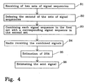
- Fig.4 An inventive method will now be described with reference to Fig.4, in which method two sets of signal sequences are received by two sets of antenna beams.
- the two sets of antenna beams are supplied by two antenna assemblies that are separated to achieve antenna diversity.
- Each of the beams in the first set of antenna beams covers the same space area as a corresponding beam in the second set, and the two beams are thus overlaid.
- Each signal sequence in a set of signal sequences corresponds to an antenna beam.
- This stage is represented by the block B1 in the flow chart of Fig.4.
- the second set of signal sequences is delayed, which in Fig.4 is represented by the block B2.
- Each signal sequence of the first set of signal sequences is then combined with a corresponding signal sequence from the delayed second set of signal sequences.
- the two combined signal sequences both derive from beams covering the same space area. This stage is represented by the block B3 in the flow sheet of Fig. 4. An artificial time dispersion is thus introduced into the combined signal sequence.
- Each combined signal sequence is separately radio received, which includes channel selection, and frequency transformation from RF to base band level. This stage is represented by the block B4 in the flow sheet of Fig. 4.
- a DOA-estimation is carried out on the basis of the received signal sequences derived from a number of antenna beams. This stage is represented by the block B5 in the flow sheet of Fig. 4.
- each combined signal which has been spread in time by the time dispersion is merged together in an equalizer or in a Rake-receiver and an estimation of the signal sent from the first mobile MS1 is then made.
- the signal estimation will be based on the radio received signal sequences derived from a number of antenna beams. This stage is represented by the block B6 in the flow sheet of Fig. 4.
- Two receiving antenna assemblies have been used in the described embodiments. This is a minimum number when antenna diversity shall be achieved. More than two antenna assemblies may be used when wishing to achieve a higher order of antenna diversity for instance. More than two antenna assemblies are also used if a combination of diversity methods shall be accomplished.
- a set of signal sequences derived from yet another antenna assembly is delayed in relation to the sets of signals derived from the other antenna assemblies.
- the signal sequences, derived from beams covering the same space area are delayed relative to one another and then combined and radio received according to the inventive method described above.
- delay elements DLM are connected to the output of these antenna assemblies and the output of each delay element DLM is connected to a combiner in the same way as the second antenna element.
- all inputs to a combiner are associated beams covering tha same space area.
- these delay elements DLM produce a delay which is significant for the antenna assembly AA1, AA2.
- Signal sequences fed to the combiner are thus delayed relative to one another.
- the relative delay between two combined signal sequences must be long enough for the equalizer or the Rake-receiver to be able to resolve.
- this delay should be in the order of 2.5 symbol times and for an equalizer in a radiosystem according to the IS 136 standard the delay should be in the order of 0.5-1 symbol time.
- the delay should be about a few chiptimes of the spreading sequence. If more signals are to be combined this difference in delay should be introduced between two consecutively delayed signals.
- antenna assemblies are referred to as being separated to achieve antenna diversity.
- antenna diversity is meant that signals are received independently via at least two antenna arrays separated spatially or by mainly orthogonal polarization directions or by a combination thereof.
- orthogonal polarization directions it is not necessary to spatially separate the antenna elements.
- antennas designed in one unit which facilitates simultaneous receiving in two separate polarization directions.
- Signals received by an antenna diversity arrangement are often improperly referred to as being uncorrelated.
- the reason why this reference is improper is because the signals concerned are sent from the first mobile station MS1 and are thus completely correlated.
- the signals are affected by different propagation paths in their travel to the receiving antenna diversity arrangement.
- the object of the antenna diversity arrangement is to decrease the degree of correlation of the influences on the received signals that is caused by the different propagation paths.
- the object of the antenna diversity arrangement is to decrease the correlation degree of the fading of the different signals and thereby reduce the possibility of all antenna assemblies being exposed to a deep fade at one and the same time.
- a common correlation factor of the fading, to which an antenna diversity arrangement is exposed is about 0.7, on a scale from 0-1, where 0 means no correlation at all, and 1 means complete correlation of the received signals.
- the low noise amplifiers LNA connected to the antenna elements AEL shown in Fig.2 and Fig.3 serve to reduce the impact of noise introduced by the receiver on the signal.
- the use of low noise amplifiers connected to the antenna elements AEL for this purpose is well known.
- the delay elements DLM connected to the second antenna assembly AA2 with reference to Fig. 2 and Fig. 3 may consist of saw-filters or fiber-cables. In either case the delay elements DLM may cause an attenuation of the received signal strength. This attenuation caused by delay elements DLM is preferably compensated for by a corresponding increase in the amplification of the low noise amplifiers LNA of the second antenna assembly AA2, to allow the signals combined at the combiner CMB to be exposed to equivalent amplification within the receiver.
- the delay elements DLM of the second antenna assembly AA2 give an amplification -D dB of the signal strength of the received signals and the low noise amplifiers LNA of the first antenna assembly AA1 give an amplification A dB to the received signals
- the amplification of low noise amplifiers LNA of the second antenna assembly AA2 should be A+D dB to compensate for the attenuation of the delay elements.
- the combiners CMB should preferably be placed near the antenna assemblies (AA1, AA2). Especially for sites where the base station BS must be placed far from the antenna assemblies (AA1, AA2) this is an improvement as the number of connecting cables is thereby reduced. The costs, weight and space for the cables required are thereby also reduced.
- the radio receiver RRC and inventive method have been used for two principles of multiple access of the radio spectra, i.e. TDMA and CDMA. It will be understood that the invention is not restricted to these two principles for multiple access, and that the invention can be applied also for other principles for multiple access.
Description
- The present invention relates to radio systems and, more particularly, to a method and apparatus for receiving radio signals with the aid of antenna beams.
- The quality of a received radio signal is affected by many natural phenomena.
- One of these phenomena is time dispersion, which is caused by a signal on its way from a transmitter being reflected by obstacles at different locations in the propagation path before reaching the receiver. The signal will arrive at the receiver at different time delays, due to the different propagation paths along which the signal travel. With the introduction of digital coded data in radio systems, time dispersed signals can be successfully restored. It is well known to a person skilled in this art to use a RAKE-receiver or an equalizer to restore a time dispersed signal.
- Another phenomenon, called fast fading or Raleigh fading, is caused by the signal being scattered on its way from the transmitter to the receiver by objects in a near distance from the transmitter or receiver. Thus, different signal versions that are slightly shifted in phase in relation to each other are received. In area spots where the phase differences are unfavorable, the sum of the received versions of the signal is very low, even close to zero. This results in a fading dip wherein the received signal virtually disappears. Fading dips occur frequently with a distance in the same order as the wavelength. For the 900 megaherz radio band the distance between two fading dips may be in the order of 15-20 cm. In case of a moving transmitter or receiver, the time that elapses between two successive fading dips as a result of fast fading depends on both the carrier frequency of the signal and the speed of the transmitter in relation to the receiver.
- One well known method of combatting fading is to provide the radio receiving station with an antenna diversity system. The system comprises two or more receiving antennas separated either spatially or by orthogonal polarization directions, or by a combination thereof. As a result fading of the signals received by each antenna are less correlated, thus decreasing the possibility of both antennas being exposed to a fading dip at one and the same time. To enable radio reception of both signals received by the antenna diversity arrangement the radio receiver station is provided with separate receiver branches for each receiving antenna.
- A third phenomenon troublesome to radio transmission is that of interference. An interfering signal can be characterized as any undesired signal received on the same channel as the desired signal. For military radio systems the most important interference to combat is jamming, i.e. intentional disturbance by the enemy. For cellular radio systems the interference problem is closely related to the capacity demand for communication. As the radio spectrum is a scarce resource, a radio frequency band given to a cellular operator must be used efficiently. For this reason the operators service area is divided into cells and radio channels used in one cell are reused in cells that have a minimum number of cells in-between. Because of the popularity of mobile phones, the demand for traffic capacity has grown rapidly. One way of handling the capacity demand is to decrease the size of the cells, thus enabling closer reuse of the channels per area unit and thereby raising the communication capacity of a given area while still preserving the frequency-reuse-factor.
- In areas where the capacity demand is high, such as in city centres and railway stations, it is often difficult to find sites for base stations. An available place for a base station may have the form of a wall on which it can be hung. In the case of sites of this nature, it is important that the radio base station is small and demands less power. The size of the radio base station is related to the power consumption, since power necessitates cooling and cooling necessitates space. The appearance of the installation is also important, for instance with respect to obtaining permission from the authorities to use a new radio base station site.
- Because of the increasing popularity of cellular systems there is a need to find new ways to combat interference, and thereby also enable higher traffic capacity. For this reason the use of adaptive antennas in radio base stations in cellular systems has been met with great interest, though not yet implemented in any commercial system. An adaptive antenna is commonly comprised of an antenna array connected to beam forming means. The adaptive antenna forms a set of antenna beams which each covers a narrow predefined space area and which together cover a wide predefined area omnidirectionally or within a sector. A signal sent from a mobile transmitter is received by each of the antenna beams, each version of the signal being separately received and thereby the angular information being maintained. The angular information is inherent in the phase difference between the different versions of the signal. An estimation of the direction to the signal source is made on the basis of the demodulated versions of the received signal. This estimated parameter is also called DOA, direction of arrival.
- To enable the estimation of the DOA, signals received by each beam must be received separatly by corresponding radio receiver branches.
- The DOA-estimation is used for the selection of one or more antenna beams, or for directing of a narrow steerable beam, for transmission in the downlink to the mobile of interest. Transmission in the chosen beam is directed to the mobile station whereby mobiles that use the same channel in other directions will be less exposed to interference. Downlink interference is thus combated by means of the adaptive antenna technique.
- One method of contending with fading and with the results of interference is to cause a radio channel frequently to change its carrier frequency. This method is called frequency hopping and is used with some success in the GSM-system. Patent publication US 08/768319, addresses in respect of frequency hopping systems a problem that resides in the coherence bandwidth being wider than the frequency bandwidth available for operation. This implies that carrier frequencies used for frequency hopping have a correlated fading. Thus the purpose of frequency hopping to combat fading cannot be achieved. The solution proposed in US 08/768319 involves producing a smaller coherence bandwidth by introducing an artificial delay spread. One way of producing the artificial delay spread is to receive a signal on two antennas, delay the signal received by a first of the antennas and then combine the delayed signal with the signal from the second of the antennas. The two combined signals are then fed to one receiver.
- WO 9623329 relates to the problem of how to achieve high antenna gain for mobiles at great distance and at the same time limit the problems of beam crossovers in a antenna arrangement with several narrow beams. The later problem occurs when the mobile station moves out of the direction of one beam and into the direction of a next beam. The solution is solved by providing two separate sets of antenna beams. The beams in the two sets are partly overlapping each other, a beam if one of the sets partly overlap two beams of the other set and the peak direction of the first set beam is in the intersection between the two beams of the other set of beams.
- US patent specification, US 5563610, addresses the use of a multi-beamforming antenna for the purpose of gaining antenna diversity based on the different beams being very narrow and covering disjunct areas. This is called angular diversity and results in the signals received in separate beams being uncorrelated. For this purpose US 5563610 teaches a receiving system in which branches from each antenna beam are distributed into two groups. In one group signals are delayed in relation to one another and then combined. Two combined signals, each derived from a corresponding of the two groups, are thus obtained and then fed to a conventional CDMA-receiver.
- In this receiver the angular information is lost after the signals have been combined. It is thus impossible to make a DOA-estimation and by means of beamforming combat downlink interference.
- The present invention addresses a problem arising when both an enabling of accurate DOA-estimation and antenna diversity shall be provided in a radio receiver comprising a limited number of radio receiver branches. The limited number of radio receiver branches results in a trade-off between the accuracy of the DOA estimation and the performance of the antenna diversity reception. If all the receiver branches are used in the DOA estimation process, the lack of protection against fading will lower the performance of the DOA estimation. If, on the other hand, the diversity gain is to be maintained by separate reception of less correlated signals, the number of beams that can be received separately will be reduced and thus also the accuracy of the DOA estimation.
- Another problem is to produce a radio base station comprising a radio receiver system that is small, has low power consumption and has antenna diversity as well as means for estimating DOA. It will be remembered that receiver branches need space and are power consuming.
- The object of the present invention is to make reception possible both by antenna diversity and by antenna beams to enable an accurate estimation of DOA, and to combat fading in a receiver that includes only a moderate number of receiver branches and thus achieve the aim of providing a radio station that is both compact and requires less power.
- The essence of the present invention is the introduction of an artificial time dispersion in a set of signals received by antenna diversity and by different antenna beams. Sets of signals received by different antenna assemblies are delayed relative to one another and signals that derive from beams covering the same space area are combined. For each of the beams in the first antenna assembly there is a beam in each of the other antenna assemblies that covers the same space area. In this way the angular information is maintained. Each combined signal is then radio received in a joint radio receiver. A DOA-estimation can be calculated on the basis of radio received signals derived from all beams. Both the natural and artificial time dispersion of the radio received signals can be restored in an equalizer or a Rake-receiver. By the inventive combination of signals the energy from each of the combined signals is maintained until the signals reach the equalizer or Rake-receiver. The energies from the different time dispersed signals are merged together in the equalizer or in the Rake-receiver. If the energy of one of the combined signals is low temporarily due to a fading dip at the corresponding receiving antenna the energy of the signal received by the other antenna will compensate for the fading dip.
- More precisely, the present invention solves the aforementioned problems by means of a method in which signals are received by at least two antenna assemblies that are separated to achieve antenna diversity, i.e. the antenna assemblieas are separated spatially or by different polarization directions. Each of the antenna assemblies generates a set of antenna beams. The antenna assemblies are constructed so as to generate mutually corresponding sets of antenna beams, i.e. the beams have corresponding angular coverages and a particular area is covered by two beams, one from each of the antenna assemblies. Signals received by separate antenna assemblies in corresponding antenna beams are then mutually combined after having been delayed in relation to one another. An artificial multipath propagation is thus created in respect of the combined signal. The combined signal is then fed to one radio receiver branch for frequency transformation from RF to a lower frequency and demodulation, whereupon the artificial time dispersion can be restored by digital signal processing in an equalizer or a RAKE-receiver for instance. A DOA-estimation can be calculated on the basis of the outputs from several radio receiver branches to which signals are fed from separate beams.
- The present invention is also related to a radio receiver system which solves the aforementioned problems. The radio receiver system comprises at least two antenna assemblies which are mutually separated to achieve antenna diversity. Each of the antenna assemblies generates a set of antenna beams, where each beam covers a narrow space area and the beams together cover an specific area omnidirectionally or within whithin a sector. The different sets of beams correspond to each other, and one space area is covered by a beam from each of the antenna assemblies. Delay elements are connected to all but one of the antenna assemblies. The delay elements delay signals received by a corresponding antenna assembly. The delay is given a separate value for each antenna assembly. A number of combiners are connected to the delay elements and also to that antenna assembly which is without delay element. Each of the combiners receives from each of the antenna assemblies signals from corresponding beams. Each combiner output is connected to a corresponding receiver branch.
- The invention constitutes an improvement in the known art by virtue of the fact that one radio receiver branch can be fed with signals from several antenna assemblies, whereafter the signals can be restored. Thus the required number of radio receiver branches to achieve both antenna diversity gain and to enable the calculation of an accurate DOA estimation is limited to correspond to the number of beams in the set of antenna beams. This enable both the size of the radio receiver and its power consumption to be reduced.
- A further improvement is jound in respect of sites in which a base station comprising the inventive radio receiver is placed on the ground and the antenna assemblies are mounted on a mast. The weight of the cables connecting the base station with the antenna assemblies is an important factor in respect of mast dimensions. The number of cables connecting the base station to the antenna assemblies can be reduced by coupling the combiners close to the antenna assemblies. Thereby the weight of the cables is reduced which will allow a mast to have smaller dimensions and therewith lower the cost of the mast as well as the cables.
- The invention will now be described in more detail with reference to preferred embodiments thereof and also with reference to the accompanying drawings.
-
- Fig. 1 illustrates two mobile stations and a radio base station comprising two antenna assemblies.
- Fig. 2 is a block schematic illustrating a radio receiver according to the invention.
- Fig. 3 is a block schematic illustrating another radio receiver according to the invention.
- Fig. 4 is a flow diagram illustrating a radio receiving method.
- In Fig. 1 there is shown two mobile stations MS1 and MS2 and a base station BS that includes an inventive radio receiver. A radio channel CH is used for communication between the first mobile station MS1 and the radio base station BS. The radio channel CH is also used by the second mobile station MS2 for communication with another base station, not shown in Fig. 1.
- The radio base station BS is equipped with two antenna assemblies AA1, AA2. The antenna assemblies AA1, AA2 are separated to achieve antenna diversity. Both cover a 120° sector with a number of beams. The first antenna assembly AA1 generates a first set of antenna beams SAB1 and the second antenna assembly AA2 generates a second set of antenna beams SAB2. For each of the beams in the first set SAB1 there is a corresponding beam in the second set of beams SAB2 covering the same space area, i.e. the two beams are overlaid. The space area in which the first mobile MS1 is placed is covered by a beam in each of the sets of beams SAB1, SAB2, and the direction to the second mobile MS2 is covered by an other beam.
- Signals derived from different beams are separately received in the receiver, thereby maintaining the angular information. A DOA estimation estimating the direction to the first mobile station MS1 can be made with the aid of these signals.
- Downlink interference is decreased by transmission in a beam directed to the first mobile station MS1, thereby improving the downlink quality for the second mobile station MS2. The downlink beam is selected on the basis of the DOA estimation of the first mobile station MS1.
- The antenna diversity arrangement improves the uplink quality by reducing the risk of both the antenna assemblies being exposed to a deep fading dip at the same time.
- An embodiment of the inventive radio receiver for a TDMA system will be described with reference to Fig. 2. The radio receiver RRC comprises two antenna assemblies AA1, AA2. Each of the antenna assemblies AA1, AA2 comprises an antenna array AAR formed by a number of antenna elements AEL, low noise amplifiers LNA connected to the antenna elements AEL, and beam forming means BM with connections from the low noise amplifiers LNA. The antenna elements AEL of the first antenna assembly AA1 are given an orthogonal polarization direction relative to the polarization direction of the antenna elements AEL of the second antenna assembly AA2.
- In this embodiment the beam forming means BM consists of a Butler matrix. The Butler matrix BM has a number of outputs, each corresponding to an antenna beam.
- The radio receiver RRC also comprises a number of delay elements DLM, a number of combiners CMB, a number of radio receiver branches RX, a DOA estimator DP and an equalization and signal estimation unit EqSE.
- Each output of the Butler matrix BM of the second antenna assembly AA2 is connected to a corresponding delay element DLM. Each output of the delay elements DLM is connected to a corresponding combiner CMB. Each combiner CMB also has an other connection from the Butler matrix BM of the first antenna assembly AA1. The two inputs to a combiner corresponds to beams covering corresponding space area.
- The output of each combiner CMB is connected to a corresponding radio receiver branch RX. The radio receiver branch RX comprises channel selection, and frequency transformation from RF to base band.
- Outputs of all the radio receiver branches RX are connected to the equalization and signal estimation unit EqSE. In this embodiment the equalization unit comprises an MLSE, Maximum Likelihood Sequence Estimation, and means for combination of received signals derived from different beams.
- The outputs of the radio receiver branches RX are also connected to the DOA-estimator DP. A DOA-estimator is well known to a person skilled in the art, see e.g. "Direction-of-arrival estimation and...", by authors Viberg, Ottersten and Kailat, in proc. 23rd Asilomar Conf. Signal, Syst., Comp., Nov 1989.
- Another embodiment of the inventive radio receiver RRC for use in a direct sequence CDMA-system will now be described with reference to Fig. 3. The inventive radio receiver RRC comprises two antenna assemblies AA1, AA2. The antenna assemblies AA1, AA2 comprise the same parts as the antenna assemblies AA1, AA2 in the earlier described embodiment with reference to Fig. 2. A difference, however is, that the two antenna arrays AAR are not given orthogonal polarization directions but are spatially separated by approximately 10-20 wavelengths.
- The radio receiver RRC also comprises a number of delay elements DLM, a number of combiners CMB, a number of radio receiver branches RX, a Rake-receiver RAKE, and a DOA-estimator DP.
- The antenna assemblies AA1, AA2 have a number of outputs each corresponding to a beam. Each of the outputs of the second antenna assemblies is connected to a corresponding delay element DLM. Each of the outputs of the delay elements DLM is connected to a corresponding combiner CMB. To each of these combiners CMB is also connected an output from the first antenna assembly AA1. The beams corresponding to the two inputs at the combiner CMB cover the same space area.
- The outputs from the combiners CMB are connected to corresponding radio receiver branches RX. The radio receiver branches RX have been described with reference to the Fig. 2 embodiment.
- The outputs from the radio receiver branches RX are connected to a Rake-receiver RAKE. The Rake-receiver RAKE comprises means for combining signals radio received by different radio receiver branches RX, e.g. through Maximum Ratio Combining, MRC. The Rake-receiver RAKE performs Rake-combining of delayed signals. Both Rake-combining and MRC are teqniques well known to a person skilled in the art.
- The outputs of the radio receiver branches RX are also connected to a DOA estimator DP. For further discription of DOA-estimation in a Rake-receiver, see the document, Ayman P Naguib, Adaptive Antennas for CDMA Wireless Networks, PhD Thesis, Dep of EE Stanford University.
- The described embodiments have illustrated two methods of obtaining antenna diversity, by spatial separation and by orthogonal polarization direction of the antenna elements AEL respectively. The multiple access methods, TDMA or CDMA, can use both methods or a combination of the two methods to obtain antenna diversity.
- An inventive method will now be described with reference to Fig.4, in which method two sets of signal sequences are received by two sets of antenna beams. The two sets of antenna beams are supplied by two antenna assemblies that are separated to achieve antenna diversity. Each of the beams in the first set of antenna beams covers the same space area as a corresponding beam in the second set, and the two beams are thus overlaid. Each signal sequence in a set of signal sequences corresponds to an antenna beam. This stage is represented by the block B1 in the flow chart of Fig.4.
- The second set of signal sequences is delayed, which in Fig.4 is represented by the block B2.
- Each signal sequence of the first set of signal sequences is then combined with a corresponding signal sequence from the delayed second set of signal sequences. The two combined signal sequences both derive from beams covering the same space area. This stage is represented by the block B3 in the flow sheet of Fig. 4. An artificial time dispersion is thus introduced into the combined signal sequence.
- Each combined signal sequence is separately radio received, which includes channel selection, and frequency transformation from RF to base band level. This stage is represented by the block B4 in the flow sheet of Fig. 4.
- A DOA-estimation is carried out on the basis of the received signal sequences derived from a number of antenna beams. This stage is represented by the block B5 in the flow sheet of Fig. 4.
- The energy of each combined signal which has been spread in time by the time dispersion is merged together in an equalizer or in a Rake-receiver and an estimation of the signal sent from the first mobile MS1 is then made. By use of a known combining method, for example, MRC, the signal estimation will be based on the radio received signal sequences derived from a number of antenna beams. This stage is represented by the block B6 in the flow sheet of Fig. 4.
- Two receiving antenna assemblies have been used in the described embodiments. This is a minimum number when antenna diversity shall be achieved. More than two antenna assemblies may be used when wishing to achieve a higher order of antenna diversity for instance. More than two antenna assemblies are also used if a combination of diversity methods shall be accomplished. According to the inventive method a set of signal sequences derived from yet another antenna assembly is delayed in relation to the sets of signals derived from the other antenna assemblies. The signal sequences, derived from beams covering the same space area, are delayed relative to one another and then combined and radio received according to the inventive method described above.
- If a third or more antenna assemblies AA1, AA2 are added to the inventive radio receiver RRC, delay elements DLM are connected to the output of these antenna assemblies and the output of each delay element DLM is connected to a combiner in the same way as the second antenna element. Thus, all inputs to a combiner are associated beams covering tha same space area. For each of the antenna assembles AA1, AA2 to which delay elements DLM are connected these delay elements DLM produce a delay which is significant for the antenna assembly AA1, AA2. Signal sequences fed to the combiner are thus delayed relative to one another.
- The relative delay between two combined signal sequences must be long enough for the equalizer or the Rake-receiver to be able to resolve. For an equalizer in the GSM-system this delay should be in the order of 2.5 symbol times and for an equalizer in a radiosystem according to the IS 136 standard the delay should be in the order of 0.5-1 symbol time. For a Rake-receiver, the delay should be about a few chiptimes of the spreading sequence. If more signals are to be combined this difference in delay should be introduced between two consecutively delayed signals.
- In this context the antenna assemblies are referred to as being separated to achieve antenna diversity. By antenna diversity is meant that signals are received independently via at least two antenna arrays separated spatially or by mainly orthogonal polarization directions or by a combination thereof. For receiving by orthogonal polarization directions it is not necessary to spatially separate the antenna elements. In fact there are antennas designed in one unit which facilitates simultaneous receiving in two separate polarization directions.
- Signals received by an antenna diversity arrangement are often improperly referred to as being uncorrelated. The reason why this reference is improper is because the signals concerned are sent from the first mobile station MS1 and are thus completely correlated. However, the signals are affected by different propagation paths in their travel to the receiving antenna diversity arrangement. The object of the antenna diversity arrangement is to decrease the degree of correlation of the influences on the received signals that is caused by the different propagation paths. Expressed differently, the object of the antenna diversity arrangement is to decrease the correlation degree of the fading of the different signals and thereby reduce the possibility of all antenna assemblies being exposed to a deep fade at one and the same time.
- In practice it is not possible to achieve completely uncorrelated fading of the signals received by the antenna diversity arrangement. One reason is because the antenna arrays cannot be spaced too far apart. However, this does not present a problem because a moderate reduction of the correlation of the fading is enough to make a significant improvement in the uplink radio quality. In practice a common correlation factor of the fading, to which an antenna diversity arrangement is exposed, is about 0.7, on a scale from 0-1, where 0 means no correlation at all, and 1 means complete correlation of the received signals.
- The low noise amplifiers LNA connected to the antenna elements AEL shown in Fig.2 and Fig.3 serve to reduce the impact of noise introduced by the receiver on the signal. The use of low noise amplifiers connected to the antenna elements AEL for this purpose is well known.
- The delay elements DLM connected to the second antenna assembly AA2 with reference to Fig. 2 and Fig. 3 may consist of saw-filters or fiber-cables. In either case the delay elements DLM may cause an attenuation of the received signal strength. This attenuation caused by delay elements DLM is preferably compensated for by a corresponding increase in the amplification of the low noise amplifiers LNA of the second antenna assembly AA2, to allow the signals combined at the combiner CMB to be exposed to equivalent amplification within the receiver. If the delay elements DLM of the second antenna assembly AA2 give an amplification -D dB of the signal strength of the received signals and the low noise amplifiers LNA of the first antenna assembly AA1 give an amplification A dB to the received signals, the amplification of low noise amplifiers LNA of the second antenna assembly AA2 should be A+D dB to compensate for the attenuation of the delay elements.
- In a base station BS comprising the inventive radio receiver RRC, the combiners CMB should preferably be placed near the antenna assemblies (AA1, AA2). Especially for sites where the base station BS must be placed far from the antenna assemblies (AA1, AA2) this is an improvement as the number of connecting cables is thereby reduced. The costs, weight and space for the cables required are thereby also reduced.
- In the aforedescribed embodiments, the radio receiver RRC and inventive method have been used for two principles of multiple access of the radio spectra, i.e. TDMA and CDMA. It will be understood that the invention is not restricted to these two principles for multiple access, and that the invention can be applied also for other principles for multiple access.
Claims (19)
- A receiver system (RRC) comprising,
at least two antenna assemblies (AA1, AA2) arranged for achieving antenna diversity and each providing a set of antenna beams (SAB1, SAB2) arranged such that a space area covered by an antenna beam of a first of the antenna assemblies is substantially also covered by an antenna beam of a second of the antenna assemblies wherein the antenna assemblies are further arranged to provide the signal received in respective of the antenna beams at respective outputs,
delay elements (DLM) connected to the outputs of at least one of said antenna assemblies (AA1, AA2);
combiner devices (CMB), each with an input from the first antenna assembly and an input from the second antenna assembly, wherein at least one of said inputs is connected via said delay elements (DLM) wherein each of said combiner devices is adapted to combine the received signals derived from the beams substantially covering the same space area; and
radio receiver branches (RX) each connected to an output of a corresponding combiner device and leading to a radio receiver. - A receiver system according to Claim 1 wherein the antenna assemblies (AA1, AA2) are spatially separated to achieve said antenna diversity.
- A receiver system according to Claim 1 wherein the antenna assemblies (AA1, AA2) have different polarization directions to achieve said antenna diversity.
- A receiver system according to Claim 1 wherein the antenna assemblies (AA1, AA2) are separated by a combination of spatial and polarization means to achieve said antenna diversity.
- A receiver system according to Claim 2 wherein the spatial separation between the antenna assemblies (AA1, AA2) is in the order of 10-20 wavelengths.
- A receiver system according to Claim 1, 2 or 3 wherein the delay elements (DLM) are adapted to produce a delay that is specific for each connected antenna assembly (AA1, AA2).
- A receiver system according to Claim 6, wherein the difference in delay corresponding to two antenna assemblies (AA1, AA2) is at least half a symbol time for a TDMA system.
- A receiver system according to Claim 6, wherein the difference in delay corresponding to two antenna assemblies (AA1, AA2) is at least one chip time of a CDMA spreading sequence.
- A receiver system according to Claim 1, 2 or 6, wherein, there is a number of outputs from each of the antenna assemblies (AA1, AA2), each output corresponding to an antenna beam, and wherein each of the outputs of of the antenna assemblies (AA1, AA2), with an optional exception of one of the antenna assemblies, are connected to a corresponding delay element (DLM).
- A receiver system according to Claim 1, 2 or 6 wherein, the radio receiver system (RRC) includes two antenna assemblies (AA1, AA2), delay elements (DLM) connected to a second of said antenna elements (AA2), a number of combiners (CMB) each with an input connected to the first antenna assembly (AA1) and another input connected to one of said delay elements, both inputs corresponding to antenna beams mainly covering the same space area.
- A receiver system according to Claim 1, 2, 3, 6 or 10, wherein,
a channel estimator (EqSE) is provided for computing channel estimation and signal estimation, said device having an input with connections from said receiver branches (RX). - A receiver system according to Claim 1, 2, 3, 6 or 10 comprising
a DOA-estimator (DP) for computing a DOA estimate and having an input with connections from said receiver branches (RX). - A receiver system according to Claim 1, 2, 6, 10 or 11, wherein,
said radio receiver branches (RX) comprise a channel selection filter, and a frequency mixer that transforms the channel from RF to a lower frequency. - A receiver system according to Claim 1, 2, 6, 10 or 11, wherein,
each of said antenna assemblies (AA1, AA2) comprises an array (AAR) of antenna elements (AEL), amplifiers (LNA) connected to each antenna element (AEL) and beam forming means (BM). - A receiver system according to Claim 14 wherein, the amplifiers (LNA) are arranged to provide an amplification to compensate for attenuation caused by the delay elements (DLM).
- A radio receiving method comprising,
providing a first set of antenna beams (SAB1),
providing a second set of antenna beams (SAB2), arranging the first set and the second set of antenna beams for achieving antenna diversity and further
arranging said sets of antenna beams such that an space area covered by an antenna beam of the first set is also covered by an antenna beam of the second set,
characterized by the further steps of:a) receiving (B1) by said first set of antenna beams (SAB1) a first set of signals and by said second set of antenna beams (SAB2) a second set of signals, each signal in the sets being derived from a corresponding antenna beam,b) delaying (B2) the second set of signals,c) combining (B3) said first set of signals with said delayed second set of signals, each combination comprises a signal from said first set of signals and a signal from said delayed second set of signals, said signals both being received by covering substantially the same space area,d) radio receiving (B4) the combined signals. - Method according to Claim 16 characterized by the steps of:e) reducing correlation between the fading pattern of said first set of signals and the fading pattern of said second set of signals by means of antenna diversity.
- Method according to Claim 16 or 17 wherein step d comprises channel selection, and transformation of the received signal from RF to a lower frequency.
- Method according to Claim 16 or 17 comprising the further step of:h) estimating (B5) DOA on the basis of signals received after carrying out step d.
Applications Claiming Priority (3)
| Application Number | Priority Date | Filing Date | Title |
|---|---|---|---|
| SE9704282A SE513656C2 (en) | 1997-11-21 | 1997-11-21 | Method and apparatus for receiving radio signals by means of antenna lobes |
| SE9704282 | 1997-11-21 | ||
| PCT/SE1998/001967 WO1999027659A1 (en) | 1997-11-21 | 1998-10-30 | Method and apparatus for receiving radio signals |
Publications (2)
| Publication Number | Publication Date |
|---|---|
| EP1032983A1 EP1032983A1 (en) | 2000-09-06 |
| EP1032983B1 true EP1032983B1 (en) | 2006-01-04 |
Family
ID=20409073
Family Applications (1)
| Application Number | Title | Priority Date | Filing Date |
|---|---|---|---|
| EP98954881A Expired - Lifetime EP1032983B1 (en) | 1997-11-21 | 1998-10-30 | Method and apparatus for receiving radio signals |
Country Status (12)
| Country | Link |
|---|---|
| US (1) | US6650910B1 (en) |
| EP (1) | EP1032983B1 (en) |
| JP (1) | JP4280414B2 (en) |
| KR (1) | KR20010032335A (en) |
| CN (1) | CN1150688C (en) |
| AU (1) | AU748180B2 (en) |
| BR (1) | BR9814233A (en) |
| CA (1) | CA2311338A1 (en) |
| DE (1) | DE69833130T2 (en) |
| SE (1) | SE513656C2 (en) |
| TW (1) | TW407384B (en) |
| WO (1) | WO1999027659A1 (en) |
Families Citing this family (34)
| Publication number | Priority date | Publication date | Assignee | Title |
|---|---|---|---|---|
| JP2001203620A (en) * | 2000-01-19 | 2001-07-27 | Matsushita Electric Ind Co Ltd | Wireless base station device and wireless communication method |
| US7016649B1 (en) * | 2000-03-17 | 2006-03-21 | Kathrein-Werke Kg | Space-time and space-frequency hopping for capacity enhancement of mobile data systems |
| GB0015511D0 (en) * | 2000-06-23 | 2000-08-16 | Univ Surrey | Antenna combiners |
| ATE289451T1 (en) | 2000-12-29 | 2005-03-15 | Nokia Corp | BASE STATION, BASE STATION MODULE AND METHOD FOR ESTIMATING PARAMETERS FOR UPWARD SIGNALS |
| US7058145B2 (en) * | 2001-06-04 | 2006-06-06 | Qualcomm, Inc. | Diversity gain with a compact antenna |
| KR100459133B1 (en) * | 2002-01-04 | 2004-12-03 | 엘지전자 주식회사 | Apparatus and method for transmitting signal in multiple input multiple output system |
| US7327798B2 (en) | 2001-10-19 | 2008-02-05 | Lg Electronics Inc. | Method and apparatus for transmitting/receiving signals in multiple-input multiple-output communication system provided with plurality of antenna elements |
| US8045935B2 (en) | 2001-12-06 | 2011-10-25 | Pulse-Link, Inc. | High data rate transmitter and receiver |
| US7317756B2 (en) | 2001-12-06 | 2008-01-08 | Pulse-Link, Inc. | Ultra-wideband communication apparatus and methods |
| US20050152483A1 (en) * | 2001-12-06 | 2005-07-14 | Ismail Lakkis | Systems and methods for implementing path diversity in a wireless communication network |
| TW521454B (en) * | 2002-03-26 | 2003-02-21 | Far Eastone Telecomm Co Ltd | The FBFN correction method for the beam pointing error of the LMDS system and device thereof |
| JP2003338804A (en) * | 2002-05-22 | 2003-11-28 | Nec Corp | Path search apparatus and method, and antenna array receiving apparatus using the same |
| JP2005260502A (en) * | 2004-03-10 | 2005-09-22 | Nec Corp | Communication equipment and communication control method |
| US6992622B1 (en) | 2004-10-15 | 2006-01-31 | Interdigital Technology Corporation | Wireless communication method and antenna system for determining direction of arrival information to form a three-dimensional beam used by a transceiver |
| US20090289864A1 (en) * | 2004-12-13 | 2009-11-26 | Anders Derneryd | Antenna Arrangement And A Method Relating Thereto |
| CN100388846C (en) * | 2005-07-08 | 2008-05-14 | 中兴通讯股份有限公司 | Downlink beamforming method in mobile communication intelligent antenna system |
| DK2280495T3 (en) * | 2005-09-01 | 2012-04-23 | Sharp Kk | Method of wireless transmission |
| US7609753B1 (en) * | 2005-09-13 | 2009-10-27 | Rockwell Collins, Inc. | Link 16 radio receiver using antenna diversity |
| EA016627B1 (en) * | 2005-10-31 | 2012-06-29 | Шарп Кабусики Кайся | Wireless transmitter |
| CN101346919B (en) | 2005-10-31 | 2013-01-30 | 夏普株式会社 | Radio transmitter, radio communication system, and radio transmission method |
| EA012005B1 (en) * | 2005-12-20 | 2009-06-30 | Шарп Кабусики Кайся | Transmitter |
| US8165537B2 (en) * | 2005-12-26 | 2012-04-24 | Sharp Kabushiki Kaisha | Wireless transmitter and wireless transmission method |
| US8055300B2 (en) * | 2007-08-29 | 2011-11-08 | Telefonaktiebolaget Lm Ericsson (Publ) | System and method for indoor coverage of user equipment terminals |
| CN101499835B (en) * | 2008-01-31 | 2012-11-07 | 电信科学技术研究院 | Downlink transmission processing method and apparatus based on double polarization array antenna |
| US8412093B2 (en) * | 2008-10-22 | 2013-04-02 | Mediatek Inc. | Receiver applying channel selection filter for receiving satellite signal and receiving method thereof |
| US8588805B2 (en) * | 2008-12-13 | 2013-11-19 | Broadcom Corporation | Receiver utilizing multiple radiation patterns to determine angular position |
| US8831523B2 (en) | 2009-06-18 | 2014-09-09 | Qualcomm Incorporated | Methods and apparatus for beamforming for femtocells |
| US8073399B2 (en) * | 2009-06-23 | 2011-12-06 | Lockheed Martin Corporation | Device and method for matrixed adaptive equalizing for communication receivers configured to an antenna array |
| RU2491717C2 (en) * | 2010-05-04 | 2013-08-27 | Попик Павел Иванович | Method of increasing signal-to-noise level (ratio) using "disturbance damping principle" |
| US9124333B1 (en) * | 2014-10-17 | 2015-09-01 | Sprint Communications Company L.P. | Improving uplink performance for a beam-forming antenna configuration |
| US10564249B2 (en) * | 2015-07-17 | 2020-02-18 | Huawei Technologies Canada Co., Ltd. | Waveguide structure for use in direction-of-arrival determination system and associated determination method |
| US11082102B2 (en) | 2017-09-28 | 2021-08-03 | Hitachi Kokusai Electric Inc. | Beam forming antenna |
| CN108414965B (en) * | 2018-06-05 | 2021-04-30 | 电子科技大学 | Signal source DOA estimation method of space-time structure based on pre-delay removal module |
| US11658406B2 (en) * | 2019-06-18 | 2023-05-23 | The Boeing Company | Tapered wall radome |
Citations (1)
| Publication number | Priority date | Publication date | Assignee | Title |
|---|---|---|---|---|
| WO1996023329A1 (en) * | 1995-01-27 | 1996-08-01 | Hazeltine Corporation | High gain antenna systems for cellular use |
Family Cites Families (14)
| Publication number | Priority date | Publication date | Assignee | Title |
|---|---|---|---|---|
| US5515378A (en) | 1991-12-12 | 1996-05-07 | Arraycomm, Inc. | Spatial division multiple access wireless communication systems |
| US5507035A (en) * | 1993-04-30 | 1996-04-09 | International Business Machines Corporation | Diversity transmission strategy in mobile/indoor cellula radio communications |
| US5621752A (en) | 1994-06-23 | 1997-04-15 | Qualcomm Incorporated | Adaptive sectorization in a spread spectrum communication system |
| RU2152688C1 (en) * | 1995-01-20 | 2000-07-10 | Сименс АГ | Method for signal transmission between mobile and stationary transmitting-receiving stations of wireless communication systems and device which implements said method |
| US5581260A (en) | 1995-01-27 | 1996-12-03 | Hazeltine Corporation | Angular diversity/spaced diversity cellular antennas and methods |
| GB9501670D0 (en) * | 1995-01-27 | 1996-04-03 | Thorn Emi Electronics Ltd | Method and apparatus for estimating radar signal polarisation |
| US5649287A (en) * | 1995-03-29 | 1997-07-15 | Telefonaktiebolaget Lm Ericsson | Orthogonalizing methods for antenna pattern nullfilling |
| FI105430B (en) | 1995-05-24 | 2000-08-15 | Nokia Networks Oy | Base station equipment and method for directing antenna beam |
| FI105513B (en) * | 1995-05-24 | 2000-08-31 | Nokia Networks Oy | Reception procedure and recipients |
| FI105512B (en) * | 1995-05-24 | 2000-08-31 | Nokia Networks Oy | A method for providing an angular repetition and a base station apparatus |
| US5563610A (en) * | 1995-06-08 | 1996-10-08 | Metawave Communications Corporation | Narrow beam antenna systems with angular diversity |
| US6023607A (en) * | 1997-05-30 | 2000-02-08 | Nokia Telecommunication Oy | Radio system and a call setup method |
| US5926503A (en) * | 1997-08-27 | 1999-07-20 | Motorola, Inc. | DS-CDMA receiver and forward link diversity method |
| US6275482B1 (en) * | 1997-10-28 | 2001-08-14 | Qwest Communications International Inc. | Combined angular, spatial, and temporal diversity for mobile radio system |
-
1997
- 1997-11-21 SE SE9704282A patent/SE513656C2/en not_active IP Right Cessation
-
1998
- 1998-10-30 CA CA002311338A patent/CA2311338A1/en not_active Abandoned
- 1998-10-30 KR KR1020007005551A patent/KR20010032335A/en not_active Application Discontinuation
- 1998-10-30 JP JP2000522686A patent/JP4280414B2/en not_active Expired - Fee Related
- 1998-10-30 AU AU11818/99A patent/AU748180B2/en not_active Ceased
- 1998-10-30 EP EP98954881A patent/EP1032983B1/en not_active Expired - Lifetime
- 1998-10-30 DE DE69833130T patent/DE69833130T2/en not_active Expired - Lifetime
- 1998-10-30 CN CNB988113678A patent/CN1150688C/en not_active Expired - Fee Related
- 1998-10-30 BR BR9814233-0A patent/BR9814233A/en not_active IP Right Cessation
- 1998-10-30 WO PCT/SE1998/001967 patent/WO1999027659A1/en active IP Right Grant
- 1998-11-04 TW TW087118355A patent/TW407384B/en not_active IP Right Cessation
- 1998-11-20 US US09/196,117 patent/US6650910B1/en not_active Expired - Lifetime
Patent Citations (1)
| Publication number | Priority date | Publication date | Assignee | Title |
|---|---|---|---|---|
| WO1996023329A1 (en) * | 1995-01-27 | 1996-08-01 | Hazeltine Corporation | High gain antenna systems for cellular use |
Also Published As
| Publication number | Publication date |
|---|---|
| DE69833130D1 (en) | 2006-03-30 |
| SE9704282L (en) | 1999-05-22 |
| JP2001524773A (en) | 2001-12-04 |
| CN1150688C (en) | 2004-05-19 |
| DE69833130T2 (en) | 2006-08-31 |
| US6650910B1 (en) | 2003-11-18 |
| EP1032983A1 (en) | 2000-09-06 |
| SE9704282D0 (en) | 1997-11-21 |
| WO1999027659A1 (en) | 1999-06-03 |
| TW407384B (en) | 2000-10-01 |
| AU1181899A (en) | 1999-06-15 |
| CN1279845A (en) | 2001-01-10 |
| BR9814233A (en) | 2000-10-03 |
| KR20010032335A (en) | 2001-04-16 |
| AU748180B2 (en) | 2002-05-30 |
| SE513656C2 (en) | 2000-10-16 |
| CA2311338A1 (en) | 1999-06-03 |
| JP4280414B2 (en) | 2009-06-17 |
Similar Documents
| Publication | Publication Date | Title |
|---|---|---|
| EP1032983B1 (en) | Method and apparatus for receiving radio signals | |
| US5649287A (en) | Orthogonalizing methods for antenna pattern nullfilling | |
| US6347234B1 (en) | Practical space-time radio method for CDMA communication capacity enhancement | |
| US7043275B2 (en) | Radio communication apparatus using adaptive antenna | |
| US20190058523A1 (en) | Mobile networking method and system for minimizing interference | |
| US20050075139A1 (en) | Method and system for improving communication | |
| KR101011751B1 (en) | Undulating transmit patterns for multiple simultaneous transmitters to support signal separation at a receiver | |
| WO1997002666A1 (en) | Reception method and base station receiver | |
| KR101015933B1 (en) | Undulating transmit patterns to support signal separation at a receiver | |
| US20020034270A1 (en) | Receiver | |
| US6275482B1 (en) | Combined angular, spatial, and temporal diversity for mobile radio system | |
| JP2918873B1 (en) | Array antenna device for spread spectrum communication | |
| US6956841B1 (en) | Receiver and method of receiving a desired signal | |
| US6611511B1 (en) | Cellular telephone communication system using sector splitting for improved performance | |
| CN114785381A (en) | Interference elimination method based on forward link model of multi-beam satellite system | |
| US20040009791A1 (en) | Radio communication device,radio communication method, and radio base station device | |
| Hugl et al. | Transformation based downlink beamforming techniques for frequency division duplex systems | |
| JP3337274B2 (en) | Mobile communication system | |
| Ottersten et al. | Base-station antenna arrays in mobile communications | |
| EP1063781A1 (en) | Method of finding the best transmission channels for a CDMA signal, and components therefor | |
| Ottersten | Antenna Arrays in Mobile Communications | |
| Wells | Adaptive antennas for frequency re-use in every cell of a gsm network | |
| orn Ottersten et al. | Base-Station Antenna Arrays in Mobile Communications | |
| MXPA97007231A (en) | Antenna lobulo an |
Legal Events
| Date | Code | Title | Description |
|---|---|---|---|
| PUAI | Public reference made under article 153(3) epc to a published international application that has entered the european phase |
Free format text: ORIGINAL CODE: 0009012 |
|
| 17P | Request for examination filed |
Effective date: 20000408 |
|
| AK | Designated contracting states |
Kind code of ref document: A1 Designated state(s): DE FR GB IT NL |
|
| RAP1 | Party data changed (applicant data changed or rights of an application transferred) |
Owner name: TELEFONAKTIEBOLAGET LM ERICSSON (PUBL) |
|
| 17Q | First examination report despatched |
Effective date: 20041019 |
|
| GRAP | Despatch of communication of intention to grant a patent |
Free format text: ORIGINAL CODE: EPIDOSNIGR1 |
|
| RTI1 | Title (correction) |
Free format text: METHOD AND APPARATUS FOR RECEIVING RADIO SIGNALS |
|
| GRAS | Grant fee paid |
Free format text: ORIGINAL CODE: EPIDOSNIGR3 |
|
| GRAA | (expected) grant |
Free format text: ORIGINAL CODE: 0009210 |
|
| AK | Designated contracting states |
Kind code of ref document: B1 Designated state(s): DE FR GB IT NL |
|
| PG25 | Lapsed in a contracting state [announced via postgrant information from national office to epo] |
Ref country code: NL Free format text: LAPSE BECAUSE OF FAILURE TO SUBMIT A TRANSLATION OF THE DESCRIPTION OR TO PAY THE FEE WITHIN THE PRESCRIBED TIME-LIMIT Effective date: 20060104 Ref country code: IT Free format text: LAPSE BECAUSE OF FAILURE TO SUBMIT A TRANSLATION OF THE DESCRIPTION OR TO PAY THE FEE WITHIN THE PRESCRIBED TIME-LIMIT;WARNING: LAPSES OF ITALIAN PATENTS WITH EFFECTIVE DATE BEFORE 2007 MAY HAVE OCCURRED AT ANY TIME BEFORE 2007. THE CORRECT EFFECTIVE DATE MAY BE DIFFERENT FROM THE ONE RECORDED. Effective date: 20060104 |
|
| REG | Reference to a national code |
Ref country code: GB Ref legal event code: FG4D |
|
| REF | Corresponds to: |
Ref document number: 69833130 Country of ref document: DE Date of ref document: 20060330 Kind code of ref document: P |
|
| NLV1 | Nl: lapsed or annulled due to failure to fulfill the requirements of art. 29p and 29m of the patents act | ||
| ET | Fr: translation filed | ||
| PLBE | No opposition filed within time limit |
Free format text: ORIGINAL CODE: 0009261 |
|
| STAA | Information on the status of an ep patent application or granted ep patent |
Free format text: STATUS: NO OPPOSITION FILED WITHIN TIME LIMIT |
|
| 26N | No opposition filed |
Effective date: 20061005 |
|
| REG | Reference to a national code |
Ref country code: FR Ref legal event code: PLFP Year of fee payment: 18 |
|
| PGFP | Annual fee paid to national office [announced via postgrant information from national office to epo] |
Ref country code: GB Payment date: 20151027 Year of fee payment: 18 Ref country code: IT Payment date: 20151026 Year of fee payment: 18 Ref country code: DE Payment date: 20151028 Year of fee payment: 18 |
|
| PGFP | Annual fee paid to national office [announced via postgrant information from national office to epo] |
Ref country code: FR Payment date: 20151019 Year of fee payment: 18 |
|
| REG | Reference to a national code |
Ref country code: DE Ref legal event code: R119 Ref document number: 69833130 Country of ref document: DE |
|
| GBPC | Gb: european patent ceased through non-payment of renewal fee |
Effective date: 20161030 |
|
| REG | Reference to a national code |
Ref country code: FR Ref legal event code: ST Effective date: 20170630 |
|
| PG25 | Lapsed in a contracting state [announced via postgrant information from national office to epo] |
Ref country code: FR Free format text: LAPSE BECAUSE OF NON-PAYMENT OF DUE FEES Effective date: 20161102 Ref country code: DE Free format text: LAPSE BECAUSE OF NON-PAYMENT OF DUE FEES Effective date: 20170503 Ref country code: GB Free format text: LAPSE BECAUSE OF NON-PAYMENT OF DUE FEES Effective date: 20161030 |
|
| PG25 | Lapsed in a contracting state [announced via postgrant information from national office to epo] |
Ref country code: IT Free format text: LAPSE BECAUSE OF NON-PAYMENT OF DUE FEES Effective date: 20161030 |