EP1033098A1 - Cushion and seat each having net-like skin - Google Patents
Cushion and seat each having net-like skin Download PDFInfo
- Publication number
- EP1033098A1 EP1033098A1 EP98950319A EP98950319A EP1033098A1 EP 1033098 A1 EP1033098 A1 EP 1033098A1 EP 98950319 A EP98950319 A EP 98950319A EP 98950319 A EP98950319 A EP 98950319A EP 1033098 A1 EP1033098 A1 EP 1033098A1
- Authority
- EP
- European Patent Office
- Prior art keywords
- net
- shaped skin
- seat
- frame
- shaped
- Prior art date
- Legal status (The legal status is an assumption and is not a legal conclusion. Google has not performed a legal analysis and makes no representation as to the accuracy of the status listed.)
- Granted
Links
Images


Classifications
-
- A—HUMAN NECESSITIES
- A47—FURNITURE; DOMESTIC ARTICLES OR APPLIANCES; COFFEE MILLS; SPICE MILLS; SUCTION CLEANERS IN GENERAL
- A47C—CHAIRS; SOFAS; BEDS
- A47C27/00—Spring, stuffed or fluid mattresses or cushions specially adapted for chairs, beds or sofas
-
- D—TEXTILES; PAPER
- D04—BRAIDING; LACE-MAKING; KNITTING; TRIMMINGS; NON-WOVEN FABRICS
- D04B—KNITTING
- D04B21/00—Warp knitting processes for the production of fabrics or articles not dependent on the use of particular machines; Fabrics or articles defined by such processes
- D04B21/10—Open-work fabrics
- D04B21/12—Open-work fabrics characterised by thread material
-
- A—HUMAN NECESSITIES
- A47—FURNITURE; DOMESTIC ARTICLES OR APPLIANCES; COFFEE MILLS; SPICE MILLS; SUCTION CLEANERS IN GENERAL
- A47C—CHAIRS; SOFAS; BEDS
- A47C31/00—Details or accessories for chairs, beds, or the like, not provided for in other groups of this subclass, e.g. upholstery fasteners, mattress protectors, stretching devices for mattress nets
- A47C31/006—Use of three-dimensional fabrics
-
- A—HUMAN NECESSITIES
- A47—FURNITURE; DOMESTIC ARTICLES OR APPLIANCES; COFFEE MILLS; SPICE MILLS; SUCTION CLEANERS IN GENERAL
- A47C—CHAIRS; SOFAS; BEDS
- A47C31/00—Details or accessories for chairs, beds, or the like, not provided for in other groups of this subclass, e.g. upholstery fasteners, mattress protectors, stretching devices for mattress nets
- A47C31/02—Upholstery attaching means
- A47C31/023—Upholstery attaching means connecting upholstery to frames, e.g. by hooks, clips, snap fasteners, clamping means or the like
-
- A—HUMAN NECESSITIES
- A47—FURNITURE; DOMESTIC ARTICLES OR APPLIANCES; COFFEE MILLS; SPICE MILLS; SUCTION CLEANERS IN GENERAL
- A47C—CHAIRS; SOFAS; BEDS
- A47C7/00—Parts, details, or accessories of chairs or stools
- A47C7/02—Seat parts
- A47C7/24—Upholstered seats
-
- D—TEXTILES; PAPER
- D10—INDEXING SCHEME ASSOCIATED WITH SUBLASSES OF SECTION D, RELATING TO TEXTILES
- D10B—INDEXING SCHEME ASSOCIATED WITH SUBLASSES OF SECTION D, RELATING TO TEXTILES
- D10B2403/00—Details of fabric structure established in the fabric forming process
- D10B2403/02—Cross-sectional features
- D10B2403/024—Fabric incorporating additional compounds
Definitions
- the present invention relates to a cushioning member having a net-shaped skin that has excellent air permeability and can be employed in a seat, bed or the like, and also relates to a seat employing such a cushioning member.
- Conventional automotive seats generally include spring members such as coil springs, S-shaped springs, or formed wire springs mounted on a seat frame, a pad material such as a foamed material, rocking material, or cotton placed thereon, and a skin such as a vinyl leather, woven cloth, or leather covered thereon.
- spring members such as coil springs, S-shaped springs, or formed wire springs mounted on a seat frame
- a pad material such as a foamed material, rocking material, or cotton placed thereon
- a skin such as a vinyl leather, woven cloth, or leather covered thereon.
- seats or beds other than the automotive seats generally include a pad material placed on the frame and covered with a skin, and some of them also include spring members for enhancing the cushioning characteristics.
- the seats in which air is forcibly fed from the inside of the seat cushion and the seat back have excellent air permeability, they are costly because they require a device for forcibly feeding air or an air passage formed in the pad material.
- the present invention has been developed to overcome the above-described disadvantages. It is accordingly an objective of the present invention to provide a relatively light all-weather cushioning member or seat having a net-shaped skin that has excellent air permeability and heat dissipating characteristics while maintaining desired cushioning characteristics and eliminating a bottom-end shock. Disclosure of the Invention
- a cushioning member having a net-shaped skin comprises a frame and a net-shaped skin tensioned over the frame, said net-shaped skin comprising an upper mesh layer, a lower mesh layer, and a pile layer having a large number of piles that connect the upper and lower mesh layers, each of the piles being made of a single string.
- each of the frame and the net-shaped skin is made of a thermoplastic resin, and both of them are joined together by vibration welding.
- the frame is made of a metal
- the net-shaped skin is made of a thermoplastic resin, wherein after the net-shaped skin has been joined to at least one holding member made of a thermoplastic resin, the holding member is secured to the frame.
- the holding member is secured to the frame.
- a seat having a net-shaped skin is characterized in that at least one of a seat cushion, a seat back, and a head rest includes a frame and a net-shaped skin tensioned over the frame, wherein the net-shaped skin includes an upper mesh layer, a lower mesh layer, and a pile layer having a large number of piles that connect the upper and lower mesh layers, each of the piles being made of a single string.
- a cushioning member having a net-shaped skin is characterized in that the net-shaped skin is of a three-layered structure including an upper mesh layer, a lower mesh layer, and a pile layer having a large number of piles that connect the upper and lower mesh layers, each of the piles being made of a single string, the pile layer presenting a cross texture as viewed in a predetermined direction.
- This cushioning member has non-linear static load-deflection characteristics and also has at least three spring constants in a normal use region, a region smaller in load than the normal use region, and a region greater in load than the normal use region, wherein the spring constant in the normal use region is set to the smallest one.
- rigid members or elastic members are disposed at predetermined intervals in at least one direction, thereby increasing a surface rigidity or elasticity of the upper mesh layer.
- engageable members may be mounted on a periphery of the net-shaped skin by sewing and vibration welding, wherein the engageable members are mounted on a portion of a seat.
- the engageable members are mounted on a periphery of the lower mesh layer, wherein the engageable members are mounted on a portion of a seat under the condition in which the pile layer is not compressed.
- the engageable members may be mounted on the periphery of the lower mesh layer by extrusion molding.
- a seat according to the present invention is also characterized by a plurality of net-shaped skins laminated one upon another, wherein each of the net-shaped skins is of a three-layered structure including an upper mesh layer, a lower mesh layer, and a pile layer having a large number of piles that connect the upper and lower mesh layers, each of the piles being made of a single string, the pile layer presenting a cross texture as viewed in a predetermined direction.
- a plurality of rolled net-shaped skins may be arranged in a side-by-side fashion in place of the plurality of laminated net-shaped skins.
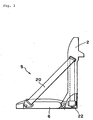
- Fig. 1 depicts a seat S that employs a cushioning member having a net-shaped skin according to the present invention and includes a seat back 2 and a seat cushion 6 rotatably connected to the seat back 2 via a hinge 4.
- each of the seat back 2 and the seat cushion 6 is the cushioning member having a net-shaped skin according to the present invention.
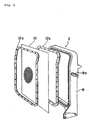
- the seat back 2 includes a seat back frame 8, a net-shaped skin 10 tensioned over the seat back frame 8, and a holding member 12 for holding the net-shaped skin 10 on the seat back frame 8.
- the seat back frame 8 has belt holes 8a, 8a (only one is shown in Fig. 2) defined therein on both sides thereof through which belts described later are drawn into the seat back frame 8.
- the seat cushion 6 includes a seat cushion frame 14, a net-shaped skin 16 tensioned over the seat cushion frame 14, and a holding member 18 for holding the net-shaped skin 16 on the seat cushion frame 14.
- the seat S also includes belts 20, 20 tensioned on both sides thereof, and each belt 20 has one end engaged with a belt anchor 22 rotatably mounted on the seat cushion frame 14 on one side thereof.
- the belt 20 is drawn to the inside of the seat back frame 8 through the belt hole 8a formed in the seat back frame 8.
- retractors 22, 22 are disposed inside the seat back frame 8 on both sides thereof in the vicinity of a lower end thereof, and the other ends of the belts 20, 20 are engaged with the retractors 22, 22, respectively.
- Figs. 1 and 3 depict the condition in which a man can sit on the seat with the belts 20, 20 completely drawn out of the retractors 22, 22, respectively.
- the seat is of a construction in which the load of a seat occupant applied to the seat back 2 is supported by the belts 20, 20.
- the belts 20, 20 are retracted into the retractors 22, 22 to fold the seat cushion 6 towards the seat back 2.
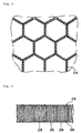
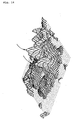
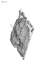
- Figs. 4 and 5 depict a three-dimensional mesh knit forming the net-shaped skins 10, 16.
- a fabric base is formed into a honeycomb-shaped (hexagonal) mesh.
- the mesh knit is of a three-layered solid truss structure in which an upper mesh layer 24 and a lower mesh layer 26 are connected to each other by a pile layer having a large number of piles 28.
- Each yarn of the upper mesh layer 24 and the lower mesh layer 26 is formed by twisting a number of fine threads, while each of the piles 28 is formed of a single thick string to provide the three-dimensional mesh knit with rigidity.
- Table 1 shows physical values of materials used for the upper mesh layer 24, the lower mesh layer 26, and the piles 28 forming the pile layer.
- Character d represents a denier
- 1d is a unit of thickness when 1 gram of thread has been pulled by 9,000 meters.
- Character f represents a filament that is a unit indicating the number of fine threads forming a yarn, and 60f means that a yarn is made of 60 fine threads.
- the pulling strength "kg/5cm” is a strength when a mesh having a width of 5 cm has been pulled in the longitudinal direction.
- straight in the pile texture means that hexagons of the upper mesh layer 24 and those of the lower mesh layer 26 completely overlap each other as viewed from above, while “cross” means that they deviate from each other.
- Thermoplastic resins are preferably used as the material of the three-dimensional mesh knit and it is sufficient if the material can be formed into fibers. When textiles are made of such material, it is sufficient if it provides a strength required for a sheet stock Typical examples are thermoplastic polyester resins such as polyethylene terephthalate (PET), polybutylene terephthalate (PBT), etc., polyamide resins such as nylon 6, nylon 66, etc., polyolefin resins such as polyethylene, polypropylene, etc., and resins in which more than two kinds of such resins are mixed.
- PET polyethylene terephthalate
- PBT polybutylene terephthalate
- polyamide resins such as nylon 6, nylon 66, etc.
- polyolefin resins such as polyethylene, polypropylene, etc.
- each pile 28 is greater than 380d and, preferably, greater than 600d so that the load of a seat occupant applied to the three-dimensional mesh knit can be supported by deformation of the hexagonal meshes and by inclination of the piles, thereby providing a soft structure that causes no stress concentration.
- the net-shaped skin 10 is placed between the seat back frame 8 and the holding member 12 and is joined thereto by vibration welding.
- the holding member 12 is not always required, and the seat back frame 8 and the net-shaped skin 10 can be directly joined together by vibration welding.
- the vibration welding makes use of frictional heat to fuse thermoplastic resins.
- the frictional heat is produced by pressing two parts to be welded to each other and by simultaneously imparting vibration of a several-millimeter width to the welding surface.
- the vibration is stopped after a lapse of two or three seconds, the two parts automatically return to their original positions without any positional deviations, and subsequent about 1-second cooling results in high-strength welding.
- the vibration welding has the advantages of short cycle, low power consumption and no smell, and is applicable to complicated or irregular configurations. In addition, the positioning between parts is possible and the welding of a number of parts at one time is also easily possible. Moreover, the vibration welding enables welding of different materials and is also characterized by high-strength welding irrespective of water absorption properties and hardness.
- the vibration welding is generally utilized to join plate-like members together, but is utilized, in the practice of the present invention, to join by fusing fibers into a plate-like member.
- the seat back frame 8 is made of a metal such as iron.
- the net-shaped skin 10 is placed between the holding members 12a, 12b and joined thereto by vibration welding, and is subsequently screwed to the metal seat back frame 8.
- the use of the metal seat back frame 8 increases the rigidity of the seat back, which is therefore applicable to an automotive seat or the like to which an impact load is applied. If the net-shaped skin 10 becomes unusable, it is advantageous in that the holding members 12a, 12b and the net-shaped skin 10 can be replaced together
- the net-shaped skin 10 after the net-shaped skin 10 has been joined to any one of the holding members 12a, 12b by vibration welding, it can be screwed to the metal seat back frame 8. In this case, of the holding members 12a, 12b, the one to which the net-shaped skin 10 has not been joined can be removed.
- Figs. 7 to 9 depict the second joining method.
- an edge treatment is carded out by passing a string (or a thread) 30 through edge portions of the upper mesh layer 24 and the lower mesh layer 26 of the net-shaped skin 10 at predetermined intervals to fix the net-shaped skin 10 to the holding member 12.
- the holding member 12 is secured to the seat back frame 8 by means of bolts 32 and nuts 34. Head portions of the bolts 32 are covered with, for example, a resinous cover 36.
- the string 30 is not always passed through both the upper mesh layer 24 and the lower mesh layer 26, and may be passed through only one of them.
- Figs. 10 and 11 depict the third joining method.
- a resinous frame 12c is first formed along the circumference of the net-shaped skin 10 by insert molding, and is subsequently secured to the seat back frame by means of screws 38.
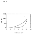
- Fig. 12 depicts a load-deflection curve of a three-dimensional mesh knit employed in the net-shaped skins 10, 16.
- This curve is a curve obtained by cutting off the three-dimensional mesh knit so as to have a circumferential length of 653 mm and by pressing a ⁇ 76-plate against it.
- This curve is a smooth non-linear curve compared with a curve of elastic material such as urethane. Because the three-dimensional mesh knit has a large hysteresis, when it is employed in an automotive seat, it can absorb external vibration energy effectively.
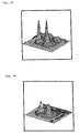
- Figs. 13 to 16 show body pressure distributions when a subject has sat on a conventional seat cushion and on a seat cushion employing a cushioning member according to the present invention.
- Figs. 13 and 14 show the body pressure distributions when a subject weighing 37 kg has sat on the conventional seat cushion and on the seat cushion employing the cushioning member according to the present invention, respectively, while
- Figs. 15 and 16 show the body pressure distributions when a subject weighing 93 kg has sat on the conventional seat cushion and on the seat cushion employing the cushioning member according to the present invention.
- urethane pads are partially fitted to a warn- and weft-knitted fabric in the form of a belt at positions where a feeling of foreign substances is sensed or the support pressure changes.
- the cushioning member of the present invention employing the three-dimensional mesh knit as the net-shaped skin includes the honeycomb-shaped upper and lower mesh layers 24, 26 and a large number of piles 28 each made of a single thick string, and is of a truss structure, it has the following advantages.
- the cushioning member having the net-shaped skin according to the present invention has the above-described features, when it is employed in, for example, a seat, it prevents hematogeous troubles around femoral regions, neuropathy, lumber troubles, etc., optimizes sweating or skin temperatures, and protects muscular tissues.
- the cushioning member having the net-shaped skin according to the present invention is employed in both the seat cushion and the seat back, it may be employed in only one of them. Also, the cushioning member of the present invention can be employed in a head rest mounted on the seat back, a bed, or the like.
- the cushioning member of the present invention is soft to sit on and has a soft spring constant in a region to be normally used, it does not easily transmit vibration even if it is thin and has a high rigidity. Accordingly, the cushioning member of the present invention can be employed in an automotive seat and also in a seat for a motorcycle because it is of the all-weather type.
- Fig. 17 schematically depicts several fabric base textures used for the upper and lower mesh layers 24, 26, (a) depicting a honeycomb-shaped (hexagonal) mesh shown in Fig. 4, (b) depicting a diamond-shaped mesh, and (c) depicting a chain-inserted texture.
- Fig. 18 schematically depicts pile textures connecting the upper and lower mesh layers 24, 26, (a) depicting a generally straight texture corresponding to Fig. 5, (b) depicting a generally straight texture in the form of a figure "8", (c) depicting a cross texture, and (d) depicting a cross texture in the form of a figure "8".
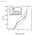
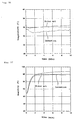
- Figs. 19 and 20 are graphs each showing static characteristics when a disc ( ⁇ 200) has been pressed against the cushioning member having the net-shaped skin according to the present invention.
- the fabric base texture of the honeycomb-shaped mesh shown in Fig. 17(a) is employed in the upper mesh layer 24, while the fabric base texture of the chain-inserted texture shown in Fig. 17(c) is employed in the lower mesh layer 26.
- the pile texture includes the generally straight texture of Fig. 18(a) as viewed in one direction and the cross texture of Fig. 18(c) as viewed in a direction perpendicular to said one direction. Items 09002D and D90028-5 (details thereof are described later) are used for the net-shaped skin.
- k3>k1>k2 where k1 is a spring constant in a small-load region, k2 a spring constant in a normal use region around a balanced point, and k3 a spring constant in a large-load region.
- the spring constant in the normal use region can be set to the smallest one.
- Table 2 shows physical values of the material used for the upper mesh layer 24, the lower mesh layer 26 and the piles 28 forming the pile layer, and those of other various materials.
- Fig. 21 shows static characteristics when the net-shaped skin showing the static characteristics of Fig. 19 and the net-shaped skin showing the static characteristics of Fig. 20.have been laminated.
- the lamination reduces the spring constant as a whole and, hence, the spring constant can be freely controlled by increasing the number of lamination. Also, the stroke to a bottom end increases, and the load applied to each of the piles reduces, thereby reducing the bottom-end shock
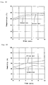
- Graphs shown in Figs. 22 to 24 schematize a relationship among load-deflection characteristics, transient response characteristics, and frequency response characteristics.
- the transient response and the frequency response of a non-linear spring system of Figs. 23 and 24 are improved as compared with those of a linear spring system of Fig. 22.
- the acceleration and deflection are attenuated quickly with respect to input changes and the period of time to the steady state is shod. This tendency becomes conspicuous with a reduction in spring constant around the balanced point.
- the spring constant is zero, resonant points disappear completely and attenuation starts.
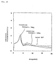
- Fig. 25 is a graph showing dynamic characteristics when a random wave has been inputted to a seat having a net-shaped skin according to the present invention and to a conventional seat employing urethane (thickness: 50 mm). There are little differences as a whole in the dynamic characteristics.
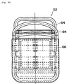
- Fig. 26 depicts a net-shaped skin into which rigid members 40 such as wires have been so inserted as to form a rectangle to enhance the spring action. Removal of the rigid members 40 is prevented by welding the piles positioned on both sides of each rigid member 40.
- Fig. 27 is a graph showing static characteristics when a disc ( ⁇ 200) has been pressed against a net-shaped skin of item 09001D shown in Table 2, while Figs. 28 and 29 are graphs showing static characteristics when wires ( ⁇ 6) have been inserted as the rigid members 40.
- the terms “Large” and “Small” mean the interval between the wires to be inserted, as shown in Fig. 26(a).
- the spring constant becomes large as a whole, and an increased surface rigidity increases the region resistant to load and reduces the bottom-end shock. If elastic members are used in place of the rigid members, the elasticity thereof can be utilized.
- Fig. 30 depicts a cushioning member having a net-shaped skin to which resinous elastic members 42 such as PBT (polybutylene terephthalate) have been vibration-welded at two positions at a predetermined interval.
- Fig. 31 is a graph showing static characteristics when a disc ( ⁇ 200) has been pressed against such a cushioning member.
- the vibration welding of the resinous members increases the spring constant in the normal use region, enlarges the range of the normal use region, and reduces the bottom-end shock, as in the case in which the rigid members have been inserted in the form of a rectangle.
- Fig. 32 depicts a seat S1 in which the net-shaped skin according to the present invention is employed in a seat cushion 44 and in a seat back 46.
- the net-shaped skin 48 is vibration-welded at its periphery to elastic members 50, and the periphery of the net-shaped skin 48 and the elastic members 50 are both joined to a patch or trim 52 by sewing.
- the trim 52 is further joined to a side skin 54 by sewing.
- Resins such as polypropylene or the like, wadding (hard pads), fabric bases, etc. are preferably used for the elastic members 50.
- the net-shaped skin 48 is joined at its periphery to the engageable members 56 by vibration welding for the fixing thereof to a portion 58 of a frame.
- vibration welding for the fixing thereof to a portion 58 of a frame.
- the engageable members 56 may be engaged with a fitting 62 of the frame.
- rigid members 50 vibration-welded to the periphery of the net-shaped skin may be first inserted into the fitting 62, which can be in turn secured to the frame, as shown in Fig. 36, thereby imparting a desired tension to the net-shaped skin without using any tensioning jig.
- the engageable members 56 may be sewn and vibration-welded to only the lower mesh layer 26 of the net-shaped skin and, under the condition in which only sewn portions of the pile layer 28 that connects the upper and lower mesh layers 24, 26 are compressed, the periphery of the net-shaped skin may be joined to one end of a side skin 60 by sewing.
- the other end of the side skin 60 is sewn and vibration-welded to the rigid members 50, which are in turn engaged with the fitting 62 of the frame together with the engageable members 56.
- the lower mesh layer 26 and the engageable members 56 may be joined together by extrusion-molding or injection-molding the engageable members 56 to end portions of the lower mesh layer 26.
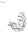
- a seat in which a plurality of net-shaped skins according to the present invention are laminated is discussed hereinafter with reference to Figs. 40 to 43.
- a seat S2 shown in Figs. 40 to 42 includes a seat cushion 66 having a plurality of net-shaped skins laminated on pipe frames 64 and a seat back 68 similarly having a plurality of laminated net-shaped skins.
- each of the seat cushion 66 and the seat back 68 employs the plurality of net-shaped skins as the first layer 70, the second layer 72, the third layer 74, the fourth layer 76, the fifth layer 78, and the sixth layer 80, all of which are laminated one above the other in this order.
- the rigid members 40 as shown in Fig. 26 are inserted into the net-shaped skin 80 of the sixth layer.
- Any one of the second to sixth layers 72-80 may be an urethane layer.
- a thin urethane layer causes a bottom-end shock and, hence, a spring structure is normally imparted thereto or a highly elastic urethane is combined therewith.
- a structure makes a cushion thick as a whole, a combination of the nets and urethane makes the cushion thinner than the conventional one and can cope with the bottom-end shock.
- a plurality of (five in Fig. 42) rolled net-shaped skins 82 may be arranged in a side-by-side fashion in place of the second to fifth layers 72-78 shown in Fig. 43.
- the structure in which the plurality of net-shaped skins are laminated as shown in Fig. 43 or in which the rolled net-shaped skins are juxtaposed as shown in Fig. 44 can reduce the bottom-end shock that is received by a user on a seat and reduces a spring constant to thereby improve the vibration characteristics around the resonant points. It is possible to further improve the vibration characteristics around the resonant points by incorporating a different kind of material such as a damping material, viscoelastic urethane, highly elastic urethane, low-repulsive urethane or the like. It is also possible to make a seat comfortable or soft to sit on and have a relatively large stroke, thereby enhancing an initial feeling.
- Figs. 45 and 46 show the body pressure distributions (subject weight: 50 kg) when no wires have been inserted into the honeycomb-shaped upper and lower mesh layers 24, 26 and when wires have been inserted as shown in Fig. 26 (wire interval: large), respectively.
- Figs. 47 and 48 similarly show the body pressure distributions (subject weight 50 kg) when no wires have been inserted into the honeycomb-shaped upper and lower mesh layers 24, 26 and when wires have been inserted as shown in Fig. 26 (wire interval: small), respectively.
- the surface rigidity of the cushioning member having the net-shaped skin is increased by inserting the wires, and the increased surface rigidity disperses the body pressure to thereby reduce the local pressure.
- Figs. 49 and 50 show body pressure distributions (subject weight: 50 kg) when the subject has sat on a laminated structure of the net-shaped skin showing the static characteristics of Fig. 19 and the net-shaped skin showing the static characteristics of Fig. 20 with no resinous members vibration-welded thereto and when the subject has sat on another laminated structure in which the resinous members have been vibration-welded thereto (only the lower layer), as shown in Fig. 30, respectively.
- the vibration welding of the resinous members makes each pile forming the pile layer resistant to deflection, which disperses the body pressure, thereby reducing the local pressure.
- the elasticity of the cushioning member can be improved as a whole by making use of the elasticity of the resinous members, contributing to a reduction of the bottom-end shock.
- Figs. 51 and 52 show body pressure distributions (subject weight: 50 kg) when the subject has sat on a conventional seat employing urethane as a cushioning material and when he has sat on a wheelchair employing the laminated structure shown in Fig. 43, respectively.
- the laminated structure of the cushioning member according to the present invention effectively disperses the body pressure and reduces the local pressure.
- Figs. 53 and 54 show body pressure distributions (subject weight: 74 kg) when another subject has sat on a conventional wheelchair and when he has sat on the wheelchair employing the laminated structure shown in Fig. 43, respectively.
- the laminated structure of the cushioning member according to the present invention effectively disperses the body pressure and reduces the local pressure irrespective of the subject weight.
- Temperature and humidity characteristics are discussed hereinafter when a subject has sat on the conventional wheelchair and when he sat on the wheelchair having the laminated structure of the cushioning member according to the present invention.
- Fig. 55 shows several check points where temperature and humidity characteristics have been examined.
- Figs. 56 and 57 show the characteristics at point Cushion-A when the subject is a great sweater
- Figs. 58 and 59 show the characteristics at point Back-A when the subject is an average man (not a great sweater).
- the temperature and humidity of the atmosphere were 35°C and 65%, respectively.
- the wheelchair according to the present invention is excellent in air permeability and heat dissipation properties, the temperature characteristics and the humidity characteristics are both improved as compared with the conventional wheelchair.
- the present invention provides the following effects.
- a cushioning member according to the present invention includes a net-shaped skin tensioned over a frame, the air permeability is enhanced, and a seat or bed can be reduced in weight by incorporating the cushioning member thereinto. Also, because the net-shaped skin is of a three-layered structure including an upper mesh layer, a lower mesh layer, and a pile layer having a large number of piles that connect the upper and lower mesh layers, and because each of the piles is made of a single string, the cushioning member has desired cushioning characteristics by the action of the elasticity of each pile.
- both the frame and the net-shaped skin are both made of a thermoplastic resin and joined together by vibration welding, they can be easily and strongly joined within a short period of time without lowering the physical properties of threads or strings of the net-shaped skin. Also, because both the frame and the net-shaped skin are made of a thermoplastic resin, it is possible to make all-weather seats that can be employed in motorcycles exposed to rainwater or the like.
- the holding member can be secured to a metal frame, which can be incorporated into an automotive seat that may receive an impact load. If the net-shaped skin is damaged, the skin and the holding member can be replaced together.
- an optional material can be used for the holding member or the frame.
- a resinous frame member is formed at the periphery of the net-shaped skin by insert molding and is secured to the above frame, a metal frame can be employed which can be incorporated into an automotive seat. In this case, if the net-shaped skin is damaged, the skin and the resinous frame member can be replaced together.
- the pile layer has a cross texture as viewed in a specific direction, there is no directional property of inclination of piles, enhancing the rigidity and allowing the sewing.
- the net-shaped skin has non-linear static load-deflection characteristics and also has the smallest spring constant in a normal use region including a balanced point, the transient response characteristics and the frequency response characteristics can be both improved. That is, the acceleration and deflection are attenuated quickly with respect to input changes and, hence, the period of time to the steady state can be shortened.
- the surface rigidity or the entire rigidity of the net-shaped skin can be increased, thereby reducing a bottom-end shock.
- the engageable members when the engageable members are attached at the periphery of the lower mesh layer and engaged with a portion of a seat under the condition in which the pile layer other than the sewn portions is not compressed, no feeling of foreign substances is sensed at the periphery of the net-shaped skin.
- the engageable members can be readily attached at the periphery of the lower mesh layer by extrusion-molding or injection-molding.
- the seat can be made thin, reduces a bottom-end shock, and improves vibration characteristics around the balanced point, as compared with conventional structures.
Abstract
Description
- The present invention relates to a cushioning member having a net-shaped skin that has excellent air permeability and can be employed in a seat, bed or the like, and also relates to a seat employing such a cushioning member.
- Conventional automotive seats generally include spring members such as coil springs, S-shaped springs, or formed wire springs mounted on a seat frame, a pad material such as a foamed material, rocking material, or cotton placed thereon, and a skin such as a vinyl leather, woven cloth, or leather covered thereon.
- In order to enhance the elasticity or shock-absorbing properties, those in which a viscoelastic material is embedded in the pad material have been proposed.
- Furthermore, when a user keeps sitting on a seat for many hours, those portions of the user that are held in contact with a seat cushion and a seat back become moist with sweat and, hence, an unpleasant feeling increases. To overcome this problem, seats having enhanced air permeability by forcibly feeding air from the inside of the seat cushion and the seat back have also been proposed.
- On the other hand, seats or beds other than the automotive seats generally include a pad material placed on the frame and covered with a skin, and some of them also include spring members for enhancing the cushioning characteristics.
- Although the spring members or the pad material acts to provide desired cushioning characteristics, some of the conventional seats or beds referred to above cannot eliminate a bottom-end shock, and such seats or beds are mostly heavy and costly.
- In motorcycles having a viscoelastic material embedded in the pad material, if gasoline that has leaked out during refueling or water such as rainwater is splashed thereon and is brought into contact with the viscoelastic material, it sometimes changes the nature thereof. In the automotive seats, there is a possibility of fogging in which volatile components contained in the viscoelastic material fog window panes.
- Although the seats in which air is forcibly fed from the inside of the seat cushion and the seat back have excellent air permeability, they are costly because they require a device for forcibly feeding air or an air passage formed in the pad material.
- The present invention has been developed to overcome the above-described disadvantages. It is accordingly an objective of the present invention to provide a relatively light all-weather cushioning member or seat having a net-shaped skin that has excellent air permeability and heat dissipating characteristics while maintaining desired cushioning characteristics and eliminating a bottom-end shock. Disclosure of the Invention
- In accomplishing the above objectives, a cushioning member having a net-shaped skin according to the present invention comprises a frame and a net-shaped skin tensioned over the frame, said net-shaped skin comprising an upper mesh layer, a lower mesh layer, and a pile layer having a large number of piles that connect the upper and lower mesh layers, each of the piles being made of a single string.
- It is preferred that each of the frame and the net-shaped skin is made of a thermoplastic resin, and both of them are joined together by vibration welding.
- Alternatively, the frame is made of a metal, while the net-shaped skin is made of a thermoplastic resin, wherein after the net-shaped skin has been joined to at least one holding member made of a thermoplastic resin, the holding member is secured to the frame.
- Again alternatively, after the net-shaped skin has been secured at a periphery thereof to a holding member by a string, the holding member is secured to the frame.
- It is also possible to form a resinous frame at a periphery of the net-shaped skin by insert molding and to secure the resinous frame to the frame.
- A seat having a net-shaped skin according to the present invention is characterized in that at least one of a seat cushion, a seat back, and a head rest includes a frame and a net-shaped skin tensioned over the frame, wherein the net-shaped skin includes an upper mesh layer, a lower mesh layer, and a pile layer having a large number of piles that connect the upper and lower mesh layers, each of the piles being made of a single string.
- Furthermore, a cushioning member having a net-shaped skin according to the present invention is characterized in that the net-shaped skin is of a three-layered structure including an upper mesh layer, a lower mesh layer, and a pile layer having a large number of piles that connect the upper and lower mesh layers, each of the piles being made of a single string, the pile layer presenting a cross texture as viewed in a predetermined direction.
- This cushioning member has non-linear static load-deflection characteristics and also has at least three spring constants in a normal use region, a region smaller in load than the normal use region, and a region greater in load than the normal use region, wherein the spring constant in the normal use region is set to the smallest one.
- Preferably, rigid members or elastic members are disposed at predetermined intervals in at least one direction, thereby increasing a surface rigidity or elasticity of the upper mesh layer.
- Also, engageable members may be mounted on a periphery of the net-shaped skin by sewing and vibration welding, wherein the engageable members are mounted on a portion of a seat.
- Alternatively, the engageable members are mounted on a periphery of the lower mesh layer, wherein the engageable members are mounted on a portion of a seat under the condition in which the pile layer is not compressed.
- The engageable members may be mounted on the periphery of the lower mesh layer by extrusion molding.
- A seat according to the present invention is also characterized by a plurality of net-shaped skins laminated one upon another, wherein each of the net-shaped skins is of a three-layered structure including an upper mesh layer, a lower mesh layer, and a pile layer having a large number of piles that connect the upper and lower mesh layers, each of the piles being made of a single string, the pile layer presenting a cross texture as viewed in a predetermined direction.
- A plurality of rolled net-shaped skins may be arranged in a side-by-side fashion in place of the plurality of laminated net-shaped skins.
-
- Fig. 1 is a perspective view of a seat provided with a cushioning member having a net-shaped skin according to the present invention.
- Fig. 2 is an exploded perspective view of a seat back constituting the seat of Fig. 1.
- Fig. 3 is a side view, partly in section, of the seat of Fig. 1.
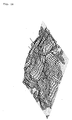
- Fig. 4 is a fragmentary front view, on an enlarged scale, of the net-shaped skin.
- Fig. 5 is a fragmentary side view of the net-shaped skin.
- Fig. 6 is an exploded perspective view of a modified form of the seat back.
- Fig. 7 is a fragmentary perspective view depicting how to join the net-shaped skin to a holding member.
- Fig. 8 is a fragmentary front view of the net-shaped skin and the holding member of Fig. 7 after joining.
- Fig. 9 is a fragmentary sectional view of the seat back when the net-shaped skin and the holding member have been secured to a frame.
- Fig. 10 is a perspective view of the net-shaped skin and the holding member joined together by another joining method.
- Fig. 11 is a fragmentary sectional view of the seat back when the net-shaped skin and the holding member of Fig. 10 is secured to the frame.
- Fig. 12 is a graph showing a load-deflection curve of a three-dimensional mesh knit employed in the net-shaped skin.
- Fig. 13 is a graph showing a body pressure distribution when a subject weighing 37kg has sat on a conventional seat cushion.
- Fig. 14 is a graph showing a body pressure distribution when the subject weighing 37kg has sat on the seat cushion according to the present invention.
- Fig. 15 is a graph showing a body pressure distribution when a subject weighing 93kg has sat on the conventional seat cushion.
- Fig. 16 is a graph showing a body pressure distribution when the subject weighing 93kg has sat on the seat cushion according to the present invention.
- Fig. 17 schematically depicts several fabric base textures used for upper and lower mesh layers, (a) depicting a honeycomb-shaped (hexagonal) mesh shown in Fig. 4, (b) depicting a diamond-shaped mesh, and (c) depicting a chain-inserted texture.
- Fig. 18 schematically depicts pile textures connecting the upper and lower mesh layers, (a) depicting a generally straight texture corresponding to Fig. 5, (b) depicting a generally straight texture in the form of a figure "8", (c) depicting a cross texture, and (d) depicting a cross texture in the form of a figure "8".
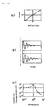
- Fig. 19 is a graph showing static characteristics when a disc has been pressed against a cushioning member according to the present invention.
- Fig. 20 is a graph showing static characteristics when the disc has been pressed against another cushioning member according to the present invention.
- Fig. 21 is a graph showing static characteristics of a laminated structure that has the cushioning member showing the static characteristics of Fig. 19 and the cushioning member showing the static characteristics of Fig. 20.
- Fig. 22 depicts several characteristics of a linear spring system, (a) depicting load-deflection characteristics, (b) depicting transient response characteristics, and (c) depicting frequency response characteristics.
- Fig. 23 depicts several characteristics of a non-linear spring system, (a) depicting load-deflection characteristics, (b) depicting transient response characteristics, and (c) depicting frequency response characteristics.
- Fig. 24 depicts several characteristics of another non-linear spring system, (a) depicting load-deflection characteristics, (b) depicting transient response characteristics, and (c) depicting frequency response characteristics.
- Fig. 25 is a graph showing dynamic characteristics when a random wave has been inputted to a seat having a net-shaped skin according to the present invention and to a conventional seat employing urethane.
- Fig. 26 depicts a net-shaped skin into which rigid members such as wires have been so inserted as to form a rectangle, (a) being a schematic perspective view thereof, and (b) being a schematic vertical sectional view thereof.
- Fig. 27 is a graph showing static characteristics when a disc has been
pressed against a net-shaped skin of
item 09001D shown in Table 2. - Fig. 28 is a graph showing static characteristics when wires have been
inserted into the net-shaped skin of
item 09001D at large intervals. - Fig. 29 is a graph showing static characteristics when wires have been
inserted into the net-shaped skin of
item 09001D at small intervals. - Fig. 30 depicts a cushioning member having a net-shaped skin to which resinous members have been vibration-welded at predetermined intervals, (a) being a schematic perspective view thereof, and (b) being a schematic top plan view thereof.
- Fig. 31 is a graph showing static characteristics when a disc has been pressed against the cushioning member of Fig. 30.
- Fig. 32 is a perspective view of a seat employing the net-shaped skin according to the present invention.
- Fig. 33 is a cross-sectional view taken along line XXXIII-XXXIII in Fig. 32.
- Fig. 34 is a cross-sectional view of the net-shaped skin and a seat frame joined together.
- Fig. 35 is a cross-sectional view of the net-shaped skin and the seat frame joined together in a different fashion.
- Fig. 36 is a cross-sectional view of the net-shaped skin and the seat frame joined together in another different fashion.
- Fig. 37 is a fragmentary perspective view of a circumferential edge portion of the net-shaped skin when the pile layer has not been compressed.
- Fig. 38 is a cross-sectional view of the net-shaped skin of Fig. 37 and the seat frame joined together.
- Fig. 39 is a cross-sectional view of a net-shaped skin having a hook member secured thereto by extrusion-molding or injection-molding.
- Fig. 40 is a front view of a seat having a seat back in which a plurality of net-shaped skins have been laminated.
- Fig. 41 is a top plan view of the seat of Fig. 40, particularly depicting a seat cushion in which net-shaped skins have been laminated.
- Fig. 42 is a side view of the seat of Fig. 40, partly in section, in which a viscoelastic urethane has been incorporated together with the net-shaped skins.
- Fig. 43 is a cross-sectional view taken along line XLIII-XLIII in Fig. 42.
- Fig. 44 is a cross-sectional view taken along line XLIII-XLIII in Fig. 42 when a plurality of rolled net-shaped skins have been disposed in a side-by-side fashion.
- Fig. 45 is a graph showing a body pressure distribution when a subject has sat on a net-shaped skin having a honeycomb-shaped layer in which no wires have been inserted.
- Fig. 46 is a graph showing a body pressure distribution when the subject has sat on a net-shaped skin having a honeycomb-shaped layer in which wires have been inserted.
- Fig. 47 is a graph showing a body pressure distribution when the subject has sat on a relatively small net-shaped skin having a honeycomb-shaped layer in which no wires have been inserted.
- Fig. 48 is a graph showing a body pressure distribution when the subject has sat on a relatively small net-shaped skin having a honeycomb-shaped layer in which wires have been inserted.
- Fig. 49 is a graph showing a body pressure distribution when the subject has sat on a laminated structure of the net-shaped skin showing the static characteristics of Fig. 19 and the net-shaped skin showing the static characteristics of Fig. 20.
- Fig. 50 is a graph showing a body pressure distribution when the subject has sat on a laminated structure of the net-shaped skin showing the static characteristics of Fig. 19 and the net-shaped skin showing the static characteristics of Fig. 20, with resinous members being vibration-welded to a portion of the laminated structure..
- Fig. 51 is a graph showing a body pressure distribution when the subject has sat on a conventional seat employing urethane as a cushioning material.
- Fig. 52 is a graph showing a body pressure distribution when the subject has sat on a wheelchair employing the laminated structure shown in Fig. 43.
- Fig. 53 is a graph showing a body pressure distribution when another subject having a different weight has sat on a conventional wheelchair.
- Fig. 54 is a graph showing a body pressure distribution when the subject of Fig. 53 has sat on the wheelchair employing the laminated structure shown in Fig. 43.
- Fig. 55 is a schematic perspective view of a seat having several check points where temperature and humidity characteristics have been examined in a conventional wheelchair and a wheelchair according to the present invention.
- Fig. 56 is a graph showing temperature characteristics at point Cushion-A in Fig. 55 when the subject is a great sweater.
- Fig. 57 is a graph showing humidity characteristics at point Cushion-A in Fig. 55 when the subject is a great sweater.
- Fig. 58 is a graph showing temperature characteristics at point Back-A in Fig. 55 when the subject is an average man.
- Fig. 59 is a graph showing humidity characteristics at point Back-A in Fig. 55 when the subject is an average man.
-
- Embodiments of the present invention are discussed hereinafter with reference to the drawings.
- Fig. 1 depicts a seat S that employs a cushioning member having a net-shaped skin according to the present invention and includes a seat back 2 and a
seat cushion 6 rotatably connected to the seat back 2 via ahinge 4. - In the seat S of Fig. 1, each of the seat back 2 and the
seat cushion 6 is the cushioning member having a net-shaped skin according to the present invention. - As shown in Fig. 2, the seat back 2 includes a seat back
frame 8, a net-shapedskin 10 tensioned over the seat backframe 8, and a holdingmember 12 for holding the net-shapedskin 10 on the seat backframe 8. The seat backframe 8 hasbelt holes frame 8. - Like the seat back 2, the
seat cushion 6 includes aseat cushion frame 14, a net-shapedskin 16 tensioned over theseat cushion frame 14, and a holdingmember 18 for holding the net-shapedskin 16 on theseat cushion frame 14. - The seat S also includes
belts belt 20 has one end engaged with abelt anchor 22 rotatably mounted on theseat cushion frame 14 on one side thereof. Thebelt 20 is drawn to the inside of the seat backframe 8 through thebelt hole 8a formed in the seat backframe 8. - As shown in Fig. 3,
retractors frame 8 on both sides thereof in the vicinity of a lower end thereof, and the other ends of thebelts retractors belts retractors belts - When the seat is stored and the
seat cushion 6 is pushed up, thebelts retractors seat cushion 6 towards the seat back 2. - Figs. 4 and 5 depict a three-dimensional mesh knit forming the net-shaped
skins upper mesh layer 24 and alower mesh layer 26 are connected to each other by a pile layer having a large number ofpiles 28. - Each yarn of the
upper mesh layer 24 and thelower mesh layer 26 is formed by twisting a number of fine threads, while each of thepiles 28 is formed of a single thick string to provide the three-dimensional mesh knit with rigidity. - Table 1 shows physical values of materials used for the
upper mesh layer 24, thelower mesh layer 26, and thepiles 28 forming the pile layer.
- In Table 1, "*A" means that the material has been colored to black. Character d represents a denier, and 1d is a unit of thickness when 1 gram of thread has been pulled by 9,000 meters. 210d is a thickness when 1 gram of thread has been pulled by 9,000/210=42.9 meters. Character f represents a filament that is a unit indicating the number of fine threads forming a yarn, and 60f means that a yarn is made of 60 fine threads. The pulling strength "kg/5cm" is a strength when a mesh having a width of 5 cm has been pulled in the longitudinal direction. Furthermore, "straight" in the pile texture means that hexagons of the
upper mesh layer 24 and those of thelower mesh layer 26 completely overlap each other as viewed from above, while "cross" means that they deviate from each other. - Thermoplastic resins are preferably used as the material of the three-dimensional mesh knit and it is sufficient if the material can be formed into fibers. When textiles are made of such material, it is sufficient if it provides a strength required for a sheet stock Typical examples are thermoplastic polyester resins such as polyethylene terephthalate (PET), polybutylene terephthalate (PBT), etc., polyamide resins such as
nylon 6,nylon 66, etc., polyolefin resins such as polyethylene, polypropylene, etc., and resins in which more than two kinds of such resins are mixed. - The fiber thickness of each
pile 28 is greater than 380d and, preferably, greater than 600d so that the load of a seat occupant applied to the three-dimensional mesh knit can be supported by deformation of the hexagonal meshes and by inclination of the piles, thereby providing a soft structure that causes no stress concentration. - Methods in which the seat back
frame 8 and the net-shaped skin both constituting the seat back 2 are joined are explained hereinafter. - In the first method, after both the seat back
frame 8 and the holdingmember 12 have been made of a thermoplastic resin, the net-shapedskin 10 is placed between the seat backframe 8 and the holdingmember 12 and is joined thereto by vibration welding. - However, the holding
member 12 is not always required, and the seat backframe 8 and the net-shapedskin 10 can be directly joined together by vibration welding. - The vibration welding makes use of frictional heat to fuse thermoplastic resins. The frictional heat is produced by pressing two parts to be welded to each other and by simultaneously imparting vibration of a several-millimeter width to the welding surface. In general, when the vibration is stopped after a lapse of two or three seconds, the two parts automatically return to their original positions without any positional deviations, and subsequent about 1-second cooling results in high-strength welding.
- The vibration welding has the advantages of short cycle, low power consumption and no smell, and is applicable to complicated or irregular configurations. In addition, the positioning between parts is possible and the welding of a number of parts at one time is also easily possible. Moreover, the vibration welding enables welding of different materials and is also characterized by high-strength welding irrespective of water absorption properties and hardness.
- The vibration welding is generally utilized to join plate-like members together, but is utilized, in the practice of the present invention, to join by fusing fibers into a plate-like member.
- In Fig. 6, while a pair of holding
members 12a, 12b are made of a thermoplastic resin, the seat backframe 8 is made of a metal such as iron. The net-shapedskin 10 is placed between the holdingmembers 12a, 12b and joined thereto by vibration welding, and is subsequently screwed to the metal seat backframe 8. - The use of the metal seat back
frame 8 increases the rigidity of the seat back, which is therefore applicable to an automotive seat or the like to which an impact load is applied. If the net-shapedskin 10 becomes unusable, it is advantageous in that the holdingmembers 12a, 12b and the net-shapedskin 10 can be replaced together - It is to be noted that after the net-shaped
skin 10 has been joined to any one of the holdingmembers 12a, 12b by vibration welding, it can be screwed to the metal seat backframe 8. In this case, of the holdingmembers 12a, 12b, the one to which the net-shapedskin 10 has not been joined can be removed. - Figs. 7 to 9 depict the second joining method.
- As shown in Figs. 7 and 8, an edge treatment is carded out by passing a string (or a thread) 30 through edge portions of the
upper mesh layer 24 and thelower mesh layer 26 of the net-shapedskin 10 at predetermined intervals to fix the net-shapedskin 10 to the holdingmember 12. Thereafter, as shown in Fig. 9, the holdingmember 12 is secured to the seat backframe 8 by means ofbolts 32 and nuts 34. Head portions of thebolts 32 are covered with, for example, aresinous cover 36. - It is to be noted that the
string 30 is not always passed through both theupper mesh layer 24 and thelower mesh layer 26, and may be passed through only one of them. - Figs. 10 and 11 depict the third joining method.
- According to this method, a
resinous frame 12c is first formed along the circumference of the net-shapedskin 10 by insert molding, and is subsequently secured to the seat back frame by means ofscrews 38. - Because the joining method for parts of the
seat cushion 6 is the same as the joining method for the seat back 2 referred to above, description thereof is omitted. - Fig. 12 depicts a load-deflection curve of a three-dimensional mesh knit employed in the net-shaped
skins - This curve is a curve obtained by cutting off the three-dimensional mesh knit so as to have a circumferential length of 653 mm and by pressing a 76-plate against it. This curve is a smooth non-linear curve compared with a curve of elastic material such as urethane. Because the three-dimensional mesh knit has a large hysteresis, when it is employed in an automotive seat, it can absorb external vibration energy effectively.
- Figs. 13 to 16 show body pressure distributions when a subject has sat on a conventional seat cushion and on a seat cushion employing a cushioning member according to the present invention. Figs. 13 and 14 show the body pressure distributions when a subject weighing 37 kg has sat on the conventional seat cushion and on the seat cushion employing the cushioning member according to the present invention, respectively, while Figs. 15 and 16 show the body pressure distributions when a subject weighing 93 kg has sat on the conventional seat cushion and on the seat cushion employing the cushioning member according to the present invention.
- In the conventional seat cushion, urethane pads are partially fitted to a warn- and weft-knitted fabric in the form of a belt at positions where a feeling of foreign substances is sensed or the support pressure changes.
- As shown in Figs. 13 and 14, when the subject weighing 37 kg has sat on the seat cushions, peak values (arrows) of a load applied to the seat cushion employing the cushioning member of the present invention were considerably reduced as compared with peak values (arrows) of a load applied to the conventional seat cushion. Actual measurements revealed that the peak values were reduced by nearly about one third.
- As shown in Figs. 15 and 16, when the subject weighing 93 kg has sat on the seat cushions, peak values (arrows) of a load applied to the seat cushion employing the cushioning member of the present invention were also considerably reduced as compared with peak values (arrows) of a load applied to the conventional seat cushion. Actual measurements revealed that the peak values were reduced by nearly about one third.
- Furthermore, because the cushioning member of the present invention employing the three-dimensional mesh knit as the net-shaped skin includes the honeycomb-shaped upper and lower mesh layers 24, 26 and a large number of
piles 28 each made of a single thick string, and is of a truss structure, it has the following advantages. - (1) Because each pile is elastic, the hardness, elasticity or fitness can be controlled by changing the quality of the material, fiber thickness, texture or physical characteristics thereof.
- (2) By making use of the shape memory function of the honeycomb shape, the restoring capability and the resistance to deformation can be both enhanced.
- (3) The truss structure makes it possible to provide a thin and hard-to-deform elastic structure having good pressure dispersing and moderating capabilities and improved fitness.
- (4) Because the cushioning member is of a uniform honeycomb-shaped truss structure in which each part is independent, it is excellent in body pressure dispersion (low and uniform body pressure distribution) and can accommodate physical differences. For thin and fleshless men, the cushioning member can prevent a frontward slip by concentrating, at low pressures, the body pressure on the tuber ischiadicum that is relatively insensitive to fatigue. Also, the cushioning member is excellent in weight movement and easy to change the attitude, and reduces the frictional shear force.
- (5) The honeycomb-shaped truss structure does not bring about the state similar to a hammock (the state in which pressures are locally concentrated and strong side pressures are received), enables a user to take a natural attitude, and reduces a feeling of foreign substances by the effect of the elastic honeycomb structure.
- (6) The honeycomb-shaped truss structure provides a porous structure that is excellent in permeability to air and permeability to water vapor.
- (7) The honeycomb-shaped truss structure enlarges the support (contact) area. Although the user is supported over the whole support area, he is locally supported by each of the yarns forming the honeycomb shape. Accordingly, the honeycomb-shaped structure does not become stuffy.
- (8) Without an outermost layer of the skin and without any pads, a feeling of foreign substances is reduced by the framed thin and highly elastic member.
- (9) The honeycomb-shaped truss structure increases the strength.
-
- Because the cushioning member having the net-shaped skin according to the present invention has the above-described features, when it is employed in, for example, a seat, it prevents hematogeous troubles around femoral regions, neuropathy, lumber troubles, etc., optimizes sweating or skin temperatures, and protects muscular tissues.
- Although in the above-described embodiment the cushioning member having the net-shaped skin according to the present invention is employed in both the seat cushion and the seat back, it may be employed in only one of them. Also, the cushioning member of the present invention can be employed in a head rest mounted on the seat back, a bed, or the like.
- Furthermore, because the cushioning member of the present invention is soft to sit on and has a soft spring constant in a region to be normally used, it does not easily transmit vibration even if it is thin and has a high rigidity. Accordingly, the cushioning member of the present invention can be employed in an automotive seat and also in a seat for a motorcycle because it is of the all-weather type.
- Because the cushioning member of the present invention includes various modifications, they are explained hereinafter.
- Fig. 17 schematically depicts several fabric base textures used for the upper and lower mesh layers 24, 26, (a) depicting a honeycomb-shaped (hexagonal) mesh shown in Fig. 4, (b) depicting a diamond-shaped mesh, and (c) depicting a chain-inserted texture.
- Fig. 18 schematically depicts pile textures connecting the upper and lower mesh layers 24, 26, (a) depicting a generally straight texture corresponding to Fig. 5, (b) depicting a generally straight texture in the form of a figure "8", (c) depicting a cross texture, and (d) depicting a cross texture in the form of a figure "8".
- Figs. 19 and 20 are graphs each showing static characteristics when a disc ( 200) has been pressed against the cushioning member having the net-shaped skin according to the present invention. The fabric base texture of the honeycomb-shaped mesh shown in Fig. 17(a) is employed in the
upper mesh layer 24, while the fabric base texture of the chain-inserted texture shown in Fig. 17(c) is employed in thelower mesh layer 26. The pile texture includes the generally straight texture of Fig. 18(a) as viewed in one direction and the cross texture of Fig. 18(c) as viewed in a direction perpendicular to said one direction.Items 09002D and D90028-5 (details thereof are described later) are used for the net-shaped skin. - As can be seen from the graphs of Figs. 19 and 20, the following relationship is established:
- In the above-described formula, when the load applied to the net-shaped skin is small, deformation of the fabric base texture of the
upper mesh layer 24 has a great influence on the static characteristics, and the upper mesh layer greatly contributes to the spring constant k1. In the normal use region or the large-load region, upon deformation of theupper mesh layer 24, deformation of the pile layer greatly contributes to the spring constants k2 and k3. In particular, the cross texture formed in the pile texture in the specific direction provides a rigidity sufficient to secure a space between the upper and lower mesh layers when a predetermined load is applied thereto. - Table 2 shows physical values of the material used for the
upper mesh layer 24, thelower mesh layer 26 and thepiles 28 forming the pile layer, and those of other various materials.
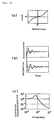
- Fig. 21 shows static characteristics when the net-shaped skin showing the static characteristics of Fig. 19 and the net-shaped skin showing the static characteristics of Fig. 20.have been laminated. The lamination reduces the spring constant as a whole and, hence, the spring constant can be freely controlled by increasing the number of lamination. Also, the stroke to a bottom end increases, and the load applied to each of the piles reduces, thereby reducing the bottom-end shock
- Graphs shown in Figs. 22 to 24 schematize a relationship among load-deflection characteristics, transient response characteristics, and frequency response characteristics. The transient response and the frequency response of a non-linear spring system of Figs. 23 and 24 are improved as compared with those of a linear spring system of Fig. 22.
- More specifically, in the non-linear spring system having a smaller spring constant around the balanced point than that of the linear spring system, the acceleration and deflection are attenuated quickly with respect to input changes and the period of time to the steady state is shod. This tendency becomes conspicuous with a reduction in spring constant around the balanced point. Because the resonant frequency is given by:
f - Fig. 25 is a graph showing dynamic characteristics when a random wave has been inputted to a seat having a net-shaped skin according to the present invention and to a conventional seat employing urethane (thickness: 50 mm). There are little differences as a whole in the dynamic characteristics.
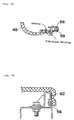
- Fig. 26 depicts a net-shaped skin into which
rigid members 40 such as wires have been so inserted as to form a rectangle to enhance the spring action. Removal of therigid members 40 is prevented by welding the piles positioned on both sides of eachrigid member 40. - As shown in Fig. 26(b), when a load m is applied to the net-shaped skin, axial components thereof act on X-piles (piles crossing each other), while horizontal components thereof act on the
upper mesh layer 24. The horizontal components acting on theupper mesh layer 24 are affected by an increased surface rigidity of the net-shaped skin, resulting in a reduction in bottom-end shock. - Fig. 27 is a graph showing static characteristics when a disc ( 200) has been pressed against a net-shaped skin of
item 09001D shown in Table 2, while Figs. 28 and 29 are graphs showing static characteristics when wires ( 6) have been inserted as therigid members 40. The terms "Large" and "Small" mean the interval between the wires to be inserted, as shown in Fig. 26(a). - As can be seen from the graphs of Figs. 27 to 29, the spring constant becomes large as a whole, and an increased surface rigidity increases the region resistant to load and reduces the bottom-end shock. If elastic members are used in place of the rigid members, the elasticity thereof can be utilized.
- Fig. 30 depicts a cushioning member having a net-shaped skin to which resinous
elastic members 42 such as PBT (polybutylene terephthalate) have been vibration-welded at two positions at a predetermined interval. Fig. 31 is a graph showing static characteristics when a disc ( 200) has been pressed against such a cushioning member. - As can be seen by comparing the graph of Fig. 31 with the graph of Fig. 20, the vibration welding of the resinous members increases the spring constant in the normal use region, enlarges the range of the normal use region, and reduces the bottom-end shock, as in the case in which the rigid members have been inserted in the form of a rectangle.
- Fig. 32 depicts a seat S1 in which the net-shaped skin according to the present invention is employed in a
seat cushion 44 and in a seat back 46. - As shown in Figs. 32 and 33, the net-shaped
skin 48 is vibration-welded at its periphery toelastic members 50, and the periphery of the net-shapedskin 48 and theelastic members 50 are both joined to a patch or trim 52 by sewing. The trim 52 is further joined to aside skin 54 by sewing. Resins such as polypropylene or the like, wadding (hard pads), fabric bases, etc. are preferably used for theelastic members 50. - As shown in Fig. 34, after the net-shaped
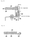
skin 48 has been properly positioned with respect toengageable members 56 such as clips by sewing (basting), the net-shapedskin 48 is joined at its periphery to theengageable members 56 by vibration welding for the fixing thereof to aportion 58 of a frame. Such construction enables the vibration-welded portions to support a large load applied to the net-shapedskin 48. - Furthermore, as shown in Fig. 35, the
engageable members 56 may be engaged with a fitting 62 of the frame. Alternatively, before the fitting 62 is mounted on the frame,rigid members 50 vibration-welded to the periphery of the net-shaped skin may be first inserted into the fitting 62, which can be in turn secured to the frame, as shown in Fig. 36, thereby imparting a desired tension to the net-shaped skin without using any tensioning jig. - As shown in Figs. 37 and 38, the
engageable members 56 may be sewn and vibration-welded to only thelower mesh layer 26 of the net-shaped skin and, under the condition in which only sewn portions of thepile layer 28 that connects the upper and lower mesh layers 24, 26 are compressed, the periphery of the net-shaped skin may be joined to one end of aside skin 60 by sewing. In this case, the other end of theside skin 60 is sewn and vibration-welded to therigid members 50, which are in turn engaged with the fitting 62 of the frame together with theengageable members 56. - Because this construction allows the
pile layer 28 other than the sewn portions to be held under an uncompressed condition, compression of the piles by the tensioning of the net is avoided. Accordingly, when a user sits on the net-shaped skin, deflection of the piles disperses his load and, also, he does not receive any feeling of foreign substances from the frame and the like. - As shown in Fig. 39, the
lower mesh layer 26 and theengageable members 56 may be joined together by extrusion-molding or injection-molding theengageable members 56 to end portions of thelower mesh layer 26. - A seat in which a plurality of net-shaped skins according to the present invention are laminated is discussed hereinafter with reference to Figs. 40 to 43.
- A seat S2 shown in Figs. 40 to 42 includes a
seat cushion 66 having a plurality of net-shaped skins laminated on pipe frames 64 and a seat back 68 similarly having a plurality of laminated net-shaped skins. - As shown in Fig. 43, each of the
seat cushion 66 and the seat back 68 employs the plurality of net-shaped skins as thefirst layer 70, the second layer 72, thethird layer 74, thefourth layer 76, thefifth layer 78, and thesixth layer 80, all of which are laminated one above the other in this order. Therigid members 40 as shown in Fig. 26 are inserted into the net-shapedskin 80 of the sixth layer. Any one of the second to sixth layers 72-80 may be an urethane layer. - In general, a thin urethane layer causes a bottom-end shock and, hence, a spring structure is normally imparted thereto or a highly elastic urethane is combined therewith. Although such a structure makes a cushion thick as a whole, a combination of the nets and urethane makes the cushion thinner than the conventional one and can cope with the bottom-end shock.
- As shown in Fig. 44, a plurality of (five in Fig. 42) rolled net-shaped
skins 82 may be arranged in a side-by-side fashion in place of the second to fifth layers 72-78 shown in Fig. 43. - The structure in which the plurality of net-shaped skins are laminated as shown in Fig. 43 or in which the rolled net-shaped skins are juxtaposed as shown in Fig. 44 can reduce the bottom-end shock that is received by a user on a seat and reduces a spring constant to thereby improve the vibration characteristics around the resonant points. It is possible to further improve the vibration characteristics around the resonant points by incorporating a different kind of material such as a damping material, viscoelastic urethane, highly elastic urethane, low-repulsive urethane or the like. It is also possible to make a seat comfortable or soft to sit on and have a relatively large stroke, thereby enhancing an initial feeling.
- Body pressure distributions when a subject has sat on the seat having the net-shaped skin according to the present invention are explained hereinafter.
- Figs. 45 and 46 show the body pressure distributions (subject weight: 50 kg) when no wires have been inserted into the honeycomb-shaped upper and lower mesh layers 24, 26 and when wires have been inserted as shown in Fig. 26 (wire interval: large), respectively. Figs. 47 and 48 similarly show the body pressure distributions (
subject weight 50 kg) when no wires have been inserted into the honeycomb-shaped upper and lower mesh layers 24, 26 and when wires have been inserted as shown in Fig. 26 (wire interval: small), respectively. As can be seen from the graphs of Figs. 45 to 48, the surface rigidity of the cushioning member having the net-shaped skin is increased by inserting the wires, and the increased surface rigidity disperses the body pressure to thereby reduce the local pressure. - Figs. 49 and 50 show body pressure distributions (subject weight: 50 kg) when the subject has sat on a laminated structure of the net-shaped skin showing the static characteristics of Fig. 19 and the net-shaped skin showing the static characteristics of Fig. 20 with no resinous members vibration-welded thereto and when the subject has sat on another laminated structure in which the resinous members have been vibration-welded thereto (only the lower layer), as shown in Fig. 30, respectively. As shown therein, the vibration welding of the resinous members makes each pile forming the pile layer resistant to deflection, which disperses the body pressure, thereby reducing the local pressure. Also, the elasticity of the cushioning member can be improved as a whole by making use of the elasticity of the resinous members, contributing to a reduction of the bottom-end shock.
- Figs. 51 and 52 show body pressure distributions (subject weight: 50 kg) when the subject has sat on a conventional seat employing urethane as a cushioning material and when he has sat on a wheelchair employing the laminated structure shown in Fig. 43, respectively. The laminated structure of the cushioning member according to the present invention effectively disperses the body pressure and reduces the local pressure.
- Figs. 53 and 54 show body pressure distributions (subject weight: 74 kg) when another subject has sat on a conventional wheelchair and when he has sat on the wheelchair employing the laminated structure shown in Fig. 43, respectively. The laminated structure of the cushioning member according to the present invention effectively disperses the body pressure and reduces the local pressure irrespective of the subject weight.
- Temperature and humidity characteristics are discussed hereinafter when a subject has sat on the conventional wheelchair and when he sat on the wheelchair having the laminated structure of the cushioning member according to the present invention.
- Fig. 55 shows several check points where temperature and humidity characteristics have been examined. Figs. 56 and 57 show the characteristics at point Cushion-A when the subject is a great sweater, while Figs. 58 and 59 show the characteristics at point Back-A when the subject is an average man (not a great sweater). The temperature and humidity of the atmosphere were 35°C and 65%, respectively.
- As can be seen from the graphs of Figs. 56 and 57, because the wheelchair according to the present invention is excellent in air permeability and heat dissipation properties, the temperature characteristics and the humidity characteristics are both improved as compared with the conventional wheelchair.
- A similar tendency has been recognized at point Cushion-B or point Back-B other than point Cushion-A and point Back-A, and the temperature and humidity characteristics are both improved at all points irrespective of subjects. In particular, when the subject is a great sweater, the body temperature is taken by vaporization of sweat and, hence, he feels very cool and comfortable.
- With the above-described construction, the present invention provides the following effects.
- Because a cushioning member according to the present invention includes a net-shaped skin tensioned over a frame, the air permeability is enhanced, and a seat or bed can be reduced in weight by incorporating the cushioning member thereinto. Also, because the net-shaped skin is of a three-layered structure including an upper mesh layer, a lower mesh layer, and a pile layer having a large number of piles that connect the upper and lower mesh layers, and because each of the piles is made of a single string, the cushioning member has desired cushioning characteristics by the action of the elasticity of each pile.
- When the frame and the net-shaped skin are both made of a thermoplastic resin and joined together by vibration welding, they can be easily and strongly joined within a short period of time without lowering the physical properties of threads or strings of the net-shaped skin. Also, because both the frame and the net-shaped skin are made of a thermoplastic resin, it is possible to make all-weather seats that can be employed in motorcycles exposed to rainwater or the like.
- Furthermore, when the net-shaped skin is made of a thermoplastic resin and joined to at least one holding member made of a thermoplastic resin by vibration welding, the holding member can be secured to a metal frame, which can be incorporated into an automotive seat that may receive an impact load. If the net-shaped skin is damaged, the skin and the holding member can be replaced together.
- Also, if the holding member is secured to the frame after the net-shaped skin has been secured at the periphery thereof to the holding member by a string, an optional material can be used for the holding member or the frame.
- If a resinous frame member is formed at the periphery of the net-shaped skin by insert molding and is secured to the above frame, a metal frame can be employed which can be incorporated into an automotive seat. In this case, if the net-shaped skin is damaged, the skin and the resinous frame member can be replaced together.
- Furthermore, when the pile layer has a cross texture as viewed in a specific direction, there is no directional property of inclination of piles, enhancing the rigidity and allowing the sewing.
- Because the net-shaped skin has non-linear static load-deflection characteristics and also has the smallest spring constant in a normal use region including a balanced point, the transient response characteristics and the frequency response characteristics can be both improved. That is, the acceleration and deflection are attenuated quickly with respect to input changes and, hence, the period of time to the steady state can be shortened.
- If rigid members or elastic members are disposed at predetermined intervals, the surface rigidity or the entire rigidity of the net-shaped skin can be increased, thereby reducing a bottom-end shock.
- When engageable members attached at the periphery of the net-shaped skin by sewing and vibration welding are engaged with a portion of a seat, not only can the positioning of the engageable members relative to the net-shaped skin be carried out by sewing, but a load applied to the seat can also be received by vibration-welded portions.
- Furthermore, when the engageable members are attached at the periphery of the lower mesh layer and engaged with a portion of a seat under the condition in which the pile layer other than the sewn portions is not compressed, no feeling of foreign substances is sensed at the periphery of the net-shaped skin. In this case, the engageable members can be readily attached at the periphery of the lower mesh layer by extrusion-molding or injection-molding.
- In addition, when a plurality of net-shaped skins laminated one above another or a plurality of rolled net-shaped skins arranged in a side-by-side fashion are incorporated into a seat, the seat can be made thin, reduces a bottom-end shock, and improves vibration characteristics around the balanced point, as compared with conventional structures.
Claims (19)
- A cushioning member having a net-shaped skin, which comprises a frame and a net-shaped skin tensioned over said frame, said net-shaped skin comprising an upper mesh layer, a lower mesh layer, and a pile layer having a large number of piles that connect said upper and lower mesh layers, each of said piles being made of a single string.
- The cushioning member having the net-shaped skin according to claim 1, wherein said frame and said net-shaped skin are each made of a thermoplastic resin, and both of them are joined together by vibration welding.
- The cushioning member having the net-shaped skin according to claim 1, wherein said frame is made of a metal, while said net-shaped skin is made of a thermoplastic resin, and wherein after said net-shaped skin has been joined to at least one holding member made of a thermoplastic resin, said holding member is secured to said frame.
- The cushioning member having the net-shaped skin according to claim 1, wherein after said net-shaped skin has been secured at a periphery thereof to a holding member by a string, said holding member is secured to said frame.
- The cushioning member having the net-shaped skin according to claim 1, wherein a resinous frame is formed at a periphery of said net-shaped skin by insert molding, and said resinous frame is secured to said frame.
- In a seat having a seat cushion and a seat back, at least one of said seat cushion and seat back comprises a frame and a net-shaped skin tensioned over said frame, said net-shaped skin comprising an upper mesh layer, a lower mesh layer, and a pile layer having a large number of piles that connect said upper and lower mesh layers, each of said piles being made of a single string.
- The seat having the net-shaped skin according to claim 6, wherein said frame and said net-shaped skin are each made of a thermoplastic resin, and both of them are joined together by vibration welding.
- The seat having the net-shaped skin according to claim 6, wherein said frame is made of a metal, while said net-shaped skin is made of a thermoplastic resin, and wherein after said net-shaped skin has been joined to at least one holding member made of a thermoplastic resin, said holding member is secured to said frame.
- The seat having the net-shaped skin according to claim 6, wherein after said net-shaped skin has been secured at a periphery thereof to a holding member by a string, said holding member is secured to said frame.
- The seat having the net-shaped skin according to claim 6, wherein a resinous frame is formed at a periphery of said net-shaped skin by insert molding, and said resinous frame is secured to said frame.
- In a seat having a seat cushion, a seat back and a head rest, at least one of said seat cushion, seat back and said head rest comprises a frame and a net-shaped skin tensioned over said frame, said net-shaped skin comprising an upper mesh layer, a lower mesh layer, and a pile layer having a large number of piles that connect said upper and lower mesh layers, each of said piles being made of a single string.
- A cushioning member having a net-shaped skin, wherein said net-shaped skin is of a three-layered structure comprising an upper mesh layer, a lower mesh layer, and a pile layer having a large number of piles that connect said upper and lower mesh layers, each of said piles being made of a single string, said pile layer presenting a cross texture as viewed in a predetermined direction.
- The cushioning member having the net-shaped skin according to claim 12, wherein said net-shaped skin has non-linear static load-deflection characteristics and also has at least three spring constants in a normal use region, a region smaller in load than said normal use region, and a region greater in load than said normal use region, and wherein the spring constant in said normal use region is set to a smallest one.
- The cushioning member having the net-shaped skin according to claim 12, further comprising rigid members or elastic members disposed at predetermined intervals in at least one direction, thereby increasing a surface rigidity or elasticity of said upper mesh layer.
- The cushioning member having the net-shaped skin according to claim 12, further comprising engageable members mounted on a periphery of said net-shaped skin by vibration welding, wherein said engageable members are mounted on a portion of a seat.
- The cushioning member having the net-shaped skin according to claim 12, further comprising engageable members mounted on a periphery of said lower mesh layer, wherein said engageable members are mounted on a portion of a seat with said pile layer being not compressed.
- The cushioning member having the net-shaped skin according to claim 16, wherein said engageable members are mounted on the periphery of said lower mesh layer by extrusion molding.
- A seat having a plurality of net-shaped skins laminated one upon another, wherein each of said net-shaped skins is of a three-layered structure comprising an upper mesh layer, a lower mesh layer, and a pile layer having a large number of piles that connect said upper and lower mesh layers, each of said piles being made of a single string, said pile layer presenting a cross texture as viewed in a predetermined direction.
- A seat having a plurality of rolled net-shaped skins arranged in a side-by-side fashion, wherein each of said net-shaped skins is of a three-layered structure comprising an upper mesh layer, a lower mesh layer, and a pile layer having a large number of piles that connect said upper and lower mesh layers, each of said piles being made of a single string, said pile layer presenting a cross texture as viewed in a predetermined direction.
Applications Claiming Priority (3)
| Application Number | Priority Date | Filing Date | Title |
|---|---|---|---|
| JP28879697 | 1997-10-21 | ||
| JP28879697 | 1997-10-21 | ||
| PCT/JP1998/004760 WO1999020159A1 (en) | 1997-10-21 | 1998-10-21 | Cushion and seat each having net-like skin |
Publications (3)
| Publication Number | Publication Date |
|---|---|
| EP1033098A1 true EP1033098A1 (en) | 2000-09-06 |
| EP1033098A4 EP1033098A4 (en) | 2001-03-21 |
| EP1033098B1 EP1033098B1 (en) | 2004-03-17 |
Family
ID=17734851
Family Applications (1)
| Application Number | Title | Priority Date | Filing Date |
|---|---|---|---|
| EP98950319A Expired - Lifetime EP1033098B1 (en) | 1997-10-21 | 1998-10-21 | Cushion and seat each having net-like skin |
Country Status (8)
| Country | Link |
|---|---|
| US (1) | US6315364B1 (en) |
| EP (1) | EP1033098B1 (en) |
| KR (1) | KR100377117B1 (en) |
| CN (1) | CN1124804C (en) |
| AU (1) | AU9645098A (en) |
| DE (1) | DE69822500T2 (en) |
| TW (1) | TW381996B (en) |
| WO (1) | WO1999020159A1 (en) |
Cited By (10)
| Publication number | Priority date | Publication date | Assignee | Title |
|---|---|---|---|---|
| EP1070470A1 (en) * | 1999-07-21 | 2001-01-24 | Delta Tooling Co., Ltd. | Structural unit having net member incorporated therein, seat and method for treating end section of net member |
| EP1193120A1 (en) * | 2000-10-02 | 2002-04-03 | Delta Tooling Co., Ltd. | Vehicle seat |
| WO2002052991A1 (en) | 2000-12-29 | 2002-07-11 | Vladimir Indic | Assembly of balls as an element of deck-chair, chair, back of a chair and arm-rest, and the process of assembling thereof |
| EP1388310A1 (en) * | 2001-05-16 | 2004-02-11 | Delta Tooling Co., Ltd. | Cushion structure |
| WO2004078002A2 (en) * | 2000-09-20 | 2004-09-16 | Dahti Inc. | Attachment of a carrier with load-bearing fabric to a frame |
| US6802566B2 (en) | 2000-09-28 | 2004-10-12 | Formway Furniture Limited | Arm assembly for a chair |
| WO2005020762A1 (en) * | 2003-08-28 | 2005-03-10 | Keter Plastic Ltd. | Furniture item and a method for attaching webbing thereto |
| EP1552771A1 (en) * | 2002-07-23 | 2005-07-13 | Okamura corporation | Construction for attaching net member to chair seat or backrest frame |
| US6926358B2 (en) * | 2001-12-20 | 2005-08-09 | Delta Tooling Co., Ltd. | Impact absorbing structure and seat structure |
| US11684530B2 (en) * | 2019-04-12 | 2023-06-27 | Hill-Rom Services, Inc. | Mattress retention assembly and radiofrequency weld in surface covers |
Families Citing this family (56)
| Publication number | Priority date | Publication date | Assignee | Title |
|---|---|---|---|---|
| JP2000325174A (en) * | 1999-05-18 | 2000-11-28 | Delta Tooling Co Ltd | Seat |
| JP2001087077A (en) * | 1999-09-20 | 2001-04-03 | Delta Tooling Co Ltd | Seat provided with three-dimensional net |
| JP4380896B2 (en) * | 2000-08-02 | 2009-12-09 | 株式会社デルタツーリング | Sheet |
| JP4584403B2 (en) * | 2000-04-13 | 2010-11-24 | 株式会社デルタツーリング | mat |
| NZ504871A (en) * | 2000-05-22 | 2002-04-26 | Miller Herman Inc | A chair with a preload mechanism to assist in the manufacture of reclining chairs so that the spring mechanism may be easily inserted |
| JP4666724B2 (en) * | 2000-07-10 | 2011-04-06 | 株式会社デルタツーリング | Folding seat |
| AUPR054400A0 (en) | 2000-09-29 | 2000-10-26 | Formway Furniture Limited | A castor |
| JP4484346B2 (en) * | 2000-09-29 | 2010-06-16 | 株式会社デルタツーリング | Vehicle seat |
| JP3592317B2 (en) | 2001-07-04 | 2004-11-24 | 株式会社豊田中央研究所 | Sheet |
| US7124844B2 (en) * | 2002-06-14 | 2006-10-24 | Bombardier Recreational Products Inc. | Straddle-type mesh seat |
| US10004342B2 (en) | 2002-12-17 | 2018-06-26 | Breathablebaby, Llc | Breathable toy |
| US20170367496A1 (en) * | 2016-06-28 | 2017-12-28 | Breathablebaby, Llc | Durable crib shield system |
| US10722049B2 (en) * | 2016-06-28 | 2020-07-28 | Breathablebaby, Llc | Reversible crib shield system |
| US9370255B2 (en) | 2002-12-17 | 2016-06-21 | Breathablebaby, Llc | Crib shield system and other breathable apparatus |
| US8793813B2 (en) | 2002-12-17 | 2014-08-05 | Breathablebaby, Llc | Breathable garment and method of use |
| US10588436B2 (en) | 2002-12-17 | 2020-03-17 | Breathablebaby, Llc | Breathable security blanket |
| US9451835B2 (en) | 2002-12-17 | 2016-09-27 | Breathablebaby, Llc | Breathable playmat |
| US9247830B2 (en) | 2002-12-17 | 2016-02-02 | Breathablebaby, Llc | Breathable pillow |
| US10694868B2 (en) * | 2016-06-28 | 2020-06-30 | Breathablebaby, Llc | Layered crib shield system |
| US9872577B2 (en) | 2002-12-17 | 2018-01-23 | Breathablebaby, Llc | Breathable pillow |
| AU2003299716A1 (en) | 2002-12-17 | 2004-07-14 | Dale Richard Waters | Crib shield system and other breathable apparatus |
| US7376991B2 (en) * | 2004-10-01 | 2008-05-27 | Midmark Corporation | Medical examination table |
| EP1858372B1 (en) * | 2005-03-01 | 2013-05-01 | Haworth, Inc. | Chair back |
| GB0511393D0 (en) * | 2005-06-04 | 2005-07-13 | Space Net Technology Ltd | A seating system |
| US7395590B2 (en) * | 2005-06-10 | 2008-07-08 | Haworth, Inc. | Method for assembling a frame assembly for a chair |
| US7461442B2 (en) * | 2005-06-10 | 2008-12-09 | Haworth, Inc. | Assembly apparatus and process for a chair back |
| US20070200417A1 (en) * | 2005-11-19 | 2007-08-30 | York Julie L | Seat cushion using vertically lapped fiber |
| US20070170759A1 (en) * | 2005-12-29 | 2007-07-26 | Graco Children's Products Inc. | Car Seat |
| US20070152488A1 (en) * | 2005-12-30 | 2007-07-05 | York Julie L | Arm rest using vertical lapped fiber |
| US7484811B2 (en) * | 2006-03-15 | 2009-02-03 | Chang James L | Apparatus for supporting a person and method of forming thereof |
| WO2007131214A2 (en) | 2006-05-04 | 2007-11-15 | Chang James L | Apparatus for supporting a person and method of forming thereof |
| EP2798977B1 (en) * | 2007-09-20 | 2017-11-08 | Herman Miller, Inc. | Load support structure |
| CA2950118C (en) * | 2008-12-12 | 2019-04-23 | Formway Furniture Limited | A chair, a support, and components |
| US20110133531A1 (en) * | 2009-12-09 | 2011-06-09 | Yeh Chia-Chang | Seat applicable to vehicles |
| US8646134B1 (en) | 2011-06-22 | 2014-02-11 | Bedgear, Llc | Pillow with gusset of open cell construction |
| PL2654514T3 (en) | 2012-03-02 | 2018-12-31 | Intex Marketing Ltd. | Inflatable product with internal tensioning structure |
| CN102578860B (en) * | 2012-03-02 | 2015-05-06 | 明达实业(厦门)有限公司 | Inflatable product lumen drawing tablet and manufacturing method thereof |
| CN102578859B (en) * | 2012-03-02 | 2014-11-05 | 明达实业(厦门)有限公司 | Slider structure of inflatable product and making method of slider structure |
| US9913540B2 (en) | 2012-09-21 | 2018-03-13 | Steelcase Inc. | Chair construction |
| US9155408B2 (en) | 2013-01-10 | 2015-10-13 | Bedgear, Llc | Pillow protector |
| US9149124B1 (en) * | 2013-04-04 | 2015-10-06 | Joseph Savovic | Engineered seating system for use in medical lift chairs |
| BE1022032B1 (en) * | 2013-07-12 | 2016-02-05 | Advanced Spring Technology, Naamloze Vennootschap | FOAM CONSTRUCTION AND MATTRESS OR CUSHION THEREOF |
| ES2964562T3 (en) | 2013-07-18 | 2024-04-08 | Intex Marketing Ltd | Inflatable hydrotherapy bath |
| CN103600502A (en) | 2013-11-25 | 2014-02-26 | 明达实业(厦门)有限公司 | Melting technology of inflatable products |
| US9463727B2 (en) * | 2014-08-14 | 2016-10-11 | Honda Motor Co., Ltd. | Vehicle seat covering assembly |
| CN110177489B (en) * | 2016-09-15 | 2023-02-03 | 克兹二世有限公司 | Child support device using layered net material |
| US10492624B2 (en) | 2017-09-15 | 2019-12-03 | Breathablebaby, Llc | Crib liner |
| US10472014B2 (en) * | 2018-01-12 | 2019-11-12 | Beto Engineering and Marketing Co., Ltd. | Baby seat of bicycle |
| EP3745924A4 (en) * | 2018-01-31 | 2021-09-15 | Bestway Inflatables & Material Corp. | Wraparound inflatable headboard apparatus and inflatable bed system |
| US11234521B2 (en) * | 2018-04-19 | 2022-02-01 | Rm Brands As | Foldable camping seat |
| CN109567476A (en) * | 2018-11-26 | 2019-04-05 | 湖州中祺智能科技有限公司 | A kind of seat cushion with resilient support function |
| DE202019107086U1 (en) * | 2019-12-18 | 2020-02-17 | Westfield Outdoors Gmbh | Seat cover for seating |
| CN111534029A (en) * | 2020-05-15 | 2020-08-14 | 浙江大东方椅业股份有限公司 | Composite modified material for mesh chair back |
| US11602225B2 (en) * | 2020-06-25 | 2023-03-14 | Haworth, Inc. | Knit seat back for an office chair |
| US11220196B1 (en) * | 2020-09-18 | 2022-01-11 | GM Global Technology Operations LLC | Multi-layer textile seat for dynamic conditions |
| DE102021117766A1 (en) | 2021-07-09 | 2023-01-12 | Audi Aktiengesellschaft | Seating device for a vehicle |
Citations (1)
| Publication number | Priority date | Publication date | Assignee | Title |
|---|---|---|---|---|
| US5013089A (en) * | 1989-09-15 | 1991-05-07 | General Motors Corporation | Thin profile integrated suspension and seat trim cover |
Family Cites Families (17)
| Publication number | Priority date | Publication date | Assignee | Title |
|---|---|---|---|---|
| JPS58144467A (en) | 1982-02-22 | 1983-08-27 | Sumitomo Electric Ind Ltd | Tool made of coated sintered hard alloy |
| JPS58144467U (en) * | 1982-03-26 | 1983-09-29 | 日本発条株式会社 | Seat skin locking device |
| JPS6031864A (en) | 1983-08-01 | 1985-02-18 | 井関農機株式会社 | Grain stirring apparatus of rotary grain separating apparatus |
| JPS6031864U (en) * | 1983-08-09 | 1985-03-04 | 東和織物株式会社 | Summer mattress |
| JPS6439052A (en) | 1987-08-05 | 1989-02-09 | Matsushita Electric Works Ltd | Pin grid array |
| JPS6439052U (en) * | 1987-09-04 | 1989-03-08 | ||
| JPH01158761A (en) | 1987-12-15 | 1989-06-21 | Fujitsu Ltd | Integrated circuit incorporating terminal resistance |
| JPH01158761U (en) * | 1988-04-22 | 1989-11-02 | ||
| JP2877866B2 (en) | 1989-03-22 | 1999-04-05 | 二三産業株式会社 | Sleeve tube mounting method |
| JPH0747633Y2 (en) * | 1989-06-29 | 1995-11-01 | 本田技研工業株式会社 | Winding transmission device |
| JP3017352B2 (en) | 1992-03-13 | 2000-03-06 | 富士通株式会社 | Supervisory control system and its sequence processing method |
| JP3208185B2 (en) | 1992-08-27 | 2001-09-10 | 三洋電機株式会社 | Component lead position recognition method and component mounting device using the same |
| US5378040A (en) * | 1993-01-22 | 1995-01-03 | Zoetech, Inc. | Adjustable geriatric chair |
| JPH0677699U (en) * | 1993-04-16 | 1994-11-01 | 有限会社テック | Seating structure for the seat and backrest of the chair |
| US5393126A (en) * | 1993-06-21 | 1995-02-28 | Art Design International Inc. | Tubular frame seating structure with tension sleeve |
| US5533789A (en) * | 1994-11-10 | 1996-07-09 | Milliken Research Corporation | Seating structure |
| JPH0970339A (en) | 1995-07-05 | 1997-03-18 | Asahi Chem Ind Co Ltd | Bedsore preventing mat |
-
1998
- 1998-10-20 TW TW087117314A patent/TW381996B/en not_active IP Right Cessation
- 1998-10-21 AU AU96450/98A patent/AU9645098A/en not_active Abandoned
- 1998-10-21 KR KR10-2000-7004340A patent/KR100377117B1/en not_active IP Right Cessation
- 1998-10-21 US US09/529,804 patent/US6315364B1/en not_active Expired - Lifetime
- 1998-10-21 DE DE69822500T patent/DE69822500T2/en not_active Expired - Lifetime
- 1998-10-21 WO PCT/JP1998/004760 patent/WO1999020159A1/en active IP Right Grant
- 1998-10-21 CN CN98810329A patent/CN1124804C/en not_active Expired - Fee Related
- 1998-10-21 EP EP98950319A patent/EP1033098B1/en not_active Expired - Lifetime
Patent Citations (1)
| Publication number | Priority date | Publication date | Assignee | Title |
|---|---|---|---|---|
| US5013089A (en) * | 1989-09-15 | 1991-05-07 | General Motors Corporation | Thin profile integrated suspension and seat trim cover |
Non-Patent Citations (1)
| Title |
|---|
| See also references of WO9920159A1 * |
Cited By (17)
| Publication number | Priority date | Publication date | Assignee | Title |
|---|---|---|---|---|
| EP1070470A1 (en) * | 1999-07-21 | 2001-01-24 | Delta Tooling Co., Ltd. | Structural unit having net member incorporated therein, seat and method for treating end section of net member |
| US6899398B2 (en) | 2000-09-20 | 2005-05-31 | Dahti, Inc. | Carrier and attachment method for load-bearing fabric |
| WO2004078002A2 (en) * | 2000-09-20 | 2004-09-16 | Dahti Inc. | Attachment of a carrier with load-bearing fabric to a frame |
| WO2004078002A3 (en) * | 2000-09-20 | 2004-12-16 | Dahti Inc | Attachment of a carrier with load-bearing fabric to a frame |
| US7096549B2 (en) | 2000-09-20 | 2006-08-29 | Dahti, Inc. | Carrier and attachment method for load-bearing fabric |
| US7798573B2 (en) | 2000-09-28 | 2010-09-21 | Formway Furniture Limited | Reclinable chair |
| US6802566B2 (en) | 2000-09-28 | 2004-10-12 | Formway Furniture Limited | Arm assembly for a chair |
| US6817667B2 (en) | 2000-09-28 | 2004-11-16 | Formway Furniture Limited | Reclinable chair |
| EP1193120A1 (en) * | 2000-10-02 | 2002-04-03 | Delta Tooling Co., Ltd. | Vehicle seat |
| WO2002052991A1 (en) | 2000-12-29 | 2002-07-11 | Vladimir Indic | Assembly of balls as an element of deck-chair, chair, back of a chair and arm-rest, and the process of assembling thereof |
| EP1388310A4 (en) * | 2001-05-16 | 2004-08-11 | Delta Tooling Co Ltd | Cushion structure |
| EP1388310A1 (en) * | 2001-05-16 | 2004-02-11 | Delta Tooling Co., Ltd. | Cushion structure |
| US6926358B2 (en) * | 2001-12-20 | 2005-08-09 | Delta Tooling Co., Ltd. | Impact absorbing structure and seat structure |
| EP1552771A1 (en) * | 2002-07-23 | 2005-07-13 | Okamura corporation | Construction for attaching net member to chair seat or backrest frame |
| EP1552771A4 (en) * | 2002-07-23 | 2008-04-09 | Okamura Corp | Construction for attaching net member to chair seat or backrest frame |
| WO2005020762A1 (en) * | 2003-08-28 | 2005-03-10 | Keter Plastic Ltd. | Furniture item and a method for attaching webbing thereto |
| US11684530B2 (en) * | 2019-04-12 | 2023-06-27 | Hill-Rom Services, Inc. | Mattress retention assembly and radiofrequency weld in surface covers |
Also Published As
| Publication number | Publication date |
|---|---|
| EP1033098A4 (en) | 2001-03-21 |
| DE69822500D1 (en) | 2004-04-22 |
| AU9645098A (en) | 1999-05-10 |
| US6315364B1 (en) | 2001-11-13 |
| CN1280467A (en) | 2001-01-17 |
| CN1124804C (en) | 2003-10-22 |
| DE69822500T2 (en) | 2004-08-12 |
| WO1999020159A1 (en) | 1999-04-29 |
| TW381996B (en) | 2000-02-11 |
| KR100377117B1 (en) | 2003-03-26 |
| EP1033098B1 (en) | 2004-03-17 |
| KR20010031346A (en) | 2001-04-16 |
Similar Documents
| Publication | Publication Date | Title |
|---|---|---|
| EP1033098B1 (en) | Cushion and seat each having net-like skin | |
| US7731294B2 (en) | Seat | |
| US7971939B2 (en) | Seat structure | |
| US6489000B1 (en) | Cushion having a three-dimensional net | |
| EP1084902B1 (en) | Seat having a three-dimensional net | |
| EP1733919B1 (en) | Base net supporting mechanism for seat and seat structure thereof | |
| EP1676745B1 (en) | Lumbar support, cushion for seat, and seat structure | |
| KR100499757B1 (en) | Seat structure | |
| US6435618B1 (en) | Seat | |
| US20020060493A1 (en) | Vehicle seat | |
| US20020096932A1 (en) | Vehicle seat | |
| JP2003182427A (en) | Shock absorbing structure and seat structure | |
| JP2002336076A (en) | Cushion structure | |
| JP4741759B2 (en) | Seat cushion structure | |
| EP1023861A1 (en) | Cushion structure having a three-dimensional net | |
| JP2004188164A (en) | Seat structure | |
| JP4711663B2 (en) | Seat cushion material and seat | |
| JP2003342859A (en) | Three-dimensional knitted fabric and sheet structure | |
| JP2005046355A (en) | Flat support member for seat | |
| JP2003306065A (en) | Seat |
Legal Events
| Date | Code | Title | Description |
|---|---|---|---|
| PUAI | Public reference made under article 153(3) epc to a published international application that has entered the european phase |
Free format text: ORIGINAL CODE: 0009012 |
|
| 17P | Request for examination filed |
Effective date: 20000522 |
|
| AK | Designated contracting states |
Kind code of ref document: A1 Designated state(s): DE FR GB |
|
| A4 | Supplementary search report drawn up and despatched |
Effective date: 20010206 |
|
| AK | Designated contracting states |
Kind code of ref document: A4 Designated state(s): DE FR GB |
|
| 17Q | First examination report despatched |
Effective date: 20020426 |
|
| RAP1 | Party data changed (applicant data changed or rights of an application transferred) |
Owner name: SUMINOE TEXTILE CO., LTD. Owner name: DELTA TOOLING CO., LTD. |
|
| GRAP | Despatch of communication of intention to grant a patent |
Free format text: ORIGINAL CODE: EPIDOSNIGR1 |
|
| GRAS | Grant fee paid |
Free format text: ORIGINAL CODE: EPIDOSNIGR3 |
|
| GRAA | (expected) grant |
Free format text: ORIGINAL CODE: 0009210 |
|
| AK | Designated contracting states |
Kind code of ref document: B1 Designated state(s): DE FR GB |
|
| REG | Reference to a national code |
Ref country code: GB Ref legal event code: FG4D |
|
| REF | Corresponds to: |
Ref document number: 69822500 Country of ref document: DE Date of ref document: 20040422 Kind code of ref document: P |
|
| ET | Fr: translation filed | ||
| PLBE | No opposition filed within time limit |
Free format text: ORIGINAL CODE: 0009261 |
|
| STAA | Information on the status of an ep patent application or granted ep patent |
Free format text: STATUS: NO OPPOSITION FILED WITHIN TIME LIMIT |
|
| 26N | No opposition filed |
Effective date: 20041220 |
|
| REG | Reference to a national code |
Ref country code: FR Ref legal event code: PLFP Year of fee payment: 19 |
|
| PGFP | Annual fee paid to national office [announced via postgrant information from national office to epo] |
Ref country code: FR Payment date: 20160913 Year of fee payment: 19 |
|
| PGFP | Annual fee paid to national office [announced via postgrant information from national office to epo] |
Ref country code: GB Payment date: 20161025 Year of fee payment: 19 Ref country code: DE Payment date: 20161103 Year of fee payment: 19 |
|
| REG | Reference to a national code |
Ref country code: DE Ref legal event code: R119 Ref document number: 69822500 Country of ref document: DE |
|
| GBPC | Gb: european patent ceased through non-payment of renewal fee |
Effective date: 20171021 |
|
| REG | Reference to a national code |
Ref country code: FR Ref legal event code: ST Effective date: 20180629 |
|
| PG25 | Lapsed in a contracting state [announced via postgrant information from national office to epo] |
Ref country code: GB Free format text: LAPSE BECAUSE OF NON-PAYMENT OF DUE FEES Effective date: 20171021 Ref country code: DE Free format text: LAPSE BECAUSE OF NON-PAYMENT OF DUE FEES Effective date: 20180501 |
|
| PG25 | Lapsed in a contracting state [announced via postgrant information from national office to epo] |
Ref country code: FR Free format text: LAPSE BECAUSE OF NON-PAYMENT OF DUE FEES Effective date: 20171031 |