EP1034931A1 - Ink jet type recording head - Google Patents
Ink jet type recording head Download PDFInfo
- Publication number
- EP1034931A1 EP1034931A1 EP00113487A EP00113487A EP1034931A1 EP 1034931 A1 EP1034931 A1 EP 1034931A1 EP 00113487 A EP00113487 A EP 00113487A EP 00113487 A EP00113487 A EP 00113487A EP 1034931 A1 EP1034931 A1 EP 1034931A1
- Authority
- EP
- European Patent Office
- Prior art keywords
- pressure generating
- head unit
- head
- generating chambers
- ink jet
- Prior art date
- Legal status (The legal status is an assumption and is not a legal conclusion. Google has not performed a legal analysis and makes no representation as to the accuracy of the status listed.)
- Granted
Links
Images


Classifications
-
- B—PERFORMING OPERATIONS; TRANSPORTING
- B41—PRINTING; LINING MACHINES; TYPEWRITERS; STAMPS
- B41J—TYPEWRITERS; SELECTIVE PRINTING MECHANISMS, i.e. MECHANISMS PRINTING OTHERWISE THAN FROM A FORME; CORRECTION OF TYPOGRAPHICAL ERRORS
- B41J2/00—Typewriters or selective printing mechanisms characterised by the printing or marking process for which they are designed
- B41J2/005—Typewriters or selective printing mechanisms characterised by the printing or marking process for which they are designed characterised by bringing liquid or particles selectively into contact with a printing material
- B41J2/01—Ink jet
- B41J2/135—Nozzles
- B41J2/145—Arrangement thereof
- B41J2/155—Arrangement thereof for line printing
-
- B—PERFORMING OPERATIONS; TRANSPORTING
- B41—PRINTING; LINING MACHINES; TYPEWRITERS; STAMPS
- B41J—TYPEWRITERS; SELECTIVE PRINTING MECHANISMS, i.e. MECHANISMS PRINTING OTHERWISE THAN FROM A FORME; CORRECTION OF TYPOGRAPHICAL ERRORS
- B41J2/00—Typewriters or selective printing mechanisms characterised by the printing or marking process for which they are designed
- B41J2/005—Typewriters or selective printing mechanisms characterised by the printing or marking process for which they are designed characterised by bringing liquid or particles selectively into contact with a printing material
- B41J2/01—Ink jet
- B41J2/135—Nozzles
- B41J2/14—Structure thereof only for on-demand ink jet heads
- B41J2/14201—Structure of print heads with piezoelectric elements
- B41J2/14233—Structure of print heads with piezoelectric elements of film type, deformed by bending and disposed on a diaphragm
-
- B—PERFORMING OPERATIONS; TRANSPORTING
- B41—PRINTING; LINING MACHINES; TYPEWRITERS; STAMPS
- B41J—TYPEWRITERS; SELECTIVE PRINTING MECHANISMS, i.e. MECHANISMS PRINTING OTHERWISE THAN FROM A FORME; CORRECTION OF TYPOGRAPHICAL ERRORS
- B41J2/00—Typewriters or selective printing mechanisms characterised by the printing or marking process for which they are designed
- B41J2/005—Typewriters or selective printing mechanisms characterised by the printing or marking process for which they are designed characterised by bringing liquid or particles selectively into contact with a printing material
- B41J2/01—Ink jet
- B41J2/135—Nozzles
- B41J2/14—Structure thereof only for on-demand ink jet heads
- B41J2/14201—Structure of print heads with piezoelectric elements
- B41J2/14274—Structure of print heads with piezoelectric elements of stacked structure type, deformed by compression/extension and disposed on a diaphragm
-
- B—PERFORMING OPERATIONS; TRANSPORTING
- B41—PRINTING; LINING MACHINES; TYPEWRITERS; STAMPS
- B41J—TYPEWRITERS; SELECTIVE PRINTING MECHANISMS, i.e. MECHANISMS PRINTING OTHERWISE THAN FROM A FORME; CORRECTION OF TYPOGRAPHICAL ERRORS
- B41J2/00—Typewriters or selective printing mechanisms characterised by the printing or marking process for which they are designed
- B41J2/005—Typewriters or selective printing mechanisms characterised by the printing or marking process for which they are designed characterised by bringing liquid or particles selectively into contact with a printing material
- B41J2/01—Ink jet
- B41J2/135—Nozzles
- B41J2/145—Arrangement thereof
-
- B—PERFORMING OPERATIONS; TRANSPORTING
- B41—PRINTING; LINING MACHINES; TYPEWRITERS; STAMPS
- B41J—TYPEWRITERS; SELECTIVE PRINTING MECHANISMS, i.e. MECHANISMS PRINTING OTHERWISE THAN FROM A FORME; CORRECTION OF TYPOGRAPHICAL ERRORS
- B41J2/00—Typewriters or selective printing mechanisms characterised by the printing or marking process for which they are designed
- B41J2/005—Typewriters or selective printing mechanisms characterised by the printing or marking process for which they are designed characterised by bringing liquid or particles selectively into contact with a printing material
- B41J2/01—Ink jet
- B41J2/135—Nozzles
- B41J2/14—Structure thereof only for on-demand ink jet heads
- B41J2002/14362—Assembling elements of heads
-
- B—PERFORMING OPERATIONS; TRANSPORTING
- B41—PRINTING; LINING MACHINES; TYPEWRITERS; STAMPS
- B41J—TYPEWRITERS; SELECTIVE PRINTING MECHANISMS, i.e. MECHANISMS PRINTING OTHERWISE THAN FROM A FORME; CORRECTION OF TYPOGRAPHICAL ERRORS
- B41J2/00—Typewriters or selective printing mechanisms characterised by the printing or marking process for which they are designed
- B41J2/005—Typewriters or selective printing mechanisms characterised by the printing or marking process for which they are designed characterised by bringing liquid or particles selectively into contact with a printing material
- B41J2/01—Ink jet
- B41J2/135—Nozzles
- B41J2/14—Structure thereof only for on-demand ink jet heads
- B41J2002/14419—Manifold
-
- B—PERFORMING OPERATIONS; TRANSPORTING
- B41—PRINTING; LINING MACHINES; TYPEWRITERS; STAMPS
- B41J—TYPEWRITERS; SELECTIVE PRINTING MECHANISMS, i.e. MECHANISMS PRINTING OTHERWISE THAN FROM A FORME; CORRECTION OF TYPOGRAPHICAL ERRORS
- B41J2202/00—Embodiments of or processes related to ink-jet or thermal heads
- B41J2202/01—Embodiments of or processes related to ink-jet heads
- B41J2202/11—Embodiments of or processes related to ink-jet heads characterised by specific geometrical characteristics
-
- B—PERFORMING OPERATIONS; TRANSPORTING
- B41—PRINTING; LINING MACHINES; TYPEWRITERS; STAMPS
- B41J—TYPEWRITERS; SELECTIVE PRINTING MECHANISMS, i.e. MECHANISMS PRINTING OTHERWISE THAN FROM A FORME; CORRECTION OF TYPOGRAPHICAL ERRORS
- B41J2202/00—Embodiments of or processes related to ink-jet or thermal heads
- B41J2202/01—Embodiments of or processes related to ink-jet heads
- B41J2202/19—Assembling head units
-
- B—PERFORMING OPERATIONS; TRANSPORTING
- B41—PRINTING; LINING MACHINES; TYPEWRITERS; STAMPS
- B41J—TYPEWRITERS; SELECTIVE PRINTING MECHANISMS, i.e. MECHANISMS PRINTING OTHERWISE THAN FROM A FORME; CORRECTION OF TYPOGRAPHICAL ERRORS
- B41J2202/00—Embodiments of or processes related to ink-jet or thermal heads
- B41J2202/01—Embodiments of or processes related to ink-jet heads
- B41J2202/20—Modules
Definitions
- the present invention relates to an ink jet type recording head and an ink jet printer.
- a piezoelectric vibrator or other pressure generating means is provided in a region of a pressure generating chamber communicating with a nozzle opening. Ink drops are generated when the pressure generating chamber is compressed by the deflection vibration of the piezoelectric vibrator or other pressure generating means.
- the manufacturing yield for ink jet type recording heads is much lower than the yield for wire-impact type recording heads or thermal transfer type recording heads.
- a recording head as follows.
- the recording head itself is made In such a manner that the number of nozzle openings is relatively small.
- the thus formed recording head is then used as a unit together with additional units, and the plurality of units are formed into one body and fixed onto a base board piece, to produce one recording head.
- the followinq problems may be encountered in the above recording head.
- the width of the side walls of adjacent units is larger than the pitch of the arrangement of nozzle openings. Accordingly, it is necessary to arrange the units in a zigzag pattern by shifting every other unit laterally by a distance corresponding to the width of one unit. As a result, the width of the recording head becomes, at a minimum, twice as great as that of an individual unit.
- the present invention has been accomplished in view of the above problems. It is therefore an object of the present invention to provide an ink jet recording head composed of a plurality of individual units in which the number of nozzles per recording head can be increased without significantly increasing the width of the recording head overall.
- a head unit according to independent claim 1 an ink jet type recording head according to independent claim 14 and an ink jet printer according to independent claim 20. Further advantageous features, aspects and details of the invention are evident from the dependent claims, the description and the drawings. The claims are intended to be understood as a first non-limiting approach of defining the invention in general terms.
- the invention provides an ink jet type recording head having head units with angled walls and angled pressure generating chambers.
- an ink jet type recording head comprising a plurality of head units, each said head unit comprising a plurality of pressure generating means and a plurality of pressure generating chambers for pressurizing ink through actuation of said pressure generating means.
- the plurality of head units house said plurality of pressure generating chambers.
- a flow passage unit includes a base board on which said head units are arranged, and a nozzle plate includes nozzle opening lines.
- the base board there are provided reservoirs and nozzle communication holes for feeding ink in accordance with the actuator units to nozzle openings which are provided in nozzle opening lines of a nozzle plate underlying the base board.
- the reservoirs are U shaped and arranged such that the arms of each U sandwich the lines of the nozzle communication holes.
- the pressure generating chambers are preferably arranged in line in an arrangement direction, and each chamber is preferably inclined at an angle ⁇ with respect to the arrangement direction. Outer edges of the head Units in the arrangement direction are preferably also inclined by an angle ⁇ with respect to the arrangement direction of the pressure generating chambers.
- the head units are advantageously arranged in a pattern such that each unit is shifted along the inclination of an adjacent unit away from a midline position of the adjacent unit.
- the arrangement of units according to a further preferred aspect is then fixed onto a base board so that the pitch between the pressure generating chambers opposing the outer edges in the arrangement direction of the pressure chambers is the same as that between the pressure generating chambers on
- opposing outer walls of adjacent head units are also inclined with respect to a straight line perpendicular to the arrangement direction of the pressure generating chambers. Accordingly, when the head units are shifted along the incline of the outer walls, a distance between adjacent head units in the arrangement direction of the pressure generating chambers is changed. Accordingly, an interval between the pressure generating chambers of respective adjacent units can be changed in the arrangement direction of the pressure generating chambers in accordance with the amount of shift between the adjacent units. Due to the foregoing, the head units need not be staggered in a full zigzag pattern, and the width of the recording head can be reduced. Therefore, the increase in the width of the recording head is minimal in light of the large number of head units arranged on the recording head.
- an ink jet printer which comprises an ink jet type recording head according to the above description.
- Fig. 1 illustrates a first embodiment of a recording head according to the present invention.
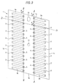
- Fig. 2 is a view showing an example of one head unit provided in the recording head.
- reference numeral 1 designates a spacer,
- the spacer is preferably composed of a base board made of ceramics such as zirconia (ZrO 2 ).
- the thickness of the spacer 1 should be appropriate for forming pressure generating charters 2, 3, the depth of which is preferably approximately 150 ⁇ m.
- the pressure generating chambers 2, 3 provided in the base board 1 are arranged in such a manner that a longitudinal axial line of each pressure generating chamber forms an acute angle ⁇ with respect to the arrangement direction of the nozzle openings 4, 5.
- the acute angle ⁇ is preferably set to be greater than 45 degrees and less than 90 degrees (i.e. 45° ⁇ ⁇ ⁇ 90°).
- An illustrative longitudinal axial line is shown in Fig. 3 at D - D, while the arrangement direction is illustrated by arrangement lines A - A and B - B.
- Outer walls 1a, 1b, forming an outer periphery of the spacer 1 near the pressure generating chambers 2a, 2b, 3a, 3b, located adjoining to these walls are approximately parallel to the axial lines of the pressure generating chambers 2, 3. Also, the remaining outer walls 1c, 1d, which are located on the tight and left in Fig. 3, are approximately parallel to the arrangement lines A - A and B - B of the nozzle openings.
- the outer walls 1a, 1b are constructed so that the end widths W1, W2 are reduced as much as possible.
- the lengths of the pressure generating chambers 2, 3 can be increased so that they are longer than comparable, conventional pressure generating chambers that are arranged perpendicularly to the nozzle opening arrangement lines A - A and B - B. Due to the foregoing, even when the width of the recording head must be reduced, e.g., to increase recording head density, it is nonetheless possible to ensure that each pressure generating chamber has a sufficiently large ink capacity.
- reference numeral 6 designates a diaphragm, which preferably is composed of a sheet of zirconia and has a thickness of, e.g., 10 ⁇ m. Therefore, when the diaphragm 6 is baked integrally with the spacer 1, a sufficiently high joining force can be achieved. If the diaphragm is composed of a sheet of zirconia, just like the spacer 1 is, it can be elastically deformed when piezoelectric vibrators 7, 8 are actuated.
- Reference numerals 7, 8, designate the piezoelectric vibrators mentioned above.
- the piezoelectric vibrators 7, 8 are preferably made by sintering a green sheet of piezoelectric material onto a surface of drive electrodes 9, 10 formed on a surface of the diaphragm 6.
- a cover sheet is integrally adhered onto the other surface of the spacer 1.
- the cover sheet 12 is preferably made of a sheet of zirconia, the thickness of which is, e.g., 150 ⁇ m.
- through-holes 13, 14 connect the nozzle openings 4, 5 of the nozzle plate 28 with the pressure generating chambers 2, 3.
- through-holes 17, 18 connect reservoirs 15, 16 with the pressure generating chambers 2, 3.
- Reference numeral 19 indicates an ink feed passage composing sheet, which is preferably made of a sheet member, such as a stainless steel sheet having the anticorrosion property, and which has a thickness of e.g. 150 ⁇ m or so.
- a sheet member such as a stainless steel sheet having the anticorrosion property
- the reservoirs 15, 16 are respectively connected with ink feed ports 22, 23 formed on the cover sheet 12. Therefore, the reservoirs 15, 16 receive ink from an ink tank arranged outside the recording head and feed it to the pressure generating chambers 2, 3 via the through-holes 17, 18.
- the recording head includes members 1, 6, 12 and 19.
- the members 1, 6 and 12 are preferably made of ceramics such that they can be integrated into one body by means of baking.
- the member 19 is advantageously made of metal and is joined to the ceramic elements by an appropriate conventional method. In this way, these members are incorporated into a head unit 27.
- holes 30, 31 used for positioning are provided substantially on a center line between the pressure generating chambers 2, 3. Due to the presence of the positioning holes 30, 31, even if the entire head unit contracts in the process of baking, the head unit can be correctly positioned at a reference position.
- Figs. 1, 5 and 7 show a nozzle plate at reference numeral 28.
- the nozzle plate 28 also functions as a fixing base board of the head unit.
- two sets of nozzle openings 4, 5 and 4', 5' are provided on the nozzle plate 28.
- An interval between the nozzle openings 4 and 5 is set to a constant value L; likewise, an interval between the nozzle openings 4' and 5' is set to a constant value L.
- the nozzle openings 4' are shifted over from the nozzle openings 4 by a distance ⁇ L in the scanning direction
- the nozzle openings 5' are shifted from the nozzle openings 5 by the same distance ⁇ L in the scanning direction.
- the shift distance ⁇ L is determined so that the head units 40, 41 do not overlap each other when they are fixed as shown in Fig. 5. Also, the shift distance ⁇ L is set so that the pitch of the nozzle openings in the paper feed direction is a constant value P0 even in a region where the units 40 and 41 oppose each other. In other words, the shift distance ⁇ L is determined so that the pitch of nozzle openings 4-1, 5-1 in particular, relative to the nozzle openings 4'-1, 5'-1, is the same as the pitch of the nozzle openings in other regions. More specifically, the shift amount ⁇ L is preferably no more than 80% of the distance from the outer wall 1c to the outer wall 1d.
- the first head unit 40 and the second head unit 41 are shifted relative to each other by a lateral distance ⁇ L so that an interval P1 between the lowermost nozzle opening of the first head unit 40 and the uppermost nozzle opening of the second head unit 41 is the same as the pitch P0 for the sets of nozzle openings 4, 5 and 4', 5'.
- a gap ⁇ G can be provided in the boundary; to produce the desired identity in pitch P1 and P0.
- the first and the second head unit are then fixed onto the nozzle plate 28.
- the lower outer wall 1b of the first head unit 40 and the upper outer wall 1a of the second head unit 41 are respectively inclined by an angle ⁇ with respect to the arrangement lines A-A and B-B.
- the first and the second head unit are disposed slightly offset but still adjacent to each other in the upward and downward direction. Accordingly, it is possible to make the pitch P1 in the boundary coincide with the pitch P0 in the scanning direction by a shift distance ⁇ L which is shorter than the width of an entire unit (40, 41).
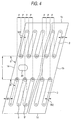
- Reference numerals 42 to 45 in Fig. 7 designate ink feed pipes to feed ink from the ink tank to the reservoirs 15, 16.
- printing signals are sent to the first head unit 40 and the second head unit 41, they are sent in timed relation so that the signal for the latter unit is shifted by a period of time corresponding to the number of dots which corresponds to the interval ⁇ L.
- the recording head constructed as described above can conduct printing in the same manner as can a recording head in which nozzle openings are formed along the same straight line.
- the recording head is composed of two head units.
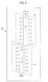
- three or more head units 50, 50, constructed as those described above, may be arranged in a column, as shown in Fig. 8.
- a plurality of columns may be arranged.
- a shift ⁇ L' results between an upper end and a lower end of the column of head units. Due to the foregoing, a triangular dead space is formed.
- the head units 54, 55 are arranged in the same manner as described above. That is, one head unit extends downward with respect to the center line C, and the other head unit extends upward with respect to the center line C.
- the nozzle openings 51, 52 are located on a line of the nozzle openings 53 formed by the head unit 50 in the moving direction of the recording head.
- Inks of different colors such as cyan, magenta and yellow inks, are respectively jetted out from two lines of nozzles which are continuously formed substantially linearly. Also, black ink is jetted out from two lines of nozzle openings which are divided to the right and left.
- Fig. 8(b) Due to the foregoing construction, as shown in Fig. 8(b), it is possible to arrange a large number of head units in line without changing the number of lines of nozzle openings. Also, the dead space is effectively utilized and the width of the recording head is not increased. In this connection, even in the recording head in which one line of nozzle openings is divided into two in the width direction, when the printing time is adjusted, it is possible to form dots in accordance with the printing position of the continuously formed nozzle opening line.
- the recording head is constructed as follows.
- the actuator unit 1 and the flow passage unit 12 are joined into one body in this way and arranged on the nozzle forming base board 28 in a predetermined manner, the recording head is completed.
- a recording head as follows. As shown in Figs. 9 and 10, one surface of the spacer 1 is sealed with the diaphragm 6 having piezoelectric vibrators 7, 8. The other surface of the spacer 1 is sealed with the cover member 60 having ink feed ports 61, 62 and nozzle communicating holes 63, 64, to thereby construct the actuator unit 65.
- This actuator unit 65 is fixed in the common flow passage unit 85, which also functions as a fixing base board. According to the above construction, it is possible to provide the same effect and benefits achieved by the previous embodiment.
- a plurality of stages of nozzle opening lines in this example, two stages of nozzle opening lines, are provided.
- Each stage of nozzle opening lines is composed of two lines of nozzle openings 70, 71, 70', 71' communicating with the actuator units 65, 65'.
- a plurality of sets of nozzle opening lines 70, 71, 70', 71', in this example, 3 sets of nozzle opening lines 70, 71, 70', 71', are provided in the paper width direction.
- a relation between the nozzle opening lines 70, 71 and the nozzle opening lines 70', 71', arranged in the paper feed direction is determined as follows.
- one head unit and the other head unit are shifted relative to each other so that an interval between the lowermost nozzle opening of the nozzle opening lines 70, 71 and the uppermost nozzle opening of the nozzle opening lines 70', 71' is the same as the pitch for each set of nozzle openings.
- the nozzle plate 72 results.
- a reservoir-forming base board 73 cooperating with the nozzle plate 72, there are provided reservoirs 74, 74' and nozzle communicating holes 75, 76, 75', 76' for feeding ink in accordance with the actuator units 65, 65'.
- a cover member 77 seals the other surface of the reservoir forming base board 73, and is provided with nozzle communicating holes 78, 79, 78', 79' and ink feed ports 80, 81, 80', 81' in the same manner. When they are laminated, the flow passage unit 85 is constructed.
- the actuator units 65, 65' are positioned in accordance with the nozzle communicating holes 75, 76, 75', 76' and the ink feed ports 80, 81, 80', 81' of the flow passage unit 85, and the ink feed ports 86, 86' communicating with the reservoirs 74, 74'.
- the flow passage unit 85 and units 65, 65' are integrally fixed into the holder 88 by means of windows 87, the recording head is constructed.
- reference numerals 89, 90, 89', 90' are recess portions formed at positions opposed to the reservoirs 74, 74', for the purpose of forming thin portions so that a compliance can be given to the reservoirs 74, 74'.
- two lines of nozzle openings are provided in the head unit.
- the present invention can be applied to a head unit in which only a single line or three or more lines of nozzle openings are provided.
- the pressure generating means includes a piezoelectric vibrator which performs deflection vibrations.
- the present invention is not limited to the above pressure generating means, and various other types of pressure generating means may be adopted.
- the diaphragm 6 for sealing the pressure generating chamber 2 is composed of a piezoelectric vibrating layer 101 formed as one piece, and the common electrode 100 is formed on the lower surface of the piezoelectric vibrating layer 101 over the entire region, or at least in regions opposing the pressure generating chamber 2.
- the individual electrodes 102 are respectively formed in regions opposing each pressure chamber 2 on the upper surface of the layer 101. Then, drive signals are selectively imparted to the, common electrode 100 and the individual electrodes 102 on the piezoelectric layer 101 facing the various pressure generating chambers 2, to jet out ink drops by means of the resulting deflection displacement.
- the above piezoelectric vibrating layer 101 can be easily made by a method appropriate for forming piezoelectric material into a sheet of film. Examples of usable methods are described below. For instance, piezoelectric material is baked to product a sheet. Alternatively piezoelectric material may be spattered onto a surface of conductive material, such as a metal sheet, to be used as a common electrode 100. According to yet another alternative, piezoelectric material may be placed onto a surface of conductive material by a hydrothermal method.
- the diaphragm 6 is formed as a common electrode 103 made of a metal sheet having both conductivity and elasticity.
- a piezoelectric vibrator 104 and an individual electrode 105 corresponding to each pressure generating chamber 2 are mounted on the pressure generating chamber side 2 of this common electrode 103.
- a sheet of material capable of being elastically deformed, for example, a sheet of zirconia may be laminated onto a surface of the common electrode 103.
- a Joule heat generating element 107 is provided on a surface of the diaphragm 6 to seal the spacer 1 on the pressure generating chamber 2 side.
- the element 107 may be provided on a surface of another member to define the pressure generating chamber 2 on the pressure generating chamber side.
- an ink protective layer 108 can be formed on the Joule heat generating element 107.
- piezoelectric vibrators 110, 110 having a longitudinal vibration mode are fixed to the base board 111 so that front ends of piezoelectric vibrators contact the diaphragm 6. Due to the above construction, when the piezoelectric vibrators 110, 110 are linearly displaced, the pressure generating chambers 2, 3 expand and contract accordingly.
- a plurality of pressure generating chambers in which ink is pressurized by pressure generating means are arranged in a column.
- the individual pressure generating chambers are inclined at an angle ⁇ with respect to the arrangement direction of the pressure chambers.
- an end surface of the head unit in the arrangement direction of the pressure chambers is inclined by the same angle ⁇ with respect to the arrangement direction of the pressure chambers.
- the pitch between the last pressure generating chamber on one unit and, the first pressure generating chamber on the adjacent unit in the arrangement direction can be made to equal the pitch between the pressure generating chambers on the individual units. Accordingly, by moving the head unit laterally along the outer wall of the adjacent head unit, a pitch distance in the arrangement direction of the pressure generating chamber can be adjusted to achieve this equality. As a result, it is possible to arrange a plurality of head units without unduly increasing the width of the recording head.
- the length of the pressure generating chambers can be increased in relation to comparable pressure generating chambers that are arranged on a line perpendicular to the arrangement line of the nozzle openings. Therefore, it is possible to enhance the density of the pressure chamber arrangement without reducing the volume of individual chambers.
Abstract
characterized in that
reservoirs (15, 16) for supplying ink to the pressure generating chambers (2, 3) are provided on the base board (19)
whith the reservoirs (15, 16, 74, 74' ) being arranged at both sides of at least one line defined by an arrangement direction of the pressure generating chambers (2, 3) such that the reservoirs oppose each other.

Description
- The present invention relates to an ink jet type recording head and an ink jet printer. In such an ink jet type recording head a piezoelectric vibrator or other pressure generating means is provided in a region of a pressure generating chamber communicating with a nozzle opening. Ink drops are generated when the pressure generating chamber is compressed by the deflection vibration of the piezoelectric vibrator or other pressure generating means.
- In order to conduct printing at high speed and high density, it would be desirable to increase the number of nozzle openings per recording head. In an ink jet type recording head, since liquid such as ink is treated in the nozzle openings, the pressure generating chamber, etc., it is necessary to manufacture the nozzle openings and ink passages of the recording head with high accuracy and with great uniformly. In an ink jet type recording, a liquid ink drop is projected toward and deposited on a recording medium. The amount of dispersion of the ink droplet is easily influenced by variations in the accuracy of the pressure generating chamber. Furthermore, a curvature in the trajectory of the ink droplet may result from inaccuracies in the nozzle openings.
- When even one of the nozzle openings or passages is out of alignment, the printing quality of the recording head markedly deteriorates, and the recording head becomes useless. Therefore, the manufacturing yield for ink jet type recording heads is much lower than the yield for wire-impact type recording heads or thermal transfer type recording heads.
- In order to solve the above problems, it is possible to construct a recording head as follows. The recording head itself is made In such a manner that the number of nozzle openings is relatively small. The thus formed recording head is then used as a unit together with additional units, and the plurality of units are formed into one body and fixed onto a base board piece, to produce one recording head. However, the followinq problems may be encountered in the above recording head. The width of the side walls of adjacent units is larger than the pitch of the arrangement of nozzle openings. Accordingly, it is necessary to arrange the units in a zigzag pattern by shifting every other unit laterally by a distance corresponding to the width of one unit. As a result, the width of the recording head becomes, at a minimum, twice as great as that of an individual unit.
- The present invention has been accomplished in view of the above problems. It is therefore an object of the present invention to provide an ink jet recording head composed of a plurality of individual units in which the number of nozzles per recording head can be increased without significantly increasing the width of the recording head overall.
- This object is solved by a head unit according to
independent claim 1, an ink jet type recording head according toindependent claim 14 and an ink jet printer according toindependent claim 20. Further advantageous features, aspects and details of the invention are evident from the dependent claims, the description and the drawings. The claims are intended to be understood as a first non-limiting approach of defining the invention in general terms. The invention provides an ink jet type recording head having head units with angled walls and angled pressure generating chambers. - In order to solve the above problems, the present invention according to a preferred aspect provides an ink jet type recording head comprising a plurality of head units, each said head unit comprising a plurality of pressure generating means and a plurality of pressure generating chambers for pressurizing ink through actuation of said pressure generating means. The plurality of head units house said plurality of pressure generating chambers.
- Furthermore, a flow passage unit includes a base board on which said head units are arranged, and a nozzle plate includes nozzle opening lines.
- On the base board there are provided reservoirs and nozzle communication holes for feeding ink in accordance with the actuator units to nozzle openings which are provided in nozzle opening lines of a nozzle plate underlying the base board. The reservoirs are U shaped and arranged such that the arms of each U sandwich the lines of the nozzle communication holes. The pressure generating chambers are preferably arranged in line in an arrangement direction, and each chamber is preferably inclined at an angle with respect to the arrangement direction. Outer edges of the head Units in the arrangement direction are preferably also inclined by an angle with respect to the arrangement direction of the pressure generating chambers. The head units are advantageously arranged in a pattern such that each unit is shifted along the inclination of an adjacent unit away from a midline position of the adjacent unit. The arrangement of units according to a further preferred aspect is then fixed onto a base board so that the pitch between the pressure generating chambers opposing the outer edges in the arrangement direction of the pressure chambers is the same as that between the pressure generating chambers on the individual head units themselves.
- In the above arrangement, it can be advisable that opposing outer walls of adjacent head units are also inclined with respect to a straight line perpendicular to the arrangement direction of the pressure generating chambers. Accordingly, when the head units are shifted along the incline of the outer walls, a distance between adjacent head units in the arrangement direction of the pressure generating chambers is changed. Accordingly, an interval between the pressure generating chambers of respective adjacent units can be changed in the arrangement direction of the pressure generating chambers in accordance with the amount of shift between the adjacent units. Due to the foregoing, the head units need not be staggered in a full zigzag pattern, and the width of the recording head can be reduced. Therefore, the increase in the width of the recording head is minimal in light of the large number of head units arranged on the recording head.
- In a further aspect of the invention an ink jet printer is provided which comprises an ink jet type recording head according to the above description.
- Fig. 1 is a cross-sectional view of a first embodiment of an ink jet type recording head according to the present invention, wherein the view shows a portion close to a pressure generating chamber.
- Fig. 2 is a perspective view showing an assembly process for the head unit shown in Fig. 1.
- Fig. 3 is a front view of an example of a spacer used in the head unit.
- Fig. 4 is an enlarged front view of an end portion of the spacer.
- Fig. 5 is a front view of an example of a nozzle plate used as a base board, on which the head units are mounted.
- Fig. 6 is a front view showing a positional relation between two head units which have been arranged adjacent each other so as to provide a recording head.
- Fig. 7 is a perspective view showing an ink jet type recording head according to the present invention.
- Fig. 8(a) is a view showing another example of the head unit arrangement according to the present invention, and Fig. 8(b) is a view showing another example of the nozzle opening arrangement according to the present invention.
- Fig. 9 is a cross-sectional view of another embodiment of the recording head according to the invention, wherein the view shows a portion close to the pressure generating chamber.
- Fig. 10 is a perspective view showing an assembly process for an actuator according to the present invention, suitable for the recording head of Fig. 9.
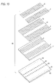
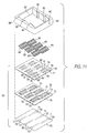
- Fig. 11 is an exploded perspective view showing an example of a flow passage unit suitable for constructing a recording head having an actuator unit of the type shown in Fig. 10.
- Fig. 12 shows another embodiment of a pressure generating means applicable to the present invention.
- Fig. 13 is a view showing a further embodiment of the pressure generating means applicable to the present invention.
- Fig. 14 shows yet another embodiment of the pressure generating means applicable to the present invention.
- Fig. 15 is a view showing another embodiment of the pressure generating means applicable to the present invention.
-
- Referring to various embodiments illustrated in the accompanying drawings, the present invention will now be explained in detail.
- Fig. 1 illustrates a first embodiment of a recording head according to the present invention. Fig. 2 is a view showing an example of one head unit provided in the recording head. In the drawing,
reference numeral 1 designates a spacer, The spacer is preferably composed of a base board made of ceramics such as zirconia (ZrO2). The thickness of thespacer 1 should be appropriate for formingpressure generating charters pressure generating chambers base board 1 are arranged in such a manner that a longitudinal axial line of each pressure generating chamber forms an acute angle with respect to the arrangement direction of thenozzle openings -
Outer walls spacer 1 near thepressure generating chambers pressure generating chambers outer walls outer walls - When the
pressure generating chambers pressure generating chambers pressure generating chambers - Referring again to Figs. 1 and 2,
reference numeral 6 designates a diaphragm, which preferably is composed of a sheet of zirconia and has a thickness of, e.g., 10 µm. Therefore, when thediaphragm 6 is baked integrally with thespacer 1, a sufficiently high joining force can be achieved. If the diaphragm is composed of a sheet of zirconia, just like thespacer 1 is, it can be elastically deformed whenpiezoelectric vibrators -
Reference numerals piezoelectric vibrators drive electrodes diaphragm 6. - In Figs. 1-2, a cover sheet, indicated at 12, is integrally adhered onto the other surface of the
spacer 1. In this example, thecover sheet 12 is preferably made of a sheet of zirconia, the thickness of which is, e.g., 150 µm. On thecover sheet 12, through-holes nozzle openings nozzle plate 28 with thepressure generating chambers holes reservoirs pressure generating chambers -
Reference numeral 19 indicates an ink feed passage composing sheet, which is preferably made of a sheet member, such as a stainless steel sheet having the anticorrosion property, and which has a thickness of e.g. 150 µm or so. On the ink feedpassage composing sheet 19, there are formed both through-holes which function asreservoirs holes pressure generating chambers nozzle openings - The
reservoirs ink feed ports cover sheet 12. Therefore, thereservoirs pressure generating chambers holes - As described above, the recording head includes
members members member 19 is advantageously made of metal and is joined to the ceramic elements by an appropriate conventional method. In this way, these members are incorporated into ahead unit 27. - As illustrated, e.g., in Figs. 3-5, holes 30, 31 used for positioning, are provided substantially on a center line between the
pressure generating chambers - Figs. 1, 5 and 7 show a nozzle plate at
reference numeral 28. In the present embodiment, thenozzle plate 28 also functions as a fixing base board of the head unit. On thenozzle plate 28, two sets ofnozzle openings nozzle openings nozzle openings 4 by a distance ΔL in the scanning direction, and the nozzle openings 5' are shifted from thenozzle openings 5 by the same distance ΔL in the scanning direction. - In this case, the shift distance ΔL is determined so that the
head units units outer wall 1c to theouter wall 1d. - In the head unit constructed as described above, as shown in Figs. 6 and 7, the
first head unit 40 and thesecond head unit 41 are shifted relative to each other by a lateral distance ΔL so that an interval P1 between the lowermost nozzle opening of thefirst head unit 40 and the uppermost nozzle opening of thesecond head unit 41 is the same as the pitch P0 for the sets ofnozzle openings nozzle plate 28. - In this case, the lower
outer wall 1b of thefirst head unit 40 and the upperouter wall 1a of thesecond head unit 41 are respectively inclined by an angle with respect to the arrangement lines A-A and B-B. Also, the first and the second head unit are disposed slightly offset but still adjacent to each other in the upward and downward direction. Accordingly, it is possible to make the pitch P1 in the boundary coincide with the pitch P0 in the scanning direction by a shift distance ΔL which is shorter than the width of an entire unit (40, 41). -
Reference numerals 42 to 45 in Fig. 7 designate ink feed pipes to feed ink from the ink tank to thereservoirs first head unit 40 and thesecond head unit 41, they are sent in timed relation so that the signal for the latter unit is shifted by a period of time corresponding to the number of dots which corresponds to the interval ΔL. When this is done, the recording head constructed as described above can conduct printing in the same manner as can a recording head in which nozzle openings are formed along the same straight line. - In the above example, the recording head is composed of two head units. However, three or
more head units - As shown in Fig. 8, when a large number of head units are arranged, in one column of width ΔL', e.g., when 30 head units are arranged with a shift ΔL (as shown in Fig. 5) formed between the head units forming the respective columns, a shift ΔL' results between an upper end and a lower end of the column of head units. Due to the foregoing, a triangular dead space is formed.
- In this example, on both sides of the center line C with respect to the upward and downward direction, the
head units nozzle openings nozzle openings 53 formed by thehead unit 50 in the moving direction of the recording head. - Due to the foregoing construction, it is possible to conduct color printing in a wide region as follows even when the carriage conducts only one scanning operation. Inks of different colors, such as cyan, magenta and yellow inks, are respectively jetted out from two lines of nozzles which are continuously formed substantially linearly. Also, black ink is jetted out from two lines of nozzle openings which are divided to the right and left.
- Due to the foregoing construction, as shown in Fig. 8(b), it is possible to arrange a large number of head units in line without changing the number of lines of nozzle openings. Also, the dead space is effectively utilized and the width of the recording head is not increased. In this connection, even in the recording head in which one line of nozzle openings is divided into two in the width direction, when the printing time is adjusted, it is possible to form dots in accordance with the printing position of the continuously formed nozzle opening line.
- In the above example, the recording head is constructed as follows. One surface of the
actuator unit 1, that is, a surface opposite to the surface onto which thediaphragm 6 is fixed, is open, and this surface is sealed by a flowpassage forming plate 12. When theactuator unit 1 and theflow passage unit 12 are joined into one body in this way and arranged on the nozzle formingbase board 28 in a predetermined manner, the recording head is completed. - However, it is also possible to construct a recording head as follows. As shown in Figs. 9 and 10, one surface of the
spacer 1 is sealed with thediaphragm 6 havingpiezoelectric vibrators spacer 1 is sealed with thecover member 60 having ink feedports nozzle communicating holes actuator unit 65. Thisactuator unit 65 is fixed in the commonflow passage unit 85, which also functions as a fixing base board. According to the above construction, it is possible to provide the same effect and benefits achieved by the previous embodiment. - As shown in Fig. 11, a plurality of stages of nozzle opening lines, in this example, two stages of nozzle opening lines, are provided. Each stage of nozzle opening lines is composed of two lines of
nozzle openings actuator units 65, 65'. A plurality of sets ofnozzle opening lines nozzle opening lines nozzle plate 72 results. - On a reservoir-forming
base board 73, cooperating with thenozzle plate 72, there are providedreservoirs 74, 74' andnozzle communicating holes actuator units 65, 65'. Acover member 77 seals the other surface of the reservoir formingbase board 73, and is provided withnozzle communicating holes ink feed ports flow passage unit 85 is constructed. - The
actuator units 65, 65' are positioned in accordance with thenozzle communicating holes ink feed ports flow passage unit 85, and theink feed ports 86, 86' communicating with thereservoirs 74, 74'. When theflow passage unit 85 andunits 65, 65' are integrally fixed into theholder 88 by means ofwindows 87, the recording head is constructed. In this connection,reference numerals reservoirs 74, 74', for the purpose of forming thin portions so that a compliance can be given to thereservoirs 74, 74'. - In the above example, two lines of nozzle openings are provided in the head unit. However, the present invention can be applied to a head unit in which only a single line or three or more lines of nozzle openings are provided.
- In the above example, the pressure generating means includes a piezoelectric vibrator which performs deflection vibrations. However, it should be noted that the present invention is not limited to the above pressure generating means, and various other types of pressure generating means may be adopted.
- In the variant shown in Fig. 12, the
diaphragm 6 for sealing thepressure generating chamber 2 is composed of a piezoelectric vibratinglayer 101 formed as one piece, and thecommon electrode 100 is formed on the lower surface of the piezoelectric vibratinglayer 101 over the entire region, or at least in regions opposing thepressure generating chamber 2. Theindividual electrodes 102 are respectively formed in regions opposing eachpressure chamber 2 on the upper surface of thelayer 101. Then, drive signals are selectively imparted to the,common electrode 100 and theindividual electrodes 102 on thepiezoelectric layer 101 facing the variouspressure generating chambers 2, to jet out ink drops by means of the resulting deflection displacement. - The above piezoelectric vibrating
layer 101 can be easily made by a method appropriate for forming piezoelectric material into a sheet of film. Examples of usable methods are described below. For instance, piezoelectric material is baked to product a sheet. Alternatively piezoelectric material may be spattered onto a surface of conductive material, such as a metal sheet, to be used as acommon electrode 100. According to yet another alternative, piezoelectric material may be placed onto a surface of conductive material by a hydrothermal method. - Also, it is possible to adopt the following construction. As shown in Fig. 13, the
diaphragm 6 is formed as acommon electrode 103 made of a metal sheet having both conductivity and elasticity. On the pressure generatingchamber side 2 of thiscommon electrode 103, apiezoelectric vibrator 104 and anindividual electrode 105 corresponding to eachpressure generating chamber 2 are mounted. If necessary, a sheet of material capable of being elastically deformed, for example, a sheet of zirconia may be laminated onto a surface of thecommon electrode 103. - Yet another possible construction is illustrated in Fig. 14. As shown there, a Joule
heat generating element 107 is provided on a surface of thediaphragm 6 to seal thespacer 1 on thepressure generating chamber 2 side. Alternatively, theelement 107 may be provided on a surface of another member to define thepressure generating chamber 2 on the pressure generating chamber side. When necessary, an inkprotective layer 108 can be formed on the Jouleheat generating element 107. When the Jouleheat generating element 107 is heated by application of a drive signal, the ink accommodated in the pressure generating chamber is vaporized so as to generate pressure. - Also, it is possible to adopt the following construction. As shown in Fig. 15,
piezoelectric vibrators base board 111 so that front ends of piezoelectric vibrators contact thediaphragm 6. Due to the above construction, when thepiezoelectric vibrators pressure generating chambers - As explained above, according to a preferred aspect of the present invention, a plurality of pressure generating chambers in which ink is pressurized by pressure generating means are arranged in a column. The individual pressure generating chambers are inclined at an angle with respect to the arrangement direction of the pressure chambers. Furthermore, an end surface of the head unit in the arrangement direction of the pressure chambers is inclined by the same angle with respect to the arrangement direction of the pressure chambers. To provide a recording head, a plurality of head units are fixed onto a base board in such a manner that they are shifted along the inclination. As a result, the pitch between the last pressure generating chamber on one unit and, the first pressure generating chamber on the adjacent unit in the arrangement direction can be made to equal the pitch between the pressure generating chambers on the individual units. Accordingly, by moving the head unit laterally along the outer wall of the adjacent head unit, a pitch distance in the arrangement direction of the pressure generating chamber can be adjusted to achieve this equality. As a result, it is possible to arrange a plurality of head units without unduly increasing the width of the recording head.
- Since the pressure generating chambers are inclined with respect to a direction perpendicular to the arrangement line of the nozzle openings, the length of the pressure generating chambers can be increased in relation to comparable pressure generating chambers that are arranged on a line perpendicular to the arrangement line of the nozzle openings. Therefore, it is possible to enhance the density of the pressure chamber arrangement without reducing the volume of individual chambers.
Claims (20)
- A head unit (27, 40, 41) comprising:a plurality of pressure generating means (7, 8), and a plurality of pressure generating chambers (2, 3) for pressurizing ink through actuation of said pressure generating means (7, 8), the head unit (27, 40, 41) housing said plurality of pressure generating chambers (2, 3),a flow passage unit (85) including a base board (73) on which said head unit (27) is arranged,
characterized in that
reservoirs (15, 16, 74, 74') for supplying ink to the pressure generating chambers (2, 3) are provided on the base board (73)
whith the reservoirs (15, 16, 74, 74') being arranged at both sides of at least one line (A-A, B-B) defined by an arrangement direction of the pressure generating chambers (2, 3) such that the reservoirs oppose each other. - The head unit according to claim 1,
furthermore comprising a nozzle plate (72) including nozzle opening lines (70, 71). - The head unit according to any one of the preceding claims,
wherein on the base board (73) there are furthermore provided nozzle communication holes (75, 76, 75', 76'). - The head unit according to any one of the preceding claims,
wherein the reservoirs are U-shaped. - The head unit according to claim 4,
wherein the reservoirs are arranged such that the arms of each U sandwich the lines of the nozzle communication holes (75, 76, 75', 76'). - The head unit according to any one of the preceding claims,wherein said pressure generating chambers (2, 3) are arranged in said line (A-A, B-B) along said arrangement direction of the pressure generating chambers (2, 3) and each pressure generating chamber (2,3) is inclined at an angle with respect to the arrangement direction (A-A, B-B) with the angle having a value other than 90°.
- The head unit according to any one of the preceding claims,
wherein the outer edges (1a, 1b) of said head unit (40, 41) in the arrangement direction are inclined at the angle with respect to the arrangement direction (A-A,B-B) thereby providing an inclination for said head unit (40,41). - The head unit according to any one of the preceding claims,
wherein said pressure generating chambers are arranged in at least two columns in each said head unit, each column being aligned in the arrangement direction (A-A,B-B). - The head unit according to any one of the preceding claims,
wherein said pressure generating means comprises a piezoelectric vibrator (7,8) capable of causing a deflection vibration. - The head unit according to any one of the preceding claims,
wherein said pressure generating means comprises a piezoelectric vibrator (110) capable of causing a longitudinal vibration. - The head unit according to any one of the claims 1-9,
wherein said pressure generating means comprises electric resistors (107) respectively accommodated in said pressure generating chambers. - The head unit according to any one of the preceding claims,
wherein nozzle openings (4,5) are formed on said base board (73). - The head unit according to any one of the preceding claims,
wherein a hole (30,31) used for positioning is formed on a center line of said head unit (40,41) located between selected ones (2,3) of said pressure generating chambers. - An ink jet type recording head comprising a plurality of head units according to any of the claims 1-13.
- The ink jet type recording head according to claim 14,
said head units (40, 41) are arranged on said base board (73) such that each said head unit (40,41) is shifted along the inclination of an adjacent one of said head units (40,41) away from a position aligned with said adjacent head unit (40, 41). - The ink jet type recording head according to any one of the preceding claims 14 or 15, wherein an amount of shift (ΔL) between each said head unit (40) and said adjacent head unit (41) is set such that a pitch (P1) between first opposing ones of said pressure generating chambers that oppose each other across said outer edges (1a,1b) of said head unit (40) and said adjacent head unit (41) is equal to a pitch (P0) between second opposing ones of said pressure generating chambers that oppose each other on said head unit (40).
- The ink jet type recording head according to any one of the preceding claims 14 to 16, wherein the pitch (P0) between second opposing ones of said pressure generating chambers that oppose each other on said head unit (40) is equal to a pitch between third opposing ones of said pressure generating chambers on said adjacent head unit (41).
- The ink jet type recording head according to any one of the preceding claims 14 to 17, wherein:the arrangement of said head units (40,41) on said base board includes a first column (54) of said head units and a second column (55) of said head units extending in parallel to said first column; anda first (51) and a second (52) column of nozzle openings, corresponding respectively to said first and second columns of head units, are formed into said base board (28).
- The ink jet type recording head according to any of the preceding claims 14 to 18, wherein the amount of shift (ΔL) is less than a width of each said head unit, the width being measured in a direction perpendicular to the arrangement direction (A-A,B-B).
- An ink jet printer comprising an ink jet type recording head according to any of the claims 14-19.
Applications Claiming Priority (6)
| Application Number | Priority Date | Filing Date | Title |
|---|---|---|---|
| JP31722495 | 1995-11-10 | ||
| JP31722495 | 1995-11-10 | ||
| JP27709596A JP3452111B2 (en) | 1995-11-10 | 1996-09-27 | Ink jet recording head |
| JP27709596 | 1996-09-27 | ||
| EP99124228A EP0985536B1 (en) | 1995-11-10 | 1996-11-08 | Ink jet type recording head |
| EP96117927A EP0773108B1 (en) | 1995-11-10 | 1996-11-08 | Ink jet type recording head |
Related Parent Applications (1)
| Application Number | Title | Priority Date | Filing Date |
|---|---|---|---|
| EP99124228A Division EP0985536B1 (en) | 1995-11-10 | 1996-11-08 | Ink jet type recording head |
Publications (2)
| Publication Number | Publication Date |
|---|---|
| EP1034931A1 true EP1034931A1 (en) | 2000-09-13 |
| EP1034931B1 EP1034931B1 (en) | 2003-10-01 |
Family
ID=26552256
Family Applications (2)
| Application Number | Title | Priority Date | Filing Date |
|---|---|---|---|
| EP00113487A Expired - Lifetime EP1034931B1 (en) | 1995-11-10 | 1996-11-08 | Ink jet type recording head |
| EP96117927A Expired - Lifetime EP0773108B1 (en) | 1995-11-10 | 1996-11-08 | Ink jet type recording head |
Family Applications After (1)
| Application Number | Title | Priority Date | Filing Date |
|---|---|---|---|
| EP96117927A Expired - Lifetime EP0773108B1 (en) | 1995-11-10 | 1996-11-08 | Ink jet type recording head |
Country Status (5)
| Country | Link |
|---|---|
| US (1) | US5790155A (en) |
| EP (2) | EP1034931B1 (en) |
| JP (1) | JP3452111B2 (en) |
| DE (4) | DE69624012T2 (en) |
| HK (1) | HK1002311A1 (en) |
Cited By (4)
| Publication number | Priority date | Publication date | Assignee | Title |
|---|---|---|---|---|
| WO2003052025A1 (en) * | 2001-12-18 | 2003-06-26 | Nanosolutions Gmbh | Security printing liquid and method using nanoparticles |
| EP1350626A1 (en) * | 2002-04-01 | 2003-10-08 | Seiko Epson Corporation | Liquid jetting head |
| EP1473163A1 (en) * | 2003-05-01 | 2004-11-03 | Samsung Electronics Co., Ltd. | Ink-jet printhead package |
| CN102211456A (en) * | 2010-03-25 | 2011-10-12 | 精工爱普生株式会社 | Liquid ejecting head and liquid ejecting apparatus |
Families Citing this family (31)
| Publication number | Priority date | Publication date | Assignee | Title |
|---|---|---|---|---|
| DE69610482T2 (en) * | 1995-07-14 | 2001-02-01 | Seiko Epson Corp | LAMINATED PRINT HEAD FOR INK JET RECORDING, MANUFACTURING METHOD THEREFOR AND PRINTER EQUIPPED WITH THE RECORDING HEAD |
| JP3171231B2 (en) * | 1996-06-19 | 2001-05-28 | セイコーエプソン株式会社 | Ink jet recording head |
| US6042223A (en) * | 1996-07-26 | 2000-03-28 | Seiko Epson Corporation | Ink jet type recording head |
| US6220698B1 (en) * | 1996-07-26 | 2001-04-24 | Seiko Epson Corporation | Ink jet type recording head |
| US6053600A (en) * | 1997-01-22 | 2000-04-25 | Minolta Co., Ltd. | Ink jet print head having homogeneous base plate and a method of manufacture |
| JP3386108B2 (en) | 1997-01-24 | 2003-03-17 | セイコーエプソン株式会社 | Ink jet recording head |
| US6350013B1 (en) * | 1997-10-28 | 2002-02-26 | Hewlett-Packard Company | Carrier positioning for wide-array inkjet printhead assembly |
| EP0914950A3 (en) * | 1997-11-06 | 1999-12-08 | Xerox Corporation | An ink jet printhead assembled from partial width array printheads |
| AU1139100A (en) | 1998-10-16 | 2000-05-08 | Silverbrook Research Pty Limited | Improvements relating to inkjet printers |
| US20040263551A1 (en) * | 1998-10-16 | 2004-12-30 | Kia Silverbrook | Method and apparatus for firing ink from a plurality of nozzles on a printhead |
| US6536868B1 (en) * | 1999-08-24 | 2003-03-25 | Canon Kabushiki Kaisha | Liquid ejection type print head, printing apparatus provided with same and a method for producing a liquid ejection type print head |
| AUPQ455999A0 (en) * | 1999-12-09 | 2000-01-06 | Silverbrook Research Pty Ltd | Memjet four color modular print head packaging |
| JP2001270116A (en) * | 2000-01-19 | 2001-10-02 | Seiko Epson Corp | Ink-jet recording head |
| US6786658B2 (en) * | 2000-05-23 | 2004-09-07 | Silverbrook Research Pty. Ltd. | Printer for accommodating varying page thicknesses |
| CN1210154C (en) * | 2000-05-24 | 2005-07-13 | 西尔弗布鲁克研究有限公司 | Paper thickness sensor in printer |
| JP2002086725A (en) * | 2000-07-11 | 2002-03-26 | Matsushita Electric Ind Co Ltd | Ink jet head, method of making the same and ink jet recorder |
| JP2002103597A (en) | 2000-07-25 | 2002-04-09 | Sony Corp | Printer and printer head |
| DE10054055A1 (en) * | 2000-10-31 | 2002-05-23 | Nmi Univ Tuebingen | Methods for analyzing proteins |
| US7152945B2 (en) | 2000-12-07 | 2006-12-26 | Silverbrook Research Pty Ltd | Printhead system having closely arranged printhead modules |
| US7364269B2 (en) * | 2002-04-12 | 2008-04-29 | Silverbrook Research Pty Ltd | Inkjet printhead with non-uniform width ink supply passage to nozzle |
| US6846069B2 (en) * | 2002-05-10 | 2005-01-25 | Brother Kogyo Kabushiki Kaisha | Ink-jet head |
| US7618788B2 (en) * | 2002-05-10 | 2009-11-17 | Millipore Corporation | Proteome epitope tags and methods of use thereof in protein modification analysis |
| US7460960B2 (en) * | 2002-05-10 | 2008-12-02 | Epitome Biosystems, Inc. | Proteome epitope tags and methods of use thereof in protein modification analysis |
| JP3804610B2 (en) * | 2002-12-26 | 2006-08-02 | セイコーエプソン株式会社 | Liquid jet head |
| DE602004017951D1 (en) * | 2003-12-09 | 2009-01-08 | Brother Ind Ltd | Ink jet head and ink jet head nozzle plate |
| JP4513379B2 (en) * | 2004-03-30 | 2010-07-28 | ブラザー工業株式会社 | Inkjet head |
| JP4539549B2 (en) | 2005-12-09 | 2010-09-08 | ブラザー工業株式会社 | Inkjet head, inkjet head sub-assembly, inkjet head assembly, and inkjet printer |
| US7855057B2 (en) * | 2006-03-23 | 2010-12-21 | Millipore Corporation | Protein splice variant/isoform discrimination and quantitative measurements thereof |
| CN101863165A (en) * | 2010-06-09 | 2010-10-20 | 北京美科艺数码科技发展有限公司 | Mechanism for mounting and adjusting spray heads of inkjet printer |
| JP5935259B2 (en) * | 2011-08-03 | 2016-06-15 | セイコーエプソン株式会社 | Liquid ejecting head and liquid ejecting apparatus |
| JP5919831B2 (en) * | 2012-01-17 | 2016-05-18 | ブラザー工業株式会社 | Inkjet head |
Citations (4)
| Publication number | Priority date | Publication date | Assignee | Title |
|---|---|---|---|---|
| JPS5838170A (en) * | 1981-09-01 | 1983-03-05 | Fuji Photo Film Co Ltd | Ink jet multi-nozzle head |
| EP0512799A2 (en) * | 1991-05-10 | 1992-11-11 | Xerox Corporation | Pagewidth thermal ink jet printhead |
| EP0554907A2 (en) * | 1992-02-07 | 1993-08-11 | Seiko Epson Corporation | Ink jet recording head |
| EP0661156A2 (en) * | 1993-12-28 | 1995-07-05 | Seiko Epson Corporation | Ink jet recording head |
Family Cites Families (9)
| Publication number | Priority date | Publication date | Assignee | Title |
|---|---|---|---|---|
| JPS6277951A (en) * | 1985-10-01 | 1987-04-10 | Canon Inc | Ink jet recording method |
| JPS639557A (en) * | 1986-07-01 | 1988-01-16 | Fuji Xerox Co Ltd | Electrostatic recorder |
| US4835554A (en) * | 1987-09-09 | 1989-05-30 | Spectra, Inc. | Ink jet array |
| US4891654A (en) * | 1987-09-09 | 1990-01-02 | Spectra, Inc. | Ink jet array |
| JPH01122441A (en) * | 1987-11-05 | 1989-05-15 | Fuji Electric Co Ltd | Ink jet recording apparatus |
| US5157420A (en) * | 1989-08-17 | 1992-10-20 | Takahiro Naka | Ink jet recording head having reduced manufacturing steps |
| JPH0382565A (en) * | 1989-08-28 | 1991-04-08 | Olympus Optical Co Ltd | Ion flow control head device |
| JPH05124248A (en) * | 1991-11-06 | 1993-05-21 | Brother Ind Ltd | Electrode for recording |
| US5565900A (en) * | 1994-02-04 | 1996-10-15 | Hewlett-Packard Company | Unit print head assembly for ink-jet printing |
-
1996
- 1996-09-27 JP JP27709596A patent/JP3452111B2/en not_active Expired - Fee Related
- 1996-11-08 DE DE69624012T patent/DE69624012T2/en not_active Expired - Fee Related
- 1996-11-08 DE DE69630249T patent/DE69630249T8/en not_active Expired - Fee Related
- 1996-11-08 DE DE69610682T patent/DE69610682T2/en not_active Expired - Fee Related
- 1996-11-08 DE DE69623827T patent/DE69623827T2/en not_active Expired - Fee Related
- 1996-11-08 EP EP00113487A patent/EP1034931B1/en not_active Expired - Lifetime
- 1996-11-08 EP EP96117927A patent/EP0773108B1/en not_active Expired - Lifetime
- 1996-11-12 US US08/747,044 patent/US5790155A/en not_active Expired - Lifetime
-
1998
- 1998-02-19 HK HK98101304A patent/HK1002311A1/en not_active IP Right Cessation
Patent Citations (4)
| Publication number | Priority date | Publication date | Assignee | Title |
|---|---|---|---|---|
| JPS5838170A (en) * | 1981-09-01 | 1983-03-05 | Fuji Photo Film Co Ltd | Ink jet multi-nozzle head |
| EP0512799A2 (en) * | 1991-05-10 | 1992-11-11 | Xerox Corporation | Pagewidth thermal ink jet printhead |
| EP0554907A2 (en) * | 1992-02-07 | 1993-08-11 | Seiko Epson Corporation | Ink jet recording head |
| EP0661156A2 (en) * | 1993-12-28 | 1995-07-05 | Seiko Epson Corporation | Ink jet recording head |
Non-Patent Citations (1)
| Title |
|---|
| PATENT ABSTRACTS OF JAPAN vol. 007, no. 120 (M - 217) 25 May 1983 (1983-05-25) * |
Cited By (10)
| Publication number | Priority date | Publication date | Assignee | Title |
|---|---|---|---|---|
| WO2003052025A1 (en) * | 2001-12-18 | 2003-06-26 | Nanosolutions Gmbh | Security printing liquid and method using nanoparticles |
| US7699456B2 (en) | 2001-12-18 | 2010-04-20 | Centrum Fur Angewandte Nanotechnologie (Can) Gmbh | Security printing liquid and method using nanoparticles |
| EP1350626A1 (en) * | 2002-04-01 | 2003-10-08 | Seiko Epson Corporation | Liquid jetting head |
| CN1301799C (en) * | 2002-04-01 | 2007-02-28 | 精工爱普生株式会社 | Liquid spray head |
| US7237878B2 (en) | 2002-04-01 | 2007-07-03 | Seiko Epson Corporation | Liquid jetting head |
| EP1473163A1 (en) * | 2003-05-01 | 2004-11-03 | Samsung Electronics Co., Ltd. | Ink-jet printhead package |
| US7185968B2 (en) | 2003-05-01 | 2007-03-06 | Samsung Electronics Co., Ltd. | Ink-jet printhead package |
| CN1313272C (en) * | 2003-05-01 | 2007-05-02 | 三星电子株式会社 | Ink-jet printhead package |
| CN102211456A (en) * | 2010-03-25 | 2011-10-12 | 精工爱普生株式会社 | Liquid ejecting head and liquid ejecting apparatus |
| CN102211456B (en) * | 2010-03-25 | 2015-07-08 | 精工爱普生株式会社 | Liquid ejecting head and liquid ejecting apparatus |
Also Published As
| Publication number | Publication date |
|---|---|
| US5790155A (en) | 1998-08-04 |
| DE69623827T2 (en) | 2003-08-07 |
| EP0773108A2 (en) | 1997-05-14 |
| EP0773108A3 (en) | 1997-10-08 |
| JPH09187932A (en) | 1997-07-22 |
| DE69624012D1 (en) | 2002-10-31 |
| DE69624012T2 (en) | 2003-04-30 |
| DE69630249D1 (en) | 2003-11-06 |
| DE69630249T2 (en) | 2004-08-12 |
| EP1034931B1 (en) | 2003-10-01 |
| DE69623827D1 (en) | 2002-10-24 |
| EP0773108B1 (en) | 2000-10-18 |
| JP3452111B2 (en) | 2003-09-29 |
| DE69610682T2 (en) | 2001-05-23 |
| DE69630249T8 (en) | 2004-12-16 |
| DE69610682D1 (en) | 2000-11-23 |
| HK1002311A1 (en) | 1998-08-14 |
Similar Documents
| Publication | Publication Date | Title |
|---|---|---|
| EP0773108B1 (en) | Ink jet type recording head | |
| US11305536B2 (en) | Ink-jet head having passage unit and actuator units attached to the passage unit, and ink-jet printer having the ink-jet head | |
| EP1170127B1 (en) | Ink jet recording head | |
| GB2115748A (en) | Liquid jet printers | |
| US5907340A (en) | Laminated ink jet recording head with plural actuator units connected at outermost ends | |
| EP1510343B1 (en) | Ink-jet head and ink-jet printer | |
| US6984027B2 (en) | Ink-jet head and ink-jet printer having ink-jet head | |
| EP1285763A2 (en) | Ink jet type recording head | |
| US6033058A (en) | Actuator for an ink jet print head of the layered type with offset linear arrays of pressure generating chamber | |
| EP1057633B1 (en) | Ink jet type recording head | |
| JP3552011B2 (en) | Ink jet recording head | |
| US7125097B2 (en) | Ink-jet printing head in which each passage between pressure chamber and nozzle includes horizontally extending portion | |
| EP0985536B1 (en) | Ink jet type recording head | |
| EP0799699B1 (en) | Laminated ink jet recording head | |
| JPH1178013A (en) | Ink jet line type recording head | |
| JP3702919B2 (en) | Inkjet recording head | |
| US6220698B1 (en) | Ink jet type recording head | |
| JP4385667B2 (en) | An ink jet recording head and a printing apparatus having the ink jet recording head. | |
| JP3525978B2 (en) | Laminated ink jet recording head and method of manufacturing actuator unit thereof |
Legal Events
| Date | Code | Title | Description |
|---|---|---|---|
| PUAI | Public reference made under article 153(3) epc to a published international application that has entered the european phase |
Free format text: ORIGINAL CODE: 0009012 |
|
| 17P | Request for examination filed |
Effective date: 20000626 |
|
| AC | Divisional application: reference to earlier application |
Ref document number: 773108 Country of ref document: EP Ref document number: 985536 Country of ref document: EP |
|
| AK | Designated contracting states |
Kind code of ref document: A1 Designated state(s): DE FR GB IT |
|
| AX | Request for extension of the european patent |
Free format text: AL;LT;LV;RO;SI |
|
| AKX | Designation fees paid |
Free format text: DE FR GB IT |
|
| 17Q | First examination report despatched |
Effective date: 20020531 |
|
| GRAH | Despatch of communication of intention to grant a patent |
Free format text: ORIGINAL CODE: EPIDOS IGRA |
|
| GRAS | Grant fee paid |
Free format text: ORIGINAL CODE: EPIDOSNIGR3 |
|
| GRAA | (expected) grant |
Free format text: ORIGINAL CODE: 0009210 |
|
| AC | Divisional application: reference to earlier application |
Ref document number: 0985536 Country of ref document: EP Kind code of ref document: P Ref document number: 0773108 Country of ref document: EP Kind code of ref document: P |
|
| AK | Designated contracting states |
Kind code of ref document: B1 Designated state(s): DE FR GB IT |
|
| REG | Reference to a national code |
Ref country code: GB Ref legal event code: FG4D |
|
| REF | Corresponds to: |
Ref document number: 69630249 Country of ref document: DE Date of ref document: 20031106 Kind code of ref document: P |
|
| RIN2 | Information on inventor provided after grant (corrected) |
Inventor name: USUI, MINORU,SEIKO EPSON CORP. Inventor name: KANAYA, MUNEHIDE,SEIKO EPSON CORP. Inventor name: KATAKURA, TAKAHIRO,SEIKO EPSON CORP. |
|
| ET | Fr: translation filed | ||
| PLBE | No opposition filed within time limit |
Free format text: ORIGINAL CODE: 0009261 |
|
| STAA | Information on the status of an ep patent application or granted ep patent |
Free format text: STATUS: NO OPPOSITION FILED WITHIN TIME LIMIT |
|
| 26N | No opposition filed |
Effective date: 20040702 |
|
| PGFP | Annual fee paid to national office [announced via postgrant information from national office to epo] |
Ref country code: DE Payment date: 20071101 Year of fee payment: 12 |
|
| PGFP | Annual fee paid to national office [announced via postgrant information from national office to epo] |
Ref country code: IT Payment date: 20071123 Year of fee payment: 12 |
|
| PGFP | Annual fee paid to national office [announced via postgrant information from national office to epo] |
Ref country code: FR Payment date: 20071108 Year of fee payment: 12 Ref country code: GB Payment date: 20071107 Year of fee payment: 12 |
|
| GBPC | Gb: european patent ceased through non-payment of renewal fee |
Effective date: 20081108 |
|
| PG25 | Lapsed in a contracting state [announced via postgrant information from national office to epo] |
Ref country code: IT Free format text: LAPSE BECAUSE OF NON-PAYMENT OF DUE FEES Effective date: 20081108 |
|
| REG | Reference to a national code |
Ref country code: FR Ref legal event code: ST Effective date: 20090731 |
|
| PG25 | Lapsed in a contracting state [announced via postgrant information from national office to epo] |
Ref country code: DE Free format text: LAPSE BECAUSE OF NON-PAYMENT OF DUE FEES Effective date: 20090603 |
|
| PG25 | Lapsed in a contracting state [announced via postgrant information from national office to epo] |
Ref country code: GB Free format text: LAPSE BECAUSE OF NON-PAYMENT OF DUE FEES Effective date: 20081108 |
|
| PG25 | Lapsed in a contracting state [announced via postgrant information from national office to epo] |
Ref country code: FR Free format text: LAPSE BECAUSE OF NON-PAYMENT OF DUE FEES Effective date: 20081130 |