EP1035511A2 - Encoding method and apparatus - Google Patents
Encoding method and apparatus Download PDFInfo
- Publication number
- EP1035511A2 EP1035511A2 EP00301924A EP00301924A EP1035511A2 EP 1035511 A2 EP1035511 A2 EP 1035511A2 EP 00301924 A EP00301924 A EP 00301924A EP 00301924 A EP00301924 A EP 00301924A EP 1035511 A2 EP1035511 A2 EP 1035511A2
- Authority
- EP
- European Patent Office
- Prior art keywords
- coefficients
- block
- dimension
- dwt
- subband
- Prior art date
- Legal status (The legal status is an assumption and is not a legal conclusion. Google has not performed a legal analysis and makes no representation as to the accuracy of the status listed.)
- Granted
Links
Images


Classifications
-
- H—ELECTRICITY
- H04—ELECTRIC COMMUNICATION TECHNIQUE
- H04N—PICTORIAL COMMUNICATION, e.g. TELEVISION
- H04N19/00—Methods or arrangements for coding, decoding, compressing or decompressing digital video signals
- H04N19/60—Methods or arrangements for coding, decoding, compressing or decompressing digital video signals using transform coding
- H04N19/63—Methods or arrangements for coding, decoding, compressing or decompressing digital video signals using transform coding using sub-band based transform, e.g. wavelets
- H04N19/635—Methods or arrangements for coding, decoding, compressing or decompressing digital video signals using transform coding using sub-band based transform, e.g. wavelets characterised by filter definition or implementation details
-
- H—ELECTRICITY
- H04—ELECTRIC COMMUNICATION TECHNIQUE
- H04N—PICTORIAL COMMUNICATION, e.g. TELEVISION
- H04N19/00—Methods or arrangements for coding, decoding, compressing or decompressing digital video signals
- H04N19/60—Methods or arrangements for coding, decoding, compressing or decompressing digital video signals using transform coding
- H04N19/63—Methods or arrangements for coding, decoding, compressing or decompressing digital video signals using transform coding using sub-band based transform, e.g. wavelets
- H04N19/64—Methods or arrangements for coding, decoding, compressing or decompressing digital video signals using transform coding using sub-band based transform, e.g. wavelets characterised by ordering of coefficients or of bits for transmission
- H04N19/645—Methods or arrangements for coding, decoding, compressing or decompressing digital video signals using transform coding using sub-band based transform, e.g. wavelets characterised by ordering of coefficients or of bits for transmission by grouping of coefficients into blocks after the transform
-
- H—ELECTRICITY
- H04—ELECTRIC COMMUNICATION TECHNIQUE
- H04N—PICTORIAL COMMUNICATION, e.g. TELEVISION
- H04N19/00—Methods or arrangements for coding, decoding, compressing or decompressing digital video signals
- H04N19/42—Methods or arrangements for coding, decoding, compressing or decompressing digital video signals characterised by implementation details or hardware specially adapted for video compression or decompression, e.g. dedicated software implementation
Definitions
- the present invention relates to the field of digital image compression, and in particular, to a method and apparatus for performing a wavelet decomposition of an image.
- the discrete wavelet transform (DWT) of an image is performed using a series of one-dimensional DWT's.
- a one dimensional DWT of a signal (ie an image row) is performed by lowpass and highpass filtering the signal, and decimating each filtered signal by 2.
- Decimation by 2 means that only every second sample of the filtering proc-esses is calculated and retained.
- the filter is moved along by two samples at a time, instead of the usual one sample. In this way, for a signal of N samples, there are N DWT samples: substantially N /2 lowpass samples and substantially N /2 highpass samples.
- This is typically performed by buffering an entire image in Computer Memory such as Random Access Memory (RAM), performing the DWT on the buffered image, and then encoding the transformed image.
- RAM Random Access Memory
- this approach requires a large amount of memory, particularly for images of 2000 pixels x 2000 pixels or more, and a considerable memory bandwidth is required if sufficient processing speed is to be attained.
- a method of encoding an digital image comprising a plurality of pixels, said image being able to be transformed by a discrete wavelet transform (DWT) to a predetermined level of decomposition, and capable of being encoded on a block by block basis, each block having a specified block size in number of coefficients, in a first and second dimension, the method comprising the steps of:
- DWT discrete wavelet transform
- a method of encoding an digital image comprising a plurality of pixels, said image being able to be transformed by a discrete wavelet transform (DWT) to a predetermined level of decomposition and capable of being encoded on a block by block basis, each block having a specified block size in number of coefficients, in a first and second dimension, the method comprising the steps of:
- DWT discrete wavelet transform
- an apparatus for encoding an image said image being capable of being transformed by a discrete wavelet transform (DWT) to a predetermined level of decomposition and capable of being encoded on a block by block basis, each block having a specified block size in number of coefficients, in a first and second dimension, the apparatus comprising:
- DWT discrete wavelet transform
- an apparatus for encoding an image said image being capable of being transformed by a discrete wavelet transform (DWT) to a predetermined level of decomposition, and capable of being encoded on a block by block basis, each block having a specified block size in number of coefficients, in a first and second dimension, the apparatus comprising:
- DWT discrete wavelet transform
- a computer readable memory medium for storing a program for apparatus which encodes an digital image comprising a plurality of pixels, said image being able to be transformed by a discrete wavelet transform (DWT) to a predetermined level of decomposition and capable of being encoded on a block by block basis, each block having a specified block size in number of coefficients, in a first and second dimension, said program comprising:
- DWT discrete wavelet transform
- a computer readable memory medium for storing a program for apparatus which encodes an digital image comprising a plurality of pixels, said image being able to be transformed by a discrete wavelet transform (DWT) to a predetermined level of decomposition and capable of being encoded on a block by block basis, each block having a specifyied block size in number of coefficients, in a first and second dimension, said program comprising:
- DWT discrete wavelet transform
- a seventh aspect of the invention there is provided a method of encoding an digital image comprising a plurality of pixels, said image being able to be transformed by a discrete wavelet transform (DWT) to a predetermined number of levels of decomposition being at least two levels, and further capable of being encoded on a block by block basis, each block having a specified block size in number of coefficients, in a first and second dimension, the method comprising the steps of:
- DWT discrete wavelet transform
- Fig. 1 there is shown a discrete wavelet decomposition of an image to 4 levels.
- level 4 there is a Low-Low (LL) frequency subband (or DC subband) and a High-Low (HL4) frequency subband, a Low-High (LH4) frequency sub-band and a High-High (HH4) frequency subband.
- HL3 High-Low
- LH3 Low-High
- HH3 High-High
- Each level is generated by an application of a (single-level) discrete wavelet transform (DWT).
- DWT discrete wavelet transform
- an application of the DWT to an image will generate a DC subband for a first level and three higher frequency subbands HL1, LH1 and HH1.
- the DWT is then applied to the DC (or LL) subband of first level to generate a DC subband for a second level and three higher frequency subbands HL2, LH2 and HH2.
- a further application of the DWT to the DC subband of the second level will generate a DC subband of a third level and three higher frequency subbands HL3, LH3 and HH3 and so on to a desired level of decomposition. Consequently, a four level decomposition described above requires four applications of the (single-level) DWT, a first application to the image and subsequent applications to the resultant Low-Low frequency subbands in a recursive manner as described above.
- the preferred embodiment of the present invention achieves a predetermined level of decomposition, in a memory efficient and low memory bandwidth (bytes per pixel) implementation. Further the implementation of the preferred embodiment is substantially independent of a size of the image to be decom-posed (for images typically greater than 1K pixel by 1K pixels). That is, a discrete wavelet decomposition of an image at a predetermined level is provided by memory buffers with total memory capacity less than that required to buffer the entire image and substantially independent of a width or height of the image.
- the implementation according to the preferred embodiment of the present invention achieves efficient memory buffering and low memory bandwidth by fixing the number of maximum levels of DWT decomposition, dividing an image to be decomposed into a plurality of tiles and requiring that a first dimension of each tile be substantially a minimum number of pixels required to produced a predetermined size DC block in a corresponding (first) dimension of the DC block at the maximum level of a DWT decomposition. Further, a second dimension of each tile is less than the minimum number of pixels required to produced a corresponding (second) dimension of the predetermined size DC block. Preferably, the second dimension of each tile has a minimum length, measured in pixels, that is required to produce a (fraction) sub-multiple of a corresponding dimension of the predetermined size DC block at the maximum level.
- each level to a maximum of 4 levels of DWT decomposition would require, according to the preferred embodiment, a sub-division of an image into a plurality of overlapping tiles, each tile being 617 pixel in a first dimension (e.g. height of a tile) and 71 pixels in a second dimension (e.g. width of a tile).
- Each tile is DWT decomposed to 4 levels, with intermediate buffering of the Low-Low frequency portions at each iteration of the decomposition, to produce a predetermined number of DC coefficients. After processing approximately nine (9) such tile, a 32 x 32 block of DC coefficient is recovered and entropy coded. Through each of the iteration, 32x32 blocks of higher frequency coefficients (eg HL, LH and HH at each level) are also entropy coded.
- 32x32 blocks of higher frequency coefficients eg HL, LH and HH at each level
- the preferred embodiment will be described, hereinafter, predominately with reference to a four level DWT decomposition of an image using a Daubechies 9/7 DWT filter and subsequent entropy coding of 32x32 blocks of DWT coefficients, however the invention is not limited thereto.
- a different predetermined maximum number of decomposition levels, a different filter and/or a different block size of accumulated coefficients before entropy coding the block can be used without departing from the scope and spirit of the invention.
- a 5 level DWT decomposition can be performed and/or 64x64 blocks of DWT coefficients can be accumulated before entropy coding a block.
- a multitude of wavelet filters can be used including "HAAR" filter, "Le Gall 5/3", “LeGall 10/18". Such modifications may require corresponding changes in the hardware architecture described hereinafter.
- a tiling of an image in accordance with the preferred embodiment of the present invention That is, a sub-division of the image into a plurality of, preferably partly overlapping, tiles.
- the dimension of each tile being determined by fixing predetermined parameters such the level of decomposition, block size accumulated before entropy coding and, type of DWT filter used.
- Each tile comprises 71 pixels in one dimension by 617 pixels in the other dimension of the tile.
- the tiles are disposed horizontally, that is, the longest side of the tile is laid out substantially parallel to scan lines of the image.
- FIG. 3 shows an alternate arrangement where the tiles are disposed vertically so that the shortest side is substantially parallel to the scan lines of the image.
- Each tile in Fig. 2 and Fig. 3 is labelled as "Tile n", where n is a positive integer number and the labelling indicates the preferred processing order of the plurality of tiles. For example, “Tile 1" is processed before “Tile 2" which is processed before “Tile 3” and so on. Further, each tile has a predetermined overlap region 200 and 201 with an adjacent tile which is determined as described below.
- the seven (7) lines in addition to the 2 H lines is required by the Daubechies 9/7 filter and is referred to as the "overlap" 200.
- the overlap is distributed as three (3) line preceding the 2 H lines to be processed and four (4) lines after the 2 H lines to be processed.
- H lines At the end of processing the first pass (i.e. one tile at one level decomposition) of a tile, H lines by 2 J -1 W + 7(2 J -1 -1) coefficients per line of the LL1 subband needed to be buffered.
- each iteration to obtain a next level decomposition the resultant coefficients of the LL frequency subband at a current level are buffered whilst each H x W block of higher frequency generated (ie LH, HL, HH) at the current level is sent to an entropy encoder for coding.
- Output devices in general, and display devices in particular, display images in raster scan order, from left to right and top to bottom.
- the preferred implementation of the present embodiment is that of the tile arrangement shown in Fig. 3.
- the overlapping tiles are preferably arranged so that the shortest dimension of the tile is parallel to the scan lines of the image.
- the tiles are processed across the width of the image, before a next row of tiles are processed.
- This arrangement is preferred so the tiles can be processed from left to right and top to bottom (ie raster scan type order), however other orientation can be used without departing from the scope and spirit of the invention.
- the tile arrangement of Fig. 2 is an alternate arrangement to that of Fig. 3.
- each tile is of size (2 J H + 7(2 J -1)) x (2 W + 7) pixels and processed in raster scan order.
- the encoder 400 takes an uncompressed image 401 and produces a compressed bit stream 402 representing the image.
- the encoder 400 comprises a predetermined amount of external memory 403, preferably dynamic random access memory DRAM, and a compression engine 404 which itself includes a predetermined amount of internal memory 405, typically static random access memory SRAM.
- the encoder 400 and in particular the compression engine 404 performs the necessary steps to produce a compressed image bit stream 402 from an uncompressed image 401 and includes performing a linear transform (DWT), and entropy coding the transform coefficients.
- the compression engine 404 is preferably implemented as a single chip which uses a master pixel clock signal, clk , throughout the chip.
- the Uncompressed image 401 is buffered through the external DRAM of the encoder 400 and is controlled by the compression engine 404.
- the external DRAM is preferably used to buffer a portion of the uncompressed image substantially corresponding to a a tile as hereinbefore described (617x71 pixel or coefficients).
- the compression engine read short bursts of data corresponding to 71 pixels or coefficients along each line, scanning down the tile in zig-zag order.
- Fig. 5 shows the zig-zag order 500 in which each tile is scanned and a more detailed illustration of the tile arrangement of Fig. 3 for a portion of an image 502.
- the overlap region 200 is 105 pixels in length by the width (71 pixels) of a tile.
- the block is entropy code without intermediate buffering.
- the overlap region 201 between two adjacent tiles (eg. "tile1" and "tile 2") in a horizontal direction is substantially seven (7) pixels wide by the length of a tile and the overlap region 200 two adjacent tiles (ie. "tile 1" and "tile i") in a vertical direction is substantially one hundred and five (105) pixels long by the width of a tile.
- the compression engine 404 comprises: a reorder buffer module 601 which receives 602 data from the external DRAM 403 in response to a memory address transmitted to the DRAM via an address bus 603; a control state machine module 604; a vertical filter 605; a horizontal filter module 606; a subband buffer 607, a partial band buffer 608; and an entropy encoder unit 609.
- the Reorder Buffer module 601 controls the reading and writing to the external DRAM 403 and also includes a small memory buffer to assemble the data received from the DRAM 403 so that it can be read out to the vertical filter 605 in a predetermined order.
- the reorder buffer module 601 passes nine bytes (72 bits) of data, at a time, to the vertical filter module 605.
- the vertical filter module 605 performs a low pass and high pass filtering in a first dimension (the vertical dimension of the tile of Fig. 3). There are two outputs, 611 and 610, from the vertical filter module 605, corresponding to low pass and high pass filtering of the data.
- Each output 610 and 611 passes to separate horizontal filters in the Horizontal Filter module 606 where an identical filtering operation is performed in a second dimension (the horizontal dimension of the tile of Fig.3).
- the Horizontal Filter module 606 provides four output signals corresponding to a LL, LH, HL and HH subband signal.
- the subband signals comprising high frequency components (ie LH, HL and HH) are temporarily buffered in the Sub-Band Buffer module 607 before being encoding by the entropy encoder module 609 to produce an encoded bit-stream output on 613.
- the LL subband signal is passed to the Partial Band Buffer 608 where it is assembled into larger blocks which are then passed back into the vertical filter module 605 for subsequent transform levels.
- the Control State Machine module 604 oversees operation of the compression engine 404, making sure that appropriate data are stored in the correct places, and that operations are done on the correct data at the right times.
- the Reorder Buffer Module 601 includes random access memory (hereinafter Reorder RAM) 700 to store intermediate raw data received 602 from external memory 403 and a Reorder Address Generator sub-module 701 which includes a DRAM controller for controlling the external DRAM 403.
- a data_valid 702 is a signal received from an external device supplying (raw) pixel data 401 to the DRAM 403 indicating that the current data on the DRAM data pins is valid.
- a data_ack signal 703 acknowledges that the data has been read into the DRAM 403.
- the external DRAM 403 takes its input directly from the external raw pixel supply (not shown).
- the Reorder Address Generator 701 determines and supplies 704 addresses to the Reorder RAM 700 as well as controlling writes into that RAM.
- the Data Out (DO) pins from the Reorder RAM 700 are connected to the Data In (DI) pins of the same Reorder RAM 700 with a shift of 8 bits. That is the DO(n+7:n) pin is connected to the DI(n+15:n+8) pin, where n represents the lower bit number.
- DO(7:0) pin representing eight least significant bits of a 72 bit word Data Out is connected to DI(15:8) pin corresponding to a second eight least significant bits of a 72 bit word Data in.
- the data is written into the reorder RAM 700 using a read-modify-write scheme.
- the Reorder RAM thus acts like a big byte-wide addressable shift register, 9 words deep and 71 words wide. Data is read from the external DRAM in bursts of 71 words along a scan line of the image (ie a line of a tile). Two lines (71 bytes x 2) of image data are written into the Reorder RAM 700 for each row (lines) of samples that are used by the Vertical Filter Module 605. This constitutes or provides a down sampling (decimation by two) of the image data in the vertical direction as required by the DWT.
- the re-order data from the Reorder RAM 700 is passed, via a ro_data bus 705, on to the Vertical Filter Module 605 nine (9) bytes at a time (72 bits).
- Fig. 8 is a representation of the organisation of the Reorder Buffer 601 of Fig. 7.
- the Reorder Buffer 601 of the preferred embodiment is 71 pixels wide and 9 lines high.
- the memory 700 (Reorder RAM) is organised as 71 words of 72 bits where the 72 bits represent 9 pixels in the vertical dimension. After 9 lines have been written to the same 71 addresses repeatedly (8 bits at a time), the entire buffer 601 is full. As a last 71 bytes (pixels), of the 639 pixels, is written into the top line, the data is read out during the read-modify-write cycles (all 72 bits) is used to load the Vertical Filter Module 605. Once the buffer 601 has been filled, data is used by the Vertical Filter Module 605 from every second line of image data loaded into the Reorder Buffer 601, which in effect performs a sub-sampling in a vertical direction.
- the Vertical Filter Module 605 processes nine lines of the reorder buffer with a first tap of the 9 tap filter arranged to use data from the last line 805 of the reorder buffer while a last tap of the filter uses the data from the first line 804, of the reorder buffer 601, to produce, for example, a line of low pass filtered data which may be stored in the partial band buffer 608.
- taps intermediate the first and last tap use data from corresponding lines of the reorder buffer 601.
- each line of data the reorder buffer 601 is "pushed down" the buffer so that the last line 804 of the reorder buffer 601 is in effect deleted (pushed off the buffer) and the data from each preceding line is written into a subsequent line of the reorder buffer 601. That is, data from the 8th line 806 of the buffer is written into the 9th line 804, data from the 7th line of the buffer is written into the 8th line 806, data from the 6th line is written into the 7th line and so on.
- On the first line 805 of the reorder buffer 601 a new line of data is inputted from external DRAM 403. This push done is repeated for every line inputted into the reorder buffer 601.
- sub-sampling in the vertical direction is performed by reading out and processing nine lines of the reorder buffer after every second line of data is inputted into the reorder buffer 601.
- the reorder buffer is completely refilled at the start of a tile and the above described process is repeated preferably until the entire image is processed.
- the Sub-Band Buffer 607 contains sufficient transform coefficients for encoding to commence.
- the Sub-Band Buffer 607 becomes full and the coefficients need to be encoded before the Reorder Buffer 601 can be further updated. While higher level coefficients are being filtered, new data can be loaded into the Reorder Buffer in preparation for the next level one filter operation.
- the Reorder Address Generator 701 simply cycles from 0 to 70 for the Reorder Buffer 601, but addresses the external DRAM 403 in zig-zag order, as hereinbefore described with reference to Fig. 5, during reads.
- the Reorder Address Generator 701 also controls the raster scan order during writes of the image into the external DRAM 403.
- the external DRAM 403 is preferably large enough to store at least 617 full-width lines of image. In practice, good bandwidth can be realised from a dual port DRAM, or optionally a Video Random Access Memory (VRAM) can be used for the external memory 403.
- VRAM Video Random Access Memory
- Fig. 9 represents the Vertical Filter Module 605 of Fig. 6 in more detail.
- the Vertical Filter Module 605 includes a multiplexer 901 to select either data from the Reorder Buffer 601 when doing a level one decomposition or data from the Partial Band Buffer 608 during subsequent decomposition levels.
- the 9 bytes x 8 bits of data received from the Reorder Buffer 601 is converted into 9 words of 16 bits to be compatible with the data from the Partial Band Buffer 608 by zeroing the unused bits.
- the multiplexer 901 is controlled by the control state machine module 604. Typically, eight bit colour channel per pixel data is converted to sixteen bit precision DWT coefficient so that a minimal amount of information is lost due to rounding effect on the coefficient values.
- the Vertical Filter Module 605 includes a Vertical Low Pass Filter 902 and a Vertical High Pass Filter 903 which receive data in accordance with the selection of the multiplexer 901.
- the Vertical Low Pass Filter 902 takes 9 x 16 bit samples and performs a matrix operation (multiply-accumulate) on the data, producing a 16-bit result ( vfl_data ) from every 9 words of input.
- the Vertical High Pass Filter 903 only requires 7 x 16 bit samples to perform its matrix operation, again producing 16 bits of result ( vfh_data ).
- the filters of the present embodiment are based on the Daubechies 9/7 DWT, however other wavelet filters can be used.
- Fig. 10 is the Horizontal Filter Module 606, of Fig. 6, in more detail.
- the Horizontal Filter Module 606 comprises two substantially identical sections 1004 and 1005 which process data from the Vertical Filter Module 605. Each section comprises a 9-Stage Shift Register 1001, a Horizontal Low Pass Filter 1002 and a Horizontal High Pass Filter 1003. Data first passes through a pair of 9-Stage Shift Registers which buffer up to nine (9) consecutive samples received from the Vertical Filter Module 605 to be processed simultaneously. Whilst the two sections 1004 and 1005 process the data in substantially the same manner, the source of the data for each section is different. One section 1004 receives the vertical low pass filter signal vfl_data , while the other section 1005 receives the vertical high pass filter signal vfh_data .
- the Horizontal Low Pass Filter 1002 of each section take 9 x 16 bit samples and perform a matrix operation (multiply-accumulate) on the data, producing a 16-bit result each from every 9 words of input, producing a ll_data signal 1006 and a hl_data signal 1007 for section 1004 and 1005 respectively.
- the Horizontal High Pass Filter 1003 of each section only requires 7 x 16 bit samples to perform a matrix operation, again each High Pass Filter 1003 producing 16 bit result.
- the Horizontal High Pass Filter for section 1004 provides signal lh_data 1008 and the Horizontal High Pass Filter for section 1005 provides signal hh_data 1009.
- the resultant subband data that is signals ll_data, lh_data , hl_data and hh_data corresponding to coefficients of the LL, LH, HL and HH subbands are passed on to the Sub-Band Buffer module 607.
- both 9-stage shift registers shift the data by two to account for sub-sampling (decimation by two) in the horizontal direction.
- the ll_data 1006, corresponding to coefficients of the LL subband at the current level of DWT decomposition, is also sent to the Partial Band Buffer module 608 for subsequent levels of decomposition.
- the Sub-Band Buffer Module 607 of Fig 6 is shown in greater detail in Fig. 11.
- the Sub-Band Buffer 607 includes: a predetermined amount of random access memory (RAM) 1101 to store a predetermined number of coefficients from each of the LL, LH, HL and HH subbands; a Sub-Band Buffer Address Generator sub-module 1102 and a multiplexer 1103.
- the Sub-Band Buffer Address Generator 1102 supplies addresses to the Sub-Band RAM 1101 as well as controlling writes into that RAM under the control of the Control State Machine module 604.
- the multiplexer 1103 selects data, coefficients, from one of the four subbands for encoding by the Entropy Encoder Unit 609.
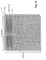
- Fig. 12 there is shown a representation of a data arrangement or organisation of the Sub-Band Buffer of Fig. 11.
- the Subband Buffer holds four (4) banks 1201 of thirty two (32) by thirty two (32) coefficients and each coefficient is represented by a sixteen (16) bit value.
- the Sub-Band RAM is a total of 64 Kbits and is organised as 1024 words of 64 bits, storing one coefficient from each subband at each memory location in parallel. That is, four coefficients, one from each subband at a current level, are represented each as sixteen (16) bits of a sixty four (64) bit word.
- the buffer 1101, and in particular each bank 1201 is filled in raster scan order from top to bottom as indicated by the zig-zag pattern 1202 shown in Fig. 12.
- the Subband RAM 1101 is read out in quadtree manner.
- the Entropy Encoder unit 609 comprises a Bitplane Converter module 1301 and Bitplane Buffer sub-module 1302 comprising sixteen (16) bitplane memories; a plurality of Bitplane Tree Builder units 1303 and corresponding Bitplane Tree buffer units 1304; a Bitplane Encoder 1305; and a plurality of intermediate buffers 1306 for intermediate storage of data use by the Bitplane Encoder 1305.
- the data stored in Sub-band RAM 1101 is read in quadtree order from the Subband Buffer module 607.
- the bitplane converter module 1301 splits up each bit plane's data and writes into each of 16 bitplane memories in the Bitplane Buffer submodule 1302.
- the data is also scanned by the plurality Bitplane Tree Builders which write processed bit plane tree structure information into corresponding Bitplane Tree buffers 1304.
- Data from each Bitplane Tree 1304 and the Bitplane Buffer 1302 is used by the Bitplane Encoder 1305 to perform a bit-stream generation which is output (via bus 613).
- the Bitplane Encoder 1305 is synchronised (controlled) by the control state machine module 604.
- the intermediate buffers 1306 comprise: a buffer for temporarily storing a List of Significant Coefficients (LSC); a buffer for temporarily storing a List of Insignificant Coefficients (LIC); and a buffer for temporarily storing an Old Insignificant Region (OIR) list which can also be implemented as two buffers as a first list of regions buffer and a second list of region buffer (not shown in Fig. 13).
- the Entropy Encoder Unit 609 includes a sign bit buffer (not shown in Fig. 13) which is connected to the output of the Bitplane Converter module 1301 and to an input to the Bit-plane Encoder 1305 which also encodes a sign bit into the bit-stream.
- An example of an Entropy Encoder unit is described in more detail later in this specification, under a heading "Entropy Encoder”.
- Entropy Encoding Unit which performs a quadtree bitplane encoding as described above, however other entropy encoders can be used without departing from the scope or spirit of the invention.
- a bitplane Arithmetic coder cart be used to encode the transform coefficients, or optionally a hybrid encoder performing part quadtree encoding and part Arithmetic coding of the DWT coefficients.
- the Partial Band Buffer Module 608 includes: RAM 1401 to store the LL subband data (i.e. ll_data 1006 generated by the Horizontal Filter Module 606 of Fig.6) for each level of decomposition; a Partial Band Buffer Address Generator submodule 1402 and a barrel shift register (barrel shifter) 1403.
- the Partial Band Buffer Address Generator 1402 supplies addresses to the Partial Band RAM 1401 as well as controlling writes into that RAM under the control of the Control State Machine module 604.
- the Partial Band Buffer holds LL subband data from each level of compression until enough samples are available to filter to a next level of decomposition. Once enough samples are available at any one level, the data is read out through the barrel shifter 1403 into the Vertical Filter module 605 to filter to a next level of decomposition.
- the RAM 1401 comprises three separate buffers, each one being one hundred (100) cells wide with each cell capable of storing a 16 bit value.
- a first buffer, of the three separate buffers is 305 rows (lines) deep, a second buffer is 149 rows deep and a third buffer is 71 rows deep to a total of 525 rows (lines).
- the Barrel Shift register 1403 allows single clock alignment of data to the desired row required by the Vertical Filter module 605. Predetermined memory locations need to be read from the Partial Band RAM 1401 to produce a single word for the Vertical Filter 605. If the required single word wraps across a 9-line boundary, two adjacent memory location need to be read. This will typically occur in 8 out of every 9 line sets (each set comprising nine lines). In this case data is latched inside the Barrel Shifter 1403 until both words are read and all required bits are available and properly aligned.
- Fig. 15 there is shown a representation of the data organisation of the partial band buffer 608.
- the Partial Band Buffer 608 is 100 coefficients wide and 525 coefficients high, plus an extra 6 of 100 coefficient wide rows (not shown in Fig 15) as described above.
- the Partial band buffer 608 is written to with data (coefficients) after at least one level DWT decomposition of a tile is performed.
- a tile of (2 J H + 7(2 J - 1)) x (2 W + 7) of the image reduces to tile of coefficient after one level of decomposition. That is a 617 x 71 pixel tile after a first level of decomposition reduces to a tile of 305x32 coefficients.
- the Partial band buffer 608 of the preferred embodiment is thus designed to accommodate at least width-wise three 32-coefficient wide tiles 1501 and a 4-coefficient wide block 1502.
- the 4-coefficient wide block 1502, at least for a first tile process, is filled with a mirror image of the first four columns of coefficients of a first 32-coefficient wide tile 1501 (hereinafter referred to as "padding" or "padded").
- Padding is usually performed to account for boundaries of an image where pixel data outside the image boundary is nonexistent.
- Other padding techniques are available to account for an image boundary. For example a simplest, but not necessarily the best, option is to pad the boundary of an image with zeros (0).
- the 4-coefficient wide block at each level is used as overlap for filtering the horizontal lines.
- the shaded area 1507 of Fig. 15 consisting of 305 x 71 coefficients for second level decomposition is required to generate a tile of 149 x 32 coefficients for third level decomposition.
- the coefficients in the shaded area 1507 are read out in scan line order, 71 to the line from left to right and top to bottom.
- Partial Band buffer 608 is filled to a desired amount (eg 71 columns) at a next (higher) level
- column addresses at a current level are incremented by sixty four (64) columns to the right, wrapping back to the first column as the addresses exceed the hundredth column. That is, for example processing of a next seventy one (71) columns of coefficients, at a current level, is commenced at the sixty fourth column 1508 of the buffer 608 and wrapping around to the first column of the buffer 608.
- Column sixty four (64) to column sixty eight (68) now provides a 4-coefficient wide block 1509 overlap necessary to process another seventy one (71) columns of data.
- results of the filter are written to a next higher level of the Partial band buffer 608 shown in Fig 15.
- a highest level has been filtered (eg "level 4" of Fig 15)
- a resulting LL subband coefficients are written to the Sub-Band Buffer 607 without further writing these coefficients into the Partial Band Buffer 608 and are encoded straight away, without further filtering.
- 9 x 16 144 bits are read at a time. These 9 words represent 9 vertical coefficients from a single column of the buffer. Because the line address is incremented by two between reading complete lines out of this buffer, it is necessary to pass the 144-bit data stream through a barrel shifter to align the data with the data bus into the Vertical Filter. It is also necessary to read 2 words in succession to get one 144-bit word, building up the two parts of the word by holding the required bits of the first word in registers while the required bits from the second access are fetched. Only when the alignment of the line address is a multiple of 9 will one fetch only be required. In order to be able to fetch 144-bits at a time, the memory must physically be 144 bits wide. Extra decoding is required (so that just 16 bits can be written at a time) in the form of word write enables to the memory array.
- the Control State Machine Module 604 is responsible for controlling the function of each module 601, 604-609 and for correctly routing data to each module in synchronism wit a modules function (ie at the right time).
- a "level" variable is set 1602 to one (1), which typically represents a first level of decomposition to be performed.
- a decision block 1603 is entered to determine if the current level of DWT decomposition is the first level. If decision block 1603 returns true (yes) then a first nine (9) lines of the image stored in DRAM 403 (Fig. 4) are filtered 1604 to produce a first line of sub-band data. Input data is retrieved from the external DRAM 403 for level 1. Otherwise the decision block 1603 returns false (no) causing the flow to proceed to block 1605 where data is retrieved from the internal Partial Band Buffer 608 and filtered (DWT decomposed to a next level).
- Enough data is retrieved from the Partial Band Buffer 608 to produce a line, of a tile, of DWT coefficients of a next level. These results are stored in the Partial Band Buffer 608 of a location for a corresponding level as previously described.
- a check 1606 is made to see if the subband buffer 607 is full. If this check 1606 returns false (no) the process flow is returned to decision block 1603 and continues as described above with reference to decision block 1603. If check block 1603 returns true (yes) a further decision (or check) block 1607 is entered and a check is made to see if the data is within an overlap region 200 for a level that is being filtered. If not, that is block 1607 returns false (no) then three subbands LH, HL and HH stored in the subband buffer 607 are encoded 1608.
- a decision block 1609 is entered and a check is made to determine if a current level of decomposition is a maximum level (that is level 4). If the current level is 4 decision block 1609 returns true (yes) a LL subband in the subband buffer 607 is also encoded 1610 and the flow process continues at decision block 1611. Further, at decision block 1609 if false (no) is returned the flow process continues at decision block 1611 without encoding the LL subband in the subband buffer 607.
- decision block 1607 Another entry to decision block 1611 is via decision block 1607, where decision block 1607 returns true (yes). That is, the data being processed is within an overlap region 201 or 200 of adjacent tiles. The check performed at decision block 1607 is used to prevent the encoding of the overlap region twice. The process flow proceeds to decision block 1611 when decision block 1607 returns true (yes).
- level two (2) partial band buffer is not ready to be filtered, that is, a complete set (ie. a tile at level two (2) comprising 71 by 361 coefficients) is not present in the partial band buffer 608, then false is returned by decision block 1611 and check (decision) block 1613 is entered.
- check block 1613 a check is made on whether at level three (3) of partial band buffer a complete set of 71 columns of (128 + 21) rows of coefficients are present. If so, then the level variable is set 1614 to three (3) and processing is resumed at decision block 1603 and continues through steps 1605 to 1613, as described above, with data retrieved from level three (3) of the partial band buffer 608.
- level three (3) partial band buffer 608 is not ready to be filtered, that is, a complete set (ie. a tile at level three (3) comprising 71 by 149 coefficients) is not present in the partial band buffer 608, then false (no) is returned by decision block 1613 and check (decision) block 1615 is entered.
- check block 1615 a check is made on whether at level four (4) of partial band buffer a complete set of 71 columns of (64 + 7) rows of coeffi-cients are present. If so, ten the level variable is set 1616 to four (4) and processing is resumed at decision block 1603 and continues through steps 1605 to 1615, as described above, with data retrieved from level four (4) of the partial band buffer 608.
- decision block 1615 If the level four (4) partial band buffer 608 is not ready to be filtered, ten false (no) is returned by decision block 1615 and check (decision) block 1617 is entered. At block 1617 a check is made to see if the entire image has been completely processed. If this is the case decision block 1617 returns true (yes) and the flow process terminates 1618. Otherwise, decision block 1617 returns false (no) and processing is resumed at block 1602, assigning the level variable one (1) and the processing is continued and described above with reference to steps 1602 to 1617 again with data retrieved from the external DRAM 403.
- the partial band buffer 608 is initially loaded with three tiles of coefficients in order to process a next level. For every subsequent tile to be generated at the next level only two additional tiles of input are necessary since the partial band buffer 608 already contains at least one tile from previously load data. In the present embodiment requires 71 columns of coefficients, in the partial band buffer, for a current level to allow filtering to a next level.
- Partial Band Buffer 608 can be implemented as three separated memory units one for each level of decomposition rather than implementing the buffer 608 as a single buffer memory as illustrated in Fig. 15. This option may require separate read and write address generators.
- the method of encoding a digital image can be practiced using a conventional general-purpose computer system 1700, such as that shown in Fig. 17 wherein the processes relating to Figs. 2, 3 and 5, for example, can be implemented as software, such as an application program executing within the computer system 1700.
- the steps of the method of encoding a digital image are effected by instructions in the software that are carried out by the computer.
- the software can be divided into two separate parts; one part for carrying out the encoding methods, and another part to manage the user interface between the latter and the user.
- the software can be stored in a computer readable medium, including the storage devices described below, for example.
- the software is loaded into the computer from the computer readable medium, and then executed by the computer.
- a computer readable medium having such software or computer program recorded on it is a computer program product.
- the use of the computer program product in the computer preferably effects an apparatus for encoding a digital image in accordance with the embodiments of the invention.
- the computer system 1700 comprises a computer module 1701, input devices such as a keyboard 1702 and mouse 1703, output devices including a printer 1715 and a display device 1714.
- a Modulator-Demodulator (Modem) transceiver device 1716 is used by the computer module 1701 for communicating to and from a communications network 1720, for example connectable via a telephone line 1721 or other functional medium.
- the modem 1716 can be used to obtain access to the Internet, and other network systems, such as a Local Area Network (LAN) or a Wide Area Network (WAN).
- LAN Local Area Network
- WAN Wide Area Network
- the computer module 1701 typically includes at least one processor unit 1705, a memory unit 1706, for example formed from semiconductor random access memory (RAM) and read only memory (ROM), input/output (I/O) interfaces including a video interface 1707, and an I/O interface 1713 for the keyboard 1702 and mouse 1703 and optionally a joystick (not illustrated), and an interface 1708 for the modem 1716.
- a storage device 1709 is provided and typically includes a hard disk drive 1710 and a floppy disk drive 1711. A magnetic tape drive (not illustrated) may also be used.
- a CD-ROM drive 1712 is typically provided as a non-volatile source of data.
- the components 1705 to 1713 of the computer module 1701 typically communicate via an interconnected bus 1704 and in a manner which results in a conventional mode of operation of the computer system 1700 known to those in the relevant art.
- Examples of computers on which the embodiments can be practised include IBM-PC's and compatibles, Sun Sparestations or alike computer systems evolved therefrom.
- the application program of the preferred embodiment is resident on the hard disk drive 1710 and read and controlled in its execution by the processor 1705. Intermediate storage of the program and any data fetched from the network 1720 may be accomplished using the semiconductor memory 1706, possibly in concert with the hard disk drive 1710. In some instances, the application program can be supplied to the user encoded on a CD-ROM or floppy disk and read via the corresponding drive 1712 or 1711, or alternatively may be read by the user from the network 1720 via the modem device 1716.
- the software can also be loaded into the computer system 1700 from other computer readable medium including magnetic tape, a ROM or integrated circuit, a magneto-optical disk, a radio or infra-red transmission channel between the computer module 1701 and another device, a computer readable card such as a PCMCIA card, and the Internet and Intranets including email transmissions and information recorded on websites and the like.
- computer readable medium including magnetic tape, a ROM or integrated circuit, a magneto-optical disk, a radio or infra-red transmission channel between the computer module 1701 and another device, a computer readable card such as a PCMCIA card, and the Internet and Intranets including email transmissions and information recorded on websites and the like.
- the method of encoding a digital image can alternatively preferably be implemented in dedicated hardware such as one or more integrated circuits performing the functions or sub functions of encoding a digital image.
- dedicated hardware may include graphic processors, digital signal processors, or one or more microprocessors and associated memories.
- a method for producing a coded representation of coefficients of a transform of an image.
- the method relates to embedded block coding using quadtrees.
- an original image 1801 is transformed utilizing a Discrete Wavelet Transform (DWT) into four sub-images 1803-1806.
- the sub-images or subbands are normally denoted LL1, HL1, LH1 and HH1.
- the one suffix on the subband names indicates level 1.
- the LL1 subband is a low pass decimated version of the original image.
- the wavelet transform utilized can vary and can include, for example, Haar basis functions, Daubechies basis functions etc.
- the LL1 subband is then in turn utilized and a second Discrete Wavelet Transform is applied as shown in Figure 19 giving subbands LL2 (1908), HL2 (1909), LH2 (1910), HH2 (1911). This process is continued for example as illustrated in Figure 20 wherein the LL4 subband is illustrated. Obviously, further levels of decomposition can be provided depending on the size of the input image.
- the lowest frequency subband is referred to as the DC subband. In the case of Figure 20, the DC subband is the LL4 subband.
- Each single level DWT can, in turn, be inverted to obtain the original image.
- a J-level DWT can be inverted as a series of J-single level inverse DWT's.
- the DC subband is coded first. Then, the remaining subbands are coded in order of decreasing level. That is for a 4 level DWT, the subbands at level 4 are coded after the DC subband (LL4). That is the HL4, LH4 and HH4 subbands.
- the subbands at level 3 (HL3, LH3, and HH3) are then coded, followed by those at level 2 (HL2, LH2 and HH2) and then level 1 (HL1, LH1 and HH1).
- the encoded subbands normally contain the "detail" information in an image. After quantisation of the subbands, they often consist of a sparse array of values and substantial compression can be achieved by efficient encoding of their sparse matrix form.
- the subbands are preferably tiles 2110, 2120, 2130, 2140 and 2150 with 32x32 blocks of coefficients beginning from the top left-hand corner.
- the nomenclature 32x32 refers to 32 rows by 32 columns respectively.
- bit n the decimal number 9 is represented as 00001001.
- bit 3 is equal to 1
- bits 2, 1, and 0 are equal to 0, 0, and 1, respectively.
- a transform of an image may be represented as a matrix having coefficients arranged in rows and columns, with each coefficient represented by a bit sequence.
- the matrix may be regarded as having three dimensions; one dimension in the row direction; a second dimension in the column direction and a third dimension in the bit sequence direction.
- a plane in this three-dimensional space that passes through each bit sequence at the same bitnumber is referred to as a "bitplane” or "bit plane”.
- bit plane number n refers to that bit plane that passes through bit number n .
- the transform coefficients are assumed hereinafter to be represented in a fixed point unsigned binary integer format, with an additional single sign bit.
- 16 bits is used. That is, the decimal numbers -9 and 9 are represented with the same bit sequence, namely 1001, with the former having a sign bit equal to 1 to indicate a negative value, and the latter having a sign bit equal to 0 to indicate a positive value.
- the coefficients are implicitly already quantized to the nearest integer value, although this is not necessary. Further, for the purpose of compression, any information contained in fractional bits is normally ignored.
- a region of an image frame includes a set of contiguous image coefficients.
- the term coefficient is used hereinafter interchangeably with pixel, however, as will be well understood by a person skilled in the art, the former is typically used to refer to pixels in a transform domain (eg., a DWT domain).
- These sets or regions T are defined as having transform image coefficients ⁇ c i,j ⁇ where ( i,j ) is a coefficient coordinate, fixed point unsigned binary integer format, with an additional single sign bit. We typically use 16 bits.
- a set or the region T of pixels at a current bit plane is said to be insignificant if the msb number of each coefficient in the region is less than the value of the current bit plane.
- a mathematical definition is given in Equation (1).
- a set or region T of pixels is said to be insignificant with respect to (or at) bit plane n if,
- T is a square region and the set ⁇ T m ⁇ is the set consisting of the four quadrants of T .
- the proposed method encodes a set of coefficients in an embedded manner using quadtrees.
- embedded is taken to mean that every bit in a higher bit plane is coded before any bit in a lower bit plane. For example, every bit is coded in bit plane 7 before any bit in bit plane 6. In turn, all bits in bit plane 6 are coded before any bit plane 5 and so on.
- a preferred embodiment of the proposed method is implemented utilizing the following pseudo-code.
- the proposed method preferably encodes a square block of coefficients, with a block size that is a power of 2 (typically 32x32 coefficients). Further, the proposed method utilizes a quadtree partition: that is each set or region is partitioned into its 4 quadrants: thus maintaining at all times square regions with a dimension equal to a power of two.
- the proposed method during commencement, initializes three lists: a list of insignificant regions (LIR); a list of insignificant coefficients (LIC); and a list of significant coefficients (LSC). When single coefficients are removed from the list of insignificant sets (LIR), they are added to either the list of insignificant coefficients (LIC) or to the list of significant coefficients (LSC), depending on the significance of the coefficient.
- the proposed method is initialized as follows.
- the LIC and LSC are initialized to be empty.
- the LIR is set to contain the four quadrants of the input block.
- the method commences by finding and coding n max , which is the largest bit plane that contains a 1 bit for all the coefficients in the set.
- the proposed method then proceeds as follows:
- LIR' is the coded representation undertaken in step 3
- LIC' is the coded representation undertaken in step 2
- LSC' is the coded representation undertaken in step 4.
- LIR' is the coded representation undertaken in step 3
- LIC' is the coded representation undertaken in step 2
- LSC' is the coded representation undertaken in step 4.
- both LIC and LSC are empty and thus the output bitstream for the first iteration takes the form LIR'.
- a simple Huffman code (or better a Golomb code) may be used to code groups of bits (for example groups of 4 bits) when coding the LIC and LSC.
- groups of bits for example groups of 4 bits
- a 15-level Huffman code may be used to indicate the significance pattern of each of the 4 quadrants (one quadrant must be significant, hence the significance pattern can be one of 15 (and not 16) different patterns.
- Other forms of entropy encoding can be used, such as binary arithmetric coding to exploit any remaining redundancy.
- the proposed method at step 3 may perform the following substep. Immediately code and output the significance of each coefficient of the 2x2 block, output the corresponding sign bit(s) if they are significant; and then add the coefficients to the end of the LSC or the LIC as appropriate. In the latter substep, the significant coefficients are added to the LSC list whereas the insignificant coefficients are added to the LIC list.
- the proposed method encodes a 32x32 block of data coefficients.
- the following example of a 4x4 block of coefficients is encoded in accordance with the proposed method.
- the above block consists of four quadrants A,B,C and D.
- the symbol A designates the top-left (2x2) quadrant of the block, B the top right, C the bottom left, and D the bottom right quadrant respectively.
- the symbols A1 denote the top left pixel of A, A2 the top right, A3 the bottom left, A4 the bottom right pixels respectively.
- B1 denotes the top left pixel of B and so on for the rest of the pixels.
- n max is first determined, which in this case is 4. That is, the most significant bit of each coefficient is in bit plane 4 or less. Note, the numbering of the bit planes commences from 0.
- bit planes are iteratively coded.
- bit plane 4 (and higher) have been coded. That is a decoder can reconstruct bit plane 4 (and higher) by reading in the bits from the coded bit stream.
- the decoding method is the same except that the significance decisions are determined by reading from the bit stream (this is why the significance decision is written to the bit stream). The other coefficient bits are simply read in as is. Note that the decoder execution path is identical to the encoder, so that the decoder knows the meaning of each new bit that it reads.
- the method is preferably utilized in encoding 32x32 blocks of coefficients.
- the original quadrants A,B,C,D each consist of 16x16 coefficients and the regions A1,A2,...D4 each consist of 8x8 coefficients. It will be thus evident in encoding a 32x32 block, the block is partitioned in accordance with quadtree method five times, whereas in the example given the 4x4 block is partitioned only twice.
- the decoding process simply mimics the encoding process to reconstruct the pixels from the coded representation.
- the coefficient encoder 2200 is designed to provide a continual flow of output encoded data 2204 taking in corresponding data 2202.
- the encoder 2200 includes the following logic portions; a bit plane converter 2206; bit plane tree builders 2208-0 to 2208-15; and a bit plane encoder 2210.
- the encoder 2200 also includes a memory 2214 for storing the 32x32 coefficients in bit planes; a memory 2216 for storing the sign bits of the coefficients; and memories 2218-15 to 2218-0 for storing bit plane trees 0 to 15.
- the encoder 2200 further includes a memory 2226 for storing a first list of regions; a FIFO memory 2228 for storing a second list of regions; a memory 2222 for storing a list of LSC values; and a memory 2224 for storing a list of LIC values.
- the encoder 2200 operates in the following manner. Initially, the 32x32 input coefficient data are stored in the memory 2212 in raster order.
- the bit plane converter 2206 reads the input coefficient data and converts the data into 16 bit planes from bitplane 0 through to bitplane 15, which are subsequently stored in memory 2214.
- the bit plane converter 2206 also determines the sign bit of the coefficients of the 32x32 block, which sign bits are stored in memory 2216.
- the bit plane tree builders 2208-0 to 2208-15 each read the 32x32 coefficient data and construct a quadtree structure having nodes corresponding to regions and 1x1 pixels.
- the nodes are set to 1 if the region or pixel corresponding to that node is significant for that bitplane. If the significant bit for the region or pixel corresponding to that node is greater than or less than the bitplane then the node is set to zero.
- the tree 2300 includes nodes representing each quadtree partition of the block down to the 1x1-pixel level. In this tree, the whole 32x32 block is represented by the symbol O.
- the 16x16 top left quadrant is represented by node A
- the 16x16 top right quadrant is represented by B
- the 16x16 bottom left quadrant is represented by node C
- the 16x16 bottom right quadrant is represented by node D.
- the nodes A1,A2,A3,and A4 represent the top left, top right, bottom left, and bottom right 8x8 quadtree partitions of the quadrant A respectively.
- the nodes A11, A12,A13,and A14 represent the top left, top right, bottom left, and bottom right 4x4 quadtree partitions of the quadrant A1 respectively.
- the nodes A111, A112,A113,and A114 represent the top left, top right, bottom left, and bottom right 2x2 quadtree partitions of the quadrant A11 respectively.
- the nodes A1111, A1112, A1113, and A1114 represent the top left, top right, bottom left, and bottom right 1x1 quadtree partitions (i.e. pixels) of the quadrant A111 respectively.
- the remaining parts of the tree (not shown) is represented in a similar manner down to each 1x1 quadrant of the 32x32 block.
- the bit plane treebuilder 2208-n builds such a tree from bottom up for bitplane n by reading the coefficients in quadrant order (e.g. A1111,A1112,A1113, and A1114).
- the tree builder sets the nodes of the tree to 1 if the region or pixel corresponding to that node is significant for that bitplane. If the significant bit for the region or pixel corresponding to that node is greater than or less than the bitplane then the node is set to zero by the tree builder.
- the bit plane tree builder then outputs the significance information for each node in the following format
- the output from each of the bitplane tree builders 2208-0 to 2208-15 are then stored in respective bitplane tree memories 2218-0 to 2218-15.
- the bit plane encoder 2210 reads each of the bit plane tree memories in turn, commencing with bit plane tree memory 2218-15.
- the bit plane encoder 2210 starts processing by reading in turn the four significance bits A,B,C, and D stored in the bit plane memory 2218-15 corresponding to the nodes A, B, C, and D.
- the bit plane encoder stores a list of these nodes ⁇ A,B,C,D ⁇ in a first list of regions in memory 2226.
- the bit plane encoder 2210 then proceeds with the following operations:
- the bit plane encoder repeats this operation for the remaining bit plane trees in turn.
- the first list of regions at the start of the operation on the current bitplane free contains those regions remaining from the previous operation on the previous bitplane tree. These outputs bits correspond to the LIR' portion of the output stream.
- the bitplane encoder After completion of a current operation for a current bitplane tree, the bitplane encoder then encodes and outputs the LIC and LSC bits.
- the bit plane encoder encodes the LIC bits by reading the LIC list for the index to the first pixel on the list, and using the current bit plane number selects the bit needed from the bit plane memory 2214. If the selected bit is a binary zero, then the encoder outputs a zero. If the selected bit is a binary one, then the encoder outputs a binary one together with the sign bit of the pixel from memory 2216. The encoder then removes the index from the LIC list and adds it to the LSC list. Preferably, once an index is removed from the list, the remaining indices are reorganized. The encoding is completed once the LIC list is traversed.
- the bit plane encoder encodes the LSC bits by reading the LSC list for the index to the first pixel on the list, and using the current bit plane number to select the bit needed from the bit plane memory 2214. The selected bit is then outputted.
- the bit plane encoder also includes a counter for storing a length value, which is indicative of the number of pixels in the LSC list to be read. At the end of the LSC encoding the value is updated so that the new elements from LIR and LIC can be added.
- the encoding and decoding processes of the proposed method are preferably practiced using a conventional general-purpose computer, such as the one shown in Fig. 24, wherein the processes may be implemented as software executing on the computer.
- the steps of the coding and/or decoding methods are effected by instructions in the software that are carried out by the computer.
- the software may be divided into two separate parts; one part for carrying out the encoding and/or decoding methods; and another part to manage the user interface between the latter and the user.
- the software may be stored in a computer readable medium, including the storage devices described below, for example.
- the software is loaded into the computer from the computer readable medium, and then executed by the computer.
- a computer readable medium having such software or computer program recorded on it is a computer program product.
- the use of the computer program product in the computer preferably effects an advantageous apparatus for encoding digital images and decoding coded representations of digital images in accordance with the embodiments of the invention.
- the computer system 2400 consists of the computer 2401, a video display 2414, and input devices 2402, 2403.
- the computer system 2400 can have any of a number of other output devices including line printers, laser printers, plotters, and other reproduction devices connected to the computer 2401.
- the computer system 2400 can be connected to one or more other computers via a communication interface 2408 using an appropriate communication channel 2421 such as a modem communications path, a computer network, or the like.
- the computer network may include a local area network (LAN), a wide area network (WAN), an Intranet, and/or the Internet
- the computer 2401 itself consists of a central processing unit(s) (simply referred to as a processor hereinafter) 2405, a memory 2406 which may include random access memory (RAM) and read-only memory (ROM), input/output (IO) interfaces 2408, 2413, a video interface 2407, and one or more storage devices generally represented by a block 2409 in Fig. 24.
- the storage device(s) 2409 can consist of one or more of the following: a floppy disc, a hard disc drive, a magneto-optical disc drive, CD-ROM, magnetic tape or any other of a number of non-volatile storage devices well known to those skilled in the art.
- Each of the components 2405 to 2413 is typically connected to one or more of the other devices via a bus 2404 that in turn can consist of data, address, and control buses.
- the video interface 2407 is connected to the video display 2414 and provides video signals from the computer 2401 for display on the video display 2414.
- User input to operate the computer 2401 can be provided by one or more input devices 2402-3.
- an operator can use the keyboard 2402 and/or a pointing device such as the mouse 2403 to provide input to the computer 2401.
- the system 2400 is simply provided for illustrative purposes and other configurations can be employed.
- Exemplary computers on which the embodiment can be practiced include IBM-PC/ATs or compatibles, one of the Macintosh (TM) family of PCs, Sun Sparcstation (TM), or the like.
- TM Macintosh
- TM Sun Sparcstation
- the foregoing are merely exemplary of the types of computers with which the embodiments may be practiced.
- the processes of the embodiments, described hereinafter are resident as software or a program recorded on a hard disk drive (generally depicted as block 2410 in Fig. 24) as the computer readable medium, and read and controlled using the processor 2405.
- Intermediate storage of the program and pixel data and any data fetched from the network may be accomplished using the semiconductor memory 2406, possibly in concert with the hard disk drive 2410.
- the program may be supplied to the user encoded on a CD-ROM or a floppy disk (both generally depicted by block 2411), or alternatively could be read by the user from the network via a modem device connected to the computer, for example.
- the software can also be loaded into the computer system 2400 from other computer readable medium including magnetic tape, a ROM or integrated circuit, a magneto-optical disk, a radio or infra-red transmission channel between the computer and another device, a computer readable card such as a PCMCIA card, and the Internet and Intranets including email transmissions and information recorded on websites and the like.
- the foregoing are merely exemplary of relevant computer readable mediums. Other computer readable mediums maybe practiced.
- the encoded image can first be fully entropy-decoded, and then a process applied to the now decoded image, said process being substantially the reverse of the encoding method described.
Abstract
Description
- The present invention relates to the field of digital image compression, and in particular, to a method and apparatus for performing a wavelet decomposition of an image.
- The field of digital data compression and in particular digital image compression has attracted a great interest for some time. Most recently, compression schemes based on a Discrete Wavelet Transform (DWT) have become increasingly popular because the DWT offers a non-redundant heirachical decomposition of an image, and resultant compression of the image provides favourable rate-distortion statistics.
- Typically, the discrete wavelet transform (DWT) of an image is performed using a series of one-dimensional DWT's. A one dimensional DWT of a signal (ie an image row) is performed by lowpass and highpass filtering the signal, and decimating each filtered signal by 2. Decimation by 2 means that only every second sample of the filtering proc-esses is calculated and retained. When performing a convolution (filtering) the filter is moved along by two samples at a time, instead of the usual one sample. In this way, for a signal of N samples, there are N DWT samples: substantially N/2 lowpass samples and substantially N/2 highpass samples.
- This is typically performed by buffering an entire image in Computer Memory such as Random Access Memory (RAM), performing the DWT on the buffered image, and then encoding the transformed image. Unfortunately, this approach requires a large amount of memory, particularly for images of 2000 pixels x 2000 pixels or more, and a considerable memory bandwidth is required if sufficient processing speed is to be attained.
- It is a concern of the present invention to substantially overcome, or at least ameliorate, one or more disadvantages of existing arrangements.
- According to a first aspect of the invention there is provided a method of encoding an digital image comprising a plurality of pixels, said image being able to be transformed by a discrete wavelet transform (DWT) to a predetermined level of decomposition, and capable of being encoded on a block by block basis, each block having a specified block size in number of coefficients, in a first and second dimension, the method comprising the steps of:
- a) dividing the image into a plurality of tiles, each tile having firstly, substantially a minimum number of pixels required to produce the number of coefficients in the first dimension of said block at said predetermined level of DWT decomposition, and secondly, by less than a minimum number of pixels required to produce the number of coefficients in the second dimension of said block at said predetermined level of DWT decomposition;
- b) selecting a current tile;
- c) decomposing said current tile using the DWT to at least one level of decomposition to form a plurality of subbands including a LL, LH, HL and HH subband;
- d) accumulating coefficients in each subband of the LH, HL and HH subbands to form blocks of said specified size, and encoding each said block to a bit stream;
- e) accumulating LL subband coefficients and repeating steps b) to e) until a predetermined number of coefficients of the LL subband have been accumulated;
- f) assigning as a current tile said predetermined number of accumulated LL sub-band coefficients;
- g) repeating steps c) to g) until the predetermined level of decomposition is reached; and
- h) encoding the LL subband into the bit stream.
-
- According to a second aspect of the invention there is provided a method of encoding an digital image comprising a plurality of pixels, said image being able to be transformed by a discrete wavelet transform (DWT) to a predetermined level of decomposition and capable of being encoded on a block by block basis, each block having a specified block size in number of coefficients, in a first and second dimension, the method comprising the steps of:
- a) dividing the image into a plurality of tiles, each tile having firstly substantially a minimum number of pixels required to produce the number of coefficients in the first dimension of said block at said predetermined level of DWT decomposition, and secondly, less than a minimum number of pixels required to produce the number of coefficients in the second dimension of said block at said predetermined level of DWT decomposition;
- b) selecting a tile of the image as a current tile;
- c) decomposing said current tile using the DWT to a provide a plurality of coefficients in LL, LH, HL and HH subbands;
- d) encoding coefficients of the LH, HL, HH subbands of a current level into a bit-stream;
- e) determining if said current level is the predetermined level:
- ea) encoding the coefficients of the LL subband into the bitstream, if the current level is the predetermined level; and repeating steps b) to e); and
- eb) storing coefficients not previously encoded of the LL subband if the current level is not the predetermined level;
- f) determining if the number of said stored coefficients of the LL subband
at the current level is at least a predetermined number:
- fa) assigning said predetermined number of LL coefficients as a current tile, if the number of stored LL coefficients is at least said predetermined number; and repeating steps c) to f); and
- fb) repeating steps b) to f) if the number of stored LL coefficients is less than said predetermined number.
-
- According to a third aspect of the invention there is provided an apparatus for encoding an image, said image being capable of being transformed by a discrete wavelet transform (DWT) to a predetermined level of decomposition and capable of being encoded on a block by block basis, each block having a specified block size in number of coefficients, in a first and second dimension, the apparatus comprising:
- a) means for dividing the image into a plurality of tiles, each tile having firstly, substantially a minimum number of pixels required to produce the number of coefficients in the first dimension of said block at said predetermined level of DWT decomposition, and secondly, less than a minimum number of pixels required to produce the number of coefficients in the second dimension of said block at said predetermined level of DWT decomposition;
- b) selecting means for selecting a current tile;
- c) decomposing means for decomposing said current tile using the DWT to at least one level of decomposition to form a plurality of subbands including a LL, LH, HL and HH subband;
- d) means for accumulating a predetermined number of coefficients of the LL sub-band coefficients;
- e) means for assigning, as a current tile, said predetermined number of accumulated LL subband coefficients;
- f) means for feeding back the current tile to the decomposing means for decomposing the current tile to a further level of decomposition;
- g) means for accumulating coefficients in each subband of the LH, HL and HH subbands to form blocks of said specified size, and accumulating at least one block of said specified size in the LL subband at said predetermined level; and
- h) encoding means for encoding each said block to a bit stream.
-
- According to a fourth aspect of the invention there is provided an apparatus for encoding an image, said image being capable of being transformed by a discrete wavelet transform (DWT) to a predetermined level of decomposition, and capable of being encoded on a block by block basis, each block having a specified block size in number of coefficients, in a first and second dimension, the apparatus comprising:
- storage means for storing at least a portion of said image, the portion of the image having firstly, substantially a minimum number of pixels required to produce the number of coefficients in the first dimension of said block at said predetermined level of DWT decomposition, and secondly, less than a minimum number of pixels required to produce the number of coefficients in the second dimension of said block at said predetermined level of DWT decomposition;
- a first and second filtering means for applying a linear transform to a first and second dimension of said image portion respectively to provided a LL, LH, HL and HH subband, each subband comprising at least one coefficient;
- a partial band storage means for accumulating a predetermined number of coefficients of the LL subband. and using the accumulated LL coefficient as an image portion for refiltering by the first and second filtering means to achieve a next level decomposition;
- a subband storage means for accumulating said blocks of specified size for each level in the LH, HL and HH subbands, and accumulating said blocks of specified size in the LL subband at said predetermined level of decomposition; and
- encoder means for encoding each accumulated block into a bit stream.
-
- According to a fifth aspect of the invention there is provided a computer readable memory medium for storing a program for apparatus which encodes an digital image comprising a plurality of pixels, said image being able to be transformed by a discrete wavelet transform (DWT) to a predetermined level of decomposition and capable of being encoded on a block by block basis, each block having a specified block size in number of coefficients, in a first and second dimension, said program comprising:
- a) code for a dividing step for dividing the image into a plurality of tiles, each tile having firstly, substantially a minimum number of pixels required to produce the number of coefficients in the first dimension of said block at said predetermined level of DWT decomposition, and secondly, less than a minimum number of pixels required to produce the number of coefficients in the second dimension of said block at said predetermined level of DWT decomposition;
- b) code for a selecting step for selecting a current tile;
- c) code for a decomposing step for decomposing said current tile using the DWT to at least one level of decomposition to form a plurality of subbands including an LL, LH, HL and HH subband;
- d) code for an accumulating step for accumulating coefficients in each subband of the LH, HL and HH subbands to form blocks of said specified size and for encoding each said block to a bit stream;
- e) code for an accumulating step for accumulating LL subband coefficients, and for repeating steps b) to e) until a predetermined number of coefficients of the LL subband have been accumulated;
- f) code for an assigning step for assigning as a current tile said predetermined number of accumulated LL subband coefficients;
- g) code for repeating steps c) to g) until the predetermined level of decomposition is reached; and
- h) code for an encoding step for encoding the LL subband into the bit stream.
-
- According to a sixth aspect of the invention there is provided a computer readable memory medium for storing a program for apparatus which encodes an digital image comprising a plurality of pixels, said image being able to be transformed by a discrete wavelet transform (DWT) to a predetermined level of decomposition and capable of being encoded on a block by block basis, each block having a specifyied block size in number of coefficients, in a first and second dimension, said program comprising:
- a) code for a dividing step for dividing the image into a plurality of tiles, each tile having firstly, substantially a minimum number of pixels required to produce the number of coefficients in the first dimension of said block at said predetermined level of DWT decomposition, and secondly, less than a minimum number of pixels required to produce the number of coefficients in the second dimension of said block at said predetermined level of DWT decomposition;
- b) code for a selecting step for selecting a tile of the image as a current tile;
- c) code for a decomposing step for decomposing said current tile using the DWT filter to provide a plurality of coefficients in LL, LH, HL and HH subbands;
- d) code for an encoding step for encoding coefficients of the LH, HL, HH subbands of a current level into a bitstream;
- e) code for a determining step for determining if said current level is the
predetermined level:
- ea) code for an encoding step for encoding the coefficients of the LL subband into the bitstream, if the current level is the predetermined level; and repeating steps b) to e); and
- eb) code for a storing step for storing coefficients not previously encoded of the LL subband if the current level is not the predetermined level;
- f) code for a determining step for determining if the number of said stored
coefficients of the LL subband at the current level is at least a predetermined
number:
- fa) code for an assigning step for assigning said predetermined number of LL coefficients as a current tile, if the number of stored LL coefficients is at least said predetermined number, and repeating steps c) to f); and
- fb) code for a repeating step for repeating steps b) to f) if the number of stored LL coefficients is less than said predetermined number.
-
- According to a seventh aspect of the invention there is provided a method of encoding an digital image comprising a plurality of pixels, said image being able to be transformed by a discrete wavelet transform (DWT) to a predetermined number of levels of decomposition being at least two levels, and further capable of being encoded on a block by block basis, each block having a specified block size in number of coefficients, in a first and second dimension, the method comprising the steps of:
- a) dividing the image into a plurality of tiles, each tile having firstly, substantially a minimum number of pixels required to produce the number of coefficients in the first dimension of said block at said predetermined level of DWT decomposition, and secondly, less than a minimum number of pixels required to produce the number of coefficients in the second dimension of said block at said predetermined level of DWT decomposition;
- b) selecting a current tile;
- c) decomposing said current tile using the DWT to at least one level of decomposition to form a plurality of subbands including LL, LH, HL and HH subbands;
- d) accumulating coefficients in each subband of the LH, HL and HH subbands to form blocks of said specified size and encoding each said block to a bit stream;
- e) accumulating LL subband coefficients and repeating steps b) to e) until a predetermined number of coefficients of the LL subband have been accumulated;
- f) assigning as a current tile said predetermined number of accumulated LL sub-band coefficients;
- g) repeating steps c) to g) until the predetermined level of decomposition is reached; and
- h) encoding the LL subband into the bit stream.
-
- Notwithstanding any other forms which may fall within the scope of the present invention, preferred forms of the invention will now be described, by way of example only, with reference to the accompanying drawings in which:
- Fig. 1 illustrates various subbands of a four level discrete wavelet transform of an image;
- Fig. 2 represents a horizontal tiling of a image as a variation on a preferred embodiment of the present invention;
- Fig. 3 represents a vertical tiling of a image in accordance with the preferred embodiment of the present invention;
- Fig. 4 illustrates the encoder of the preferred embodiment of the present invention;
- Fig. 5 shows the tiling of Fig. 3 and a preferred tile scan order;
- Fig. 6 shows the compression engine of Fig. 4 in more detail;
- Fig. 7 illustrates a reorder buffer in accordance with the preferred embodiment of the present invention;
- Fig. 8 represents a fill order of the reorder buffer of Fig 7;
- Fig. 9 illustrates a vertical filter hardware arrangement in accordance with the pre-ferred embodiment of the present invention;
- Fig. 10 illustrates a horizontal filter hardware arrangement in accordance with the preferred embodiment of the present invention;
- Fig. 11 illustrates a subband buffer hardware arrangement in accordance with the preferred embodiment of the present invention;
- Fig. 12 represents a fill and scan order of the subband buffer of Fig 11;
- Fig. 13 illustrates a control state machine hardware arrangement in accordance with the preferred embodiment of the present invention;
- Fig. 14 illustrates a partial band buffer hardware arrangement in accordance with the preferred embodiment of the present invention;
- Fig. 15 represents a fill and scan order of the partial band buffer of Fig 14;
- Fig. 16 is a block diagram representing a functionality of the control state machine of Fig. 13; and
- Fig. 17 is a schematic block diagram of a general purpose computer upon which the preferred embodiment of the present invention can be practiced.
- Fig. 18 illustrates an original image, and a DWT transformation thereof;
- Fig. 19 illustrates a second level DWT transformation of the original image of Fig. 18;
- Fig. 20 illustrates a four level DWT transformation of the original of Fig. 18;
- Fig. 21 illustrates the tiling of the subbands into 32x32 blocks;
- Fig. 22 illustrates an encoder embodiment;
- Fig. 23 illustrates a portion of a tree constructed by a bitplane tree builder of Fig. 22; and
- Fig 24 illustrates a general-purpose computer for implementing the described encoding method.
-
- Where reference is made in any one or more of the accompanying drawings to steps and/or features, which have the same reference numerals, those steps and/or features have for the purposes of this description the same function(s) or operation(s), unless the contrary intention appears.
- Referring to Fig. 1 there is shown a discrete wavelet decomposition of an image to 4 levels. At a highest level,
level 4, there is a Low-Low (LL) frequency subband (or DC subband) and a High-Low (HL4) frequency subband, a Low-High (LH4) frequency sub-band and a High-High (HH4) frequency subband. At a next level down there is a High-Low (HL3) frequency subband, a Low-High (LH3) frequency subband and a High-High (HH3) frequency subband for the present level. At the lowest level there is High-Low (HL1) frequency subband, a Low-High (LH1) frequency subband and a High-High (HH1) frequency subband. - Each level is generated by an application of a (single-level) discrete wavelet transform (DWT). Thus an application of the DWT to an image will generate a DC subband for a first level and three higher frequency subbands HL1, LH1 and HH1. The DWT is then applied to the DC (or LL) subband of first level to generate a DC subband for a second level and three higher frequency subbands HL2, LH2 and HH2. In turn, a further application of the DWT to the DC subband of the second level will generate a DC subband of a third level and three higher frequency subbands HL3, LH3 and HH3 and so on to a desired level of decomposition. Consequently, a four level decomposition described above requires four applications of the (single-level) DWT, a first application to the image and subsequent applications to the resultant Low-Low frequency subbands in a recursive manner as described above.
- The preferred embodiment of the present invention achieves a predetermined level of decomposition, in a memory efficient and low memory bandwidth (bytes per pixel) implementation. Further the implementation of the preferred embodiment is substantially independent of a size of the image to be decom-posed (for images typically greater than 1K pixel by 1K pixels). That is, a discrete wavelet decomposition of an image at a predetermined level is provided by memory buffers with total memory capacity less than that required to buffer the entire image and substantially independent of a width or height of the image.
- The implementation according to the preferred embodiment of the present invention achieves efficient memory buffering and low memory bandwidth by fixing the number of maximum levels of DWT decomposition, dividing an image to be decomposed into a plurality of tiles and requiring that a first dimension of each tile be substantially a minimum number of pixels required to produced a predetermined size DC block in a corresponding (first) dimension of the DC block at the maximum level of a DWT decomposition. Further, a second dimension of each tile is less than the minimum number of pixels required to produced a corresponding (second) dimension of the predetermined size DC block. Preferably, the second dimension of each tile has a minimum length, measured in pixels, that is required to produce a (fraction) sub-multiple of a corresponding dimension of the predetermined size DC block at the maximum level.
- For example, using a
Daubechies 9/7 DWT filter (i.e. a 9 tap lowpass and 7 tap highpass), and entropy coding DWT blocks (arrays) of 32 coefficients x 32 coefficients (height x width), at each level to a maximum of 4 levels of DWT decomposition would require, according to the preferred embodiment, a sub-division of an image into a plurality of overlapping tiles, each tile being 617 pixel in a first dimension (e.g. height of a tile) and 71 pixels in a second dimension (e.g. width of a tile). Each tile is DWT decomposed to 4 levels, with intermediate buffering of the Low-Low frequency portions at each iteration of the decomposition, to produce a predetermined number of DC coefficients. After processing approximately nine (9) such tile, a 32 x 32 block of DC coefficient is recovered and entropy coded. Through each of the iteration, 32x32 blocks of higher frequency coefficients (eg HL, LH and HH at each level) are also entropy coded. - The preferred embodiment will be described, hereinafter, predominately with reference to a four level DWT decomposition of an image using a
Daubechies 9/7 DWT filter and subsequent entropy coding of 32x32 blocks of DWT coefficients, however the invention is not limited thereto. A different predetermined maximum number of decomposition levels, a different filter and/or a different block size of accumulated coefficients before entropy coding the block can be used without departing from the scope and spirit of the invention. For example a 5 level DWT decomposition can be performed and/or 64x64 blocks of DWT coefficients can be accumulated before entropy coding a block. Further, a multitude of wavelet filters can be used including "HAAR" filter, "Le Gall 5/3", "LeGall 10/18". Such modifications may require corresponding changes in the hardware architecture described hereinafter. - Referring, now, to Fig. 2 and Fig. 3, there is shown a tiling of an image in accordance with the preferred embodiment of the present invention. That is, a sub-division of the image into a plurality of, preferably partly overlapping, tiles. The dimension of each tile being determined by fixing predetermined parameters such the level of decomposition, block size accumulated before entropy coding and, type of DWT filter used. Each tile comprises 71 pixels in one dimension by 617 pixels in the other dimension of the tile. In Fig. 2 the tiles are disposed horizontally, that is, the longest side of the tile is laid out substantially parallel to scan lines of the image. Fig. 3 shows an alternate arrangement where the tiles are disposed vertically so that the shortest side is substantially parallel to the scan lines of the image. Each tile in Fig. 2 and Fig. 3 is labelled as "Tile n", where n is a positive integer number and the labelling indicates the preferred processing order of the plurality of tiles. For example, "
Tile 1" is processed before "Tile 2" which is processed before "Tile 3" and so on. Further, each tile has a predeterminedoverlap region - In general, to produce H lines of a subband at the second level of the DWT, using the
Daubechies 9/7 DWT filter, 2H + 7 lines of the LL1 subband is required, which in turn requiresDaubechies 9/7 filter and is referred to as the "overlap" 200. Preferably, the overlap is distributed as three (3) line preceding the 2H lines to be processed and four (4) lines after the 2H lines to be processed. - By mathematical induction it can be shown that, for the present filter, in one dimension to form H lines of any subband to level J requires,
Daubechies 9/7 filter and accumulating blocks of 32 pixels wide (horizontal) W = 32, according to EQ1 would require 16x32 + 7x15 = 512+105 width tiles, where theoverlap 200 is 105 pixels. That is, theoverlap 200 between "Tile 1" and "Tile 11" in Fig 2 is 105 pixel in the horizontal direction by 71 pixel (2H+7) in the vertical. - Transforming 2H + 7 lines at a time, and progressing to a next (overlapped) tile, in increasing label order, produces H lines from each of the HL1, LH1 and HH1 subbands. These subband portions can be coded as soon as W (in our example W=32 pixels) such pixels (by H lines) - that is for every 2H pixel columns input, just as was the case above. At the end of processing the first pass (i.e. one tile at one level decomposition) of a tile, H lines by
Tile 1" is processed then "Tile 2" is processed in substantially the same manner. That is, process anotherTile 2" another H lines of the LL1 subband are generated, with a total of 2H lines after processing two tiles. To further decompose LL1 subband to produce H lines of a LL2 subband 2H+7 lines of the LL1 subband are required. Since processing "Tile 2" has thus far produced 2H lines a third such tile "Tile 3" needs to be processed providing a total of 3H lines which provides the 2H+7 line required to perform the next level decomposition to recover H lines of a LL2 subband. Similarly, continuing in this manner to a processing of at least - Output devices, in general, and display devices in particular, display images in raster scan order, from left to right and top to bottom. Thus, the preferred implementation of the present embodiment is that of the tile arrangement shown in Fig. 3. The overlapping tiles are preferably arranged so that the shortest dimension of the tile is parallel to the scan lines of the image. Preferably, the tiles are processed across the width of the image, before a next row of tiles are processed. This arrangement is preferred so the tiles can be processed from left to right and top to bottom (ie raster scan type order), however other orientation can be used without departing from the scope and spirit of the invention. For example the tile arrangement of Fig. 2 is an alternate arrangement to that of Fig. 3.
- In the arrangement of Fig. 3 each tile is of size
dimensions 512+105 = 617 lines by 2x32+7 = 71 coefficients (or pixel) per tile line. - Referring to Fig. 4, there is shown a block diagram of the
encoder 400, which takes anuncompressed image 401 and produces acompressed bit stream 402 representing the image. Theencoder 400 comprises a predetermined amount ofexternal memory 403, preferably dynamic random access memory DRAM, and acompression engine 404 which itself includes a predetermined amount ofinternal memory 405, typically static random access memory SRAM. Theencoder 400 and in particular thecompression engine 404 performs the necessary steps to produce a compressedimage bit stream 402 from anuncompressed image 401 and includes performing a linear transform (DWT), and entropy coding the transform coefficients. Further, thecompression engine 404 is preferably implemented as a single chip which uses a master pixel clock signal, clk, throughout the chip. - The
Uncompressed image 401 is buffered through the external DRAM of theencoder 400 and is controlled by thecompression engine 404. The external DRAM is preferably used to buffer a portion of the uncompressed image substantially corresponding to a a tile as hereinbefore described (617x71 pixel or coefficients). The compression engine read short bursts of data corresponding to 71 pixels or coefficients along each line, scanning down the tile in zig-zag order. - Fig. 5 shows the zig-
zag order 500 in which each tile is scanned and a more detailed illustration of the tile arrangement of Fig. 3 for a portion of animage 502. As previously described the width of a tile is2W+ 7 which for a desired block width of W=32 results in a tile width (or the length of a line in a tile) of 71 pixels (ie. 64 + 7, seven being the horizontal overlap 201). Thus thecompression engine 404 preferably reads one line of a tile at a time working in zig-zag order until 617 lines oroverlap region 200 between adjacent tiles. For example, for a four level DWT theoverlap region 200 is 105 pixels in length by the width (71 pixels) of a tile. As each 32x32 (HxW) transformed block of higher frequency components (LH, HL, HH) is generated the block is entropy code without intermediate buffering. Thus in the preferred embodiment theoverlap region 201 between two adjacent tiles (eg. "tile1" and "tile 2") in a horizontal direction is substantially seven (7) pixels wide by the length of a tile and theoverlap region 200 two adjacent tiles (ie. "tile 1" and "tile i") in a vertical direction is substantially one hundred and five (105) pixels long by the width of a tile. - Referring now to Fig. 6 there is shown the
compression engine 404 of Fig 4 in more detail. Thecompression engine 404 comprises: areorder buffer module 601 which receives 602 data from theexternal DRAM 403 in response to a memory address transmitted to the DRAM via anaddress bus 603; a controlstate machine module 604; avertical filter 605; ahorizontal filter module 606; asubband buffer 607, apartial band buffer 608; and anentropy encoder unit 609. - The
Reorder Buffer module 601 controls the reading and writing to theexternal DRAM 403 and also includes a small memory buffer to assemble the data received from theDRAM 403 so that it can be read out to thevertical filter 605 in a predetermined order. Thereorder buffer module 601 passes nine bytes (72 bits) of data, at a time, to thevertical filter module 605. Thevertical filter module 605 performs a low pass and high pass filtering in a first dimension (the vertical dimension of the tile of Fig. 3). There are two outputs, 611 and 610, from thevertical filter module 605, corresponding to low pass and high pass filtering of the data. Eachoutput Horizontal Filter module 606 where an identical filtering operation is performed in a second dimension (the horizontal dimension of the tile of Fig.3). TheHorizontal Filter module 606 provides four output signals corresponding to a LL, LH, HL and HH subband signal. The subband signals comprising high frequency components (ie LH, HL and HH) are temporarily buffered in theSub-Band Buffer module 607 before being encoding by theentropy encoder module 609 to produce an encoded bit-stream output on 613. The LL subband signal is passed to thePartial Band Buffer 608 where it is assembled into larger blocks which are then passed back into thevertical filter module 605 for subsequent transform levels. Only at a final level (eg level 4) is the LL subband signal encoded into the output bit stream (via output 613). The ControlState Machine module 604 oversees operation of thecompression engine 404, making sure that appropriate data are stored in the correct places, and that operations are done on the correct data at the right times. - Turning to Fig. 7, where the
Reorder Buffer Module 601 of Fig. 6 is shown in more detail. TheReorder Buffer Module 601 includes random access memory (hereinafter Reorder RAM) 700 to store intermediate raw data received 602 fromexternal memory 403 and a Reorder Address Generator sub-module 701 which includes a DRAM controller for controlling theexternal DRAM 403. Adata_valid 702 is a signal received from an external device supplying (raw)pixel data 401 to theDRAM 403 indicating that the current data on the DRAM data pins is valid. Adata_ack signal 703 acknowledges that the data has been read into theDRAM 403. Theexternal DRAM 403 takes its input directly from the external raw pixel supply (not shown). TheReorder Address Generator 701 determines and supplies 704 addresses to theReorder RAM 700 as well as controlling writes into that RAM. - The Data Out (DO) pins from the
Reorder RAM 700 are connected to the Data In (DI) pins of thesame Reorder RAM 700 with a shift of 8 bits. That is the DO(n+7:n) pin is connected to thereorder RAM 700 using a read-modify-write scheme. An eight least significant bits of a 72 bit word Data in, that is, the byte input to the DI(7:0) pin comes fromexternal DRAM 403 while the rest of the input data word comes from theReorder RAM 700 outputs in the shifted fashion described above. The Reorder RAM thus acts like a big byte-wide addressable shift register, 9 words deep and 71 words wide. Data is read from the external DRAM in bursts of 71 words along a scan line of the image (ie a line of a tile). Two lines (71 bytes x 2) of image data are written into theReorder RAM 700 for each row (lines) of samples that are used by theVertical Filter Module 605. This constitutes or provides a down sampling (decimation by two) of the image data in the vertical direction as required by the DWT. - As previously described the re-order data from the
Reorder RAM 700 is passed, via aro_data bus 705, on to theVertical Filter Module 605 nine (9) bytes at a time (72 bits). - Fig. 8 is a representation of the organisation of the
Reorder Buffer 601 of Fig. 7. TheReorder Buffer 601 of the preferred embodiment is 71 pixels wide and 9 lines high. Thebuffer 601 is written from left to right as indicated by thearrow 801 in Fig 7. As each line is written from left to right, pixels are pushed down the lines, one at a time. That is, when nine lines of the buffer have been written, (9x71=) 639 pixels will occupy the buffer and a first pixel of the 639 pixels to enter the buffer resides atcell 802 of the buffer at a first position of theninth line 804 of the buffer, whilst a last pixel of the 639 pixels to enter the buffer resides atcell 803 of the buffer on thefirst line 805. The memory 700 (Reorder RAM) is organised as 71 words of 72 bits where the 72 bits represent 9 pixels in the vertical dimension. After 9 lines have been written to the same 71 addresses repeatedly (8 bits at a time), theentire buffer 601 is full. As a last 71 bytes (pixels), of the 639 pixels, is written into the top line, the data is read out during the read-modify-write cycles (all 72 bits) is used to load theVertical Filter Module 605. Once thebuffer 601 has been filled, data is used by theVertical Filter Module 605 from every second line of image data loaded into theReorder Buffer 601, which in effect performs a sub-sampling in a vertical direction. - The sub-sampling in a vertical direction is achieved as follows. Initially, the
Vertical Filter Module 605 processes nine lines of the reorder buffer with a first tap of the 9 tap filter arranged to use data from thelast line 805 of the reorder buffer while a last tap of the filter uses the data from thefirst line 804, of thereorder buffer 601, to produce, for example, a line of low pass filtered data which may be stored in thepartial band buffer 608. Naturally, taps intermediate the first and last tap use data from corresponding lines of thereorder buffer 601. Next, each line of data thereorder buffer 601 is "pushed down" the buffer so that thelast line 804 of thereorder buffer 601 is in effect deleted (pushed off the buffer) and the data from each preceding line is written into a subsequent line of thereorder buffer 601. That is, data from the8th line 806 of the buffer is written into the9th line 804, data from the 7th line of the buffer is written into the8th line 806, data from the 6th line is written into the 7th line and so on. On thefirst line 805 of the reorder buffer 601 a new line of data is inputted fromexternal DRAM 403. This push done is repeated for every line inputted into thereorder buffer 601. Thus sub-sampling in the vertical direction is performed by reading out and processing nine lines of the reorder buffer after every second line of data is inputted into thereorder buffer 601. The reorder buffer is completely refilled at the start of a tile and the above described process is repeated preferably until the entire image is processed. - After substantially 71 lines of the image have been retrieved from the
external memory 403 and transferred to theReorder Buffer 601, theSub-Band Buffer 607 contains sufficient transform coefficients for encoding to commence. In the implementation according to the preferred embodiment theSub-Band Buffer 607 becomes full and the coefficients need to be encoded before theReorder Buffer 601 can be further updated. While higher level coefficients are being filtered, new data can be loaded into the Reorder Buffer in preparation for the next level one filter operation. - The
Reorder Address Generator 701 simply cycles from 0 to 70 for theReorder Buffer 601, but addresses theexternal DRAM 403 in zig-zag order, as hereinbefore described with reference to Fig. 5, during reads. TheReorder Address Generator 701 also controls the raster scan order during writes of the image into theexternal DRAM 403. Theexternal DRAM 403 is preferably large enough to store at least 617 full-width lines of image. In practice, good bandwidth can be realised from a dual port DRAM, or optionally a Video Random Access Memory (VRAM) can be used for theexternal memory 403. - Fig. 9 represents the
Vertical Filter Module 605 of Fig. 6 in more detail. TheVertical Filter Module 605 includes amultiplexer 901 to select either data from theReorder Buffer 601 when doing a level one decomposition or data from thePartial Band Buffer 608 during subsequent decomposition levels. The 9 bytes x 8 bits of data received from theReorder Buffer 601 is converted into 9 words of 16 bits to be compatible with the data from thePartial Band Buffer 608 by zeroing the unused bits. Themultiplexer 901 is controlled by the controlstate machine module 604. Typically, eight bit colour channel per pixel data is converted to sixteen bit precision DWT coefficient so that a minimal amount of information is lost due to rounding effect on the coefficient values. - In addition the
Vertical Filter Module 605 includes a VerticalLow Pass Filter 902 and a VerticalHigh Pass Filter 903 which receive data in accordance with the selection of themultiplexer 901. The VerticalLow Pass Filter 902 takes 9 x 16 bit samples and performs a matrix operation (multiply-accumulate) on the data, producing a 16-bit result (vfl_data) from every 9 words of input. The VerticalHigh Pass Filter 903 only requires 7 x 16 bit samples to perform its matrix operation, again producing 16 bits of result (vfh_data). As previously described the filters of the present embodiment are based on theDaubechies 9/7 DWT, however other wavelet filters can be used. - Fig. 10 is the
Horizontal Filter Module 606, of Fig. 6, in more detail. TheHorizontal Filter Module 606 comprises two substantiallyidentical sections Vertical Filter Module 605. Each section comprises a 9-Stage Shift Register 1001, a HorizontalLow Pass Filter 1002 and a HorizontalHigh Pass Filter 1003. Data first passes through a pair of 9-Stage Shift Registers which buffer up to nine (9) consecutive samples received from theVertical Filter Module 605 to be processed simultaneously. Whilst the twosections section 1004 receives the vertical low pass filter signal vfl_data, while theother section 1005 receives the vertical high pass filter signal vfh_data. - The Horizontal
Low Pass Filter 1002 of each section take 9 x 16 bit samples and perform a matrix operation (multiply-accumulate) on the data, producing a 16-bit result each from every 9 words of input, producing all_data signal 1006 and ahl_data signal 1007 forsection High Pass Filter 1003 of each section only requires 7 x 16 bit samples to perform a matrix operation, again eachHigh Pass Filter 1003 producing 16 bit result. The Horizontal High Pass Filter forsection 1004 provides signal lh_data 1008 and the Horizontal High Pass Filter forsection 1005 providessignal hh_data 1009. The resultant subband data, that is signals ll_data, lh_data, hl_data and hh_data corresponding to coefficients of the LL, LH, HL and HH subbands are passed on to theSub-Band Buffer module 607. - After processing 9 word samples both 9-stage shift registers shift the data by two to account for sub-sampling (decimation by two) in the horizontal direction.
- The
ll_data 1006, corresponding to coefficients of the LL subband at the current level of DWT decomposition, is also sent to the PartialBand Buffer module 608 for subsequent levels of decomposition. - The
Sub-Band Buffer Module 607 of Fig 6 is shown in greater detail in Fig. 11. TheSub-Band Buffer 607 includes: a predetermined amount of random access memory (RAM) 1101 to store a predetermined number of coefficients from each of the LL, LH, HL and HH subbands; a Sub-Band Buffer Address Generator sub-module 1102 and amultiplexer 1103. The Sub-BandBuffer Address Generator 1102 supplies addresses to theSub-Band RAM 1101 as well as controlling writes into that RAM under the control of the ControlState Machine module 604. - The
multiplexer 1103 selects data, coefficients, from one of the four subbands for encoding by theEntropy Encoder Unit 609. - Referring to Fig. 12 there is shown a representation of a data arrangement or organisation of the Sub-Band Buffer of Fig. 11. The Subband Buffer holds four (4)
banks 1201 of thirty two (32) by thirty two (32) coefficients and each coefficient is represented by a sixteen (16) bit value. Thus, the Sub-Band RAM is a total of 64 Kbits and is organised as 1024 words of 64 bits, storing one coefficient from each subband at each memory location in parallel. That is, four coefficients, one from each subband at a current level, are represented each as sixteen (16) bits of a sixty four (64) bit word. Thebuffer 1101, and in particular eachbank 1201, is filled in raster scan order from top to bottom as indicated by the zig-zag pattern 1202 shown in Fig. 12. During encoding at theEntropy Encoding Unit 609, theSubband RAM 1101 is read out in quadtree manner. - Referring to Fig. 13 there is shown the
Entropy Encoder unit 609 of Fig. 6 in more detail. TheEntropy Encoder unit 609 comprises aBitplane Converter module 1301 and Bitplane Buffer sub-module 1302 comprising sixteen (16) bitplane memories; a plurality of BitplaneTree Builder units 1303 and corresponding BitplaneTree buffer units 1304; aBitplane Encoder 1305; and a plurality ofintermediate buffers 1306 for intermediate storage of data use by theBitplane Encoder 1305. The data stored inSub-band RAM 1101 is read in quadtree order from theSubband Buffer module 607. Thebitplane converter module 1301 splits up each bit plane's data and writes into each of 16 bitplane memories in theBitplane Buffer submodule 1302. The data is also scanned by the plurality Bitplane Tree Builders which write processed bit plane tree structure information into corresponding Bitplane Tree buffers 1304. Data from eachBitplane Tree 1304 and theBitplane Buffer 1302 is used by theBitplane Encoder 1305 to perform a bit-stream generation which is output (via bus 613). TheBitplane Encoder 1305 is synchronised (controlled) by the controlstate machine module 604. Theintermediate buffers 1306 comprise: a buffer for temporarily storing a List of Significant Coefficients (LSC); a buffer for temporarily storing a List of Insignificant Coefficients (LIC); and a buffer for temporarily storing an Old Insignificant Region (OIR) list which can also be implemented as two buffers as a first list of regions buffer and a second list of region buffer (not shown in Fig. 13). In addition theEntropy Encoder Unit 609 includes a sign bit buffer (not shown in Fig. 13) which is connected to the output of theBitplane Converter module 1301 and to an input to the Bit-plane Encoder 1305 which also encodes a sign bit into the bit-stream. An example of an Entropy Encoder unit is described in more detail later in this specification, under a heading "Entropy Encoder". - The preferred embodiment of the present invention is described with reference to an Entropy Encoding Unit which performs a quadtree bitplane encoding as described above, however other entropy encoders can be used without departing from the scope or spirit of the invention. For example, a bitplane Arithmetic coder cart be used to encode the transform coefficients, or optionally a hybrid encoder performing part quadtree encoding and part Arithmetic coding of the DWT coefficients.
- Referring to Fig 14 there is illustrated in more detail the Partial Band Buffer module of Fig 6. The Partial
Band Buffer Module 608 includes:RAM 1401 to store the LL subband data (i.e. ll_data 1006 generated by theHorizontal Filter Module 606 of Fig.6) for each level of decomposition; a Partial Band Buffer Address Generator submodule 1402 and a barrel shift register (barrel shifter) 1403. The Partial BandBuffer Address Generator 1402 supplies addresses to thePartial Band RAM 1401 as well as controlling writes into that RAM under the control of the ControlState Machine module 604. - The Partial Band Buffer holds LL subband data from each level of compression until enough samples are available to filter to a next level of decomposition. Once enough samples are available at any one level, the data is read out through the
barrel shifter 1403 into theVertical Filter module 605 to filter to a next level of decomposition. Conceptually, theRAM 1401 comprises three separate buffers, each one being one hundred (100) cells wide with each cell capable of storing a 16 bit value. A first buffer, of the three separate buffers, is 305 rows (lines) deep, a second buffer is 149 rows deep and a third buffer is 71 rows deep to a total of 525 rows (lines). However, sinceVertical Filter module 605 takes nine (9) values as required by theDaubechies 9/7 filter, it is desirable that the total number of rows (lines) is a multiple of nine (9). Thus, an extra 6 rows of cells are appended to the buffers resulting in a total of 531 rows (ie 59 multiple of 9). For the present embodiment this result in a memory size of at least 59 x 100 x 144 = 531 x 100 x 16 bits or approximately 0.81 Megabits. - The
Barrel Shift register 1403 allows single clock alignment of data to the desired row required by theVertical Filter module 605. Predetermined memory locations need to be read from thePartial Band RAM 1401 to produce a single word for theVertical Filter 605. If the required single word wraps across a 9-line boundary, two adjacent memory location need to be read. This will typically occur in 8 out of every 9 line sets (each set comprising nine lines). In this case data is latched inside theBarrel Shifter 1403 until both words are read and all required bits are available and properly aligned. - Turning to Fig. 15 there is shown a representation of the data organisation of the
partial band buffer 608. ThePartial Band Buffer 608 is 100 coefficients wide and 525 coefficients high, plus an extra 6 of 100 coefficient wide rows (not shown in Fig 15) as described above. ThePartial band buffer 608 is written to with data (coefficients) after at least one level DWT decomposition of a tile is performed. Thus a tile ofPartial band buffer 608 of the preferred embodiment, at 100 coefficients wide, is thus designed to accommodate at least width-wise three 32-coefficientwide tiles 1501 and a 4-coefficientwide block 1502. Each 32-coefficient wide tile is written in scan line order left to right and top to bottom, one level at a time as shown in Fig. 15. That is, the three 32-coefficientwide tiles 1501 of coefficients for second level decomposition (each oflength 256+49=305 coefficients) are fill each in zig-zag order. The 4-coefficientwide block 1502, at least for a first tile process, is filled with a mirror image of the first four columns of coefficients of a first 32-coefficient wide tile 1501 (hereinafter referred to as "padding" or "padded"). Padding is usually performed to account for boundaries of an image where pixel data outside the image boundary is nonexistent. Other padding techniques are available to account for an image boundary. For example a simplest, but not necessarily the best, option is to pad the boundary of an image with zeros (0). - As the coefficients for the second level decomposition are processed through the
Vertical filter 605 andHorizontal filter 606 modules, coefficients for a third level decomposition are accumulated in a next level 32-coefficientwide tile 1504 and (128+21) = 149 coefficients in length. Again, initially a 4-coefficientwide block 1503 is padded with coefficients of a corresponding (adjacent)tile 1504. As the coefficients of the third level decomposition are processed through theVertical filter 605 andHorizontal filter 606 modules, coefficients for a four level decomposition are accumulated in a next level 32-coefficientwide tile 1506. Again, initially a 4-coefficientwide block 1505 is padded with coefficients of a corresponding (adjacent)tile 1506. In cases other than when at a boundary of an image were the 4-coefficientwide blocks - The 4-coefficient wide block at each level is used as overlap for filtering the horizontal lines. In order to generate one complete 32-coefficient wide tile at one level, requires 71 coefficients width at a previous level. The shaded
area 1507 of Fig. 15 consisting of 305 x 71 coefficients for second level decomposition is required to generate a tile of 149 x 32 coefficients for third level decomposition. The coefficients in the shadedarea 1507 are read out in scan line order, 71 to the line from left to right and top to bottom. Once thePartial Band buffer 608 is filled to a desired amount (eg 71 columns) at a next (higher) level, column addresses at a current level are incremented by sixty four (64) columns to the right, wrapping back to the first column as the addresses exceed the hundredth column. That is, for example processing of a next seventy one (71) columns of coefficients, at a current level, is commenced at the sixtyfourth column 1508 of thebuffer 608 and wrapping around to the first column of thebuffer 608. Column sixty four (64) to column sixty eight (68), now provides a 4-coefficient wide block 1509 overlap necessary to process another seventy one (71) columns of data. - As each level of the
Partial Band Buffer 608 is filtered, results of the filter (LL subband coefficients) are written to a next higher level of thePartial band buffer 608 shown in Fig 15. When a highest level has been filtered (eg "level 4" of Fig 15) a resulting LL subband coefficients are written to theSub-Band Buffer 607 without further writing these coefficients into thePartial Band Buffer 608 and are encoded straight away, without further filtering. - When reading out of the Partial Band Buffer, 9 x 16 = 144 bits are read at a time. These 9 words represent 9 vertical coefficients from a single column of the buffer. Because the line address is incremented by two between reading complete lines out of this buffer, it is necessary to pass the 144-bit data stream through a barrel shifter to align the data with the data bus into the Vertical Filter. It is also necessary to read 2 words in succession to get one 144-bit word, building up the two parts of the word by holding the required bits of the first word in registers while the required bits from the second access are fetched. Only when the alignment of the line address is a multiple of 9 will one fetch only be required. In order to be able to fetch 144-bits at a time, the memory must physically be 144 bits wide. Extra decoding is required (so that just 16 bits can be written at a time) in the form of word write enables to the memory array.
- Referring to Fig 16, there is illustrated a flow diagram 1600 for the Control
State Machine module 604 of Fig. 6. The ControlState Machine Module 604 is responsible for controlling the function of eachmodule 601, 604-609 and for correctly routing data to each module in synchronism wit a modules function (ie at the right time). - At
commencement 1601 of image compression a "level" variable is set 1602 to one (1), which typically represents a first level of decomposition to be performed. Adecision block 1603 is entered to determine if the current level of DWT decomposition is the first level. Ifdecision block 1603 returns true (yes) then a first nine (9) lines of the image stored in DRAM 403 (Fig. 4) are filtered 1604 to produce a first line of sub-band data. Input data is retrieved from theexternal DRAM 403 forlevel 1. Otherwise thedecision block 1603 returns false (no) causing the flow to proceed to block 1605 where data is retrieved from the internalPartial Band Buffer 608 and filtered (DWT decomposed to a next level). Enough data is retrieved from thePartial Band Buffer 608 to produce a line, of a tile, of DWT coefficients of a next level. These results are stored in thePartial Band Buffer 608 of a location for a corresponding level as previously described. - After 71 lines of data are filtered, 32 lines of
subband buffer 607 storage are filled. At this point in the flow diagram 1600 acheck 1606 is made to see if thesubband buffer 607 is full. If thischeck 1606 returns false (no) the process flow is returned todecision block 1603 and continues as described above with reference todecision block 1603. Ifcheck block 1603 returns true (yes) a further decision (or check)block 1607 is entered and a check is made to see if the data is within anoverlap region 200 for a level that is being filtered. If not, that isblock 1607 returns false (no) then three subbands LH, HL and HH stored in thesubband buffer 607 are encoded 1608. Following the encoding of the three subbands adecision block 1609 is entered and a check is made to determine if a current level of decomposition is a maximum level (that is level 4). If the current level is 4decision block 1609 returns true (yes) a LL subband in thesubband buffer 607 is also encoded 1610 and the flow process continues atdecision block 1611. Further, atdecision block 1609 if false (no) is returned the flow process continues atdecision block 1611 without encoding the LL subband in thesubband buffer 607. - Another entry to
decision block 1611 is viadecision block 1607, wheredecision block 1607 returns true (yes). That is, the data being processed is within anoverlap region decision block 1607 is used to prevent the encoding of the overlap region twice. The process flow proceeds todecision block 1611 whendecision block 1607 returns true (yes). - At decision block 1611 a check is then made to see if at
level 2 of the partial band buffer 608 (Fig. 6) has a complete set of 71 columns of (256 + 105) rows of coefficients. If so, then the level variable is set 1612 to two (2) and processing is resumed atdecision block 1603 and continues throughsteps 1605 to 1611, as described above, with data retrieved from level two (2) of thepartial band buffer 608. - If the level two (2) partial band buffer is not ready to be filtered, that is, a complete set (ie. a tile at level two (2) comprising 71 by 361 coefficients) is not present in the
partial band buffer 608, then false is returned bydecision block 1611 and check (decision)block 1613 is entered. At check block 1613 a check is made on whether at level three (3) of partial band buffer a complete set of 71 columns of (128 + 21) rows of coefficients are present. If so, then the level variable is set 1614 to three (3) and processing is resumed atdecision block 1603 and continues throughsteps 1605 to 1613, as described above, with data retrieved from level three (3) of thepartial band buffer 608. - If the level three (3)
partial band buffer 608 is not ready to be filtered, that is, a complete set (ie. a tile at level three (3) comprising 71 by 149 coefficients) is not present in thepartial band buffer 608, then false (no) is returned bydecision block 1613 and check (decision)block 1615 is entered. At check block 1615 a check is made on whether at level four (4) of partial band buffer a complete set of 71 columns of (64 + 7) rows of coeffi-cients are present. If so, ten the level variable is set 1616 to four (4) and processing is resumed atdecision block 1603 and continues throughsteps 1605 to 1615, as described above, with data retrieved from level four (4) of thepartial band buffer 608. - If the level four (4)
partial band buffer 608 is not ready to be filtered, ten false (no) is returned bydecision block 1615 and check (decision)block 1617 is entered. At block 1617 a check is made to see if the entire image has been completely processed. If this is thecase decision block 1617 returns true (yes) and the flow process terminates 1618. Otherwise,decision block 1617 returns false (no) and processing is resumed atblock 1602, assigning the level variable one (1) and the processing is continued and described above with reference tosteps 1602 to 1617 again with data retrieved from theexternal DRAM 403. - In the embodiment described, nine (9) source lines are required to generate the first line of coefficients, whereas two (2) source lines are needed to generate a next and each subsequent line of coefficients. A minimum of 71 lines of 71 pixels (or coefficients) are required to make 32 lines of 32 coefficients. The
partial band buffer 608 is initially loaded with three tiles of coefficients in order to process a next level. For every subsequent tile to be generated at the next level only two additional tiles of input are necessary since thepartial band buffer 608 already contains at least one tile from previously load data. In the present embodiment requires 71 columns of coefficients, in the partial band buffer, for a current level to allow filtering to a next level. That is, filtering starts with four (4) columns of coefficient from a previously processed tile and uses two additional (complete) tiles (32 columns each) and three (3) columns from a next tile to be processed to make up a 71 column tile. Optionally, thePartial Band Buffer 608 can be implemented as three separated memory units one for each level of decomposition rather than implementing thebuffer 608 as a single buffer memory as illustrated in Fig. 15. This option may require separate read and write address generators. - The method of encoding a digital image can be practiced using a conventional general-
purpose computer system 1700, such as that shown in Fig. 17 wherein the processes relating to Figs. 2, 3 and 5, for example, can be implemented as software, such as an application program executing within thecomputer system 1700. In particular, the steps of the method of encoding a digital image are effected by instructions in the software that are carried out by the computer. The software can be divided into two separate parts; one part for carrying out the encoding methods, and another part to manage the user interface between the latter and the user. The software can be stored in a computer readable medium, including the storage devices described below, for example. The software is loaded into the computer from the computer readable medium, and then executed by the computer. A computer readable medium having such software or computer program recorded on it is a computer program product. The use of the computer program product in the computer preferably effects an apparatus for encoding a digital image in accordance with the embodiments of the invention. - The
computer system 1700 comprises acomputer module 1701, input devices such as akeyboard 1702 andmouse 1703, output devices including aprinter 1715 and adisplay device 1714. A Modulator-Demodulator (Modem)transceiver device 1716 is used by thecomputer module 1701 for communicating to and from acommunications network 1720, for example connectable via atelephone line 1721 or other functional medium. Themodem 1716 can be used to obtain access to the Internet, and other network systems, such as a Local Area Network (LAN) or a Wide Area Network (WAN). - The
computer module 1701 typically includes at least oneprocessor unit 1705, amemory unit 1706, for example formed from semiconductor random access memory (RAM) and read only memory (ROM), input/output (I/O) interfaces including avideo interface 1707, and an I/O interface 1713 for thekeyboard 1702 andmouse 1703 and optionally a joystick (not illustrated), and aninterface 1708 for themodem 1716. Astorage device 1709 is provided and typically includes ahard disk drive 1710 and afloppy disk drive 1711. A magnetic tape drive (not illustrated) may also be used. A CD-ROM drive 1712 is typically provided as a non-volatile source of data. Thecomponents 1705 to 1713 of thecomputer module 1701, typically communicate via aninterconnected bus 1704 and in a manner which results in a conventional mode of operation of thecomputer system 1700 known to those in the relevant art. Examples of computers on which the embodiments can be practised include IBM-PC's and compatibles, Sun Sparestations or alike computer systems evolved therefrom. - Typically, the application program of the preferred embodiment is resident on the
hard disk drive 1710 and read and controlled in its execution by theprocessor 1705. Intermediate storage of the program and any data fetched from thenetwork 1720 may be accomplished using thesemiconductor memory 1706, possibly in concert with thehard disk drive 1710. In some instances, the application program can be supplied to the user encoded on a CD-ROM or floppy disk and read via the correspondingdrive network 1720 via themodem device 1716. Still further, the software can also be loaded into thecomputer system 1700 from other computer readable medium including magnetic tape, a ROM or integrated circuit, a magneto-optical disk, a radio or infra-red transmission channel between thecomputer module 1701 and another device, a computer readable card such as a PCMCIA card, and the Internet and Intranets including email transmissions and information recorded on websites and the like. The foregoing is merely exemplary of relevant computer readable mediums. Other computer readable mediums may be practiced without departing from the scope and spirit of the invention. - The method of encoding a digital image can alternatively preferably be implemented in dedicated hardware such as one or more integrated circuits performing the functions or sub functions of encoding a digital image. Such dedicated hardware may include graphic processors, digital signal processors, or one or more microprocessors and associated memories.
- An encoder for generating a coded representation of a digital image is now described.
- A method is described for producing a coded representation of coefficients of a transform of an image. In particular, the method relates to embedded block coding using quadtrees.
- The method proceeds initially by means of a wavelet transform of image data. An overview of the wavelet process will now be described with reference to the accompanying drawings.
- Referring initially to Fig. 18, an
original image 1801 is transformed utilizing a Discrete Wavelet Transform (DWT) into four sub-images 1803-1806. The sub-images or subbands are normally denoted LL1, HL1, LH1 and HH1. The one suffix on the subband names indicateslevel 1. The LL1 subband is a low pass decimated version of the original image. - The wavelet transform utilized can vary and can include, for example, Haar basis functions, Daubechies basis functions etc. The LL1 subband is then in turn utilized and a second Discrete Wavelet Transform is applied as shown in Figure 19 giving subbands LL2 (1908), HL2 (1909), LH2 (1910), HH2 (1911). This process is continued for example as illustrated in Figure 20 wherein the LL4 subband is illustrated. Obviously, further levels of decomposition can be provided depending on the size of the input image. The lowest frequency subband is referred to as the DC subband. In the case of Figure 20, the DC subband is the LL4 subband.
- Each single level DWT can, in turn, be inverted to obtain the original image. Thus, a J-level DWT can be inverted as a series of J-single level inverse DWT's.
- To code an image hierarchically the DC subband is coded first. Then, the remaining subbands are coded in order of decreasing level. That is for a 4 level DWT, the subbands at
level 4 are coded after the DC subband (LL4). That is the HL4, LH4 and HH4 subbands. The subbands at level 3 (HL3, LH3, and HH3) are then coded, followed by those at level 2 (HL2, LH2 and HH2) and then level 1 (HL1, LH1 and HH1). - With standard images, the encoded subbands normally contain the "detail" information in an image. After quantisation of the subbands, they often consist of a sparse array of values and substantial compression can be achieved by efficient encoding of their sparse matrix form.
- Turning now to Fig. 21, there is shown the tiling of the subbands, such as HH1. The subbands are preferably
tiles - Before proceeding with a description of the embodiments, a brief review of terminology used hereinafter is provided. For a binary integer representation of a number, "bit n" or "bit number n" refers to the binary digit n places to the left of the least significant bit (beginning with bit 0). For example, assuming an 8-bit binary representation, the
decimal number 9 is represented as 00001001. In this number,bit 3 is equal to 1, whilebits - To simplify the description, the transform coefficients are assumed hereinafter to be represented in a fixed point unsigned binary integer format, with an additional single sign bit. Preferably, 16 bits is used. That is, the decimal numbers -9 and 9 are represented with the same bit sequence, namely 1001, with the former having a sign bit equal to 1 to indicate a negative value, and the latter having a sign bit equal to 0 to indicate a positive value. In using an integer representation, the coefficients are implicitly already quantized to the nearest integer value, although this is not necessary. Further, for the purpose of compression, any information contained in fractional bits is normally ignored.
- A region of an image frame includes a set of contiguous image coefficients. The term coefficient is used hereinafter interchangeably with pixel, however, as will be well understood by a person skilled in the art, the former is typically used to refer to pixels in a transform domain (eg., a DWT domain). These sets or regions T are defined as having transform image coefficients {ci,j } where (i,j) is a coefficient coordinate, fixed point unsigned binary integer format, with an additional single sign bit. We typically use 16 bits.
- A set or the region T of pixels at a current bit plane is said to be insignificant if the msb number of each coefficient in the region is less than the value of the current bit plane. To make the concept of region significance precise, a mathematical definition is given in Equation (1). A set or region T of pixels is said to be insignificant with respect to (or at) bit plane n if,
- By a partition of a set T of coordinates we mean a collection {T m } of subsets of T such that
- The proposed method encodes a set of coefficients in an embedded manner using quadtrees. The use of the term embedded is taken to mean that every bit in a higher bit plane is coded before any bit in a lower bit plane. For example, every bit is coded in
bit plane 7 before any bit in bit plane 6. In turn, all bits in bit plane 6 are coded before any bit plane 5 and so on. - A preferred embodiment of the proposed method is implemented utilizing the following pseudo-code. The proposed method preferably encodes a square block of coefficients, with a block size that is a power of 2 (typically 32x32 coefficients). Further, the proposed method utilizes a quadtree partition: that is each set or region is partitioned into its 4 quadrants: thus maintaining at all times square regions with a dimension equal to a power of two. The proposed method, during commencement, initializes three lists: a list of insignificant regions (LIR); a list of insignificant coefficients (LIC); and a list of significant coefficients (LSC). When single coefficients are removed from the list of insignificant sets (LIR), they are added to either the list of insignificant coefficients (LIC) or to the list of significant coefficients (LSC), depending on the significance of the coefficient.
- The proposed method is initialized as follows. The LIC and LSC are initialized to be empty. The LIR is set to contain the four quadrants of the input block. The method commences by finding and coding n max, which is the largest bit plane that contains a 1 bit for all the coefficients in the set. The proposed method then proceeds as follows:
- 1. Set
- 2. For each coefficient in the list of insignificant coefficients (LIC)
- Code bit n of the coefficient (i.e. its significance)
- If the bit is 1 (i.e. it is significant) code a sign bit. Add the coefficient to the end of the LSC and remove the coefficient from the LIC.
- 3. For each region T in the list of insignificant regions (LIR)
- Code the significance of T.
- If T is significant and consists of more than one coefficient then partition T into its four quadrants and add these to the end of the LIR. Remove T from the list.
- If T is a single coefficient
- Remove T from the LIR
- If T is significant code a sign bit and add T to the end of the LSC
- Else add T to the end of the list of LIC
- 4. For each coefficient ci,j in the list of significant coefficients LSC (excluding
those added to the list in step 3)
- Code bit n of ci,j .
- 5. decrement n and go to
step 2. -
- From the above, it can seen that output bitstream generally takes the following form
step 3; LIC' is the coded representation undertaken instep 2; and LSC' is the coded representation undertaken instep 4. However, it should be noted that during the first iteration of the encoding process both LIC and LSC are empty and thus the output bitstream for the first iteration takes the form LIR'. - In addition to the proposed method, a simple Huffman code (or better a Golomb code) may be used to code groups of bits (for example groups of 4 bits) when coding the LIC and LSC. Further, when coding the significance of each quadrant of a region a 15-level Huffman code may be used to indicate the significance pattern of each of the 4 quadrants (one quadrant must be significant, hence the significance pattern can be one of 15 (and not 16) different patterns. Other forms of entropy encoding can be used, such as binary arithmetric coding to exploit any remaining redundancy.
- As an alternative embodiment, the proposed method at
step 3, if T consists of a 2x2 block of coefficients, may perform the following substep. Immediately code and output the significance of each coefficient of the 2x2 block, output the corresponding sign bit(s) if they are significant; and then add the coefficients to the end of the LSC or the LIC as appropriate. In the latter substep, the significant coefficients are added to the LSC list whereas the insignificant coefficients are added to the LIC list. - Preferably, the proposed method encodes a 32x32 block of data coefficients. For illustrative purposes only, the following example of a 4x4 block of coefficients is encoded in accordance with the proposed method.

- The above block consists of four quadrants A,B,C and D. The symbol A designates the top-left (2x2) quadrant of the block, B the top right, C the bottom left, and D the bottom right quadrant respectively. Furthermore, the symbols A1 denote the top left pixel of A, A2 the top right, A3 the bottom left, A4 the bottom right pixels respectively. Similarly B1 denotes the top left pixel of B and so on for the rest of the pixels.
- According to the proposed method, n max is first determined, which in this case is 4. That is, the most significant bit of each coefficient is in
bit plane 4 or less. Note, the numbering of the bit planes commences from 0. The variable n max is coded with 4 bits (since the coefficients have been constrained, so that n max is between 0 and 15.). Initially - Then, according to the proposed method, the bit planes are iteratively coded. The process commences at bit plane

- First, each coefficient in the list LIC is coded. Since there are none, no coding is undertaken.
- Then, the significance of each region in the list LIR is coded.
- For region A, a 1 bit is outputted, since it is significant at bit plane n = 4. Then, the four quadrants of A are added, namely A1, A2, A3 and A4, to the end of the list LIR, and A is removed. Hence now LIR = {B, C, D, A1, A2, A3, A4}.
- For region B, a 0 bit is output, since it is insignificant at bit plane n = 4.
- For region C, a 0 bit is output.
- For region D, a 0 bit is output.
- For region A1, a 1 bit is output. Since A1 consists of the
single coefficient 31, A1 is removed from the LIR. Since 31 (or A1) is significant, it is added (or its location in the block) to the LSC. The sign bit (0) of A1 is also outputted. - For region A2, a 1 bit is output. Since A2 consists of the single
significant coefficient 16, it is removed from the LIR, and added to the end of the LSC. The sign bit (0) of A2 is also outputted. Now we have LSC = {31, 16}. - For region A3, a 0 bit is output. Since it is a single insignificant coefficient we remove it from the LIR, add the coefficient 15 to the LIC. Now LIC = {15}.
- For region A4 a 1 bit is output. Since A4 consists of the single significant coefficient 17, it is removed from the LIR and added to the end of the LSC. The sign bit (0) of A4 is also outputted. Now LSC = {31, 16, 17}.
- Each coefficient in the LSC that was not added in the last step is now coded.
Since there are none, no coding is undertaken.
Thus at the first iteration, the proposed method outputs the following
bitstream
- 1000 10 10 0 10
- At this stage, all the bits in bit plane 4 (and higher) have been coded. That is a decoder can reconstruct bit plane 4 (and higher) by reading in the bits from the coded bit stream. The decoding method is the same except that the significance decisions are determined by reading from the bit stream (this is why the significance decision is written to the bit stream). The other coefficient bits are simply read in as is. Note that the decoder execution path is identical to the encoder, so that the decoder knows the meaning of each new bit that it reads.
- Initially LIC = {15}, LIR = (B, C, D} and LSC= {31, 16, 17}.
- Firstly, bit n=3 of each coefficient in the LIC is coded. That is, a 1 bit is output
for the
coefficient 15 and a sign bit (0). Since it is significant (a 1 bit has been outputted), a sign bit is outputted, thecoefficient 15 is removed from LIC and added to the end of the LSC. So now LSC = {31, 16, 17, 15}. - The significance of each of the regions in LIR are now coded
- For region B, a 0 bit is output.
- For region C, a 1 bit is output, since it is significant at bitplane n=3.
The region C is partitioned into four quadrants C00,C01,C10 andC11
which are added to the end of LIR. C is then removed from LIR. Hence
now
- For region D, a 0 bit is output.
- For region C00, a 1 bit is output. Since C00 consists of the single
significant coefficient 9, it is removed from the LIR, and added to the end of the LSC. The sign bit (0) of C00 is also outputted. Now we have LSC= (31, 16,17,15,9}. - For region C01, a 0 bit is output. Since it is a single insignificant
coefficient we remove it from the LIR, add the
coefficient 7 to the LIC. Now LIC= {7}. - For region C10, a 0 bit is output. Since it is a single insignificant coefficient we remove it from the LIR, add the coefficient 5 to the LIC. Now LIC = {7,5}.
- For region C11, a 0 bit is output. Since it is a single insignificant
coefficient we remove it from the LIR, add the
coefficient 3 to the LIC. Now LIC = {7,5,3}
- Now we code bit n=3 of each coefficient on the LSC (that was not just added
above)
- We
output
Thus at the second iteration, the proposed method outputs the following bitstream - 10 0 1 0 10 0 0 0 1 0 0
- We
- Initially we have LIC= {7, 5, 3}, LIR = {C,D) and LSC = {31, 16, 17, 15, 9).
- Firstly, bit n=2 (or equivalently the significance at bit plane n=2) of each coefficient in the LIC is coded. That is, we output a 1, 1, and 0 for 7, 5, and 3 respectively. In addition, a sign bit for 7 (0) and 5 (0) is outputted and these coefficients are moved to the LSC. We leave 3 in the LIC.
- Then the significance of each region in the LIR is coded
- For region B, a 0 bit is output and for region D a 0 bit is output.
- Finally we update bit n=2 for each of the coefficients in the LSC (not added
above).
- We output a 1, 0, 0, 1, and 0 for 31, 16, 17, 15 and 9 respectively.
Thus at the third iteration, the proposed method outputs the following bitstream - 10 10 0 0 0 1 0 0 1 0
- We output a 1, 0, 0, 1, and 0 for 31, 16, 17, 15 and 9 respectively.
- As mentioned previously, the method is preferably utilized in encoding 32x32 blocks of coefficients. In these circumstances, the original quadrants A,B,C,D each consist of 16x16 coefficients and the regions A1,A2,...D4 each consist of 8x8 coefficients. It will be thus evident in encoding a 32x32 block, the block is partitioned in accordance with quadtree method five times, whereas in the example given the 4x4 block is partitioned only twice.
- The decoding process simply mimics the encoding process to reconstruct the pixels from the coded representation.
- Turning to Fig. 22, there is shown an encoder in accordance with a first preferred embodiment for implementing the proposed method. The
coefficient encoder 2200 is designed to provide a continual flow of output encodeddata 2204 taking in correspondingdata 2202. Theencoder 2200 includes the following logic portions; abit plane converter 2206; bit plane tree builders 2208-0 to 2208-15; and abit plane encoder 2210. - The
encoder 2200 also includes amemory 2214 for storing the 32x32 coefficients in bit planes; amemory 2216 for storing the sign bits of the coefficients; and memories 2218-15 to 2218-0 for storingbit plane trees 0 to 15. Theencoder 2200 further includes amemory 2226 for storing a first list of regions; aFIFO memory 2228 for storing a second list of regions; amemory 2222 for storing a list of LSC values; and amemory 2224 for storing a list of LIC values. - The
encoder 2200 operates in the following manner. Initially, the 32x32 input coefficient data are stored in thememory 2212 in raster order. Thebit plane converter 2206 reads the input coefficient data and converts the data into 16 bit planes frombitplane 0 through tobitplane 15, which are subsequently stored inmemory 2214. Thebit plane converter 2206 also determines the sign bit of the coefficients of the 32x32 block, which sign bits are stored inmemory 2216. - The bit plane tree builders 2208-0 to 2208-15 each read the 32x32 coefficient data and construct a quadtree structure having nodes corresponding to regions and 1x1 pixels. In each tree, the nodes are set to 1 if the region or pixel corresponding to that node is significant for that bitplane. If the significant bit for the region or pixel corresponding to that node is greater than or less than the bitplane then the node is set to zero.
- Turning now to Fig. 23, there is shown a constructed free 2300 built by a bitplane treebuilder 2208-n at a bitplane n for a 32x32 block. For simplicities sake only a portion of the tree is shown. The
tree 2300 includes nodes representing each quadtree partition of the block down to the 1x1-pixel level. In this tree, the whole 32x32 block is represented by the symbol O. The 16x16 top left quadrant is represented by node A, the 16x16 top right quadrant is represented by B, the 16x16 bottom left quadrant is represented by node C, the 16x16 bottom right quadrant is represented by node D. The nodes A1,A2,A3,and A4 represent the top left, top right, bottom left, and bottom right 8x8 quadtree partitions of the quadrant A respectively. Similarly, the nodes A11, A12,A13,and A14 represent the top left, top right, bottom left, and bottom right 4x4 quadtree partitions of the quadrant A1 respectively. Similarly the nodes A111, A112,A113,and A114 represent the top left, top right, bottom left, and bottom right 2x2 quadtree partitions of the quadrant A11 respectively. Finally, the nodes A1111, A1112, A1113, and A1114 represent the top left, top right, bottom left, and bottom right 1x1 quadtree partitions (i.e. pixels) of the quadrant A111 respectively. The remaining parts of the tree (not shown) is represented in a similar manner down to each 1x1 quadrant of the 32x32 block. - The bit plane treebuilder 2208-n builds such a tree from bottom up for bitplane n by reading the coefficients in quadrant order (e.g. A1111,A1112,A1113, and A1114). The tree builder sets the nodes of the tree to 1 if the region or pixel corresponding to that node is significant for that bitplane. If the significant bit for the region or pixel corresponding to that node is greater than or less than the bitplane then the node is set to zero by the tree builder. The bit plane tree builder then outputs the significance information for each node in the following format
- A B C D A1 A2 A3 A4 A11 A12 A13 A14 A21,...,D44 A111,...,D444 A1111,...,D4444
-
- The output from each of the bitplane tree builders 2208-0 to 2208-15 are then stored in respective bitplane tree memories 2218-0 to 2218-15.
- The
bit plane encoder 2210 reads each of the bit plane tree memories in turn, commencing with bit plane tree memory 2218-15. Thebit plane encoder 2210 starts processing by reading in turn the four significance bits A,B,C, and D stored in the bit plane memory 2218-15 corresponding to the nodes A, B, C, and D. The bit plane encoder stores a list of these nodes {A,B,C,D} in a first list of regions inmemory 2226. Thebit plane encoder 2210 then proceeds with the following operations: - 1. The
bit plane encoder 2210 reads the bit in the bit plane tree corresponding to the first node (region) on the first region list. - a. If the bit is significant, the encoder outputs a binary one. The encoder
then stores the children of the node in the second region list on the
FIFO 2228 and removes the node from thefirst region list 2226. - b. If the bit is insignificant, the encoder outputs a binary zero and retains
the node on the
first region list 2226. - 2. The
bit plane encoder 2210 repeats step 1 until all nodes in the first region list have been read. - 3 The bit plane encoder reads the bit in the bit plane free corresponding to the first
node in the second region list on the
FIFO 2228. - a. If the bit is insignificant and there are children to that node (viz, there
are nodes directly below that node in the tree), the encoder outputs a binary zero
and puts that node on
first region list 2226. - b. If the bit is insignificant and there are no children to that node, the
encoder outputs a binary zero and that node is stored on the
LIC list 2224 as an index to the corresponding pixel. - c. If the bit is significant and has no children to that node, the encoder
outputs a binary one and the corresponding sign bit and stores that node on the
LSC list 2222 as an index to the corresponding pixel. - d. If the bit is significant and has children to that node, the encoder outputs a binary one and removes the node from the second region list. In addition, it adds the children of that node to the second region list.
- e. If the second region list is empty, the encoding process is completed for that bit plane tree.
-
- The bit plane encoder repeats this operation for the remaining bit plane trees in turn. The first list of regions at the start of the operation on the current bitplane free contains those regions remaining from the previous operation on the previous bitplane tree. These outputs bits correspond to the LIR' portion of the output stream. After completion of a current operation for a current bitplane tree, the bitplane encoder then encodes and outputs the LIC and LSC bits.
- The bit plane encoder encodes the LIC bits by reading the LIC list for the index to the first pixel on the list, and using the current bit plane number selects the bit needed from the
bit plane memory 2214. If the selected bit is a binary zero, then the encoder outputs a zero. If the selected bit is a binary one, then the encoder outputs a binary one together with the sign bit of the pixel frommemory 2216. The encoder then removes the index from the LIC list and adds it to the LSC list. Preferably, once an index is removed from the list, the remaining indices are reorganized. The encoding is completed once the LIC list is traversed. - The bit plane encoder encodes the LSC bits by reading the LSC list for the index to the first pixel on the list, and using the current bit plane number to select the bit needed from the
bit plane memory 2214. The selected bit is then outputted. The bit plane encoder also includes a counter for storing a length value, which is indicative of the number of pixels in the LSC list to be read. At the end of the LSC encoding the value is updated so that the new elements from LIR and LIC can be added. - The encoding and decoding processes of the proposed method are preferably practiced using a conventional general-purpose computer, such as the one shown in Fig. 24, wherein the processes may be implemented as software executing on the computer. In particular, the steps of the coding and/or decoding methods are effected by instructions in the software that are carried out by the computer. The software may be divided into two separate parts; one part for carrying out the encoding and/or decoding methods; and another part to manage the user interface between the latter and the user. The software may be stored in a computer readable medium, including the storage devices described below, for example. The software is loaded into the computer from the computer readable medium, and then executed by the computer. A computer readable medium having such software or computer program recorded on it is a computer program product. The use of the computer program product in the computer preferably effects an advantageous apparatus for encoding digital images and decoding coded representations of digital images in accordance with the embodiments of the invention.
- The
computer system 2400 consists of thecomputer 2401, avideo display 2414, andinput devices computer system 2400 can have any of a number of other output devices including line printers, laser printers, plotters, and other reproduction devices connected to thecomputer 2401. Thecomputer system 2400 can be connected to one or more other computers via acommunication interface 2408 using anappropriate communication channel 2421 such as a modem communications path, a computer network, or the like. The computer network may include a local area network (LAN), a wide area network (WAN), an Intranet, and/or the Internet - The
computer 2401 itself consists of a central processing unit(s) (simply referred to as a processor hereinafter) 2405, amemory 2406 which may include random access memory (RAM) and read-only memory (ROM), input/output (IO) interfaces 2408, 2413, avideo interface 2407, and one or more storage devices generally represented by ablock 2409 in Fig. 24. The storage device(s) 2409 can consist of one or more of the following: a floppy disc, a hard disc drive, a magneto-optical disc drive, CD-ROM, magnetic tape or any other of a number of non-volatile storage devices well known to those skilled in the art. Each of thecomponents 2405 to 2413 is typically connected to one or more of the other devices via abus 2404 that in turn can consist of data, address, and control buses. - The
video interface 2407 is connected to thevideo display 2414 and provides video signals from thecomputer 2401 for display on thevideo display 2414. User input to operate thecomputer 2401 can be provided by one or more input devices 2402-3. For example, an operator can use thekeyboard 2402 and/or a pointing device such as themouse 2403 to provide input to thecomputer 2401. - The
system 2400 is simply provided for illustrative purposes and other configurations can be employed. Exemplary computers on which the embodiment can be practiced include IBM-PC/ATs or compatibles, one of the Macintosh (TM) family of PCs, Sun Sparcstation (TM), or the like. The foregoing are merely exemplary of the types of computers with which the embodiments may be practiced. Typically, the processes of the embodiments, described hereinafter, are resident as software or a program recorded on a hard disk drive (generally depicted asblock 2410 in Fig. 24) as the computer readable medium, and read and controlled using theprocessor 2405. Intermediate storage of the program and pixel data and any data fetched from the network may be accomplished using thesemiconductor memory 2406, possibly in concert with thehard disk drive 2410. - In some instances, the program may be supplied to the user encoded on a CD-ROM or a floppy disk (both generally depicted by block 2411), or alternatively could be read by the user from the network via a modem device connected to the computer, for example. Still further, the software can also be loaded into the
computer system 2400 from other computer readable medium including magnetic tape, a ROM or integrated circuit, a magneto-optical disk, a radio or infra-red transmission channel between the computer and another device, a computer readable card such as a PCMCIA card, and the Internet and Intranets including email transmissions and information recorded on websites and the like. The foregoing are merely exemplary of relevant computer readable mediums. Other computer readable mediums maybe practiced. - Turning from the entropy encoder, and briefly back to the encoding method and apparatus, the following is noted. In the reverse direction, ie in performing reconstruction of the encoded image by decoding. The encoded image can first be fully entropy-decoded, and then a process applied to the now decoded image, said process being substantially the reverse of the encoding method described.
- It is apparent from the above that the embodiments of the invention are applicable to the computer and image/data processing industries.
- The foregoing describes only some embodiments of the present invention, and modifications and/or changes can be made thereto without departing from the scope and spirit of the invention, the embodiments being illustrative and not restrictive.
Claims (48)
- A method of encoding an digital image comprising a plurality of pixels, said image being able to be transformed by a discrete wavelet transform (DWT) to a predetermined level of decomposition, and capable of being encoded on a block by block basis, each block having a specified block size in number of coefficients, in a first and second dimension, the method comprising the steps of:a) dividing the image into a plurality of tiles, each tile having firstly, substantially a minimum number of pixels required to produce the number of coefficients in the first dimension of said block at said predetermined level of DWT decomposition, and secondly, less than a minimum number of pixels required to produce the number of coefficients in the second dimension of said block at said predetermined level of DWT decomposition;b) selecting a current tile;c) decomposing said current tile using the DWT to at least one level of decomposition to form a plurality of subbands including a LL, LH, HL and HH subband;d) accumulating coefficients in each subband of the LH, HL and HH subbands to form blocks of said specified size, and encoding each said block to a bit stream;e) accumulating LL subband coefficients and repeating steps b) to e) until a predetermined number of coefficients of the LL subband have been accumulated;f) assigning as a current tile said predetermined number of accumulated LL sub-band coefficients;g) repeating steps c) to g) until the predetermined level of decomposition is reached; andh) encoding the LL subband into the bit stream.
- A method according to claim 1, wherein accumulating coefficients in each subband includes accumulating coefficients in corresponding subbands of different tiles.
- A method according to either of claims 1 or 2, wherein encoding comprises encoding each block substantially as each block is accumulated.
- A method according to any one of the preceding claims, wherein said specifying a block size comprises H coefficients in said first dimension by W coefficients in said second dimension.
- A method according to claim 4, wherein the number of coefficients in the first dimension is equal to the number of coefficients on the second dimension (
- A method according to either of claims 4 or 5, wherein said predetermined level is J and the minimum number of pixels in a first dimension of each tile is defined by
- A method according to claim 6, wherein the number of pixels in a second dimension of each tile is less than that of the first dimension and is defined by 2W+ O.
- A method according to any one of the preceding claims, wherein said DWT filter is a Daubechies 9/7 filter and the overlap required is 7 pixels or coefficients (O=7).
- A method according to any one of the preceding claims, wherein said DWT filter is a Haar filter and the overlap required is no pixels or coefficients (O=0).
- A method of encoding an digital image comprising a plurality of pixels, said image being able to be transformed by a discrete wavelet transform (DWT) to a predetermined level of decomposition and capable of being encoded on a block by block basis, each block having a specified block size in number of coefficients, in a first and second dimension, the method comprising the steps of:a) dividing the image into a plurality of tiles, each tile having firstly, substantially a minimum number of pixels required to produce the number of coefficients in the first dimension of said block at said predetermined level of DWT decomposition, and secondly, less than a minimum number of pixels required to produce the number of coefficients in the second dimension of said block at said predetermined level of DWT decomposition;b) selecting a tile of the image as a current tile;c) decomposing said current tile using the DWT to a provide a plurality of coefficients in LL, LH, HL and HH subbands;d) encoding coefficients of the LH, HL, HH subbands of a current level into a bit-stream;e) determining if said current level is the predetermined level:ea) encoding the coefficients of the LL subband into the bitstream, if the current level is the predetermined level; and repeating steps b) to e); andeb) storing coefficients not previously encoded of the LL subband if the current level is not the predetermined level;f) determining if the number of said stored coefficients of the LL subband at the current level is at least a predetermined number:fa) assigning said predetermined number of LL coefficients as a current tile, if the number of stored LL coefficients is at least said predetermined number; and repeating steps c) to f); andfb) repeating steps b) to f) if the number of stored LL coefficients is less than said predetermined number.
- A method according to claim 10, wherein said specified block size comprises H coefficients in said first dimension by W coefficients in said second dimension.
- A method according to claim 11, wherein the number of coefficients in the first dimension is equal to the number of coefficients on the second dimension of said specified block (
- A method according to either of claims 11 or 12, wherein said predetermined level is J and the minimum number of pixels in a first dimension of each tile is defined by, where O is an overlap required by the DWT filter.
- A method according to claim 13, wherein the number of pixels in a second dimension of each tile is less than that of the first dimension and is defined by 2W+ O.
- A method according to any one of claims 10 to 14, wherein said DWT filter is a Daubechies 9/7 filter and the overlap required is 7 pixels or coefficients (O=7).
- A method according to any one of claims 10 to 14, wherein said DWT filter is a Haar filter and the overlap required is no pixels or coefficients (O=0).
- A method according to any one of the preceding claims, wherein said encoding is preformed by a bit-plane entropy encoder.
- A method according to any one of the preceding claims, wherein said encoding is preformed by an Arithmetic Encoder.
- A method according to any one of the preceding claims, wherein said encoding is preformed by a hybrid encoder comprising an Arithmetic and Bit-plane entropy Encoder.
- An apparatus for encoding an image, said image being capable of being transformed by a discrete wavelet transform (DWT) to a predetermined level of decomposition and capable of being encoded on a block by block basis, each block having a specified block size in number of coefficients, in a first and second dimension, the apparatus comprising:a) means for dividing the image into a plurality of tiles, each tile having firstly, substantially a minimum number of pixels required to produce the number of coefficients in the first dimension of said block at said predetermined level of DWT decomposition, and secondly, less than a minimum number of pixels required to produce the number of coefficients in the second dimension of said block at said predetermined level of DWT decomposition;b) selecting means for selecting a current tile;c) decomposing means for decomposing said current tile using the DWT to at least one level of decomposition to form a plurality of subbands including a LL, LH, HL and HH subband;d) means for accumulating a predetermined number of coefficients of the LL sub-band coefficients;e) means for assigning, as a current tile, said predetermined number of accumulated LL subband coefficients;f) means for feeding back the current tile to the decomposing means for decomposing the current tile to a further level of decomposition;g) means for accumulating coefficients in each subband of the LH, HL and HH subbands to form blocks of said specified size, and accumulating at least one block of said specified size in the LL subband at said predetermined level; andh) encoding means for encoding each said block to a bit stream.
- An apparatus for encoding an image, said image being capable of being transformed by a discrete wavelet transform (DWT) to a predetermined level of decomposition, and capable of being encoded on a block by block basis, each block having a specified block size in number of coefficients, in a first and second dimension, the apparatus comprising:storage means for storing at least a portion of said image, the portion of the image having firstly, substantially a minimum number of pixels required to produce the number of coefficients in the first dimension of said block at said predetermined level of DWT decomposition, and secondly, less than a minimum number of pixels required to produce the number of coefficients in the second dimension of said block at said predetermined level of DWT decomposition;a first and second filtering means for applying a linear transform to a first and second dimension of said image portion respectively to provided a LL, LH, HL and HH subband, each subband comprising at least one coefficient;a partial band storage means for accumulating a predetermined number of coefficients of the LL subband, and using the accumulated LL coefficient as an image portion for refiltering by the first and second filtering means to achieve a next level decomposition;a subband storage means for accumulating said blocks of specified size for each level in the LH, HL and HH subbands, and accumulating said blocks of specified size in the LL subband at said predetermined level of decomposition; andencoder means for encoding each accumulated block into a bit stream.
- An apparatus according to either of claims 20 or 21, wherein said encoder means is a bit-plane entropy encoder.
- An apparatus according to either of claims 20 or 21, wherein said encoder means is an Arithmetic Encoder.
- An apparatus according to either of claims 20 or 21, wherein said encoder means is a hybrid encoder comprising an Arithmetic Encoder and Bit-plane entropy Encoder.
- A computer readable memory medium for storing a program for apparatus which encodes an digital image comprising a plurality of pixels, said image being able to be transformed by a discrete wavelet transform (DWT) to a predetermined level of decomposition and capable of being encoded on a block by block basis, each block having a specified block size in number of coefficients, in a first and second dimension, said program comprising:a) code for a dividing step for dividing the image into a plurality of tiles, each tile having firstly, substantially a minimum number of pixels required to produce the number of coefficients in the first dimension of said block at said predetermined level of DWT decomposition, and secondly, less than a minimum number of pixels required to produce the number of coefficients in the second dimension of said block at said predetermined level of DWT decomposition;b) code for a selecting step for selecting a current tile;c) code for a decomposing step for decomposing said current tile using the DWT to at least one level of decomposition to form a plurality of subbands including an LL, LH, HL and HH subband;d) code for an accumulating step for accumulating coefficients in each subband of the LH, HL and HH subbands to form blocks of said specified size and for encoding each said block to a bit stream;e) code for an accumulating step for accumulating LL subband coefficients, and for repeating steps b) to e) until a predetermined number of coefficients of the LL subband have been accumulated;f) code for an assigning step for assigning as a current tile said predetermined number of accumulated LL subband coefficients;g) code for repeating steps c) to g) until the predetermined level of decomposition is reached; andh) code for an encoding step for encoding the LL subband into the bit stream.
- A computer readable memory medium according to claim 25, wherein said code for accumulating coefficients in each subband is adapted to include steps for accumulating coefficients in corresponding subbands of different tiles.
- A computer readable memory medium according to either of claims 25 or 26, wherein said code for encoding is adapted to include steps for encoding each block substantially as each block is accumulated.
- A computer readable memory medium according to any one of preceding claims 25 to 27, wherein said code for specifying a block size is adapted to include steps for specifying H coefficients in said first dimension by W coefficients in said second dimension.
- A computer readable memory medium according to claim 28, said code being adapted so that the number of coefficients in the first dimension is equal to the number of coefficients on the second dimension (
- A computer readable memory medium according to either of claims 28 or 29, said code being adapted so that said predetermined level is J and the minimum number of pixels in a first dimension of each tile is defined by where O is an overlap required by the DWT filter.
- A computer readable memory medium according to claim 30, said code being adapted so that the number of pixels in a second dimension of each tile is less than that of the first dimension and is defined by 2W+ O.
- A computer readable memory medium according to any one of preceding claims 25 to 31, said code being adapted so that said DWT filter is a Daubechies 9/7 filter and the overlap required is 7 pixels or coefficients (O=7).
- A computer readable memory medium according to any one of preceding claims 25 to 32, said code being adapted so that said DWT filter is a Haar filter and the overlap required is no pixels or coefficients (O=0).
- A computer readable memory medium for storing a program for apparatus which encodes an digital image comprising a plurality of pixels, said image being able to be transformed by a discrete wavelet transform (DWT) to a predetermined level of decomposition and capable of being encoded on a block by block basis, each block having a specified block size in number of coefficients, in a first and second dimension, said program comprising:a) code for a dividing step for dividing the image into a plurality of tiles, each tile having firstly, substantially a minimum number of pixels required to produce the number of coefficients in the first dimension of said block at said predetermined level of DWT decomposition, and secondly, less than a minimum number of pixels required to produce the number of coefficients in the second dimension of said block at said predetermined level of DWT decomposition;b) code for a selecting step for selecting a tile of the image as a current tile;c) code for a decomposing step for decomposing said current tile using the DWT filter to provide a plurality of coefficients in LL, LH, HL and HH subbands;d) code for an encoding step for encoding coefficients of the LH, HL, HH subbands of a current level into a bitstream;e) code for a determining step for determining if said current level is the predetermined level:ea) code for an encoding step for encoding the coefficients of the LL subband into the bitstream, if the current level is the predetermined level; and repeating steps b) to e); andeb) code for a storing step for storing coefficients not previously encoded of the LL subband if the current level is not the predetermined level;f) code for a determining step for determining if the number of said stored coefficients of the LL subband at the current level is at least a predetermined number:fa) code for an assigning step for assigning said predetermined number of LL coefficients as a current tile, if the number of stored LL coefficients is at least said predetermined number, and repeating steps c) to f);andfb) code for a repeating step for repeating steps b) to f) if the number of stored LL coefficients is less than said predetermined number.
- A computer readable memory medium according to claim 34, said code being adapted so that specified block size comprises H coefficients in said first dimension by W coefficients in said second dimension.
- A computer readable memory medium according to claim 35, said code being adapted so that the number of coefficients in the first dimension is equal to the number of coefficients on the second dimension of said specified block (
- A computer readable memory medium according to either of claims 35 or 36, said code being adapted so that said predetermined level is J and the minimum number of pixels in a first dimension of each file is defined by, where O is an overlap required by the DWT filter.
- A computer readable memory medium according to claim 37, said code being adapted so that the number of pixels in a second dimen-sion of each tile is less than that of the first dimension and is defined by 2W+ O.
- A computer readable memory medium according to any one of claims 34 to 38, said code being adapted so that said DWT filter is a Daubechies 9/7 filter and the overlap required is 7 pixels or coefficients (O=7).
- A computer readable memory medium according to any one of claims 34 to 38, said code being adapted so that said DWT filter is a Haar filter and the overlap required is no pixels or coefficients (O=0).
- A computer readable memory medium according to any one of preceding claims 34 to 40, wherein said steps for encoding are adapted to perform encoding in accordance with a bit-plane entropy encoding process.
- A computer readable memory medium according to any one of preceding claims 34 to 41, wherein said steps for encoding are adapted to perform encoding in accordance with an Arithmetic Encoding process.
- A computer readable memory medium according to any one of preceding claims 34 to 42, wherein said steps for encoding are adapted to performed encoding in accordance with a hybrid encoding process comprising Arithmetic and Bit-plane entropy encoding sub-processes.
- A method of encoding an digital image comprising a plurality of pixels, said image being able to be transformed by a discrete wavelet transform (DWT) to a predetermined number of levels of decomposition being at least two levels, and further capable of being encoded on a block by block basis, each block having a specified block size in number of coefficients, in a first and second dimension, the method comprising the steps of:a) dividing the image into a plurality of tiles, each tile having firstly, substantially a minimum number of pixels required to produce the number of coefficients in the first dimension of said block at said predetermined level of DWT decomposition, and secondly, less than a minimum number of pixels required to produce the number of coefficients in the second dimension of said block at said predetermined level of DWT decomposition;b) selecting a current tile;c) decomposing said current tile using the DWT to at least one level of decomposition to form a plurality of subbands including LL, LH, HL and HH subbands;d) accumulating coefficients in each subband of the LH, HL and HH subbands to form blocks of said specified size and encoding each said block to a bit stream;e) accumulating LL subband coefficients and repeating steps b) to e) until a predetermined number of coefficients of the LL subband have been accumulated;f) assigning as a current tile said predetermined number of accumulated LL sub-band coefficients;g) repeating steps c) to g) until the predetermined level of decomposition is reached; andh) encoding the LL subband into the bit stream.
- A method of encoding a digital image comprising the steps of:a) dividing the image into a plurality of tiles to decompose each tile to form a plurality of subbands including a LL, LH, HL and HH subband by using a discrete wavelet transform (DWT);b) selecting a current tile;c) decomposing said current tile to form a plurality of subbands including a LL, LH, HL and HH subband by using the DWT;d) encoding LH. HL and HH subbands;e) accumulating LL subband coefficients and repeating steps b) to e) until a predetermined number of coefficients of the LL subband have been accumulated;f) assigning, as a current tile, said predetermined number of accumulated LL subband coefficients;g) repeating steps c) to g) until the predetermined level of decomposition is reached; andh) encoding the LL subband.
- An apparatus for encoding a digital image comprising:a) means for dividing the image into a plurality of files to decompose each tile to form a plurality of subbands including a LL, LH, HL and HH subband by using a discrete wavelet transform (DWT);b) selecting means for selecting a current tile;c) decomposing means for decomposing said current die to form a plurality of subbands including a LL, LH, HL and HH subband by using the DWT;d) encoding means for encoding LH, HL and HH subbands;e) means fix accumulating LL subbands;f) means for assigning, as a current tile, said predetermined number of accumulated LL subband coefficients; andg) encoding means for encoding the LL subband.
- A method of decoding a digital image comprising a plurality of pixels, said image having been transformed by a discrete wavelet transform (DWT) to a predetermined level of decomposition, and having been encoded on a block by block basis, each block having a specified block size in number of coefficients, in a first and second dimension, the image having been divided into a plurality of tiles, each tile having firstly, substantially a minimum number of pixels required to produce the number of coefficients in the first dimension of said block at said predetermined level of DWT decomposition, and secondly, less than a minimum number of pixels required to produce the number of coefficients in the second dimension of said block at said predetermined level of DWT decomposition, the decoding method comprising substantially the inverse steps to those recited in claim 1.
- An apparatus adapted for decoding a digital image comprising a plurality of pixels, said image having been transformed by a discrete wavelet transform (DWT) to a predetermined level of decomposition, and having been encoded on a block by block basis, each block having a specified block size in number of coefficients, in a first and second dimension, the image having been divided into a plurality of tiles, each tile having firstly, substantially a minimum number of pixels required to produce the number of coefficients in the first dimension of said block at said predetermined level of DWT decomposition, and secondly, less than a minimum number of pixels required to produce the number of coefficients in the second dimension of said block at said predetermined level of DWT decomposition, said apparatus being adapted to implement the method recited in claim 47.
Applications Claiming Priority (2)
| Application Number | Priority Date | Filing Date | Title |
|---|---|---|---|
| AUPP9186A AUPP918699A0 (en) | 1999-03-12 | 1999-03-12 | Encoding method and appartus |
| AUPP918699 | 1999-03-12 |
Publications (3)
| Publication Number | Publication Date |
|---|---|
| EP1035511A2 true EP1035511A2 (en) | 2000-09-13 |
| EP1035511A3 EP1035511A3 (en) | 2002-11-06 |
| EP1035511B1 EP1035511B1 (en) | 2011-03-02 |
Family
ID=3813385
Family Applications (1)
| Application Number | Title | Priority Date | Filing Date |
|---|---|---|---|
| EP00301924A Expired - Lifetime EP1035511B1 (en) | 1999-03-12 | 2000-03-09 | Encoding method and apparatus |
Country Status (5)
| Country | Link |
|---|---|
| US (1) | US6978048B1 (en) |
| EP (1) | EP1035511B1 (en) |
| JP (1) | JP4532653B2 (en) |
| AU (1) | AUPP918699A0 (en) |
| DE (1) | DE60045676D1 (en) |
Cited By (5)
| Publication number | Priority date | Publication date | Assignee | Title |
|---|---|---|---|---|
| EP1233624A1 (en) * | 2001-02-15 | 2002-08-21 | Ricoh Company, Ltd. | A memory usage scheme for performing wavelet processing |
| EP1298932A2 (en) * | 2001-09-19 | 2003-04-02 | Amphion Semiconductor Limited | Architecture component and method for performing discrete wavelet transforms |
| AU2003268575B2 (en) * | 2002-12-16 | 2006-02-02 | Canon Kabushiki Kaisha | Tiling a Compressed Image |
| CN1735213B (en) * | 2004-07-03 | 2011-02-02 | 微软公司 | A system and method for image coding employing a hybrid directional prediction and lifting wavelet |
| US8565298B2 (en) | 1994-09-21 | 2013-10-22 | Ricoh Co., Ltd. | Encoder rate control |
Families Citing this family (19)
| Publication number | Priority date | Publication date | Assignee | Title |
|---|---|---|---|---|
| US7543148B1 (en) | 1999-07-13 | 2009-06-02 | Microsoft Corporation | Audio watermarking with covert channel and permutations |
| US7630563B2 (en) * | 2001-07-19 | 2009-12-08 | Qualcomm Incorporated | System and method for decoding digital image and audio data in a lossless manner |
| CA2499212C (en) * | 2002-09-17 | 2013-11-19 | Vladimir Ceperkovic | Fast codec with high compression ratio and minimum required resources |
| JP3791505B2 (en) * | 2003-03-14 | 2006-06-28 | コニカミノルタビジネステクノロジーズ株式会社 | Image processing device |
| US7327894B2 (en) * | 2003-11-07 | 2008-02-05 | Texas Instruments Incorporated | Image compression |
| US7991051B2 (en) * | 2003-11-21 | 2011-08-02 | Electronics And Telecommunications Research Institute | Interframe wavelet coding apparatus and method capable of adjusting computational complexity |
| US7450770B2 (en) * | 2003-12-19 | 2008-11-11 | National Taiwan University | Architecture and method for parallel embedded block coding |
| US7768538B2 (en) * | 2005-05-09 | 2010-08-03 | Hewlett-Packard Development Company, L.P. | Hybrid data planes |
| JP4182446B2 (en) * | 2006-07-14 | 2008-11-19 | ソニー株式会社 | Information processing apparatus and method, program, and recording medium |
| CN101192303B (en) * | 2006-11-24 | 2010-04-07 | 北京中电华大电子设计有限责任公司 | High speed bit flat surface decoding method and circuit suitable for Jpeg2000 standard |
| US8548056B2 (en) * | 2007-01-08 | 2013-10-01 | Qualcomm Incorporated | Extended inter-layer coding for spatial scability |
| FR2919748B1 (en) * | 2007-08-03 | 2009-11-27 | Centre Nat Rech Scient | METHOD AND ASSOCIATED SYSTEM OF WAVELET WAVE TRANSFORMER FOR MASSIVE MULTIDIMENSIONAL DATA |
| CN101222636B (en) * | 2008-01-24 | 2011-05-11 | 杭州华三通信技术有限公司 | Method and arrangement for encoding and decoding images |
| US8878041B2 (en) * | 2009-05-27 | 2014-11-04 | Microsoft Corporation | Detecting beat information using a diverse set of correlations |
| CN104822066A (en) | 2009-07-01 | 2015-08-05 | 汤姆森特许公司 | Methods and apparatus for video encoders and decoders |
| US20120195367A1 (en) * | 2011-01-14 | 2012-08-02 | Ebrisk Video Inc. | Adaptive loop filtering using tables of filter sets for video coding |
| KR101920719B1 (en) * | 2012-11-19 | 2019-02-13 | 삼성전자주식회사 | Logic device, digital filter including the same, and method to control the same |
| US9241163B2 (en) * | 2013-03-15 | 2016-01-19 | Intersil Americas LLC | VC-2 decoding using parallel decoding paths |
| US9906239B1 (en) * | 2017-06-28 | 2018-02-27 | Ati Technologies Ulc | GPU parallel huffman decoding |
Citations (1)
| Publication number | Priority date | Publication date | Assignee | Title |
|---|---|---|---|---|
| US5710835A (en) * | 1995-11-14 | 1998-01-20 | The Regents Of The University Of California, Office Of Technology Transfer | Storage and retrieval of large digital images |
Family Cites Families (9)
| Publication number | Priority date | Publication date | Assignee | Title |
|---|---|---|---|---|
| US4943855A (en) * | 1988-07-22 | 1990-07-24 | At&T Bell Laboratories | Progressive sub-band image coding system |
| WO1995019683A1 (en) * | 1994-01-14 | 1995-07-20 | Houston Advanced Research Center | Boundary-spline-wavelet compression for video images |
| AUPO600897A0 (en) * | 1997-04-04 | 1997-05-01 | Canon Information Systems Research Australia Pty Ltd | An efficient method of image compression comprising a low resolution image in the bit stream |
| JPH10336659A (en) * | 1997-05-29 | 1998-12-18 | Ricoh Co Ltd | Image processor |
| AU725719B2 (en) | 1997-09-29 | 2000-10-19 | Canon Kabushiki Kaisha | A method of digital image compression |
| US6236757B1 (en) * | 1998-06-18 | 2001-05-22 | Sharp Laboratories Of America, Inc. | Joint coding method for images and videos with multiple arbitrarily shaped segments or objects |
| US6229926B1 (en) * | 1998-07-24 | 2001-05-08 | Picsurf, Inc. | Memory saving wavelet-like image transform system and method for digital camera and other memory conservative applications |
| AU735941B2 (en) | 1998-10-30 | 2001-07-19 | Canon Kabushiki Kaisha | A method and apparatus for representing a digital image to provide a coded representation |
| AU746400B2 (en) | 1998-10-30 | 2002-05-02 | Canon Kabushiki Kaisha | A method and apparatus for decoding a coded representation of a digital image |
-
1999
- 1999-03-12 AU AUPP9186A patent/AUPP918699A0/en not_active Abandoned
-
2000
- 2000-03-09 EP EP00301924A patent/EP1035511B1/en not_active Expired - Lifetime
- 2000-03-09 DE DE60045676T patent/DE60045676D1/en not_active Expired - Lifetime
- 2000-03-10 US US09/523,595 patent/US6978048B1/en not_active Expired - Fee Related
- 2000-03-13 JP JP2000069353A patent/JP4532653B2/en not_active Expired - Fee Related
Patent Citations (1)
| Publication number | Priority date | Publication date | Assignee | Title |
|---|---|---|---|---|
| US5710835A (en) * | 1995-11-14 | 1998-01-20 | The Regents Of The University Of California, Office Of Technology Transfer | Storage and retrieval of large digital images |
Non-Patent Citations (3)
| Title |
|---|
| BOLIEK M ET AL: "DECODING COMPRESSION WITH REVERSIBLE EMBEDDED WAVELETS (CREW) CODESTREAMS" JOURNAL OF ELECTRONIC IMAGING, SPIE + IS&T, US, vol. 7, no. 3, 1 July 1998 (1998-07-01), pages 402-409, XP000771750 ISSN: 1017-9909 * |
| CHRYSAFIS C ET AL: "Line based reduced memory, wavelet image compression" DATA COMPRESSION CONFERENCE, 1998. DCC '98. PROCEEDINGS SNOWBIRD, UT, USA 30 MARCH-1 APRIL 1998, LOS ALAMITOS, CA, USA,IEEE COMPUT. SOC, US, 30 March 1998 (1998-03-30), pages 398-407, XP010276575 ISBN: 0-8186-8406-2 * |
| COSMAN P ET AL: "MEMORY CONSTRAINED WAVELET BASED IMAGE CODING" IEEE SIGNAL PROCESSING LETTERS, IEEE SIGNAL PROCESSING SOCIETY, US, vol. 5, no. 9, 1 September 1998 (1998-09-01), pages 221-223, XP000782042 ISSN: 1070-9908 * |
Cited By (6)
| Publication number | Priority date | Publication date | Assignee | Title |
|---|---|---|---|---|
| US8565298B2 (en) | 1994-09-21 | 2013-10-22 | Ricoh Co., Ltd. | Encoder rate control |
| EP1233624A1 (en) * | 2001-02-15 | 2002-08-21 | Ricoh Company, Ltd. | A memory usage scheme for performing wavelet processing |
| EP1298932A2 (en) * | 2001-09-19 | 2003-04-02 | Amphion Semiconductor Limited | Architecture component and method for performing discrete wavelet transforms |
| EP1298932A3 (en) * | 2001-09-19 | 2004-01-14 | Amphion Semiconductor Limited | Architecture component and method for performing discrete wavelet transforms |
| AU2003268575B2 (en) * | 2002-12-16 | 2006-02-02 | Canon Kabushiki Kaisha | Tiling a Compressed Image |
| CN1735213B (en) * | 2004-07-03 | 2011-02-02 | 微软公司 | A system and method for image coding employing a hybrid directional prediction and lifting wavelet |
Also Published As
| Publication number | Publication date |
|---|---|
| US6978048B1 (en) | 2005-12-20 |
| DE60045676D1 (en) | 2011-04-14 |
| JP4532653B2 (en) | 2010-08-25 |
| AUPP918699A0 (en) | 1999-04-15 |
| JP2000308060A (en) | 2000-11-02 |
| EP1035511A3 (en) | 2002-11-06 |
| EP1035511B1 (en) | 2011-03-02 |
Similar Documents
| Publication | Publication Date | Title |
|---|---|---|
| US6978048B1 (en) | Encoding method and apparatus | |
| US6546143B1 (en) | Efficient wavelet-based compression of large images | |
| US6236758B1 (en) | Apparatus and method for encoding wavelet trees by backward predictive coding of wavelet transformed coefficients | |
| US20030138151A1 (en) | Encoder rate control | |
| US8098947B2 (en) | Method and apparatus for processing image data by rearranging wavelet transform data | |
| US20060093226A1 (en) | Method and apparatus for assigning codeblocks to coders operating in parallel | |
| US20060140491A1 (en) | Method and apparatus for storing bitplanes of coefficients in a reduced size memory | |
| EP0905978A2 (en) | An encoding method and apparatus | |
| EP1285526A2 (en) | Scalable graphics image drawings on multiresolution image with/without image data re-usage | |
| JP2007267384A (en) | Compression apparatus and compression method | |
| JPH11225076A (en) | Data compressing method | |
| US6492916B1 (en) | Method and apparatus for generating multiple selectable contexts | |
| US20050185851A1 (en) | 5,3 wavelet filter | |
| US20050238242A1 (en) | Method for block sequential processing | |
| US6606416B1 (en) | Encoding method and apparatus for representing a digital image | |
| US20040163038A1 (en) | Image processing apparatus, imaging apparatus, and program and computer-readable recording medium thereof | |
| US20030202711A1 (en) | Method and apparatus for decoding information using late contexts | |
| US7565023B2 (en) | Method for encoding images according to object shapes | |
| AU746343B2 (en) | Encoding method and apparatus | |
| EP0920213A2 (en) | Method and apparatus for decoding transform coefficients | |
| AU746400B2 (en) | A method and apparatus for decoding a coded representation of a digital image | |
| AU749077B2 (en) | Digital image coding | |
| JP3862418B2 (en) | Image decoding method and apparatus, and computer-readable recording medium storing a program for causing a computer to execute the image decoding method | |
| AU708489B2 (en) | A method and apparatus for digital data compression | |
| Chandraprabha et al. | An Efficient FPGA Implementation of DWT Based Image Data Compression System for Microsatellites |
Legal Events
| Date | Code | Title | Description |
|---|---|---|---|
| PUAI | Public reference made under article 153(3) epc to a published international application that has entered the european phase |
Free format text: ORIGINAL CODE: 0009012 |
|
| AK | Designated contracting states |
Kind code of ref document: A2 Designated state(s): AT BE CH CY DE DK ES FI FR GB GR IE IT LI LU MC NL PT SE |
|
| AX | Request for extension of the european patent |
Free format text: AL;LT;LV;MK;RO;SI |
|
| PUAL | Search report despatched |
Free format text: ORIGINAL CODE: 0009013 |
|
| AK | Designated contracting states |
Kind code of ref document: A3 Designated state(s): AT BE CH CY DE DK ES FI FR GB GR IE IT LI LU MC NL PT SE |
|
| AX | Request for extension of the european patent |
Free format text: AL;LT;LV;MK;RO;SI |
|
| 17P | Request for examination filed |
Effective date: 20030319 |
|
| AKX | Designation fees paid |
Designated state(s): DE FR GB IT NL |
|
| 17Q | First examination report despatched |
Effective date: 20060331 |
|
| GRAP | Despatch of communication of intention to grant a patent |
Free format text: ORIGINAL CODE: EPIDOSNIGR1 |
|
| GRAS | Grant fee paid |
Free format text: ORIGINAL CODE: EPIDOSNIGR3 |
|
| GRAA | (expected) grant |
Free format text: ORIGINAL CODE: 0009210 |
|
| AK | Designated contracting states |
Kind code of ref document: B1 Designated state(s): DE FR GB IT NL |
|
| REG | Reference to a national code |
Ref country code: GB Ref legal event code: FG4D |
|
| REF | Corresponds to: |
Ref document number: 60045676 Country of ref document: DE Date of ref document: 20110414 Kind code of ref document: P |
|
| REG | Reference to a national code |
Ref country code: DE Ref legal event code: R096 Ref document number: 60045676 Country of ref document: DE Effective date: 20110414 |
|
| REG | Reference to a national code |
Ref country code: NL Ref legal event code: VDEP Effective date: 20110302 |
|
| PG25 | Lapsed in a contracting state [announced via postgrant information from national office to epo] |
Ref country code: NL Free format text: LAPSE BECAUSE OF FAILURE TO SUBMIT A TRANSLATION OF THE DESCRIPTION OR TO PAY THE FEE WITHIN THE PRESCRIBED TIME-LIMIT Effective date: 20110302 |
|
| PLBE | No opposition filed within time limit |
Free format text: ORIGINAL CODE: 0009261 |
|
| STAA | Information on the status of an ep patent application or granted ep patent |
Free format text: STATUS: NO OPPOSITION FILED WITHIN TIME LIMIT |
|
| 26N | No opposition filed |
Effective date: 20111205 |
|
| REG | Reference to a national code |
Ref country code: DE Ref legal event code: R097 Ref document number: 60045676 Country of ref document: DE Effective date: 20111205 |
|
| PG25 | Lapsed in a contracting state [announced via postgrant information from national office to epo] |
Ref country code: IT Free format text: LAPSE BECAUSE OF FAILURE TO SUBMIT A TRANSLATION OF THE DESCRIPTION OR TO PAY THE FEE WITHIN THE PRESCRIBED TIME-LIMIT Effective date: 20110302 |
|
| PGFP | Annual fee paid to national office [announced via postgrant information from national office to epo] |
Ref country code: FR Payment date: 20130417 Year of fee payment: 14 |
|
| REG | Reference to a national code |
Ref country code: FR Ref legal event code: ST Effective date: 20141128 |
|
| PG25 | Lapsed in a contracting state [announced via postgrant information from national office to epo] |
Ref country code: FR Free format text: LAPSE BECAUSE OF NON-PAYMENT OF DUE FEES Effective date: 20140331 |
|
| PGFP | Annual fee paid to national office [announced via postgrant information from national office to epo] |
Ref country code: GB Payment date: 20170322 Year of fee payment: 18 |
|
| PGFP | Annual fee paid to national office [announced via postgrant information from national office to epo] |
Ref country code: DE Payment date: 20170331 Year of fee payment: 18 |
|
| REG | Reference to a national code |
Ref country code: DE Ref legal event code: R119 Ref document number: 60045676 Country of ref document: DE |
|
| GBPC | Gb: european patent ceased through non-payment of renewal fee |
Effective date: 20180309 |
|
| PG25 | Lapsed in a contracting state [announced via postgrant information from national office to epo] |
Ref country code: DE Free format text: LAPSE BECAUSE OF NON-PAYMENT OF DUE FEES Effective date: 20181002 |
|
| PG25 | Lapsed in a contracting state [announced via postgrant information from national office to epo] |
Ref country code: GB Free format text: LAPSE BECAUSE OF NON-PAYMENT OF DUE FEES Effective date: 20180309 |