EP1035517A2 - Method for the protection of a security module and arrangement for implementing said method - Google Patents
Method for the protection of a security module and arrangement for implementing said method Download PDFInfo
- Publication number
- EP1035517A2 EP1035517A2 EP00250064A EP00250064A EP1035517A2 EP 1035517 A2 EP1035517 A2 EP 1035517A2 EP 00250064 A EP00250064 A EP 00250064A EP 00250064 A EP00250064 A EP 00250064A EP 1035517 A2 EP1035517 A2 EP 1035517A2
- Authority
- EP
- European Patent Office
- Prior art keywords
- security module
- voltage
- line
- processor
- unit
- Prior art date
- Legal status (The legal status is an assumption and is not a legal conclusion. Google has not performed a legal analysis and makes no representation as to the accuracy of the status listed.)
- Granted
Links
Images


Classifications
-
- G—PHYSICS
- G07—CHECKING-DEVICES
- G07B—TICKET-ISSUING APPARATUS; FARE-REGISTERING APPARATUS; FRANKING APPARATUS
- G07B17/00—Franking apparatus
- G07B17/00733—Cryptography or similar special procedures in a franking system
-
- G—PHYSICS
- G07—CHECKING-DEVICES
- G07B—TICKET-ISSUING APPARATUS; FARE-REGISTERING APPARATUS; FRANKING APPARATUS
- G07B17/00—Franking apparatus
- G07B17/00185—Details internally of apparatus in a franking system, e.g. franking machine at customer or apparatus at post office
- G07B17/00193—Constructional details of apparatus in a franking system
- G07B2017/00233—Housing, e.g. lock or hardened casing
-
- G—PHYSICS
- G07—CHECKING-DEVICES
- G07B—TICKET-ISSUING APPARATUS; FARE-REGISTERING APPARATUS; FRANKING APPARATUS
- G07B17/00—Franking apparatus
- G07B17/00185—Details internally of apparatus in a franking system, e.g. franking machine at customer or apparatus at post office
- G07B17/00193—Constructional details of apparatus in a franking system
- G07B2017/00266—Man-machine interface on the apparatus
- G07B2017/00298—Visual, e.g. screens and their layouts
-
- G—PHYSICS
- G07—CHECKING-DEVICES
- G07B—TICKET-ISSUING APPARATUS; FARE-REGISTERING APPARATUS; FRANKING APPARATUS
- G07B17/00—Franking apparatus
- G07B17/00185—Details internally of apparatus in a franking system, e.g. franking machine at customer or apparatus at post office
- G07B17/00193—Constructional details of apparatus in a franking system
- G07B2017/00266—Man-machine interface on the apparatus
- G07B2017/00306—Acoustic, e.g. voice control or speech prompting
-
- G—PHYSICS
- G07—CHECKING-DEVICES
- G07B—TICKET-ISSUING APPARATUS; FARE-REGISTERING APPARATUS; FRANKING APPARATUS
- G07B17/00—Franking apparatus
- G07B17/00185—Details internally of apparatus in a franking system, e.g. franking machine at customer or apparatus at post office
- G07B17/00314—Communication within apparatus, personal computer [PC] system, or server, e.g. between printhead and central unit in a franking machine
- G07B2017/00346—Power handling, e.g. power-down routine
-
- G—PHYSICS
- G07—CHECKING-DEVICES
- G07B—TICKET-ISSUING APPARATUS; FARE-REGISTERING APPARATUS; FRANKING APPARATUS
- G07B17/00—Franking apparatus
- G07B17/00185—Details internally of apparatus in a franking system, e.g. franking machine at customer or apparatus at post office
- G07B17/00362—Calculation or computing within apparatus, e.g. calculation of postage value
- G07B2017/00395—Memory organization
- G07B2017/00403—Memory zones protected from unauthorized reading or writing
-
- G—PHYSICS
- G07—CHECKING-DEVICES
- G07B—TICKET-ISSUING APPARATUS; FARE-REGISTERING APPARATUS; FRANKING APPARATUS
- G07B17/00—Franking apparatus
- G07B17/00733—Cryptography or similar special procedures in a franking system
- G07B2017/00959—Cryptographic modules, e.g. a PC encryption board
- G07B2017/00967—PSD [Postal Security Device] as defined by the USPS [US Postal Service]
Definitions
- the invention relates to a method for protecting a security module, according to the type specified in the preamble of claim 1, and a Arrangement for performing the method, according to the in the preamble of claim 3.
- a postal Security module is especially for use in a Franking machine or mail processing machine or computer with Mail processing function suitable.
- Modern franking machines such as that known from US 4,746,234 Thermal transfer franking machine, set a fully electronic digital Printing device.
- a microprocessor which is surrounded by a secured housing that has an opening for feeding a letter. With a letter feed transmits a mechanical letter sensor (microswitch) Pressure request signal to the microprocessor.
- the franking imprint contains previously entered and stored postal information to carry the letter.
- the control unit of the franking machine performs software billing, exercises a monitoring function possibly with regard to the conditions for a data update and controls the reloading of a port credit.
- a Franking machine for franking mail is with a printer for Printing the postage stamp on the mail, with a control for Control the printing and peripheral components of the Franking machine, with a billing unit for billing Postage, with at least one non-volatile memory for Storage of postage data, with at least one non-volatile Memory for storing safety-relevant data and with one Calendar / clock equipped.
- the non-volatile memory of the safety-relevant Dates and / or the calendar / clock is usually from one Battery powered.
- Known franking machines are security-relevant Data (cryptographic keys, etc.) in non-volatile Save saved. These memories are EEPROM, or FRAM battery-backed SRAM.
- Known franking machines often also have via an internal real time clock (RTC), which is controlled by a Battery is powered.
- RTC real time clock
- potted modules that Integrated circuits and a lithium battery included. These modules after the end of the battery life as a whole exchanged and disposed of. From economic and ecological From a point of view, it is cheaper if only the battery is replaced must become. To do this, however, the safety housing must be opened and then be closed and sealed again because the Security against attempted fraud is essentially based on the secured housing that encloses the entire machine.
- EP 660 269 A2 US 5,671,146
- a postage meter repair that may be necessary is then difficult on site if access to the components is difficult or is restricted.
- the secured housing will be opened in the future the so-called postal security module can be reduced, which the Accessibility to the other components can improve economic It would also be replacing the battery of the security module desirable that they exchange in a relatively simple way leaves. To do this, the battery must be outside the safety zone the franking machine. If the battery terminals though being made accessible from the outside is a possible attacker in the Able to manipulate the battery voltage.
- Known battery powered SRAM and RTC have different operating voltage requirements Conditions. The necessary tension to hold SRAM data is below the required voltage to operate from RTC.
- the RTC stops the time - stored in SRAM cells - And the memory contents of the SRAM are retained. At least one of the security measures, such as long time watchdogs, would then be ineffective on the franking machine side.
- long time Watchdogs understood the following:
- the remote data center gives a time credit or a period, in particular a number of Days, or a certain day before, by which the franking device can report via communication link. After unsuccessful Franking is prevented from expiry of the time credit or the deadline.
- Security modules are from electronic data processing systems already known here.
- Power supply and signal detection means and shielding means includes in the housing.
- the shielding agent consists of encapsulation material and line means to which the power supply and Signal acquisition means are connected. The latter responds to one Change in the line resistance of the line means.
- the safety module contains an internal battery, a voltage switch from system voltage to battery voltage, a power gate and a short-circuit transistor and other sensors. If the If the voltage drops below a certain limit, the power reacts Gate. If the line resistance, the temperature or the radiation the logic reacts.
- the output of the short-circuit transistor is switched to L level, whereby a cryptographic stored in memory Key is deleted.
- the lifespan is non-interchangeable Battery and thus the safety module for use in Franking equipment or mail processing machines too small.
- a larger mail processing machine is, for example, the JetMail®.
- a franking imprint is arranged here by means of a stationary one Inkjet printhead with a non-horizontal approximately vertical Letter transport generated.
- a suitable version for one Printing device has already been proposed in DE 196 05 015 C1.
- the mail processing machine has a meter and a base. Should that Meters can be equipped with a housing, making components lighter accessible, then it must be through a postal security module be protected from attempted fraud, which includes at least billing who carries out postage. To influence the course of the program exclude was already in EP 789 333 A2 under the Title: Postage meter proposed a security module with a Equip user circuit (Application Specific Integrated Circuit) ASIC, which has a hardware accounting unit. The user circuit also controls the print data transfer to the print head.
- Equip user circuit Application Specific Integrated Circuit
- franking machines are also modular built up. This modularity enables the exchange of modules and Components for various reasons. For example, defective Modules exchanged and checked, repaired or new modules be replaced. Because the greatest care when exchanging Assemblies that contain safety-relevant data are required, The exchange usually requires the use of a service Technician and measures taken in the event of improper use or unauthorized replacement of a security module and its functionality prevent. The latter is very complex.
- the invention is based, with little effort the task To ensure protection against an unauthorized manipulated security module, if the security module is arranged interchangeably.
- the Exchange should be possible in the simplest possible way.
- the invention is based on the exchange by means of functional units and use of a security module of a franking machine, Postprocessing device or similar device to determine guarantee the users of the various devices about the correct functioning of the security module and thus of the whole Device.
- An exchange of a security module will at least detected and, if necessary, subsequently signaled as a condition if the safety module is plugged in again and with a system voltage is supplied.
- Changes in the state of the security module are by means of a first functional unit and by means of one Battery powered detection unit detects a resettable Exhibits self-retention.
- the first functional unit can each Evaluate the condition when it is supplied with system voltage again.
- the advantages are a quick reaction to changes in the State of the safety module and low battery power consumption the circuit of the detection unit during the Failure to supply the safety module with the system voltage.
- Reinitialization is intended to be associated with communication by means of a remote data center from the first functional unit is carried out after a dynamic plugged-in detection was successfully carried out during the detection from the first functional unit via a current loop of the interface unit Information is exchanged, its error-free transmission proof of the correct installation of the safety module he brings.
- the activation of functional units of the safety module is done by resetting them.
- the first functional unit is a with processor connected to the other functional units, which programs is to determine the respective state.
- the second functional unit is a voltage monitoring unit with resettable Self-holding and the third functional unit is an unplugged detection circuit with resettable self-holding.
- FIG. 1 shows a block diagram of the security module 100 with the Contact groups 101, 102 for connection to an interface 8 and with the Battery contact terminals 103 and 104 of a battery interface for one Battery 134 shown.
- the security module 100 has a hard potting compound is shed, the battery is 134 of the Security module 100 outside the sealing compound on a circuit board arranged interchangeably.
- the circuit board carries the battery contact terminals 103 and 104 for the connection of the poles of the battery 134.
- the security module 100 is turned on corresponding interface 8 of the main board (motherboard) 9 inserted.
- the first contact group 101 is connected to the system bus of a control device in communication link and the second contact group 102 serves to supply the security module 100 with the system voltage.
- the first and / or second contact group 101 and / or 102 are for static and dynamic monitoring of the connection of the security module 100 trained.
- Via pins P23 and P25 of the contact group 102 is the supply of the security module 100 with the system voltage the main board 9 realized and via the pins P1, P2 and P4 a dynamic and static unplugged detection by the Security module 100 implemented.
- the security module 100 has one in a manner known per se Microprocessor 120 on the integrated - not shown - Read-only memory (internal ROM) with the special application program contains what the post office franking machine does or approved by the respective postal carrier.
- the internal data bus 126 a conventional read-only memory ROM or FLASH memory be connected.
- the safety module 100 has a reset circuit unit in a manner known per se 130, a user circuit ASIC 150 and a Logic PAL 160, which serves as a control signal generator for the ASIC.
- the Reset circuit unit 130 or the user circuit ASIC 150 and the logic PAL 160 and possibly further - not shown - memories are connected via lines 191 and 129 with system voltage Us + supplied by the main board when the franking device is switched on 9 is delivered.
- the essential ones have already been described in EP 789 333 A2 Parts of a postal security module PSM explained that the Implement the functions of accounting and securing the postage fee data.
- the system voltage Us + is also present via a diode 181 and the line 136 at the input of the voltage monitoring unit 12.
- a second operating voltage U b + is supplied at the output of the voltage monitoring unit 12 and is available via the line 138.
- the system voltage Us + is not available, but only the battery voltage Ub +.
- the battery contact terminal 104 located at the negative pole is connected to ground. From the battery contact terminal 103 located at the positive pole, battery voltage is supplied via a line 193, via a second diode 182 and line 136 to the input of the voltage monitoring unit.
- a commercially available circuit can be used as the voltage transformer 180.
- the output of the voltage monitoring unit 12 is connected via a line 138 to an input for this second operating voltage U b + of the processor 120, which leads to at least one RAM memory area 122, 124 and guarantees non-volatile storage there for as long as the second operating voltage U b + in the required amount.
- Processor 120 preferably includes internal RAM 124 and real time clock (RTC) 122.
- the voltage monitoring unit 12 in the security module has one Resettable latching on by processor 120 via a line 164 can be queried and reset via a line 135.
- For the voltage monitoring unit shows a reset of the self-holding 12 Switching means on The reset can only be triggered if the battery voltage has risen above the predetermined threshold.
- the lines 135 and 164 are each with a pin (Pin1 and 2) of the Processor 120 connected.
- Line 164 provides a status signal to the Processor 120 and line 135 provide a control signal to the Voltage monitoring unit 12.
- the line 136 at the input of the voltage monitoring unit 12 also supplies an unplugged detection unit 13 with operating or Battery voltage.
- the unplugged detection unit 13 gives up a status signal from line 139 to a pin 5 of processor 120, which gives a statement about the state of the circuit. From the processor 120 the state of the unplugged detection unit 13 via the Line 139 polled.
- the processor can be used with a pin 4 of the Processor 120 signal issued via line 137 the unplugged detection unit 13 reset. After placing a static connection test carried out. This is done via a line 192 Ground potential queried, which is at connection P4 of interface 8 of the postal security module PSM 100 and can only be queried is when the security module 100 is properly inserted.
- processor 120 There is a line loop on pins 6 and 7 of processor 120, which are connected via pins P1 and P2 of contact group 102 of interface 8 is looped back to processor 120.
- the PSM 100 postal security module is connected to the Motherboard 9 are the processor 120 changing signal levels in very irregular intervals on pins 6, 7 and over looped back the loop.
- the postal security module PSM 100 is equipped with a long-live battery, which also enables monitoring of use without the security module being connected to a system voltage of a mail processing device. Proper use, operation, installation or installation in a suitable environment are such properties to be checked by the functional units of the safety module.
- An initial installation is carried out by the manufacturer of the postal security module. After this initial installation, all that needs to be done is to check first whether the postal security module is separated from its field of application (postal processing facility), this usually taking place during an exchange. This state is monitored by the unplugged detection unit 13. Here, a voltage level is monitored via the ground connection at pin 4 of the interface unit 8. When the functional unit is replaced, this ground connection is interrupted and the unplugged detection unit 13 registers this process as information.
- this information can be evaluated at any time if a restart is desired.
- the regular evaluation of this unplugged signal on line 139 of the unplugged detection unit 13 enables the processor 120 to delete sensitive data, but without changing the billing and customer data in the NVRAM memories.
- the current state of the postal security module with the deleted sensitive data can be understood as a maintenance state, in which the exchange, repair or otherwise is usually carried out. Since the sensitive data of the functional unit is deleted, an error due to improper handling of the postal security module is excluded.
- the sensitive data are, for example, cryptographic keys.
- processor 120 prevents a core functionality of the postal security module, which for example consists in the billing and / or calculation of a security code for the security marking in a security imprint.
- the postal security module PSM is first plugged in and electrically connected to the corresponding interface unit 8 of a mail processing device. The device is then switched on and the postal security module is again supplied with system voltage Us +. Due to the special condition, the proper installation of the postal security module must now be checked again by its functional unit. For this purpose, a second stage of a test (dynamic plug-in detection) is provided. Information is exchanged via an operative connection established between the first functional unit (processor 120) and the current loop 18 of the interface unit 8, the error-free transmission of which provides evidence of correct installation. This is a prerequisite for a successful restart.
- FIG. 2 shows a block diagram of a postage meter machine that uses a chip card read / write unit 70 for reloading change data by chip card and with a printing device 2, which by a Control device 1 is controlled, is equipped.
- the control device 1 has a memory 92 with a microprocessor 91, 93, 94, 95 equipped motherboard 9.
- the program memory 92 contains an operating program for printing at least and at least security-relevant components of the program for a predetermined change in format of part of the useful data.
- the RAM 93 is used for the temporary storage of intermediate results.
- the non-volatile memory NVM 94 is used for the non-volatile temporary storage of data, for example statistical data, which are arranged according to cost centers.
- the calendar / clock module 95 likewise contains addressable but non-volatile memory areas for the non-volatile intermediate storage of intermediate results or also known program parts (for example for the DES algorithm).
- control device 1 is connected to the chip card read / write unit 70, the microprocessor 91 of the control device 1 being programmed, for example, to load the useful data N from the memory area of a chip card 49 for use in corresponding memory areas of the franking machine .
- a first chip card 49 inserted into an insertion slot 72 of the chip card read / write unit 70 allows a data record to be reloaded into the franking machine for at least one application.
- the chip card 49 contains, for example, the postage fees for all the usual postal carrier services in accordance with the tariff of the postal authority and a postal carrier identifier in order to generate a stamp image with the franking machine and to stamp the postal items in accordance with the tariff of the postal authority.
- the control device 1 forms the actual meter with the means 91 to 95 of the aforementioned main board 9 and also includes a keyboard 88, a display unit 89 and an application-specific circuit ASIC 90 and interface 8 for the postal security module PSM 100.
- the safety module PSM 100 is connected to the aforementioned ASIC 90 and the microprocessor 91 and via the parallel ⁇ C bus with at least the means 91 to 95 of the main board 9 and connected to display unit 89.
- the control bus carries cables for the signals CE, RD and WR between the safety module PSM 100 and the aforementioned ASIC 90.
- the microprocessor 91 points preferably a pin for one from the PSM 100 security module issued interrupt signal i, further connections for the keyboard 88, a serial interface SI-1 for the connection of the chip card read / write unit 70 and a serial interface SI-2 for the optional connection of a MODEM to means of the MODEM can for example in the non-volatile memory of the postal Security funds PSM 100 stored credit can be increased.
- the postal security device PSM 100 is secured by a Enclosed housing. Before each franking imprint is made in the postal Security module PSM 100 performed a hardware accounting. Billing takes place independently of cost centers.
- the postal Safety equipment PSM 100 can be designed internally as in the European application EP 789 333 A3 has been described in more detail.
- the ASIC 90 is intended to be a serial interface circuit 98 to a device upstream in the post stream, a serial Interface circuit 96 to the sensors and actuators of the Printing device 2, a serial interface circuit 97 for Print control electronics 16 for the print head 4 and a serial Interface circuit 99 to one of the printing device 20 in the mail stream downstream device.
- DE 197 11 997 is one Design variant for the peripheral interface can be removed, which is suitable for several peripheral devices (stations). It is entitled: Arrangement for communication between a base station and others Stations of a mail processing machine and for its emergency shutdown.
- the interface circuit 96 coupled to the interface circuit 14 located in the machine base provides at least one connection to the sensors 6, 7, 17 and to the actuators, for example to the drive motor 15 for the roller 11 and to a cleaning and sealing station RDS 40 for the ink jet print head 4 , as well as the label provider 50 in the machine base.
- the basic arrangement and the interaction between inkjet print head 4 and the RDS 40 can be found in DE 197 26 642 C2, with the title: Arrangement for positioning an inkjet print head and a cleaning and sealing device.
- One of the sensors 7, 17 arranged in the guide plate 20 is the sensor 17 and is used to prepare for the triggering of pressure when transporting letters.
- the sensor 7 is used to detect the start of a letter for the purpose of triggering pressure when transporting letters.
- the transport device consists of a conveyor belt 10 and two rollers 11, 11 '.
- One of the rollers is the drive roller 11 equipped with a motor 15, another is the idler roller 11 '.
- the drive roller 11 is preferably designed as a toothed roller, and accordingly the conveyor belt 10 is also designed as a toothed belt, which ensures the unambiguous power transmission.
- An encoder 5, 6 is coupled to one of the rollers 11, 11 '.
- the drive roller 11 with an incremental encoder 5 is firmly seated on an axis.
- the incremental encoder 5 is designed, for example, as a slotted disc which interacts with a light barrier 6 and outputs an encoder signal to the main board 9 via the line 19.
- the individual print elements of the print head are connected to print electronics within its housing and that the print head can be controlled for purely electronic printing.
- the print control takes place on the basis of the path control, taking into account the selected stamp offset, which is entered via the keyboard 88 or, if necessary, via a chip card and is stored in the non-volatile memory NVM 94.
- a planned imprint thus results from stamp offset (without printing), the franking print image and, if necessary, further print images for advertising slogan, shipping information (optional prints) and additional editable messages.
- the NVM 94 non-volatile memory has a plurality of memory areas. These include those that save the loaded postage fee tables in a non-volatile manner.
- the chip card read / write unit 70 consists of an associated mechanical carrier for the microprocessor card and contacting unit 74. The latter allows the chip card to be securely mechanically held in the reading position and unambiguously signaled that the reading position of the chip card has been reached in the contacting unit.
- the microprocessor card with the microprocessor 75 has a programmed reading ability for all types of memory cards or chip cards.
- the interface to the franking machine is a serial interface according to the RS232 standard.
- the data transfer rate is min. 1.2 K baud.
- the power supply is switched on by means of a switch 71 connected to the main board. After the power supply is switched on, a self-test function with a readiness message is carried out.
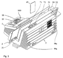
- FIG. 3 is a perspective view of the franking machine from FIG shown at the back.
- the franking machine consists of a meter 1 and a base 2.
- the latter is with a chip card read / write unit 70 equipped, which is arranged behind the guide plate 20 and from the Upper housing edge 22 is accessible.
- a chip card 49 is turned upwards inserted into the slot 72 below.
- the guide plate is in contact with the input data a franking stamp 31 printed.
- the letter feed opening is through a transparent plate 21 and the guide plate 20 laterally limited.
- the Status display of the plugged onto the main board 9 of the meter 1 Security module 100 is visible from the outside through an opening 109.
- FIG. 4 shows a block diagram of the postal security module PSM 100 in a preferred variant.
- the negative pole of the battery 134 is grounded and a pin P23 of the contact group 102.
- the positive pole of the battery 134 is connected via line 193 to one input of voltage changeover switch 180 and line 191 carrying system voltage is connected to the other input of voltage changeover switch 180.
- the SL-389 / P is suitable as a battery 134 for a lifespan of up to 3.5 years or the SL-386 / P for a lifespan of up to 6 years with a maximum power consumption by the PSM 100 commercially available circuit type ADM 8693ARN can be used.
- the output of the voltage changeover switch 180 is connected to the battery monitoring unit 12 and the detection unit 13 via the line 136.
- the battery monitoring unit 12 and the detection unit 13 are in communication with the pins 1, 2, 4 and 5 of the processor 120 via the lines 135, 164 and 137, 139.
- the output of the voltage changeover switch 180 is also present via the line 136 at the supply input of a first memory SRAM, which becomes a non-volatile memory NVRAM of a first technology due to the existing battery 134.
- the security module is connected to the franking machine via the system bus 115, 117, 118.
- Processor 120 can communicate with a remote data center through the system bus and modem 83.
- the billing is performed by the ASIC 150 and checked by the processor 120.
- the postal accounting data are stored in non-volatile memories of different technologies.
- the system voltage is present at the supply input of a second memory NV-RAM 114.
- the latter is a non-volatile memory NVRAM of a second technology, (SHADOW-RAM).
- This second technology preferably comprises a RAM and an EEPROM, the latter automatically taking over the data content in the event of a system power failure.
- the NVRAM 114 of the second technology is connected to the corresponding address and data inputs of the ASIC 150 via an internal address and data bus 112, 113.
- the ASIC 150 contains at least one hardware accounting unit for the Calculation of the postal data to be saved.
- PAL 160 is access logic to the ASIC 150 housed.
- the ASIC 150 is controlled by the PAL 160 logic.
- An address and control bus 117, 115 from the main board 9 is on corresponding pins of the logic PAL 160 and the PAL 160 generates at least one control signal for the ASIC 150 and one Control signal 119 for the program memory FLASH 128.
- the processor 120 executes a program that is stored in the FLASH 128.
- the Processor 120, FLASH 28, ASIC 150 and PAL 160 are one internal system bus interconnected, the lines 110,111,126,119 for data, address and control signals.
- the processor 120 of the security module 100 is via an internal module Data bus 126 with a FLASH 128 and with the ASIC 150 connected.
- the FLASH 128 is supplied with system voltage Us +. He is for example a 128 Kbyte FLASH memory of the type AM29F010-45EC.
- the ASIC 150 of the postal security module 100 delivers an internal address bus 110 addresses 0 to 7 to corresponding address inputs of the FLASH 128.
- the processor 120 of the Security module 100 delivers the via an internal address bus 111 Addresses 8 to 15 to the corresponding address inputs of the FLASH 128.
- the ASIC 150 of the security module 100 is above the Contact group 101 of the interface 8 with the data bus 118, with the Address bus 117 and control bus 115 of the motherboard 9 in Communication link.
- processor 120 has memory 122, 124 on which via line 138 has an operating voltage Ub + of one Voltage monitoring unit 12 is supplied.
- one Real time clock RTC 122 and memory RAM 124 are from one Operating voltage supplied via line 138.
- the voltage monitoring unit (Battery Observer) 12 also provides a status signal 164 and responds to a control signal 135.
- the voltage switch 180 gives as output voltage on line 136 for the Battery Observer 12 and memory 116 that of its input voltages as Supply voltage that is greater than the other.
- the battery 134 of the security module 100 feeds during the idle times the real-time clock in the aforementioned manner outside of normal operation (RTC) 122 with date and / or time registers and / or the static RAM (SRAM) 124, which holds security-relevant data.
- RTC normal operation
- SRAM static RAM
- the tension drops the battery during battery operation below a certain Limit, the voltage monitoring unit 12 becomes the feed point for the RTC and SRAM connected to ground until reset. The voltage on the RTC and SRAM is then 0V.
- Leading the SRAM 124 e.g. important cryptographic keys contains, is deleted very quickly.
- the RESET unit 130 is connected via line 131 to pin 3 of the Processor 120 and connected to a pin of the ASIC's 150.
- the Processor 120 and the ASIC 150 are when the Supply voltage through a reset generation in the RESET unit 130 reset.
- the processor can change the state of the circuit query (status signal) and thus and / or via the evaluation of the Contents of the deleted memory indicate that the Battery voltage has fallen below a certain value in the meantime Has.
- the processor can reset the monitoring circuit, i.e. "make sharp.
- the unplugged detection unit 13 has for measuring the input voltage a line 192 through the connector of the security module and interface 8, preferably via a base on the motherboard 9 the franking machine is connected to ground. This measurement is used for static monitoring of being plugged in and forms the basis for monitoring at a first level. It is envisaged that the Unplugged detection unit 13 circuit means for a resettable Exhibits self-retention, whereby self-retention is triggered, when the voltage level on a measuring voltage line 192 of deviates from a predetermined potential.
- the evaluation logic includes the processor connected to the other functional units 120, which is programmed, the respective state of the security module 100 determine and change. The state of the Latching is via line 139 from processor 120 of the Security module 100 can be queried.
- the measuring voltage potential on the Line 192 corresponds to ground potential when the security module 100 is properly inserted.
- Operating voltage potential is on line 139.
- Ground voltage potential is present on line 139, if the security module 100 is not plugged in.
- the processor 120 points a fifth pin 5, to which line 139 is connected, to query the status of the unplugged detection unit 13 whether it is switched to ground potential with latching. To the state the latching of the unplugged detection unit 13 via the To reset line 137, processor 120 has a fourth pin 4 on.
- a current loop 18 is provided which pins 6 and 7 of the Processor 120 also via the connector of the security module and with each other via the base on the main board 9 of the franking machine connects.
- the lines on pins 6 and 7 of processor 120 are only with a PSM 100 plugged into the main board 9 Current loop 18 closed. This loop forms the basis for dynamic monitoring of the security module being connected on a second level.
- the processor 120 internally has a processing unit CPU 121, one Real time clock RTC 122, a RAM unit 124 and an input / output unit 125 on.
- the processor 120 has at least pins 8, 9 for output a signal for signaling the state of the safety module 100 equipped. I / O ports of the input / output unit are located at pins 8 and 9 125, to which module-internal signaling means are connected, for example colored light emitting diodes LED's 107, 108, which the Signal the status of the safety module 100.
- the security modules can assume various states in their life cycle. So e.g. be detected whether the module is valid cryptographic Contains key. It is also important to differentiate whether that Module works or is defective. The exact type and number of Module states depend on the functions implemented in the module and on the Implementation dependent.
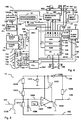
- the circuit diagram of the detection unit 13 is explained. It is provided that the unplugged detection unit 13 has a voltage divider which consists of a series connection of resistors 1310, 1312, 1314 and is connected between a supply voltage potential tapped by a capacitor 1371 and a measuring voltage potential on line 192.
- the circuit is supplied with the system or battery voltage via line 136.
- the respective supply voltage from line 136 reaches the capacitor 1371 of the circuit via a diode 1369.
- a negator 1320, 1398 is located on the output side of the circuit. In the normal state, the transistor 1320 of the negator is blocked and the supply voltage is effective via the resistor 1398 on the line 139, which therefore leads to logic '1', ie H level in the normal state.
- An L level on line 139 is advantageous as a status signal for being unplugged because then no current flows into pin 5 of processor 120, which increases battery life.
- the diode 1369 preferably in conjunction with an electrolytic capacitor 1371, ensures that the circuit upstream of the negator is supplied with a voltage over a relatively long period (> 2 s) at which its function is guaranteed, even though the voltage on line 136 is already was switched off.
- the voltage divider 1310, 1312, 1314 has a tap 1304, to which a capacitor 1306 and the non-inverting input of a comparator 1300 are connected.
- the inverting input of the comparator 1300 is connected to a reference voltage source 1302.
- the output of the comparator 1300 is connected on the one hand via the negator 1324, 1398 to the line 139 and on the other hand to the control input of a switching means 1322 for the self-holding.
- the switching means 1322 is connected in parallel to the resistor 1310 of the voltage divider and the switching means 1316 for resetting the latching is connected between the tap 1304 and ground.
- the tap 1304 of the voltage divider lies at the connection point of the resistors 1312 and 1314.
- the capacitor 1306 connected between the tap 1304 and ground prevents vibrations.
- the voltage at tap 1304 of the voltage divider is compared in comparator 1300 with the reference voltage of source 1302.
- the comparator output remains at L level and transistor 1320 of the negator is blocked.
- line 139 now receives the operating voltage potential and the status signal is logically '1'.
- the voltage divider is dimensioned such that, at ground potential on line 192, tap 1304 carries a voltage which is safely below the switching threshold of comparator 1300. If the connection is interrupted and the line 192 is no longer connected to ground because the security module 100 has been detached from the base on the main board 9 or interface unit 8 of the franking machine, the voltage at the tap 1304 is drawn via the voltage of the reference voltage source 1302 and the Comparator 1300 switches.
- the comparator output is switched to H level and consequently transistor 1320 is switched on.
- line 139 is connected to ground potential and the status signal is logically '0'.
- a transistor 1322 which is connected in parallel with the resistor 1310 of the voltage divider, a self-holding circuit of the unplugged detection unit 13 is realized.
- the control input of transistor 1322 is switched to H level by the comparator output.
- the transistor 1322 turns on and bridges the resistor 1310.
- the voltage divider is only formed by the resistors 1312 and 1314.
- the switchover threshold is increased to such an extent that the comparator also remains in the switched state when the line 192 is again at ground potential because the safety module has been plugged in again.
- the state of the circuit can be queried by the processor 120 via the signal on line 139.
- the unplugged detection unit 13 has a line 137 as a switching means and a switching means 1316 for resetting the latching, the resetting being able to be triggered by the processor 120 via a signal on the line 137.
- the processor 120 can contact a remote data center at any time via a user circuit ASIC 150, a first contact group 101, a system bus of the control device 1 and, for example, the microprocessor 91 via modem 83, which checks the accounting data and, if necessary, further data to the Processor 120 communicates.
- the user circuit ASIC 150 of the security module 100 is connected to the processor 120 via an internal data bus 126.
- the processor 120 can reset the unplugged detection unit if a reinitialization could be successfully completed using the transmitted data.
- the transistor 1316 is switched through via the reset signal on the line 137 and thus the voltage at the tap 1304 is drawn below the reference voltage of the source 1302 and the transistors 1320 and 1322 are blocked. If the transistor 1322 is blocked in the normal state, the resistors 1310 and 1312 form the upper part of the above-mentioned voltage divider in series and the switching threshold is lowered again to the original state.
- FIG. 6 shows the mechanical structure of the security module in side view.
- the security module is designed as a multi-chip module, i.e. several functional units are on a printed circuit board 106 interconnected.
- the security module 100 is with a hard potting compound 105 potted, the battery 134 of the security module 100 outside the sealing compound 105 on a printed circuit board 106 is interchangeably arranged.
- one Potting material 105 potted that signaling means 107, 108 from the Potting material protrude in a first place and that the Printed circuit board 106 with the inserted battery 134 on the side of a second one Spot protrudes.
- Circuit board 106 also has battery contact terminals 103 and 104 for connecting the poles of the battery 134, preferably on the component side above the circuit board 106. It it is provided that for plugging in the postal security module PSM 100 on the main board of meter 1, the contact groups 101 and 102 below the printed circuit board 106 (conductor track side) of the security module 100 are arranged. The ASIC 150 user circuit has stopped via the first contact group 101 - in a manner not shown - with the System bus of a control device 1 in communication connection and the second contact group 102 is used to supply the security module 100 with the system voltage.
- the security module on the Main board plugged in is preferably inside the meter housing arranged in such a way that the signaling means 107, 108 are close an opening 109 or protrudes into this.
- the meter case is thus advantageously constructed so that the user can view the status of the Security module can still see from the outside.
- the two LEDs 107 and 108 of the signaling means are via two output signals of the I / O ports on pins 8, 9 of processor 120 are controlled. Both LEDs are housed in a common component housing (Bicolor LED), which is why the dimensions or diameter the opening can remain relatively small and of the order of magnitude Signal means is. In principle, three different colors can be displayed (red, green, orange), of which only two are used (red and green). To differentiate the status, the LEDs also flash used, so that 5 different status groups can be distinguished can be characterized by the following LED states: LED off, LED flashing red, LED red, LED flashing green, LED green.
- FIG. 7 is a top view of the postal security module shown.
- FIGS. 8a and 8b each show a view of the security module from the right or from the left.
- the postal device in particular a franking machine
- the safety module can also have a different design have, which makes it possible, for example, on the motherboard of a personal computer that can be inserted as a PC franking device controls a commercially available printer.
Abstract
Description
Die Erfindung betrifft ein Verfahren zum Schutz eines Sicherheitsmoduls,
gemäß der im Oberbegriff des Anspruchs 1 angegebenen Art, und eine
Anordnung zur Durchführung des Verfahrens, gemäß der im Oberbegriff
des Anspruchs 3 angegebenen Art. Ein solcher postalischer
Sicherheitsmodul ist insbesondere für den Einsatz in einer
Frankiermaschine bzw. Postbearbeitungsmaschine oder Computer mit
Postbearbeitungsfunktion geeignet.The invention relates to a method for protecting a security module,
according to the type specified in the preamble of
Moderne Frankiermaschinen, wie die aus der US 4.746.234 bekannte Thermotransfer-Frankiermaschine, setzen eine vollelektronische digitale Druckvorrichtung ein. Damit ist es prinzipiell möglich, beliebige Texte und Sonderzeichen im Frankierstempeldruckbereich und ein beliebiges oder ein einer Kostenstelle zugeordnetes Werbeklischee zu drucken. So hat zum Beispiel die Frankiermaschine T1000 der Anmelderin einen Mikroprozessor, welcher von einem gesicherten Gehäuse umgeben ist, das eine Öffnung für die Zuführung eines Briefes aufweist. Bei einer Briefzuführung übermittelt ein mechanischer Briefsensor (Mikroschalter) ein Druckanforderungssignal an den Mikroprozessor. Der Frankierabdruck beinhaltet eine zuvor eingegebene und gespeicherte postalische Information zur Beförderung des Briefes. Die Steuereinheit der Frankiermaschine nimmt eine Abrechnung softwaremäßig vor, übt eine Überwachungsfunktion ggf. bezüglich der Bedingungen für eine Datenaktualisierung aus und steuert das Nachladen eines Portwertguthabens.Modern franking machines, such as that known from US 4,746,234 Thermal transfer franking machine, set a fully electronic digital Printing device. In principle, it is possible to use any text and Special characters in the franking stamp printing area and any or print an advertising slogan assigned to a cost center. So had for example the applicant's franking machine T1000, a microprocessor, which is surrounded by a secured housing that has an opening for feeding a letter. With a letter feed transmits a mechanical letter sensor (microswitch) Pressure request signal to the microprocessor. The franking imprint contains previously entered and stored postal information to carry the letter. The control unit of the franking machine performs software billing, exercises a monitoring function possibly with regard to the conditions for a data update and controls the reloading of a port credit.
Für die oben genannte Thermotransfer-Frankiermaschine wurde bereits in US 5,606,508 (DE 42 13 278 B1) und in US 5,490,077 eine Dateneingabemöglichkeit mittels Chipkarten vorgeschlagen. Eine der Chipkarten lädt neue Daten in die Frankiermaschine und ein Satz an weiteren Chipkarten gestattet durch das Stecken einer Chipkarte eine Einstellung entsprechend eingespeicherter Daten vorzunehmen. Das Datenladen und die Einstellung der Frankiermaschine kann damit bequemer und schneller als per Tastatureingabe erfolgen. Eine Frankiermaschine zum Frankieren von Postgut, ist mit einem Drucker zum Drucken des Postwertstempels auf das Postgut, mit einer Steuerung zum Steuern des Druckens und der peripheren Komponenten der Frankiermaschine, mit einer Abrecheneinheit zum Abrechnen von Postgebühren, mit mindestens einem nichtflüchtigen Speicher zum Speichern von Postgebührendaten, mit mindestens einem nichtflüchtigen Speicher zum Speichern von sicherheitsrelevanten Daten und mit einer Kalender/Uhr ausgestattet. Der nichtflüchtige Speicher der sicherheitsrelevanten Daten und/oder die Kalender/Uhr wird gewöhnlich von einer Batterie gespeist. Bei bekannten Frankiermaschinen werden sicherheitsrelevante Daten (kryptografische Schlüssel u.ä.) in nichtflüchtigen Speichern gesichert. Diese Speicher sind EEPROM, FRAM oder batteriegesicherte SRAM. Bekannte Frankiermaschinen verfügen oft auch über eine interne Echtzeituhr (Real Time Clock) RTC, die von einer Batterie gespeist wird. Bekannt sind z.B. vergossene Module, die integrierte Schaltkreise und eine Lithium-Batterie enthalten. Diese Module müssen nach Ablauf der Lebensdauer der Batterie im Ganzen ausgetauscht und entsorgt werden. Aus wirtschaftlichen und ökologischen Gesichtspunkten ist es günstiger, wenn nur die Batterie ausgetauscht werden muß. Dazu muß jedoch das Sicherheitsgehäuse geöffnet und anschließend wieder verschlossen und gesiegelt werden, denn die Sicherheit gegenüber Betrugsversuchen beruht im Wesentlichen auf dem gesicherten Gehäuse, welches die gesamte Maschine umschließt. Seitens der Anmelderin wurde in EP 660 269 A2 (US 5,671,146) bereits ein geeignetes Verfahren zur Verbesserung der Sicherheit von Frankiermaschinen vorgeschlagen, in welchem zwischen einem authorisierten und unauthorisierten Öffnen des Sicherheitsgehäuses unterschieden wird.For the thermal transfer franking machine mentioned above, was already in US 5,606,508 (DE 42 13 278 B1) and in US 5,490,077 a data input option proposed by means of chip cards. One of the Chip cards load new data into the franking machine and a set additional chip cards are permitted by inserting a chip card Make settings according to stored data. The Data loading and the setting of the franking machine can be done with it more convenient and faster than using the keyboard. A Franking machine for franking mail, is with a printer for Printing the postage stamp on the mail, with a control for Control the printing and peripheral components of the Franking machine, with a billing unit for billing Postage, with at least one non-volatile memory for Storage of postage data, with at least one non-volatile Memory for storing safety-relevant data and with one Calendar / clock equipped. The non-volatile memory of the safety-relevant Dates and / or the calendar / clock is usually from one Battery powered. Known franking machines are security-relevant Data (cryptographic keys, etc.) in non-volatile Save saved. These memories are EEPROM, or FRAM battery-backed SRAM. Known franking machines often also have via an internal real time clock (RTC), which is controlled by a Battery is powered. For example, potted modules that Integrated circuits and a lithium battery included. These modules after the end of the battery life as a whole exchanged and disposed of. From economic and ecological From a point of view, it is cheaper if only the battery is replaced must become. To do this, however, the safety housing must be opened and then be closed and sealed again because the Security against attempted fraud is essentially based on the secured housing that encloses the entire machine. On the part of the applicant has already been described in EP 660 269 A2 (US 5,671,146) appropriate method to improve the security of Franking machines proposed, in which between one authorized and unauthorized opening of the security housing is distinguished.
Eine eventuell erforderliche Reparatur einer Frankiermaschine ist dann vor Ort nur schwer möglich, wenn der Zugang zu den Bauteilen erschwert oder eingeschränkt ist. Bei größeren Postverarbeitungsmaschinen oder sogenannten PC-Frankierern wird zukünftig das gesicherte Gehäuse auf das sogenannte postalische Sicherheitsmodul reduziert werden, was die Zugänglichkeit zu den übrigen Bauteilen verbessern kann.Zum wirtschaftlichen Austauschen der Batterie des Sicherheitsmoduls wäre es außerdem wünschenswert, daß sich diese auf relativ einfachem Wege auswechseln läßt. Dazu muß sich die Batterie außerhalb des Sicherheitsbereichs der Frankiermaschine befinden. Wenn die Batterieklemmen aber von außen zugänglich gemacht werden, ist ein möglicher Angreifer in der Lage, die Batteriespannung zu manipulieren. Bekannte batteriegespeiste SRAM und RTC haben bzgl. ihrer geforderten Betriebsspannung unterschiedliche Anforderungen. Die notwendige Spannung zum Halten von Daten von SRAM liegt unterhalb der geforderten Spannung zum Betrieb von RTC. Daß bedeutet, daß ein Verringern der Spannung unter einen bestimmten Grenzwert zu einem unerwünschten Verhalten der Komponenten führt: Die RTC bleibt stehen, die Uhrzeit - gespeichert in SRAM-Zellen - und die Speicherinhalte des SRAM bleiben erhalten. Wenigstens eine der Sicherheitsmaßnahmen, beispielsweise Long Time Watchdogs, wären dann auf der Frankiermaschinenseite unwirksam. Unter Long Time Watchdogs wird folgendes verstanden: Die entfernte Datenzentrale gibt einen Zeitkredit bzw. eine Zeitdauer, insbesondere eine Anzahl von Tagen, oder einen bestimmten Tag vor, bis zu welchem sich die Frankiereinrichtung per Kommunikationsverbindung melden kann. Nach erfolglosen Ablauf des Zeitkredits oder der Frist wird das Frankieren verhindert. Unter dem Titel: Verfahren und Anordnung zur Erzeugung und Überprüfung eines Sicherheitsabdruckes wurde bereits in der EP 660 270 A2 (US 5,680,463) ein Verfahren vorgeschlagen, die voraussichtliche Zeitdauer bis zur nächsten Guthabennachladung zu ermitteln, wobei seitens einer Datenzentrale diejenige Frankiermaschine als suspekt gilt, welche sich nicht fristgemäß meldet. Suspekte Frankiermaschinen werden der Postbehörde mitgeteilt, welche den Poststrom nach von suspekten Frankiermaschinen frankierten Briefen überwacht. Ein Ablauf des Zeitkredits oder der Frist wird bereits auch von der Frankiereinrichtung ermittelt und der Benutzer wird aufgefordert die überfällige Kommunikation durchzuführen.A postage meter repair that may be necessary is then difficult on site if access to the components is difficult or is restricted. For larger mail processing machines or So-called PC frankers, the secured housing will be opened in the future the so-called postal security module can be reduced, which the Accessibility to the other components can improve economic It would also be replacing the battery of the security module desirable that they exchange in a relatively simple way leaves. To do this, the battery must be outside the safety zone the franking machine. If the battery terminals though being made accessible from the outside is a possible attacker in the Able to manipulate the battery voltage. Known battery powered SRAM and RTC have different operating voltage requirements Conditions. The necessary tension to hold SRAM data is below the required voltage to operate from RTC. That means reducing the tension under one certain limit value for undesired behavior of the components leads: The RTC stops, the time - stored in SRAM cells - And the memory contents of the SRAM are retained. At least one of the security measures, such as long time watchdogs, would then be ineffective on the franking machine side. Under long time Watchdogs understood the following: The remote data center gives a time credit or a period, in particular a number of Days, or a certain day before, by which the franking device can report via communication link. After unsuccessful Franking is prevented from expiry of the time credit or the deadline. Under the title: Process and arrangement for generation and verification A security imprint was already in EP 660 270 A2 (US 5,680,463) proposed a method, the expected time until the next credit reload, on the part of In a data center, the postage meter machine that is suspect is suspect does not report on time. Suspect franking machines become the Postal authority notified the post stream of suspicious franking machines franked letters monitored. An expiration of the time credit or the deadline is already determined by the franking device and the user is prompted for overdue communication perform.
Sicherheitsmodule sind von elektronischen Datenverarbeitungsanlagen her bereits bekannt. Zum Schutz vor Einbruch in eine elektronische Anlage wird in EP 417 447 B1 bereits eine Sperre vorgeschlagen, welche Stromversorgungsmittel- und Signalerfassungsmittel sowie Abschirmmittel im Gehäuse umfaßt. Das Abschirmmittel besteht aus Einkapselungsmaterial und Leitungsmitteln, an welchen die Stromversorgungs- und Signalerfassungsmittel angeschlossen sind. Letzteres reagiert auf eine Veränderung des Leitungswiderstandes des Leitungsmittels. Außerdem enthält das Sicherheitsmodul eine interne Batterie, einen Spannungsumschalter von Systemspannung auf Batteriespannung, ein Power Gate und einen Kurzschlußtransistor sowie weitere Sensoren. Wenn die Spannung eine bestimmte Grenze unterschreitet, reagiert das Power Gate. Wenn der Leitungswiderstand, die Temperatur oder die Strahlung verändert ist, reagiert die Logik. Mittels des Power Gate oder mittels der Logik wird der Ausgang des Kurzschlußtransistor auf L-Pegel umgeschaltet, wodurch ein im Speicher gespeicherter kryptographischer Schlüssel gelöscht wird. Jedoch ist die Lebensdauer der nicht auswechselbaren Batterie und damit des Sicherheitsmoduls für den Einsatz in Frankiereinrichtungen bzw. Postverarbeitungsmaschinen zu klein.Security modules are from electronic data processing systems already known here. To protect against intrusion into an electronic In EP 417 447 B1, a lock is already proposed, which Power supply and signal detection means and shielding means includes in the housing. The shielding agent consists of encapsulation material and line means to which the power supply and Signal acquisition means are connected. The latter responds to one Change in the line resistance of the line means. Moreover the safety module contains an internal battery, a voltage switch from system voltage to battery voltage, a power gate and a short-circuit transistor and other sensors. If the If the voltage drops below a certain limit, the power reacts Gate. If the line resistance, the temperature or the radiation the logic reacts. Using the Power Gate or the Logic, the output of the short-circuit transistor is switched to L level, whereby a cryptographic stored in memory Key is deleted. However, the lifespan is non-interchangeable Battery and thus the safety module for use in Franking equipment or mail processing machines too small.
Eine größere Postverarbeitungsmaschine ist beispielsweise die JetMail®. Ein Frankierdruck wird hier mittels einem stationär angeordneten Tintenstrahldruckkopf bei einem nichtwaagerechten annähernd vertikalen Brieftransport erzeugt. Eine geeignete Ausführung für eine Druckvorrichtung wurde bereits in der DE 196 05 015 C1 vorgeschlagen. Die Postverarbeitungsmaschine hat ein Meter und eine Base. Soll das Meter mit einem Gehäuse ausgestattet werden, so daß Bauteile leichter zugänglich sind, dann muß es durch ein postalisches Sicherheitsmodul vor Betrugsversuchen geschützt werden, welches mindestens das Abrechnen der Postgebühren durchführt. Um Einflüsse auf den Programmverlauf auszuschließen, wurde bereits in der EP 789 333 A2 unter dem Titel: Frankiermaschine vorgeschlagen, ein Sicherheitsmodul mit einer Anwenderschaltung (Application Specific Integrated Circuit) ASIC auszustatten, die eine Hardware-Abrecheneinheit aufweist. Die Anwenderschaltung steuert außerdem die Druckdatenübertragung zum Druckkopf. A larger mail processing machine is, for example, the JetMail®. A franking imprint is arranged here by means of a stationary one Inkjet printhead with a non-horizontal approximately vertical Letter transport generated. A suitable version for one Printing device has already been proposed in DE 196 05 015 C1. The mail processing machine has a meter and a base. Should that Meters can be equipped with a housing, making components lighter accessible, then it must be through a postal security module be protected from attempted fraud, which includes at least billing who carries out postage. To influence the course of the program exclude was already in EP 789 333 A2 under the Title: Postage meter proposed a security module with a Equip user circuit (Application Specific Integrated Circuit) ASIC, which has a hardware accounting unit. The user circuit also controls the print data transfer to the print head.
Letzteres wäre nur dann nicht erforderlich, wenn für jedes Poststück einzigartige Abdrucke erzeugt werden. Ein geeignetes Verfahren und Anordnung zur Erzeugung und Überprüfung eines Sicherheitsabdruckes ist beispielsweise in den US 5,680,463, US 5,71 2,916 und US 5,734,723 vorgeschlagen worden. Dabei wird eine spezielle Sicherheitsmarkierung elektronisch generiert und in das Druckbild eingebettet.The latter would not be necessary only if for each item of mail unique prints are created. A suitable procedure and Arrangement for generating and checking a security imprint is for example in US 5,680,463, US 5,71 2,916 and US 5,734,723 been proposed. A special security marking is used generated electronically and embedded in the printed image.
Weitere Maßnahmen zum Schutz eines Sicherheitsmodul vor einem Angriff auf die in ihm gespeicherten Daten wurden auch in den nicht vorveröffentlichten deutschen Anmeldungen 198 16 572.2 und 198 16 571.4 vorgeschlagen. Bei einer Vielzahl von Sensoren steigt der Stromverbrauch und ein nicht ständig von einer Systemspannung versorgter Sicherheitsmodul zieht dann den für die Sensoren benötigten Strom aus seiner internen Batterie, was letztere ebenfalls frühzeitig erschöpft. Die Kapazität der Batterie und der Stromverbrauch beschränken somit die Lebensdauer eines Sicherheitsmoduls.Further measures to protect a security module from Attack on the data stored in it were also not in the Pre-published German applications 198 16 572.2 and 198 16 571.4 proposed. With a large number of sensors, the Power consumption and one not constantly from a system voltage The supplied security module then pulls the one required for the sensors Power from its internal battery, which also depletes the latter at an early stage. Limit battery capacity and power consumption thus the lifespan of a security module.
Frankiermaschinen sind wie viele andere Produkte ebenfalls modular aufgebaut. Diese Modularität ermöglicht den Austausch von Modulen und Komponenten aus verschiedenen Gründen. So können z.B. defekte Module ausgetauscht und durch überprüfte, reparierte oder neue Module ersetzt werden. Da eine höchste Sorgsamkeit beim Austausch von Baugruppen erforderlich ist, die sicherheitsrelevante Daten enthalten, erfordert der Austausch in der Regel den Einsatz eines Service Technikers und Maßnahmen, die bei unsachgemäßem Gebrauch bzw. unauthorisierten Austausch eines Sicherheitsmoduls dessen Funktionsweise unterbinden. Letzteres ist aber sehr aufwendig.Like many other products, franking machines are also modular built up. This modularity enables the exchange of modules and Components for various reasons. For example, defective Modules exchanged and checked, repaired or new modules be replaced. Because the greatest care when exchanging Assemblies that contain safety-relevant data are required, The exchange usually requires the use of a service Technician and measures taken in the event of improper use or unauthorized replacement of a security module and its functionality prevent. The latter is very complex.
Der Erfindung liegt die Aufgabe zugrunde, mit geringem Aufwand den Schutz vor einem unbefugt manipulierten Sicherheitsmodul zu gewährleisten, wenn das Sicherheitsmodul austauschbar angeordnet ist. Der Austausch soll von jederman auf möglichst einfache Weise möglich sein.The invention is based, with little effort the task To ensure protection against an unauthorized manipulated security module, if the security module is arranged interchangeably. The Exchange should be possible in the simplest possible way.
Die Aufgabe wird mit den Merkmalen des Verfahrens nach Anspruch 1
und mit den Merkmalen der Anordnung nach Anspruch 3 gelöst.The object is achieved with the features of the method according to
Die Erfindung geht davon aus, mittels Funktionseinheiten den Austausch und Gebrauch eines Sicherheitsmoduls einer Frankiermaschine, Postverarbeitungseinrichtung oder ähnlichen Gerätes festzustellen, um den Benutzern der verschiedenen Geräte eine Gewährleistung über die korrekte Funktionsweise des Sicherheitsmoduls und damit des gesamten Gerätes bieten zu können. Ein Austausch eines Sicherheitsmoduls wird mindestens detektiert und ggf. nachträglich als Zustand signalisiert, wenn der Sicherheitsmodul wieder gesteckt ist und mit einer Systemspannung versorgt wird. Die Veränderungen des Zustandes des Sicherheitsmoduls werden mittels einer ersten Funktionseinheit und mittels einer von einer Batterie versorgten Detektionseinheit erfaßt, welche eine rücksetzbare Selbsthaltung aufweist. Die erste Funktionseinheit kann den jeweiligen Zustand auswerten, wenn sie wieder mit Systemspannung versorgt wird. Die Vorteile liegen in einer schnellen Reaktion auf Veränderungen des Zustandes des Sicherheitsmoduls und in einem geringem Batteriestromverbrauch der Schaltung der Detektionseinheit während der Nichtversorgung des Sicherheitsmoduls mit der Systemspannung.The invention is based on the exchange by means of functional units and use of a security module of a franking machine, Postprocessing device or similar device to determine guarantee the users of the various devices about the correct functioning of the security module and thus of the whole Device. An exchange of a security module will at least detected and, if necessary, subsequently signaled as a condition if the safety module is plugged in again and with a system voltage is supplied. Changes in the state of the security module are by means of a first functional unit and by means of one Battery powered detection unit detects a resettable Exhibits self-retention. The first functional unit can each Evaluate the condition when it is supplied with system voltage again. The advantages are a quick reaction to changes in the State of the safety module and low battery power consumption the circuit of the detection unit during the Failure to supply the safety module with the system voltage.
Es ist mindestens vom unsachgemäßem Gebrauch eines Sicherheitsmoduls bei jedem Austausch auszugehen, bei welchen nicht nur die Systemspannung fehlt, sondern auch die austauschbar angeordnete Batterie entfernt wird. Damit der Austausch von möglichst gering qualifiziertem Personal und in Zukunft gar durch den Benutzer ausgeführt werden kann, übernimmt eine weitere Funktionseinheit die Überwachung auf Spannungsausfall beim Austausch der Batterie, wobei die erste Funktionseinheit zunächst sensitive Daten löscht und damit den weiteren Gebrauch des Sicherheitsmoduls einschränkt oder gar unterbindet. Die erste Funktionseinheit erzwingt bei einer späteren Wiederinbetriebnahme eine Kontaktaufnahme des Sicherheitsmoduls mit einer entfernten Datenzentrale zum Freischalten mindestens einer Funktionseinheit. Falls der Sicherheitsmodul sachgemäß ausgetauscht wurde, werden bei der Wiederinbetriebnahme die sensitiven Daten reinitialisiert. Zur Kontaktaufnahme sind Verfahren mit einer digitalen oder analogen Übertragungsstrecke einsetzbar. Das Verfahren zum Schutz eines Sicherheitsmoduls beinhaltet die folgenden Schritte:
- Überwachung des sachgemäßen Gebrauchs oder Austausches des Sicherheitsmoduls mittels einer ersten, zweiten und dritten Funktionseinheit,
- Löschen von sensitiven Daten aufgrund eines unsachgemäßen Gebrauchs oder Austausches mindestens mittels der zweiten Funktionseinheit,
- Sperren der Funktionalität mittels der dritten Funktionseinheit während eines Austausches des Sicherheitsmoduls,
- Reinitialisieren mittels der ersten Funktionseinheit von zuvor gelöschten sensitiven Daten nach sachgemäßem Gebrauch oder Austausch des Sicherheitsmoduls,
- Wiederinbetriebnahme durch Freischalten der Funktionseinheiten des Sicherheitsmodules.
- Monitoring the proper use or replacement of the security module using a first, second and third functional unit,
- Deletion of sensitive data due to improper use or exchange at least by means of the second functional unit,
- Blocking of the functionality by means of the third functional unit during an exchange of the security module,
- Reinitialization by means of the first functional unit of previously deleted sensitive data after proper use or replacement of the security module,
- Recommissioning by activating the functional units of the safety module.
Es ist vorgesehen, daß das Reinitialisieren in Verbindung mit einer Kommunikation mittels einer entfernten Datenzentrale von der ersten Funktionseinheit vorgenommen wird, nachdem eine dynamische GestecktseinDetektion erfolgreich durchgeführt wurde, wobei während der Detektion von der ersten Funktionseinheit über eine Stromschleife der Interfaceeinheit Informationen ausgetauscht werden, deren fehlerfreie Übermittlung den Beweis für den sachgemäßen Einbau des Sicherheitsmodules erbringt. Das Freischalten von Funktionseinheiten des Sicherheitsmodules erfolgt durch deren Rücksetzen. Die erste Funktionseinheit ist ein mit den anderen Funktionseinheiten verbundener Prozessor, welcher programmiert ist, den jeweiligen Zustand festzustellen. Die zweite Funktionseinheit ist eine Spannungsüberwachungseinheit mit rücksetzbarer Selbsthaltung und die dritte Funktionseinheit ist eine Ungestecktsein-Detektionsschaltung mit rücksetzbarer Selbsthaltung.Reinitialization is intended to be associated with communication by means of a remote data center from the first functional unit is carried out after a dynamic plugged-in detection was successfully carried out during the detection from the first functional unit via a current loop of the interface unit Information is exchanged, its error-free transmission proof of the correct installation of the safety module he brings. The activation of functional units of the safety module is done by resetting them. The first functional unit is a with processor connected to the other functional units, which programs is to determine the respective state. The second functional unit is a voltage monitoring unit with resettable Self-holding and the third functional unit is an unplugged detection circuit with resettable self-holding.
Vorteilhafte Weiterbildungen der Erfindung sind in den Unteransprüchen gekennzeichnet bzw. werden nachstehend zusammen mit der Beschreibung der bevorzugten Ausführung der Erfindung anhand der Figuren näher dargestellt. Es zeigen:
Figur 1,- Blockbild und Interface des Sicherheitsmoduls,
Figur 2,- Blockschaltbild der Frankiermaschine,
Figur 3,- Perspektivische Ansicht der Frankiermaschine von hinten,
Figur 4,- Blockschaltbild des Sicherheitsmoduls (zweite Variante),
Figur 5,- Schaltbild der Detektionseinheit,
Figur 6,- Seitenansicht des Sicherheitsmoduls,
Figur 7,- Draufsicht auf das Sicherheitsmodul,
- Figur 8a,
- Ansicht des Sicherheitsmoduls von rechts,
- Figur 8b,
- Ansicht des Sicherheitsmoduls von links.
- Figure 1,
- Block diagram and interface of the security module,
- Figure 2,
- Block diagram of the franking machine,
- Figure 3,
- Perspective view of the franking machine from behind,
- Figure 4,
- Block diagram of the security module (second variant),
- Figure 5,
- Circuit diagram of the detection unit,
- Figure 6,
- Side view of the security module,
- Figure 7,
- Top view of the security module,
- Figure 8a,
- View of the security module from the right,
- Figure 8b,
- View of the security module from the left.
In der Figur 1 ist ein Blockbild des Sicherheitsmoduls 100 mit den
Kontaktgruppen 101, 102 zum Anschluß an ein Interface 8 sowie mit den
Batteriekontaktklemmen 103 und 104 eines Batterieinterfaces für eine
Batterie 134 dargestellt. Obwohl das Sicherheitsmodul 100 mit einer
harten Vergußmasse vergossen ist, ist die Batterie 134 des
Sicherheitsmoduls 100 außerhalb der Vergußmasse auf einer Leiterplatte
auswechselbar angeordnet. Die Leiterplatte trägt die Batteriekontaktklemmen
103 und 104 für den Anschluß der Pole der Batterie 134. Mittels
der Kontaktgruppen 101, 102 wird das Sicherheitsmodul 100 an ein
entsprechendes Interface 8 der Hauptplatine (Motherboard) 9 gesteckt.
Die erste Kontaktgruppe 101 steht mit dem Systembus einer Steuereinrichtung
in Kommunikationsverbindung und die zweite Kontaktgruppe
102 dient der Versorgung des Sicherheitsmoduls 100 mit der Systemspannung.
Über die Pins P3,P5-P19 der Kontaktgruppe 101 laufen Adreß- und
Datenleitungen 117, 118 sowie Steuerleitungen 115. Die erste
und/oder zweite Kontaktgruppe 101 und/oder 102 sind/ist zur statischen
und dynamischen Überwachung des Angestecktseins des Sicherheitsmoduls
100 ausgebildet. Über die Pins P23 und P25 der Kontaktgruppe
102 wird die Versorgung des Sicherheitsmodul 100 mit der Systemspannung
der Hauptplatine 9 realisiert und über die Pins P1, P2 bzw. P4
wird eine dynamische und statische Ungestecktsein-Detektion durch das
Sicherheitsmodul 100 realisiert.1 shows a block diagram of the
Das Sicherheitsmodul 100 weist in an sich bekannter Weise einen
Mikroprozessor 120 auf, der einen - nicht gezeigten - integrierten
Festwertspeicher (internal ROM) mit dem speziellen Anwendungsprogramm
enthält, was für die Frankiermaschine von der Postbehörde
bzw. vom jeweiligen Postbeförderer zugelassen ist. Alternativ kann an den
internen Datenbus 126 ein üblicher Festwertspeicher ROM oder FLASH-Speicher
angeschlossen werden. The
Das Sicherheitsmodul 100 weist in an sich bekannter Weise eine ResetSchaltungseinheit
130, einen Anwenderschaltkreis ASIC 150 und eine
Logik PAL 160 auf, die für den ASIC als Steuersignalgenerator dient. Die
Reset-Schaltungseinheit 130 bzw. der Anwenderschaltkreis ASIC 150 und
die Logik PAL 160 sowie eventuell weitere - nicht gezeigte - Speicher
werden über die Leitungen 191 bzw. 129 mit Systemspannung Us+
versorgt, welche bei eingeschalteter Frankiereinrichtung von der Hauptplatine
9 geliefert wird. In der EP 789 333 A2 wurden bereits die wesentlichen
Teile eines postalischen Sicherheitsmoduls PSM erläutert, die die
Funktionen Abrechnen und Absichern der Postgebührendaten realisieren.The
Die Systemspannung Us+ liegt außerdem über eine Diode 181 und die
Leitung 136 am Eingang der Spannungsüberwachungseinheit 12 an. Am
Ausgang der Spannungsüberwachungseinheit 12 wird eine zweite Betriebsspannung
Ub+ geliefert, welche über die Leitung 138 zur Verfügung
steht. Bei ausgeschalteter Frankiereinrichtung steht nicht die Systemspannung
Us+, sondern nur die Batteriespannung Ub+ zur Verfügung. Die
am negativen Pol liegende Batteriekontaktklemme 104 ist mit Masse verbunden.
Von der am positiven Pol liegenden Batteriekontaktklemme 103
wird Batteriespannung über eine Leitung 193, über eine zweite Diode 182
und die Leitung 136 an den Eingang der Spannungsüberwachungseinheit
geliefert. Alternativ zu den beiden Dioden 181, 182 kann ein handelsüblicher
Schaltkreis als Spannungsumsohalter 180 eingesetzt werden.The system voltage Us + is also present via a
Der Ausgang der Spannungsüberwachungseinheit 12 ist über eine
Leitung 138 mit einem Eingang für diese zweite Betriebsspannung Ub+
des Prozessors 120 verbunden, welcher mindestens auf einen RAM-Speicherbereich
122, 124 führt und dort eine nichtflüchtige Speicherung
solange garantiert, wie die zweite Betriebsspannung Ub+ in der
erforderlichen Höhe anliegt. Der Prozessor 120 enthält vorzugsweise
einen internen RAM 124 und eine Echtzeituhr (RTC) 122.The output of the
Die Spannungsüberwachungseinheit 12 im Sicherheitsmodul weist eine
rücksetzbare Selbsthaltung auf, die vom Prozessor 120 über eine Leitung
164 abgefragt und über eine Leitung 135 zurückgesetzt werden kann. Für
eine Rücksetzung der Selbsthaltung weist die Spannungsüberwachungseinheit
12 Schaltungsmittel auf Die Rücksetzung ist erst auslösbar, wenn
die Batteriespannung über die vorbestimmte Schwelle angestiegen ist. The
Die Leitungen 135 and 164 sind je mit einem Pin (Pin1 und 2) des
Prozessors 120 verbunden. Die Leitung 164 liefert ein Statussignal an den
Prozessor 120 und die Leitung 135 liefert ein Steuersignal an die
Spannungsüberwachungseinheit 12.The
Die Leitung 136 am Eingang der Spannungsüberwachungseinheit 12
versorgt zugleich eine Ungestecktsein-Detektionseinheit 13 mit Betriebs- oder
Batteriespannung. Die Ungestecktsein-Detektionseinheit 13 gibt auf
der Leitung 139 ein Statussignal an einen Pin 5 des Prozessors 120 ab,
das eine Aussage über den Zustand der Schaltung gibt. Vom Prozessor
120 wird der Zustand der Ungestecktsein-Detektionseinheit 13 über die
Leitung 139 abgefragt. Der Prozessor kann mit einem vom Pin 4 des
Prozessors 120 über die Leitung 137 abgegebenen Signal die Ungestecktsein-Detektionseinheit
13 zurücksetzen. Nach dem Setzen wird eine
statische Prüfung auf Anschluß durchgeführt. Dazu wird über eine Leitung
192 Massepotential abgefragt, welches am Anschluß P4 des Interfaces 8
des postalischen Sicherheitsmoduls PSM 100 anliegt und nur abfragbar
ist, wenn der Sicherheitsmodul 100 ordnungsgemäß gesteckt ist. Bei
gesteckten Sicherheitsmodul 100 wird Massepotential des negativen Pols
104 der Batterie 134 des postalischen Sicherheitsmoduls PSM 100 auf
den Anschluß P23 des Interfaces 8 gelegt und ist somit am Anschluß P4
des Interfaces 8 über die Leitung 192 von der Ungestecktsein-Detektionseinheit
13 abfragbar.The
An den Pins 6 und 7 des Prozessors 120 liegt eine Leitungsschleife,
welche über die Pins P1 und P2 der Kontaktgruppe 102 des Interfaces 8
zum Prozessor 120 zurückgeschleift wird. Zur dynamischen Prüfung des
Angeschlossenseins des postalischen Sicherheitsmoduls PSM 100 an der
Hauptplatine 9 werden vom Prozessor 120 wechselnde Signalpegel in
ganz unregelmäßigen Zeitabständen an die Pin's 6, 7 angelegt und über
die Schleife zurückgeschleift.There is a line loop on
Das postalische Sicherheitsmodul PSM 100 ist mit einer Long-Live-Batterie
bestückt, welches auch eine Überwachung des Gebrauchs
ermöglicht, ohne das das Sicherheitsmodul an einer Systemspannung
eines Postverabeitungseinrichtung liegt. Der sachgemäße Gebrauch,
Betrieb, Installation oder Einbau in der geeigneten Umgebung sind solche
von den Funktionseinheiten des Sicherheitsmoduls zu prüfende
Eigenschaften. Eine Erstinstallation wird vom Hersteller des postalischen
Sicherheitsmoduls vorgenommen. Es ist also nach dieser Erstinstallation
zunächst lediglich zu prüfen, ob das postalische Sicherheitsmodul von
ihrem Einsatzfeld (Postverabeitungseinrichtung) getrennt wird, wobei dies
in der Regel bei einem Austausch erfolgt.
Die Überwachung dieses Zustandes wird von der Ungestecktsein-Detektionseinheit
13 vorgenommen. Hierbei wird über die Masseverbindung
am Pin 4 der Interfaceeinheit 8 ein Spannungspegel überwacht.
Beim Austausch der Funktionseinheit wird diese Masseverbindung unterbrochen
und die Ungestecktsein-Detektionseinheit 13 registriert diesen
Vorgang als Information. Da für jede Trennung des Sicherheitsmoduls 100
von der Interfaceeinheit 8, die Speicherung dieser Information durch den
speziellen batteriegetriebenen Schaltungsaufbau gewährleistet ist, kann
eine Auswertung dieser Information zu jeder Zeit erfolgen, falls eine
Wiederinbetriebnahme gewünscht ist. Die regelmäßige Auswertung
dieses Ungestecktsein-Signals auf der Leitung 139 der Ungestecktsein-Detektionseinheit
13 ermöglicht es dem Prozessor 120 sensitive Daten zu
löschen, ohne jedoch damit die Abrechnungs- und Kundendaten in den
NVRAM-Speichern zu verändern. Der momentane Zustand des postalischen
Sicherheitsmoduls mit den gelöschten sensitiven Daten kann als
Wartungszustand aufgefaßt werden, in welchem in der Regel der Austausch,
eine Reparatur oder sonstiges vorgenommen wird. Da die sensitiven
Daten der Funktionseinheit gelöscht sind, ist ein Fehler aufgrund
einer unsachgemäßen Handhabung des postalischen Sicherheitsmoduls
ausgeschlossen. Die sensitiven Daten sind beispielsweise kryptographische
Schlüssel. Der Prozessor 120 verhindert im Wartungszustand eine
Kernfunktionalität des postalischen Sicherheitsmoduls, welche beispielweise
in der Abrechnung und/oder Berechnung eines Sicherheitscodes für
die Sicherheitsmarkierung in einem Sicherheitsabdruck besteht.
Zur Wiederinbetriebnahme wird das postalische Sicherheitsmodul PSM
zunächst gesteckt und elektrisch mit der entsprechenden Interfaceeinheit
8 eines Postbearbeitungsgerätes verbunden. Anschließend wird das
Gerät eingeschaltet und somit das postalische Sicherheitsmodul wieder
mit Systemspannung Us+ versorgt. Aufgrund des speziellen Zustandes
muß nun der sachgemäße Einbau des postalischen Sicherheitsmoduls
durch ihre Funktionseinheit erneut geprüft werden. Hierfür wird eine
zweite Stufe einer Prüfung (dynamische Gestecktsein-Detektion) vorgesehen.
Über eine zwischen der ersten Funktionseinheit (Prozessor 120)
und der Stromschleife 18 der Interfaceeinheit 8 hergestellten operative
Verbindung werden Informationen ausgetauscht, deren fehlerfreie
Übermittlung den Beweis für den sachgemäßen Einbau erbringt. Dies ist
Voraussetzung für eine erfolgreiche Wiederinbetriebnahme.The postal
This state is monitored by the
To restart, the postal security module PSM is first plugged in and electrically connected to the corresponding
Für den Zustandswechsel in den normalen Betriebszustand ist nun noch
eine Reinitialisierung der sensitiven Daten erforderlich. Zwischen dem
postalischen Sicherheitsmodul und einer dritten Instanz wird eine
Kommunikation vorgenommen, wobei letztere diese sensitiven Daten
übermittelt. Nach erfolgreicher Übermittlung wird die UngestecktseinDetektionseinheit
13 zurückgesetzt und das postalische Sicherheitsmodul
nimmt wieder seinen normalen Betriebszustand ein. Die Wiederinbetriebnahme
ist abgeschlossen.For the change of state in the normal operating state is now still
Reinitialization of sensitive data is required. Between the
postal security module and a third party becomes a
Communication made, the latter this sensitive data
transmitted. After successful transmission, the
Die Figur 2 zeigt ein Blockschaltbild einer Frankiermaschine, die mit
einer Chipkarten-Schreib/Leseeinheit 70 zum Nachladen von Änderungsdaten
per Chipkarte und mit einer Druckeinrichtung 2, welche von einer
Steuereinrichtung 1 gesteuert wird, ausgestattet ist. Die Steuereinrichtung
1 weist eine mit einem Mikroprozessor 91 mit zugehörigen Speichern 92,
93, 94, 95 ausgestattete Hauptplatine 9 auf.FIG. 2 shows a block diagram of a postage meter machine that uses
a chip card read /
Der Programmspeicher 92 enthält ein Betriebsprogramm mindestens zum
Drucken und wenigstens sicherheitsrelevante Bestandteile des Programms
für eine vorbestimmte Format-Änderung eines Teils der
Nutzdaten.
Der Arbeitsspeicher RAM 93 dient zur flüchtigen Zwischenspeicherung
von Zwischenergebnissen. Der nichtflüchtige Speicher NVM 94 dient zur
nichtflüchtigen Zwischenspeicherung von Daten, beispielsweise von
statistischen Daten, die nach Kostenstellen geordnet sind. Der
Kalender/Uhrenbaustein 95 enthält ebenfalls adressierbare aber nichtflüchtige
Speicherbereiche zur nichtflüchtigen Zwischenspeicherung von
Zwischenergebnissen oder auch bekannten Programmteilen (beispielsweise
für den DES-Algorithmus). Es ist vorgesehen, daß die Steuereinrichtung
1 mit der Chipkarten-Schreib/Leseeinheit 70 verbunden ist,
wobei der Mikroprozessor 91 der Steuereinrichtung 1 beispielsweise dazu
programmiert ist, die Nutzdaten N aus dem Speicherbereich einer
Chipkarte 49 zu deren Anwendung in entsprechende Speicherbereiche
der Frankiermaschine zu laden. Eine in einen Einsteckschlitz 72 der
Chipkarten-Schreib/Leseeinheit 70 eingesteckte erste Chipkarte 49
gestattet ein Nachladen eines Datensatzes in die Frankiermaschine für
mindestens eine Anwendung. Die Chipkarte 49 enthält beispielsweise die
Portogebühren für alle üblichen Postbefördererleistungen entsprechend
des Tarifs der Postbehörde und ein Postbefördererkennzeichen, um mit
der Frankiermaschine ein Stempelbild zugenerieren und entsprechend
des Tarifs der Postbehörde die Poststücke freizustempeln.The
The
Die Steuereinrichtung 1 bildet das eigentliche Meter mit den Mitteln 91 bis
95 der vorgenannten Hauptplatine 9 und umfaßt auch eine Tastatur 88,
eine Anzeigeeinheit 89 sowie einen anwendungsspezitischen Schaltkreis
ASIC 90 und das Interface 8 für das postalische Sicherheitsmodul PSM
100. Das Sicherheitsmodul PSM 100 ist über einen Steuerbus mit dem
vorgenannten ASIC 90 und dem Mikroprozessor 91 sowie über den
parallelen µC-Bus mindestens mit den Mitteln 91 bis 95 der Hauptplatine 9
und der mit Anzeigeeinheit 89 verbunden. Der Steuerbus führt Leitungen
für die Signale CE, RD und WR zwischen dem Sicherheits-modul PSM
100 und dem vorgenannten ASIC 90. Der Mikroprozessor 91 weist
vorzugsweise einen Pin für ein vom Sicherheitsmodul PSM 100
abgegebenes Interruptsignal i, weitere Anschlüsse für die Tastatur 88,
eine serielle Schnittstelle SI-1 für den Anschluß der Chipkarten-Schreib/Lese-Einheit
70 und eine serielle Schnittstelle SI-2 für den
optionalen Anschluß eines MODEMs auf Mittels des MODEMs kann
beispielsweise das im nichtflüchtigen Speicher des postalischen
Sicherheitsmittels PSM 100 gespeicherte Guthaben erhöht werden.The
Das postalische Sicherheitsmittel PSM 100 wird von einem gesicherten
Gehäuse umschlossen. Vor jedem Frankierabdruck wird im postalischen
Sicherheitsmodul PSM 100 eine hardwaremäßige Abrechnung durchgeführt.
Die Abrechnung erfolgt unabhängig von Kostenstellen. Das postalische
Sicherheitsmittel PSM 100 kann intern so ausgeführt sein, wie in der
europäischen Anmeldung EP 789 333 A3 näher beschrieben wurde.The postal
Es ist vorgesehen, daß der ASIC 90 eine serielle Schnittstellenschaltung
98 zu einem im Poststrom vorschalteten Gerät, eine serielle
Schnittstellenschaltung 96 zu den Sensoren und Aktoren der
Druckeinrichtung 2, eine serielle Schnittstellenschaltung 97 zur
Drucksteuerelektronik 16 für den Druckkopf 4 und eine serielle
Schnittstellenschaltung 99 zu einem der Druckeinrichtung 20 im Poststrom
nachgeschalteten Gerät aufweist. Der DE 197 11 997 ist eine
Ausführungsvariante für die Peripherieschnittstelle entnehmbar, welche
für mehrere Peripheriegeräte (Stationen) geeignet ist. Sie trägt den Titel:
Anordnung zur Kommunikation zwischen einer Basisstation und weiteren
Stationen einer Postbearbeitungsmaschine und zu deren Notabschaltung.The
Die Schnittstellenschaltung 96 gekoppelt mit der in der Maschinenbasis
befindlichen Schnittstellenschaltung 14 stellt mindestens eine Verbindung
zu den Sensoren 6, 7, 17 und zu den Aktoren, beispielsweise zum
Antriebsmotor 15 für die Walze 11 und zu einer Reinigungs- und
Dichtstation RDS 40 für den Tintenstrahldruckkopf 4, sowie zum
Labelgeber 50 in der Maschinenbasis her. Die prinzipielle Anordnung und
das Zusammenspiel zwischen Tintenstrahldruckkopf 4 und der RDS 40
sind der DE 197 26 642 C2 entnehmbar, mit dem Titel: Anordnung zur
Positionierung eines Tintenstrahldruckkopfes und einer Reinigungs- und
Dichtvorrichtung.
Einer der in der Führungsplatte 20 angeordneten Sensoren 7, 17 ist der
Sensor 17 und dient zur Vorbereitung der Druckauslösung beim Brieftransport.
Der Sensor 7 dient zur Briefanfangserkennung zwecks Druckauslösung
beim Brieftransport. Die Transporteinrichtung besteht aus
einem Transportband 10 und zwei Walzen 11,11'. Eine der Walzen ist die
mit einem Motor 15 ausgestattete Antriebswalze 11, eine andere ist die
mitlaufende Spannwalze 11'. Vorzugsweise ist die Antriebswalze 11 als
Zahnwalze ausgeführt, entsprechend ist auch das Transportband 10 als
Zahnriemen ausgeführt, was die eindeutige Kraftübertragung sichert. Ein
Encoder 5, 6 ist mit einer der Walzen 11, 11' gekoppelt. Vorzugsweise
sitzt die Antriebswalze 11 mit einem Inkrementalgeber 5 fest auf einer
Achse. Der Inkrementalgeber 5 ist beispielsweise als Schlitzscheibe
ausgeführt, die mit einer Lichtschranke 6 zusammen wirkt, und gibt über
die Leitung 19 ein Encodersignal an die Hauptplatine 9 ab.
Es ist vorgesehen, daß die einzelnen Druckelemente des Druckkopfes
innerhalb seines Gehäuses mit einer Druckkopfelektronik verbunden sind
und daß der Druckkopf für einen rein elektronischen Druck ansteuerbar
ist. Die Drucksteuerung erfolgt auf Basis der Wegsteuerung, wobei der
gewählte Stempelversatz berücksichtigt wird, welcher per Tastatur 88 oder
bei Bedarf per Chipkarte eingegeben und im Speicher NVM 94
nichtflüchtig gespeichert wird. Ein geplanter Abdruck ergibt sich somit aus
Stempelversatz (ohne Drucken), dem Frankierdruckbild und gegebenfalls
weiteren Druckbildern für Werbeklischee, Versandinformationen (Wahldrucke)
und zusätzlichen editierbaren Mitteilungen. Der nichtflüchtige
Speicher NVM 94 weist eine Vielzahl an Speicherbereichen auf. Darunter
sind solche, welche die geladenen Portogebührentabellen nichiflüchtig
speichern.
Die Chipkarten-Schreib/Leseeinheit 70 besteht aus einem zugehörigen
mechanischen Träger für die Mikroprozessorkarte und Kontaktiereinheit
74. Letztere gestattet eine sichere mechanische Halterung der Chipkarte
in Lese-Position und eindeutige Signalisierung des Erreichens der
Leseposition der Chipkarte in der Kontaktierungseinheit. Die Mikroprozessorkarte
mit dem Mikroprozessor 75 besitzt eine einprogrammierte
Lesefähigkeit für alle Arten von Speicherkarten bzw. Chipkarten. Das
Interface zur Frankiermaschine ist eine serielle Schnittstelle gemäß
RS232-Standard. Die Datenübertragungsrate beträgt min. 1,2 K Baud.
Das Einschalten der Stromversorgung erfolgt mittels einem an der Hauptplatine
angeschlossenen Schalter 71. Nach Einschalten der Stromversorgung
erfolgt eine Selbsttestfunktion mit Bereitschaftsmeldung.The
One of the
It is provided that the individual print elements of the print head are connected to print electronics within its housing and that the print head can be controlled for purely electronic printing. The print control takes place on the basis of the path control, taking into account the selected stamp offset, which is entered via the
The chip card read /
In der Figur 3 ist eine perspektivische Ansicht der Frankiermaschine von
hinten dargestellt. Die Frankiermaschine besteht aus einem Meter 1 und
einer Base 2. Letztere ist mit einer Chipkarten-Schreib/ Leseeinheit 70
ausgestattet, die hinter der Führungsplatte 20 angeordnet und von der
Gehäuseoberkante 22 zugänglich ist. Nach dem Einschalten der Frankiermaschine
mittels dem Schalter 71 wird eine Chipkarte 49 von oben nach
unten in den Einsteckschlitz 72 eingesteckt. Ein zugeführter auf der Kante
stehender Brief 3, der mit seiner zu bedruckenden Oberfläche an der
Führungsplatte anliegt, wird dann entsprechend der Eingabedaten mit
einem Frankierstempel 31 bedruckt. Die Briefzuführöffnung wird durch
eine Klarsichtplatte 21 und die Führungsplatte 20 seitlich begrenzt. Die
Statusanzeige des auf die Hauptplatine 9 des Meters 1 gesteckten
Sicherheitsmoduls 100 ist von außen durch eine Öffnung 109 sichtbar.FIG. 3 is a perspective view of the franking machine from FIG
shown at the back. The franking machine consists of a
Die Figur 4 zeigt ein Blockschaltbild des postalischen Sicherheitsmoduls
PSM 100 in einer bevorzugten Variante. Der negative Pol der Batterie 134
ist auf Masse und einen Pin P23 der Kontaktgruppe 102 gelegt. Der
positive Pol der Batterie 134 ist über die Leitung 193 mit dem einen
Eingang des Spannungsumschalters 180 und die Systemspannung
führende Leitung 191 ist mit dem anderen Eingang des Spannungsumschalters
180 verbunden. Als Batterie 134 eignet sich der Typ SL-389/P
für eine Lebensdauer bis zu 3,5 Jahren oder der Typ SL-386/P für
eine Lebensdauer bis zu 6 Jahren bei einem maximalen Stromverbrauch
durch das PSM 100. Als Spannungsumschalter 180 kann ein
handelsüblicher Schaltkreis vom Typ ADM 8693ARN eingesetzt werden.
Der Ausgang des Spannungsumschalters 180 liegt über die Leitung 136
an der Batterieüberwachungseinheit 12 und der Detektionseinheit 13 an.
Die Batterieüberwachungseinheit 12 und die Detektionseinheit 13 stehen
mit den Pins 1, 2, 4 und 5 des Prozessors 120 über die Leitungen 135,
164 und 137, 139 in Kommunikationsverbindung. Der Ausgang des
Spannungsumschalters 180 liegt über die Leitung 136 außerdem am
Versorgungseingang eines ersten Speichers SRAM an, der durch die
vorhandene Batterie 134 zum nichtflüchtigen Speicher NVRAM einer
ersten Technologie wird.
Das Sicherheitsmodul steht mit der Frankiermaschine über den
Systembus 115,117, 118 in Verbindung. Der Prozessor 120 kann über
den Systembus und ein Modem 83 in Kommunikationsverbindung mit
einer entfernten Datenzentrale eintreten. Die Abrechnung wird vom ASIC
150 vollzogen und vom Prozessor 120 überprüft. Die postalischen
Abrechnungsdaten werden in nichtflüchtigen Speichern unterschiedlicher
Technologie gespeichert.
Die Systemspannung liegt am Versorgungseingang eines zweiten
Speichers NV-RAM 114 an. Bei letzterem handelt es sich um einen
nichtflüchtigen Speicher NVRAM einer zweiten Technologie, (SHADOW-RAM).
Diese zweiten Technologie umfaßt vorzugsweise ein RAM und ein
EEPROM, wobei letzteres die Dateninhalte bei Systemspannungsausfall
automatisch übernimmt. Der NVRAM 114 der zweiten Technologie ist mit
den entsprechenden Adress- und Dateneingängen des ASIC's 150 über
einen internen Adreß- und Datenbus 112, 113 verbunden.FIG. 4 shows a block diagram of the postal
The security module is connected to the franking machine via the
The system voltage is present at the supply input of a second memory NV-
Der ASIC 150 enthält mindestens eine Hardware-Abrecheneinheit für die
Berechnung der zu speichernden postalischen Daten. In der
Programmable Array Logic (PAL) 160 ist eine Zugriffslogik auf den ASIC
150 untergebracht. Der ASIC 150 wird durch die Logik PAL 160 gesteuert.
Ein Adreß- und Steuerbus 117, 115 von der Hauptplatine 9 ist an
entsprechenden Pins der Logik PAL 160 angeschlossen und die PAL 160
erzeugt mindestens ein Steuersignal für das ASIC 150 und ein
Steuersignal 119 für den Programmspeicher FLASH 128. Der Prozessor
120 arbeitet ein Programm ab, das im FLASH 128 gespeichert ist. Der
Prozessor 120, FLASH 28, ASIC 150 und PAL 160 sind über einen
modulinternen Systembus miteinander verbunden, der Leitungen
110,111,126,119 für Daten-, Adreß- und Steuersignale enthält. The
Der Prozessor 120 des Sicherheitsmoduls 100 ist über einen modulinternen
Datenbus 126 mit einem FLASH 128 und mit dem ASIC 150
verbunden. Der FLASH 128 wird mit Systemspannung Us+ versorgt. Er ist
beispielsweise ein 128 Kbyte- FLASH-Speicher vom Typ AM29F010-45EC.
Der ASIC 150 des postalischen Sicherheitsmoduls 100 liefert über
einen modulinternen Adreßbus 110 die Adressen 0 bis 7 an die
entsprechenden Adreßeingänge des FLASH 128. Der Prozessor 120 des
Sicherheitsmoduls 100 liefert über einen internen Adreßbus 111 die
Adressen 8 bis 15 an die entsprechenden Adresseingänge des FLASH
128. Der ASIC 150 des Sicherheitsmoduls 100 steht über die
Kontaktgruppe 101 des Interfaces 8 mit dem Datenbus 118, mit dem
Adreßbus 117 und dem Steuerbus 115 der Hauptplatine 9 in
Kommunikationsverbindung.The
Es ist vorgesehen, daß der Prozessor 120 Speicher 122, 124 aufweist, an
welche über die Leitung 138 eine Betriebsspannung Ub+ von einer
Spannungsüberwachungseinheit 12 zugeführt wird. Insbesondere eine
Echtzeituhr RTC 122 und der Speicher RAM 124 werden von einer
Betriebsspannung über die Leitung 138 versorgt. Die Spannungsüberwachungseinheit
(Battery Observer) 12 liefert außerdem ein Statussignal
164 und reagiert auf ein Steuersignal 135. Der Spannungsumschalter 180
gibt als Ausgangsspannung auf der Leitung 136 für den Battery Observer
12 und Speicher 116 diejenige seiner Eingangsspannungen als
Versorgungsspannung weiter, die größer als die andere ist. Durch die
Möglichkeit, die beschriebene Schaltung in Abhängigkeit von der Höhe
der Spannungen Us+ und Ub+ automatisch mit der größeren von beiden
zu speisen, kann während des Normalbetriebs die Batterie 134 ohne
Datenverlust gewechselt werden.It is contemplated that
Die Batterie 134 des Sicherheitsmoduls 100 speist in den Ruhezeiten
außerhalb des Normalbetriebes in vorerwähnter Weise die Echtzeituhr
(RTC) 122 mit Datums und/oder Uhrzeitregistern und/oder den statischen
RAM (SRAM) 124, der sicherheitsrelevante Daten hält. Sinkt die Spannung
der Batterie während des Batteriebetriebs unter eine bestimmte
Grenze, so wird von der Spannungsüberwachungseinheit 12 der Speisepunkt
für die RTC und SRAM bis zum Rücksetzen mit Masse verbunden.
Die Spannung an der RTC und am SRAM liegt dann bei 0V. Das führt
dazu, daß der SRAM 124, der z.B. wichtige kryptografische Schlüssel
enthält, sehr schnell gelöscht wird. Gleichzeitig werden auch die Register
der RTC 122 gelöscht und die aktuelle Uhrzeit und das aktuelle Datum
gehen verloren. Durch diese Aktion wird verhindert, daß ein möglicher
Angreifer durch Manipulation der Batteriespannung die frankiermaschineninterne
Uhr 122 anhält, ohne daß sicherheitsrelevante Daten verloren
gehen. Somit wird verhindert, daß der Angreifer Sicherheitsmaßnahmen,
wie beispielsweise Long Time Watchdogs umgeht.The
Die RESET-Einheit 130 ist über die Leitung 131 mit dem Pin 3 des
Prozessors 120 und mit einem Pin des ASIC's 150 verbunden. Der
Prozessor 120 und das ASIC 150 werden bei Absinken der
Versorgungsspannung durch eine Resetgenerierung in der RESET-Einheit
130 zurückgesetzt.The
Gleichzeitig mit der Indikation der Unterspannung der Batterie wechselt die bechriebene Schaltung in einen Selbsthaltezustand, in dem sie auch bei nachträglicher Erhöhung der Spannung bleibt. Beim nächsten Einschalten des Moduls kann der Prozessor den Zustand der Schaltung abfragen (Statussignal) und damit und/oder über die Auswertung der Inhalte des gelöschten Speichers darauf schließen, daß die Batteriespannung zwischenzeitlich einen bestimmten Wert unterschritten hat. Der Prozessor kann die Überwachungsschaltung zurücksetzen, d.h. "scharf" machen.Changes simultaneously with the indication of the undervoltage of the battery the circuit described in a self-holding state, in which it also if the voltage is increased afterwards. At the next Turning on the module, the processor can change the state of the circuit query (status signal) and thus and / or via the evaluation of the Contents of the deleted memory indicate that the Battery voltage has fallen below a certain value in the meantime Has. The processor can reset the monitoring circuit, i.e. "make sharp.
Die Ungestecktsein-Detektionseinheit 13 hat zur Messung der Eingangsspannung
eine Leitung 192, die über den Stecker des Sicherheitsmoduls
und Interface 8, vorzugsweise über einen Sockel auf der Mutterplatine 9
der Frankiermaschine mit Masse verbunden ist. Diese Messung dient zur
statischen Überwachung des Gesteckseins und bildet die Grundlage für
eine Überwachung auf einer ersten Stufe. Es ist vorgesehen, daß die
Ungestecktsein-Detektionseinheit 13 Schaltungsmittel für eine rücksetzbare
Selbsthaltung aufweist, wobei die Selbsthaltung ausgelöst wird,
wenn der Spannungspegel auf einer Meßspannungsleitung 192 von
einem vorbestimmten Potential abweicht. Zugleich umfaßt die Auswerte-Logik
den mit den anderen Funktionseinheiten verbundenen Prozessor
120, welcher programmiert ist, den jeweiligen Zustand des Sicherheitsmoduls
100 festzustellen und zu verändern. Der Zustand der
Selbsthaltung ist über die Leitung 139 vom Prozessor 120 des
Sicherheitsmoduls 100 abfragbar. Das Meßspannungspotential auf der
Leitung 192 entspricht Massepotential, wenn der Sicherheitsmodul 100
ordnungsgemäß gesteckt ist. Auf der Leitung 139 liegt Betriebsspannungspotential.
Massespannungspotential liegt auf der Leitung 139 an,
wenn der Sicherheitsmodul 100 ungesteckt ist. Der Prozessor 120 weist
einen fünften Pin5 auf, an welchem die Leitung 139 angeschlossen ist,
um den Zustand der Ungestecktsein-Detektionseinheit 13 abzufragen, ob
sie auf Massepotential mit Selbsthaltung geschaltet ist. Um den Zustand
der Selbsthaltung der Ungestecktsein-Detektionseinheit 13 über die
Leitung 137 zurückzusetzen, weist der Prozessor 120 einen vierten Pin 4
auf.The
Weiterhin ist eine Stromschleife 18 vorgesehen, die die Pins 6 und 7 des
Prozessors 120 ebenfalls über den Stecker des Sicherheitsmoduls und
über den Sockel auf der Hauptplatine 9 der Frankiermaschine miteinander
verbindet. Die Leitungen an den Pins 6 und 7 des Prozessors 120 sind
nur bei einem an die Hauptplatine 9 gesteckten PSM 100 zu einer
Stromschleife 18 geschlossen. Diese Schleife bildet die Grundlage für
eine dynamische Überwachung des Angestecktseins des Sicherheitsmoduls
auf einer zweiten Stufe.Furthermore, a
Der Prozessor 120 weist intern eine Verarbeitungseinheit CPU 121, eine
Echtzeituhr RTC 122 eine RAM-Einheit 124 und eine Ein/Ausgabe-Einheit
125 auf. Der Prozessor 120 ist mit Pin's 8, 9 zur Ausgabe mindestens
eines Signals zur Signalisierung des Zustandes des Sicherheitsmoduls
100 ausgestattet. An den Pins 8 und 9 liegen I/O-Ports der Ein/Ausgabe-Einheit
125, an welchen modulinterne Signalmittel angeschlossen sind,
beispielsweise farbige Lichtemitterdioden LED's 107, 108, welche den
Zustand des Sicherheitsmoduls 100 signalisieren. Die Sicherheitsmodule
können in ihrem Lebenszyklus verschiedene Zustände einnehmen. So
muß z.B. detektiert werden, ob das Modul gültige kryptografische
Schlüssel enthält. Weiterhin ist es auch wichtig zu unterscheiden, ob das
Modul funktioniert oder defekt ist. Die genaue Art und Anzahl der
Modulzustände ist von den realisierten Funktionen im Modul und von der
Implementierung abhängig.The
Anhand der Figur 5 wird das Schaltbild der Detektionseinheit 13 erläutert.
Es ist vorgesehen, daß die Ungestecktsein-Detektionseinheit 13 einen
Spannungsteiler aufweist, der aus einer Reihenschaltung von Widerständen
1310, 1312, 1314 besteht und zwischen einem von einem Kondensator
1371 abgreifbaren Versorgungsspannungspotential und einem Meßspannungspotential
auf der Leitung 192 gelegt ist. Die Schaltung wird
über die Leitung 136 mit der System- oder Batteriespannung versorgt. Die
jeweilige Versorgungsspannung von der Leitung 136 gelangt über eine
Diode 1369 auf den Kondensator 1371 der Schaltung. Ausgangsseitig der
Schaltung liegt ein Negator 1320, 1398. Im Normalzustand ist der Transistor
1320 des Negators gesperrt und die Versorgungsspannung wird
über den Widerstand 1398 auf der Leitung 139 wirksam, welche deshalb
logisch '1', d.h. H-Pegel im Normalzustand führt. Ein L-Pegel auf der
Leitung 139 ist vorteilhaft als Statussignal für ein Ungestecktsein, weil
dann in den Pin 5 des Prozessors 120 kein Strom hineinfließt, was die
Batterielebensdauer erhöht. Die Diode 1369 sorgt vorzugsweise in Zusammenhang
mit einem Elektrolytkondensator 1371 dafür, daß die dem
Negator vorgeschaltete Schaltung über einen relativ langen Zeitraum (>2
s) mit einer Spannung versorgt wird, bei der deren Funktion gewährleistet
ist, obwohl die Spannung auf der Leitung 136 bereits abgeschaltet wurde.
Der Spannungsteiler 1310, 1312, 1314 weist einen Abgriff 1304 auf, an
welchem ein Kondensator 1306 und der nichtinvertierende Eingang eines
Komparators 1300 angeschlossen sind. Der invertierende Eingang des
Komparators 1300 ist mit einer Referenzspannungsquelle 1302 verbunden.
Der Ausgang des Komparators 1300 ist einerseits über den Negator
1324,1398 mit der Leitung 139 und andererseits mit dem Steuereingang
eines Schaltmittels 1322 für die Selbsthaltung verbunden. Das Schaltmittel
1322 ist zum Widerstand 1310 des Spannungsteilers parallel geschaltet
und das Schaltmittel 1316 für eine Rücksetzung der Selbsthaltung ist
zwischen dem Abgriff 1304 und Masse geschaltet. Der Abgriff 1304 des
Spannungsteilers liegt am Verbindungspunkt der Widerstande 1312 und
1314. Der zwischen dem Abgriff 1304 und Masse geschaltete
Kondensator 1306 verhindert Schwingungen. Die Spannung am Abgriff
1304 des Spannungsteilers wird im Komparator 1300 mit der Referenzspannung
der Quelle 1302 verglichen. Ist die zu vergleichende Spannung
am Abgriff 1304 kleiner als die Referenzspannung der Quelle 1302, so
bleibt der Komparatorausgang auf L-Pegel geschaltet und der Transistor
1320 des Negators ist gesperrt. Dadurch erhält die Leitung 139 nun
Betriebsspannungspotential und das Statussignal führt logisch '1'. Der
Spannungsteiler ist so dimensioniert, daß bei Massepotential auf der
Leitung 192 der Abgriff 1304 eine Spannung führt, welche sicher unterhalb
der Schaltschwelle des Komparators 1300 liegt. Wird die Verbindung
unterbrochen und die Leitung 192 ist nicht mehr mit Masse verbunden,
weil das Sicherheitsmodul 100 vom Sockel auf der Hauptplatine 9 bzw.
Interfaceeinheit 8 der Frankiermaschine gelöst wurde, so wird die
Spannung am Abgriff 1304 über die Spannung der Referenzspannungsquelle
1302 gezogen und der Komparator 1300 schaltet um. Der Komparatorausgang
wird auf H-Pegel geschaltet und folglich ist der Transistor
1320 durchgeschaltet. Dadurch wird die Leitung 139 mit Massepotential
verbunden und das Statussignal führt logisch '0.
Mit Hilfe eines Transistors 1322, welcher dem Widerstand 1310 des
Spannungsteilers parallelgeschaltet ist, wird eine Selbsthalteschaltung der
Ungestecktsein-Detektionseinheit 13 realisiert. Der Steuereingang des
Transistors 1322 wird vom Komparatorausgang auf H-Pegel geschaltet.
Dadurch schaltet der Transistor 1322 durch und überbrückt den
Widerstand 1310. Infolgedessen wird der Spannungsteiler nur noch durch
die Widerstände 1312 und 1314 gebildet. Dadurch wird die
Umschaltschwelle so weit erhöht, daß der Komparator auch im
geschalteten Zustand bleibt, wenn die Leitung 192 wieder Massepotential
führt, weil das Sicherheitsmodul wieder gesteckt wurde.
Der Zustand der Schaltung kann über das Signal auf der Leitung 139 vom
Prozessor 120 abgefragt werden.
Es ist vorgesehen, daß die Ungestecktsein-Detektionseinheit 13 als
Schaltungsmittel eine Leitung 137 und ein Schaltmittel 1316 für eine
Rücksetzung der Selbsthaltung aufweist, wobei die Rücksetzung vom
Prozessor 120 über ein Signal auf der Leitung 137 auslösbar ist.
Der Prozessor 120 kann jederzeit über einen Anwenderschaltkreis ASIC
150, über eine erste Kontaktgruppe 101, über einen Systembus der
Steuereinrichtung 1 und beispielsweise über den Mikroprozessor 91 per
Modem 83 den Kontakt zu einer entfernten Datenzentrale aufnehmen,
welche die Abrechnungsdaten überprüft und gegebenenfalls weitere
Daten an den Prozessor 120 übermittelt. Der Anwenderschaltkreis ASIC
150 des Sicherheitsmoduls 100 ist mit dem Prozessor 120 über einen
modulinternen Datenbus 126 verbunden.
Der Prozessor 120 kann die Ungestecktsein-Detektionseinheit
zurücksetzen, wenn mittels der übermittelten Daten eine Reinitialisation
erfolgreich abgeschlossen werden konnte. Dazu wird über das
Rücksetzsignal auf der Leitung 137 der Transistor 1316 durchgeschaltet
und somit die Spannung am Abgriff 1304 unter die Referenzspannung der
Quelle 1302 gezogen und die Transistoren 1320 und 1322 sperren. Ist der
Transistor 1322 im Normalzustand gesperrt, so bilden die Widerstände
1310 und 1312 in Serie den oberen Teil des oben genannten
Spannungsteilers und die Umschaltschwelle wird wieder auf den
Ursprungszustand abgesenkt.5, the circuit diagram of the
The
With the help of a
The state of the circuit can be queried by the
It is provided that the
The
The
Die Figur 6 zeigt zeigt den mechanischen Aufbau des Sicherheitsmoduls
in Seitenansicht. Das Sicherheitsmodul ist als Multi-Chip-Modul ausgebildet,
d.h. mehrere Funktionseinheiten sind auf einer Leiterplatte 106
verschaltet. Das Sicherheitsmodul 100 ist mit einer harten Vergußmasse
105 vergossen, wobei die Batterie 134 des Sicherheitsmoduls 100
außerhalb der Vergußmasse 105 auf einer Leiterplatte 106
auswechselbar angeordnet ist. Beispielsweise ist es so mit einem
Vergußmaterial 105 vergossen, daß Signalmittel 107, 108 aus dem
Vergußmaterial an einer ersten Stelle herausragen und daß die
Leiterplatte 106 mit der gesteckten Batterie 134 seitlich einer zweiten
Stelle herausragt. Die Leiterplatte 106 hat außerdem Batteriekontaktklemmen
103 und 104 für den Anschluß der Pole der Batterie 134,
vorzugsweise auf der Bestückungsseite oberhalb der Leiterplatte 106. Es
ist vorgesehen, daß zum Anstecken des postalischen Sicherheitsmoduls
PSM 100 auf die Hauptplatine des Meters 1 die Kontaktgruppen 101 und
102 unterhalb der Leiterplatte 106 (Leiterbahnseite) des Sicherheitsmoduls
100 angeordnet sind. Der Anwenderschaltkreis ASIC 150 steht
über die erste Kontaktgruppe 101 - in nicht gezeigter Weise - mit dem
Systembus einer Steuereinrichtung 1 in Kommunikationsverbindung und
die zweite Kontaktgruppe 102 dient der Versorgung des Sicherheitsmoduls
100 mit der Systemspannung. Wird das Sicherheitsmodul auf die
Hauptplatine gesteckt, dann ist es vorzugsweise innerhalb des Metergehäuses
dergestalt angeordnet, so daß das Signalmittel 107, 108 nahe
einer Öffnung 109 ist oder in diese hineinragt. Das Metergehäuse ist
damit vorteilhaft so konstruiert, daß der Benutzer die Statusanzeige des
Sicherheitsmoduls trotzdem von außen sehen kann. Die beiden Leuchtdioden
107 und 108 des Signalmittels werden über zwei Ausgangssignale
der I/O-Ports an den Pin 8, 9 des Prozessors 120 gesteuert. Beide
Leuchtdioden sind in einem gemeinsamen Bauelementegehäuse untergebracht
(Bicolorleuchtdiode), weshalb die Abmaße bzw. der Durchmesser
der Öffnung relativ klein bleiben kann und in der Größenordnung des
Signalmittels liegt. Prinzipiell sind drei unterschiedliche Farben darstellbar
(rot, grün, orange), von denen aber nur zwei benutzt werden (rot und
grün). Zur Zustandsunterscheidung werden die LED's auch blinkend
benutzt, so daß 5 verschiedene Zustandsgruppen unterschieden werden
können, die durch folgende LED-Zustände charakterisiert werden: LED
aus, LED rot blinkend, LED rot, LED grün blinkend, LED grün.FIG. 6 shows the mechanical structure of the security module
in side view. The security module is designed as a multi-chip module,
i.e. several functional units are on a printed
In der Figur 7 ist eine Draufsicht auf das postalische Sicherheitsmodul dargestellt.FIG. 7 is a top view of the postal security module shown.
Die Figuren 8a bzw. 8b zeigen eine Ansicht des Sicherheitsmoduls jeweils
von rechts bzw. von links. Die Lage der Kontaktgruppen 101 und 102
unterhalb der Leiterplatte 106 wird aus den Figuren 8a und 8b in
Verbindung mit Figur 6 deutlich.FIGS. 8a and 8b each show a view of the security module
from the right or from the left. The location of
Erfindungsgemäß ist das postalische Gerät, insbesondere eine Frankiermaschine, jedoch kann das Sicherheitsmodul auch eine andere Bauform aufweisen, die es ermöglicht, daß es beispielsweise auf das Motherbord eines Personalcomputers gesteckt werden kann, der als PC-Frankierer einen handelsüblichen Drucker ansteuert.According to the invention, the postal device, in particular a franking machine, however, the safety module can also have a different design have, which makes it possible, for example, on the motherboard of a personal computer that can be inserted as a PC franking device controls a commercially available printer.
Die Erfindung ist nicht auf die vorliegenden Ausführungsform beschränkt, da offensichtlich weitere andere Anordnungen bzw. Ausführungen der Erfindung entwickelt bzw. eingesetzt werden können, die - vom gleichen Grundgedanken der Erfindung ausgehend - von den anliegenden Ansprüchen umfaßt werden.The invention is not limited to the present embodiment, since obviously other arrangements or designs of the Invention can be developed or used, the - of the same Basic ideas of the invention starting from the adjacent Claims are included.
Claims (13)
daß das Reinitialisieren in Verbindung mit einer Kommunikation mittels einer entfernten Datenzentrale von der ersten Funktionseinheit vorgenommen wird, nachdem eine dynamische Gestecktsein-Detektion erfolgreich durchgeführt wurde, wobei während der Detektion von der ersten Funktionseinheit (120) über eine Stromschleife (18) der Interfaceeinheit (8) Informationen ausgetauscht werden, deren fehlerfreie Übermittlung den Beweis für den sachgemäßen Einbau erbringt und daß das Freischalten von Funktionseinheiten (12,13) des Sicherheitsmoduls durch deren Rücksetzen erfolgt, wobei die erste Funktionseinheit ein Prozessor (120), die zweite Funktionseinheit eine Spannungsüberwachungseinheit (12) mit rücksetzbarer Selbsthaltung und die dritte Funktionseinheit eine Ungestecktsein-Detektionsschaltung (13) mit rücksetzbarer Selbsthaltung ist. Procedure according to claim 1, characterized in that
that the reinitialization in connection with communication by means of a remote data center is carried out by the first functional unit after a dynamic plug-in detection has been successfully carried out, and during the detection by the first functional unit (120) via a current loop (18) of the interface unit (8 ) Information is exchanged, the error-free transmission of which proves the correct installation and that functional units (12, 13) of the security module are released by resetting them, the first functional unit being a processor (120), the second functional unit being a voltage monitoring unit (12 ) with resettable self-holding and the third functional unit is an unplugged detection circuit (13) with resettable self-holding.
daß die Ungestecktsein-Detektionseinheit (13) als Schaltungsmittel eine Leitung (137) und ein Schaltmittel (1316) für eine Rücksetzung der Selbsthaltung aufweist, wobei die Rücksetzung vom Prozessor (120) über ein Signal auf der Leitung (137) auslösbar ist.Arrangement according to claim 3, characterized in that
that the unplugged detection unit (13) has as a switching means a line (137) and a switching means (1316) for resetting the latching, the resetting being triggered by the processor (120) via a signal on the line (137).
daß der Zustand der Selbsthaltung über die Leitung (139) vom Prozessor (120) des Sicherheitsmoduls (100) abfragbar ist.Arrangement according to claim 5, characterized in that
that the state of self-retention can be queried via the line (139) by the processor (120) of the security module (100).
daß Meßspannungspotential auf der Leitung (192) Massepotential und das Spannungspotential auf der Leitung (139) Betriebsspannungspotential entspricht, wenn der Sicherheitsmodul (100) ordnungsgemäß gesteckt ist und daß anderenfalls auf der Leitung (139) Massepotential anliegt, wenn der Sicherheitsmodul (100) ungesteckt ist.Arrangement according to claim 6, characterized in that
that the measuring voltage potential on the line (192) corresponds to the ground potential and the voltage potential on the line (139) corresponds to the operating voltage potential if the safety module (100) is properly plugged in and that otherwise there is ground potential on the line (139) if the safety module (100) is not plugged in .
daß das Sicherheitsmodul (100) einen Anwenderschaltkreis ASIC (150) aufweist und daß der Prozessor (120) über einen modulinternen Datenbus (126) mit dem Anwenderschaltkreis ASIC (150) verbunden ist, wobei letzterer über eine erste Kontaktgruppe (101) mit dem Systembus einer Steuereinrichtung (1) in Kommunikationsverbindung steht.Arrangement according to claim 8, characterized in that
that the security module (100) has a user circuit ASIC (150) and that the processor (120) is connected via a module-internal data bus (126) to the user circuit ASIC (150), the latter via a first contact group (101) to the system bus Control device (1) is in communication connection.
Applications Claiming Priority (2)
| Application Number | Priority Date | Filing Date | Title |
|---|---|---|---|
| DE19912781A DE19912781A1 (en) | 1999-03-12 | 1999-03-12 | Method for protecting a security module and arrangement for carrying out the method |
| DE19912781 | 1999-03-12 |
Publications (3)
| Publication Number | Publication Date |
|---|---|
| EP1035517A2 true EP1035517A2 (en) | 2000-09-13 |
| EP1035517A3 EP1035517A3 (en) | 2000-12-20 |
| EP1035517B1 EP1035517B1 (en) | 2008-08-20 |
Family
ID=7901896
Family Applications (1)
| Application Number | Title | Priority Date | Filing Date |
|---|---|---|---|
| EP00250064A Expired - Lifetime EP1035517B1 (en) | 1999-03-12 | 2000-02-25 | Method for the protection of a security module and arrangement for implementing said method |
Country Status (5)
| Country | Link |
|---|---|
| US (1) | US6952777B1 (en) |
| EP (1) | EP1035517B1 (en) |
| CN (1) | CN1156801C (en) |
| AU (1) | AU2081100A (en) |
| DE (2) | DE19912781A1 (en) |
Cited By (4)
| Publication number | Priority date | Publication date | Assignee | Title |
|---|---|---|---|---|
| DE10116703A1 (en) * | 2001-03-29 | 2002-10-10 | Francotyp Postalia Ag | Method for recording a consumption value and consumption counter with a sensor |
| US6512376B2 (en) | 2000-12-11 | 2003-01-28 | Francotyp-Postalia Ag & Co. Kg | Method for determining a requirement to replace a component part and arrangement for the implementation of the method |
| DE10136608B4 (en) * | 2001-07-16 | 2005-12-08 | Francotyp-Postalia Ag & Co. Kg | Method and system for real-time recording with security module |
| EP1967976A2 (en) | 2007-03-06 | 2008-09-10 | Francotyp-Postalia GmbH | Method for authenticated transfer of a personalised database or program to a hardware security module, in particular a franking machine |
Families Citing this family (14)
| Publication number | Priority date | Publication date | Assignee | Title |
|---|---|---|---|---|
| DE19928057B4 (en) | 1999-06-15 | 2005-11-10 | Francotyp-Postalia Ag & Co. Kg | Security module and method for securing the postal registers from manipulation |
| DE19928058B4 (en) | 1999-06-15 | 2005-10-20 | Francotyp Postalia Ag | Arrangement and method for generating a security impression |
| DE19928061C2 (en) | 1999-06-15 | 2003-08-28 | Francotyp Postalia Ag | Security module to monitor system security and procedures |
| DE10312654B4 (en) * | 2003-03-21 | 2005-06-09 | Thales E-Transactions Gmbh | Electronic protection device for parts of assemblies |
| DE10337567B3 (en) * | 2003-08-14 | 2005-01-13 | Thales E-Transactions Gmbh | Protective structure for securing hardware against break-in, has contact between elastomer and circuit board interrupted when attempt is made to remove circuit board |
| DE102004028338A1 (en) * | 2004-06-11 | 2006-01-12 | Siemens Ag | tachograph |
| FR2872947B1 (en) * | 2004-07-08 | 2007-04-20 | Neopost Ind Sa | BUFFER WITH ELECTRONIC AFFRANCHIR |
| US9355277B2 (en) * | 2012-08-31 | 2016-05-31 | Ncr Corporation | Installable secret functions for a peripheral |
| US10008104B2 (en) * | 2014-04-25 | 2018-06-26 | Tyco Safety Products Canada Ltd. | Security system output interface with overload detection and protection |
| RU2628142C1 (en) * | 2016-06-16 | 2017-08-15 | Валерий Аркадьевич Конявский | Method for protecting computer |
| DE102016114805A1 (en) * | 2016-08-10 | 2018-02-15 | Kriwan Industrie-Elektronik Gmbh | Method and embedded system for monitoring, controlling or regulating a machine |
| RU2630890C1 (en) * | 2016-12-29 | 2017-09-13 | Владимир Дмитриевич Новиков | Method of providing protected work of computing means and device for its implementation |
| RU175189U1 (en) * | 2017-04-07 | 2017-11-27 | Валерий Аркадьевич Конявский | COMPUTER FOR WORK IN THE TRUSTED COMPUTER ENVIRONMENT |
| RU182701U1 (en) * | 2017-12-18 | 2018-08-28 | Валерий Аркадьевич Конявский | TRUSTED COMPUTER |
Citations (8)
| Publication number | Priority date | Publication date | Assignee | Title |
|---|---|---|---|---|
| US4746234A (en) | 1983-07-23 | 1988-05-24 | Francotyp-Postalia Gmbh | Relating to postal franking machines |
| EP0660269A2 (en) | 1993-12-21 | 1995-06-28 | Francotyp-Postalia GmbH | Method for enhancing franking machines security |
| EP0660270A2 (en) | 1993-12-21 | 1995-06-28 | Francotyp-Postalia GmbH | Method and device for generating and checking security imprints |
| US5490077A (en) | 1993-01-20 | 1996-02-06 | Francotyp-Postalia Gmbh | Method for data input into a postage meter machine, arrangement for franking postal matter and for producing an advert mark respectively allocated to a cost allocation account |
| US5606508A (en) | 1992-04-16 | 1997-02-25 | Francotyp Postalia Gmbh | Assembly for franking postal matter |
| DE19605015C1 (en) | 1996-01-31 | 1997-03-06 | Francotyp Postalia Gmbh | Device for printing on print carrier standing on edge e.g. letter in franking or addressing machine |
| EP0789333A2 (en) | 1996-01-31 | 1997-08-13 | Francotyp-Postalia Aktiengesellschaft & Co. | Franking machine |
| EP0417447B1 (en) | 1989-09-12 | 1997-10-29 | International Business Machines Corporation | Data protection by detection of intrusion into electronic assemblies |
Family Cites Families (21)
| Publication number | Priority date | Publication date | Assignee | Title |
|---|---|---|---|---|
| JPS5880755A (en) * | 1981-11-09 | 1983-05-14 | Sharp Corp | Electronic computer |
| US4575621A (en) * | 1984-03-07 | 1986-03-11 | Corpra Research, Inc. | Portable electronic transaction device and system therefor |
| JPS6227843A (en) * | 1985-07-29 | 1987-02-05 | Sharp Corp | Electronic equipment |
| US4804957A (en) * | 1985-11-27 | 1989-02-14 | Triad Communications, Inc. | Utility meter and submetering system |
| GB2183852A (en) * | 1985-11-27 | 1987-06-10 | Triad Communications Inc | Utility meter |
| US4903232A (en) * | 1987-06-26 | 1990-02-20 | Connell James A O | Electronic programmable stamping marking device |
| US5185717A (en) * | 1988-08-05 | 1993-02-09 | Ryoichi Mori | Tamper resistant module having logical elements arranged in multiple layers on the outer surface of a substrate to protect stored information |
| FR2640798B1 (en) * | 1988-12-20 | 1993-01-08 | Bull Cp8 | DATA PROCESSING DEVICE COMPRISING AN ELECTRICALLY ERASABLE AND REPROGRAMMABLE NON-VOLATILE MEMORY |
| US5097253A (en) * | 1989-01-06 | 1992-03-17 | Battelle Memorial Institute | Electronic security device |
| IE903539A1 (en) * | 1989-10-03 | 1991-04-10 | Cradle Electronics | Electro-active cradle circuits for the detection of access¹or penetration |
| JPH0685320B2 (en) * | 1989-10-31 | 1994-10-26 | シャープ株式会社 | Battery storage mechanism for electronic devices |
| US5515540A (en) * | 1990-08-27 | 1996-05-07 | Dallas Semiconducter Corp. | Microprocessor with single pin for memory wipe |
| DE4333156C2 (en) * | 1993-09-29 | 1995-08-31 | Siemens Ag | Circuit arrangement for connecting an electronic assembly to an operating voltage |
| GB9514096D0 (en) * | 1995-07-11 | 1995-09-13 | Homewood Clive R | Security device |
| DE19610070A1 (en) | 1996-03-14 | 1997-09-18 | Siemens Ag | Smart card |
| DE69736246T2 (en) * | 1996-11-07 | 2007-05-16 | Ascom Hasler Mailing Systems, Inc., Shelton | Device for secure cryptographic data processing and protection of storage devices for franking machines |
| US6292898B1 (en) * | 1998-02-04 | 2001-09-18 | Spyrus, Inc. | Active erasure of electronically stored data upon tamper detection |
| US6105136A (en) * | 1998-02-13 | 2000-08-15 | International Business Machines Corporation | Computer system which is disabled when it is disconnected from a network |
| US5969504A (en) * | 1998-03-06 | 1999-10-19 | The Johns Hopkins University | Automatic battery power switch |
| US6185645B1 (en) * | 1998-06-08 | 2001-02-06 | Micron Electronics, Inc. | Method for removing power and signals from an inadvertently swapped bus card |
| US6088762A (en) * | 1998-06-19 | 2000-07-11 | Intel Corporation | Power failure mode for a memory controller |
-
1999
- 1999-03-12 DE DE19912781A patent/DE19912781A1/en not_active Withdrawn
-
2000
- 2000-02-25 EP EP00250064A patent/EP1035517B1/en not_active Expired - Lifetime
- 2000-02-25 DE DE50015314T patent/DE50015314D1/en not_active Expired - Lifetime
- 2000-03-10 AU AU20811/00A patent/AU2081100A/en not_active Abandoned
- 2000-03-10 US US09/522,620 patent/US6952777B1/en not_active Expired - Lifetime
- 2000-03-10 CN CNB001038745A patent/CN1156801C/en not_active Expired - Lifetime
Patent Citations (8)
| Publication number | Priority date | Publication date | Assignee | Title |
|---|---|---|---|---|
| US4746234A (en) | 1983-07-23 | 1988-05-24 | Francotyp-Postalia Gmbh | Relating to postal franking machines |
| EP0417447B1 (en) | 1989-09-12 | 1997-10-29 | International Business Machines Corporation | Data protection by detection of intrusion into electronic assemblies |
| US5606508A (en) | 1992-04-16 | 1997-02-25 | Francotyp Postalia Gmbh | Assembly for franking postal matter |
| US5490077A (en) | 1993-01-20 | 1996-02-06 | Francotyp-Postalia Gmbh | Method for data input into a postage meter machine, arrangement for franking postal matter and for producing an advert mark respectively allocated to a cost allocation account |
| EP0660269A2 (en) | 1993-12-21 | 1995-06-28 | Francotyp-Postalia GmbH | Method for enhancing franking machines security |
| EP0660270A2 (en) | 1993-12-21 | 1995-06-28 | Francotyp-Postalia GmbH | Method and device for generating and checking security imprints |
| DE19605015C1 (en) | 1996-01-31 | 1997-03-06 | Francotyp Postalia Gmbh | Device for printing on print carrier standing on edge e.g. letter in franking or addressing machine |
| EP0789333A2 (en) | 1996-01-31 | 1997-08-13 | Francotyp-Postalia Aktiengesellschaft & Co. | Franking machine |
Cited By (6)
| Publication number | Priority date | Publication date | Assignee | Title |
|---|---|---|---|---|
| US6512376B2 (en) | 2000-12-11 | 2003-01-28 | Francotyp-Postalia Ag & Co. Kg | Method for determining a requirement to replace a component part and arrangement for the implementation of the method |
| DE10116703A1 (en) * | 2001-03-29 | 2002-10-10 | Francotyp Postalia Ag | Method for recording a consumption value and consumption counter with a sensor |
| DE10136608B4 (en) * | 2001-07-16 | 2005-12-08 | Francotyp-Postalia Ag & Co. Kg | Method and system for real-time recording with security module |
| US7222238B2 (en) | 2001-07-16 | 2007-05-22 | Francotyp Postalia Ag & Co, Kg | Method and system for real-time registration of transactions with a security module |
| EP1967976A2 (en) | 2007-03-06 | 2008-09-10 | Francotyp-Postalia GmbH | Method for authenticated transfer of a personalised database or program to a hardware security module, in particular a franking machine |
| DE102007011309A1 (en) | 2007-03-06 | 2008-09-11 | Francotyp-Postalia Gmbh | Method for authenticated transmission of a personalized data record or program to a hardware security module, in particular a franking machine |
Also Published As
| Publication number | Publication date |
|---|---|
| EP1035517A3 (en) | 2000-12-20 |
| EP1035517B1 (en) | 2008-08-20 |
| DE19912781A1 (en) | 2000-11-23 |
| DE50015314D1 (en) | 2008-10-02 |
| CN1156801C (en) | 2004-07-07 |
| US6952777B1 (en) | 2005-10-04 |
| AU2081100A (en) | 2000-09-14 |
| CN1276579A (en) | 2000-12-13 |
Similar Documents
| Publication | Publication Date | Title |
|---|---|---|
| EP1035517B1 (en) | Method for the protection of a security module and arrangement for implementing said method | |
| EP1035516B1 (en) | Arrangement for a security module | |
| EP0969422B1 (en) | Method for improving the security of franking machines | |
| EP0762337A2 (en) | Method and device for enhancing manipulation-proof of critical data | |
| DE3613007B4 (en) | System for determining unbilled print | |
| EP1035518B1 (en) | Arrangement for the protection of a security module | |
| DE3729342A1 (en) | SECURITY PRINTER FOR A VALUE PRINTING SYSTEM | |
| EP1103924B1 (en) | Method for protecting a device against operating with unauthorised articles of consumption and apparatus for carrying out the method | |
| EP1063619B1 (en) | Security module and method for protecting the postal register against manipulation | |
| DE19757653C2 (en) | Method and postal device with a chip card read / write unit for reloading change data by chip card | |
| DE19534530A1 (en) | Process for securing data and program code of an electronic franking machine | |
| EP1035513B1 (en) | Security module with status signalization | |
| EP1103923A2 (en) | Method for the automatic ordering of articles of consumption and apparatus for carrying out the method | |
| EP1061479A2 (en) | Arrangement and method for generating a security imprint | |
| DE19958946A1 (en) | Process for protecting a device against piracy and arrangement for carrying out the process | |
| DE19928061C2 (en) | Security module to monitor system security and procedures | |
| EP0996097B1 (en) | Method for improving the security of franking machines during the credit transfer | |
| DE19534529C2 (en) | Process for increasing the security against manipulation of critical data | |
| DE19534527C2 (en) | Process for increasing the security against manipulation of critical data | |
| EP0996097A9 (en) | Method for improving the security of franking machines during the credit transfer |
Legal Events
| Date | Code | Title | Description |
|---|---|---|---|
| PUAI | Public reference made under article 153(3) epc to a published international application that has entered the european phase |
Free format text: ORIGINAL CODE: 0009012 |
|
| AK | Designated contracting states |
Kind code of ref document: A2 Designated state(s): CH DE FR GB IT LI |
|
| AX | Request for extension of the european patent |
Free format text: AL;LT;LV;MK;RO;SI |
|
| PUAL | Search report despatched |
Free format text: ORIGINAL CODE: 0009013 |
|
| AK | Designated contracting states |
Kind code of ref document: A3 Designated state(s): AT BE CH CY DE DK ES FI FR GB GR IE IT LI LU MC NL PT SE |
|
| AX | Request for extension of the european patent |
Free format text: AL;LT;LV;MK;RO;SI |
|
| RIC1 | Information provided on ipc code assigned before grant |
Free format text: 7G 07B 17/00 A, 7G 07B 17/04 B |
|
| 17P | Request for examination filed |
Effective date: 20010417 |
|
| AKX | Designation fees paid |
Free format text: CH DE FR GB IT LI |
|
| RAP1 | Party data changed (applicant data changed or rights of an application transferred) |
Owner name: FRANCOTYP-POSTALIA AG & CO. KG |
|
| RAP1 | Party data changed (applicant data changed or rights of an application transferred) |
Owner name: FRANCOTYP-POSTALIA GMBH |
|
| 17Q | First examination report despatched |
Effective date: 20060926 |
|
| GRAP | Despatch of communication of intention to grant a patent |
Free format text: ORIGINAL CODE: EPIDOSNIGR1 |
|
| GRAS | Grant fee paid |
Free format text: ORIGINAL CODE: EPIDOSNIGR3 |
|
| GRAA | (expected) grant |
Free format text: ORIGINAL CODE: 0009210 |
|
| AK | Designated contracting states |
Kind code of ref document: B1 Designated state(s): CH DE FR GB IT LI |
|
| REG | Reference to a national code |
Ref country code: GB Ref legal event code: FG4D Free format text: NOT ENGLISH |
|
| REG | Reference to a national code |
Ref country code: CH Ref legal event code: EP |
|
| REF | Corresponds to: |
Ref document number: 50015314 Country of ref document: DE Date of ref document: 20081002 Kind code of ref document: P |
|
| PLBE | No opposition filed within time limit |
Free format text: ORIGINAL CODE: 0009261 |
|
| STAA | Information on the status of an ep patent application or granted ep patent |
Free format text: STATUS: NO OPPOSITION FILED WITHIN TIME LIMIT |
|
| 26N | No opposition filed |
Effective date: 20090525 |
|
| REG | Reference to a national code |
Ref country code: DE Ref legal event code: R081 Ref document number: 50015314 Country of ref document: DE Owner name: FRANCOTYP-POSTALIA GMBH, DE Free format text: FORMER OWNER: FRANCOTYP-POSTALIA GMBH, 16547 BIRKENWERDER, DE Effective date: 20150330 |
|
| REG | Reference to a national code |
Ref country code: FR Ref legal event code: PLFP Year of fee payment: 17 |
|
| REG | Reference to a national code |
Ref country code: FR Ref legal event code: PLFP Year of fee payment: 18 |
|
| REG | Reference to a national code |
Ref country code: FR Ref legal event code: PLFP Year of fee payment: 19 |
|
| PGFP | Annual fee paid to national office [announced via postgrant information from national office to epo] |
Ref country code: DE Payment date: 20190110 Year of fee payment: 20 Ref country code: IT Payment date: 20190225 Year of fee payment: 20 Ref country code: GB Payment date: 20190218 Year of fee payment: 20 Ref country code: CH Payment date: 20190218 Year of fee payment: 20 |
|
| PGFP | Annual fee paid to national office [announced via postgrant information from national office to epo] |
Ref country code: FR Payment date: 20190219 Year of fee payment: 20 |
|
| REG | Reference to a national code |
Ref country code: DE Ref legal event code: R071 Ref document number: 50015314 Country of ref document: DE |
|
| REG | Reference to a national code |
Ref country code: CH Ref legal event code: PL |
|
| REG | Reference to a national code |
Ref country code: GB Ref legal event code: PE20 Expiry date: 20200224 |
|
| PG25 | Lapsed in a contracting state [announced via postgrant information from national office to epo] |
Ref country code: GB Free format text: LAPSE BECAUSE OF EXPIRATION OF PROTECTION Effective date: 20200224 |