EP1037163A2 - Coordinate input apparatus and method - Google Patents
Coordinate input apparatus and method Download PDFInfo
- Publication number
- EP1037163A2 EP1037163A2 EP00302148A EP00302148A EP1037163A2 EP 1037163 A2 EP1037163 A2 EP 1037163A2 EP 00302148 A EP00302148 A EP 00302148A EP 00302148 A EP00302148 A EP 00302148A EP 1037163 A2 EP1037163 A2 EP 1037163A2
- Authority
- EP
- European Patent Office
- Prior art keywords
- conversion elements
- photoelectric conversion
- conversion element
- difference signal
- threshold value
- Prior art date
- Legal status (The legal status is an assumption and is not a legal conclusion. Google has not performed a legal analysis and makes no representation as to the accuracy of the status listed.)
- Withdrawn
Links
Images


Classifications
-
- G—PHYSICS
- G06—COMPUTING; CALCULATING OR COUNTING
- G06F—ELECTRIC DIGITAL DATA PROCESSING
- G06F3/00—Input arrangements for transferring data to be processed into a form capable of being handled by the computer; Output arrangements for transferring data from processing unit to output unit, e.g. interface arrangements
- G06F3/01—Input arrangements or combined input and output arrangements for interaction between user and computer
- G06F3/03—Arrangements for converting the position or the displacement of a member into a coded form
- G06F3/041—Digitisers, e.g. for touch screens or touch pads, characterised by the transducing means
- G06F3/042—Digitisers, e.g. for touch screens or touch pads, characterised by the transducing means by opto-electronic means
- G06F3/0425—Digitisers, e.g. for touch screens or touch pads, characterised by the transducing means by opto-electronic means using a single imaging device like a video camera for tracking the absolute position of a single or a plurality of objects with respect to an imaged reference surface, e.g. video camera imaging a display or a projection screen, a table or a wall surface, on which a computer generated image is displayed or projected
-
- G—PHYSICS
- G06—COMPUTING; CALCULATING OR COUNTING
- G06F—ELECTRIC DIGITAL DATA PROCESSING
- G06F3/00—Input arrangements for transferring data to be processed into a form capable of being handled by the computer; Output arrangements for transferring data from processing unit to output unit, e.g. interface arrangements
- G06F3/01—Input arrangements or combined input and output arrangements for interaction between user and computer
- G06F3/03—Arrangements for converting the position or the displacement of a member into a coded form
- G06F3/033—Pointing devices displaced or positioned by the user, e.g. mice, trackballs, pens or joysticks; Accessories therefor
- G06F3/038—Control and interface arrangements therefor, e.g. drivers or device-embedded control circuitry
- G06F3/0386—Control and interface arrangements therefor, e.g. drivers or device-embedded control circuitry for light pen
Definitions
- the present invention relates to a method and apparatus for inputting position information such as coordinate data particularly for use with a large screen display system.
- the present invention relates to a position information input apparatus and method for generating position information such as a coordinate expressing a position designated on a display screen by an operator.
- the operator may use a designation device for designating the position.
- the input position information can be used for controlling an externally connected computer, or for writing characters and graphics.
- Some of the prior coordinate input devices sense a light spot on the screen by using a CCD area sensor or linear sensor.
- the devices calculate and output coordinate values by performing an image processing using centroid coordinates, pattern matching etc..
- Some of the prior coordinate input devices use position detection elements (an analogue device for obtaining an output voltage corresponding to a position of spot) called PSD (Position Sensitive Detector).
- PSD Position Sensitive Detector
- Japanese Patent Publication No. 7-76902 discloses an apparatus which senses a light spot of a parallel beam of visible light using a video camera, and calculates coordinate values, and the apparatus simultaneously sends and receives a control signal by infrared diffusion light.
- Japanese Laid-Open Patent Application No. 6-274266 discloses an apparatus which detects a coordinate value by a linear CCD sensor and a special optical mask.
- Japanese Patent No. 2503182 discloses a structure of an apparatus using PSD and a correction method for outputting a coordinate value from the apparatus.
- a coordinate input apparatus must be more tolerant to ambient light for use in such an environment together with the large screen display.
- the use of devices using an infrared light as a wireless communication unit is increasing recently. Since levels of infrared light and visible light are increasing in ambient light, it is an important feature for the apparatus to have a high tolerance to ambient light.
- ambient light is only controlled by an optical filter in the apparatus using a prior-art CCD sensor.
- an effect of the ambient light is controlled by synchronized detection of frequency-modulated light intensity in the apparatus using PSD.
- the apparatus with an optical filter achieves higher tolerance to ambient light.
- the brightness and resolution of large screen displays are increasing.
- the resolving power in a coordinate input apparatus must also be increased, but this is difficult to achieve in an apparatus using PSD having high tolerance to ambient light. This is because a dynamic range of sensor output voltage corresponds to a range of input area exactly, then the apparatus must have at least 60db or higher S/N ratio to achieve a resolving power or detection accuracy of 1mm.
- a digital correction of linear error is necessary, a high precision analogue circuit, a multi bit AD converter and an arithmetic circuit are required. Since the S/N ratio of the sensor output signal depends on luminous energy and sharpness of the light spot, not only control of the ambient light but also a bright high precision optical system are required for producing a light spot. Accordingly, the apparatus increases in cost and size.
- Patent Publication No. 7-76902 discloses a method using a plurality of video cameras simultaneously as a method for increasing a resolving power by using a CCD sensor. Such a method makes an apparatus increased in cost and size, and if a video camera having many pixels is used in the apparatus, it increases the apparatus' cost and size more than using a plurality of video cameras, and an artificially high resolving power realized in real time operation by performing an image processing also increases the apparatus' cost and size because high speed image processing is required.
- Japanese Laid-Open Patent Application No. 6-274266 discloses a high resolving power realized by using a special optical mask and signal processing.
- the resolving power can be increased if the ambient light is weak and high S/N ratio is ensured.
- a linear sensor images a line
- the ambient light has more effect on a line image in this situation because the line image can't be separated from ambient light within a plane, in contrast to a situation in which an area sensor images dots.
- the apparatus is able to be used only in a special environment having a low level of ambient light.
- the optical elements like CCD etc. are mass produced by semi-conductor processes, but the various features such as optic-electric conversion efficiency etc. differ widely depending on the product environment, the product condition and product lot etc.. For example a difference of about plus and minus 30 % in the optic-electric conversion efficiency is possible as a parts tolerance.
- the nominal value of CCD output voltage in a dark condition is about 1.5V
- the actual value for a particular device may be from about 1.0 to 2.0 V (about plus and minus 30%) due to the acceptable parts tolerance.
- the threshold value must be set at 2.0V or more when determination of a light output is obtained by comparing the output with a fixed threshold voltage, but elements at the limits of the tolerance range will be unable to detect satisfactorily and the yield is thus decreased, in a structure which receives only low levels of light (namely CCD output is small).
- CCD output is small.
- the present invention aims to solve the above problem of the prior art, and one aspect of this invention is to control the effect of the ambient light and to provide a coordinate input apparatus and method having a high resolving power and a high precision.
- Another aspect of this invention is to provide a small size and low cost coordinate input apparatus and method.
- Figure 1 is a schematic block diagram showing an arrangement of an optical coordinate input apparatus according to a first embodiment.
- the apparatus comprises a designation device 4 for forming a light spot on a screen 10 as a coordinate input plane, and a coordinate detection device 1 for detecting position coordinates and optionally other parameters associated with a light spot 5 on the screen 10.
- a back-projection-type display apparatus 8 etc. for displaying image or position information and the like is shown.
- the back-projection type display apparatus 8 functions as an output apparatus.
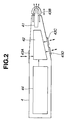
- FIG. 2 is a block diagram showing an arrangement of a designation device.
- the designation device 4 comprises a light emitting element 41 such as a light bulb, a semiconductor laser or an LED element for emitting a light beam 45, a light emission control unit 42 for controlling the emission of light, a plurality of operation switches 43A-43D, and a power source unit 44 which is an electric battery in this embodiment.
- Power source 44 may alternatively be a mains connection or a manually-operated generator.
- Light emission control unit 42 controls the light emitting element 41 to turn ON and OFF at a predetermined cyclic frequency, and may also add a control signal to the emitted light by modulation methods to be described below.
- the alternation may be between two levels (HIGH and LOW) of brightness.
- the frequency of this alternating intensity is preferably high enough to avoid visible "flickering" of the light spot when viewed by the user. References to ON and OFF states should be construed accordingly to include references to HIGH and LOW.
- the control signal modulation applied to the alternating light beam depends on the conditions of the operation switches 43A to 43D.
- the frequency of the control signal modulation should be such as to avoid "flickering".
- the coordinate detection device 1 in Figure 1 detects light emitted from the designation device 4 after the light has passed through the screen 10.
- the device 1 comprises a coordinate detection sensor unit 2, a controller 3 controlling the coordinate detection sensor unit 2 and performing coordinate calculation, a control signal detection sensor (light receiving element) 6, and a signal processing unit 7.
- the coordinate detection device 1 detects a coordinate of a position of a light spot 5 on the screen 10 and a control signal corresponding to a condition of each switch 43A to 43D of the designation device 4.
- the coordinate detection device 1 communicates the detected information to an external device such as a computer 200 via an output means 3A.
- the external device may be a personal computer comprising a processing unit 201 having RAM 202 and ROM 203 memories for storing data and programs etc., input devices such as keyboard 204 and mouse 205, a disk drive 206 for reading and writing data to a removable disk 207, and a display 208.
- a printer 209 may optionally be connected to the computer 200, and a modem 210 may provide for communication via a network.
- the computer 200 connected to the coordinate detection device 1 receives the detected information transmitted from output means 3A analyses a coordinate and a control signal included in the received information and generates a command based on the analysis.
- the computer 200 may execute an operation depending on the command, or may transmit the command to an external device.
- the operation may be an instruction to the display 208, modem 210, printer 209 or memory drive 206.
- the instruction may be to display images or text on display 208, to send to or receive from other devices some information via modem 210, to print out images or text by printer 209 or to store some information to disc 207, which is detachable with computer 200, by memory drive 206.
- the memory 207 may be a floppy disc memory, a compact disc memory or an optical memory etc.
- Computer 200 may identify an icon where the coordinate designates and then generate a command corresponding to the type of icon and the control signal transmitted by the light beam.
- the icon is identified based on a relation between coordinates and command icons stored in a memory within the computer 200.
- computer 200 receives a coordinate transmitted from output means 3A, but when coordinate calculation unit 32 is arranged in computer 200, computer 200 receives the output of AD conversion 31A and is arranged to set the threshold value, select effective difference data and calculate the coordinates.
- the back-projection type display apparatus 8 comprises an illumination optical system and a projection lens.
- the illumination optical system includes an image signal processing unit 81, which is adapted to receive an image signal output from the external device 200 and to provide a control signal to drive a liquid crystal panel 82.
- the display apparatus further comprises a lamp 83, a mirror 84 and a condenser lens 85.
- the back-projection type display apparatus 8 is capable of displaying a desired image on the screen 10.
- the screen 10 has a suitable light diffusion for increasing a visible range of a projection image.
- a light beam emitted by the designation device 4 is also transmitted and diffused at a light spot 5.
- the coordinate detection device 1 receives a part of the diffused light independent of the position of the light spot on the screen and of the direction of the incident light beam 45 from the designation device 4 relative to the plane of the screen 10.
- the coordinate input apparatus is capable of inputting character information and line and image information on the screen 10 by moving the light spot 5 over the screen, and by modulating the light beam emitted by the designation device 4 using the switches 43A to 43D.
- the coordinate information and modulation information associated with the light spot 5 is transmitted to the computer 200 via the output means 3A.
- This information is processed and may influence the image signal sent from the computer 100 to the signal processing unit 81, to display the information by using the projection type display apparatus 8.
- the designation device 4 may thus be used as an information input/output device to move a cursor displayed on the screen, to designate a button displayed on the screen 10 or to perform an input operation by selecting an icon.
- An optical coordinate input apparatus is described in detail below.
- the light emission control unit 42 controls a light emitting element 41 to turn the light ON and OFF (or to alternate the light emission between HIGH and LOW intensity states), and to add a control signal to the light by modulation methods described below.
- the nature of the control signal depends on a condition of the operation switches 43A to 43D.
- a truth table showing the relationship between the switch inputs of the designated device 4 and the control signals is shown in Figure 3.
- Switch A-D corresponds to switches 43A-43D in Figure 2
- "light emission” corresponds to emission of an alternating light beam from element 41, producing a light spot 5
- "pen down” and “pen button” correspond to control signals transmitted by modulating the alternating light beam.
- the switch 43A is arranged at a position convenient for the operator's thumb.
- the switch 43A is pushed, the light beam 45 is emitted.
- the light spot 5 is generated on the screen 10 and a coordinate signal output is started.
- the control signals for pen down and pen button are in the OFF condition. Therefore only a coordinate position on the screen is indicated at output 3A.
- the switches 43C and 43D are arranged at positions convenient for the operator's index finger and middle finger, respectively. When these switches are pushed, then control signals corresponding to pen down and pen button are added to the light beam 45 as shown in Figure 3. Namely, when the switch 43C is pushed, the "pen down" control signal is sent via the light beam 45. Then the display controlling functions, such as to input characters, lines and images, or to select and operate buttons displayed as icons on the screen, become available.
- the designation device 4 is to be used only as a direct input device, i.e. it's not to be used as a pointer but only to be used in contact with the screen, it is not necessary to produce a light beam, and a diffusion light is available as the light source for the designating device. It is then possible to use a lower cost and longer life LED rather than a semiconductor laser.
- the system shown in Figure 1 is a back projection system, namely the structure the display apparatus is positioned behind the screen 10 (on the opposite side of the screen from the operator).
- the image output from the display apparatus is projected onto the screen from behind.
- the light emitted by the designation device 4 reaches the coordinate detection device 1 after passing through the screen 10.
- front type projectors such as that shown in Figure 23, which projects an image output from a display apparatus onto a wall of a room or onto an opaque screen, have become common, and this invention can be used with such a system.
- the structure of the coordinate detection device 1 is similar to that used with the back-projection type system explained above, and consequently its detailed description is omitted here.
- the position of the light has to be detected without the light passing through the screen 110 in the embodiment of the front projection type system.
- the structure of the designation device 140 for use with a front projection display system is described with reference to Figures 23 and 24 below.
- the designation device 140 comprises an elongate telescopic centre section C, at one end of which is a grip part 140a.
- the grip part houses operating switches 143A, 143C and 143D, as well as internal operating components namely a power source 144 and a light emission control unit 142.
- a light emitting source 41 is arranged in a tip portion situated at the other end of the centre section C.
- the tip portion 146 comprises a light emitting element 141, a switch 143B, and a transparent protective cover 147.
- the light emitting element 141 and the cover 147 are so configured that when the switch 143B is placed in contact with the screen 110, light emitted from the light emitting source 141 is directed away from the screen 110.
- the speaker should not stand between the projection type display apparatus and the screen in order to avoid blocking the light from the projection type display apparatus.
- a tool such as a pointer is used to draw attention to an area of the screen.
- the speaker moves to the computer controlling the displayed image to input a control to change the image, or another person is required for inputting control data to the computer when the displayed image on the screen has to be changed.
- the system shown Figures 23 and 24 enables the speaker to add information to the displayed image and input position information of a desired position without approaching the computer.
- the input can work in the same way as a conventional screen mouse, and by clicking on an icon such as a command input button, the user can control the computer without moving and without another person's help.
- the switch 43B of the designating device of Figure 2 is arranged at the distal end of the designation device 4.
- the switch 143B of the designating device of Figure 24 is arranged at the distal end of the designation device 140 (i.e. the end remote from the grip 140a).
- the switches 43B and 143B are both operated by being pressed on the screen 10 or 110.
- the operator grasps the designation device 4 or 140, presses the end or tip of the designation device on to the screen 10 or 110 and the "pen down" control signal is applied to the light beam emitted from the designating device 4 or 140.
- the coordinate detection sensor units 2 detect the position of the light spot 5, and the control signal detection sensor 6 detects the control signal applied to the light beam.
- the control signal detection sensor 6 detects the control signal applied to the light beam.
- the switch 43A or 143A plays a part of a pen button. Pushing the switch 43A without pressing the designating device onto the screen can provide only a position signal, which may be used in the external device to control the position of a screen cursor. In reality, to input characters and images by touching directly on the screen is much better in operation and more accurate than to operate far from the screen.
- This embodiment can realize a spontaneous and comfortable operation in a position close to the screen or a position far from the screen by using four switches as described above and the switches are used according to the situation.
- the light emission controller 42 may be configured to transmit an individual identifying signal such as an ID number as part of the modulation of the light beam 45 or 145, so that two types of designation devices 4 and/or 140, such as a contact designation type and a remote designation type can be used, or so that two or more operators can use designation devices at the same time, or a plurality of designation devices 4 or 140 having a different attributes in colour or line width can be used.
- Software of an externally connected device may be arranged so that attributes of drawing lines in colour or width are made to correspond with lines drawn by a particular device 4 or 140 in accordance with the ID number of that device.
- the line attributes for each device may be set and changed by using a button or menu on the screen.
- the software may be arranged to transmit a change control signal by using an extra operation button arranged on the designation device 4 for that operation.
- a further alternative arrangement is to store in the designation device 4 or the coordinate detection device 1 data corresponding to line attributes etc of each designating device and to transmit this data, rather than the designating device's ID number, to the external device.
- the extra operation button such as described above can be used for another function. For example to flash on and off on a display apparatus, to switch a signal source, to control a video recorder or other device connected either to the external device (the computer 200) or connected directly to the coordinate detection device 1 via an auxiliary output port separate from port 3A. Further, if a pressure detection means is provided for either or both of the switches 43A and 43B (or 143A and 143B), this allows the detection of a writing pressure and the transmission of the writing pressure with the control signal. In this way, various useful signals can be transmitted to the coordinate detection device 1.
- the light emitting starts in accordance with changing to ON condition of either the switch 43A or switch 43B of the designation device 4, and a light emission signal such as the LSG signal shown in Figure 7 is output.
- a header part comprising a comparatively long leader part (LEADER) having a continuous pulse sequence and codes such as a manufacturer ID is output at first.
- the transmission data sequences comprising a pen ID and control signal etc. is output in a predetermined order and format.
- a "1" bit signal is defined by a clock interval in which light is received followed by three clock intervals in which no light is received.
- a "0" bit signal is defined as a clock interval during which the light is received followed by a single clock interval of no light.
- the "1" bit requires twice the interval of "0" bit for transmission (four clock intervals as opposed to two).
- Various data modulation formats are usable. As will be explained below, it is necessary to keep a constant light value average for effective coordinate detection, and for the clock intervals of the control signal modulation to be large enough for PLL tuning.
- 6bit (64) data are modulated to 108 codes within 10 bits length codes in which equal numbers of "1" and "0" bits are present and the number of consecutive "1"s or "0"s is three or less in this embodiment. According to this modulation method, a stable sync signal can be generated easily since an average of voltage is kept constant and the large clock intervals are included.
- the control signals indicative of a "pen down” and "pen button” require 2 bits as described above, but other long data such as an ID code has to be transmitted.
- one block of 24 bits comprising a control signal for the first 2 bits, a contents identification code for the next 2 bits (for example "00" means a writing pressure, "11” means an ID and so on), then a parity signal for the next 2 bits, data for the next 16 bits and a further parity signal for the next 2 bits.
- a signal 40 bits in length is generated.
- a sync code having 10 bits length is added to that.
- the sync code has a pattern with four consecutive 0 codes and five consecutive 1 codes.
- the pattern is changed to an opposite pattern in accordance with whether the end of the last block is 1 or 0.
- the identification of a data word is performed easily, and the position is identified accurately even in the middle of the data sequence. Then decoding can be performed. Therefore the transmission signal has 50 bits length for one block and can transmit a control signal, ID, data and writing pressure, etc..
- the frequency at which the intensity of the light varies (the "first frequency") is set to 60 kHz and the frequency of the clock intervals in the control signal modulation (the “second frequency”) is set to 7.5 kHz which is 1/8 of the first frequency. Since the modulation is performed by the above method, an average of transmission bit rate is 5 kHz which is 2/3 of the second frequency.
- One block has 50 bits. The 24 bits data are transmitted as one block at 100 Hz. Therefore an effective bit rate exclusive parity is 2000 bits /sec. The redundancy is high with this method, but communication can be effected in a simple structure that can avoid incorrect detection and synchronize very easily.
- the signal can be followed even if a short drop out occurs in the signal.
- the presence or absence of a header signal is used to distinguish between a drop out and the quick operations of "pen up" and "double click".
- the Coordinate Detection Device 1 The Coordinate Detection Device 1
- Figure 4 shows an internal arrangement of the coordinate detection device 1.
- the coordinate detection device 1 has a sensitive light receiving element 6 for detecting a luminous energy by using a condensing optical system, and two linear sensors 20X and 20Y for detecting a direction of a light source by using an imaging optical system.
- the linear sensors constitute a coordinate detection sensor unit 2.
- the operation of the coordinate detector is the same, irrespective of whether the back-projection or front projection display device is used.
- the following description will refer to the back-projection embodiment, but it is to be understood that the detection of the position of the light spot is carried out in the same manner in the front projection arrangement.
- the coordinate detection device 1 receives light diffused from the light spot 5 generated on the screen 10 by a light beam from the light emitting element 41 within the designation device 4.
- a controller 3 constitutes a sensor control means 3, an AD conversion unit 31A, a coordinate calculation unit 32 and a communication unit 33.
- Controller 7 (Signal processing unit) constitutes a frequency detection unit 71 and a control signal detection unit 72. The function of each unit will be clear from the description below.
- An imaging lens is attached to-the light receiving element 6 as an imaging optical system ( Figure 1), and detects with high sensitivity a luminous energy of a predetermined wavelength over the entire area of the screen 10. After the detection output is detected by the frequency detection unit 71, a digital signal, which includes data such as a control signal (the signal is added by the light emission control unit 42 of the designation device 4), is decoded in the control signal detection unit 72.
- the operational components of the coordinate detection device 1 are illustrated in Figure 25.
- the apparatus comprises a Central Processing Unit (CPU) 301 for controlling and executing the processing operations, and memory 302 for storing the control programs and various data generated in each operation.
- the control program for executing the operations shown in the flowcharts of Figures 12, 16, 17 and 20 are stored in the memory 302 and the CPU 301 executes the operations based on the control programs. Therefore the operations of the coordinate calculation unit 32, frequency detection unit 71 and control signal detection unit 72 seen in Figure 4 are executed by the CPU 301.
- the programs are preferably stored in the memory 302 before the operation starts, by reading them from a data carrier such as a floppy disk or CDROM or by downloading from an external source via a modem 210 connected to a communications network (see Figure 1).
- Communication interface 303 controls the communication between the apparatus and an external device such as computer 200, an information processing unit, movable device, telephone etc. (not shown).
- the communication interface 303 controls transmitting and receiving of signals and data.
- the signals and data may be received and transmitted through a network such as public communication service, Internet, LAN (Local Area Network) between the apparatus and external devices.
- Sensor 306, sensor control unit 307 and AD converter 308 corresponds to the units 2, 31 and 31A in Figure 4.
- the apparatus comprises a sensor 306, sensor control unit 307 and AD converter 308, but the sensor 306 can be arranged in a separate device from the remaining components.
- the input interface 304 receives signals transmitted from the sensor 306 and sends them to the sensor control unit 307 or AD converter 308, and the output interface 305 transmits a control signal and data from the sensor control unit 307 to the external sensor 306.
- the sensor control unit 307 or AD converter 308 can be arranged in another external device.
- the input interface 304 receives signals and data transmitted from the sensor control unit 307 or AD converter 308 and sends them to other internal units, and the output interface 305 transmits signals and data from other internal units to the sensor control unit 307 or the AD converter 308.
- the operations of the input interface 304 and output interface 305 for communicating between the apparatus and the external devices are controlled by the CPU 301.
- Each unit of the apparatus of Figure 25 is connected with bus 309 then signals and data can be transmitted between any two units.
- the apparatus shown in Figure 25 may include a display device for displaying an image or message showing a condition of operation or input signal and data, and an input device such as a key board or a pointing device for inputting an instruction for controlling the operations.
- Figure 7 is a timing chart describing a decoding operation of a control signal.
- the signal constituted by the bit sequence described above is detected as a light output signal LSG in the light receiving element 6 and detected in the frequency detection unit 71.
- the frequency detection unit 71 is structured to tune with a pulse cycle of the first frequency in the light output signal LSG, and it decodes a modulation signal CMD without influence of the ambient light by using it with an optical filter.
- This detection method is the same as the manner of an infrared remote controller used in broad practice, and is a highly reliable wireless communication method.
- the first frequency is 60 kHz that is a higher frequency than is usually used with infrared remote controllers, so that an incorrect operation should not occur if a conventional infrared remote controller is used simultaneously.
- the first frequency can, however, be in a frequency range of the usual infrared remote controller. In this case, incorrect operation can be avoided by an identification of an ID signal.
- the modulation signal CMD detected by the frequency detection unit 71 is analysed as digital data by the control signal detection unit 72 and the control signals such as "pen down” and "pen button” described above are decoded.
- the decoded control signals are sent to the communication control unit 33.
- the code modulation cycle included in the modulation signal CMD is detected as the second frequency by the sensor control unit 31 and the linear sensor 20X and 20Y. Namely, each unit is reset on the timing of header part shown in Figure 7, after that a signal LCK phase synchronized with a falling edge of the modulation signal CMD is generated. Therefore, the generated signal LCK has a constant cycle and is synchronized with a light luminance of the designation device 4.
- a signal LON is generated to be high when the light spot is present, and low when the designating device projects no light, and a sensor reset signal RCL is triggered by the signal LON is generated from the modulation signal CMD.
- the linear sensors 20X and 20Y are reset while the modulation signal CMD is on a high level and synchronized integration operation is started at the falling edge of the sensor reset signal RCL synchronized with the rising edge of the signal LON.
- the control signal detection unit 72 detects the header part of the signal then confirms a start of input from the designation device 4, and not from another device or noise. It is identified, then the identification signal is transmitted from the communication control unit 33 to the sensor control unit 31, a signal CON showing linear sensors 20X and 20Y operations are effective is set on high level and an operation in the coordinate calculation unit 32 is started.
- Figure 8 shows a timing chart at the end of a series of operations after the light output signal has stopped. If the modulation signal CMD detected from the light output signal LSG keeps low level for a predetermined period or more, the signal LON which shows the presence or absence of the light spot changes to low level and the signal CON which shows sensor operation is effective also changes to low level. The result is that the coordinate output operation of linear sensors 20X and 20Y ends.
- FIG. 5 is a diagram showing an arrangement of the linear sensors 20X and 20Y.
- the images (91X, 91Y) of the light spot 5 are created as lines each falling transversely across a respective linear array of sensors. Each sensor corresponds to a pixel of the array.
- the linear images of the light spot are formed on the sensitive parts (21X, 21Y) of each sensor array by respective cylindrical lenses 90X and 90Y as a imaging optical system. By arranging that the axes of the cylindrical lenses make a right angle exactly, each output has a peak at a pixel corresponding to an X coordinate or a Y coordinate.
- These two sensors are controlled by the sensor control unit 31, the output signal is converted to a digital signal by the A/D conversion unit 31A connected with the sensor control unit 31, and is sent to the coordinate calculation unit 32.
- the coordinate calculation unit 32 calculates an output coordinate value from the digital signal and supplies the result to the control signal detection unit 72.
- the control signal detection unit 72 sends the coordinate value from the coordinate calculation unit 32 to an outside control apparatus (for example computer 200) by a predetermined communication method through the communication control unit 33 with data such as a control signal.
- a mode switch signal is sent from the communication control unit 33 to the sensor control unit 31 and the coordinate calculation unit 32 for an unusual operation such as adjustment (for example a setting of user correction value).
- focus is adjusted so that the linear image of the light spot 5 has a width which is a number of times greater than the width of a pixel in each sensor and the image is shaded off intentionally.
- the image has 15 ⁇ m or less width within all available degree 40° and it is clear that a separated calculation result between pixels makes distortion in this situation.
- a position of lens is adjusted as an image has 30 ⁇ m to 60 ⁇ m more or less in width, very smooth coordinate data can be obtained.
- One of this embodiment's points is to use a CCD having a small number of pixels, and an optical system which gives a linear image covering a suitable number of pixels.
- a coordinate input apparatus which needs a small calculation capability, a small sensor and optical system, and provides reliable detection, high precision and high speed is realized by using that combination.
- a linear sensor 20X for X coordinate detection and a linear sensor for Y coordinate detection are arranged in array and have the same structure. Only linear sensor 20X for X coordinate detection is described below.
- Figure 6 is a block diagram showing the internal arrangement of the linear sensor.
- the sensor array 21 as the light receiving part is constituted by N pixels (64 pixels in this embodiment) and electric charges corresponding to the amount of light received at each pixel are stored in the integrating unit 22.
- the integrating unit 22 has N parts and can be reset by addition of a voltage at gate ICG, allowing an electric shutter operation to be effected.
- the electric charge stored in the integrating unit 22 is transmitted to a storage unit 23 responding to an addition of a pulse voltage at an electrode ST.
- the storage unit 23 has 2 x N parts and stores electric charge separately corresponding to H(high level) and L(low level) of the signal LCK synchronized with a light emitting timing of the designation device 4.
- the stored electric charges are read out by an amplifier 29.
- the amplifier 29 outputs a voltage being in proportion to the stored electric charge amount. In practice, it outputs a difference of electrical charge amount between adjacent stored values, i.e. an amplified amount corresponding to the difference between the electric charge amount of a pixel in the light emission state of the light emitting element 41 and the electric charge amount of that pixel in the light non-emission state, for each of the N pixels.
- Figure 9 is a diagram showing an example of a waveform output from linear sensors 20X and 20Y.
- the vertical axis relates to charge amount, and the horizontal axis to pixel position.
- Waveform B shows a signal read out in the light emission state of the light emitting element 41
- waveform A shows a waveform in light non-emission state, i.e. it shows only the ambient light waveform.
- a maximum value of B-A waveform shown in Figure 9 is also defined as the PEAK value. If a storage period for the sensor function against light is increased, i.e. if charge is allowed to build up by adding together charge values for successive clock intervals, the PEAK value is increased correspondingly to the period increase. In other words, if a cycle period of the signal LCK is used as a unit storage period, the number of storage times n is defined by using the unit storage period and the number of storage times n is increased, then the PEAK value is increased. By increasing the detection time until the PEAK value reaches a predetermined value TH1, an output waveform having stable quality at all times can be obtained.
- the sensor is provided with a skim unit 28 having a skim function.
- the skim unit 28 senses the signal level in the light non-emitting state (i.e. the ambient light), and if the signal level exceeds a predetermined value (the level is shown by a dot and a chain line in Figure 10) at an n-th clock interval An as shown in Figure 10, a predetermined value of electrical charge is removed from the stored electrical charge in each pixel. Therefore the waveform An+1 is obtained at the next (n+1th) clock interval.
- Figure 11 shows a flow chart of the operation for controlling the linear sensors 20X and 20Y.
- the sensor control unit 31 starts a sensor control operation in step S101 and monitors a signal CON in step S102. If the signal CON changes to high level, a counter pon is set to 1 and sets the number of storage times n to 0 in step S103 and judges whether a PEAK value (peak level) of sensor output is larger than a predetermined value TH1 or not in step S104.
- step S105 it is determined whether the number of storage times n is more than a predetermined number of times n0. If it is not, the flow shifts to step S106 and increments the number of storage times n by one and returns to step S104.
- step S107 after the PEAK value becomes bigger than TH1 or the number of storage times n is more than a limit value n0 then the integral operation stops.
- a coordinate calculation operation by the coordinate calculation unit 32 then starts. The coordinate calculation is described below.
- step S108 After that, if the counter n is over a second predetermined number of times n1 in a loop of step S108 and step S109, the integral stop signal RON changes to low level, at the same time the sensor reset signal RCL is in high level for a number (two in Figure 8) of cycle periods of the signal LCK(step S110). After that the flow shifts to step S112 and the operation is repeated while the signal CON is in high level then the coordinate calculation is done in each cycle controlled by the predetermined number of times n1.
- Step S111 is for keeping a condition against at least one signal CON dropping due to the influence of dust. If the signal CON is at low level for two consecutive cycles, the flow shifts from step S102 to step S113, the counter pon is reset to 0 and returns to step S101 after a sync waiting condition has made.
- This dropout countermeasure operation can be longer than one cycle, and it is also removed if ambient background is negligible. If this cycle changes to a natural number of times the cycle of the data block described above, it corresponds to the timing of sync code and not the signal CON but if a sync code detection signal is used similar operation can be realized.
- the same effect can be obtained by using a natural number times of the data block as one cycle, synchronizing the timing with the sync code timing and using a detection signal of the sync code in place of the signal CON.
- the light of the designation device 4 reaching the coordinate detection device 1 changes, in response to a consumption of an electric source (changing electric battery voltage) arranged in the designation device 4, and also in dependence on the orientation of the designation device 4.
- an electric source changing electric battery voltage
- the change of luminous energy input to the sensor varies depending on the relative positions of the light spot and the designation device 4.
- the number of integration times is varied automatically to compensate for this effect, and a stable output signal can be obtained at all times. This brings the result that reliable coordinate detection can be obtained. If the beam of the laser pointer is pointed directly at the sensor, then a strong light is input but even in this case, the stable coordinate detection can be obtained clearly.
- the numbers of integral times n0 and n1 shown in Figure 11 can be adjusted, depending on whether the active designation device is a pen or a pointer.
- the determination as to whether the designation device is a pen or a pointer can be realized based on the ID signal supplied by the respective designation device when active. This allows high speed sampling to be used when the pen is active and low speed sampling to be used for the pointer. In practice, a delicate drawing operation such as character input can not be done by the pointer. Better use of the pointer can be obtained in smooth line drawing operation provided by low sampling rates.
- a high frequency control signal is added to the flashing light and the integral operation timing is controlled by the predetermined cycle decode signal obtained by the frequency detection of the carrier. Then the designation device and the image input unit are synchronized in a wireless condition and a useful coordinate input device can be realized.
- the use of a laser beam allows a user far from the screen to operate the display easily.
- the integral control unit steps the integral operation responding with a detection that the peak level in the difference signal from the integrating unit is over the predetermined level, the signal of light spot image having a stable level can be generated even if the luminous energy has changed. Therefore, stable and reliable detection coordinate calculation results can be obtained at all time.
- the method for keeping the quality constantly independent on the amount of luminous energy input to the sensor was described above, but one problem is risen.
- the output signal (difference signal from amplifier 29) for each of the linear sensors 20X and 20Y as above is sent to the coordinate calculation unit 32 after conversion to a digital signal by the AD conversion unit 31A arranged in the sensor control means 31, and coordinate value is calculated.
- the coordinate on sensor (X1,Y1) corresponding to each output data of X coordinate and Y coordinate are obtained in the coordinate value calculation. Only the calculation related to X coordinate will be described below, since the calculations related to the X coordinate and the Y coordinate are similar.
- Figure 12 is a flowchart showing coordinate calculation processing according to a first embodiment.
- the coordinate calculation processing starts, and the variable cont is set to 0 in step S201 at first.
- the variable cont is used in standard point setting mode (as below).
- the difference data Dx(n) is got in step S202 and stored in a buffer.
- the Dx(n) data for each pixel is compared with a predetermined threshold value V and data value Ex(n) which is an excess value being over the threshold value is obtained in step S203 for each pixel.
- the coordinate X1 on the sensor is calculated by using the Ex(n) data from step S204.
- a centroid position of output data is used in this embodiment but alternative calculation methods such as peak value calculation, for example by differentiation, can be used.
- the mode of coordinate calculation processing is decided in step S205.
- a predetermined reference value must be decided before a calculation for a coordinate based on a centroid position X1 of output data, and the predetermined reference value calculation (reference point setting mode) is described below.
- the matter about X direction is described.
- the light spot from the designation device 4 is sequentially positioned at two setting points on the screen 10, which have known X coordinate and Y coordinate values ⁇ 0, ⁇ 0 and ⁇ 1, ⁇ 1, and the steps S202-S204 are operated to obtain two respective centroid values X1 0 , and X1 1 on the X direction sensor.
- the centroid values X1 0 and X1 1 and the known coordinate values ⁇ 0 and ⁇ 1 are stored in step S210.
- the operation is repeated twice to obtain signals X1 0 and X1 1 corresponding to positions ⁇ 0 and ⁇ 1.
- the X coordinate of the coordinate input point is calculated in step S206 by using the values (X1 0 , X1 1 , ⁇ 0 and ⁇ 1) stored in step S210, in accordance with the formula or S210. If necessary, a coordinate correction, for example a distortion correction by software calculation to compensate for an aberration of the optical lens, is done and the corrected coordinate value is output from step S207 because higher level coordinate input device can be supplied.
- a coordinate correction for example a distortion correction by software calculation to compensate for an aberration of the optical lens
- the Y coordinate calculation is performed in the same way, using the values ⁇ 0 and ⁇ 1 instead of ⁇ 0 and ⁇ 1.
- calculated and optionally calculated coordinates can be output in real time or the coordinates can be thinned out responding to the purpose, for example one output out of every ten calculated coordinates actually being used.
- the choice is important in the cases below.
- the user's hand stability differs depending on whether the designation device 4 is used as a pen or as a pointer.
- the designation device 4 When as a pointer to project a spot onto the screen from afar, the light spot trembles on the screen, and this trembling should be repressed for better use.
- tracking of the light spot is required to be as accurate and as quick as possible. Especially if a character is written, quick operation is necessary for accurate input.
- ID Since ID is transmitted by using control signals in the embodiment of Figure 2, it can be determined whether the device is used as a pointer or a pen by detecting whether the end switch 43B is pressed or not.
- a current output coordinate (X,Y) may be obtained by extrapolation from the previous coordinate values (x-1,Y-1) and the coordinate values (X-2,Y-2) preceding them. A useful structure having little error is realized.
- the movement mean is used in this embodiment, but other methods wherein the absolute value of the difference in position is nonlinearly compressed according to its size, or wherein a difference with a calculated value obtained by a movement mean has been nonlinear compressed can be used as functions used in the smoothing process. Switching the smoothing operation to strong when the designating device 4 is used as a pointer or to weak when it is not used a pointer may be effected by the control signal to optimise use conditions in both cases.
- the available time to finish the calculations is 10 msec if the coordinate sampling frequency is 100 Hz as below, then the source data which has 64 pixels x 2(for x and y coordinates, respectively) x AD conversion unit 8 bits is very little. Further a low speed 8 bits 1 tip micro processor can process the data since convergence calculation is not necessary. This is effective for low cost, easy specification changing, short period development and easy development of derived products. Especially since the development of a special LSI for high speed image processing is unnecessary, the development cost and period is reduced. It has been described above to use an area sensor as an example.
- the data signal showing the coordinate value (X, Y) obtained by calculating operation is sent from the coordinate calculation unit 32 to the communication control unit 33.
- the communication control unit 33 inputs the data signal and the control signal from the control signal detection unit 72.
- the data signal and the control signal are converted to a communication signal having a predetermined form and transmitted to a display control device outside. Therefore the cursor, menu, character and line on the screen can be operated.
- the sensor having 64 pixels is used, sufficient detection accuracy is achieved, and the sensor and optical system are low in size and cost, and the calculation circuitry is also very small in the coordinate input apparatus.
- the linear sensor 20 wherein a plurality of photoelectric conversion elements arranged on a line is described above, but another sensor comprising a two dimensional array of photoelectric conversion elements may be used for coordinate detection.
- condensor lenses for making a shaded off image are used instead of cylindrical lenses 90X and 90Y.
- Output signals of the photoelectric conversion elements are stored in memory, with the 2 dimensional position data of the respective photoelectric conversion element. The pixel having the maximum difference signal is found, and its position coordinates are obtained, based on the stored signals.
- the threshold value may be calculated based on the difference signals corresponding to pixels positioned on or within a circle which has a centre at the peak pixel, or on the basis of difference value from pixels in or on another closed curve surrounding the peak pixel or in a region surrounding the peak pixel.
- the signal of the light spot flashing on and off in a predetermined cycle from the designation device 4 is integrated separately in each state, light emitting state and light non-emitting state, and obtain the difference signals for achieving an accurate determination of the position of the peak pixel in this embodiment.
- This enables an apparatus with high accuracy and high detection coordinate value reliability can be obtained, the influence of ambient light is reduced and the apparatus is small, light and low cost.
- the difference data Dx(n) are compared to a fixed threshold THI corresponding to a voltage value V in the coordinate calculation operation shown in Figure 12. Therefore, if the PEAK value of Dx (n) does not exceed TH1 after the integration has been done n0 times in the operation of Figure 11, namely if the luminous energy is not enough, the accuracy of coordinate detection is decreased. If n0 is increased so as to achieve enough luminous energy, it results in decreased detection speed.
- This second embodiment takes measures to overcome this problem.
- the light from the light emitting element 41 arranged in the designation device 4 can be detected as a stable signal by the integral operation of sensor 20. But if the luminous energy reaching to the sensor 20 is decreased, the number of times the integration operation must be repeated to bring a peak level of the detection signal to a predetermined level is increased and the coordinate calculation sampling rate (the number of positions can be calculated every unit time) is decreased. At least a tens of points per second sampling rate, if possible one hundred points or more per second, is expected to recreate a user's writing accurately with the coordinate input device. If an LED is used as the light emitting element 41 in the arrangement of the embodiment of Figure 2, only few percent of the luminous energy emitted by the LED can reach sensor 20 in the worst case.
- accurate coordinates can be detected even if the peak value of the signal output from the sensor doesn't reach TH1 when the predetermined integral operation, for example the number of integral times n0 and n1 are set to achieve 10m/sec as a maximum integral time for one sample in order to achieve one hundred points per second as coordinate sampling rate, is completed.
- Figure 13 is a diagram showing an output level of each pixel in a sensor.
- the effective data is determined by using threshold level V. If the threshold level V is set to have a sufficient margin from noise level in a condition the output signal is obtained enough, then a stable coordinate can be calculated without the influence of noise. To set a lower threshold level is better since a decrease of detection signal level responding to a lack of luminous energy may occur depending to a real use condition as above. For example, a coordinate can be calculated with a smaller level of output signal if the threshold level is set to Vlow, but the calculation accuracy is decreased because the influence of noise becomes strong.
- Figure 16 is a flowchart showing a coordinate calculation processing according to this embodiment. The coordinate calculation excluding an influence of noise by decreasing the threshold level is explained in the processing in Figure 16.
- the values of Dx(n) are compared with the threshold value in step S311 and Ex(n) is stored for each pixel in a buffer.
- the operation in the steps S301, S302 and S311 is the same as the steps S201 - S203 described above with reference to Figure 12.
- step S303 a pixel where the output signal n peak is greatest is detected in step S303.
- the coordinate on the sensor X1 is calculated according to the equation below by using the maximum output signal n peak and data of m adjacent pixels on either side of the pixel having output value n peak in step S304. Therefore the number of pixels used is 2m+1.
- the coordinate calculation is effected using the formula: set out in step S304.
- FIG. 15 illustrates the accuracy of the calculation method of the prior art (left hand column) wherein a centroid is calculated using all the pixel difference signals, and the method of the second embodiment using various volumes of m pixels (i.e. differing numbers of pixels on either side of the peak pixel) to calculate the centroid.
- the actual coordinate position of the light spot and a detected coordinate at that point are compared and a difference, namely coordinate calculation accuracy, obtained for each point in an array of ten thousand points over the screen area.
- the calculation methods and conditions are shown along the horizontal axis and the calculated coordinate accuracy is shown on the vertical axis.
- Max means a maximum value of the calculated differences at the ten thousand points and the precision means a value Avg+3 ⁇ obtained based on a mean value Avg and a standard deviation " ⁇ " of the distribution of the obtained differences in Figure 15.
- the threshold voltage is set 0.75V and the coordinate is calculated according to the operation shown in Figure 12, then not only is Max of the accuracy decreased badly but also there are some areas where coordinates can not be calculated caused by a lack of luminous energy in the figure.
- the accuracy of coordinate calculation comes to be high at higher threshold levels but the uncalculatable coordinate area expands. If the value m is set at about 4, then by using the calculation method shown in Figure 16, the coordinate calculation can be done in all areas and a good enough calculation result can be obtained.
- Figure 17 is a flowchart showing a coordinate calculation processing according to the third embodiment.
- a variable cont is set to 0 for initializing in step S401, and difference data Dx(n) corresponding to a difference signal at each coordinate input device is read out and stored in the buffer in step S402.
- a pixel n peak where output signal becomes maximum is detected in step S403, and m-th pixels in each direction forward and backward from the pixel n peak are selected and the signal levels of both selected pixels Dx(n peak -m) and Dx(n peak +m) are compared in step S411.
- the smaller of the signal levels is set as a threshold value based on the comparison, and the output signals of each of the pixels are compared with the threshold value in step S413 or step S414.
- step S415. the effective pixels determination is explained. If data Ex(n) for pixel n derived by the operation above is positive, it is clear that the signal is over the threshold level is output at pixel n. But since the set threshold level is a changeable threshold value changed with the signal outputs from pixels on either side of the peak value, the set level can be a noise level in the weak luminous energy condition. If a noise signal is outputted at a pixel far enough from the pixel n peak , it is calculated as a moment (a term of nEx(n)) even if the signal component is small. Therefore the error is not a little effective.
- Ex(n) is positive for a pixel n
- only output signals from pixels in a series having consecutive pixel numbers and including the maximum pixel n peak are determined as effective pixels and the minimum value n min and the maximum value n max of the pixel numbers (n min ⁇ n peak ⁇ n max ) of pixels being used in the calculation are selected in step S415.
- the selected effective data are shown in Figure 14(B).
- the threshold value is changeable and the number of pixels used in this calculation is changeable, however, both are fixed in the operation of Figure 16.
- the centroid position X1 is calculated based on the equation below by using only the effective pixels selected in step S415, namely the pixels whose numbers lie between n min and n max in step S404.
- steps S405 - S410 are the same as the steps S205 - S210 above and their description is omitted here. Now, an effect obtained by the centroid calculation is described.
- Figure 18 and Figure 19 show output results examples of coordinate calculation precision in a part of coordinate input apparatus (40x40mm) having a 1200x900mm coordinate input effective area size.
- Z axis shows a difference between Y coordinate value outputted by the coordinate input apparatus and the Y coordinate value corresponding to the real input position in the figure. Therefore, where the difference is being about 0, the accuracy of the coordinate input apparatus is very high.
- Figure 18 shows the result of the coordinate calculations made in accordance with the operation shown in the flowchart of Figure 16.
- Figure 19 shows the result of the coordinate calculation accordance with the flowchart in Figure 17.
- the measurement error of the calculation method of Figure 16 is approximately 10mm, while the error of the calculation method of Figure 17 is better, decreased to about 2-2.5mm. Also the step effect shown in Figure 15 has not been generated and the distribution of error is smooth. It means that the calculation method of Figure 17 brings better detection in the coordinate input apparatus than the calculation method of Figure 16 and it's clear that the coordinate input apparatus can obtain a high accuracy and a high detection.
- the smaller one of m-th pixels spaced in each direction backward and forward from the pixel n peak having the maximum difference data is selected as a threshold value used for the effective pixel extraction in step S415 in the above embodiment.
- the value of the threshold may be set to be the bigger of Dx(n peak + m) and Dx(n peak -m) in the above threshold value setting stage, and then a higher signal level is selected as the threshold level.
- the threshold value can be determined by for example calculating the means of the 2m+1 values of difference data corresponding to the pixel n peak having the maximum difference data and next m pixels in each direction backward and forward from that pixel, and setting the threshold to this mean value or to a multiple or submultiple thereof.
- the difference signal is calculated by using the integral calculation of signal, which is a flashing light having a predetermined cycle from the designation device 4, separately in light emission state and in light non-emission state, and the pixel having the maximum difference signal (the pixel number n peak ) is detected, the threshold value for deciding the effectiveness of each pixel is set by using the m-th pixels in each direction backward and forward from the detected pixel n peak or 2m+1 pixels corresponding to m pixels in each direction backward and forward of the detected pixel.
- the effective pixels are selected by using the set threshold value and the coordinate is calculated by using the output data of the selected pixels. Therefore a coordinate input apparatus having high accuracy and high detection reliability can be obtained.
- the determination provides higher accuracy and reliability in coordinate detection. If the products using the sensor are manufactured in quantity, the differences between products and their parts should be considered. Especially, the output voltage when no light reaches the sensor, namely output voltage in dark condition, is a problem.
- the output voltage in dark condition usually varies by plus and minus dozens of % from the nominal value, due to manufacturing tolerances. The distribution is from about 0.7 V to about 1.3 V depending on the difference between each product if the electric source voltage is 5 V and it is assumed that the nominal output voltage in dark condition is 1 V.
- the threshold level must be set at 1.3 V or higher, but in this case, a situation that a product having a output voltage in dark condition of 0.7 V is operated at a threshold voltage of 1.3 V may be occur. Namely the coordinate can not be calculated when the luminous energy is weak and only the peak level reaches 1.3 V. Contrary to that, the confidence of coordinate calculation is low and a higher threshold value must be set since the threshold value set at 1.3 V provides no margin against the noise for components in the product having an output level in dark condition of 1.3 V. Therefore, if the product tolerance is considered, the setting of the threshold level depending on parts tolerances is necessary, and the need for adjustment of every product increases costs.
- the mean of the output signals from all of the pixels (64 pixels) is calculated and the mean value is added to a predetermined offset amount Voff to define a first threshold value Vth1 (step S 503).
- the first threshold value is used for determining the effectiveness of output signals (See Figure 13(B)). Namely, Vth1 can be changed in dependance on the luminous energy input to the sensor namely the signal level and on the output voltage in dark condition, then the product's tolerance of each sensor is considered and the best threshold level is set automatically.
- a pixel n peak having a maximum value of the difference data Dx(n) is detected in step S504, and Dx(n peak -m) and Dx(n peak +m) which are output values of the m-th pixels in each direction forward and backward from the pixel n peak are obtained and these values are compared in step S505.
- a second threshold value Vth2 is set based on the comparison result in each of steps S506 and S507.
- the smaller signal level is set as the threshold level in this embodiment, the larger value may be set as Vth2 so that a higher signal level is set as the threshold level.
- step S508 the first threshold level Vthl and the second threshold level Vth2 are compared in step S508. If the second threshold level Vth2 is bigger than the first threshold level Vth1 then it can be concluded that sufficient light is incident on the sensors for a coordinate calculation to proceed, and the coordinate calculation is executed. However if Vth2 is smaller than Vth1, the necessary amount of light to detect coordinate values is not present, and the operation stops and the flow returns to step S501.
- the Dx(n) of each pixel is compared with the second threshold value Vth2 in step S509 and Ex(n) is stored in a buffer. Next only the series of consecutive pixels exceeding threshold Vth2 and including the peak pixel number n peak are selected in step S510 and the coordinate on the sensor X1 is calculated. Where operations correspond to steps in earlier methods corresponding numbering is used and the description is omitted.
- the effective pixels determined in step S510 of this embodiment are shown in Figure 21C. Since the second threshold value Vth2 has been set at Dx(n peak -m) (the value of the n peak -m pixel), the output value of not only n peak +m pixel but also n peak +m+1 pixel in the case of the Figure is used for the coordinate calculation as an effective pixel.
- the first and second threshold values are changeable and the number of pixels used in calculation is changeable, however, both are fixed in the operation of Figure 16.
- Figure 22 shows the coordinate calculation precision of a part (40x40mm) in a coordinate input apparatus having a 1200x900mm coordinate input effective area size in the case of this embodiment.
- the distribution of error is smooth, then the calculation of Figure 20 is better detection in the coordinate input apparatus is shown, and the coordinate input apparatus can obtain a high accuracy and a high detection by the calculation.
- the coordinate input method and devices of the invention can be embodied in one or more parts of a system constituted by a plurality of devices (for example host computer, interface device, reader, printer and so on) and in a single device (for example copy machine, facsimile machine and so on).
Abstract
Description
- The present invention relates to a method and apparatus for inputting position information such as coordinate data particularly for use with a large screen display system. In detail, the present invention relates to a position information input apparatus and method for generating position information such as a coordinate expressing a position designated on a display screen by an operator. The operator may use a designation device for designating the position. The input position information can be used for controlling an externally connected computer, or for writing characters and graphics.
- Some of the prior coordinate input devices sense a light spot on the screen by using a CCD area sensor or linear sensor. The devices calculate and output coordinate values by performing an image processing using centroid coordinates, pattern matching etc.. Some of the prior coordinate input devices use position detection elements (an analogue device for obtaining an output voltage corresponding to a position of spot) called PSD (Position Sensitive Detector).
- For example, Japanese Patent Publication No. 7-76902 discloses an apparatus which senses a light spot of a parallel beam of visible light using a video camera, and calculates coordinate values, and the apparatus simultaneously sends and receives a control signal by infrared diffusion light. Japanese Laid-Open Patent Application No. 6-274266 discloses an apparatus which detects a coordinate value by a linear CCD sensor and a special optical mask. On the other hand, Japanese Patent No. 2503182 discloses a structure of an apparatus using PSD and a correction method for outputting a coordinate value from the apparatus.
- Nowadays, the brightness of large screen displays has improved and they can be used satisfactorily even in a brightly illuminated environment, and the display is expected to be in great demand. A coordinate input apparatus must be more tolerant to ambient light for use in such an environment together with the large screen display. The use of devices using an infrared light as a wireless communication unit is increasing recently. Since levels of infrared light and visible light are increasing in ambient light, it is an important feature for the apparatus to have a high tolerance to ambient light.
- However, as is disclosed in Japanese Patent Publication No.7-76902 and Japanese Laid-Open Patent Application No.6-274266, ambient light is only controlled by an optical filter in the apparatus using a prior-art CCD sensor. To the contrary, as is disclosed in Patent No. 2503182, an effect of the ambient light is controlled by synchronized detection of frequency-modulated light intensity in the apparatus using PSD. The apparatus with an optical filter achieves higher tolerance to ambient light.
- The brightness and resolution of large screen displays are increasing. The resolving power in a coordinate input apparatus must also be increased, but this is difficult to achieve in an apparatus using PSD having high tolerance to ambient light. This is because a dynamic range of sensor output voltage corresponds to a range of input area exactly, then the apparatus must have at least 60db or higher S/N ratio to achieve a resolving power or detection accuracy of 1mm. As is disclosed in Japanese Patent No. 2503182, since a digital correction of linear error is necessary, a high precision analogue circuit, a multi bit AD converter and an arithmetic circuit are required. Since the S/N ratio of the sensor output signal depends on luminous energy and sharpness of the light spot, not only control of the ambient light but also a bright high precision optical system are required for producing a light spot. Accordingly, the apparatus increases in cost and size.
- However Patent Publication No. 7-76902 discloses a method using a plurality of video cameras simultaneously as a method for increasing a resolving power by using a CCD sensor. Such a method makes an apparatus increased in cost and size, and if a video camera having many pixels is used in the apparatus, it increases the apparatus' cost and size more than using a plurality of video cameras, and an artificially high resolving power realized in real time operation by performing an image processing also increases the apparatus' cost and size because high speed image processing is required.
- Japanese Laid-Open Patent Application No. 6-274266 discloses a high resolving power realized by using a special optical mask and signal processing. The resolving power can be increased if the ambient light is weak and high S/N ratio is ensured. In practice, a linear sensor images a line, the ambient light has more effect on a line image in this situation because the line image can't be separated from ambient light within a plane, in contrast to a situation in which an area sensor images dots. For this reason, the apparatus is able to be used only in a special environment having a low level of ambient light.
- Generally the optical elements like CCD etc. are mass produced by semi-conductor processes, but the various features such as optic-electric conversion efficiency etc. differ widely depending on the product environment, the product condition and product lot etc.. For example a difference of about plus and minus 30 % in the optic-electric conversion efficiency is possible as a parts tolerance. When a CCD is worked at an electric source voltage of 5V, then if the nominal value of CCD output voltage in a dark condition is about 1.5V, the actual value for a particular device may be from about 1.0 to 2.0 V (about plus and minus 30%) due to the acceptable parts tolerance. Therefore the threshold value must be set at 2.0V or more when determination of a light output is obtained by comparing the output with a fixed threshold voltage, but elements at the limits of the tolerance range will be unable to detect satisfactorily and the yield is thus decreased, in a structure which receives only low levels of light (namely CCD output is small). To adjust individually the threshold value set in each CCD described above can raise the light sensitivity, but assembly steps are increased and the cost goes up since an adjustment assembly is required.
- The present invention aims to solve the above problem of the prior art, and one aspect of this invention is to control the effect of the ambient light and to provide a coordinate input apparatus and method having a high resolving power and a high precision.
- Another aspect of this invention is to provide a small size and low cost coordinate input apparatus and method.
- Embodiments of the invention will now be described in detail with reference to the accompanying drawings, in which:
- Figure 1 is a schematic block diagram showing an arrangement of an optical coordinate input apparatus according to the embodiment;
- Figure 2 is a block diagram showing an arrangement of a designation device;
- Figure 3 is a truth table showing a relationship between the switch inputs and control outputs of the device of Figure 2;
- Figure 4 is a block diagram showing a schematic arrangement of the coordinate detection device of Figure 1;
- Figure 5 is a schematic diagram showing a physical
arrangement of
linear sensors - Figure 6 is a block diagram showing an internal arrangement of a linear sensor for X or Y coordinate detection;
- Figure 7 is a timing chart of a control signal decoding operation;
- Figure 8 is a timing chart at the end of a series of operations for decoding a control signal from an output signal of a light reception element;
- Figure 9 is a waveform diagram showing an example of a waveform output from a linear sensor for X or Y coordinate detection;
- Figure 10 is a waveform diagram showing a skim operation in a linear sensor;
- Figure 11 is a flowchart showing a sequence of operations for controlling a linear sensor;
- Figure 12 is a flowchart showing coordinate calculation processing according to a first embodiment;
- Figure 13 is a diagram showing an example of the outputs of the elements of a linear CCD sensor;
- Figures 14A and 14B are diagrams showing examples of the elements of a linear CCD sensor, Figure 14A illustrating setting a threshold value, and Figure 14B showing an extraction of effective pixels;
- Figure 15 is a diagram showing a coordinate calculation precision of each calculation method;
- Figure 16 is a flowchart showing a coordinate calculation processing according to a second embodiment;
- Figure 17 is a flowchart showing a coordinate calculation processing according to a third embodiment;
- Figure 18 is a diagram showing the relationship between coordinate calculation precision and XY position, using the calculation processing of the second embodiment;
- Figure 19 is a diagram showing the relationship between coordinate calculation precision and XY position, using the calculation processing of the third embodiment;
- Figure 20 is a flowchart showing a coordinate calculation processing according to the fourth embodiment;
- Figures 21A to 21C are diagrams showing examples of modes of selection of effective pixels;
- Figure 22 is a diagram showing the relationship between coordinate calculation precision and XY position, using the calculation processing of the fourth embodiment;
- Figure 23 is a schematic diagram showing an arrangement for a front-projection display system;
- Figure 24 is a diagram showing a designation device for use in the front-projection display system of Figure 23;
- Figure 25 is a block diagram illustrating the operational components of the coordinate input apparatus.
-
- Referring now to the Figures, Figure 1 is a schematic block diagram showing an arrangement of an optical coordinate input apparatus according to a first embodiment. As Figure 1 shows, the apparatus comprises a
designation device 4 for forming a light spot on ascreen 10 as a coordinate input plane, and acoordinate detection device 1 for detecting position coordinates and optionally other parameters associated with alight spot 5 on thescreen 10. In Figure 1 a back-projection-type display apparatus 8 etc. for displaying image or position information and the like is shown. The back-projectiontype display apparatus 8 functions as an output apparatus. - Figure 2 is a block diagram showing an arrangement of a designation device. The
designation device 4 comprises alight emitting element 41 such as a light bulb, a semiconductor laser or an LED element for emitting alight beam 45, a lightemission control unit 42 for controlling the emission of light, a plurality of operation switches 43A-43D, and apower source unit 44 which is an electric battery in this embodiment.Power source 44 may alternatively be a mains connection or a manually-operated generator. - Light
emission control unit 42 controls thelight emitting element 41 to turn ON and OFF at a predetermined cyclic frequency, and may also add a control signal to the emitted light by modulation methods to be described below. As an alternative to alternating the light emission between ON and OFF states, the alternation may be between two levels (HIGH and LOW) of brightness. The frequency of this alternating intensity is preferably high enough to avoid visible "flickering" of the light spot when viewed by the user. References to ON and OFF states should be construed accordingly to include references to HIGH and LOW. The control signal modulation applied to the alternating light beam depends on the conditions of the operation switches 43A to 43D. The frequency of the control signal modulation should be such as to avoid "flickering". Although the designation device is shown as having fourswitches 43A to 43D, other numbers and dispositions of switches are possible. - The coordinate
detection device 1 in Figure 1 detects light emitted from thedesignation device 4 after the light has passed through thescreen 10. Thedevice 1 comprises a coordinatedetection sensor unit 2, acontroller 3 controlling the coordinatedetection sensor unit 2 and performing coordinate calculation, a control signal detection sensor (light receiving element) 6, and asignal processing unit 7. - The coordinate
detection device 1 detects a coordinate of a position of alight spot 5 on thescreen 10 and a control signal corresponding to a condition of eachswitch 43A to 43D of thedesignation device 4. The coordinatedetection device 1 communicates the detected information to an external device such as acomputer 200 via an output means 3A. The external device may be a personal computer comprising aprocessing unit 201 havingRAM 202 andROM 203 memories for storing data and programs etc., input devices such askeyboard 204 andmouse 205, adisk drive 206 for reading and writing data to aremovable disk 207, and adisplay 208. Aprinter 209 may optionally be connected to thecomputer 200, and amodem 210 may provide for communication via a network. - The
computer 200 connected to the coordinatedetection device 1 receives the detected information transmitted from output means 3A analyses a coordinate and a control signal included in the received information and generates a command based on the analysis. Thecomputer 200 may execute an operation depending on the command, or may transmit the command to an external device. The operation may be an instruction to thedisplay 208,modem 210,printer 209 ormemory drive 206. The instruction may be to display images or text ondisplay 208, to send to or receive from other devices some information viamodem 210, to print out images or text byprinter 209 or to store some information todisc 207, which is detachable withcomputer 200, bymemory drive 206. Thememory 207 may be a floppy disc memory, a compact disc memory or an optical memory etc. -
Computer 200 may identify an icon where the coordinate designates and then generate a command corresponding to the type of icon and the control signal transmitted by the light beam. The icon is identified based on a relation between coordinates and command icons stored in a memory within thecomputer 200. - In the above,
computer 200 receives a coordinate transmitted from output means 3A, but when coordinatecalculation unit 32 is arranged incomputer 200,computer 200 receives the output ofAD conversion 31A and is arranged to set the threshold value, select effective difference data and calculate the coordinates. - The back-projection
type display apparatus 8 comprises an illumination optical system and a projection lens. The illumination optical system includes an imagesignal processing unit 81, which is adapted to receive an image signal output from theexternal device 200 and to provide a control signal to drive aliquid crystal panel 82. The display apparatus further comprises alamp 83, amirror 84 and acondenser lens 85. The back-projectiontype display apparatus 8 is capable of displaying a desired image on thescreen 10. Thescreen 10 has a suitable light diffusion for increasing a visible range of a projection image. A light beam emitted by thedesignation device 4 is also transmitted and diffused at alight spot 5. The coordinatedetection device 1 receives a part of the diffused light independent of the position of the light spot on the screen and of the direction of theincident light beam 45 from thedesignation device 4 relative to the plane of thescreen 10. - The coordinate input apparatus according to this embodiment is capable of inputting character information and line and image information on the
screen 10 by moving thelight spot 5 over the screen, and by modulating the light beam emitted by thedesignation device 4 using theswitches 43A to 43D. The coordinate information and modulation information associated with thelight spot 5 is transmitted to thecomputer 200 via the output means 3A. This information is processed and may influence the image signal sent from thecomputer 100 to thesignal processing unit 81, to display the information by using the projectiontype display apparatus 8. Thedesignation device 4 may thus be used as an information input/output device to move a cursor displayed on the screen, to designate a button displayed on thescreen 10 or to perform an input operation by selecting an icon. An optical coordinate input apparatus according to this embodiment is described in detail below. - The light
emission control unit 42 controls alight emitting element 41 to turn the light ON and OFF (or to alternate the light emission between HIGH and LOW intensity states), and to add a control signal to the light by modulation methods described below. The nature of the control signal depends on a condition of the operation switches 43A to 43D. A truth table showing the relationship between the switch inputs of the designateddevice 4 and the control signals is shown in Figure 3. - In Figure 3, Switch A-D corresponds to
switches 43A-43D in Figure 2, "light emission" corresponds to emission of an alternating light beam fromelement 41, producing alight spot 5, while "pen down" and "pen button" correspond to control signals transmitted by modulating the alternating light beam. - An operator grasps the
designation device 4 and points it at thescreen 10. Theswitch 43A is arranged at a position convenient for the operator's thumb. When theswitch 43A is pushed, thelight beam 45 is emitted. Thelight spot 5 is generated on thescreen 10 and a coordinate signal output is started. In this situation, the control signals for pen down and pen button are in the OFF condition. Therefore only a coordinate position on the screen is indicated at output 3A. - The
switches light beam 45 as shown in Figure 3. Namely, when theswitch 43C is pushed, the "pen down" control signal is sent via thelight beam 45. Then the display controlling functions, such as to input characters, lines and images, or to select and operate buttons displayed as icons on the screen, become available. - When the
switch 43D is pushed the "pen button" control signal is sent via thelight beam 45. Another function such as calling a menu may then become available. Therefore the operator can quickly and accurately draw characters and images at the desired position on thescreen 10 and can select and operate buttons and menus so that an efficient operation becomes possible. - If the
designation device 4 is to be used only as a direct input device, i.e. it's not to be used as a pointer but only to be used in contact with the screen, it is not necessary to produce a light beam, and a diffusion light is available as the light source for the designating device. It is then possible to use a lower cost and longer life LED rather than a semiconductor laser. - The system shown in Figure 1 is a back projection system, namely the structure the display apparatus is positioned behind the screen 10 (on the opposite side of the screen from the operator). The image output from the display apparatus is projected onto the screen from behind. The light emitted by the
designation device 4 reaches the coordinatedetection device 1 after passing through thescreen 10. On the other hand, front type projectors such as that shown in Figure 23, which projects an image output from a display apparatus onto a wall of a room or onto an opaque screen, have become common, and this invention can be used with such a system. - The structure of the coordinate
detection device 1 is similar to that used with the back-projection type system explained above, and consequently its detailed description is omitted here. The position of the light has to be detected without the light passing through thescreen 110 in the embodiment of the front projection type system. The structure of thedesignation device 140 for use with a front projection display system is described with reference to Figures 23 and 24 below. - The
designation device 140 comprises an elongate telescopic centre section C, at one end of which is agrip part 140a. The grip part housesoperating switches power source 144 and a lightemission control unit 142. Alight emitting source 41 is arranged in a tip portion situated at the other end of the centre section C. Thetip portion 146 comprises alight emitting element 141, aswitch 143B, and a transparentprotective cover 147. Thelight emitting element 141 and thecover 147 are so configured that when theswitch 143B is placed in contact with thescreen 110, light emitted from thelight emitting source 141 is directed away from thescreen 110. In this system therefore a part of the emitted light 145 can reach the coordinatedetection device 1 without the passing through thescreen 110. Theswitch 143B is operated by being pressed onto thescreen 110, and this causes thelight emitting source 141 to start the light emission. Part of the light emitted from thelight emitting source 141 reaches the coordinatedetection device 100 through theprotective cover 147, and the light can reach the coordinatedetection device 100 even if the designation device's orientation is changed, since theprotective cover 147 has a light diffusion feature and a lens effect causing the light 145 to be emitted as a broad beam directed substantially perpendicularly to the length direction of thedesignation device 140. Each operational component of thedesignation device 140 shown in Figure 24 performs the same function as its correspondingly numbered counterpart in the designation device of Figure 2. - For example, when a projection type display apparatus without the coordinate detection apparatus and the designation device is used in a meeting, the speaker should not stand between the projection type display apparatus and the screen in order to avoid blocking the light from the projection type display apparatus. A tool such as a pointer is used to draw attention to an area of the screen. Moreover, for a smooth running presentation, the speaker moves to the computer controlling the displayed image to input a control to change the image, or another person is required for inputting control data to the computer when the displayed image on the screen has to be changed.
- However the system shown Figures 23 and 24 enables the speaker to add information to the displayed image and input position information of a desired position without approaching the computer. Additionally, the input can work in the same way as a conventional screen mouse, and by clicking on an icon such as a command input button, the user can control the computer without moving and without another person's help.
- The
switch 43B of the designating device of Figure 2 is arranged at the distal end of thedesignation device 4. Similarly theswitch 143B of the designating device of Figure 24 is arranged at the distal end of the designation device 140 (i.e. the end remote from thegrip 140a). Theswitches screen designation device screen device detection sensor units 2 detect the position of thelight spot 5, and the controlsignal detection sensor 6 detects the control signal applied to the light beam. As can be seen from the table in Figure 3, when the light emission is ON and the designating device is pressed on to the screen, both a position signal and a control signal are transmitted via the light beam. Then an extra switch operation is unnecessary for spontaneous input pen operations. - The
switch switch 43A without pressing the designating device onto the screen can provide only a position signal, which may be used in the external device to control the position of a screen cursor. In reality, to input characters and images by touching directly on the screen is much better in operation and more accurate than to operate far from the screen. This embodiment can realize a spontaneous and comfortable operation in a position close to the screen or a position far from the screen by using four switches as described above and the switches are used according to the situation. - The
light emission controller 42 may be configured to transmit an individual identifying signal such as an ID number as part of the modulation of thelight beam designation devices 4 and/or 140, such as a contact designation type and a remote designation type can be used, or so that two or more operators can use designation devices at the same time, or a plurality ofdesignation devices particular device designation device 4 for that operation. A further alternative arrangement is to store in thedesignation device 4 or the coordinatedetection device 1 data corresponding to line attributes etc of each designating device and to transmit this data, rather than the designating device's ID number, to the external device. - The extra operation button such as described above can be used for another function. For example to flash on and off on a display apparatus, to switch a signal source, to control a video recorder or other device connected either to the external device (the computer 200) or connected directly to the coordinate
detection device 1 via an auxiliary output port separate from port 3A. Further, if a pressure detection means is provided for either or both of theswitches detection device 1. - The light emitting starts in accordance with changing to ON condition of either the
switch 43A or switch 43B of thedesignation device 4, and a light emission signal such as the LSG signal shown in Figure 7 is output. Namely, in the light emission signal of this embodiment, a header part comprising a comparatively long leader part (LEADER) having a continuous pulse sequence and codes such as a manufacturer ID is output at first. After that the transmission data sequences comprising a pen ID and control signal etc. is output in a predetermined order and format. - In this embodiment, a "1" bit signal is defined by a clock interval in which light is received followed by three clock intervals in which no light is received. A "0" bit signal is defined as a clock interval during which the light is received followed by a single clock interval of no light. In this modulation format, the "1" bit requires twice the interval of "0" bit for transmission (four clock intervals as opposed to two). Various data modulation formats are usable. As will be explained below, it is necessary to keep a constant light value average for effective coordinate detection, and for the clock intervals of the control signal modulation to be large enough for PLL tuning. In a consideration that a comparatively high redundancy doesn't create significant difficulty in a data amount to be transmitted, 6bit (64) data are modulated to 108 codes within 10 bits length codes in which equal numbers of "1" and "0" bits are present and the number of consecutive "1"s or "0"s is three or less in this embodiment. According to this modulation method, a stable sync signal can be generated easily since an average of voltage is kept constant and the large clock intervals are included.
- The control signals indicative of a "pen down" and "pen button" require 2 bits as described above, but other long data such as an ID code has to be transmitted. In this embodiment, one block of 24 bits comprising a control signal for the first 2 bits, a contents identification code for the next 2 bits (for example "00" means a writing pressure, "11" means an ID and so on), then a parity signal for the next 2 bits, data for the next 16 bits and a further parity signal for the next 2 bits. When data is modulated like this by using the above described method, a
signal 40 bits in length is generated. A sync code having 10 bits length is added to that. The sync code has a pattern with four consecutive 0 codes and five consecutive 1 codes. The pattern is changed to an opposite pattern in accordance with whether the end of the last block is 1 or 0. By using that special code, the identification of a data word is performed easily, and the position is identified accurately even in the middle of the data sequence. Then decoding can be performed. Therefore the transmission signal has 50 bits length for one block and can transmit a control signal, ID, data and writing pressure, etc.. - In this embodiment, however the frequency at which the intensity of the light varies (the "first frequency") is set to 60 kHz and the frequency of the clock intervals in the control signal modulation (the "second frequency") is set to 7.5 kHz which is 1/8 of the first frequency. Since the modulation is performed by the above method, an average of transmission bit rate is 5 kHz which is 2/3 of the second frequency. One block has 50 bits. The 24 bits data are transmitted as one block at 100 Hz. Therefore an effective bit rate exclusive parity is 2000 bits /sec. The redundancy is high with this method, but communication can be effected in a simple structure that can avoid incorrect detection and synchronize very easily.
- By using both a phase synchronized signal for a sensor control described below and checking the sync code repeat cycle, the signal can be followed even if a short drop out occurs in the signal. The presence or absence of a header signal is used to distinguish between a drop out and the quick operations of "pen up" and "double click".
- Figure 4 shows an internal arrangement of the coordinate
detection device 1. The coordinatedetection device 1 has a sensitivelight receiving element 6 for detecting a luminous energy by using a condensing optical system, and twolinear sensors detection sensor unit 2. - The operation of the coordinate detector is the same, irrespective of whether the back-projection or front projection display device is used. The following description will refer to the back-projection embodiment, but it is to be understood that the detection of the position of the light spot is carried out in the same manner in the front projection arrangement.
- The coordinate
detection device 1 receives light diffused from thelight spot 5 generated on thescreen 10 by a light beam from thelight emitting element 41 within thedesignation device 4. Acontroller 3 constitutes a sensor control means 3, anAD conversion unit 31A, a coordinatecalculation unit 32 and acommunication unit 33. Controller 7 (Signal processing unit) constitutes afrequency detection unit 71 and a controlsignal detection unit 72. The function of each unit will be clear from the description below. - An imaging lens is attached to-the
light receiving element 6 as an imaging optical system (Figure 1), and detects with high sensitivity a luminous energy of a predetermined wavelength over the entire area of thescreen 10. After the detection output is detected by thefrequency detection unit 71, a digital signal, which includes data such as a control signal (the signal is added by the lightemission control unit 42 of the designation device 4), is decoded in the controlsignal detection unit 72. - The operational components of the coordinate
detection device 1 are illustrated in Figure 25. The apparatus comprises a Central Processing Unit (CPU) 301 for controlling and executing the processing operations, andmemory 302 for storing the control programs and various data generated in each operation. The control program for executing the operations shown in the flowcharts of Figures 12, 16, 17 and 20 are stored in thememory 302 and theCPU 301 executes the operations based on the control programs. Therefore the operations of the coordinatecalculation unit 32,frequency detection unit 71 and controlsignal detection unit 72 seen in Figure 4 are executed by theCPU 301. The programs are preferably stored in thememory 302 before the operation starts, by reading them from a data carrier such as a floppy disk or CDROM or by downloading from an external source via amodem 210 connected to a communications network (see Figure 1). - When the
memory 302 is connected for communication with theCPU 301, the operation based on the control program stored in thememory 302 can be executed.Communication interface 303 controls the communication between the apparatus and an external device such ascomputer 200, an information processing unit, movable device, telephone etc. (not shown). Thecommunication interface 303 controls transmitting and receiving of signals and data. The signals and data may be received and transmitted through a network such as public communication service, Internet, LAN (Local Area Network) between the apparatus and external devices.Input interface 304 for controlling signals and data input andoutput interface 305 for controlling signals and data output.Sensor 306,sensor control unit 307 andAD converter 308 corresponds to theunits - In Figure 25, the apparatus comprises a
sensor 306,sensor control unit 307 andAD converter 308, but thesensor 306 can be arranged in a separate device from the remaining components. In the case, theinput interface 304 receives signals transmitted from thesensor 306 and sends them to thesensor control unit 307 orAD converter 308, and theoutput interface 305 transmits a control signal and data from thesensor control unit 307 to theexternal sensor 306. Further, not only thesensor 306 but also thesensor control unit 307 orAD converter 308 can be arranged in another external device. In the case, theinput interface 304 receives signals and data transmitted from thesensor control unit 307 orAD converter 308 and sends them to other internal units, and theoutput interface 305 transmits signals and data from other internal units to thesensor control unit 307 or theAD converter 308. The operations of theinput interface 304 andoutput interface 305 for communicating between the apparatus and the external devices are controlled by theCPU 301. Each unit of the apparatus of Figure 25 is connected with bus 309 then signals and data can be transmitted between any two units. - The apparatus shown in Figure 25 may include a display device for displaying an image or message showing a condition of operation or input signal and data, and an input device such as a key board or a pointing device for inputting an instruction for controlling the operations.
- Figure 7 is a timing chart describing a decoding operation of a control signal. The signal constituted by the bit sequence described above is detected as a light output signal LSG in the
light receiving element 6 and detected in thefrequency detection unit 71. Thefrequency detection unit 71 is structured to tune with a pulse cycle of the first frequency in the light output signal LSG, and it decodes a modulation signal CMD without influence of the ambient light by using it with an optical filter. This detection method is the same as the manner of an infrared remote controller used in broad practice, and is a highly reliable wireless communication method. In this description, the first frequency is 60 kHz that is a higher frequency than is usually used with infrared remote controllers, so that an incorrect operation should not occur if a conventional infrared remote controller is used simultaneously. The first frequency can, however, be in a frequency range of the usual infrared remote controller. In this case, incorrect operation can be avoided by an identification of an ID signal. - The modulation signal CMD detected by the
frequency detection unit 71 is analysed as digital data by the controlsignal detection unit 72 and the control signals such as "pen down" and "pen button" described above are decoded. The decoded control signals are sent to thecommunication control unit 33. The code modulation cycle included in the modulation signal CMD is detected as the second frequency by thesensor control unit 31 and thelinear sensor designation device 4. A signal LON is generated to be high when the light spot is present, and low when the designating device projects no light, and a sensor reset signal RCL is triggered by the signal LON is generated from the modulation signal CMD. Thelinear sensors - The control
signal detection unit 72 detects the header part of the signal then confirms a start of input from thedesignation device 4, and not from another device or noise. It is identified, then the identification signal is transmitted from thecommunication control unit 33 to thesensor control unit 31, a signal CON showinglinear sensors calculation unit 32 is started. - Figure 8 shows a timing chart at the end of a series of operations after the light output signal has stopped. If the modulation signal CMD detected from the light output signal LSG keeps low level for a predetermined period or more, the signal LON which shows the presence or absence of the light spot changes to low level and the signal CON which shows sensor operation is effective also changes to low level. The result is that the coordinate output operation of
linear sensors - Figure 5 is a diagram showing an arrangement of the
linear sensors light spot 5 are created as lines each falling transversely across a respective linear array of sensors. Each sensor corresponds to a pixel of the array. The linear images of the light spot are formed on the sensitive parts (21X, 21Y) of each sensor array by respectivecylindrical lenses sensor control unit 31, the output signal is converted to a digital signal by the A/D conversion unit 31A connected with thesensor control unit 31, and is sent to the coordinatecalculation unit 32. - The coordinate
calculation unit 32 calculates an output coordinate value from the digital signal and supplies the result to the controlsignal detection unit 72. The controlsignal detection unit 72 sends the coordinate value from the coordinatecalculation unit 32 to an outside control apparatus (for example computer 200) by a predetermined communication method through thecommunication control unit 33 with data such as a control signal. - A mode switch signal is sent from the
communication control unit 33 to thesensor control unit 31 and the coordinatecalculation unit 32 for an unusual operation such as adjustment (for example a setting of user correction value). - In this embodiment, focus is adjusted so that the linear image of the
light spot 5 has a width which is a number of times greater than the width of a pixel in each sensor and the image is shaded off intentionally. In an experiment using plastics cylindrical lenses with sensor arrays having 1.5µm pixel pitch and 64 effective pixels and infrared LED, if the sharpest image is created, the image has 15µm or less width within allavailable degree 40° and it is clear that a separated calculation result between pixels makes distortion in this situation. And if a position of lens is adjusted as an image has 30µm to 60µm more or less in width, very smooth coordinate data can be obtained. Of course a peak level is too small if a vignette is too large, then a vignette will be best in some pixel width. One of this embodiment's points is to use a CCD having a small number of pixels, and an optical system which gives a linear image covering a suitable number of pixels. A coordinate input apparatus which needs a small calculation capability, a small sensor and optical system, and provides reliable detection, high precision and high speed is realized by using that combination. - A
linear sensor 20X for X coordinate detection and a linear sensor for Y coordinate detection are arranged in array and have the same structure. Onlylinear sensor 20X for X coordinate detection is described below. Figure 6 is a block diagram showing the internal arrangement of the linear sensor. - The
sensor array 21 as the light receiving part is constituted by N pixels (64 pixels in this embodiment) and electric charges corresponding to the amount of light received at each pixel are stored in the integratingunit 22. The integratingunit 22 has N parts and can be reset by addition of a voltage at gate ICG, allowing an electric shutter operation to be effected. The electric charge stored in the integratingunit 22 is transmitted to astorage unit 23 responding to an addition of a pulse voltage at an electrode ST. Thestorage unit 23 has 2 x N parts and stores electric charge separately corresponding to H(high level) and L(low level) of the signal LCK synchronized with a light emitting timing of thedesignation device 4. As a result, for each pixel an electric charge corresponding to the light emission state and a charge corresponding to the light non-emission state is stored. After that, the separately stored electric charges synchronized with the light flashing on and off (or alternating between HIGH nd LOW intensity) are transmitted to thelinear CCD unit 25 having 2 x N parts through theshift unit 24, which is arranged to make a simple transmission clock having 2 x N parts. - Therefore electric charges corresponding to sensor outputs in light emission state and light non-emission state are stored for all 64 pixels contiguously in the
linear CCD unit 25. The electrical charges arranged in thelinear sensor unit 25 are transmitted sequentially to thering CCD 26 having 2 x N parts. Thering CCD 26 is cleared atCLR 27 responding to the single RCR and from thelinear CCD 25. - The stored electric charges are read out by an
amplifier 29. Theamplifier 29 outputs a voltage being in proportion to the stored electric charge amount. In practice, it outputs a difference of electrical charge amount between adjacent stored values, i.e. an amplified amount corresponding to the difference between the electric charge amount of a pixel in the light emission state of thelight emitting element 41 and the electric charge amount of that pixel in the light non-emission state, for each of the N pixels. - Figure 9 is a diagram showing an example of a waveform output from
linear sensors light emitting element 41, and waveform A shows a waveform in light non-emission state, i.e. it shows only the ambient light waveform. (As described in relation to Figure 6, the electric charges corresponding to these waveforms A and B are stored contiguously in thering CCD 26.) However sinceamplifier 29 outputs an amplified difference between the adjacent electric charge amounts (waveform B-A), a signal representing only light from thedesignation device 4 can be obtained and a stable coordinate input without any influence of the ambient light is available. - A maximum value of B-A waveform shown in Figure 9 is also defined as the PEAK value. If a storage period for the sensor function against light is increased, i.e. if charge is allowed to build up by adding together charge values for successive clock intervals, the PEAK value is increased correspondingly to the period increase. In other words, if a cycle period of the signal LCK is used as a unit storage period, the number of storage times n is defined by using the unit storage period and the number of storage times n is increased, then the PEAK value is increased. By increasing the detection time until the PEAK value reaches a predetermined value TH1, an output waveform having stable quality at all times can be obtained.
- If the ambient light is very strong, a transmission electric charge of the
ring CCD 26 threatens to be saturated before a peak of the difference of wave B-A becomes sufficiently increased. To combat this effect, the sensor is provided with askim unit 28 having a skim function. Theskim unit 28 senses the signal level in the light non-emitting state (i.e. the ambient light), and if the signal level exceeds a predetermined value (the level is shown by a dot and a chain line in Figure 10) at an n-th clock interval An as shown in Figure 10, a predetermined value of electrical charge is removed from the stored electrical charge in each pixel. Therefore the waveform An+1 is obtained at the next (n+1th) clock interval. By repeatedly subtracting charge until the signal is below the threshold, even if the ambient light is strong, saturation won't occur. Therefore, even if the luminous energy of the light flash on and off is weak, a big enough signal waveform can be obtained by repeating the integral operation a number of times. Especially in the case where a visible ray range light source is used in thedesignation device 4, a signal of a displayed image is added then a sharp waveform including a minimum of noise can be obtained by using the skim function and difference output as before. If very strong ambient light is reached, the PEAK value is monitored and the storage operation can be stopped when the PEAK value reaches a predetermined level. Namely in this case, an output waveform having enough quality can be obtained without the storage operation increasing, and a reliable coordinate calculation can be made in a comparatively small number of the storage operation times. This gives the advantage that the coordinate calculation sampling rate per unit of time becomes higher if input light is weak (for example, the coordinates can be calculated in higher speed of 40 points per second than 20 points per second in the other situation.). - Figure 11 shows a flow chart of the operation for controlling the
linear sensors sensor control unit 31 starts a sensor control operation in step S101 and monitors a signal CON in step S102. If the signal CON changes to high level, a counter pon is set to 1 and sets the number of storage times n to 0 in step S103 and judges whether a PEAK value (peak level) of sensor output is larger than a predetermined value TH1 or not in step S104. - If the peak value is smaller than TH1, the flow passes to step S105 where it is determined whether the number of storage times n is more than a predetermined number of times n0. If it is not, the flow shifts to step S106 and increments the number of storage times n by one and returns to step S104. The flow shifts to step S107 after the PEAK value becomes bigger than TH1 or the number of storage times n is more than a limit value n0 then the integral operation stops. A coordinate calculation operation by the coordinate
calculation unit 32 then starts. The coordinate calculation is described below. - After that, if the counter n is over a second predetermined number of times n1 in a loop of step S108 and step S109, the integral stop signal RON changes to low level, at the same time the sensor reset signal RCL is in high level for a number (two in Figure 8) of cycle periods of the signal LCK(step S110). After that the flow shifts to step S112 and the operation is repeated while the signal CON is in high level then the coordinate calculation is done in each cycle controlled by the predetermined number of times n1.
- Step S111 is for keeping a condition against at least one signal CON dropping due to the influence of dust. If the signal CON is at low level for two consecutive cycles, the flow shifts from step S102 to step S113, the counter pon is reset to 0 and returns to step S101 after a sync waiting condition has made.
- This dropout countermeasure operation can be longer than one cycle, and it is also removed if ambient background is negligible. If this cycle changes to a natural number of times the cycle of the data block described above, it corresponds to the timing of sync code and not the signal CON but if a sync code detection signal is used similar operation can be realized.
- The same effect can be obtained by using a natural number times of the data block as one cycle, synchronizing the timing with the sync code timing and using a detection signal of the sync code in place of the signal CON. The light of the
designation device 4 reaching the coordinatedetection device 1 changes, in response to a consumption of an electric source (changing electric battery voltage) arranged in thedesignation device 4, and also in dependence on the orientation of thedesignation device 4. Especially if a light diffusion of thescreen 10 is low and the front brightness of displayed image is increased, however, the change of luminous energy input to the sensor varies depending on the relative positions of the light spot and thedesignation device 4. But in this embodiment, even in this case, the number of integration times is varied automatically to compensate for this effect, and a stable output signal can be obtained at all times. This brings the result that reliable coordinate detection can be obtained. If the beam of the laser pointer is pointed directly at the sensor, then a strong light is input but even in this case, the stable coordinate detection can be obtained clearly. - If a pen having an LED light source is used in a direct screen contact condition and the laser pointer is used, since the LED will have a larger luminous energy then the numbers of integral times n0 and n1 shown in Figure 11 can be adjusted, depending on whether the active designation device is a pen or a pointer. In this case, the determination as to whether the designation device is a pen or a pointer can be realized based on the ID signal supplied by the respective designation device when active. This allows high speed sampling to be used when the pen is active and low speed sampling to be used for the pointer. In practice, a delicate drawing operation such as character input can not be done by the pointer. Better use of the pointer can be obtained in smooth line drawing operation provided by low sampling rates.
- As above, a high frequency control signal is added to the flashing light and the integral operation timing is controlled by the predetermined cycle decode signal obtained by the frequency detection of the carrier. Then the designation device and the image input unit are synchronized in a wireless condition and a useful coordinate input device can be realized.
- The use of a laser beam allows a user far from the screen to operate the display easily. By the integral control unit steps the integral operation responding with a detection that the peak level in the difference signal from the integrating unit is over the predetermined level, the signal of light spot image having a stable level can be generated even if the luminous energy has changed. Therefore, stable and reliable detection coordinate calculation results can be obtained at all time. The method for keeping the quality constantly independent on the amount of luminous energy input to the sensor was described above, but one problem is risen. The luminous energy changes responding to the consumption of the electric source (electric battery) arranged in the
designation device 4, and also the luminous energy change responding to the orientation of thedesignation device 4 relative to the screen, namely a tilt of the designation device by the usual writing operation for inputting a coordinate, and a conversion efficiency difference between each sensor or light emission element etc. is expected as above. If the light incident on the detector is decreased, the signal waveform having good quality can be obtained by setting a longer integral time dependent on incident light levels namely by setting bigger nO and nl and increasing the times of integral operation. However the increase of the time of integral operation leads to a decrease of a coordinate sampling rate namely the number of coordinates calculated in a unit of time, then there is a limit for recreating a user's writing accurately as a coordinate input device of this invention. For example, if a sampling rate of 25 points per second is necessary for accurately recreating writing, the time for one coordinate calculating operation must be 40 msec or shorter and the peak level must reach the predetermined peak level of the signal waveform in the available integral time. But if a coordinate having a high reliability for the operator can be obtained even if the predetermined peak level can not be obtained, a designation device having good writing properties for the operator can be realised for example, the tilt of the designation device can be bigger, or battery life may be increased. This invention is for that, then the operation is described below. - The coordinate calculation operation in the coordinate
calculation unit 32 is described below. - The output signal (difference signal from amplifier 29) for each of the
linear sensors calculation unit 32 after conversion to a digital signal by theAD conversion unit 31A arranged in the sensor control means 31, and coordinate value is calculated. At first the coordinate on sensor (X1,Y1) corresponding to each output data of X coordinate and Y coordinate are obtained in the coordinate value calculation. Only the calculation related to X coordinate will be described below, since the calculations related to the X coordinate and the Y coordinate are similar. - Figure 12 is a flowchart showing coordinate calculation processing according to a first embodiment. The coordinate calculation processing starts, and the variable cont is set to 0 in step S201 at first. The variable cont is used in standard point setting mode (as below). The difference data Dx(n) (the number of pixels n=64 in this embodiment) means a signal representing the difference between the output value of a pixel in the light emission state and light non-emission state. For each pixel of desired coordinate input position (predetermined known position in a standard point setting mode as below) the difference data Dx(n) is got in step S202 and stored in a buffer. The Dx(n) data for each pixel is compared with a predetermined threshold value V and data value Ex(n) which is an excess value being over the threshold value is obtained in step S203 for each pixel.
- The coordinate X1 on the sensor is calculated by using the Ex(n) data from step S204. For this calculation, a centroid position of output data is used in this embodiment but alternative calculation methods such as peak value calculation, for example by differentiation, can be used.
- The mode of coordinate calculation processing is decided in step S205. A predetermined reference value must be decided before a calculation for a coordinate based on a centroid position X1 of output data, and the predetermined reference value calculation (reference point setting mode) is described below.
- The matter about X direction is described. The light spot from the
designation device 4 is sequentially positioned at two setting points on thescreen 10, which have known X coordinate and Y coordinate values α0, β0 and α1, β1, and the steps S202-S204 are operated to obtain two respective centroid values X10, and X11 on the X direction sensor. The centroid values X10 and X11 and the known coordinate values α0 and α1 are stored in step S210. The operation is repeated twice to obtain signals X10 and X11 corresponding to positions α0 and α1. - In normal coordinate calculation mode, the X coordinate of the coordinate input point is calculated in step S206 by using the values (X10, X11, α0 and α1) stored in step S210, in accordance with the formula or S210. If necessary, a coordinate correction, for example a distortion correction by software calculation to compensate for an aberration of the optical lens, is done and the corrected coordinate value is output from step S207 because higher level coordinate input device can be supplied.
- The Y coordinate calculation is performed in the same way, using the values β0 and β1 instead of α0 and α1.
- In the above processing, calculated and optionally calculated coordinates can be output in real time or the coordinates can be thinned out responding to the purpose, for example one output out of every ten calculated coordinates actually being used. The choice is important in the cases below.
- The user's hand stability differs depending on whether the
designation device 4 is used as a pen or as a pointer. When as a pointer to project a spot onto the screen from afar, the light spot trembles on the screen, and this trembling should be repressed for better use. When used as a pen, tracking of the light spot is required to be as accurate and as quick as possible. Especially if a character is written, quick operation is necessary for accurate input. - Since ID is transmitted by using control signals in the embodiment of Figure 2, it can be determined whether the device is used as a pointer or a pen by detecting whether the
end switch 43B is pressed or not. When the device is used as a pointer, a current output coordinate (X,Y) may be obtained by extrapolation from the previous coordinate values (x-1,Y-1) and the coordinate values (X-2,Y-2) preceding them. A useful structure having little error is realized. The movement mean is used in this embodiment, but other methods wherein the absolute value of the difference in position is nonlinearly compressed according to its size, or wherein a difference with a calculated value obtained by a movement mean has been nonlinear compressed can be used as functions used in the smoothing process. Switching the smoothing operation to strong when the designatingdevice 4 is used as a pointer or to weak when it is not used a pointer may be effected by the control signal to optimise use conditions in both cases. - The available time to finish the calculations is 10 msec if the coordinate sampling frequency is 100 Hz as below, then the source data which has 64 pixels x 2(for x and y coordinates, respectively) x
AD conversion unit 8 bits is very little. Further alow speed 8bits 1 tip micro processor can process the data since convergence calculation is not necessary. This is effective for low cost, easy specification changing, short period development and easy development of derived products. Especially since the development of a special LSI for high speed image processing is unnecessary, the development cost and period is reduced. It has been described above to use an area sensor as an example. - The data signal showing the coordinate value (X, Y) obtained by calculating operation is sent from the coordinate
calculation unit 32 to thecommunication control unit 33. Thecommunication control unit 33 inputs the data signal and the control signal from the controlsignal detection unit 72. The data signal and the control signal are converted to a communication signal having a predetermined form and transmitted to a display control device outside. Therefore the cursor, menu, character and line on the screen can be operated. As above, even if the sensor having 64 pixels is used, sufficient detection accuracy is achieved, and the sensor and optical system are low in size and cost, and the calculation circuitry is also very small in the coordinate input apparatus. - The linear sensor 20 wherein a plurality of photoelectric conversion elements arranged on a line is described above, but another sensor comprising a two dimensional array of photoelectric conversion elements may be used for coordinate detection. In this case, condensor lenses for making a shaded off image are used instead of
cylindrical lenses - If an area sensor is used as a sensor, four times the number of pixels and calculation data is necessary for coordinate detection in two axial directions. However if linear sensors are used, only twice the number of sensor pixels provided for each axis is sufficient. In other words for a sensor having N pixels on each axis, linear sensors require the use of 2N pixels whereas an area sensor is required to have N2 pixels. Therefore, more accurate detection is realized at lower cost by increasing the number of pixels in the linear arrays.
- As described above, the signal of the light spot flashing on and off in a predetermined cycle from the
designation device 4 is integrated separately in each state, light emitting state and light non-emitting state, and obtain the difference signals for achieving an accurate determination of the position of the peak pixel in this embodiment. This enables an apparatus with high accuracy and high detection coordinate value reliability can be obtained, the influence of ambient light is reduced and the apparatus is small, light and low cost. - In the first embodiment, the difference data Dx(n) are compared to a fixed threshold THI corresponding to a voltage value V in the coordinate calculation operation shown in Figure 12. Therefore, if the PEAK value of Dx (n) does not exceed TH1 after the integration has been done n0 times in the operation of Figure 11, namely if the luminous energy is not enough, the accuracy of coordinate detection is decreased. If n0 is increased so as to achieve enough luminous energy, it results in decreased detection speed. This second embodiment takes measures to overcome this problem.
- As described in the first embodiment, the light from the
light emitting element 41 arranged in thedesignation device 4 can be detected as a stable signal by the integral operation of sensor 20. But if the luminous energy reaching to the sensor 20 is decreased, the number of times the integration operation must be repeated to bring a peak level of the detection signal to a predetermined level is increased and the coordinate calculation sampling rate (the number of positions can be calculated every unit time) is decreased. At least a tens of points per second sampling rate, if possible one hundred points or more per second, is expected to recreate a user's writing accurately with the coordinate input device. If an LED is used as thelight emitting element 41 in the arrangement of the embodiment of Figure 2, only few percent of the luminous energy emitted by the LED can reach sensor 20 in the worst case. This is confirmed by experimentation simulating real use or manufacturing conditions (various differences between individuals are expected). Although the luminous energy of and LED can be increased by increasing forward current, the electrical source (electric battery) 44 arranged in thedesignation device 4 is consumed and the battery life becomes shortened. - However a rechargeable battery or mains supply can be used as the electric source unit for solving the problem, it is inconvenient in use for a user because either the number of charge times is increased or the designating device has a trailing cord. There is thus a limit to the practicable increase in the luminous energy of the
light emitting element 41. This second embodiment can alleviate the problem, and is described in detail below. - In this embodiment, accurate coordinates can be detected even if the peak value of the signal output from the sensor doesn't reach TH1 when the predetermined integral operation, for example the number of integral times n0 and n1 are set to achieve 10m/sec as a maximum integral time for one sample in order to achieve one hundred points per second as coordinate sampling rate, is completed.
- Figure 13 is a diagram showing an output level of each pixel in a sensor. Generally, the effective data is determined by using threshold level V. If the threshold level V is set to have a sufficient margin from noise level in a condition the output signal is obtained enough, then a stable coordinate can be calculated without the influence of noise. To set a lower threshold level is better since a decrease of detection signal level responding to a lack of luminous energy may occur depending to a real use condition as above. For example, a coordinate can be calculated with a smaller level of output signal if the threshold level is set to Vlow, but the calculation accuracy is decreased because the influence of noise becomes strong.
- Figure 16 is a flowchart showing a coordinate calculation processing according to this embodiment. The coordinate calculation excluding an influence of noise by decreasing the threshold level is explained in the processing in Figure 16.
- After the process starts, a variable cont is set to 0 for initializing in step S301, and a difference data Dx(n) (the number of pixels n=64 in this embodiment) which is a difference signal at each pixel of desired coordinate input point is read out in step S302. The values of Dx(n) are compared with the threshold value in step S311 and Ex(n) is stored for each pixel in a buffer. The operation in the steps S301, S302 and S311 is the same as the steps S201 - S203 described above with reference to Figure 12.
- Next a pixel where the output signal npeak is greatest is detected in step S303. The coordinate on the sensor X1 is calculated according to the equation below by using the maximum output signal npeak and data of m adjacent pixels on either side of the pixel having output value npeak in step S304. Therefore the number of pixels used is 2m+1.
- The coordinate calculation is effected using the formula:set out in step S304.

- Other steps S305 - S310 are the same as S205-S210 described above and their description is omitted here for brevity.
- An efficiency of centroid calculation shown in step S304 is described with reference to Figure 15. Figure 15 illustrates the accuracy of the calculation method of the prior art (left hand column) wherein a centroid is calculated using all the pixel difference signals, and the method of the second embodiment using various volumes of m pixels (i.e. differing numbers of pixels on either side of the peak pixel) to calculate the centroid. The actual coordinate position of the light spot and a detected coordinate at that point are compared and a difference, namely coordinate calculation accuracy, obtained for each point in an array of ten thousand points over the screen area. The calculation methods and conditions are shown along the horizontal axis and the calculated coordinate accuracy is shown on the vertical axis. Max means a maximum value of the calculated differences at the ten thousand points and the precision means a value Avg+3σ obtained based on a mean value Avg and a standard deviation "σ" of the distribution of the obtained differences in Figure 15.
- If the threshold voltage is set 0.75V and the coordinate is calculated according to the operation shown in Figure 12, then not only is Max of the accuracy decreased badly but also there are some areas where coordinates can not be calculated caused by a lack of luminous energy in the figure. The accuracy of coordinate calculation comes to be high at higher threshold levels but the uncalculatable coordinate area expands. If the value m is set at about 4, then by using the calculation method shown in Figure 16, the coordinate calculation can be done in all areas and a good enough calculation result can be obtained.
- Higher efficiency in the coordinate calculation operation even if the signal level output from the sensor is small and a highly accurate coordinate input device can be obtained, with a higher sampling rate of coordinates by the reduction of the integral period than the calculation operation shown in Figure 12. The life of the
battery 44 in thedesignation device 4 may be extended by making LED light emitting weaker. - Figure 17 is a flowchart showing a coordinate calculation processing according to the third embodiment. After the processing has started in Figure 17, a variable cont is set to 0 for initializing in step S401, and difference data Dx(n) corresponding to a difference signal at each coordinate input device is read out and stored in the buffer in step S402. Next a pixel npeak where output signal becomes maximum is detected in step S403, and m-th pixels in each direction forward and backward from the pixel npeak are selected and the signal levels of both selected pixels Dx(npeak-m) and Dx(npeak+m) are compared in step S411. The smaller of the signal levels is set as a threshold value based on the comparison, and the output signals of each of the pixels are compared with the threshold value in step S413 or step S414. The smaller one is set as the threshold value in this embodiment, and Figure 14(A) shows a case where m=3. In the figure, it is clear that the threshold value is set Dx (npeak-m).
- Next the effective pixels for the centroid calculation is determined in step S415. Now the effective pixels determination is explained. If data Ex(n) for pixel n derived by the operation above is positive, it is clear that the signal is over the threshold level is output at pixel n. But since the set threshold level is a changeable threshold value changed with the signal outputs from pixels on either side of the peak value, the set level can be a noise level in the weak luminous energy condition. If a noise signal is outputted at a pixel far enough from the pixel npeak, it is calculated as a moment (a term of nEx(n)) even if the signal component is small. Therefore the error is not a little effective. Then in this embodiment if Ex(n) is positive for a pixel n, only output signals from pixels in a series having consecutive pixel numbers and including the maximum pixel npeak are determined as effective pixels and the minimum value nmin and the maximum value nmax of the pixel numbers (nmin<npeak<nmax) of pixels being used in the calculation are selected in step S415. The selected effective data are shown in Figure 14(B). The threshold value is changeable and the number of pixels used in this calculation is changeable, however, both are fixed in the operation of Figure 16. Next the centroid position X1 is calculated based on the equation below by using only the effective pixels selected in step S415, namely the pixels whose numbers lie between nmin and nmax in step S404.

- The operation in steps S405 - S410 are the same as the steps S205 - S210 above and their description is omitted here. Now, an effect obtained by the centroid calculation is described.
- Figure 18 and Figure 19 show output results examples of coordinate calculation precision in a part of coordinate input apparatus (40x40mm) having a 1200x900mm coordinate input effective area size. X axis and Y axis corresponding to the position designated by the
input pen 4, Z axis shows a difference between Y coordinate value outputted by the coordinate input apparatus and the Y coordinate value corresponding to the real input position in the figure. Therefore, where the difference is being about 0, the accuracy of the coordinate input apparatus is very high. Figure 18 shows the result of the coordinate calculations made in accordance with the operation shown in the flowchart of Figure 16. Likewise, Figure 19 shows the result of the coordinate calculation accordance with the flowchart in Figure 17. However the measurement error of the calculation method of Figure 16 is approximately 10mm, while the error of the calculation method of Figure 17 is better, decreased to about 2-2.5mm. Also the step effect shown in Figure 15 has not been generated and the distribution of error is smooth. It means that the calculation method of Figure 17 brings better detection in the coordinate input apparatus than the calculation method of Figure 16 and it's clear that the coordinate input apparatus can obtain a high accuracy and a high detection. - The smaller one of m-th pixels spaced in each direction backward and forward from the pixel npeak having the maximum difference data is selected as a threshold value used for the effective pixel extraction in step S415 in the above embodiment. Alternatively, the value of the threshold may be set to be the bigger of Dx(npeak + m) and Dx(npeak-m) in the above threshold value setting stage, and then a higher signal level is selected as the threshold level. In a further alternative, the threshold value can be determined by for example calculating the means of the 2m+1 values of difference data corresponding to the pixel npeak having the maximum difference data and next m pixels in each direction backward and forward from that pixel, and setting the threshold to this mean value or to a multiple or submultiple thereof.
- In the above embodiment, the difference signal is calculated by using the integral calculation of signal, which is a flashing light having a predetermined cycle from the
designation device 4, separately in light emission state and in light non-emission state, and the pixel having the maximum difference signal (the pixel number npeak) is detected, the threshold value for deciding the effectiveness of each pixel is set by using the m-th pixels in each direction backward and forward from the detected pixel npeak or 2m+1 pixels corresponding to m pixels in each direction backward and forward of the detected pixel. The effective pixels are selected by using the set threshold value and the coordinate is calculated by using the output data of the selected pixels. Therefore a coordinate input apparatus having high accuracy and high detection reliability can be obtained. - In this embodiment, a determination is made as to whether or not the set threshold value is effective for identifying the receiving light which is the light emitted from the light source arranged in the designating device. The determination provides higher accuracy and reliability in coordinate detection. If the products using the sensor are manufactured in quantity, the differences between products and their parts should be considered. Especially, the output voltage when no light reaches the sensor, namely output voltage in dark condition, is a problem. The output voltage in dark condition usually varies by plus and minus dozens of % from the nominal value, due to manufacturing tolerances. The distribution is from about 0.7 V to about 1.3 V depending on the difference between each product if the electric source voltage is 5 V and it is assumed that the nominal output voltage in dark condition is 1 V. Therefore, the threshold level must be set at 1.3 V or higher, but in this case, a situation that a product having a output voltage in dark condition of 0.7 V is operated at a threshold voltage of 1.3 V may be occur. Namely the coordinate can not be calculated when the luminous energy is weak and only the peak level reaches 1.3 V. Contrary to that, the confidence of coordinate calculation is low and a higher threshold value must be set since the threshold value set at 1.3 V provides no margin against the noise for components in the product having an output level in dark condition of 1.3 V. Therefore, if the product tolerance is considered, the setting of the threshold level depending on parts tolerances is necessary, and the need for adjustment of every product increases costs. For removing the influence, in Figure 20, the operation starts in step S501 and difference data Dx(n) (the number of pixels n=64 in this embodiment) which is a difference signal at each pixel of desired coordinate input point is read out in step S502. The mean of the output signals from all of the pixels (64 pixels) is calculated and the mean value is added to a predetermined offset amount Voff to define a first threshold value Vth1 (step S 503). The first threshold value is used for determining the effectiveness of output signals (See Figure 13(B)). Namely, Vth1 can be changed in dependance on the luminous energy input to the sensor namely the signal level and on the output voltage in dark condition, then the product's tolerance of each sensor is considered and the best threshold level is set automatically.
- Next a pixel npeak having a maximum value of the difference data Dx(n) is detected in step S504, and Dx(npeak-m) and Dx(npeak+m) which are output values of the m-th pixels in each direction forward and backward from the pixel npeak are obtained and these values are compared in step S505. Next a second threshold value Vth2 is set based on the comparison result in each of steps S506 and S507. The smaller value of Dx(npeak+m) and Dx(npeak-m) is set as the second threshold value Vth2 in this embodiment, and in the case of m=3 shown in Figure 13(C) then the threshold value Vth2 is set at Dx (npeak-m). Although the smaller signal level is set as the threshold level in this embodiment, the larger value may be set as Vth2 so that a higher signal level is set as the threshold level.
- Next the first threshold level Vthl and the second threshold level Vth2 are compared in step S508. If the second threshold level Vth2 is bigger than the first threshold level Vth1 then it can be concluded that sufficient light is incident on the sensors for a coordinate calculation to proceed, and the coordinate calculation is executed. However if Vth2 is smaller than Vth1, the necessary amount of light to detect coordinate values is not present, and the operation stops and the flow returns to step S501.
- The Dx(n) of each pixel is compared with the second threshold value Vth2 in step S509 and Ex(n) is stored in a buffer. Next only the series of consecutive pixels exceeding threshold Vth2 and including the peak pixel number npeak are selected in step S510 and the coordinate on the sensor X1 is calculated. Where operations correspond to steps in earlier methods corresponding numbering is used and the description is omitted.
- The effective pixels determined in step S510 of this embodiment are shown in Figure 21C. Since the second threshold value Vth2 has been set at Dx(npeak-m) (the value of the npeak-m pixel), the output value of not only npeak+m pixel but also npeak+m+1 pixel in the case of the Figure is used for the coordinate calculation as an effective pixel. The first and second threshold values are changeable and the number of pixels used in calculation is changeable, however, both are fixed in the operation of Figure 16.
- Figure 22 shows the coordinate calculation precision of a part (40x40mm) in a coordinate input apparatus having a 1200x900mm coordinate input effective area size in the case of this embodiment. In this Figure, the distribution of error is smooth, then the calculation of Figure 20 is better detection in the coordinate input apparatus is shown, and the coordinate input apparatus can obtain a high accuracy and a high detection by the calculation. The coordinate input method and devices of the invention can be embodied in one or more parts of a system constituted by a plurality of devices (for example host computer, interface device, reader, printer and so on) and in a single device (for example copy machine, facsimile machine and so on).
Claims (118)
- Apparatus for providing an electrical signal corresponding to a coordinate position on a screen surface of a light source having a cyclically varying intensity, comprising:detection means for receiving light emitted from said light source and comprising a plurality of photoelectric conversion elements arranged in a predetermined physical array;difference signal generating means for obtaining a difference signal for each photoelectric conversion element corresponding to the difference between the output of the photoelectric conversion element at a first, higher intensity, point in the cycle of variation of the light source and the output at a second, lower intensity, point in the said cycle;threshold setting means for setting a threshold value for the difference signal;selection means for selecting effective photoelectric conversion elements on the basis of the threshold value; andoutput means for outputting the difference signals corresponding to the selected effective photoelectric conversion elements.
- Apparatus according to claim 1, further comprising:calculation means for performing coordinate calculation on the basis of the difference signals output from the selected effective photoelectric elements; andoutput means for outputting a signal corresponding to the calculated coordinate.
- Apparatus according to claim 2, further comprising:setting means for detecting the photoelectric conversion element having the maximum difference signal and setting a threshold value based on the difference signals of a predetermined number of photoelectric conversion elements adjacent the conversion element having the maximum difference signal; andselection means for selecting effective conversion elements based on the threshold value set by the setting means.
- Apparatus according to claim 3, wherein:said detection means comprises a linear array of photoelectric conversion elements;said setting means is adapted to set the threshold value based on difference signals corresponding to conversion elements situated on both sides of the conversion element having the maximum difference signal.
- Apparatus according to claim 4, wherein said setting means is adapted to set the threshold value based on difference signals corresponding to two conversion elements equally spaced from the conversion element having the maximum difference signal.
- Apparatus according to claim 5, wherein said setting means is adapted to set the threshold value at the difference signal corresponding to the smaller of the difference signals of the two conversion elements equally spaced from the conversion element having the maximum difference signal.
- Apparatus according to claim 5, wherein said setting means is adapted to set the threshold value at the difference signal corresponding to the greater of the difference signals of the two conversion elements equally spaced from the conversion element having the maximum difference signal.
- Apparatus according to claim 4, wherein:said setting means is arranged to identify a number m of consecutive conversion elements situated on either side of the conversion element having the maximum difference signal; andsaid setting means is adapted to set the threshold value based on difference signals corresponding to the 2m identified conversion elements and the maximum difference signal.
- Apparatus according to claim 3, wherein said selection means is adapted to select a series of consecutive conversion elements including the conversion element having the maximum difference signal as the effective conversion elements.
- An apparatus according to claim 2, wherein:said calculation means is adapted to calculate a centroid position on the basis of the difference signals of the effective conversion elements; andthe calculation means is adapted to calculate a coordinate value based on the position of the centroid.
- An apparatus according to claim 2, wherein said detection means further comprises:integration means for integrating the respective outputs of each photoelectric conversion element at a number of first points in successive cycles of variation of the light source and for integrating the respective outputs of each photoelectric conversion element at a number of second points in successive cycles of variation of the light source;and wherein the threshold setting means is adapted to set a threshold on the basis of difference signals calculated from the integrated output values of the conversion elements.
- An apparatus according to claim 11, wherein the threshold setting means is adapted to control the number of times that the integration is performed.
- An apparatus according to claim 12, wherein the threshold setting means is adapted to control the integration means to perform the integration until the value of the largest difference signal exceeds a predetermined value.
- An apparatus according to claim 12, wherein the threshold setting means is adapted to control the integration means to perform the integration a predetermined number of times.
- An apparatus according to any of claims 11 to 14, further comprising:
skim means for reducing the value of the output from the photoelectric conversion means when the output from the conversion element at the second points in the cycle of variation of the light source exceeds a predetermined value. - An apparatus according to claim 15, wherein the output of each photoelectric conversion means is an electrical charge, and the skim means is operative to remove a predetermined amount of electrical charge from the output of each conversion means.
- Apparatus according to any preceding claim, wherein the light source comprises a light spot projected onto the screen from a light emitting element.
- Apparatus according to any of claims 1 to 16, wherein the light source comprises a light-emitting element positioned adjacent to the screen.
- Apparatus according to any preceding claim, wherein the detection means is adapted to receive light diffused through the screen from the said light source.
- Apparatus according to claim 17, wherein the detection means is adapted to receive light from the said light spot reflectively diffused from the screen.
- Apparatus according to any preceding claim wherein the cyclical variation of the intensity of the light source comprises alternating the intensity of the light source between a first and a second level.
- Apparatus according to claim 21 wherein the second level corresponds to a state in which no light is emitted.
- Apparatus according to any preceding claim, wherein the dimensions of the light source are arranged so that light emitted from said light source is incident on a plurality of photoelectric conversion elements of the detection means.
- A coordinate input apparatus for generating a coordinate output signal corresponding to a predetermined position on a detection surface, comprising:detection means comprising a plurality of photoelectric conversion elements arranged in a linear array for receiving light emitted from a light source associated with said predetermined position on said detection surface and having a cyclically varying intensity;difference signal generating means for obtaining a difference signal for each photoelectric conversion element corresponding to the difference between the output of the photoelectric conversion element at a first, higher intensity, point in the cycle of variation of the light source and the output at a second, lower intensity, point in the said cycle;threshold setting means for setting a threshold value for the difference signal;selection means for selecting effective photoelectric conversion elements on the basis of the threshold value; andcoordinate output signal generating means for outputting a coordinate output signal based on the difference signals corresponding to the selected effective pixels.
- A coordinate input apparatus according to claim 24, wherein the threshold setting means is adapted to set a threshold value on the basis of the mean value of the difference signals of the photoelectric conversion elements.
- A coordinate input apparatus according to claim 24, further comprising:detection means for detecting the photoelectric conversion element having the maximum difference signal value;identifying means for identifying a number m of consecutive conversion elements situated on either side of the conversion element having the maximum difference signal; andsaid setting means is adapted to set the threshold value based on difference signals corresponding to the 2m identified conversion elements and the maximum difference signal.
- Apparatus according to claim 1, wherein:said threshold setting means is adapted to set first and second threshold values for the difference signal; and the apparatus further comprises:determination means adopted to control the operation of said selection means to select the effective photoelectric conversion elements on the basis of said first and second threshold values.
- Apparatus according to claim 27, w7herein:
said determination means is adapted to determine on the basis of a comparison between said first and second threshold values. - A method for providing an electrical signal corresponding to a coordinate position on a screen surface of a light source having a cyclically varying intensity, comprising:receiving light emitted from said light source by using a plurality of photoelectric conversion elements arranged in a predetermined physical array;obtaining a difference signal for each photoelectric conversion element corresponding to the difference between the output of the photoelectric conversion element at a first, higher intensity, point in the cycle of variation of the light source and the output at a second, lower intensity, point in the said cycle;setting a threshold value for the difference signal;selecting effective difference signals on the basis of the threshold value; andoutputting the selected difference signals.
- A method according to claim 29, further comprising the steps of:performing coordinate calculation on the basis of the output difference signals; andoutputting a signal corresponding to the calculated coordinate.
- A method according to claim 30, further comprising the steps of:detecting the photoelectric conversion element having the maximum difference signal and setting a threshold value based on the difference signals of a predetermined number of photoelectric conversion elements positioned adjacent the photoelectric conversion element having the maximum difference signal; andselecting effective difference signals based on the set threshold value.
- A method according to claim 31, wherein:the photoelectric conversion elements are arraged in a linear array, the method including the step ofsetting the threshold value on the basis of difference signals corresponding to conversion elements situated on both sides of the conversion element having the maximum difference signal.
- A method according to claim 32, including the step of:
setting the threshold value on the basis of difference signals corresponding to two conversion elements equally spaced from the conversion element having the maximum difference data. - A method according to claim 33, including the step of:
setting the difference signal corresponding to the smaller of the difference signals of the two conversion elements equally spaced from the conversion element having the maximum difference data as the threshold value. - A method according to claim 33, including the step of setting the difference signal corresponding to the greater of the difference signals of the two conversion elements equally spaced from the conversion element having the maximum difference data as the threshold value.
- A method according to claim 32, including the steps of:identifying a number m of consecutive conversion elements situated on either side of the conversion element having the maximum difference data; andsetting the threshold value based on difference signals corresponding to the 2m identified conversion elements and the maximum difference signal.
- A method according to claim 31, including the step of selecting the difference signals corresponding to a series of consecutive conversion elements including the conversion element having the maximum difference data as the effective difference signals.
- A method according to claim 30, further including the steps of:calculating a centroid position on the basis of the effective difference signals; andcalculating a coordinate value based on the position of the centroid.
- A method according to claim 30, wherein said detection step further comprises:integrating the respective outputs of each photoelectric conversion element at a number of first points in successive cycles of variation of the light source;integrating the respective outputs of each photoelectric conversion element at a number of second points in successive cycles of variation of the light source; andsetting the threshold on the basis of difference data calculated from the integrated output values of the conversion elements.
- A method according to claim 39, including the step of controlling the number of times that the integration is performed.
- A method according to claim 40, including the step of controlling the integration step to perform the integration until the value of the largest difference signal exceeds a predetermined value.
- A method according to claim 40, including the step of controlling the integration step to perform the integration a predetermined number of times.
- A method according to any of claims 39 to 42, further comprising the step of:
reducing the value of the outputs from the photoelectric conversion elements when the outputs from the conversion elements at the second points in the cycle of variation of the light source exceed a predetermined value. - A method according to claim 43, wherein the output of each photoelectric conversion element is an electrical charge, and the step of reducing the value of the output comprises removing a predetermined amount of electrical charge from the output of each conversion element.
- A method according to any of claims 29 to 44, wherein the light source comprises a light spot projected onto the screen from a light emitting element.
- A method according to any of claims 29 to 44, wherein the light source comprises a light-emitting element positioned adjacent to the screen.
- A method according to any of claims 29 to 46, wherein the received light is a diffused light passing through the screen from the said light source.
- A method according to claim 45, wherein the received light is a light from said light spot reflectively diffused from the screen.
- A method according to any of claims 29 to 48 wherein the cyclical variation of the intensity of the light source comprises alternating the intensity of the light source between a first and a second level.
- A method according to claim 49 wherein the second level of the intensity of the light source corresponds to a state in which no light is emitted.
- A method according to any of claims 29 to 50, wherein the dimensions of the light source are arranged so that light emitted from said light source is incident on a plurality of photoelectric conversion elements.
- A method for providing an electrical signal corresponding to a coordinate position on a screen surface of a light source having a cyclically varying intensity, comprising:receiving light emitted from said light source by using a plurality of photoelectric conversion elements arranged in a predetermined physical array;obtaining a difference signal for each photoelectric conversion element corresponding to the difference between the output of the photoelectric conversion element at a first, higher intensity, point in the cycle of variation of the light source and the output at a second, lower intensity, point in the said cycle;setting first and second threshold values for the difference signals; anddetermining whether or not a selection of the effective difference signals is executed on the basis of the first and second threshold values.
- A method according to claim 52, including the step of controlling the determining step to determine the effective difference signals on the basis of a comparison between the first and second threshold values.
- A method according to claim 52, further comprising the steps of:performing coordinate calculation on the basis of the selected difference signals; andoutputting a signal corresponding to the calculated coordinate.
- A method according to claim 53, further comprising the steps of:detecting the photoelectric conversion element having the maximum difference signal and setting the second threshold value based on the difference signals of a predetermined number of photoelectric conversion elements positioned adjacent the photoelectric conversion element having the maximum difference signal; andselecting effective difference signals based on the second threshold value.
- A method according to claim 55, wherein:the photoelectric conversion elements are arranged in a linear array, the method including the step of:setting the second threshold value on the basis of difference signals corresponding to conversion elements situated on both sides of the conversion element having the maximum difference signal.
- A method according to claim 56, including the step of:
setting the second threshold value on the basis of difference signals corresponding to two conversion elements equally spaced from the conversion element having the maximum difference data. - A method according to claim 57, including the step of:
setting the difference signal corresponding to the smaller of the difference signals of the two conversion elements equally spaced from the conversion element having the maximum difference data as the second threshold value. - A method according to claim 57, including the step of setting the difference signal corresponding to the greater of the difference signals of the two conversion elements equally spaced from the conversion element having the maximum difference data as the second threshold value.
- A method according to claim 56, including the steps of:identifying a number m of consecutive conversion elements situated on either side of the conversion element having the maximum difference data; andsetting the second threshold value based on difference signals corresponding to the 2m identified conversion elements and the maximum difference signal.
- A method according to claim 54, wherein said threshold setting step further comprises:integrating the respective outputs of each photoelectric conversion element at a number of first points in successive cycles of variation of the light source;integrating the respective outputs of each photoelectric conversion element at a number of second points in successive cycles of variation of the light source; andsetting the first and second threshold values on the basis of difference data calculated from the integrated output values of the conversion elements.
- A method according to claim 52, including the step of:
setting the first threshold value on the basis of a mean of the obtained difference signals. - A coordinate input method for generating a coordinate output data corresponding to a predetermined position on a detection surface, comprising the steps of:receiving light emitted from a light source associated with said predetermined position on said detection surface and having a cyclically varying intensity by using a plurality of photoelectric conversion elements arranged in a linear array;obtaining a difference signal for each photoelectric conversion element corresponding to the difference between the output of the photoelectric conversion element at a first, higher intensity, point in the cycle of variation of the light source and the output at a second, lower intensity, point in the said cycle;setting a threshold value for the difference data;selecting effective difference signals on the basis of the threshold value; andoutputting a coordinate output signal based on the selected effective difference signals.
- A coordinate input method according to claim 63, comprising the steps of setting the threshold value on the basis of the mean value of the difference signals of the photoelectric conversion elements.
- A coordinate input method according to claim 63, further comprising the step of:detecting the photoelectric conversion element having the maximum difference signal;identifying a number m of consecutive conversion elements situated on either side of the conversion element having the maximum difference signal; andsetting the threshold value based on difference signals corresponding to the 2m identified conversion elements and the maximum difference signal.
- A data carrier carrying processor-implementable instructions for carrying out a method comprising the steps of any of claims 29 to 65.
- A selection means for use in a coordinate input apparatus for generating a coordinate output signal from output signals of an array of photoelectric conversion elements, comprising:difference signal receiving means for receiving a difference signal for each photoelectric conversion element corresponding to the difference between the output of the photoelectric conversion element at a first, higher intensity, point in the cycle of variation of the light source and the output at a second, lower intensity, point in the said cycle;threshold setting means for setting a threshold value for the difference signal;selection means for selecting effective difference signals on the basis of the threshold value; andoutput means for outputting the selected effective difference signals.
- A selection means according to claim 67, wherein the threshold setting means is adapted to set a threshold value on the basis of the mean value of the difference signals.
- A selection means according to claim 67, further comprising:detection means for detecting the photoelectric conversion element having the maximum difference signal value;identifying means for identifying a number m of consecutive conversion elements situated on either side of the conversion element having the maximum difference signal; and whereinsaid threshold setting means is adapted to set the threshold value based on difference signals corresponding to the 2m identified conversion elements and the maximum difference signal.
- A coordinate input apparatus including a selection means according to any of claims 67 to 69, further comprising:
coordinate output signal generating means for outputting a coordinate output signal based on the selected effective difference signals. - A selection method for selecting effective data for use in a method for generating a coordinate output signal from output signals of an array of photoelectric conversion elements the selection method comprising the steps of:receiving a difference signal for each photoelectric conversion element corresponding to the difference between the output of the photoelectric conversion element at a first, higher intensity, point in the cycle of variation of the light source and the output at a second, lower intensity, point in the said cycle;setting a threshold value for the difference signal;selecting effective difference signals on the basis of the threshold value; andoutputting the selected effective difference signals.
- A selection method according to claim 71, wherein the threshold value is set on the basis of the mean value of the difference signals.
- A selection input method according to claim 71, further comprising:detecting the photoelectric conversion element having the maximum difference signal value;identifying a number m of consecutive conversion elements situated on either side of the conversion element having the maximum difference signal; andsetting the threshold value based on difference signals corresponding to the 2m identified conversion elements and the maximum difference signal.
- A coordinate input method including the selection method of any of claims 58 to 60, further comprising the steps of:
calculating and outputting a coordinate output signal based on the selected effective difference signals. - A data carrier carrying processor-implementable instructions for carrying out a method comprising the steps of any of claims 67 to 74.
- Apparatus for providing an electrical signal corresponding to a position on a screen surface of a light source having a cyclically varying intensity, comprisingdisplay means for displaying an image on the screen surface;detection means for receiving light from the screen surface and comprising a plurality of photoelectric conversion elements arranged in a predetermined physical array;difference signal generating means for obtaining a difference signal for each photoelectric conversion element corresponding to the difference between the output of the photoelectric conversion element at a first, higher intensity, point in the cycle of variation of the intensity of the light source and the output at a second, lower intensity, point in the said cycle;threshold setting means for setting a threshold value for the difference signal;selection means for selecting effective photoelectric conversion elements on the basis of the threshold value; andcoordinate output signal generating means for outputting a coordinate output signal based on the difference signals corresponding to the selected effective photoelectric conversion elements.
- Apparatus according to claim 76, wherein:said detection means comprises a linear array of photoelectric conversion elements; andsaid setting means is adapted to set the threshold value based on difference signals corresponding to two conversion elements equally spaced from the conversion element having the maximum difference signal.
- Apparatus according to claim 77, wherein said setting means is adapted to set the threshold value at the difference signal corresponding to the smaller of the difference signals of the two conversion elements equally spaced from the conversion element having the maximum difference signal.
- Apparatus according to claim 77, wherein said setting means is adapted to set the threshold value at the difference signal corresponding to the greater of the difference signals of the two conversion elements equally spaced from the conversion element having the maximum difference signal.
- Apparatus according to claim 77, wherein said threshold setting means is adapted to set the threshold value based on the difference signals of a predetermined number of photoelectric conversion elements adjacent the conversion element having the maximum difference signal.
- Apparatus according to claim 80, wherein:said setting means is arranged to identify a number m of consecutive conversion elements situated on either side of the conversion element having the maximum difference signal; andsaid setting means is adapted to set the threshold value based on difference signals corresponding to the 2m identified conversion elements and the maximum difference signal.
- Apparatus according to any of claims 76 to 81, wherein said detection means further comprises:integration means for integrating the respective outputs of each photoelectric conversion element at a number of first points in successive cycles of variation of the light source and for integrating the respective outputs of each photoelectric conversion element at a number of second points in successive cycles of variation of the light source;and wherein the threshold setting means is adapted to set a threshold on the basis of difference signals calculated from the integrated output values of the conversion elements.
- Apparatus according to claim 76, wherein:said detection means comprises a two dimensional array of photoelectric conversion elements; andsaid setting means is adapted to set the threshold value based on difference signals corresponding to a number of conversion elements equally spaced from the conversion element having the maximum difference signal.
- Apparatus according to claim 83, wherein said setting means is adapted to set the threshold value at the difference signal corresponding to the smaller of the difference signals of a number of conversion elements equally spaced from the conversion element having the maximum difference signal.
- Apparatus according to claim 83, wherein said setting means is adapted to set the threshold value at the difference signal corresponding to the greater of the difference signals of a number of conversion elements equally spaced from the conversion element having the maximum difference signal.
- Apparatus according to claim 76, whereinsaid detection means comprises a two dimensional array of photoelectric conversion elements; andsaid threshold setting means is adapted to set the threshold value based on the difference signals of a predetermined number of photoelectric conversion elements adjacent the conversion element having the maximum difference signal.
- Apparatus according to claim 85, wherein:said setting means is arranged to identify a number m of consecutive conversion elements situated on each side of the conversion element having the maximum difference signal; andsaid setting means is adapted to set the threshold value based on difference signals corresponding to the identified conversion elements and the maximum difference signal.
- Apparatus according to any of claims 82 to 87, wherein said detection means further comprises:integration means for integrating the respective outputs of each photoelectric conversion element at a number of first points in successive cycles of variation of the light source and for integrating the respective outputs of each photoelectric conversion element at a number of second points in successive cycles of variation of the light source;and wherein the threshold setting means is adapted to set a threshold on the basis of difference signals calculated from the integrated output values of the conversion elements.
- A method for providing an electrical signal corresponding to a position on a screen surface of a light source having a cyclically varying intensity, comprisingdisplaying an image on the screen surface;receiving light from the screen surface by using a plurality of photoelectric conversion elements arranged in a predetermined physical array;obtaining a difference signal for each photoelectric conversion element corresponding to the difference between the output of the photoelectric conversion element at a first, higher intensity, point in the cycle of variation of the intensity of the light source and the output at a second, lower intensity, point in the said cycle;setting a threshold value for the difference signal;selecting effective photoelectric conversion elements on the basis of the threshold value; andoutputting a coordinate output signal based on the difference signals corresponding to the selected effective photoelectric conversion elements.
- A method according to claim 89, wherein:the photoelectric conversion elements are arranged in a linear array, the method including the step of:setting the threshold value based on difference signals corresponding to two conversion elements equally spaced from the conversion element having the maximum difference signal.
- A method according to claim 90, including the step of:
setting the threshold value at the difference signal corresponding to the smaller of the difference signals of the two conversion elements equally spaced from the conversion element having the maximum difference signal. - A method according to claim 90, including the step of:
setting the threshold value at the difference signal corresponding to the greater of the difference signals of the two conversion elements equally spaced from the conversion element having the maximum difference signal. - A method according to claim 89, including the step of:
setting the threshold value based on the difference signals of a predetermined number of photoelectric conversion elements adjacent the conversion element having the maximum difference signal. - A method according to claim 93, including the steps of:identifying a number m of consecutive conversion elements situated on either side of the conversion element having the maximum difference signal; andsetting the threshold value based on difference signals corresponding to the 2m identified conversion elements and the maximum difference signal.
- A method according to any claims of 89 to 94, wherein said threshold setting step further comprises:integrating the respective outputs of each photoelectric conversion element at a number of first points in successive cycles of variation of the light source;integrating the respective outputs of each photoelectric conversion element at a number of second points in successive cycles of variation of the light source; andsetting the threshold on the basis of difference signals calculated from the integrated output values of the conversion elements.
- A method according to claim 89, wherein:the photoelectric conversion elements are arranged in a two dimensional array, the method including the step of:setting the threshold value based on difference signals corresponding to a number of conversion elements equally spaced from the conversion element having the maximum difference signal.
- A method according to claim 96, including the step of:
setting the threshold value at the difference signal corresponding to the smaller of the difference signals of a number of conversion elements equally spaced from the conversion element having the maximum difference signal. - A method according to claim 96, including the step of:
setting the threshold value at the difference signal corresponding to the greater of the difference signals of a number of conversion elements equally spaced from the conversion element having the maximum difference signal. - A method according to claim 89, wherein:the photoelectric conversion elements are arranged in a two dimensional array, the method including the step of:setting the threshold value based on the difference signals of a predetermined number of photoelectric conversion elements adjacent the conversion element having the maximum difference signal.
- A method according to claim 99, including the steps of:identifying a number m of contiguous conversion elements situated adjacent the conversion element having the maximum difference signal; andsetting the threshold value based on difference signals corresponding to the identified conversion elements and the maximum difference signal.
- A method according to any claims of 96 to 100, wherein said threshold setting step further comprises:integrating the respective outputs of each photoelectric conversion element at a number of first points in successive cycles of variation of the light source;integrating the respective outputs of each photoelectric conversion element at a number of second points in successive cycles of variation of the light source; andsetting the threshold on the basis of difference signals calculated from the integrated output values of the conversion elements.
- A data carrier carrying instructions implementable by a processor for carrying out the method of any of claims 89 to 101.
- Coordinate input apparatus for use with a processor provided with a display means capable of displaying images on a screen surface, the coordinate input apparatus comprising:designation means for providing on the screen surface a light spot having a cyclically varying intensity;detection means for receiving light emitted from said light source and comprising a plurality of photoelectric conversion elements arranged in a predetermined physical array and for providing an electrical output on the basis of the received light; anda data carrier carrying instructions implementable by the processor for carrying out the following steps:a) calculating a difference signal for each photoelectric conversion element corresponding to the difference between the output of the photoelectric conversion element at a first, higher intensity, point in the cycle of variation of the intensity of the light spot, and the output at a second, lower intensity, point in the cycle of variation of the intensity of the light spot;b) setting a threshold value for the difference signal corresponding to each of the photoelectric conversion elements;c) selecting effective photoelectric conversion elements on the basis of the threshold value; andd) generating a coordinate output signal on the basis of the difference signals of the selected effective photoelectric conversion elements.
- Coordinate input apparatus according to claim 103, wherein the data carrier carries processor implementable instructions for:
setting the threshold value based on the difference signals of a predetermined number of photoelectric conversion elements adjacent the conversion element having the maximum difference signal. - Coordinate input apparatus according to claim 103, wherein:said detection means comprises a linear array of photoelectric conversion elements, and the data carrier carries processor implementable instructions for:setting the threshold value based on difference signals corresponding to two conversion elements equally spaced from the conversion element having the maximum difference signal.
- Coordinate input apparatus according to claim 105, wherein the data carrier carries processor implementable instructions for:
setting the threshold value at the difference signal corresponding to the smaller of the difference signals of the two conversion elements equally spaced from the conversion element having the maximum difference signal. - Coordinate input apparatus according to claim 105, wherein the data carrier carries processor implementable instructions for:
setting the threshold value at the difference signal corresponding to the greater of the difference signals of the two conversion elements equally spaced from the conversion element having the maximum difference signal. - Coordinate input apparatus according to claim 104, wherein the data carrier carries processor implementable instructions for:identifying a number m of consecutive conversion elements situated on either side of the conversion element having the maximum difference signal; andsetting the threshold value based on difference signals corresponding to the 2m identified conversion elements and the maximum difference signal.
- Coordinate input apparatus according to claim 104, wherein the data carrier carries processor implementable instructions for:a) integrating the respective outputs of each photoelectric conversion element at a number of first points in successive cycles of variation of the light source;b) integrating the respective outputs of each photoelectric conversion element at a number of second points in successive cycles of variation of the light source; andc) setting means the threshold value on the basis of difference signals calculated from the integrated output values of the conversion elements.
- Coordinate input apparatus according to claim 104, wherein said detection means further comprises:integration means for integrating the respective outputs of each photoelectric conversion element at a number of first points in successive cycles of variation of the light source and for integrating the respective outputs of each photoelectric conversion element at a number of second points in successive cycles of variation of the light source;and wherein the threshold setting means is adapted to set a threshold on the basis of difference signals calculated from the integrated output values of the conversion elements.
- Coordinate input apparatus according to claim 103, wherein:
said detection means comprises a two dimensional array of photoelectric conversion elements, and the data carrier carries processor implementable instructions for:
a) setting the threshold value based on difference signals corresponding to a number of conversion elements equally spaced from the conversion element having the maximum difference signal. - Coordinate input apparatus according to claim 111, wherein the data carrier carries processor implementable instructions for:
setting the threshold value at the difference signal corresponding to the smallest of the difference signals of a number of conversion elements equally spaced from the conversion element having the maximum difference signal. - Coordinate input apparatus according to claim 111, wherein the data carrier carries processor implementable instructions for:
setting the threshold value at the difference signal corresponding to the greater of the difference signals of a number of conversion elements equally spaced from the conversion element having the maximum difference signal. - Coordinate input apparatus according to claim 103, wherein the data carrier carries processor implementable instructions for:identifying a number m of consecutive conversion elements situated on each side of the conversion element having the maximum difference signal; andsetting the threshold value based on difference signals corresponding to the identified conversion elements and the maximum difference signal.
- Coordinate input apparatus for use with a processor provided with a display means capable of displaying images on a screen surface, the coordinate input apparatus comprising:designation means for providing on the screen surface a light spot having a cyclically varying intensity;detection means for receiving light emitted from said light source and comprising a plurality of photoelectric conversion elements arranged in a predetermined physical array and for providing an electrical output on the basis of the received light; andinstructions for operating the processor for carrying out the following steps:a) calculating a difference signal for each photoelectric conversion element corresponding to the difference between the output of the photoelectric conversion element at a first, higher intensity, point in the cycle of variation of the intensity of the light spot, and the output at a second, lower intensity, point in the cycle of variation of the intensity of the light spot;b) setting a threshold value for the difference signal;c) selecting effective photoelectric conversion elements on the basis of the threshold value; andd) generating coordinate output signal on the basis of the difference signals of the selected effective photoelectric conversion elements.
- Coordinate input apparatus according to claim 115, wherein the instructions for operating the processor comprises a data carrier bearing processor implementable instructions.
- Coordinate input apparatus according to claim 115, wherein the instructions for operating the processor includes a data carrier.
- Coordinate input apparatus according to claim 117, wherein the data carrier is a signal downloaded over a communication network.
Applications Claiming Priority (6)
| Application Number | Priority Date | Filing Date | Title |
|---|---|---|---|
| JP7254299 | 1999-03-17 | ||
| JP7254299 | 1999-03-17 | ||
| JP9156599 | 1999-03-31 | ||
| JP9156599 | 1999-03-31 | ||
| JP2000062272 | 2000-03-07 | ||
| JP2000062272A JP4422851B2 (en) | 1999-03-17 | 2000-03-07 | Coordinate input apparatus and method |
Publications (2)
| Publication Number | Publication Date |
|---|---|
| EP1037163A2 true EP1037163A2 (en) | 2000-09-20 |
| EP1037163A3 EP1037163A3 (en) | 2007-11-14 |
Family
ID=27300984
Family Applications (1)
| Application Number | Title | Priority Date | Filing Date |
|---|---|---|---|
| EP00302148A Withdrawn EP1037163A3 (en) | 1999-03-17 | 2000-03-16 | Coordinate input apparatus and method |
Country Status (3)
| Country | Link |
|---|---|
| US (1) | US6963331B1 (en) |
| EP (1) | EP1037163A3 (en) |
| JP (1) | JP4422851B2 (en) |
Cited By (5)
| Publication number | Priority date | Publication date | Assignee | Title |
|---|---|---|---|---|
| EP1821184A2 (en) * | 2006-02-08 | 2007-08-22 | Almeva AG | System and method for interacting with a display through a shop window |
| EP1876517A1 (en) * | 2006-07-03 | 2008-01-09 | Micro-Nits Co., Ltd. | Input method of pointer input system |
| EP2206033A2 (en) * | 2007-10-05 | 2010-07-14 | Microsoft Corporation | Correcting for ambient light in an optical touch-sensitive device |
| US8259063B2 (en) | 2006-06-01 | 2012-09-04 | Primax Electronics Ltd. | Input method of pointer input system |
| CN108021326A (en) * | 2016-11-04 | 2018-05-11 | 中强光电股份有限公司 | Interactive display device |
Families Citing this family (38)
| Publication number | Priority date | Publication date | Assignee | Title |
|---|---|---|---|---|
| US20060152498A1 (en) * | 2003-08-08 | 2006-07-13 | Gehlot Narayan L | Method and apparatus for improved computer monitoring pad pointing device |
| DE202005001702U1 (en) * | 2005-02-02 | 2006-06-14 | Sata Farbspritztechnik Gmbh & Co.Kg | Virtual painting system and paint spray gun |
| JP4577612B2 (en) * | 2005-03-30 | 2010-11-10 | カシオ計算機株式会社 | Information display system and information display method |
| US7839417B2 (en) * | 2006-03-10 | 2010-11-23 | University Of Northern Iowa Research Foundation | Virtual coatings application system |
| US7839416B2 (en) | 2006-03-10 | 2010-11-23 | University Of Northern Iowa Research Foundation | Virtual coatings application system |
| US20080124698A1 (en) * | 2006-11-28 | 2008-05-29 | Ebensberger Jason M | Virtual coatings application system with structured training and remote instructor capabilities |
| US8089455B1 (en) | 2006-11-28 | 2012-01-03 | Wieder James W | Remote control with a single control button |
| EP1930084B1 (en) | 2006-12-05 | 2009-06-03 | SATA GmbH & Co. KG | Vent for the gravity cup of a paint spray gun |
| JP2008225554A (en) * | 2007-03-08 | 2008-09-25 | Takram Design Engineering:Kk | Projector system |
| JP4987680B2 (en) * | 2007-12-07 | 2012-07-25 | 三菱自動車工業株式会社 | Touch sensor device and program for touch sensor |
| US7817162B2 (en) * | 2008-02-11 | 2010-10-19 | University Of Northern Iowa Research Foundation | Virtual blasting system for removal of coating and/or rust from a virtual surface |
| CN101970127B (en) | 2008-03-12 | 2014-11-12 | 杰弗里·D·福克斯 | Disposable spray gun cartridge |
| DE202008014389U1 (en) | 2008-10-29 | 2010-04-08 | Sata Gmbh & Co. Kg | Gravity cup for a paint spray gun |
| DE102009032399A1 (en) | 2009-07-08 | 2011-01-13 | Sata Gmbh & Co. Kg | Spray Gun |
| JP5471778B2 (en) * | 2010-04-28 | 2014-04-16 | セイコーエプソン株式会社 | Equipment with position detection function |
| DE202010007355U1 (en) | 2010-05-28 | 2011-10-20 | Sata Gmbh & Co. Kg | Nozzle head for a spraying device |
| EP2646166B1 (en) | 2010-12-02 | 2018-11-07 | SATA GmbH & Co. KG | Spray gun and accessories |
| JP5240289B2 (en) * | 2010-12-24 | 2013-07-17 | パルステック工業株式会社 | 3D shape measuring device |
| JP2012145646A (en) * | 2011-01-07 | 2012-08-02 | Sanyo Electric Co Ltd | Projection type video display apparatus |
| CN102135842B (en) | 2011-04-06 | 2013-02-27 | 南京方瑞科技有限公司 | Synchronous light pen electronic whiteboard system |
| JP6189834B2 (en) | 2011-06-30 | 2017-08-30 | サタ ゲーエムベーハー アンド カンパニー カーゲー | Spray gun, spray medium guide unit and method for removal or removal |
| KR101984737B1 (en) * | 2012-09-21 | 2019-06-03 | 삼성디스플레이 주식회사 | Touch system comprising optical touch panel and touch pen, and method of controlling interference optical signal in touch system |
| CA155474S (en) | 2013-09-27 | 2015-08-27 | Sata Gmbh & Co Kg | Spray gun |
| JP2015094768A (en) * | 2013-11-08 | 2015-05-18 | セイコーエプソン株式会社 | Display device, display system, and control method |
| DE202013105779U1 (en) | 2013-12-18 | 2015-03-19 | Sata Gmbh & Co. Kg | Air nozzle termination for a paint spray gun |
| CN110560285B (en) | 2014-07-31 | 2021-05-18 | 萨塔有限两合公司 | Spray gun and method for manufacturing same |
| USD758537S1 (en) | 2014-07-31 | 2016-06-07 | Sata Gmbh & Co. Kg | Paint spray gun rear portion |
| CA159961S (en) | 2014-07-31 | 2015-07-17 | Sata Gmbh & Co Kg | Spray gun |
| USD768820S1 (en) | 2014-09-03 | 2016-10-11 | Sata Gmbh & Co. Kg | Paint spray gun with pattern |
| JP6472670B2 (en) * | 2015-01-26 | 2019-02-20 | 国立大学法人山口大学 | One-dimensional luminance distribution detector |
| DE102015006484A1 (en) | 2015-05-22 | 2016-11-24 | Sata Gmbh & Co. Kg | Nozzle arrangement for a spray gun, in particular paint spray gun and spray gun, in particular paint spray gun |
| EP3144889A1 (en) | 2015-09-17 | 2017-03-22 | Thomson Licensing | Method and system for calibrating an image acquisition device and corresponding computer program product |
| DE102015016474A1 (en) | 2015-12-21 | 2017-06-22 | Sata Gmbh & Co. Kg | Air cap and nozzle assembly for a spray gun and spray gun |
| CN205966208U (en) | 2016-08-19 | 2017-02-22 | 萨塔有限两合公司 | Hood subassembly and spray gun |
| CN205995666U (en) | 2016-08-19 | 2017-03-08 | 萨塔有限两合公司 | Spray gun and its trigger |
| DE102018118737A1 (en) | 2018-08-01 | 2020-02-06 | Sata Gmbh & Co. Kg | Nozzle for a spray gun, nozzle set for a spray gun, spray guns and method for producing a nozzle for a spray gun |
| DE102018118738A1 (en) | 2018-08-01 | 2020-02-06 | Sata Gmbh & Co. Kg | Base body for a spray gun, spray guns, spray gun set, method for producing a base body for a spray gun and method for converting a spray gun |
| EP3829778A2 (en) | 2018-08-01 | 2021-06-09 | SATA GmbH & Co. KG | Set of nozzles for a spray gun, spray gun system, method for embodying a nozzle module, method for seelcting a nozzle module from a set of nozzles for a paint job, selection system and computer program product |
Citations (2)
| Publication number | Priority date | Publication date | Assignee | Title |
|---|---|---|---|---|
| WO1986000447A1 (en) | 1984-06-18 | 1986-01-16 | Amp Incorporated | Touch input device having digital ambient light sampling |
| US5499098A (en) | 1993-03-23 | 1996-03-12 | Wacom Co., Ltd. | Optical position detecting unit and optical coordinate input unit utilizing a sub-portion of a M-sequence pattern |
Family Cites Families (18)
| Publication number | Priority date | Publication date | Assignee | Title |
|---|---|---|---|---|
| US4243879A (en) * | 1978-04-24 | 1981-01-06 | Carroll Manufacturing Corporation | Touch panel with ambient light sampling |
| US4707689A (en) * | 1985-03-25 | 1987-11-17 | AT&T Information Systems Inc. American Telephone & Telegraph Company | Adaptive thresholding scheme for optically-based touch screens |
| US4894608A (en) | 1987-07-22 | 1990-01-16 | Square D Company | Electric current sensor using the faraday effect |
| GB8802369D0 (en) | 1988-02-03 | 1988-03-02 | Amerada Hess Ltd | Subsea vehicle |
| US5504501A (en) * | 1989-11-07 | 1996-04-02 | Proxima Corporation | Optical input arrangement and method of using same |
| US5341155A (en) * | 1990-11-02 | 1994-08-23 | Xerox Corporation | Method for correction of position location indicator for a large area display system |
| US5235363A (en) * | 1991-05-10 | 1993-08-10 | Nview Corporation | Method and apparatus for interacting with a computer generated projected image |
| US5448261A (en) * | 1992-06-12 | 1995-09-05 | Sanyo Electric Co., Ltd. | Cursor control device |
| JP3230539B2 (en) | 1992-10-01 | 2001-11-19 | キヤノン株式会社 | Coordinate input device |
| JPH0776902A (en) | 1993-09-10 | 1995-03-20 | Sekisui Chem Co Ltd | Panel and production thereof |
| US5712658A (en) * | 1993-12-28 | 1998-01-27 | Hitachi, Ltd. | Information presentation apparatus and information display apparatus |
| DE69532662T2 (en) * | 1994-06-09 | 2005-02-10 | Corporation For National Research Initiatives | Hinweisvorrichtungsschittstelle |
| JPH0844485A (en) | 1994-07-29 | 1996-02-16 | Canon Inc | Coordinate input device |
| JPH0973360A (en) | 1995-09-07 | 1997-03-18 | Canon Inc | Coordinate input device |
| US5831614A (en) * | 1996-07-01 | 1998-11-03 | Sun Microsystems, Inc. | X-Y viewport scroll using location of display with respect to a point |
| JP3705871B2 (en) * | 1996-09-09 | 2005-10-12 | 株式会社リコー | Display device with touch panel |
| JP3814904B2 (en) * | 1996-12-25 | 2006-08-30 | ソニー株式会社 | Position detection device and remote control device |
| US6050690A (en) * | 1998-01-08 | 2000-04-18 | Siemens Information And Communication Networks, Inc. | Apparatus and method for focusing a projected image |
-
2000
- 2000-03-07 JP JP2000062272A patent/JP4422851B2/en not_active Expired - Fee Related
- 2000-03-14 US US09/525,021 patent/US6963331B1/en not_active Expired - Fee Related
- 2000-03-16 EP EP00302148A patent/EP1037163A3/en not_active Withdrawn
Patent Citations (2)
| Publication number | Priority date | Publication date | Assignee | Title |
|---|---|---|---|---|
| WO1986000447A1 (en) | 1984-06-18 | 1986-01-16 | Amp Incorporated | Touch input device having digital ambient light sampling |
| US5499098A (en) | 1993-03-23 | 1996-03-12 | Wacom Co., Ltd. | Optical position detecting unit and optical coordinate input unit utilizing a sub-portion of a M-sequence pattern |
Cited By (7)
| Publication number | Priority date | Publication date | Assignee | Title |
|---|---|---|---|---|
| EP1821184A2 (en) * | 2006-02-08 | 2007-08-22 | Almeva AG | System and method for interacting with a display through a shop window |
| EP1821184A3 (en) * | 2006-02-08 | 2007-11-14 | Almeva AG | System and method for interacting with a display through a shop window |
| US8259063B2 (en) | 2006-06-01 | 2012-09-04 | Primax Electronics Ltd. | Input method of pointer input system |
| EP1876517A1 (en) * | 2006-07-03 | 2008-01-09 | Micro-Nits Co., Ltd. | Input method of pointer input system |
| EP2206033A2 (en) * | 2007-10-05 | 2010-07-14 | Microsoft Corporation | Correcting for ambient light in an optical touch-sensitive device |
| EP2206033A4 (en) * | 2007-10-05 | 2012-06-13 | Microsoft Corp | Correcting for ambient light in an optical touch-sensitive device |
| CN108021326A (en) * | 2016-11-04 | 2018-05-11 | 中强光电股份有限公司 | Interactive display device |
Also Published As
| Publication number | Publication date |
|---|---|
| JP4422851B2 (en) | 2010-02-24 |
| US6963331B1 (en) | 2005-11-08 |
| JP2000347797A (en) | 2000-12-15 |
| EP1037163A3 (en) | 2007-11-14 |
Similar Documents
| Publication | Publication Date | Title |
|---|---|---|
| EP1037163A2 (en) | Coordinate input apparatus and method | |
| US10268284B2 (en) | Image display system | |
| US6710767B1 (en) | Coordinate input apparatus | |
| US6847356B1 (en) | Coordinate input device and its control method, and computer readable memory | |
| US6229601B1 (en) | Coordinate input apparatus and method, and storage medium | |
| US6900791B2 (en) | Coordinate input apparatus and control method and program therefor | |
| JP2001075735A (en) | Coordinate input device, its method and computer readable memory | |
| JP2018132799A (en) | Electronic blackboard system, electronic pen, display device and electronic pen position detection method | |
| US6317266B1 (en) | Coordinate input apparatus | |
| US6714310B1 (en) | Coordinate input apparatus and method, and computer-readable memory therefor | |
| US6731271B1 (en) | Coordinate input device and its control method, and computer readable memory | |
| US6795061B2 (en) | Coordinate input apparatus, control method therefor and computer-readable memory | |
| US10551972B2 (en) | Interactive projector and method of controlling interactive projector | |
| JP2002229726A (en) | Coordinate input device | |
| JP2001109577A (en) | Method and device for coordinate input | |
| JP4612751B2 (en) | Input / output integrated device | |
| KR20160107684A (en) | Electric board system | |
| US9958958B2 (en) | Interactive projector and method of controlling interactive projector | |
| JP2002351612A (en) | Coordinate input device, its control method and program | |
| JP6291911B2 (en) | Position detection apparatus and position detection method | |
| US20170034490A1 (en) | Interactive projector and method of correcting z-coordinate of the same | |
| JP2000207118A (en) | Coordinate input indicator | |
| JP2000231444A (en) | Coordinate inputting device and coordinate value outputting method for the same and storage medium for storing computer readable program | |
| JP2001075734A (en) | Coordinate input device | |
| JP2000181627A (en) | Indicating tool for coordinate input and coordinate input device |
Legal Events
| Date | Code | Title | Description |
|---|---|---|---|
| PUAI | Public reference made under article 153(3) epc to a published international application that has entered the european phase |
Free format text: ORIGINAL CODE: 0009012 |
|
| AK | Designated contracting states |
Kind code of ref document: A2 Designated state(s): AT BE CH CY DE DK ES FI FR GB GR IE IT LI LU MC NL PT SE |
|
| AX | Request for extension of the european patent |
Free format text: AL;LT;LV;MK;RO;SI |
|
| PUAL | Search report despatched |
Free format text: ORIGINAL CODE: 0009013 |
|
| RIC1 | Information provided on ipc code assigned before grant |
Ipc: G06F 3/03 20060101AFI20071003BHEP |
|
| AK | Designated contracting states |
Kind code of ref document: A3 Designated state(s): AT BE CH CY DE DK ES FI FR GB GR IE IT LI LU MC NL PT SE |
|
| AX | Request for extension of the european patent |
Extension state: AL LT LV MK RO SI |
|
| 17P | Request for examination filed |
Effective date: 20080514 |
|
| 17Q | First examination report despatched |
Effective date: 20080619 |
|
| AKX | Designation fees paid |
Designated state(s): DE FR GB |
|
| STAA | Information on the status of an ep patent application or granted ep patent |
Free format text: STATUS: THE APPLICATION HAS BEEN WITHDRAWN |
|
| 18W | Application withdrawn |
Effective date: 20120427 |