EP1039517A2 - Method of cleaning porous body, and process for producing porous body, non-porous film or bonded substrate - Google Patents
Method of cleaning porous body, and process for producing porous body, non-porous film or bonded substrate Download PDFInfo
- Publication number
- EP1039517A2 EP1039517A2 EP00302429A EP00302429A EP1039517A2 EP 1039517 A2 EP1039517 A2 EP 1039517A2 EP 00302429 A EP00302429 A EP 00302429A EP 00302429 A EP00302429 A EP 00302429A EP 1039517 A2 EP1039517 A2 EP 1039517A2
- Authority
- EP
- European Patent Office
- Prior art keywords
- cleaning
- porous
- porous body
- producing
- alcohol
- Prior art date
- Legal status (The legal status is an assumption and is not a legal conclusion. Google has not performed a legal analysis and makes no representation as to the accuracy of the status listed.)
- Withdrawn
Links
- 238000004140 cleaning Methods 0.000 title claims abstract description 228
- 238000000034 method Methods 0.000 title claims abstract description 104
- 239000000758 substrate Substances 0.000 title claims description 83
- 230000008569 process Effects 0.000 title claims description 66
- 238000002048 anodisation reaction Methods 0.000 claims abstract description 103
- LFQSCWFLJHTTHZ-UHFFFAOYSA-N Ethanol Chemical compound CCO LFQSCWFLJHTTHZ-UHFFFAOYSA-N 0.000 claims abstract description 98
- QTBSBXVTEAMEQO-UHFFFAOYSA-N Acetic acid Chemical compound CC(O)=O QTBSBXVTEAMEQO-UHFFFAOYSA-N 0.000 claims abstract description 63
- 239000000243 solution Substances 0.000 claims description 128
- XLYOFNOQVPJJNP-UHFFFAOYSA-N water Substances O XLYOFNOQVPJJNP-UHFFFAOYSA-N 0.000 claims description 113
- 239000011148 porous material Substances 0.000 claims description 79
- 229910052710 silicon Inorganic materials 0.000 claims description 49
- 239000007864 aqueous solution Substances 0.000 claims description 25
- 238000001035 drying Methods 0.000 claims description 18
- 239000004065 semiconductor Substances 0.000 claims description 16
- 230000001590 oxidative effect Effects 0.000 claims description 7
- 230000000694 effects Effects 0.000 claims description 6
- 229910001218 Gallium arsenide Inorganic materials 0.000 claims description 4
- 229910000577 Silicon-germanium Inorganic materials 0.000 claims description 4
- 229910052732 germanium Inorganic materials 0.000 claims description 4
- 230000008859 change Effects 0.000 abstract description 13
- 239000010410 layer Substances 0.000 description 199
- 235000012431 wafers Nutrition 0.000 description 59
- 239000010703 silicon Substances 0.000 description 45
- XUIMIQQOPSSXEZ-UHFFFAOYSA-N Silicon Chemical compound [Si] XUIMIQQOPSSXEZ-UHFFFAOYSA-N 0.000 description 44
- KRHYYFGTRYWZRS-UHFFFAOYSA-N Fluorane Chemical compound F KRHYYFGTRYWZRS-UHFFFAOYSA-N 0.000 description 39
- 229910021426 porous silicon Inorganic materials 0.000 description 37
- 238000007743 anodising Methods 0.000 description 31
- 239000008151 electrolyte solution Substances 0.000 description 24
- 239000012298 atmosphere Substances 0.000 description 22
- 239000002585 base Substances 0.000 description 20
- 229910021421 monocrystalline silicon Inorganic materials 0.000 description 19
- 239000000463 material Substances 0.000 description 17
- 238000005530 etching Methods 0.000 description 15
- 238000010438 heat treatment Methods 0.000 description 12
- 239000001257 hydrogen Substances 0.000 description 11
- 229910052739 hydrogen Inorganic materials 0.000 description 11
- 239000007789 gas Substances 0.000 description 10
- VYPSYNLAJGMNEJ-UHFFFAOYSA-N Silicium dioxide Chemical compound O=[Si]=O VYPSYNLAJGMNEJ-UHFFFAOYSA-N 0.000 description 9
- 238000006243 chemical reaction Methods 0.000 description 9
- 239000007788 liquid Substances 0.000 description 9
- 229910003638 H2SiF6 Inorganic materials 0.000 description 8
- MHAJPDPJQMAIIY-UHFFFAOYSA-N Hydrogen peroxide Chemical compound OO MHAJPDPJQMAIIY-UHFFFAOYSA-N 0.000 description 8
- ZEFWRWWINDLIIV-UHFFFAOYSA-N tetrafluorosilane;dihydrofluoride Chemical compound F.F.F[Si](F)(F)F ZEFWRWWINDLIIV-UHFFFAOYSA-N 0.000 description 8
- UFHFLCQGNIYNRP-UHFFFAOYSA-N Hydrogen Chemical compound [H][H] UFHFLCQGNIYNRP-UHFFFAOYSA-N 0.000 description 7
- 230000005684 electric field Effects 0.000 description 7
- KFZMGEQAYNKOFK-UHFFFAOYSA-N Isopropanol Chemical compound CC(C)O KFZMGEQAYNKOFK-UHFFFAOYSA-N 0.000 description 6
- OKKJLVBELUTLKV-UHFFFAOYSA-N Methanol Chemical compound OC OKKJLVBELUTLKV-UHFFFAOYSA-N 0.000 description 6
- 230000009471 action Effects 0.000 description 6
- 239000000203 mixture Substances 0.000 description 6
- 238000005229 chemical vapour deposition Methods 0.000 description 5
- 229910052814 silicon oxide Inorganic materials 0.000 description 5
- 230000015572 biosynthetic process Effects 0.000 description 4
- 230000007797 corrosion Effects 0.000 description 4
- 238000005260 corrosion Methods 0.000 description 4
- 239000013078 crystal Substances 0.000 description 4
- 150000002431 hydrogen Chemical class 0.000 description 4
- QOSATHPSBFQAML-UHFFFAOYSA-N hydrogen peroxide;hydrate Chemical compound O.OO QOSATHPSBFQAML-UHFFFAOYSA-N 0.000 description 4
- 238000004519 manufacturing process Methods 0.000 description 4
- 229910052751 metal Inorganic materials 0.000 description 4
- 239000002184 metal Substances 0.000 description 4
- 238000002156 mixing Methods 0.000 description 4
- 238000012546 transfer Methods 0.000 description 4
- 229910004014 SiF4 Inorganic materials 0.000 description 3
- 238000000137 annealing Methods 0.000 description 3
- 238000011109 contamination Methods 0.000 description 3
- 229910052731 fluorine Inorganic materials 0.000 description 3
- 239000011737 fluorine Substances 0.000 description 3
- 238000000227 grinding Methods 0.000 description 3
- 239000002245 particle Substances 0.000 description 3
- 239000000047 product Substances 0.000 description 3
- BDERNNFJNOPAEC-UHFFFAOYSA-N propan-1-ol Chemical compound CCCO BDERNNFJNOPAEC-UHFFFAOYSA-N 0.000 description 3
- 238000007789 sealing Methods 0.000 description 3
- -1 silicon oxide nitride Chemical class 0.000 description 3
- ABTOQLMXBSRXSM-UHFFFAOYSA-N silicon tetrafluoride Chemical compound F[Si](F)(F)F ABTOQLMXBSRXSM-UHFFFAOYSA-N 0.000 description 3
- QGZKDVFQNNGYKY-UHFFFAOYSA-N Ammonia Chemical compound N QGZKDVFQNNGYKY-UHFFFAOYSA-N 0.000 description 2
- IJGRMHOSHXDMSA-UHFFFAOYSA-N Atomic nitrogen Chemical compound N#N IJGRMHOSHXDMSA-UHFFFAOYSA-N 0.000 description 2
- 101100493705 Caenorhabditis elegans bath-36 gene Proteins 0.000 description 2
- YCKRFDGAMUMZLT-UHFFFAOYSA-N Fluorine atom Chemical compound [F] YCKRFDGAMUMZLT-UHFFFAOYSA-N 0.000 description 2
- VEXZGXHMUGYJMC-UHFFFAOYSA-N Hydrochloric acid Chemical compound Cl VEXZGXHMUGYJMC-UHFFFAOYSA-N 0.000 description 2
- 229910008045 Si-Si Inorganic materials 0.000 description 2
- 229910008284 Si—F Inorganic materials 0.000 description 2
- 229910006411 Si—Si Inorganic materials 0.000 description 2
- QAOWNCQODCNURD-UHFFFAOYSA-N Sulfuric acid Chemical compound OS(O)(=O)=O QAOWNCQODCNURD-UHFFFAOYSA-N 0.000 description 2
- 229910052782 aluminium Inorganic materials 0.000 description 2
- XAGFODPZIPBFFR-UHFFFAOYSA-N aluminium Chemical compound [Al] XAGFODPZIPBFFR-UHFFFAOYSA-N 0.000 description 2
- QVGXLLKOCUKJST-UHFFFAOYSA-N atomic oxygen Chemical compound [O] QVGXLLKOCUKJST-UHFFFAOYSA-N 0.000 description 2
- 230000000052 comparative effect Effects 0.000 description 2
- 150000001875 compounds Chemical class 0.000 description 2
- 238000010276 construction Methods 0.000 description 2
- 238000007796 conventional method Methods 0.000 description 2
- 230000006866 deterioration Effects 0.000 description 2
- 239000012530 fluid Substances 0.000 description 2
- 230000002209 hydrophobic effect Effects 0.000 description 2
- 239000011261 inert gas Substances 0.000 description 2
- 239000011810 insulating material Substances 0.000 description 2
- 239000012212 insulator Substances 0.000 description 2
- 238000002955 isolation Methods 0.000 description 2
- 238000004943 liquid phase epitaxy Methods 0.000 description 2
- 150000002739 metals Chemical class 0.000 description 2
- 238000012986 modification Methods 0.000 description 2
- 230000004048 modification Effects 0.000 description 2
- 238000001451 molecular beam epitaxy Methods 0.000 description 2
- 239000001301 oxygen Substances 0.000 description 2
- 229910052760 oxygen Inorganic materials 0.000 description 2
- 238000001020 plasma etching Methods 0.000 description 2
- BASFCYQUMIYNBI-UHFFFAOYSA-N platinum Chemical compound [Pt] BASFCYQUMIYNBI-UHFFFAOYSA-N 0.000 description 2
- 238000005498 polishing Methods 0.000 description 2
- 229920001296 polysiloxane Polymers 0.000 description 2
- 239000011347 resin Substances 0.000 description 2
- 229920005989 resin Polymers 0.000 description 2
- 150000003376 silicon Chemical class 0.000 description 2
- 238000004544 sputter deposition Methods 0.000 description 2
- BFKJFAAPBSQJPD-UHFFFAOYSA-N tetrafluoroethene Chemical compound FC(F)=C(F)F BFKJFAAPBSQJPD-UHFFFAOYSA-N 0.000 description 2
- ZOXJGFHDIHLPTG-UHFFFAOYSA-N Boron Chemical compound [B] ZOXJGFHDIHLPTG-UHFFFAOYSA-N 0.000 description 1
- GRYLNZFGIOXLOG-UHFFFAOYSA-N Nitric acid Chemical compound O[N+]([O-])=O GRYLNZFGIOXLOG-UHFFFAOYSA-N 0.000 description 1
- CBENFWSGALASAD-UHFFFAOYSA-N Ozone Chemical compound [O-][O+]=O CBENFWSGALASAD-UHFFFAOYSA-N 0.000 description 1
- 229910052581 Si3N4 Inorganic materials 0.000 description 1
- 229910004016 SiF2 Inorganic materials 0.000 description 1
- BLRPTPMANUNPDV-UHFFFAOYSA-N Silane Chemical compound [SiH4] BLRPTPMANUNPDV-UHFFFAOYSA-N 0.000 description 1
- 239000004809 Teflon Substances 0.000 description 1
- 229920006362 Teflon® Polymers 0.000 description 1
- 230000001133 acceleration Effects 0.000 description 1
- 239000002253 acid Substances 0.000 description 1
- 230000002411 adverse Effects 0.000 description 1
- 239000003513 alkali Substances 0.000 description 1
- PNEYBMLMFCGWSK-UHFFFAOYSA-N aluminium oxide Inorganic materials [O-2].[O-2].[O-2].[Al+3].[Al+3] PNEYBMLMFCGWSK-UHFFFAOYSA-N 0.000 description 1
- 229910021529 ammonia Inorganic materials 0.000 description 1
- 229910021417 amorphous silicon Inorganic materials 0.000 description 1
- 125000004429 atom Chemical group 0.000 description 1
- 229910052796 boron Inorganic materials 0.000 description 1
- 239000006227 byproduct Substances 0.000 description 1
- 239000000919 ceramic Substances 0.000 description 1
- 238000003486 chemical etching Methods 0.000 description 1
- 238000002485 combustion reaction Methods 0.000 description 1
- 230000007547 defect Effects 0.000 description 1
- 239000003989 dielectric material Substances 0.000 description 1
- MGNHOGAVECORPT-UHFFFAOYSA-N difluorosilicon Chemical compound F[Si]F MGNHOGAVECORPT-UHFFFAOYSA-N 0.000 description 1
- 238000009826 distribution Methods 0.000 description 1
- 238000005401 electroluminescence Methods 0.000 description 1
- 238000005868 electrolysis reaction Methods 0.000 description 1
- 238000001704 evaporation Methods 0.000 description 1
- 238000002474 experimental method Methods 0.000 description 1
- 238000001914 filtration Methods 0.000 description 1
- NBVXSUQYWXRMNV-UHFFFAOYSA-N fluoromethane Chemical compound FC NBVXSUQYWXRMNV-UHFFFAOYSA-N 0.000 description 1
- 230000005484 gravity Effects 0.000 description 1
- JEGUKCSWCFPDGT-UHFFFAOYSA-N h2o hydrate Chemical compound O.O JEGUKCSWCFPDGT-UHFFFAOYSA-N 0.000 description 1
- 229910000040 hydrogen fluoride Inorganic materials 0.000 description 1
- 238000005259 measurement Methods 0.000 description 1
- 230000007246 mechanism Effects 0.000 description 1
- 229910003465 moissanite Inorganic materials 0.000 description 1
- 229910017604 nitric acid Inorganic materials 0.000 description 1
- 229910052757 nitrogen Inorganic materials 0.000 description 1
- 239000007800 oxidant agent Substances 0.000 description 1
- 230000002093 peripheral effect Effects 0.000 description 1
- 238000005424 photoluminescence Methods 0.000 description 1
- 239000002985 plastic film Substances 0.000 description 1
- 229920006255 plastic film Polymers 0.000 description 1
- 229910052697 platinum Inorganic materials 0.000 description 1
- 230000010287 polarization Effects 0.000 description 1
- 229910021420 polycrystalline silicon Inorganic materials 0.000 description 1
- 238000012545 processing Methods 0.000 description 1
- 238000004080 punching Methods 0.000 description 1
- 239000010453 quartz Substances 0.000 description 1
- 230000009257 reactivity Effects 0.000 description 1
- 238000011160 research Methods 0.000 description 1
- 230000000717 retained effect Effects 0.000 description 1
- 238000000926 separation method Methods 0.000 description 1
- 229910010271 silicon carbide Inorganic materials 0.000 description 1
- HQVNEWCFYHHQES-UHFFFAOYSA-N silicon nitride Chemical compound N12[Si]34N5[Si]62N3[Si]51N64 HQVNEWCFYHHQES-UHFFFAOYSA-N 0.000 description 1
- 239000002356 single layer Substances 0.000 description 1
- 238000000992 sputter etching Methods 0.000 description 1
- 229910001220 stainless steel Inorganic materials 0.000 description 1
- 239000010935 stainless steel Substances 0.000 description 1
- 239000000126 substance Substances 0.000 description 1
- 239000002887 superconductor Substances 0.000 description 1
- 239000004094 surface-active agent Substances 0.000 description 1
- 238000005406 washing Methods 0.000 description 1
- 238000001039 wet etching Methods 0.000 description 1
Images


Classifications
-
- H—ELECTRICITY
- H01—ELECTRIC ELEMENTS
- H01L—SEMICONDUCTOR DEVICES NOT COVERED BY CLASS H10
- H01L21/00—Processes or apparatus adapted for the manufacture or treatment of semiconductor or solid state devices or of parts thereof
- H01L21/02—Manufacture or treatment of semiconductor devices or of parts thereof
- H01L21/04—Manufacture or treatment of semiconductor devices or of parts thereof the devices having at least one potential-jump barrier or surface barrier, e.g. PN junction, depletion layer or carrier concentration layer
- H01L21/18—Manufacture or treatment of semiconductor devices or of parts thereof the devices having at least one potential-jump barrier or surface barrier, e.g. PN junction, depletion layer or carrier concentration layer the devices having semiconductor bodies comprising elements of Group IV of the Periodic System or AIIIBV compounds with or without impurities, e.g. doping materials
- H01L21/30—Treatment of semiconductor bodies using processes or apparatus not provided for in groups H01L21/20 - H01L21/26
- H01L21/302—Treatment of semiconductor bodies using processes or apparatus not provided for in groups H01L21/20 - H01L21/26 to change their surface-physical characteristics or shape, e.g. etching, polishing, cutting
- H01L21/304—Mechanical treatment, e.g. grinding, polishing, cutting
-
- H—ELECTRICITY
- H01—ELECTRIC ELEMENTS
- H01L—SEMICONDUCTOR DEVICES NOT COVERED BY CLASS H10
- H01L21/00—Processes or apparatus adapted for the manufacture or treatment of semiconductor or solid state devices or of parts thereof
- H01L21/67—Apparatus specially adapted for handling semiconductor or electric solid state devices during manufacture or treatment thereof; Apparatus specially adapted for handling wafers during manufacture or treatment of semiconductor or electric solid state devices or components ; Apparatus not specifically provided for elsewhere
- H01L21/67005—Apparatus not specifically provided for elsewhere
- H01L21/67011—Apparatus for manufacture or treatment
- H01L21/67017—Apparatus for fluid treatment
- H01L21/67028—Apparatus for fluid treatment for cleaning followed by drying, rinsing, stripping, blasting or the like
- H01L21/6704—Apparatus for fluid treatment for cleaning followed by drying, rinsing, stripping, blasting or the like for wet cleaning or washing
- H01L21/67057—Apparatus for fluid treatment for cleaning followed by drying, rinsing, stripping, blasting or the like for wet cleaning or washing with the semiconductor substrates being dipped in baths or vessels
-
- B—PERFORMING OPERATIONS; TRANSPORTING
- B08—CLEANING
- B08B—CLEANING IN GENERAL; PREVENTION OF FOULING IN GENERAL
- B08B3/00—Cleaning by methods involving the use or presence of liquid or steam
- B08B3/04—Cleaning involving contact with liquid
- B08B3/08—Cleaning involving contact with liquid the liquid having chemical or dissolving effect
-
- C—CHEMISTRY; METALLURGY
- C11—ANIMAL OR VEGETABLE OILS, FATS, FATTY SUBSTANCES OR WAXES; FATTY ACIDS THEREFROM; DETERGENTS; CANDLES
- C11D—DETERGENT COMPOSITIONS; USE OF SINGLE SUBSTANCES AS DETERGENTS; SOAP OR SOAP-MAKING; RESIN SOAPS; RECOVERY OF GLYCEROL
- C11D7/00—Compositions of detergents based essentially on non-surface-active compounds
- C11D7/22—Organic compounds
- C11D7/26—Organic compounds containing oxygen
- C11D7/261—Alcohols; Phenols
-
- C—CHEMISTRY; METALLURGY
- C11—ANIMAL OR VEGETABLE OILS, FATS, FATTY SUBSTANCES OR WAXES; FATTY ACIDS THEREFROM; DETERGENTS; CANDLES
- C11D—DETERGENT COMPOSITIONS; USE OF SINGLE SUBSTANCES AS DETERGENTS; SOAP OR SOAP-MAKING; RESIN SOAPS; RECOVERY OF GLYCEROL
- C11D7/00—Compositions of detergents based essentially on non-surface-active compounds
- C11D7/22—Organic compounds
- C11D7/26—Organic compounds containing oxygen
- C11D7/265—Carboxylic acids or salts thereof
-
- H—ELECTRICITY
- H01—ELECTRIC ELEMENTS
- H01L—SEMICONDUCTOR DEVICES NOT COVERED BY CLASS H10
- H01L21/00—Processes or apparatus adapted for the manufacture or treatment of semiconductor or solid state devices or of parts thereof
- H01L21/67—Apparatus specially adapted for handling semiconductor or electric solid state devices during manufacture or treatment thereof; Apparatus specially adapted for handling wafers during manufacture or treatment of semiconductor or electric solid state devices or components ; Apparatus not specifically provided for elsewhere
- H01L21/67005—Apparatus not specifically provided for elsewhere
- H01L21/67011—Apparatus for manufacture or treatment
- H01L21/67017—Apparatus for fluid treatment
- H01L21/67028—Apparatus for fluid treatment for cleaning followed by drying, rinsing, stripping, blasting or the like
- H01L21/6704—Apparatus for fluid treatment for cleaning followed by drying, rinsing, stripping, blasting or the like for wet cleaning or washing
- H01L21/67051—Apparatus for fluid treatment for cleaning followed by drying, rinsing, stripping, blasting or the like for wet cleaning or washing using mainly spraying means, e.g. nozzles
-
- C11D2111/22—
-
- C11D2111/46—
-
- H—ELECTRICITY
- H01—ELECTRIC ELEMENTS
- H01L—SEMICONDUCTOR DEVICES NOT COVERED BY CLASS H10
- H01L33/00—Semiconductor devices with at least one potential-jump barrier or surface barrier specially adapted for light emission; Processes or apparatus specially adapted for the manufacture or treatment thereof or of parts thereof; Details thereof
- H01L33/02—Semiconductor devices with at least one potential-jump barrier or surface barrier specially adapted for light emission; Processes or apparatus specially adapted for the manufacture or treatment thereof or of parts thereof; Details thereof characterised by the semiconductor bodies
- H01L33/26—Materials of the light emitting region
- H01L33/34—Materials of the light emitting region containing only elements of group IV of the periodic system
- H01L33/346—Materials of the light emitting region containing only elements of group IV of the periodic system containing porous silicon
Definitions
- This invention relates to a method of cleaning a porous body, and a process for producing a porous body, a non-porous film or a bonded substrate. More particularly, this invention belongs to a technical field of a production process in which a method of cleaning a porous body after anodization can be improved to form a non-porous film having a uniform thickness.
- porous silicon is taken as an example of the porous body.
- Porous silicon was discovered by A. Uhlir and D.R. Turner in the course of their researches made on the electrolytic polishing of single-crystal silicon biased to positive potential, in an aqueous hydrogen fluoride (hereinafter often simply "HF") Solution (i.e., hydrofluoric acid).
- HF aqueous hydrogen fluoride
- Japanese Patent Application Laid-Open No. 6-338631 discloses a technique taking note of porous silicon as a light-emitting material such as what is called a photoluminescence material or electroluminescence material.
- Anodization is commonly used to form porous bodies.
- FIG. 18 An apparatus for producing porous silicon by subjecting a silicon substrate to anodization is shown in Fig. 18.
- the apparatus or unit shown in Fig. 18 is one disclosed in Japanese Patent Application Laid-Open No. 60-94737.
- This anodization apparatus comprises anodization baths 61 and 62 made of an HF-resistant material TEFLON (a trademark of Du Pont, U.S.A.) which are so provided as to hold between them a silicon substrate W as a treatment target.
- the baths 61 and 62 are provided with a negative electrode 63 and a positive electrode 64, respectively.
- the baths 61 and 62 have grooves made in the sidewalls coming into contact with the silicon substrate W. In these grooves, sealing members such as O-rings 65 and 66 made of fluorine rubber are respectively fitted.
- the baths 61 and 62 holding the silicon substrate W are sealed with the O-rings 65 and 66.
- the baths 61 and 62 sealed in this way are filled with aqueous HF solutions 67 and 68, respectively.
- aqueous solutions of sulfuric acid and hydrogen peroxide (hereinafter "SPM"), an aqueous solution of ammonia and hydrogen peroxide (hereinafter “SC-1”) and an aqueous solution of hydrochloric acid and hydrogen peroxide (hereinafter “SC-2”)
- SPM sulfuric acid and hydrogen peroxide
- SC-1 an aqueous solution of ammonia and hydrogen peroxide
- SC-2 an aqueous solution of hydrochloric acid and hydrogen peroxide
- Fig. 19 is a flow chart of the steps of such cleaning.
- a porous body having come out after it has been anodized in a step STP1 is cleaned in a step STP2 with the pure water provided with ultrasonic energy, followed by drying in a step STP3.
- the above publication also discloses a method in which the porous layer surface is hydrophilic-treated with ozone water or hydrogen peroxide water and thereafter cleaned with the pure water provided with ultrasonic energy.
- the HF having vaporized gradually as HF gas from the interior of pores may corrode the surrounding devices.
- particles generated as a result of corrosion may contaminate the substrate.
- the cleaning with pure water since it takes a time to replace the HF in pores with the pure water, the cleaning with pure water must be carried out for a long time. In such a case, the porous body may crush in the pure water to cause a difficulty that particles are generated in a large quantity.
- porous bodies are also preferably used in the production of bonded substrates utilized in SOI techniques.
- Fig. 20 is a diagrammatic view to illustrate a process of producing a bonded substrate.
- a non-porous substrate 1 such as a single-crystal silicon wafer is prepared and its surface is made porous by anodization to form a porous layer 2 formed of single-crystal silicon.
- the porous layer 2 is cleaned with pure water to wash away the foreign matters adhering to the porous layer or the electrolytic solution for anodization.
- a non-porous layer 3 formed of single-crystal silicon is epitaxially grown on the porous layer 2 by, e.g., CVD (chemical vapor deposition).
- a step S4 the surface of the non-porous layer is thermally oxidized to form an insulating layer 4.
- a subsequent step S5 the surface of the insulating layer 4 is bonded to a supporting base 5 prepared separately, to from a multi-layer structure in which the non-porous layer 4 is positioned inside.
- a step S6 the non-porous portion of the substrate 1, having remained without being made porous, is removed by grinding and by ion etching subsequent thereto.
- a step S7 the porous layer 2 thus uncovered is removed by etching with an aqueous solution containing HF and H 2 O 2 .
- the surface of the non-porous semiconductor layer may optionally be smoothed by heat treatment made in a reducing atmosphere containing hydrogen, thus a bonded substrate is obtained which has a thin semiconductor layer on an insulating layer formed on a supporting base.
- Fig. 21 illustrates the top surface of a bonded substrate obtained in this way.
- Reference numeral 12 denotes a notch.
- An object of the present invention is to provide a porous-body cleaning method by which the anodizing solution can well be removed from the porous body without causing any change in porous structure of the porous body and even when cleaned for a short time, and provide a process for producing a porous body.
- Another object of the present invention is to provide a porous-body cleaning method which may hardly cause corrosion of the surrounding devices, and a process for producing a porous body.
- the cleaning method of the present invention is a cleaning method of cleaning a porous body formed by anodization, and is characterized by comprising the step of cleaning the porous body after the anodization is completed, with a cleaning solution containing at least one of an alcohol and acetic acid.
- the porous-body production process of the present invention is characterized by comprising the step of subjecting a non-porous body to anodization and thereafter cleaning a porous body with a cleaning solution containing at least one of an alcohol and acetic acid.
- Still another object of the present invention is to provide a process for producing a non-porous film and a bonded substrate which are free of uneven film thickness.
- the above process of the present invention is characterized by a process for producing a non-porous film or a bonded substrate, the process comprising the steps of forming a porous layer by anodization, bonding to a supporting base a non-porous layer formed on the porous layer, and removing the porous layer, wherein;
- the present inventors had thought that the hazes stated previously occur because of conditions at the time of anodization or etching conditions which are not optimized when the porous layer is removed from the surface of the non-porous layer. However, any adjustment of these conditions was found not to so much affect the controlling of uneven film thickness. Then, further studies made by the present inventors have revealed that the uneven film thickness is caused depending on the treatment made after anodization.
- the above cleaning method is employed in wet cleaning after anodization so that the non-porous layer of the bonded substrate may hardly cause uneven film thickness.
- Fig. 1 is a flow chart of the cleaning method of the present invention.
- a non-porous body is treated by anodization to form a porous body.
- Porous body is herein meant to embrace a material which is porous on the whole and a material having a porous layer described later.
- the porous body is cleaned by immersing it in a 100% alcohol or an aqueous alcohol solution, by adding a 100% alcohol or an aqueous alcohol solution dropwise to the porous body, or by exposing the porous body to the vapor of a 100% alcohol or an aqueous alcohol solution.
- the porous body is cleaned with pure water.
- the porous body may be immersed in the pure water, the pure water may be added dropwise to the porous body, or the porous body may be exposed to water vapor (steam).
- a step S4 the porous body is dried to complete a series of cleaning steps.
- the anodization is effected by applying an electric field to the silicon substrate in an aqueous HF solution having relatively a high concentration.
- the silicon surface opposing the negative electrode (this silicon surface serves substantially as the anode) is so etched that fine pores extending along the direction of the electric field are formed, so that it comes to have a porous structure.
- the pores thus formed have a size distributing from tens of nanometers to hundreds of nanometers, and have a density reaching 10 11 pores/cm 2 or higher.
- the size and density of the pores change depending on the conditions of anodization, i.e., HF concentration, values of anodization voltage or anodization electric current, and conductivity type or specific resistance of the substrate.
- Their porosity may be controlled by adjusting these conditions, whereby structures most suited to light-emitting materials or porous bodies most suited to base structures for epitaxial growth can be produced relatively with ease.
- FIGs. 2 to 5 are diagrammatic views to illustrate how the interior of pores of the porous body stands.
- aqueous HF solution 80 remaining in the pores as stated previously and evaporating gradually in the form of gas. Accordingly, a cleaning method is necessary that does not allow any anodizing solution aqueous HF solution 80 to remain in the pores.
- Reference numeral 81 denotes pore walls of the porous body.
- the HF component on the layer surface of the porous layer may be removable, it is difficult to remove the HF remaining in the pores. This is because, as shown in Fig. 3, the layer surface of the porous layer turns hydrophobic as a result of its contact with the aqueous HF solution 82 and, even though it is washed with water thereafter, it has become difficult for the water to penetrate into the pores. Stated specifically, in measurement of changes with time of specific resistance of the pure water in which the porous body having been subjected to anodization stand immersed, there occurs a phenomenon that the value of specific resistance does not return to the original value. This is just because the HF having gradually vaporized in the pores dissolves in the pure water at a low rate.
- the present inventors repeated various experiments. As a result, they have discovered that the cleaning with pure water to which a 100% alcohol or an aqueous alcohol solution has been added readily enables replacement of the anodizing solution in pores with the cleaning solution, and thus has accomplished the present invention.
- the cleaning solution 83 penetrates into fine pores to become intermingled with the anodizing solution having remained in the pores. Then, even when the porous body is exposed to the atmosphere as it is, its surface is kept standing wet for a while. More specifically, the surface of the porous body, too, is covered with a layer 84 formed of the cleaning solution or anodizing solution.
- This porous body is anew immersed in pure water 85 as shown in Fig. 5, so that the water 85 penetrates into the pores with ease, thus the anodizing solution 80 remaining therein can be replaced with the pure water 85.
- the porous body used in the present invention may include semiconductors such as Si, Ge, GaAs, GaAlAs, SiC, SiGe and C.
- porous silicon having a porosity lower than 70% is preferred as a base material for epitaxial growth, and silicon having a porosity of 70% or higher as a light-emitting material.
- the anodization used in the present invention is carried out in an aqueous HF solution, or an aqueous solution of HF and an alcohol.
- the cleaning solution may be any those containing at least 4% by weight, and preferably at least 10% by weight, of the alcohol.
- the porous body may preferably be cleaned (or rinsed) with pure water.
- pure water provided with ultrasonic energy, which may be within the range of from 600 KHz to 2 MHz. This can more improve the efficiency of replacement of HF with water.
- the porous body may preferably be moved from the anodizing solution to the cleaning solution in a time as short as possible, which, however, is by no means limited to 3 minutes, and may be elongated up to about 10 minutes.
- a cleaning unit (an anodization-and-cleaning unit) used in the present invention will be described below with reference to Fig. 6.
- the cleaning unit shown in Fig. 6 is so constructed as to also serve as an anodization unit.
- This unit is so constructed as to consist chiefly of a bath 61 that functions also as a substrate holder and can hold the anodizing solution and the cleaning solution, a flat-plate negative electrode 63 provided with many holes, and a positive electrode 64 up and down movable relatively to the bath 61.
- the bath 61 is made of a fluorocarbon type fluorine-resistant material such as tetrafluoroethylene resin, and has an opening 69 at the bottom of the bath 61. Then, along the inside edge of this opening 69, a sealing member 65 such as a substrate suction ring is set to the bottom of the bath 61.
- the substrate attraction (suction) ring 65 is flat at its attraction portion, and in its plane a vacuum groove (not shown) is formed which communicates with a communicating path 22 for vacuumizing/pressurizing its space to vacuum-attract or pressurizing-release a treatment target W.
- the treatment target W such as a silicone wafer, is attracted and held to the substrate suction ring 65 at its under-side perimeter.
- an electrolytic solution is poured as an anodizing solution 67 into the bath 61 from a feed nozzle 27 until the negative electrode 63 stands immersed in the electrolytic solution.
- the negative electrode 63 is made of a platinum plate having substantially the same diameter as the treatment target, and a plurality of holes like those made by punching are made in the plate so that reaction by-product gases such as hydrogen generated during the anodization can be removed.
- the positive electrode 64 passes through the opening 69 of the bath 61 to come into direct contact with the back of the treatment target W. This positive electrode 64 by no means comes into direct contact with the electrolytic solution, and hence is formed of aluminum.
- the positive electrode 64 is placed on a stand 25 together with an up-and-down means 24, and is provided with a communicating path 23 for vacuumizing/pressurizing its space to vacuum-attract or pressurizing-release the treatment target W.
- the positive electrode 64 is kept raised to the uppermost position by means of the up-and-down means 24, and the treatment target W is placed thereon.
- the communicating path 23 is vaccumized to attract the treatment target W to the positive electrode 64 by suction.
- the positive electrode 64 is descended to bring the treatment target W into contact with the bottom of the bath 61.
- the communicating path 22 is vacuumized to attract the treatment target W, at its perimeter, to the sealing member 6 by suction.
- the aqueous HF solution is fed into the bath 61 through the feed nozzle 27.
- a direct-current voltage is applied across the negative electrode 63 and the positive electrode 64.
- the anodization may be continued while feeding the aqueous HF solution continuously and allowing it to overflow.
- reference numeral 26 denotes an overflow bath.
- the positive electrode 64 is descended and also the negative electrode 63 is brought aside out of the bath 61.
- a drain 21 is opened, and the anodizing solution, 67, is discharged therethrough to once make the bath 61 empty.
- the cleaning solution containing an alcohol is fed through the feed nozzle. At this time, too, the cleaning may be carried out while allowing the cleaning solution to overflow.
- the cleaning solution feed nozzle may be provided independently from the HF solution feed nozzle.
- the drain 21 is again opened to discharge the cleaning solution containing an alcohol, and thereafter the pure water is fed into the bath 61 through the feed nozzle 27. It is preferable to optionally attach an ultrasonic vibrator to the feed nozzle 27 or bath 61 so that the pure water cleaning solution can be provided with ultrasonic energy.
- the drain 21 is opened to discharge the pure water.
- the vacuum attraction through the communicating path 22 is stopped, and the positive electrode 64 is ascended, where the vacuum attraction through the communicating path 23 is stopped to take out the treatment target W.
- Fig. 6 illustrates a state where the positive electrode 64 is at the descended position, so as to make it easy to understand the construction of the unit. During the anodization, it is at the position coming into contact with the back of the treatment target W.
- Fig. 7 shows a porous-body cleaning system as another example used in the present invention.
- the system shown in Fig. 7 has an anodization unit 40 having substantially the same construction as the one shown in Fig. 6, an alcohol cleaning unit 41 and a pure-water cleaning unit 42.
- the treatment target W having been anodized is, after the anodizing solution in the bath 61 is completely discharged, moved to the alcohol cleaning unit 41 by means of a horizontal transfer robot (not shown).
- a rotary chuck holder 34 vacuum-attracts the treatment target W on its back to hold it.
- the cleaning solution containing an alcohol is fed through a nozzle 35 provided above the treatment target W.
- the cleaning solution containing an alcohol is jetted out toward the treatment target W while rotating it at a predetermined number of revolutions.
- the cleaning with an alcohol is effected.
- the treatment target W on which the cleaning with an alcohol has been completed is moved to the pure-water cleaning unit 42 by means of a horizontal transfer robot.
- the treatment target W is so arranged as to be held at its peripheral edge with a substrate chuck 37, tightly by an external force.
- the pure water is fed through an upper nozzle 38 and a lower nozzle 39.
- the pure water is jetted out of both the upper nozzle 38 and the lower nozzle 39 while rotating the treatment target W at a predetermined number of revolutions. Stopping the jetting of pure water, the treatment target W may further be spin-dried while continuing its rotation.
- Fig. 8 shows a pure-water cleaning unit used in the present invention.
- This unit is a modification of the pure-water cleaning unit 42 shown in Fig. 7, and is a unit having a bath 36 provided with a hermetically closable cover 51 so that, after rinsing with pure water, the hermetically closed space defined by the bath 36 and the cover 51 can be evacuated through an exhaust path 52 to carry out spin-drying while keeping vacuum the inside of the hermetically closed space. Where water content remains in the pores, it may adversely affect the subsequent processing steps.
- Fig. 9 shows an alcohol cleaning unit used in the present invention.
- a cleaning bath 53 is provided therein with a nozzle 54 through which the vapor of the cleaning solution containing an alcohol is fed.
- a treatment target W is inserted from above the bath 53 into it, and the vapor of the cleaning solution containing an alcohol is fed through the nozzle 54 to fill the inside of the bath with vapor to carry out cleaning. Thereafter, the treatment target W may slowly be taken out of the bath to the external dry atmosphere, so that the alcohol remaining in the treatment target W vaporizes, thus the treatment target W can be dried.
- porous body having a very high porosity e.g., a porosity of 70% or higher, or ultrasonic water is imparted thereto to carry out physical cleaning
- the porous body tends to crush. Accordingly, such a unit may be used, whereby even a porous body having a high porosity can be cleaned without break of the porous body.
- Porous silicon having a porosity of 70% or higher is preferably applied as a light-emitting material. Compared with the conventional case where treatment targets are cleaned with only pure water after anodization, those subjected to cleaning with alcohol vapor and drying after anodization may cause no change in the porous structure. Hence, the material can maintain light-emission intensity stably for a long time.
- Fig. 10 is a flow chart of a process for producing a bonded substrate according to the present invention.
- a non-porous body 1 is treated by anodization to form a porous layer at least on its surface.
- a step S12 the porous layer 2 is cleaned by immersing it in a 100% alcohol or an aqueous alcohol solution, by adding a 100% alcohol or an aqueous alcohol solution dropwise to the porous layer 2, or by exposing the porous layer 2 to the vapor of a 100% alcohol or an aqueous alcohol solution.
- acetic acid may also be used in place of the alcohol.
- An example of the cleaning method is as described above.
- the porous layer 2 is cleaned with pure water.
- the porous layer 2 may be immersed in the pure water, the pure water may be added dropwise to the porous layer 2, or the porous layer 2 may be exposed to water vapor (steam).
- the porous layer 2 is dried to complete a series of cleaning steps. Examples of the washing with pure water and drying are also as described above.
- the porous layer 2 is oxidized at a low temperature to form a thin oxide layer on inner wall surfaces of pores.
- a non-porous layer 3 is formed on the porous layer 2.
- the step S14 may be effected prior to the step S11 to form the non-porous layer 3 on the non-porous body 1 and thereafter make the whole single-crystal silicon porous from the back.
- anodization may be so carried out that the back side of the non-porous body 1 is made porous to leave the non-porous layer 3 on the surface side.
- an insulating layer 4 is optionally formed on the surface of the non-porous layer 3 and, as shown in a step S16, the non-porous layer 3 is bonded to a supporting base 5 prepared separately, via the insulating layer 4 between them.
- a step S17 pretreatment is made in order to remove the porous layer 2 from the multi-layer structure thus formed.
- this is removed from the multi-layer structure by grinding, lapping, polishing or etching.
- the porous layer 2 uncovered is selectively removed as shown in a step S18, by wet etching with an etchant containing HF, H 2 O 2 and water.
- the non-porous body 1 may be separated (step S17) by applying an external force to the multi-layer structure, or by producing an internal stress therein, so as to cause a break in the porous layer 2 or at its interface with the upper or lower layer.
- Some porous layer 2 remaining on the non-porous layer 3 may selectively be removed (step 18) by etching in the same manner as the above.
- the bonded substrate thus obtained may further optionally be subjected to heat treatment in a reducing atmosphere containing hydrogen, to make its surface more smooth.
- the porous layer can almost be free from any change in porous structure due to the HF or aqueous HF solution having remained therein, the bonded substrate thus obtained does not cause any microscopically uneven film thickness, thus a bonded substrate having a high quality level can be obtained.
- the porous layer 2 used in the present invention may include layers of, as stated previously, semiconductors such as Si, Ge, GaAs, GaAlAs, SiC, SiGe and C.
- porous silicon having a porosity lower than 70% is preferred as a base material used for epitaxial growth.
- the porous layer at its part adjoining or adjacent to the non-porous layer may have a porosity not higher than 30%.
- the porous layer may preferably have a thickness of from about 1 ⁇ m to about 30 ⁇ m.
- the anodization used in the present invention is carried out in an aqueous HF solution, or an aqueous solution of HF and an alcohol.
- the cleaning solution may be any those containing at least 4% by weight of the alcohol.
- the porous body may preferably be cleaned with pure water.
- pure water provided with ultrasonic energy ranging from 600 KHz to 2 MHz. This can more improve the efficiency of replacement of HF with water.
- the porous body may preferably be moved from the anodizing solution to the cleaning solution in a time as short as possible, which, however, is by no means limited to 3 minutes, and may be elongated up to about 10 minutes.
- the non-porous layer used in the present invention may preferably include, e.g., layers of elemental semiconductors such as Si and Ge, compound semiconductors such as GaAs, GaAlAs, SiC and SiGe, metals, and superconductors. Stated specifically, single-crystal silicon layers, polycrystalline silicon layers and amorphous silicon layers are preferred. In the non-porous layer, device or semiconductor junction such as MOSFET, p-n junction, p-i-n junction and MIS junction may also be formed.
- insulating layer As the insulating layer provided optionally, preferably usable are layers of insulators or dielectrics, such as silicon oxide, silicon nitride and silicon oxide nitride. This layer may be formed as a single layer or a plurality of layers formed of like materials or different materials.
- the supporting base used in the present invention may include semiconductors such as silicon, metals such as aluminum or stainless steel, ceramics such as alumina, and insulating materials such as quartz glass and plastic films. These supporting bases may also be those on the surface of which a layer of a material different from the material constituting the supporting base itself has been formed. In the case where bonded SOI substrates are produced, the insulating layer may preferably be formed on the surface of the non-porous layer and thereafter bonded to a silicon wafer or a quartz wafer. Also, the supporting base may be a jig used only for the separation.
- an etchant is used which may achieve an etching rate to porous bodies that is at least 10,000 times, and preferably at least 100,000 times, the etching rate to non-porous bodies.
- a etchant preferably usable are solutions containing HF and an oxidant, as exemplified by a mixture solution of hydrofluoric acid, nitric acid and acetic acid, a mixture solution of hydrofluoric acid, hydrogen peroxide water and water, a mixture solution of hydrofluoric acid, an alcohol and water, and a mixture solution of hydrofluoric acid, hydrogen peroxide water and alcohol.
- the units shown in Figs. 6 to 9 may be used as the anodization and cleaning unit. Besides these, anodization and cleaning units shown in Figs. 11 to 14 may also be used.
- Fig. 11 shows a holder and a substrate transport robot which are used in an anodization unit in the present invention.
- Fig. 12 shows the anodization unit.
- Figs. 13 and 14 show anodization and cleaning systems used in the present invention.
- the unit shown in Fig. 12 is a unit by which three substrates as treatment targets can be anodized in one time.
- a substrate-holding member (hereinafter "holder") 102 in the anodization unit is a square plate provide with a circular opening 103 at substantially the center thereof.
- a ring-type substrate attraction (suction) pad (hereinafter "pad”) 104 is embedded.
- a groove is made in the pad on its surface, and the interior of the groove can be brought into a vacuum through an evacuation line 105 from the back of the pad.
- Reference numerals 106a and 106b each denote a substrate transport robot, which operates in pair.
- the robot 106a holds a treatment target W on its back by vacuum attraction and brings it to come near to the holder 102 so as to be in parallel to its face.
- the robot 106b is passed from the opening 103 of the holder 102 through the part turning in L-shape, and waits for the treatment target W to come near.
- the robot 106b has the function of vacuum attraction like the robot 106a.
- the robot 106b holds the treatment target W by attraction (suction), and the robot 106a release its attraction to go away upward.
- the robot 106b moves toward the right as viewed in the drawing, so that the back of the treatment target W comes into contact with the pad 104.
- the interior of the groove in the pad 104 is kept vacuum by the evacuation line 105, and the pad 104 holds the treatment target W by attraction.
- the robot 106b passes through the opening 103 and go away upward.
- the treatment target W is held by holder 102. Also, when the treatment target W is detached therefrom, the above procedure is followed in reverse.
- an anodizing bath 210 of the anodization unit is fitted with a negative electrode 206a and a positive electrode 206b at its both ends.
- Three holders 102 are arranged in series in such a way that they are held between these electrodes fitted in pair.
- Fig. 12 shows a state where the treatment target W has already been held by each holder 102.
- the spaces between the electrodes 206a and 206b and the holders 102 and between the holders 102 are each filled with an electrolytic solution 209, and are respectively separated with the treatment targets.
- Anodization is carried out in this state by applying a direct-current voltage across the electrodes 206a and 206b. After the anodization is completed, waste-liquid outlets 208 are opened, and the electrolytic solution 209 is discharge therethrough.
- These holders 102 functions like the bottom of the bath 61 of the unit shown in Fig. 6.
- an anodization system installed with the above anodization unit has a loader 301, an anodizing bath 302, a cleaning bath 303, a spin dryer 304 and an unloader 305 in this order from the left as viewed in the drawing.
- a substrate (wafer) sheet-by-sheet transport robot 306 and a carrier transport robot 307 are provided.
- the substrate sheet-by-sheet transport robot 306 is further constituted of two portions 306a and 306b as shown in Fig. 13.
- the cleaning bath 303 is provided with the function to circulate an aqueous solution containing at least one selected from an alcohol and acetic acid and the function to feed pure water.
- This system also has a system 308 in which the electrolytic solution in the anodizing bath is circulatingly filtered.
- Substrates as treatment targets W placed in the loader 301 are set in the holders 102 by the wafer transport robot 306, and are disposed in the anodizing bath 302.
- Substrates having been subjected to anodization in the anodizing bath 302 are taken out of the holders 102 by the robot 306, and are transported to the cleaning bath 303.
- the substrates are cleaned with an aqueous solution containing at least one selected from an alcohol and acetic acid. Subsequently, they are cleaned with pure water in the same bath.
- the substrates thus cleaned by the aid of the robot 307 are transported to a robot dryer 309 together with the carrier, and are once dried there.
- the substrates are sheet by sheet taken out from the carrier, and then spin-dried in the spin dryer 304.
- the substrates having been dried are sent out to the unloader 305.
- Fig. 14 shows a modification of the system shown in Fig. 13, in which another cleaning bath is added to the cleaning bath provided solely in the system shown in Fig. 13.
- a first cleaning bath 310 is a bath having the function to circulate the aqueous solution containing an alcohol and/or acetic acid, and has a filtration system.
- a second cleaning bath 303 only pure water is supplied and the final cleaning with water is carried out.
- Figs. 13 and 14 the units constructed like those shown in Figs. 6 to 9, 11 and 12 may be used as the anodizing bath or the cleaning bath.
- Fig. 14 other reference numerals denotes the same as those shown in Fig. 13.
- Single-crystal silicon wafers are prepared as the non-porous body 1 (Fig. 10), the surface of each wafer is made porous in a depth of from about 1 ⁇ m to about 30 ⁇ m by means of the anodizing unit as shown in Fig. 6 or 12, thus a porous single-crystal silicon layer is formed as the porous layer 2.
- the porous layer formed here may preferably be made to have a porosity of from about 5% to 70%, and more preferably from 10% to 50%, in approximation. Also, it is preferable to change anodizing current density, HF concentration and so forth in the course of the anodization so that the porous layer can be made to have an at least two-layer multi-layer structure having porosities different from one another.
- the silicon wafers whose surfaces have been made porous are cleaned with a cleaning solution comprised of an aqueous solution containing an alcohol and/or acetic acid in a concentration of at least 4% by weight. Thereafter, the cleaning solution is replaced with pure water to clean the silicon wafers, followed by drying.
- a cleaning solution comprised of an aqueous solution containing an alcohol and/or acetic acid in a concentration of at least 4% by weight.
- the silicon wafers thus cleaned are each optionally subjected to heat treatment at about 200°C to about 600°C to oxidize the inner walls of pores in the porous layer to form oxide films on the inner-wall surfaces.
- the pore walls remain consisting chiefly of silicon.
- the non-porous layer 3 comprised of single-crystal silicon is formed by CVD, sputtering, molecular-beam epitaxy or liquid-phase epitaxy.
- a silicon oxide film is optionally formed as the insulating film 4.
- the surface of the insulating film 4 and the surface of a single-crystal silicon wafer or supporting base 5 comprised of quartz glass are brought into contact to bond them.
- the non-porous layer 3 is bonded to the supporting base 5.
- the multi-layer structure thus formed by bonding may be subjected to heat treatment in an atmosphere of an inert gas or in an atmosphere of an oxidative gas, or to anodic bonding.
- the silicon wafer 1 having remained without being made porous is removed by grinding, lapping or RIE (reactive ion etching) on the back side, which is opposite to the bonded-face side.
- RIE reactive ion etching
- the porous layer 2 thus uncovered is further selectively etched with the etchant as described previously.
- a bonded substrate having a non-porous film on the supporting base 5 is obtained.
- the treatment to make the silicon substrate porous by anodization i.e., to form pores therein is carried out in, e.g., the aqueous HF solution.
- the presence of holes in silicon crystal is known to be indispensable, and the mechanism of their reaction is presumed as follows.
- the solution used in the anodization is not limited to the aqueous HF solution, and may be other electrolytic solutions.
- the reaction with hydrofluoric acid brings about the formation of a silicone compound H 2 SiF 6 , so that the silicon is etched.
- the above reaction scheme also shows that the H 2 SiF 6 is formed in a larger quantity with an increase in the concentration of HF.
- This H 2 SIF 6 has properties that it is very hardly reactive with, i.e., sparingly soluble in, acid (including hydrofluoric acid) or alkali solutions.
- the progress of anodization reaction also brings about the formation of pores of tens to hundreds of angstroms at the substrate surface, and the pores extend ahead along the direction of electric fields.
- the electrolytic solution aqueous hydrofluoric acid solution
- the pores in which the hydrofluoric acid solution is kept confined generate at random.
- the hydrofluoric acid solution confined in the pores continues the reaction even after the electric fields have disappeared, to continue forming the H 2 SiF 6 .
- the H 2 SiF 6 thus formed adheres to the inner walls of the pores, the selective etching of the porous silicon layer, carried out finally in the process, becomes uneven.
- the non-porous layer to be left without being etched, and the porous layer to be removed are both the alike single-crystal silicon in many cases.
- chemical etching rate should be equal in principle, the etchant having soaked on into the pores of the porous layer etches the pore wall surfaces, so that the porous layer comes to be etched not only from the layer surface but also from the interior.
- the etching of the porous body stands in a mode where the whole layer breaks down physically.
- the H 2 SiF 6 in order to etch the porous layer uniformly, the H 2 SiF 6 must be kept from its random generation in the pores. For this end, it is important to replace the HF which remains easily in the pores, with a liquid having no etching action as far as possible. Also, in order to remove the porous layer uniformly, it is preferable to form oxide films on the pore inner walls of the porous layer, where it is also desirable to keep the H 2 SiF 6 from being formed.
- Figs. 15A to 15D diagrammatically show how the interior of pores in the porous layer stands when cleaned with pure water and dried after the anodization is completed.
- Fig. 15A shows a cross section of the porous layer immediately after it has been taken out to the atmosphere after the anodization is completed. Pores 602 are formed as a result of the anodization of a substrate 601, and an electrolytic solution 80 remains in the pores.
- the electrolytic solution is, as stated previously, a mixture solution of HF and an alcohol in many cases.
- Fig. 15B shows how the interior of pores stands after the porous layer has been left for few minutes in the atmosphere.
- the water content or alcohol content in the electrolytic solution 80 has evaporated in part and the aqueous HF solution stands remaining in the depths of the pores in the state it has been concentrated.
- Fig. 15C shows how the porous layer is cleaned with pure water 82.
- liquid enters the pores by capillarity, and is mixed with thick aqueous HF solution. Subsequently the hydrofluoric acid diffuses on toward the outside of the pores to become replaced gradually with the pure water in the pores. Thus, the cleaning is effected.
- the entering depth H in the case where the liquid enters the pores by capillarity is expressed by the following equation.
- H 2 ⁇ cos ⁇ /a ⁇ g
- ⁇ surface tension
- ⁇ contact angle of the liquid with respect to the substrate
- a pore size of the porous body
- ⁇ density of the liquid
- g acceleration of gravity.
- the surface of the porous layer stands hydrophobic on account of the hydrofluoric acid, and hence has a very large contact angle ⁇ .
- the entering depth H of the water is nearly zero. Namely, the pure water 82 for cleaning can little enter the pores 602. For this reason, a layer 604 of air is necessarily formed in the vicinity of the surfaces of the pores 602.
- a secondary-product dry matter 606 adheres to the pore wall surfaces.
- This dry matter 606 is the H 2 SiF 6 stated above.
- Fig. 15D a state is illustrated where the dry matter 606 stands adhered to all the pores. Actually, it adheres to only part of the massive pores, or dry matters 606 having different thickness for each pore may occur, to become uneven.
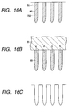
- Figs. 16A to 16C diagrammatically show how the interior of pores in the porous layer stands when cleaned with the aqueous solution containing an alcohol and/or acetic acid, after the anodization is completed.
- Fig. 16A shows a cross section of the porous layer immediately after it has been taken out to the atmosphere after the anodization is completed.
- Reference numeral 701 denotes a substrate; 702, pores; and 80, an electrolytic solution.
- Fig. 16B shows how the porous layer is cleaned with the aqueous solution containing an alcohol and/or acetic acid.
- the above contact angle ⁇ is so small that the solution can enter the pores with ease.
- the aqueous solution containing an alcohol and/or acetic acid, 83, and the electrolytic solution 80 intermingle fast with each other.
- the cleaning with water may sufficiently be carried out, so that the concentration of the electrolytic solution 80 is well lowered and almost all the electrolytic solution in the pores is replaced with water.
- This is then dried with a spin dryer or the like, thus, as shown in Fig. 16C, a porous silicon layer where any secondary products ascribable to HF are present in the pores can be obtained.
- Single-crystal silicon wafers are prepared as the non-porous body 1, the surface of each wafer is made porous in a depth of from about 1 ⁇ m to about 30 ⁇ m by means of the anodizing unit as shown in Fig. 6 or 12, thus a porous single-crystal silicon layer is formed as the porous layer 2.
- the porous layer formed here may preferably be made to have a porosity of from about 5% to 70%, and more preferably from 10% to 50%, in approximation. Also, anodizing current density, HF concentration or the like is changed in the course of the anodization so that the porous layer can be made to have an at least two-layer multi-layer structure having porosities which are higher inside the substrate than at the surface.
- the silicon wafers whose surfaces have been made porous are cleaned with a cleaning solution comprised of an aqueous solution containing an alcohol and/or acetic acid in a concentration of at least 4% by weight. Thereafter, the cleaning solution is replaced with pure water to clean the silicon wafers, followed by drying.
- a cleaning solution comprised of an aqueous solution containing an alcohol and/or acetic acid in a concentration of at least 4% by weight.
- the silicon wafers thus cleaned are each optionally subjected to heat treatment at about 200°C to about 600°C to oxidize the inner walls of pores in the porous layer to form oxide films on the inner-wall surfaces.
- the non-porous layer 3 comprised of single-crystal silicon is formed by CVD, sputtering, molecular-beam epitaxy or liquid-phase epitaxy.
- a silicon oxide film is optionally formed as the insulating film 4.
- the surface of the insulating film 4 and the surface of a single-crystal silicon wafer or supporting base 5 comprised of quartz glass are brought into contact to bond them.
- the resultant multi-layer structure may be subjected to heat treatment in an atmosphere of an inert gas or in an atmosphere of an oxidative gas, or to anodic bonding.
- a dividing member such as a wedge or a blade is inserted to the side face of the multi-layer structure to divide the multi-layer structure into two parts.
- the porous layer having a low mechanical strength, is cracked at its interior or interface and the multi-layer structure is divided into two parts.
- a fluid such as liquid and gas may be jetted to the side face of the multi-layer structure to divide the multi-layer structure mechanically.
- the multi-layer structure may be irradiated by light to generate heat therein or may be heated from the outside so that an internal stress can be produced in the multi-layer structure, and the force thereby produced may be utilized to divide the multi-layer structure.
- the non-porous layer comes to have been transferred onto the supporting base. Since a residual layer of the porous layer 2 is present on this non-porous layer, this layer is selectively etched with the etchant described previously. According to the present embodiment, any unwanted secondary product does not remain in the pores of the porous layer, and hence the non-porous layer after the etching can be free from any uneven film thickness.
- the non-porous layer on the supporting base may optionally be subjected to heat treatment in a reducing atmosphere containing hydrogen, to make the surface smooth and also outwards diffuse and remove boron and so forth contained in the non-porous layer.
- a bonded substrate having the non-porous layer can be obtained which is preferable as an SOI substrate.
- Single-crystal silicon wafers are prepared as non-porous treatment targets. These are each subjected to anodization using the anodizing unit shown in Fig. 6 or 12, to form a porous silicon layer 2 as shown in the step S11 in Fig. 10.
- a low-porosity, first porous layer having a porosity of from 5% to 30% and a thickness of from 1 ⁇ m to 29 ⁇ m may be formed under a low current density.
- a high-porosity, second porous layer having a porosity of from 30% to 70% and a thickness of from 1 nm to 3 ⁇ m may be formed beneath the first porous layer.
- the cleaning is carried out using the system shown in Figs. 7 to 9 and 13 or 14.
- the interior of pores of the porous silicon layer 2 having the double-layer structure with porosities different from each other is cleaned with the cleaning solution containing an alcohol and/or acetic acid.
- the cleaning of the present invention is particularly effective.
- the porous silicon layer 2 is cleaned with pure water, followed by drying.
- the porous silicon layer 2 is subjected to heat treatment at 200°C to 600°C in an oxidizing atmosphere to form oxide films on the pore inner walls.
- Oxide film formed on the layer surface of the porous silicon layer 2 whose pore inner walls have been oxidized is removed with diluted hydrofluoric acid. At this stage, the greater part of the oxide films on the pore inner walls stand remaining.
- the wafers on each surface of which the porous silicon layer 2 has been formed are set in an epitaxial growth apparatus, and the porous silicon layer 2 is prebaked in an atmosphere of hydrogen at a temperature raised to 900°C to 1,000°C.
- a silicon gas such as SiH 4 is introduced to stop up the surface pores of the porous silicon layer 2.
- the introducing of silicon gas is once stopped, and heat treatment is made in an atmosphere of hydrogen at a temperature raised to 1,000°C to 1,200°C.
- a silicon gas such as SiH 2 C1 2 is introduced to carry out epitaxial growth at a temperature dropped to 900°C to 1,000°C, to form a non-porous layer 3 on the porous silicon layer 2 whose pore inner walls have been oxidized.
- An insulating layer is formed on the non-porous layer 3.
- the insulating layer formed is bonded to the supporting base 5 to form a multi-layer structure, followed by heat treatment at 1,000°C to 1,200°C.
- a wedge made of resin or metal is inserted to the side face of the multi-layer structure to cause the porous layer of the multi-layer structure to be cracked at its side face.
- a fluid comprised of liquid or gas is jetted to the side face of the multi-layer structure to cause the porous layer to be further inward cracked.
- the multi-layer structure is divided at the interface between the high-porosity second porous layer and the low-porosity first porous layer.
- the low-porosity first porous layer having oxide films in its pore inner walls and remaining on the non-porous layer 3 transferred to the supporting base 5 side is removed by etching or the like. Since the HF in the pores has well been removed by cleaning after the anodization, the remaining porous layer can uniformly be removed.
- the surface of the non-porous layer 3 is made smooth by hydrogen annealing or the like.
- the non-porous layer 3 thus obtained can have a smooth surface free of any uneven film thickness.
- a silicon wafer as a treatment target was set in the unit shown in Fig. 6, and as an electrolytic solution an anodizing electrolytic solution prepared by mixing hydrofluoric acid of 49% by weight in HF concentration, water and ethanol in a volume ratio of 1:1:1 was fed into the bath.
- a direct-current voltage providing a constant electric current of 7 mA/cm 2 was applied to the wafer for 10 minutes.
- a porous silicon layer having a porosity of about 20% was uniformly formed on the one surface of the wafer in a thickness of 12 ⁇ m.
- the electrolytic solution was discharged through the drain, and a cleaning solution prepared by mixing isopropanol and water in a volume ratio of 1:1 was poured into the bath from the upper part.
- This cleaning solution was retained for 1 minute in the state the bath is filled with it, to carry out cleaning, and thereafter the cleaning solution was discharged outside the bath.
- Example 1 the cleaning step making use of the cleaning solution containing an alcohol as described above was omitted, and the wafer cleaned with pure water was spin-dried immediately after the anodization. The wafer obtained was left in the atmosphere for 10 hours. As a result, the porous silicon surface of the wafer changed in structure to become cloudy.
- anodization was carried out under the same conditions as in Example 1.
- the wafer thus anodized was moved to the cleaning unit 41 by means of the horizontal transfer robot.
- the wafer was rotated at 500 r.p.m. while feeding ethanol (100%) from the nozzle to the wafer to clean the wafer surface for 20 seconds.
- the wafer was moved to the pure-water cleaning unit 42 by means of the horizontal transfer robot, where the wafer was rotated at 400 r.p.m. while jetting out pure water from the upper nozzle and lower nozzle to clean the wafer for 15 minutes. After the cleaning, the jetting of pure water was stopped, and the wafer was rotated at 800 r.p.m. in the same unit to carry out drying.
- the porous silicon surface of the wafer cleaned in this way did not change even after it was left for a week in the same manner as in Example 1, and maintained a very stable state.
- the anodization, the cleaning with alcohol, the cleaning with pure water and the drying were carried out in the same manner as in Example 2 except that in the cleaning with pure water an ultrasonic vibrator was built in at the tip of the upper nozzle so that the pure water provided with ultrasonic vibration was fed to the wafer to more improve the effect of cleaning.
- Example 2 While in Example 2 the cleaning with pure water had to be carried out for 15 minutes, the same cleaning effect as that in Example 2 was obtained by the cleaning for 10 minutes because of the use of the pure water made to have ultrasonic action.
- Example 4 is an example in which the cleaning with pure water and the drying were carried out using the unit shown in Fig. 8.
- the anodization and the cleaning with alcohol were carried out under the same conditions as in Example 2. Thereafter, the substrate was cleaned with pure water using the unit shown in Fig. 8. Subsequently, in the state the substrate was kept hermetically closed in the same bath, it was spin-dried and simultaneously dried by vacuum deaeration. As a result, the water content little remained in the pores, and stabler porous silicon was obtainable.
- a voltage was applied for 7 minutes so as to provide a constant electric current of 10 mA/cm 2 in current density at the time of anodization, to make porous an n-type silicon wafer having a resistivity of 0.007 ⁇ cm.
- a porous silicon layer having a porosity of about 70% was uniformly formed on the one surface of the wafer in a thickness of 12 ⁇ m.
- This wafer was immediately put in the cleaning unit shown in Fig. 9, to carry out alcohol cleaning using propanol vapor, and the wafer thus cleaned was dried while drawing it upwards.
- a 6-inch p-type (0.01-0.02 ⁇ cm) silicon wafer (thickness: 625 ⁇ m) was prepared.
- an aqueous HF solution prepared by mixing hydrofluoric acid of 49% by weight in HF concentration and ethanol in a volume ratio of 2:1 was fed into the anodizing bath.
- Anodization electric current was set at 1 mA/cm 2 , and anodization was continued for 11 minutes to form a porous silicon layer on the surface of the silicon wafer.
- the silicon wafer having been thus anodized was immersed in an aqueous solution containing 10% by weight of isopropanol, and was left for 3 minutes. Thereafter, the silicon wafer was immersed in pure water for 10 minutes to clean it, followed by drying.
- This silicon wafer was subjected to heat treatment at 400°C for 1 hour in an atmosphere of oxygen in an oxidizing furnace to oxidize pore wall surfaces of the porous layer.
- the oxide film formed on the porous layer surface was removed with an aqueous HF solution.
- the wafer was put in a CVD system to carry out baking in an atmosphere of hydrogen, followed by epitaxial growth to form, on the porous layer whose pore wall surfaces have been oxidized, a 0.3 ⁇ m thick epitaxial layer formed of non-porous single-crystal silicon.
- the surface of this epitaxial layer was oxidized at 1,100°C by hydrogen combustion to form a 0.2 ⁇ m thick silicon oxide film.
- the bonded substrate was subjected to hydrogen annealing to obtain an SOI substrate having an active layer in a thickness of 0.2 ⁇ m and a buried oxide film in a thickness of 0.2 ⁇ m, which was formed of non-porous single-crystal silicon and had a smooth surface.
- Example 6 The same silicon wafer as that in Example 6 was prepared, and was subjected to anodization under the same conditions as in Example 6.
- the wafer was immersed for 3 minutes in a bath filled with a cleaning solution comprised of pure water to which 15% by weight of isopropanol was added. Thereafter, the cleaning solution was discharged out of the bath, and then the same bath was filled with pure water to clean the wafer with the pure water for 10 minutes.
- a cleaning solution comprised of pure water to which 15% by weight of isopropanol was added.
- Example 6 Thereafter, the same treatment as that in Example 6 was carried out to etch the porous silicon layer selectively.
- the above process yielded an SOI substrate having an active layer in a thickness of 0.2 ⁇ m and a buried oxide film in a thickness of 0.2 ⁇ m.
- Example 6 The same silicon wafer as that in Example 6 was prepared, and was subjected to anodization under the same conditions as in Example 6. The wafer having been thus anodized was immersed in pure water, and was left for 10 minutes to effect cleaning, followed by drying.
- Example 6 the same treatment as that in Example 6 was carried out to etch the porous silicon layer selectively.
- spotlike uneven film thickness 11 like the one shown in Fig. 21 was observable which was 2 mm to 7 mm in diameter and was a film thickness smaller by about 2 nm to about 7 nm than that of the surrounding area. This uneven film thickness having thus occurred did not easily disappear even when the wafer was thereafter subjected to hydrogen annealing.
Abstract
Description
- This invention relates to a method of cleaning a porous body, and a process for producing a porous body, a non-porous film or a bonded substrate. More particularly, this invention belongs to a technical field of a production process in which a method of cleaning a porous body after anodization can be improved to form a non-porous film having a uniform thickness.
- In the following description, the case of porous silicon is taken as an example of the porous body.
- Porous silicon was discovered by A. Uhlir and D.R. Turner in the course of their researches made on the electrolytic polishing of single-crystal silicon biased to positive potential, in an aqueous hydrogen fluoride (hereinafter often simply "HF") Solution (i.e., hydrofluoric acid).
- Since then, with utilization of the property of porous silicon that is rich in reactivity, studies are made on its application to the step of interelement isolation that requires formation of a thick insulating material in a silicon integrated-circuit fabrication process, and a technique of FIPOS (full isolation by porous oxidized silicon) has been developed in which device elements are full-isolated by a porous silicon oxide film (K. Imai, Solid-state Electron 24, 159, 1981).
- Recently, also proposed in, e.g., Japanese Patent No. 2608351 and U. S. Patent No. 5,371,037, is a technique in which a silicon epitaxial layer grown on a porous silicon substrate is bonded to the surface of an amorphous substrate or single-crystal silicon substrate optionally via an oxide film to obtain an SOI (silicon on insulator) substrate.
- Besides, Japanese Patent Application Laid-Open No. 6-338631 discloses a technique taking note of porous silicon as a light-emitting material such as what is called a photoluminescence material or electroluminescence material.
- Anodization is commonly used to form porous bodies.
- As an example of the formation of porous bodies, an apparatus for producing porous silicon by subjecting a silicon substrate to anodization is shown in Fig. 18.
- The apparatus or unit shown in Fig. 18 is one disclosed in Japanese Patent Application Laid-Open No. 60-94737. This anodization apparatus comprises
anodization baths baths negative electrode 63 and apositive electrode 64, respectively. Thebaths rings baths rings baths aqueous HF solutions - Some anodization apparatus are also proposed besides this.
- Meanwhile, with regard to methods of cleaning porous semiconductor substrates after the anodization has been effected, an example is reported in Japanese Patent Application Laid-Open No. 10-64870, but it appears that very few examples have been reported other than this.
- For the cleaning of porous bodies structurally having a high surface activity, liquid chemicals such as an aqueous solution of sulfuric acid and hydrogen peroxide (hereinafter "SPM"), an aqueous solution of ammonia and hydrogen peroxide (hereinafter "SC-1") and an aqueous solution of hydrochloric acid and hydrogen peroxide (hereinafter "SC-2") can not be used, which are commonly used to remove organic matters, particle deposits or metal deposits. Accordingly, a cleaning method is proposed in which pure water provided with ultrasonic energy is used in place of these to remove foreign matters having adhered to porous layer surfaces, as disclosed in Japanese Patent Application Laid-Open No. 10-64870. Fig. 19 is a flow chart of the steps of such cleaning. A porous body having come out after it has been anodized in a step STP1, is cleaned in a step STP2 with the pure water provided with ultrasonic energy, followed by drying in a step STP3.
- The above publication also discloses a method in which the porous layer surface is hydrophilic-treated with ozone water or hydrogen peroxide water and thereafter cleaned with the pure water provided with ultrasonic energy.
- However, in the cleaning of porous semiconductors, of course the cleaning of surfaces is indispensable, but it is important how the anodizing electrolytic solution having entered fine pores are removed. This is because, however the surface has been cleaned, the electrolytic solution (usually an aqueous HF solution with a concentration of 10% by weight to 50% by weight) remaining in pores causes a change in structure of the porous body.
- In addition, the HF having vaporized gradually as HF gas from the interior of pores may corrode the surrounding devices. Moreover, particles generated as a result of corrosion may contaminate the substrate.
- Furthermore, since it takes a time to replace the HF in pores with the pure water, the cleaning with pure water must be carried out for a long time. In such a case, the porous body may crush in the pure water to cause a difficulty that particles are generated in a large quantity.
- Such porous bodies are also preferably used in the production of bonded substrates utilized in SOI techniques.
- Fig. 20 is a diagrammatic view to illustrate a process of producing a bonded substrate.
- First, in a step S1, a
non-porous substrate 1 such as a single-crystal silicon wafer is prepared and its surface is made porous by anodization to form aporous layer 2 formed of single-crystal silicon. - Next, in a step S2, the
porous layer 2 is cleaned with pure water to wash away the foreign matters adhering to the porous layer or the electrolytic solution for anodization. - Subsequently, in a step S3, a
non-porous layer 3 formed of single-crystal silicon is epitaxially grown on theporous layer 2 by, e.g., CVD (chemical vapor deposition). - Then, in a step S4, the surface of the non-porous layer is thermally oxidized to form an insulating layer 4.
- In a subsequent step S5, the surface of the insulating layer 4 is bonded to a supporting
base 5 prepared separately, to from a multi-layer structure in which the non-porous layer 4 is positioned inside. - In a step S6, the non-porous portion of the
substrate 1, having remained without being made porous, is removed by grinding and by ion etching subsequent thereto. - Then, in a step S7, the
porous layer 2 thus uncovered is removed by etching with an aqueous solution containing HF and H2O2. - The surface of the non-porous semiconductor layer may optionally be smoothed by heat treatment made in a reducing atmosphere containing hydrogen, thus a bonded substrate is obtained which has a thin semiconductor layer on an insulating layer formed on a supporting base. Fig. 21 illustrates the top surface of a bonded substrate obtained in this way.
Reference numeral 12 denotes a notch. - However, upon observation of the surface of the non-porous semiconductor layer thus formed, few circular spots 11 (hazes) which look optically different from their surrounding area are often seen. As a result of careful observation of the
circular spots 11, this has been found due to the fact that the non-porous layer present on the insulating layer formed on the supporting base stands locally small in thickness (or thin). Namely, the non-porous layer proved to have locally caused microscopically uneven film thickness. - An object of the present invention is to provide a porous-body cleaning method by which the anodizing solution can well be removed from the porous body without causing any change in porous structure of the porous body and even when cleaned for a short time, and provide a process for producing a porous body.
- Another object of the present invention is to provide a porous-body cleaning method which may hardly cause corrosion of the surrounding devices, and a process for producing a porous body.
- The cleaning method of the present invention is a cleaning method of cleaning a porous body formed by anodization, and is characterized by comprising the step of cleaning the porous body after the anodization is completed, with a cleaning solution containing at least one of an alcohol and acetic acid.
- The porous-body production process of the present invention is characterized by comprising the step of subjecting a non-porous body to anodization and thereafter cleaning a porous body with a cleaning solution containing at least one of an alcohol and acetic acid.
- Still another object of the present invention is to provide a process for producing a non-porous film and a bonded substrate which are free of uneven film thickness.
- The above process of the present invention is characterized by a process for producing a non-porous film or a bonded substrate, the process comprising the steps of forming a porous layer by anodization, bonding to a supporting base a non-porous layer formed on the porous layer, and removing the porous layer, wherein;
- the process further comprises the step of, after the anodization is completed, cleaning the porous layer with a cleaning solution containing at least one of an alcohol and acetic acid.
-
- At first, the present inventors had thought that the hazes stated previously occur because of conditions at the time of anodization or etching conditions which are not optimized when the porous layer is removed from the surface of the non-porous layer. However, any adjustment of these conditions was found not to so much affect the controlling of uneven film thickness. Then, further studies made by the present inventors have revealed that the uneven film thickness is caused depending on the treatment made after anodization.
- Accordingly, in the present invention, the above cleaning method is employed in wet cleaning after anodization so that the non-porous layer of the bonded substrate may hardly cause uneven film thickness.
-
- Fig. 1 is a flow chart of the steps of cleaning a porous body according to the present invention.
- Fig. 2 is a diagrammatic cross-sectional view of a porous body standing immediately after anodization.
- Fig. 3 is a diagrammatic cross-sectional view of a porous body after the porous body standing as shown in Fig. 2 has been cleaned with pure water immediately after anodization.
- Fig. 4 is a diagrammatic view to illustrate the action of the cleaning with an alcohol according to the present invention.
- Fig. 5 is a diagrammatic view to illustrate the action of the cleaning with pure water, used in the present invention.
- Fig. 6 is a diagrammatic view showing an anodization-and-cleaning unit used in the present invention.
- Fig. 7 is a diagrammatic view showing a system having an anodization unit and a cleaning unit separately, used in the present invention as another type.
- Fig. 8 is a diagrammatic view showing a cleaning-and-drying unit used in the present invention as another type.
- Fig. 9 is a diagrammatic view showing a cleaning-and-drying unit used in the present invention as still another type.
- Fig. 10 is a flow chart of a process for producing a bonded substrate according to the present invention.
- Fig. 11 is a diagrammatic view showing part of an anodization unit used in the present invention.
- Fig. 12 is a diagrammatic view showing an anodization unit used in the present invention.
- Fig. 13 is a diagrammatic view showing a system having an anodization unit and a cleaning unit separately, used in the present invention.
- Fig. 14 is a diagrammatic view showing a system having an anodization unit and a cleaning unit separately, used in the present invention as another type.
- Fig. 15A, Fig. 15B, Fig. 15C and Fig. 15D are diagrammatic views to illustrate the action of cleaning by a conventional method.
- Fig. 16A, Fig. 16B and Fig. 16C are diagrammatic views to illustrate the action of cleaning according to the present invention.
- Fig. 17 is a top plan view showing an appearance of a bonded substrate obtained by the process of the present invention.
- Fig. 18 is a diagrammatic view showing a conventional anodization unit.
- Fig. 19 is a flow chart of the steps of cleaning a porous body in a conventional method.
- Fig. 20 is a flow chart of a conventional process for producing a bonded substrate.
- Fig. 21 is a top plan view showing an appearance of a bonded substrate obtained by a conventional process.
-
- Fig. 1 is a flow chart of the cleaning method of the present invention.
- First, in a step S1, a non-porous body is treated by anodization to form a porous body. ("Porous body" is herein meant to embrace a material which is porous on the whole and a material having a porous layer described later.)
- Subsequently, in a step S2, the porous body is cleaned by immersing it in a 100% alcohol or an aqueous alcohol solution, by adding a 100% alcohol or an aqueous alcohol solution dropwise to the porous body, or by exposing the porous body to the vapor of a 100% alcohol or an aqueous alcohol solution.
- Next, optionally in a step S3, the porous body is cleaned with pure water. In this step, too, the porous body may be immersed in the pure water, the pure water may be added dropwise to the porous body, or the porous body may be exposed to water vapor (steam). Here, it is also preferable to clean it with pure water provided with ultrasonic energy by the use of an ultrasonic vibrator.
- Then, in a step S4, the porous body is dried to complete a series of cleaning steps.
- Usually, in the case where semiconductors such as silicon are subjected to anodization to form porous bodies, the anodization is effected by applying an electric field to the silicon substrate in an aqueous HF solution having relatively a high concentration. The silicon surface opposing the negative electrode (this silicon surface serves substantially as the anode) is so etched that fine pores extending along the direction of the electric field are formed, so that it comes to have a porous structure.
- The pores thus formed have a size distributing from tens of nanometers to hundreds of nanometers, and have a density reaching 1011 pores/cm2 or higher. The size and density of the pores change depending on the conditions of anodization, i.e., HF concentration, values of anodization voltage or anodization electric current, and conductivity type or specific resistance of the substrate. Their porosity may be controlled by adjusting these conditions, whereby structures most suited to light-emitting materials or porous bodies most suited to base structures for epitaxial growth can be produced relatively with ease.
- However, even porous bodies obtained exactly as designed, they may cause a structural change of porous layers or may be involved in secondary contamination, unless they are sufficiently cleaned after anodization. Figs. 2 to 5 are diagrammatic views to illustrate how the interior of pores of the porous body stands.
- Such structural change and secondary contamination are caused by, as shown in Fig. 2,
aqueous HF solution 80 remaining in the pores as stated previously and evaporating gradually in the form of gas. Accordingly, a cleaning method is necessary that does not allow any anodizing solutionaqueous HF solution 80 to remain in the pores.Reference numeral 81 denotes pore walls of the porous body. - If the substrate is only cleaned with pure water after the anodization is completed, although the HF component on the layer surface of the porous layer may be removable, it is difficult to remove the HF remaining in the pores. This is because, as shown in Fig. 3, the layer surface of the porous layer turns hydrophobic as a result of its contact with the
aqueous HF solution 82 and, even though it is washed with water thereafter, it has become difficult for the water to penetrate into the pores. Stated specifically, in measurement of changes with time of specific resistance of the pure water in which the porous body having been subjected to anodization stand immersed, there occurs a phenomenon that the value of specific resistance does not return to the original value. This is just because the HF having gradually vaporized in the pores dissolves in the pure water at a low rate. - In order to clean the interior of pores, it is also experimentally necessary at least to replace the anodizing solution in the bath with the pure water within 3 minutes after the anodization is completed, and to carry out rinsing with pure water sufficiently. Such procedure, however, narrows the freedom of the cleaning process and also makes the designing of cleaning unit restrictive.
- The present inventors repeated various experiments. As a result, they have discovered that the cleaning with pure water to which a 100% alcohol or an aqueous alcohol solution has been added readily enables replacement of the anodizing solution in pores with the cleaning solution, and thus has accomplished the present invention.
- Once the porous body is immersed in the cleaning solution containing an alcohol, as shown in Fig. 4 the
cleaning solution 83 penetrates into fine pores to become intermingled with the anodizing solution having remained in the pores. Then, even when the porous body is exposed to the atmosphere as it is, its surface is kept standing wet for a while. More specifically, the surface of the porous body, too, is covered with alayer 84 formed of the cleaning solution or anodizing solution. This porous body is anew immersed inpure water 85 as shown in Fig. 5, so that thewater 85 penetrates into the pores with ease, thus theanodizing solution 80 remaining therein can be replaced with thepure water 85. - After that, even if the
pure water 85 has remained in the pores of the porous body, the water evaporates naturally. In that course, what evaporates is only the water, and hence it little causes the corrosion of surrounding devices or the change of properties or deterioration of the porous body's structure itself. - The porous body used in the present invention may include semiconductors such as Si, Ge, GaAs, GaAlAs, SiC, SiGe and C. In particular, porous silicon having a porosity lower than 70% is preferred as a base material for epitaxial growth, and silicon having a porosity of 70% or higher as a light-emitting material.
- The anodization used in the present invention is carried out in an aqueous HF solution, or an aqueous solution of HF and an alcohol.
- As the alcohol used in the cleaning step of the present invention, usable are methanol, ethanol and propanol. The cleaning solution may be any those containing at least 4% by weight, and preferably at least 10% by weight, of the alcohol.
- After the cleaning with the cleaning solution containing an alcohol, the porous body may preferably be cleaned (or rinsed) with pure water. Here, as mentioned previously it may be cleaned with pure water provided with ultrasonic energy, which may be within the range of from 600 KHz to 2 MHz. This can more improve the efficiency of replacement of HF with water.
- In the case of the present invention, after the anodization is completed, the porous body may preferably be moved from the anodizing solution to the cleaning solution in a time as short as possible, which, however, is by no means limited to 3 minutes, and may be elongated up to about 10 minutes.
- A cleaning unit (an anodization-and-cleaning unit) used in the present invention will be described below with reference to Fig. 6.
- The cleaning unit shown in Fig. 6 is so constructed as to also serve as an anodization unit. This unit is so constructed as to consist chiefly of a
bath 61 that functions also as a substrate holder and can hold the anodizing solution and the cleaning solution, a flat-platenegative electrode 63 provided with many holes, and apositive electrode 64 up and down movable relatively to thebath 61. Thebath 61 is made of a fluorocarbon type fluorine-resistant material such as tetrafluoroethylene resin, and has anopening 69 at the bottom of thebath 61. Then, along the inside edge of thisopening 69, a sealingmember 65 such as a substrate suction ring is set to the bottom of thebath 61. The substrate attraction (suction)ring 65 is flat at its attraction portion, and in its plane a vacuum groove (not shown) is formed which communicates with a communicatingpath 22 for vacuumizing/pressurizing its space to vacuum-attract or pressurizing-release a treatment target W. The treatment target W, such as a silicone wafer, is attracted and held to thesubstrate suction ring 65 at its under-side perimeter. In this state, an electrolytic solution is poured as ananodizing solution 67 into thebath 61 from afeed nozzle 27 until thenegative electrode 63 stands immersed in the electrolytic solution. Thenegative electrode 63 is made of a platinum plate having substantially the same diameter as the treatment target, and a plurality of holes like those made by punching are made in the plate so that reaction by-product gases such as hydrogen generated during the anodization can be removed. Thepositive electrode 64 passes through theopening 69 of thebath 61 to come into direct contact with the back of the treatment target W. Thispositive electrode 64 by no means comes into direct contact with the electrolytic solution, and hence is formed of aluminum. Thepositive electrode 64 is placed on astand 25 together with an up-and-down means 24, and is provided with a communicatingpath 23 for vacuumizing/pressurizing its space to vacuum-attract or pressurizing-release the treatment target W. - To carry out anodization, the
positive electrode 64 is kept raised to the uppermost position by means of the up-and-down means 24, and the treatment target W is placed thereon. The communicatingpath 23 is vaccumized to attract the treatment target W to thepositive electrode 64 by suction. Thepositive electrode 64 is descended to bring the treatment target W into contact with the bottom of thebath 61. Then the communicatingpath 22 is vacuumized to attract the treatment target W, at its perimeter, to the sealing member 6 by suction. After anodization is ready, the aqueous HF solution is fed into thebath 61 through thefeed nozzle 27. After it has reached a predetermined quantity, a direct-current voltage is applied across thenegative electrode 63 and thepositive electrode 64. At this time, the anodization may be continued while feeding the aqueous HF solution continuously and allowing it to overflow. In Fig. 6,reference numeral 26 denotes an overflow bath. - After the anodization is completed, the
positive electrode 64 is descended and also thenegative electrode 63 is brought aside out of thebath 61. Adrain 21 is opened, and the anodizing solution, 67, is discharged therethrough to once make thebath 61 empty. Thereafter, the cleaning solution containing an alcohol is fed through the feed nozzle. At this time, too, the cleaning may be carried out while allowing the cleaning solution to overflow. The cleaning solution feed nozzle may be provided independently from the HF solution feed nozzle. - Subsequently, the
drain 21 is again opened to discharge the cleaning solution containing an alcohol, and thereafter the pure water is fed into thebath 61 through thefeed nozzle 27. It is preferable to optionally attach an ultrasonic vibrator to thefeed nozzle 27 orbath 61 so that the pure water cleaning solution can be provided with ultrasonic energy. - After the cleaning with pure water, the
drain 21 is opened to discharge the pure water. The vacuum attraction through the communicatingpath 22 is stopped, and thepositive electrode 64 is ascended, where the vacuum attraction through the communicatingpath 23 is stopped to take out the treatment target W. - Fig. 6 illustrates a state where the
positive electrode 64 is at the descended position, so as to make it easy to understand the construction of the unit. During the anodization, it is at the position coming into contact with the back of the treatment target W. - Fig. 7 shows a porous-body cleaning system as another example used in the present invention.
- The system shown in Fig. 7 has an
anodization unit 40 having substantially the same construction as the one shown in Fig. 6, analcohol cleaning unit 41 and a pure-water cleaning unit 42. - After the anodization is carried out in the
anodization unit 40, the treatment target W having been anodized is, after the anodizing solution in thebath 61 is completely discharged, moved to thealcohol cleaning unit 41 by means of a horizontal transfer robot (not shown). In analcohol cleaning bath 33, arotary chuck holder 34 vacuum-attracts the treatment target W on its back to hold it. In that state, the cleaning solution containing an alcohol is fed through anozzle 35 provided above the treatment target W. In this unit, the cleaning solution containing an alcohol is jetted out toward the treatment target W while rotating it at a predetermined number of revolutions. Thus, the cleaning with an alcohol is effected. - Next, the treatment target W on which the cleaning with an alcohol has been completed is moved to the pure-
water cleaning unit 42 by means of a horizontal transfer robot. The treatment target W is so arranged as to be held at its peripheral edge with asubstrate chuck 37, tightly by an external force. Then, the pure water is fed through anupper nozzle 38 and alower nozzle 39. In this unit, too, the pure water is jetted out of both theupper nozzle 38 and thelower nozzle 39 while rotating the treatment target W at a predetermined number of revolutions. Stopping the jetting of pure water, the treatment target W may further be spin-dried while continuing its rotation. - Fig. 8 shows a pure-water cleaning unit used in the present invention. This unit is a modification of the pure-
water cleaning unit 42 shown in Fig. 7, and is a unit having abath 36 provided with a hermeticallyclosable cover 51 so that, after rinsing with pure water, the hermetically closed space defined by thebath 36 and thecover 51 can be evacuated through anexhaust path 52 to carry out spin-drying while keeping vacuum the inside of the hermetically closed space. Where water content remains in the pores, it may adversely affect the subsequent processing steps. For example, when epitaxial growth is effected on the porous silicon, a trace quantity of water may evaporate from the interior of pores of the porous body and diffuse into an epitaxial growth chamber to bring about defects in an epitaxially grown film. In order to prevent this, it is fairly effective to carry out such vacuum deaeration finally. - Fig. 9 shows an alcohol cleaning unit used in the present invention. A cleaning
bath 53 is provided therein with anozzle 54 through which the vapor of the cleaning solution containing an alcohol is fed. A treatment target W is inserted from above thebath 53 into it, and the vapor of the cleaning solution containing an alcohol is fed through thenozzle 54 to fill the inside of the bath with vapor to carry out cleaning. Thereafter, the treatment target W may slowly be taken out of the bath to the external dry atmosphere, so that the alcohol remaining in the treatment target W vaporizes, thus the treatment target W can be dried. If the pure water is directly jetted onto the porous body having a very high porosity, e.g., a porosity of 70% or higher, or ultrasonic water is imparted thereto to carry out physical cleaning, the porous body tends to crush. Accordingly, such a unit may be used, whereby even a porous body having a high porosity can be cleaned without break of the porous body. Porous silicon having a porosity of 70% or higher is preferably applied as a light-emitting material. Compared with the conventional case where treatment targets are cleaned with only pure water after anodization, those subjected to cleaning with alcohol vapor and drying after anodization may cause no change in the porous structure. Hence, the material can maintain light-emission intensity stably for a long time. - In the foregoing, described is a case where a solution containing an alcohol is used as the cleaning solution. In the present invention, however, acetic acid may also be used in place of the alcohol.
- A process for producing a non-porous film and a process for producing a bonded substrate according to the present invention will be described below.
- Fig. 10 is a flow chart of a process for producing a bonded substrate according to the present invention.
- First, in a step S11, a
non-porous body 1 is treated by anodization to form a porous layer at least on its surface. - In a step S12, the
porous layer 2 is cleaned by immersing it in a 100% alcohol or an aqueous alcohol solution, by adding a 100% alcohol or an aqueous alcohol solution dropwise to theporous layer 2, or by exposing theporous layer 2 to the vapor of a 100% alcohol or an aqueous alcohol solution. In this step S12, acetic acid may also be used in place of the alcohol. An example of the cleaning method is as described above. - Next, optionally in a step S13, the
porous layer 2 is cleaned with pure water. In this step, too, theporous layer 2 may be immersed in the pure water, the pure water may be added dropwise to theporous layer 2, or theporous layer 2 may be exposed to water vapor (steam). Here, it is also preferable to clean it with pure water provided with ultrasonic energy by the use of an ultrasonic vibrator. Then, theporous layer 2 is dried to complete a series of cleaning steps. Examples of the washing with pure water and drying are also as described above. - Next, the
porous layer 2 is oxidized at a low temperature to form a thin oxide layer on inner wall surfaces of pores. - Subsequently, in a step S14, a
non-porous layer 3 is formed on theporous layer 2. The step S14 may be effected prior to the step S11 to form thenon-porous layer 3 on thenon-porous body 1 and thereafter make the whole single-crystal silicon porous from the back. Alternatively, anodization may be so carried out that the back side of thenon-porous body 1 is made porous to leave thenon-porous layer 3 on the surface side. - Next, in a step S15, an insulating layer 4 is optionally formed on the surface of the
non-porous layer 3 and, as shown in a step S16, thenon-porous layer 3 is bonded to a supportingbase 5 prepared separately, via the insulating layer 4 between them. - In a step S17, pretreatment is made in order to remove the
porous layer 2 from the multi-layer structure thus formed. In the case where thenon-porous body 1 remains as shown in Fig. 10, this is removed from the multi-layer structure by grinding, lapping, polishing or etching. Thereafter, theporous layer 2 uncovered is selectively removed as shown in a step S18, by wet etching with an etchant containing HF, H2O2 and water. - Alternatively, the
non-porous body 1 may be separated (step S17) by applying an external force to the multi-layer structure, or by producing an internal stress therein, so as to cause a break in theporous layer 2 or at its interface with the upper or lower layer. Someporous layer 2 remaining on thenon-porous layer 3 may selectively be removed (step 18) by etching in the same manner as the above. - The bonded substrate thus obtained may further optionally be subjected to heat treatment in a reducing atmosphere containing hydrogen, to make its surface more smooth.
- Since the porous layer can almost be free from any change in porous structure due to the HF or aqueous HF solution having remained therein, the bonded substrate thus obtained does not cause any microscopically uneven film thickness, thus a bonded substrate having a high quality level can be obtained.
- The
porous layer 2 used in the present invention may include layers of, as stated previously, semiconductors such as Si, Ge, GaAs, GaAlAs, SiC, SiGe and C. In particular, porous silicon having a porosity lower than 70% is preferred as a base material used for epitaxial growth. More preferably, the porous layer at its part adjoining or adjacent to the non-porous layer may have a porosity not higher than 30%. The porous layer may preferably have a thickness of from about 1 µm to about 30 µm. - The anodization used in the present invention is carried out in an aqueous HF solution, or an aqueous solution of HF and an alcohol.
- As the alcohol used in the cleaning step of the present invention, usable are methanol, ethanol and propanol. The cleaning solution may be any those containing at least 4% by weight of the alcohol.
- After the cleaning with the cleaning solution containing an alcohol, the porous body may preferably be cleaned with pure water. Here, as stated previously it may be cleaned with pure water provided with ultrasonic energy ranging from 600 KHz to 2 MHz. This can more improve the efficiency of replacement of HF with water.
- In the case of the present invention, after the anodization is completed, the porous body may preferably be moved from the anodizing solution to the cleaning solution in a time as short as possible, which, however, is by no means limited to 3 minutes, and may be elongated up to about 10 minutes.
- The non-porous layer used in the present invention may preferably include, e.g., layers of elemental semiconductors such as Si and Ge, compound semiconductors such as GaAs, GaAlAs, SiC and SiGe, metals, and superconductors. Stated specifically, single-crystal silicon layers, polycrystalline silicon layers and amorphous silicon layers are preferred. In the non-porous layer, device or semiconductor junction such as MOSFET, p-n junction, p-i-n junction and MIS junction may also be formed.
- As the insulating layer provided optionally, preferably usable are layers of insulators or dielectrics, such as silicon oxide, silicon nitride and silicon oxide nitride. This layer may be formed as a single layer or a plurality of layers formed of like materials or different materials.
- The supporting base used in the present invention may include semiconductors such as silicon, metals such as aluminum or stainless steel, ceramics such as alumina, and insulating materials such as quartz glass and plastic films. These supporting bases may also be those on the surface of which a layer of a material different from the material constituting the supporting base itself has been formed. In the case where bonded SOI substrates are produced, the insulating layer may preferably be formed on the surface of the non-porous layer and thereafter bonded to a silicon wafer or a quartz wafer. Also, the supporting base may be a jig used only for the separation.
- In order to remove the porous layer selectively, an etchant is used which may achieve an etching rate to porous bodies that is at least 10,000 times, and preferably at least 100,000 times, the etching rate to non-porous bodies. In the case of porous silicon and non-porous silicon, preferably usable are solutions containing HF and an oxidant, as exemplified by a mixture solution of hydrofluoric acid, nitric acid and acetic acid, a mixture solution of hydrofluoric acid, hydrogen peroxide water and water, a mixture solution of hydrofluoric acid, an alcohol and water, and a mixture solution of hydrofluoric acid, hydrogen peroxide water and alcohol.
- In the present invention, the units shown in Figs. 6 to 9 may be used as the anodization and cleaning unit. Besides these, anodization and cleaning units shown in Figs. 11 to 14 may also be used.
- Fig. 11 shows a holder and a substrate transport robot which are used in an anodization unit in the present invention. Fig. 12 shows the anodization unit. Figs. 13 and 14 show anodization and cleaning systems used in the present invention.
- The unit shown in Fig. 12 is a unit by which three substrates as treatment targets can be anodized in one time. As shown in Fig. 11, a substrate-holding member (hereinafter "holder") 102 in the anodization unit is a square plate provide with a
circular opening 103 at substantially the center thereof. Along theopening 103, a ring-type substrate attraction (suction) pad (hereinafter "pad") 104 is embedded. A groove is made in the pad on its surface, and the interior of the groove can be brought into a vacuum through anevacuation line 105 from the back of the pad.Reference numerals robot 106a holds a treatment target W on its back by vacuum attraction and brings it to come near to theholder 102 so as to be in parallel to its face. Next, therobot 106b is passed from theopening 103 of theholder 102 through the part turning in L-shape, and waits for the treatment target W to come near. Therobot 106b has the function of vacuum attraction like therobot 106a. At the time the back of the treatment target W has come into contact with the leading end of therobot 106b, therobot 106b holds the treatment target W by attraction (suction), and therobot 106a release its attraction to go away upward. Subsequently, therobot 106b moves toward the right as viewed in the drawing, so that the back of the treatment target W comes into contact with thepad 104. Here, the interior of the groove in thepad 104 is kept vacuum by theevacuation line 105, and thepad 104 holds the treatment target W by attraction. Therobot 106b passes through theopening 103 and go away upward. Thus, the treatment target W is held byholder 102. Also, when the treatment target W is detached therefrom, the above procedure is followed in reverse. - As shown in Fig. 12, an
anodizing bath 210 of the anodization unit is fitted with anegative electrode 206a and apositive electrode 206b at its both ends. Threeholders 102 are arranged in series in such a way that they are held between these electrodes fitted in pair. Fig. 12 shows a state where the treatment target W has already been held by eachholder 102. The spaces between theelectrodes holders 102 and between theholders 102 are each filled with anelectrolytic solution 209, and are respectively separated with the treatment targets. Anodization is carried out in this state by applying a direct-current voltage across theelectrodes liquid outlets 208 are opened, and theelectrolytic solution 209 is discharge therethrough. Theseholders 102 functions like the bottom of thebath 61 of the unit shown in Fig. 6. - As shown in Fig. 13, an anodization system installed with the above anodization unit has a
loader 301, ananodizing bath 302, acleaning bath 303, aspin dryer 304 and anunloader 305 in this order from the left as viewed in the drawing. In the direction of this arrangement, a substrate (wafer) sheet-by-sheet transport robot 306 and acarrier transport robot 307 are provided. The substrate sheet-by-sheet transport robot 306 is further constituted of twoportions bath 303 is provided with the function to circulate an aqueous solution containing at least one selected from an alcohol and acetic acid and the function to feed pure water. This system also has asystem 308 in which the electrolytic solution in the anodizing bath is circulatingly filtered. - Substrates as treatment targets W placed in the
loader 301 are set in theholders 102 by thewafer transport robot 306, and are disposed in theanodizing bath 302. - Substrates having been subjected to anodization in the
anodizing bath 302 are taken out of theholders 102 by therobot 306, and are transported to thecleaning bath 303. In thecleaning bath 303, the substrates are cleaned with an aqueous solution containing at least one selected from an alcohol and acetic acid. Subsequently, they are cleaned with pure water in the same bath. - The substrates thus cleaned by the aid of the
robot 307 are transported to arobot dryer 309 together with the carrier, and are once dried there. - Subsequently, the substrates are sheet by sheet taken out from the carrier, and then spin-dried in the
spin dryer 304. - The substrates having been dried are sent out to the
unloader 305. - Thus, the treatment of from the step S11 to the step S13 is carried out in one lot.
- Fig. 14 shows a modification of the system shown in Fig. 13, in which another cleaning bath is added to the cleaning bath provided solely in the system shown in Fig. 13. A
first cleaning bath 310 is a bath having the function to circulate the aqueous solution containing an alcohol and/or acetic acid, and has a filtration system. In asecond cleaning bath 303, only pure water is supplied and the final cleaning with water is carried out. - In the systems of the present invention as shown in Figs. 13 and 14, the units constructed like those shown in Figs. 6 to 9, 11 and 12 may be used as the anodizing bath or the cleaning bath. In Fig. 14, other reference numerals denotes the same as those shown in Fig. 13.
- Again with reference to Fig. 1 and others, the process for producing the non-porous film and bonded substrate according to a preferred embodiment of the present invention will be described in greater detail by taking the case of silicon as an example.
- Single-crystal silicon wafers are prepared as the non-porous body 1 (Fig. 10), the surface of each wafer is made porous in a depth of from about 1 µm to about 30 µm by means of the anodizing unit as shown in Fig. 6 or 12, thus a porous single-crystal silicon layer is formed as the
porous layer 2. The porous layer formed here may preferably be made to have a porosity of from about 5% to 70%, and more preferably from 10% to 50%, in approximation. Also, it is preferable to change anodizing current density, HF concentration and so forth in the course of the anodization so that the porous layer can be made to have an at least two-layer multi-layer structure having porosities different from one another. - Subsequently, using the system shown in Figs. 7 to 9 and 13 or 14, the silicon wafers whose surfaces have been made porous are cleaned with a cleaning solution comprised of an aqueous solution containing an alcohol and/or acetic acid in a concentration of at least 4% by weight. Thereafter, the cleaning solution is replaced with pure water to clean the silicon wafers, followed by drying.
- The silicon wafers thus cleaned are each optionally subjected to heat treatment at about 200°C to about 600°C to oxidize the inner walls of pores in the porous layer to form oxide films on the inner-wall surfaces. The pore walls remain consisting chiefly of silicon.
- On the
porous layer 2, thenon-porous layer 3 comprised of single-crystal silicon is formed by CVD, sputtering, molecular-beam epitaxy or liquid-phase epitaxy. - On the surface of the
non-porous layer 3, a silicon oxide film is optionally formed as the insulating film 4. - The surface of the insulating film 4 and the surface of a single-crystal silicon wafer or supporting
base 5 comprised of quartz glass are brought into contact to bond them. In the case where the insulating film 4 is not formed, thenon-porous layer 3 is bonded to the supportingbase 5. In order to enhance their bond strength, the multi-layer structure thus formed by bonding may be subjected to heat treatment in an atmosphere of an inert gas or in an atmosphere of an oxidative gas, or to anodic bonding. - From the multi-layer structure, the
silicon wafer 1 having remained without being made porous is removed by grinding, lapping or RIE (reactive ion etching) on the back side, which is opposite to the bonded-face side. - The
porous layer 2 thus uncovered is further selectively etched with the etchant as described previously. Thus, a bonded substrate having a non-porous film on the supportingbase 5 is obtained. - The treatment to make the silicon substrate porous by anodization, i.e., to form pores therein is carried out in, e.g., the aqueous HF solution. For this treatment, the presence of holes in silicon crystal is known to be indispensable, and the mechanism of their reaction is presumed as follows.
- First, holes in the silicon substrate having undergone electrolysis in the aqueous HF solution are induced to the surface of the negative-electrode side. As a result, the density of Si-H bonds increases which are present in such a form that they compensate unbonded arms at the surface. At this time, fluorine ions in the aqueous HF solution attack the Si-H bonds nucleophilically to form Si-F bonds. As a result of this reaction, one electron is released to the positive-electrode side simultaneously with the generation of H2 molecules. Because of the polarization characteristics of the Si-F bonds, Si-Si bonds in the vicinity of the surface become weak. Such weak Si-Si bonds are attacked by HF or H2O, and the Si atoms on the crystal surface turn into SiF4 to become liberated from the crystal surface. As a result, hollows (concavities) are produced on the crystal surface, and distribution of electric fields that attracts holes preferentially occurs at this part, so that such surface heterogeniety expands and the etching of silicon atoms progresses continuously along the electric fields. Incidentally, the solution used in the anodization is not limited to the aqueous HF solution, and may be other electrolytic solutions.
- The etching of silicon in the step of anodization is explained by the following reaction scheme.
- Namely, the reaction with hydrofluoric acid brings about the formation of a silicone compound H2SiF6, so that the silicon is etched. The above reaction scheme also shows that the H2SiF6 is formed in a larger quantity with an increase in the concentration of HF. This H2SIF6 has properties that it is very hardly reactive with, i.e., sparingly soluble in, acid (including hydrofluoric acid) or alkali solutions.
- The progress of anodization reaction also brings about the formation of pores of tens to hundreds of angstroms at the substrate surface, and the pores extend ahead along the direction of electric fields. Namely, the electrolytic solution (aqueous hydrofluoric acid solution) enters the pores and causes the reaction at the tip of the pores. Then, even when the electric fields disappear, the pores in which the hydrofluoric acid solution is kept confined generate at random. What comes into question at this stage is that the hydrofluoric acid solution confined in the pores continues the reaction even after the electric fields have disappeared, to continue forming the H2SiF6. Where the H2SiF6 thus formed adheres to the inner walls of the pores, the selective etching of the porous silicon layer, carried out finally in the process, becomes uneven.
- In the selective etching of porous layers, the non-porous layer to be left without being etched, and the porous layer to be removed are both the alike single-crystal silicon in many cases. Hence, although chemical etching rate should be equal in principle, the etchant having soaked on into the pores of the porous layer etches the pore wall surfaces, so that the porous layer comes to be etched not only from the layer surface but also from the interior. Thus, the etching of the porous body stands in a mode where the whole layer breaks down physically.
- Accordingly, in order to etch the porous layer uniformly, the H2SiF6 must be kept from its random generation in the pores. For this end, it is important to replace the HF which remains easily in the pores, with a liquid having no etching action as far as possible. Also, in order to remove the porous layer uniformly, it is preferable to form oxide films on the pore inner walls of the porous layer, where it is also desirable to keep the H2SiF6 from being formed.
- Figs. 15A to 15D diagrammatically show how the interior of pores in the porous layer stands when cleaned with pure water and dried after the anodization is completed.
- Fig. 15A shows a cross section of the porous layer immediately after it has been taken out to the atmosphere after the anodization is completed.
Pores 602 are formed as a result of the anodization of asubstrate 601, and anelectrolytic solution 80 remains in the pores. The electrolytic solution is, as stated previously, a mixture solution of HF and an alcohol in many cases. - Fig. 15B shows how the interior of pores stands after the porous layer has been left for few minutes in the atmosphere. The water content or alcohol content in the
electrolytic solution 80 has evaporated in part and the aqueous HF solution stands remaining in the depths of the pores in the state it has been concentrated. - Fig. 15C shows how the porous layer is cleaned with
pure water 82. - In general, liquid enters the pores by capillarity, and is mixed with thick aqueous HF solution. Subsequently the hydrofluoric acid diffuses on toward the outside of the pores to become replaced gradually with the pure water in the pores. Thus, the cleaning is effected.
- At this stage, the entering depth H in the case where the liquid enters the pores by capillarity is expressed by the following equation.
pure water 82 for cleaning can little enter thepores 602. For this reason, alayer 604 of air is necessarily formed in the vicinity of the surfaces of thepores 602. Once this has occurred, even when the water is tried being removed by drying with a spin dryer or the like after the cleaning with pure water, the hydrofluoric acid in thepores 602 is not replaced with the water to become higher and higher in concentration. Finally the solution remaining in thepores 602 dries up completely, so that, as shown in Fig. 15D, a secondary-product dry matter 606 adheres to the pore wall surfaces. This dry matter 606 is the H2SiF6 stated above. In Fig. 15D, a state is illustrated where the dry matter 606 stands adhered to all the pores. Actually, it adheres to only part of the massive pores, or dry matters 606 having different thickness for each pore may occur, to become uneven. - On the other hand, Figs. 16A to 16C diagrammatically show how the interior of pores in the porous layer stands when cleaned with the aqueous solution containing an alcohol and/or acetic acid, after the anodization is completed.
- Fig. 16A shows a cross section of the porous layer immediately after it has been taken out to the atmosphere after the anodization is completed.
Reference numeral 701 denotes a substrate; 702, pores; and 80, an electrolytic solution. - Fig. 16B shows how the porous layer is cleaned with the aqueous solution containing an alcohol and/or acetic acid. On account of the alcohol and/or acetic acid that acts like a surface-active agent, the above contact angle is so small that the solution can enter the pores with ease. Hence, the aqueous solution containing an alcohol and/or acetic acid, 83, and the
electrolytic solution 80 intermingle fast with each other. Then, the cleaning with water may sufficiently be carried out, so that the concentration of theelectrolytic solution 80 is well lowered and almost all the electrolytic solution in the pores is replaced with water. This is then dried with a spin dryer or the like, thus, as shown in Fig. 16C, a porous silicon layer where any secondary products ascribable to HF are present in the pores can be obtained. - The process for producing the non-porous film and bonded substrate according to another preferred embodiment of the present invention will be described in greater detail by taking the case of silicon as an example.
- Single-crystal silicon wafers are prepared as the
non-porous body 1, the surface of each wafer is made porous in a depth of from about 1 µm to about 30 µm by means of the anodizing unit as shown in Fig. 6 or 12, thus a porous single-crystal silicon layer is formed as theporous layer 2. The porous layer formed here may preferably be made to have a porosity of from about 5% to 70%, and more preferably from 10% to 50%, in approximation. Also, anodizing current density, HF concentration or the like is changed in the course of the anodization so that the porous layer can be made to have an at least two-layer multi-layer structure having porosities which are higher inside the substrate than at the surface. - Subsequently, using the system shown in Figs. 7 to 9 and 13 or 14, the silicon wafers whose surfaces have been made porous are cleaned with a cleaning solution comprised of an aqueous solution containing an alcohol and/or acetic acid in a concentration of at least 4% by weight. Thereafter, the cleaning solution is replaced with pure water to clean the silicon wafers, followed by drying.
- The silicon wafers thus cleaned are each optionally subjected to heat treatment at about 200°C to about 600°C to oxidize the inner walls of pores in the porous layer to form oxide films on the inner-wall surfaces.
- On the
porous layer 2, thenon-porous layer 3 comprised of single-crystal silicon is formed by CVD, sputtering, molecular-beam epitaxy or liquid-phase epitaxy. - On the surface of the
non-porous layer 3, a silicon oxide film is optionally formed as the insulating film 4. - The surface of the insulating film 4 and the surface of a single-crystal silicon wafer or supporting
base 5 comprised of quartz glass are brought into contact to bond them. In order to enhance their bond strength, the resultant multi-layer structure may be subjected to heat treatment in an atmosphere of an inert gas or in an atmosphere of an oxidative gas, or to anodic bonding. - Then, a dividing member such as a wedge or a blade is inserted to the side face of the multi-layer structure to divide the multi-layer structure into two parts. Thus, the porous layer, having a low mechanical strength, is cracked at its interior or interface and the multi-layer structure is divided into two parts. A fluid such as liquid and gas may be jetted to the side face of the multi-layer structure to divide the multi-layer structure mechanically. Alternatively, the multi-layer structure may be irradiated by light to generate heat therein or may be heated from the outside so that an internal stress can be produced in the multi-layer structure, and the force thereby produced may be utilized to divide the multi-layer structure.
- As a result of this dividing, the non-porous layer comes to have been transferred onto the supporting base. Since a residual layer of the
porous layer 2 is present on this non-porous layer, this layer is selectively etched with the etchant described previously. According to the present embodiment, any unwanted secondary product does not remain in the pores of the porous layer, and hence the non-porous layer after the etching can be free from any uneven film thickness. - Then, the non-porous layer on the supporting base may optionally be subjected to heat treatment in a reducing atmosphere containing hydrogen, to make the surface smooth and also outwards diffuse and remove boron and so forth contained in the non-porous layer.
- Thus, a bonded substrate having the non-porous layer can be obtained which is preferable as an SOI substrate.
- The process for producing the non-porous film and bonded substrate according to still another preferred embodiment of the present invention will be described in detail by taking the case of silicon as an example.
- Single-crystal silicon wafers are prepared as non-porous treatment targets. These are each subjected to anodization using the anodizing unit shown in Fig. 6 or 12, to form a
porous silicon layer 2 as shown in the step S11 in Fig. 10. - As conditions for the anodization, first, using a mixture solution of hydrofluoric acid and ethanol, a low-porosity, first porous layer having a porosity of from 5% to 30% and a thickness of from 1 µm to 29 µm may be formed under a low current density. Then, after the changing to a high current density, a high-porosity, second porous layer having a porosity of from 30% to 70% and a thickness of from 1 nm to 3 µm may be formed beneath the first porous layer.
- Next, as shown in the step S12 in Fig. 10, the cleaning is carried out using the system shown in Figs. 7 to 9 and 13 or 14. Thus, the interior of pores of the
porous silicon layer 2 having the double-layer structure with porosities different from each other is cleaned with the cleaning solution containing an alcohol and/or acetic acid. In the case where the low-porosity layer is formed on the surface side, the cleaning of the present invention is particularly effective. - Thereafter, as shown in the step S13 in Fig. 10, the
porous silicon layer 2 is cleaned with pure water, followed by drying. - The
porous silicon layer 2 is subjected to heat treatment at 200°C to 600°C in an oxidizing atmosphere to form oxide films on the pore inner walls. - Oxide film formed on the layer surface of the
porous silicon layer 2 whose pore inner walls have been oxidized is removed with diluted hydrofluoric acid. At this stage, the greater part of the oxide films on the pore inner walls stand remaining. - The wafers on each surface of which the
porous silicon layer 2 has been formed are set in an epitaxial growth apparatus, and theporous silicon layer 2 is prebaked in an atmosphere of hydrogen at a temperature raised to 900°C to 1,000°C. - A silicon gas such as SiH4 is introduced to stop up the surface pores of the
porous silicon layer 2. The introducing of silicon gas is once stopped, and heat treatment is made in an atmosphere of hydrogen at a temperature raised to 1,000°C to 1,200°C. Then a silicon gas such as SiH2C12 is introduced to carry out epitaxial growth at a temperature dropped to 900°C to 1,000°C, to form anon-porous layer 3 on theporous silicon layer 2 whose pore inner walls have been oxidized. - An insulating layer is formed on the
non-porous layer 3. - The insulating layer formed is bonded to the supporting
base 5 to form a multi-layer structure, followed by heat treatment at 1,000°C to 1,200°C. - A wedge made of resin or metal is inserted to the side face of the multi-layer structure to cause the porous layer of the multi-layer structure to be cracked at its side face.
- A fluid comprised of liquid or gas is jetted to the side face of the multi-layer structure to cause the porous layer to be further inward cracked.
- Thus, the multi-layer structure is divided at the interface between the high-porosity second porous layer and the low-porosity first porous layer.
- The low-porosity first porous layer having oxide films in its pore inner walls and remaining on the
non-porous layer 3 transferred to the supportingbase 5 side is removed by etching or the like. Since the HF in the pores has well been removed by cleaning after the anodization, the remaining porous layer can uniformly be removed. - The surface of the
non-porous layer 3 is made smooth by hydrogen annealing or the like. - The
non-porous layer 3 thus obtained can have a smooth surface free of any uneven film thickness. - A silicon wafer as a treatment target was set in the unit shown in Fig. 6, and as an electrolytic solution an anodizing electrolytic solution prepared by mixing hydrofluoric acid of 49% by weight in HF concentration, water and ethanol in a volume ratio of 1:1:1 was fed into the bath. A direct-current voltage providing a constant electric current of 7 mA/cm2 was applied to the wafer for 10 minutes. As a result, a porous silicon layer having a porosity of about 20% was uniformly formed on the one surface of the wafer in a thickness of 12 µm.
- Subsequently, the electrolytic solution was discharged through the drain, and a cleaning solution prepared by mixing isopropanol and water in a volume ratio of 1:1 was poured into the bath from the upper part. This cleaning solution was retained for 1 minute in the state the bath is filled with it, to carry out cleaning, and thereafter the cleaning solution was discharged outside the bath.
- Next, pure water was poured from the upper part. The pure water was allowed to overflow to clean (rinse) the wafer for about 20 minutes. Then the wafer was taken out, and dried by means of a spin dryer. Thereafter, this wafer was left in the atmosphere for a week, but no change was seen at all in the porous silicon of the wafer.
- In Example 1, the cleaning step making use of the cleaning solution containing an alcohol as described above was omitted, and the wafer cleaned with pure water was spin-dried immediately after the anodization. The wafer obtained was left in the atmosphere for 10 hours. As a result, the porous silicon surface of the wafer changed in structure to become cloudy.
- Using the
unit 40 shown in Fig. 7, anodization was carried out under the same conditions as in Example 1. Next, after the anodizing electrolytic solution was completely discharged, the wafer thus anodized was moved to thecleaning unit 41 by means of the horizontal transfer robot. The wafer was rotated at 500 r.p.m. while feeding ethanol (100%) from the nozzle to the wafer to clean the wafer surface for 20 seconds. - Subsequently, the wafer was moved to the pure-
water cleaning unit 42 by means of the horizontal transfer robot, where the wafer was rotated at 400 r.p.m. while jetting out pure water from the upper nozzle and lower nozzle to clean the wafer for 15 minutes. After the cleaning, the jetting of pure water was stopped, and the wafer was rotated at 800 r.p.m. in the same unit to carry out drying. - The porous silicon surface of the wafer cleaned in this way did not change even after it was left for a week in the same manner as in Example 1, and maintained a very stable state.
- In this example, using the unit shown in Fig. 7, the anodization, the cleaning with alcohol, the cleaning with pure water and the drying were carried out in the same manner as in Example 2 except that in the cleaning with pure water an ultrasonic vibrator was built in at the tip of the upper nozzle so that the pure water provided with ultrasonic vibration was fed to the wafer to more improve the effect of cleaning.
- While in Example 2 the cleaning with pure water had to be carried out for 15 minutes, the same cleaning effect as that in Example 2 was obtained by the cleaning for 10 minutes because of the use of the pure water made to have ultrasonic action.
- Example 4 is an example in which the cleaning with pure water and the drying were carried out using the unit shown in Fig. 8.
- The anodization and the cleaning with alcohol were carried out under the same conditions as in Example 2. Thereafter, the substrate was cleaned with pure water using the unit shown in Fig. 8. Subsequently, in the state the substrate was kept hermetically closed in the same bath, it was spin-dried and simultaneously dried by vacuum deaeration. As a result, the water content little remained in the pores, and stabler porous silicon was obtainable.
- Using as an electrolytic solution an aqueous solution of 10% by volume of hydrofluoric acid, a voltage was applied for 7 minutes so as to provide a constant electric current of 10 mA/cm2 in current density at the time of anodization, to make porous an n-type silicon wafer having a resistivity of 0.007 Ω·cm. As a result, a porous silicon layer having a porosity of about 70% was uniformly formed on the one surface of the wafer in a thickness of 12 µm. This wafer was immediately put in the cleaning unit shown in Fig. 9, to carry out alcohol cleaning using propanol vapor, and the wafer thus cleaned was dried while drawing it upwards.
- Because of the employment of this cleaning and drying method, even the high-porosity porous silicon was cleanable without causing any change in its structure.
- As described above, in the cleaning of porous bodies, after the anodization the porous body is exposed to the atmosphere of cleaning solution or cleaning vapor containing an alcohol. This makes it possible to prevent the deterioration of porous bodies themselves which has ever been caused because of insufficient removal of the anodizing solution remaining in pores, to prevent the corrosion of surrounding devices due to components of evaporated anodizing solutions, and also to prevent the contamination caused by these.
- As a treatment target, a 6-inch p-type (0.01-0.02 Ω·cm) silicon wafer (thickness: 625 µm) was prepared. Using the unit shown in Fig. 6, as an electrolytic solution an aqueous HF solution prepared by mixing hydrofluoric acid of 49% by weight in HF concentration and ethanol in a volume ratio of 2:1 was fed into the anodizing bath. Anodization electric current was set at 1 mA/cm2, and anodization was continued for 11 minutes to form a porous silicon layer on the surface of the silicon wafer. The silicon wafer having been thus anodized was immersed in an aqueous solution containing 10% by weight of isopropanol, and was left for 3 minutes. Thereafter, the silicon wafer was immersed in pure water for 10 minutes to clean it, followed by drying.
- This silicon wafer was subjected to heat treatment at 400°C for 1 hour in an atmosphere of oxygen in an oxidizing furnace to oxidize pore wall surfaces of the porous layer. Next, the oxide film formed on the porous layer surface was removed with an aqueous HF solution. Then, the wafer was put in a CVD system to carry out baking in an atmosphere of hydrogen, followed by epitaxial growth to form, on the porous layer whose pore wall surfaces have been oxidized, a 0.3 µm thick epitaxial layer formed of non-porous single-crystal silicon. The surface of this epitaxial layer was oxidized at 1,100°C by hydrogen combustion to form a 0.2 µm thick silicon oxide film. Subsequently, this was bonded to a 6-inch silicon wafer prepared separately, followed by heat treatment at 1,100°C for 2 hours in an atmosphere of nitrogen and oxygen to obtain a multi-layer structure. The back of the silicon wafer whose surface was made porous was grounded in a depth of about 615 µm by means of a grinder called a back grinder, to make the porous silicon layer uncovered. The multi-layer structure having the porous silicon layer made uncovered was immersed in a solution prepared by mixing hydrofluoric acid and hydrogen peroxide water in a volume ratio of 1:100, to remove the porous silicon layer by selective etching.
- As a result of observation of the bonded substrate thus obtained, any spotlike uneven film thickness was not observable as shown in Fig. 17. Thereafter, the bonded substrate was subjected to hydrogen annealing to obtain an SOI substrate having an active layer in a thickness of 0.2 µm and a buried oxide film in a thickness of 0.2 µm, which was formed of non-porous single-crystal silicon and had a smooth surface.
- The same silicon wafer as that in Example 6 was prepared, and was subjected to anodization under the same conditions as in Example 6.
- After the anodization, the wafer was immersed for 3 minutes in a bath filled with a cleaning solution comprised of pure water to which 15% by weight of isopropanol was added. Thereafter, the cleaning solution was discharged out of the bath, and then the same bath was filled with pure water to clean the wafer with the pure water for 10 minutes.
- Thereafter, the same treatment as that in Example 6 was carried out to etch the porous silicon layer selectively.
- The above process yielded an SOI substrate having an active layer in a thickness of 0.2 µm and a buried oxide film in a thickness of 0.2 µm.
- The same silicon wafer as that in Example 6 was prepared, and was subjected to anodization under the same conditions as in Example 6. The wafer having been thus anodized was immersed in pure water, and was left for 10 minutes to effect cleaning, followed by drying.
- Next, the same treatment as that in Example 6 was carried out to etch the porous silicon layer selectively.
- As a result of observation of the bonded substrate thus obtained, spotlike
uneven film thickness 11 like the one shown in Fig. 21 was observable which was 2 mm to 7 mm in diameter and was a film thickness smaller by about 2 nm to about 7 nm than that of the surrounding area. This uneven film thickness having thus occurred did not easily disappear even when the wafer was thereafter subjected to hydrogen annealing. - As described above, in the cleaning of porous bodies, after the anodization the porous body is exposed to the atmosphere of cleaning solution or cleaning vapor containing an alcohol. This makes it possible to prevent the uneven film thickness from occurring which has ever been caused because of insufficient removal of the anodizing solution remaining in pores.
Claims (56)
- A method of cleaning a porous body formed by anodization, comprising the step of cleaning the porous body after the anodization is completed, with a cleaning solution containing at least one of an alcohol and acetic acid.
- The method of cleaning a porous body according to claim 1, wherein after the cleaning step the porous body is further cleaned with pure water.
- The method of cleaning a porous body according to claim 1, wherein the cleaning solution is an aqueous solution containing an alcohol.
- The method of cleaning a porous body according to claim 1, wherein the cleaning solution comprises an alcohol.
- The method of cleaning a porous body according to claim 1, wherein the cleaning step comprises the step of cleaning with a cleaning solution comprising an alcohol and the step of cleaning with a cleaning solution comprising an aqueous solution of an alcohol.
- The method of cleaning a porous body according to claim 1, wherein the cleaning step comprises the step of exposing the porous body to a vapor of the cleaning solution.
- The method of cleaning a porous body according to claim 1, wherein the cleaning step comprises the step of immersing the porous body in the cleaning solution.
- The method of cleaning a porous body according to claim 1, wherein after the cleaning step the porous body is cleaned with pure water provided with an ultrasonic energy.
- The method of cleaning a porous body according to claim 8, wherein the porous body has a region having a porosity lower than 70%.
- The method of cleaning a porous body according to claim 1, wherein after the cleaning step the porous body is cleaned with pure water and thereafter the porous body thus cleaned is spin-dried and is further dried by deaeration.
- The method of cleaning a porous body according to claim 1, wherein the cleaning step comprises exposing the porous body to a vapor of the cleaning solution, and moving the porous body thus cleaned, relatively from the inside of the vapor to the outside of the vapor to effect drying.
- The method of cleaning a porous body according to claim 11, wherein the porous body has a region having a porosity of 70% or higher.
- The method of cleaning a porous body according to claim 1, wherein the porous body is formed on the surface of a non-porous body base member.
- The method of cleaning a porous body according to claim 1, wherein the porous body comprises a semiconductor.
- A process for producing a non-porous film, comprising the step of forming a non-porous layer on the porous body having been cleaned by the method of cleaning a porous body according to claim 1.
- The process for producing a non-porous film according to claim 15, which further comprises the step of removing the porous body.
- A process for producing a non-porous film, comprising the steps of forming a porous layer by anodization, forming a non-porous layer on the porous layer, bonding the non-porous layer to a supporting base, and removing the porous layer, wherein;the process further comprises the step of, after the anodization is completed, cleaning the porous layer with a cleaning solution containing at least one of an alcohol and acetic acid.
- The process for producing a non-porous film according to claim 17, wherein after the cleaning step the porous layer is further cleaned with pure water.
- The process for producing a non-porous film according to claim 17, wherein the cleaning solution is an aqueous solution containing an alcohol.
- The process for producing a non-porous film according to claim 17, wherein the cleaning solution comprises an alcohol.
- The process for producing a non-porous film according to claim 17, wherein the cleaning step comprises the step of cleaning with a cleaning solution comprising an alcohol and the step of cleaning with a cleaning solution comprising an aqueous solution of an alcohol.
- The process for producing a non-porous film according to claim 17, wherein the cleaning step comprises the step of exposing the porous layer to a vapor of the cleaning solution.
- The process for producing a non-porous film according to claim 17, wherein the cleaning step comprises the step of immersing the porous layer in the cleaning solution.
- The process for producing a non-porous film according to claim 17, wherein after the cleaning step the porous layer is cleaned with pure water provided with an ultrasonic energy.
- The process for producing a non-porous film according to claim 24, wherein the porous layer has a region having a porosity lower than 70%.
- The process for producing a non-porous film according to claim 17, wherein after the cleaning step the porous layer is cleaned with pure water and thereafter the porous layer thus cleaned is spin-dried.
- The process for producing a non-porous film according to claim 17, which further comprises the step of oxidizing the porous layer to form oxide films on the pore wall surfaces of the porous layer.
- The process for producing a non-porous film according to claim 17, wherein the porous layer comprises a semiconductor.
- A process for producing a porous body, comprising the steps of:subjecting a non-porous body to anodization to form a porous body; andcleaning the porous body after the anodization is completed, with a cleaning solution containing at least one of an alcohol and acetic acid.
- The process for producing a porous body according to claim 29, wherein after the cleaning step the porous body is further cleaned with pure water.
- The process for producing a porous body according to claim 29, wherein the cleaning solution is an aqueous solution containing an alcohol.
- The process for producing a porous body according to claim 29, wherein the cleaning solution comprises an alcohol.
- The process for producing a porous body according to claim 29, wherein the cleaning step comprises the step of cleaning with a cleaning solution comprising an alcohol and the step of cleaning with a cleaning solution comprising an aqueous solution of an alcohol.
- The process for producing a porous body according to claim 29, wherein the cleaning step comprises the step of exposing the porous body to a vapor of the cleaning solution.
- The process for producing a porous body according to claim 29, wherein the cleaning step comprises the step of immersing the porous body in the cleaning solution.
- The process for producing a porous body according to claim 29, wherein after the cleaning step the porous body is cleaned with pure water provided with an ultrasonic energy.
- The process for producing a porous body according to claim 36, wherein the porous body has a region having a porosity lower than 70%.
- The process for producing a porous body according to claim 29, wherein after the cleaning step the porous body is cleaned with pure water and thereafter the porous body thus cleaned is spin-dried and is further dried by deaeration.
- The process for producing a porous body according to claim 29, wherein the cleaning step comprises exposing the porous body to a vapor of the cleaning solution, and moving the porous body thus cleaned, relatively from the inside of the vapor to the outside of the vapor to effect drying.
- The process for producing a porous body according to claim 39, wherein the porous body has a region having a porosity of 70% or higher.
- The process for producing a porous body according to claim 29, wherein the porous body is formed on the surface of a non-porous body base member.
- The process for producing a porous body according to claim 29, wherein the porous body comprises a semiconductor.
- A process for producing a bonded substrate, comprising the steps of forming a porous layer by anodization, bonding to a supporting base a non-porous layer formed on the porous layer, and removing the porous layer, wherein;the process further comprises the step of, after the anodization is completed, cleaning the porous layer with a cleaning solution containing at least one of an alcohol and acetic acid.
- The process for producing a bonded substrate according to claim 43, wherein after the cleaning step the porous layer is further cleaned with pure water.
- The process for producing a bonded substrate according to claim 43, wherein the cleaning solution is an aqueous solution containing an alcohol.
- The process for producing a bonded substrate according to claim 43, wherein the cleaning solution comprises an alcohol.
- The process for producing a bonded substrate according to claim 43, wherein the cleaning step comprises the step of cleaning with a cleaning solution comprising an alcohol and the step of cleaning with a cleaning solution comprising an aqueous solution of an alcohol.
- The process for producing a bonded substrate according to claim 43, wherein the cleaning step comprises the step of exposing the porous layer to a vapor of the cleaning solution.
- The process for producing a bonded substrate according to claim 43, wherein the cleaning step comprises the step of immersing the porous layer in the cleaning solution.
- The process for producing a bonded substrate according to claim 43, wherein after the cleaning step the porous layer is cleaned with pure water provided with an ultrasonic energy.
- The process for producing a bonded substrate according to claim 50, wherein the porous layer has a region having a porosity lower than 70%.
- The process for producing a bonded substrate according to claim 50, wherein after the cleaning step the porous layer is cleaned with pure water and thereafter the porous layer thus cleaned is spin-dried.
- The process for producing a bonded substrate according to claim 43, which further comprises the step of oxidizing the porous layer to form oxide films on the pore wall surfaces of the porous layer.
- The process for producing a bonded substrate according to claim 43, wherein the porous layer comprises a semiconductor.
- A method according to claim 1 wherein said porous body is one formed by anodization in aqueous HF solution or an aqueous solution of HF and alcohol.
- A method according to claim 1 or claim 55 wherein said porous body is one of Si, Ge, GaAs, GaAlAs, SiC or SiGe.
Applications Claiming Priority (4)
| Application Number | Priority Date | Filing Date | Title |
|---|---|---|---|
| JP8359999 | 1999-03-26 | ||
| JP08359999A JP3320379B2 (en) | 1999-03-26 | 1999-03-26 | Manufacturing method of bonded substrate |
| JP08360099A JP3245127B2 (en) | 1999-03-26 | 1999-03-26 | Cleaning method for porous body |
| JP8360099 | 1999-03-26 |
Publications (2)
| Publication Number | Publication Date |
|---|---|
| EP1039517A2 true EP1039517A2 (en) | 2000-09-27 |
| EP1039517A3 EP1039517A3 (en) | 2001-01-17 |
Family
ID=26424646
Family Applications (1)
| Application Number | Title | Priority Date | Filing Date |
|---|---|---|---|
| EP00302429A Withdrawn EP1039517A3 (en) | 1999-03-26 | 2000-03-24 | Method of cleaning porous body, and process for producing porous body, non-porous film or bonded substrate |
Country Status (6)
| Country | Link |
|---|---|
| US (1) | US6410436B2 (en) |
| EP (1) | EP1039517A3 (en) |
| KR (1) | KR100385255B1 (en) |
| CN (1) | CN1187792C (en) |
| MY (1) | MY135992A (en) |
| TW (1) | TW487984B (en) |
Cited By (3)
| Publication number | Priority date | Publication date | Assignee | Title |
|---|---|---|---|---|
| US6410436B2 (en) * | 1999-03-26 | 2002-06-25 | Canon Kabushiki Kaisha | Method of cleaning porous body, and process for producing porous body, non-porous film or bonded substrate |
| WO2006020333A1 (en) * | 2004-08-12 | 2006-02-23 | Applied Materials, Inc. | A semiconductor substrate processing apparatus and method thereof |
| CN107413715A (en) * | 2016-05-24 | 2017-12-01 | 合肥江丰电子材料有限公司 | The clean method of target |
Families Citing this family (30)
| Publication number | Priority date | Publication date | Assignee | Title |
|---|---|---|---|---|
| US6653209B1 (en) * | 1999-09-30 | 2003-11-25 | Canon Kabushiki Kaisha | Method of producing silicon thin film, method of constructing SOI substrate and semiconductor device |
| US8507361B2 (en) * | 2000-11-27 | 2013-08-13 | Soitec | Fabrication of substrates with a useful layer of monocrystalline semiconductor material |
| JP4628580B2 (en) * | 2001-04-18 | 2011-02-09 | 信越半導体株式会社 | Manufacturing method of bonded substrate |
| US6890864B2 (en) * | 2001-07-12 | 2005-05-10 | Nec Electronics Corporation | Semiconductor device fabricating method and treating liquid |
| US6764201B2 (en) | 2002-01-09 | 2004-07-20 | Gemmy Industries Corporation | Inflatable figure assembly |
| JP2004006819A (en) * | 2002-04-26 | 2004-01-08 | Nec Electronics Corp | Method for manufacturing semiconductor device |
| US20040031167A1 (en) | 2002-06-13 | 2004-02-19 | Stein Nathan D. | Single wafer method and apparatus for drying semiconductor substrates using an inert gas air-knife |
| TWI272641B (en) * | 2002-07-16 | 2007-02-01 | Semiconductor Energy Lab | Method of manufacturing a semiconductor device |
| JP2004241754A (en) * | 2002-07-16 | 2004-08-26 | Chem Art Technol:Kk | Substrate treatment method and substrate treatment apparatus |
| TWI330269B (en) * | 2002-12-27 | 2010-09-11 | Semiconductor Energy Lab | Separating method |
| JP4373085B2 (en) * | 2002-12-27 | 2009-11-25 | 株式会社半導体エネルギー研究所 | Semiconductor device manufacturing method, peeling method, and transfer method |
| KR20040110391A (en) * | 2003-06-19 | 2004-12-31 | 삼성전자주식회사 | substrate treatment apparatus |
| FR2857155B1 (en) * | 2003-07-01 | 2005-10-21 | St Microelectronics Sa | PROCESS FOR MANUFACTURING CONCEALED SILICON LAYERS OR SILICON-GERMANIUM ALLOY |
| US7410883B2 (en) * | 2005-04-13 | 2008-08-12 | Corning Incorporated | Glass-based semiconductor on insulator structures and methods of making same |
| KR100842738B1 (en) * | 2005-12-19 | 2008-07-01 | 주식회사 하이닉스반도체 | Method for cleaning of semiconductor device |
| JP2008019495A (en) * | 2006-07-14 | 2008-01-31 | Ebara Corp | Method for cleaning porous body, and cleaning device therefor |
| DE602006014551D1 (en) * | 2006-10-31 | 2010-07-08 | Soitec Silicon On Insulator | Method for characterization of defects on silicon surfaces, etching solution for silicon surfaces and methods for treating silicon surfaces with the etching solution |
| EP1926132A1 (en) * | 2006-11-23 | 2008-05-28 | S.O.I.Tec Silicon on Insulator Technologies | Chromium-free etching solution for Si-substrates and SiGe-substrates, method for revealing defects using the etching solution and process for treating Si-substrates and SiGe-substrates using the etching solution |
| CN101205617A (en) * | 2006-12-20 | 2008-06-25 | 深圳富泰宏精密工业有限公司 | Surface treating method for metal workpieces |
| KR100782368B1 (en) * | 2007-01-24 | 2007-12-07 | 삼성전자주식회사 | Semiconductor manufacturing apparatus |
| KR20120064364A (en) * | 2010-12-09 | 2012-06-19 | 삼성전자주식회사 | Method for manufacturing the solar cell |
| US8961772B2 (en) * | 2011-05-03 | 2015-02-24 | JR Manufacturing, Inc. | Method and apparatus for electroplating metal parts |
| US20130068248A1 (en) * | 2011-09-15 | 2013-03-21 | Taiwan Semiconductor Manufacturing Company, Ltd., ("Tsmc") | Semiconductor device cleaning method |
| US9136134B2 (en) | 2012-02-22 | 2015-09-15 | Soitec | Methods of providing thin layers of crystalline semiconductor material, and related structures and devices |
| JP6199323B2 (en) * | 2012-02-29 | 2017-09-20 | ソレクセル、インコーポレイテッド | Structures and methods for efficient compound semiconductor solar cells |
| SG11201503659QA (en) * | 2012-11-28 | 2015-06-29 | Acm Res Shanghai Inc | Method and apparatus for cleaning semiconductor wafer |
| JP6600480B2 (en) * | 2015-04-20 | 2019-10-30 | 東京エレクトロン株式会社 | Method for processing an object |
| CN106435682A (en) * | 2016-11-11 | 2017-02-22 | 苏州胜禹材料科技股份有限公司 | Aluminum plate anodic oxidation equipment and coloring process |
| CN108746092B (en) * | 2018-05-02 | 2021-12-07 | 佛山市高明区杨和金属材料专业镇技术创新中心 | Method for cleaning pipette tip for element analysis |
| CN109326544A (en) * | 2018-11-20 | 2019-02-12 | 西安建筑科技大学 | A kind of bonding apparatus and method for hydrophily disk Direct Bonding |
Citations (1)
| Publication number | Priority date | Publication date | Assignee | Title |
|---|---|---|---|---|
| EP0810643A2 (en) * | 1996-05-28 | 1997-12-03 | Canon Kabushiki Kaisha | Method for cleaning a porous surface of a semiconductor substrate |
Family Cites Families (27)
| Publication number | Priority date | Publication date | Assignee | Title |
|---|---|---|---|---|
| US3898351A (en) | 1972-05-26 | 1975-08-05 | Ibm | Substrate cleaning process |
| JPS6094737A (en) | 1983-10-28 | 1985-05-27 | Matsushita Electric Works Ltd | Manufacture of semiconductor device |
| US4543130A (en) | 1984-08-28 | 1985-09-24 | Rca Corporation | Megasonic cleaning apparatus and method |
| US4695327A (en) | 1985-06-13 | 1987-09-22 | Purusar Corporation | Surface treatment to remove impurities in microrecesses |
| KR950014609B1 (en) | 1990-08-03 | 1995-12-11 | 캐논 가부시끼가이샤 | Semiconductor device and manufacturing method thereof |
| US5750000A (en) | 1990-08-03 | 1998-05-12 | Canon Kabushiki Kaisha | Semiconductor member, and process for preparing same and semiconductor device formed by use of same |
| US5143103A (en) | 1991-01-04 | 1992-09-01 | International Business Machines Corporation | Apparatus for cleaning and drying workpieces |
| US6171512B1 (en) * | 1991-02-15 | 2001-01-09 | Canon Kabushiki Kaisha | Etching solution for etching porous silicon, etching method using the etching solution and method of preparing semiconductor member using the etching solution |
| SG47089A1 (en) | 1991-02-15 | 1998-03-20 | Canon Kk | Etching solution for etching porous silicon etching method using the etching solution and method of preparing semiconductor member using the etching solution |
| DE69233314T2 (en) | 1991-10-11 | 2005-03-24 | Canon K.K. | Process for the production of semiconductor products |
| JP3112106B2 (en) | 1991-10-11 | 2000-11-27 | キヤノン株式会社 | Manufacturing method of semiconductor substrate |
| EP1043768B1 (en) | 1992-01-30 | 2004-09-08 | Canon Kabushiki Kaisha | Process for producing semiconductor substrates |
| JPH05243203A (en) | 1992-02-28 | 1993-09-21 | Fujitsu Ltd | Ultrasonic washer |
| DE69312636T2 (en) | 1992-11-09 | 1998-02-05 | Canon Kk | Anodizing apparatus with a carrier device for the substrate to be treated |
| JPH06216101A (en) | 1993-01-18 | 1994-08-05 | Hitachi Ltd | Washing method and device |
| JPH06338631A (en) | 1993-03-29 | 1994-12-06 | Canon Inc | Light-emitting element and manufacture thereof |
| TW330313B (en) * | 1993-12-28 | 1998-04-21 | Canon Kk | A semiconductor substrate and process for producing same |
| JPH08238463A (en) | 1995-03-03 | 1996-09-17 | Ebara Corp | Cleaning method and cleaning apparatus |
| JPH08241863A (en) | 1995-03-06 | 1996-09-17 | Canon Inc | Manufacture of semiconductor substrate |
| US5660642A (en) | 1995-05-26 | 1997-08-26 | The Regents Of The University Of California | Moving zone Marangoni drying of wet objects using naturally evaporated solvent vapor |
| US6103598A (en) * | 1995-07-13 | 2000-08-15 | Canon Kabushiki Kaisha | Process for producing semiconductor substrate |
| JP3192610B2 (en) | 1996-05-28 | 2001-07-30 | キヤノン株式会社 | Method for cleaning porous surface, method for cleaning semiconductor surface, and method for manufacturing semiconductor substrate |
| US6058945A (en) * | 1996-05-28 | 2000-05-09 | Canon Kabushiki Kaisha | Cleaning methods of porous surface and semiconductor surface |
| EP0849788B1 (en) * | 1996-12-18 | 2004-03-10 | Canon Kabushiki Kaisha | Process for producing semiconductor article by making use of a substrate having a porous semiconductor layer |
| TW504041U (en) | 1997-02-21 | 2002-09-21 | Canon Kk | Wafer processing apparatus |
| US6180497B1 (en) | 1998-07-23 | 2001-01-30 | Canon Kabushiki Kaisha | Method for producing semiconductor base members |
| US6410436B2 (en) * | 1999-03-26 | 2002-06-25 | Canon Kabushiki Kaisha | Method of cleaning porous body, and process for producing porous body, non-porous film or bonded substrate |
-
2000
- 2000-03-16 US US09/526,541 patent/US6410436B2/en not_active Expired - Lifetime
- 2000-03-20 TW TW089105066A patent/TW487984B/en not_active IP Right Cessation
- 2000-03-24 MY MYPI20001171A patent/MY135992A/en unknown
- 2000-03-24 CN CNB001086626A patent/CN1187792C/en not_active Expired - Fee Related
- 2000-03-24 EP EP00302429A patent/EP1039517A3/en not_active Withdrawn
- 2000-03-25 KR KR10-2000-0015309A patent/KR100385255B1/en not_active IP Right Cessation
Patent Citations (1)
| Publication number | Priority date | Publication date | Assignee | Title |
|---|---|---|---|---|
| EP0810643A2 (en) * | 1996-05-28 | 1997-12-03 | Canon Kabushiki Kaisha | Method for cleaning a porous surface of a semiconductor substrate |
Cited By (3)
| Publication number | Priority date | Publication date | Assignee | Title |
|---|---|---|---|---|
| US6410436B2 (en) * | 1999-03-26 | 2002-06-25 | Canon Kabushiki Kaisha | Method of cleaning porous body, and process for producing porous body, non-porous film or bonded substrate |
| WO2006020333A1 (en) * | 2004-08-12 | 2006-02-23 | Applied Materials, Inc. | A semiconductor substrate processing apparatus and method thereof |
| CN107413715A (en) * | 2016-05-24 | 2017-12-01 | 合肥江丰电子材料有限公司 | The clean method of target |
Also Published As
| Publication number | Publication date |
|---|---|
| MY135992A (en) | 2008-07-31 |
| US6410436B2 (en) | 2002-06-25 |
| CN1187792C (en) | 2005-02-02 |
| KR100385255B1 (en) | 2003-05-27 |
| TW487984B (en) | 2002-05-21 |
| EP1039517A3 (en) | 2001-01-17 |
| US20020016067A1 (en) | 2002-02-07 |
| CN1271175A (en) | 2000-10-25 |
| KR20000063022A (en) | 2000-10-25 |
Similar Documents
| Publication | Publication Date | Title |
|---|---|---|
| US6410436B2 (en) | Method of cleaning porous body, and process for producing porous body, non-porous film or bonded substrate | |
| KR100363124B1 (en) | Substrate processing method and apparatus and soi substrate | |
| US6058945A (en) | Cleaning methods of porous surface and semiconductor surface | |
| KR100348682B1 (en) | Method for producing semiconductor base members | |
| EP0940483A2 (en) | Anodizing method and apparatus and semiconductor substrate manufacturing method | |
| US6517697B1 (en) | Anodizing method | |
| KR100362311B1 (en) | Method and apparatus for etching a semiconductor article and method of preparing a semiconductor article by using the same | |
| KR100370312B1 (en) | Cleaning method of porous surface and semiconductor surface | |
| US6660606B2 (en) | Semiconductor-on-insulator annealing method | |
| US6417069B1 (en) | Substrate processing method and manufacturing method, and anodizing apparatus | |
| JPWO2002050884A1 (en) | Cleaning and etching method and apparatus | |
| JP3192610B2 (en) | Method for cleaning porous surface, method for cleaning semiconductor surface, and method for manufacturing semiconductor substrate | |
| JP3611290B2 (en) | Method for producing semiconductor substrate and semiconductor substrate | |
| JPH11251563A (en) | Method and furnace for heat treating soi substrate and production of soi substrate employing them | |
| JP3472171B2 (en) | Semiconductor substrate etching method and etching apparatus, and semiconductor substrate manufacturing method using the same | |
| JP3320379B2 (en) | Manufacturing method of bonded substrate | |
| JP3245127B2 (en) | Cleaning method for porous body | |
| JP2000150839A (en) | Production of semiconductor substrate | |
| JP2007184626A (en) | Method and device for thermally processing soi substrate | |
| JP2000133558A (en) | Manufacture of semiconductor substrate and substrate manufactured thereby | |
| JP2007194346A (en) | Method and device for manufacturing semiconductor |
Legal Events
| Date | Code | Title | Description |
|---|---|---|---|
| PUAI | Public reference made under article 153(3) epc to a published international application that has entered the european phase |
Free format text: ORIGINAL CODE: 0009012 |
|
| AK | Designated contracting states |
Kind code of ref document: A2 Designated state(s): DE FR GB IT |
|
| AX | Request for extension of the european patent |
Free format text: AL;LT;LV;MK;RO;SI |
|
| PUAL | Search report despatched |
Free format text: ORIGINAL CODE: 0009013 |
|
| AK | Designated contracting states |
Kind code of ref document: A3 Designated state(s): AT BE CH CY DE DK ES FI FR GB GR IE IT LI LU MC NL PT SE |
|
| AX | Request for extension of the european patent |
Free format text: AL;LT;LV;MK;RO;SI |
|
| RIC1 | Information provided on ipc code assigned before grant |
Free format text: 7H 01L 21/306 A, 7H 01L 21/20 B, 7B 08B 3/12 B, 7H 01L 33/00 B |
|
| 17P | Request for examination filed |
Effective date: 20010601 |
|
| AKX | Designation fees paid |
Free format text: DE FR GB IT |
|
| 17Q | First examination report despatched |
Effective date: 20040114 |
|
| STAA | Information on the status of an ep patent application or granted ep patent |
Free format text: STATUS: THE APPLICATION HAS BEEN WITHDRAWN |
|
| 18W | Application withdrawn |
Effective date: 20040720 |