EP1039617A1 - Electrical machine, in particular starter-generator for a motor vehicle - Google Patents
Electrical machine, in particular starter-generator for a motor vehicle Download PDFInfo
- Publication number
- EP1039617A1 EP1039617A1 EP00106348A EP00106348A EP1039617A1 EP 1039617 A1 EP1039617 A1 EP 1039617A1 EP 00106348 A EP00106348 A EP 00106348A EP 00106348 A EP00106348 A EP 00106348A EP 1039617 A1 EP1039617 A1 EP 1039617A1
- Authority
- EP
- European Patent Office
- Prior art keywords
- heat dissipation
- electrical machine
- rotor
- machine according
- measuring
- Prior art date
- Legal status (The legal status is an assumption and is not a legal conclusion. Google has not performed a legal analysis and makes no representation as to the accuracy of the status listed.)
- Withdrawn
Links
- 238000005259 measurement Methods 0.000 claims abstract description 20
- 230000017525 heat dissipation Effects 0.000 claims description 59
- 230000005540 biological transmission Effects 0.000 claims description 11
- 239000007858 starting material Substances 0.000 claims description 10
- 229910052782 aluminium Inorganic materials 0.000 claims description 4
- XAGFODPZIPBFFR-UHFFFAOYSA-N aluminium Chemical compound [Al] XAGFODPZIPBFFR-UHFFFAOYSA-N 0.000 claims description 4
- 238000000605 extraction Methods 0.000 abstract 3
- 238000002485 combustion reaction Methods 0.000 description 11
- 238000001816 cooling Methods 0.000 description 11
- 238000012546 transfer Methods 0.000 description 8
- XEEYBQQBJWHFJM-UHFFFAOYSA-N Iron Chemical group [Fe] XEEYBQQBJWHFJM-UHFFFAOYSA-N 0.000 description 7
- 238000011156 evaluation Methods 0.000 description 3
- 229910052742 iron Inorganic materials 0.000 description 3
- 238000004804 winding Methods 0.000 description 3
- 230000001133 acceleration Effects 0.000 description 2
- 230000000295 complement effect Effects 0.000 description 2
- 238000013461 design Methods 0.000 description 2
- 238000001514 detection method Methods 0.000 description 2
- 230000000694 effects Effects 0.000 description 2
- 230000005284 excitation Effects 0.000 description 2
- 230000001939 inductive effect Effects 0.000 description 2
- 238000000034 method Methods 0.000 description 2
- 230000003287 optical effect Effects 0.000 description 2
- 230000001360 synchronised effect Effects 0.000 description 2
- 239000003990 capacitor Substances 0.000 description 1
- 230000001419 dependent effect Effects 0.000 description 1
- 238000010586 diagram Methods 0.000 description 1
- 238000004512 die casting Methods 0.000 description 1
- 230000005672 electromagnetic field Effects 0.000 description 1
- 238000009940 knitting Methods 0.000 description 1
- 239000007788 liquid Substances 0.000 description 1
- 239000000463 material Substances 0.000 description 1
- 229910052751 metal Inorganic materials 0.000 description 1
- 239000002184 metal Substances 0.000 description 1
- 230000005855 radiation Effects 0.000 description 1
- 238000002310 reflectometry Methods 0.000 description 1
- 230000002123 temporal effect Effects 0.000 description 1
Images


Classifications
-
- H—ELECTRICITY
- H02—GENERATION; CONVERSION OR DISTRIBUTION OF ELECTRIC POWER
- H02K—DYNAMO-ELECTRIC MACHINES
- H02K11/00—Structural association of dynamo-electric machines with electric components or with devices for shielding, monitoring or protection
- H02K11/20—Structural association of dynamo-electric machines with electric components or with devices for shielding, monitoring or protection for measuring, monitoring, testing, protecting or switching
- H02K11/21—Devices for sensing speed or position, or actuated thereby
-
- H—ELECTRICITY
- H02—GENERATION; CONVERSION OR DISTRIBUTION OF ELECTRIC POWER
- H02K—DYNAMO-ELECTRIC MACHINES
- H02K9/00—Arrangements for cooling or ventilating
- H02K9/22—Arrangements for cooling or ventilating by solid heat conducting material embedded in, or arranged in contact with, the stator or rotor, e.g. heat bridges
- H02K9/227—Heat sinks
-
- H—ELECTRICITY
- H02—GENERATION; CONVERSION OR DISTRIBUTION OF ELECTRIC POWER
- H02K—DYNAMO-ELECTRIC MACHINES
- H02K11/00—Structural association of dynamo-electric machines with electric components or with devices for shielding, monitoring or protection
- H02K11/20—Structural association of dynamo-electric machines with electric components or with devices for shielding, monitoring or protection for measuring, monitoring, testing, protecting or switching
- H02K11/21—Devices for sensing speed or position, or actuated thereby
- H02K11/225—Detecting coils
Definitions
- the invention relates to an electrical machine, in particular a starter / generator for a motor vehicle.
- Angle of rotation and speed measuring devices and methods are known for electrical machines.
- electrical machines for example, for DC machines inductive rotary encoder, at Three-phase machines Rotary transformers (so-called resolvers) or incremental encoder used.
- DE 32 30 607 C2 is a device for measuring the speed of an electrical machine known.
- a non-winding runner electrical machine arranged a ring gear the one is assigned to an electromagnetic sensor. This measures the instantaneous value of the speed, and sends it to a control device out.
- WO97 / 08456 is a starter / generator in the form of an asynchronous machine with a Revolver known.
- the present invention is based on the object an improved and designed with reduced effort electrical machine, especially for use as To provide starter / generator in a motor vehicle.
- Knitting units There are also two rotating electrical machines Knitting units - i.e. one runner and one rotatable "Stand" - known (z. B. from DE 195 32 136 A1).
- the term "stand” should be used in addition to the usual fixed stands also include such rotatable stands.
- the electrical Machine constructed more simply than a corresponding conventional one Machine.
- the heat dissipation element preferably effects the change over time of the measurement signal by modulating a measurement field.
- the link the temporal Change in the measurement signal causes that itself creates a measuring field.
- the link can use the link as a permanent magnet be designed, which due to the rotor rotation causes a measurement signal that changes over time, and which at the same time heat from the runner to the stand dissipates.
- the electrical machine preferably has a device to generate the measuring field and one to receive of the measuring field, the heat dissipation member being designed in this way is that it is the measuring field when the rotor rotates changed.
- the heat dissipation member preferably rotates together the runner.
- the link and the runner can be in two parts, but be connected in one piece. It is also conceivable that that Limb is an integral part of the runner.
- the modulation of the measuring field can e.g. through transmission or reflection.
- Heat dissipation member or the heat dissipation rib a transponder which is that of the measuring field generating device generated measuring field receives, and - changed - emits again.
- Link a passive component. For example, it points Cutouts or reflective spots around the measurement field to modulate.
- the measuring field is in one Way changed that by this change in the angle of rotation and / or the speed of the electrical machine can be determined is / are.
- the link is preferably close to the device for generating the measuring field is arranged, or it gets close to it in the course of the rotor rotation.
- the link advantageously consists of one material with high thermal conductivity. It is also advantageous designed so that its surface area is relatively large in proportion to the volume. This can e.g. through cooling fins or ribs can be achieved, the cross-section relative are thin.
- the electrical machine is advantageously a three-phase machine in synchronous or asynchronous design.
- the electrical machine is advantageous as a combined one Starter for a motor vehicle internal combustion engine and generator trained of the motor vehicle.
- a crankshaft starter / generator so a machine on the crankshaft of the internal combustion engine sits and permanently with this turns.
- the machine can run at the same speed as the internal combustion engine turn or, for example, by interposition a planetary gear, over or under his.
- the generator and receiver devices for the measuring field and the link or the heat dissipation rib can at least partly in the area of the torque-generating magnetic field be arranged.
- the measuring field is preferred with a characteristic time dependency chosen so that the measurement signals - despite any superimposed from the torque-generating field of the electrical machine originating interference signals - in the detection device can be identified and filtered out. Self if the interference signals the measurement signals in amount by some Exceed orders of magnitude, they differ e.g. in their frequency and can therefore be discriminated against.
- the measuring field can basically be any type of electromagnetic Field, which is advantageous by the action of the link as a heat dissipation rotation determination component influenced in its amplitude, frequency and / or phase becomes.
- the measuring field is preferably a high-frequency magnetic Alternating field generated by a transmitter (e.g. a Transmitter coil) generated by the heat dissipation rotation determination member influenced, and about an appropriate Receiving means coordinated in this way (e.g. a receiving coil) Will be received.
- a transmitter e.g. a Transmitter coil
- an appropriate Receiving means coordinated in this way e.g. a receiving coil
- configurations are also conceivable, where instead of a combination of Transmitting and receiving coils such as a photo emitter and a photo detector for generating and receiving an optical signal be used.
- the heat dissipation rotation determination element preferably has one Modulator on. Below this is the measuring field with the Understanding the rotor rotation modulating part of the limb. The remaining part of the heat dissipation rotation determination component on the other hand, does not affect the measuring field or only does so less strong with the rotor rotation. Both are preferred Parts made from one piece.
- the link advantageously consists of a metal with high Thermal conductivity, especially made of aluminum. Preferably it is manufactured using the aluminum die casting process.
- the modulator between the transmitter coil and is advantageous arranged the receiving coil. He then modulates the Transmission of the measuring field. In other configurations, who work with optical scanning is next to the possibility the transmission modulation also that of one Reflection modulation is particularly advantageous.
- the modulator is advantageously on the outer circumference or one side of the runner. It is preferably annular, concentric to the axis of rotation of the rotor.
- heat transfer fins provided that comb-like with complementary ribs of the Stand interlocking.
- the modulator advantageously has for modulating the measuring field Cutouts in the form of holes or teeth. Knowing the modulator structure, e.g. the Number of teeth and the location of any reference marks, for example in the form of a specially designed or omitted tooth, the angle of rotation and / or the speed of the electrical machine and sizes, such as Derived angular velocity or angular acceleration. With reflection modulation, the modulator shows alternately Areas with greater and smaller reflectivity on.
- the heat dissipation rotation determination member from several individual parts e.g. B. several heat transfer fins or parts thereof can be.
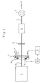
- the drive system of a motor vehicle shown in FIG. 1, e.g. of a passenger car, has as a drive unit an internal combustion engine 1, in which it for example a four-cylinder four-stroke Otto or is a diesel engine.
- the combustion engine 1 generated torque can be via a drive train 2 be transferred to drive wheels 3.
- In the drive direction is in the drive train 2 after the internal combustion engine 1 first an electrical one serving as a starter / generator Machine 4 arranged. This is followed by a driving clutch 5, a transmission 6 and an axle drive 7, which the Transmits torque to the drive wheels 3.
- the electric machine 4 - here a three-phase traveling field machine in asynchronous or synchronous design - comprises a stand 8 and a rotor 9.
- the former supports itself against the internal combustion engine 1, a (not shown) Vehicle chassis or a clutch housing (not shown) ab, whereas the latter directly on a Drive shaft (crankshaft) 10 of the internal combustion engine 1 or an extension of this sits and rotatably with this is coupled.
- the drive shaft 10 and the rotor 9 rotate here together, without the interposition of a transmission.
- the electrical machine 4 functions on the one hand as a generator for charging a vehicle battery and for supplying electrical consumer, thus replacing a conventional one Alternator in the vehicle.
- it acts as a starter of the internal combustion engine 1 starts in one run from the stand, and can thus also conventionally in a motor vehicle Replace the separately provided starter.
- the electric machine 4 is also equipped with a measuring device 15 for measuring speed and possibly also angle of rotation the runner 9 equipped.
- This consists of one fixed part 15a on an inner wall of a housing 16 of the electrical machine 4 is attached.
- the electrical machine 4 immediately behind the internal combustion engine 1 attached so that the fixed part 15a the measuring device 15 also directly on the outside of the housing Internal combustion engine 1 can be attached.
- the measuring device 15 consists of one rotating part, namely a measuring and heat dissipation fin 24 of an annular heat dissipation body 11 of the rotor 9.
- the measuring and heat dissipation rib 24 is in the following Simplification referred to as "measuring rib 24".
- the heat dissipation body 11 together with measuring rib 24 are made of aluminum. Further details on the measuring device 15 are given below described in connection with FIGS. 2, 3 and 5.
- an inverter is also shown schematically in FIG. 1 17 indicated, which the windings of the stator 8 of the electrical machine 4 at a clock frequency from approx. 10 kHz-100 kHz sine-weighted pulse width modulated Delivers voltage pulses under the effect of Machine inductance essentially sinusoidal three-phase currents result in the windings of the stator 8.
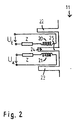
- the fixed part 15a of the measuring device 15 (which, according to FIGS. 1 and 5, is fastened on the inside of the housing of the electrical machine 4 and faces the rotor 9) has a transmitting coil 20 and a receiving coil 21 oriented essentially parallel at a distance therefrom .
- the transmitting coil 20 generates a high-frequency alternating magnetic field (measuring field), which induces a voltage corresponding to the alternating field in the receiving coil 21.
- Transmitting and receiving coils 20, 21 are therefore inductively coupled in the manner of a transformer. Instead of an iron core, which would be present in a transformer, however, the electromagnetic measuring field passes over the air gap between the transmitting and receiving coils 20, 21.
- a high-frequency, purely sinusoidal voltage is applied to the transmission coil 20.
- the frequency of the input voltage U E is, for example, 2 MHz and the signal amplitude is approximately 50 to 60 volts.
- the number of turns of transmitter coil 20 and receiver coil 21 are the same, for example 72 turns. This corresponds to a gear ratio of 1: 1.
- the amplitude of the voltage induced in the receiving coil 21 depends strongly (exponentially) on the width of the air gap. With a width of approx. 4 mm, in the present case the level of the output voltage U A in the receiver circuit is approx. 10 to 15 volts.
- an LC connection with coil and capacitor - that is, with an inductive and capacitive resistor Z - is carried out.
- the sinusoidal basic signal is then compared using this LC circuit.
- the measuring rib 24 is gem. Fig. 3 at one - the broadcast and Receiving coil 20, 21 facing - side of the heat dissipation body 11 arranged. It has about 30 to 50 on the side protruding teeth 25 on the entire circumference of the Heat dissipation body 11 are evenly distributed. Only at least one reference mark is used to determine the angle of rotation 25a provided in the form of an omitted tooth.
- the measuring rib 24 lies between two further annular ones Heat dissipation fins 22, 23 which are parallel to the measuring fin 24 the side of the heat dissipation body 11 over the entire circumference of the heat dissipation body are arranged progressively.
- the transmitter coil 20 is arranged between the measuring rib 24 and the outer of the cooling fins 22 and the receiving coil 21 between the inner of the cooling fins 23 and the measuring rib 24.
- This lies between the fixed transmission and reception coils 20, 21, with their teeth 25 projecting into the air gap between the transmission and reception coils 20, 21.
- the magnetic measuring field passing from the transmitting coil 20 to the receiving coil 21 is interrupted or at least weakened when the tooth 25 is in between; however, if there is a gap between two teeth, it will not be weakened.
- the rotation of the measuring rib 24 taking place with the rotor rotation then repeatedly leads to interruptions in the measuring field, which are measured as a fluctuation in the voltage U A induced in the receiving coil 21.
- This measurement signal is from the fixed part 15a of the measuring device 15 acc. 1 to an evaluation device 19.
- the magnetic generated by the transmitter coil 20 The measuring field is selected in a frequency range that significantly above the frequency range with the excitation currents the electric machine 4 fields associated therewith lies.
- the frequency of the measuring field is approx. 2 MHz, while the clock frequency of the previously described inverter 17 only about 10-100 kHz and the frequency of the sinusoidal Stator excitation currents is only approx. 1 kHz. Any interference signals resulting from this can therefore be due to of the different frequency ranges filtered and thus discriminates the measurement signals from any interference signals become.
- FIG. 4 shows the shape of the measurement signals received at the reception coil 21 and already filtered for interference. Due to the rotation of the measurement rib 24, the measurement field of the transmission coil 20 and thus the output voltage U A are amplitude-modulated: the amplitude maxima correspond to a full passage of the measurement field between the transmission and reception coils 20, 21, ie a tooth gap of the measuring rib 24, while at amplitude minima of the output signal U A , the measuring field between the transmitting and receiving coils 20, 21 strikes a tooth 25 and is therefore weakened.
- the number of maxima (or minima) of the measured output voltage U A per unit of time is a measure of the rotational speed of the electrical machine 4.
- the instantaneous rotation angle of the electrical machine 4 results from the distance between the measured voltage maxima (or voltage minima) and that at the measuring rib 24 provided tooth gap reference mark 25a.
- the determined values for speed and instantaneous angle of rotation and / or parameters derived therefrom such as angular velocity or angular acceleration are then z. B. like. 1 is output by the evaluation device 19 to the inverter 17.
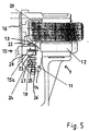
- the heat dissipation body 11 is at one - the fixed part 15a facing the measuring device 15 - Runner 9 side running over the entire circumference of the runner arranged.
- One - the fixed part 15a of the measuring device 15 facing away - side of a radially outer portion 13 of the heat dissipation body 11 is thermally conductive with an iron package 12 of the rotor 9 connected, in which the Most of the rotor's heat loss is generated.
- This is a second iron package 29 of the outside Stand 8 opposite.
- the heat dissipation fins 22, 23, the measuring fin 24, and others annular heat dissipation fins 25, 26 extend in equal distances from - the fixed part 15a of the Measuring device 15 facing - side of the heat dissipation body 11 outwards.
- the heat dissipation fins 22, 23, 25 and 26 and the heat dissipation body 11 are made in one piece.
- the measuring rib 24 is in one over the heat dissipation body circumference running recess in the heat dissipation body 11 used. In a further embodiment (not shown) is also the measuring rib 24 in one piece with the Heat dissipation body 11 made.
- the measuring rib 24 is in thermal contact the heat source of the runner 9 - here the iron package 12 - over the heat dissipation body 11.
- the heat dissipation fins 22, 23, 25 and 26 and the measuring rib 24 are flat; their extension in the longitudinal direction is therefore essential larger than their thickness.
- the fixed part 15a of the measuring device 15 and a fixed heat dissipation body 18, the heat dissipation body 11 of the rotor 9 is complementary, are thermally conductive with the housing 16 of the electrical machine 4 connected.
- Part 15a engages around measuring rib 24 pliers-shaped, with the transmitter coil in one pliers half 20 and in the other the receiving coil 21 is arranged.
- the second heat dissipation body 18 has annular ribs 27 on, which in the spaces between the heat dissipation fins 22, 23, 25 and 26 of the rotor 9 engage. Also the two pliers of part 15a of the measuring device 15 are ring-shaped, so they grip over the entire Circumference in the spaces between the measuring rib 24 and the adjacent heat dissipation lips 22 and 23. The active measuring part of the measuring device 15 is limited to one place on the circumference; the ring-shaped Extension of part 15a thus serves for heat transfer, is not necessary for the measurement.
- the heat transfer from the rotating part 11 to the fixed one Heat transfer part 18 is carried out without contact. Due to the small distances between the surfaces of the Ribs the two parts and the large area of the opposing Rib finishes despite the lack of direct heat conduction achieved a good heat transfer, and on the one hand through heat conduction and forced convection air between the fin surfaces, and on the other hand through heat radiation. With this type of "Non-contact heat conduction cooling” is not another Cooling of the rotor required. The one receiving the runner Interior of the electrical machine can therefore be complete encapsulated, without passage of cooling air or the like his. The heat conducted to the stand can e.g. by liquid cooling or by air cooling the Outer surface of the housing.
- the measuring rib 24 is fully in the heat transfer from Includes runners on the stand, so fulfills the claim 1 specified double function.
- Embodiments may include rotor fins 22, 23, 25 and 26 are omitted, the heat transfer alone ensures this the measuring rib 24 together with the part 15a of the measuring direction 15.
Abstract
Description
Die Erfindung betrifft eine elektrische Maschine, insbesondere einen Starter/Generator für ein Kraftfahrzeug.The invention relates to an electrical machine, in particular a starter / generator for a motor vehicle.
Drehwinkel- und Drehzahlmeßvorrichtungen und -verfahren sind für elektrische Maschinen bekannt. So werden z.B. bei Gleichstrommaschinen induktive Drehwinkelgeber, bei Drehstrom-Maschinen Drehtransformatoren (sog. Resolver) oder auch Inkrementalgeber verwendet.Angle of rotation and speed measuring devices and methods are known for electrical machines. For example, for DC machines inductive rotary encoder, at Three-phase machines Rotary transformers (so-called resolvers) or incremental encoder used.
Beispielsweise ist aus der DE 32 30 607 C2 eine Vorrichtung zum Messen der Drehzahl einer elektrischen Maschine bekannt. Hierbei ist an einem wicklungsfreien Läufer der elektrischen Maschine ein Zahnkranz angeordnet, dem ein elektromagnetischer Sensor zugeordnet ist. Dieser mißt den Momentanwert der Drehzahl, und gibt ihn an eine Steuervorrichtung aus. Aus der WO97/08456 ist ein Starter/Generator in Form einer Asynchronmaschine mit einem Revolver bekannt.For example, DE 32 30 607 C2 is a device for measuring the speed of an electrical machine known. Here is a non-winding runner electrical machine arranged a ring gear, the one is assigned to an electromagnetic sensor. This measures the instantaneous value of the speed, and sends it to a control device out. WO97 / 08456 is a starter / generator in the form of an asynchronous machine with a Revolver known.
Ferner ist es bekannt, zur Erhöhung der Kühlleistung bei elektrischen Maschinen einen oder mehrere Kühlkörper außen am Maschinengehäuse vorzusehen. Beispielsweise ist in dem Buch von G. Springer et al., "Fachkunde Elektrotechnik", Haan-Gruiten 1996, S. 329 eine elektrische Maschine beschrieben, an deren Gehäuseaußenfläche mehrere rippenförmige Kühlkörper angeordnet sind, die sich in Längsrichtung der elektrischen Maschine erstrecken. Aus der US-PS 4,958,095 ist es bekannt, zur Kühlung des Ständers einer als Starter/Generator dienenden elektrischen Maschine Luft durch das Innere der Maschine zu drücken. Hierdurch wird auch der Läufer gekühlt.It is also known to increase the cooling capacity electrical machines one or more heat sinks outside to be provided on the machine housing. For example, in the book by G. Springer et al., "Fachkunde Elektrotechnik", Haan-Gruiten 1996, p. 329 an electrical machine described, on the outer surface of the housing several rib-shaped Heat sinks are arranged, which are in the longitudinal direction of the electrical machine. From the US-PS 4,958,095 it is known for cooling the stand an electrical machine serving as a starter / generator To push air through the inside of the machine. This also cools the runner.
In der DE-OS 1513293 ist eine elektrische Maschine beschrieben, bei welcher ein Lüfterrad in Umfangsrichtung eingefräste Zähne aufweist. Diese dienen der Drehzahlerfassung. Zur Wärmeabfuhr sind am Lüfterrad separate Lamellen vorgesehen, die eine Kühlluftströmung erzeugen.An electrical machine is described in DE-OS 1513293, in which a fan wheel in the circumferential direction has milled teeth. These are used for speed detection. There are separate fins on the fan wheel for heat dissipation provided that generate a cooling air flow.
Der vorliegenden Erfindung liegt die Aufgabe zugrunde, eine verbesserte und mit verringertem Aufwand gestaltete elektrische Maschine, insbesondere zur Verwendung als Starter/Generator bei einem Kraftfahrzeug bereitzustellen.The present invention is based on the object an improved and designed with reduced effort electrical machine, especially for use as To provide starter / generator in a motor vehicle.
Die Erfindung erreicht dies durch den Gegenstand des Anspruchs
1. Weitere vorteilhafte Ausführungen der Erfindung
sind in den übrigen, abhängigen Ansprüchen beschrieben.The invention achieves this by the subject matter of the
Danach stellt die Erfindung eine elektrische Maschine mit Läufer und Ständer bereit, wobei der Läufer ein Wärmeabfuhrglied, insbesondere eine Wärmeabfuhrrippe aufweist,
- mit welchem Wärme vom Läufer zum Ständer hin abgeführt wird,
- und wobei das Wärmeabfuhrglied durch seine Drehung eine zeitliche Veränderung eines Meßsignals hervorruft, aus der der Drehwinkel und/oder die Drehzahl des Läufers relativ zum Ständer bestimmt wird.
- with which heat is dissipated from the rotor to the stand,
- and wherein the heat dissipation member causes a change in a measurement signal over time from which the angle of rotation and / or the rotational speed of the rotor relative to the stator is determined.
Es sind auch elektrische Maschinen mit zwei drehbaren Wirkeinheiten - also einem Läufer und einem drehbaren "Ständer" - bekannt (z. B. aus der DE 195 32 136 A1). Vorliegend soll der Begriff "Ständer" neben den üblichen feststehenden Ständern auch solche drehbaren Ständer umfassen.There are also two rotating electrical machines Knitting units - i.e. one runner and one rotatable "Stand" - known (z. B. from DE 195 32 136 A1). In the present case, the term "stand" should be used in addition to the usual fixed stands also include such rotatable stands.
Durch die Doppelfunktion des Wärmeabfuhrglieds als Wärmeabfuhr- und Drehbestimmungs-Bauteil ist die elektrische Maschine einfacher aufgebaut als eine entsprechende herkömmliche Maschine.Due to the double function of the heat dissipation element as a heat dissipation and rotation determination component, the electrical Machine constructed more simply than a corresponding conventional one Machine.
Bevorzugt bewirkt das Wärmeabfuhrglied die zeitliche Veränderung des Meßsignals durch Modulation eines Meßfelds. Alternativ ist z.B. auch denkbar, daß das Glied die zeitliche Veränderung des Meßsignals dadurch bewirkt, daß es selbst ein Meßfeld erzeugt. Z.B. kann das Glied als Permanentmagnet ausgestaltet sein, welcher aufgrund der Läuferdrehung ein zeitlich verändertes Meßsignal hervorruft, und welcher gleichzeitig Wärme vom Läufer zum Ständer hin abführt.The heat dissipation element preferably effects the change over time of the measurement signal by modulating a measurement field. Alternatively, e.g. also conceivable that the link the temporal Change in the measurement signal causes that itself creates a measuring field. E.g. can use the link as a permanent magnet be designed, which due to the rotor rotation causes a measurement signal that changes over time, and which at the same time heat from the runner to the stand dissipates.
Vorzugsweise weist die elektrische Maschine eine Einrichtung zum Erzeugen des Meßfeldes und eine zum Empfangen des Meßfelds auf, wobei das Wärmeabfuhrglied derart ausgebildet ist, daß es das Meßfeld bei der Drehung des Läufers verändert.The electrical machine preferably has a device to generate the measuring field and one to receive of the measuring field, the heat dissipation member being designed in this way is that it is the measuring field when the rotor rotates changed.
Das Wärmeabfuhrglied dreht sich bevorzugt gemeinsam mit dem Läufer. Das Glied und der Läufer können zweiteilig, aber einstückig verbunden sein. Denkbar ist auch, daß das Glied integraler Bestandteil des Läufers ist.The heat dissipation member preferably rotates together the runner. The link and the runner can be in two parts, but be connected in one piece. It is also conceivable that that Limb is an integral part of the runner.
Die Modulation des Meßfelds kann z.B. durch Transmission oder Reflexion bewirkt werden. Beispielsweise kann das Wärmeabfuhrglied bzw. die Wärmeabfuhrrippe ein Transponder sein, welcher das von der Meßfeld-Erzeugungseinrichtung erzeugte Meßfeld empfängt, und - geändert - wieder abstrahlt. Besonders bevorzugt ist das Glied ein passives Bauelement. Beispielsweise weist es Aussparungen oder reflektierende Stellen auf, um das Meßfeld zu modulieren.The modulation of the measuring field can e.g. through transmission or reflection. For example, that Heat dissipation member or the heat dissipation rib a transponder which is that of the measuring field generating device generated measuring field receives, and - changed - emits again. This is particularly preferred Link a passive component. For example, it points Cutouts or reflective spots around the measurement field to modulate.
Durch die Drehung des Glieds wird das Meßfeld in einer Weise verändert, daß durch diese Änderung der Drehwinkel und/oder die Drehzahl der elektrischen Maschine ermittelbar ist/sind. Hierzu ist das Glied vorzugsweise nahe bei der Einrichtung zum Erzeugen des Meßfeldes angeordnet, bzw. es gelangt im Verlauf der Läuferdrehung in deren Nähe.By rotating the link, the measuring field is in one Way changed that by this change in the angle of rotation and / or the speed of the electrical machine can be determined is / are. For this purpose the link is preferably close to the device for generating the measuring field is arranged, or it gets close to it in the course of the rotor rotation.
Um zugleich die Wärmeabfuhrfunktion für den Läufer zu erfüllen, besteht das Glied vorteilhaft aus einem Material mit hoher Wärmeleitfähigkeit. Ferner ist es vorteilhaft so ausgebildet, daß seine Oberfläche relativ groß im Verhältnis zum Volumen ist. Dies kann z.B. durch Kühllamellen oder -rippen erreicht werden, die im Querschnitt relativ dünn sind.In order to fulfill the heat dissipation function for the rotor at the same time, the link advantageously consists of one material with high thermal conductivity. It is also advantageous designed so that its surface area is relatively large in proportion to the volume. This can e.g. through cooling fins or ribs can be achieved, the cross-section relative are thin.
Die elektrische Maschine ist vorteilhaft eine Drehstrom-Maschine in Synchron- oder Asynchronbauart.The electrical machine is advantageously a three-phase machine in synchronous or asynchronous design.
Vorteilhaft ist die elektrische Maschine als kombinierter Starter für einen Kraftfahrzeug-Verbrennungsmotor und Generator des Kraftfahrzeuges ausgebildet. Besonders vorteilhaft handelt es sich um einen Kurbelwellen-Starter/Generator, also eine Maschine, die auf der Kurbelwelle des Verbrennungsmotors sitzt und permanent mit dieser dreht. Die Maschine kann mit gleicher Drehzahl wie der Verbrennungsmotor drehen oder, etwa durch Zwischenschaltung eines Planetengetriebes, über- oder untersetzt sein.The electrical machine is advantageous as a combined one Starter for a motor vehicle internal combustion engine and generator trained of the motor vehicle. Particularly advantageous is a crankshaft starter / generator, so a machine on the crankshaft of the internal combustion engine sits and permanently with this turns. The machine can run at the same speed as the internal combustion engine turn or, for example, by interposition a planetary gear, over or under his.
Die Erzeuger- und Empfängereinrichtungen für das Meßfeld sowie das Glied bzw. die Wärmeabfuhrrippe können zumindest teilweise im Bereich des drehmomenterzeugenden Magnetfeldes angeordnet sein. Bevorzugt ist dabei das Meßfeld mit einer charakteristischen Zeitabhängigkeit so gewählt, daß die Meßsignale - trotz etwaiger überlagerter vom drehmomenterzeugenden Feld der elektrischen Maschine herrührender Störsignale - in der Ermittlungseinrichtung identifiziert und herausgefiltert werden können. Selbst wenn die Störsignale die Meßsignale betragsmäßig um einige Größenordnungen übersteigen, unterscheiden sie sich z.B. in ihrer Frequenz und lassen sich deswegen diskriminieren.The generator and receiver devices for the measuring field and the link or the heat dissipation rib can at least partly in the area of the torque-generating magnetic field be arranged. The measuring field is preferred with a characteristic time dependency chosen so that the measurement signals - despite any superimposed from the torque-generating field of the electrical machine originating interference signals - in the detection device can be identified and filtered out. Self if the interference signals the measurement signals in amount by some Exceed orders of magnitude, they differ e.g. in their frequency and can therefore be discriminated against.
Das Meßfeld kann grundsätzlich jede Art von elektromagnetischem Feld sein, welches vorteilhaft durch die Einwirkung des Glieds als Wärmeabfuhr-Drehbestimmungs-Bauteil in seiner Amplitude, Frequenz und/oder Phase beeinflußt wird. Bevorzugt ist das Meßfeld ein hochfrequentes magnetisches Wechselfeld, das durch ein Sendemittel (z. B. eine Sendespule) erzeugt, von der Wärmeabfuhr-Drehbestimmungs-Glied beeinflußt, und über ein in geeigneter Weise abgestimmtes Empfangsmittel (z. B. einer Empfangsspule) empfangen wird. Denkbar sind aber auch Ausgestaltungen, bei denen an Stelle einer Kombination von Sende- und Empfangsspule etwa ein Fotoemitter und ein Fotodetektor zum Erzeugen und Empfangen eines optischen Signals eingesetzt werden.The measuring field can basically be any type of electromagnetic Field, which is advantageous by the action of the link as a heat dissipation rotation determination component influenced in its amplitude, frequency and / or phase becomes. The measuring field is preferably a high-frequency magnetic Alternating field generated by a transmitter (e.g. a Transmitter coil) generated by the heat dissipation rotation determination member influenced, and about an appropriate Receiving means coordinated in this way (e.g. a receiving coil) Will be received. However, configurations are also conceivable, where instead of a combination of Transmitting and receiving coils such as a photo emitter and a photo detector for generating and receiving an optical signal be used.
Bevorzugt weist das Wärmeabfuhr-Drehbestimmungs-Glied einen Modulator auf. Hierunter wird ein das Meßfeld mit der Läuferdrehung modulierender Teil des Glieds verstanden. Der übrige Teil des Wärmeabfuhr-Drehbestimmungs-Bauteils beeinflußt demgegenüber das Meßfeld nicht oder nur weniger stark mit der Läuferdrehung. Vorzugsweise sind beide Teile aus einem Stück gefertigt.The heat dissipation rotation determination element preferably has one Modulator on. Below this is the measuring field with the Understanding the rotor rotation modulating part of the limb. The remaining part of the heat dissipation rotation determination component on the other hand, does not affect the measuring field or only does so less strong with the rotor rotation. Both are preferred Parts made from one piece.
Das Glied besteht vorteilhaft aus einem Metall mit hoher Wärmeleitfähigkeit, insbesondere aus Aluminium. Vorzugsweise ist es im Aluminiumdruckgußverfahren gefertigt. The link advantageously consists of a metal with high Thermal conductivity, especially made of aluminum. Preferably it is manufactured using the aluminum die casting process.
Vorteilhaft ist der Modulator zwischen der Sendespule und der Empfangsspule angeordnet. Er moduliert dann die Transmission des Meßfeldes. Bei anderen Ausgestaltungen, die mit optischer Abtastung arbeiten, ist neben der Möglichkeit der Transmissionsmodulation auch diejenige einer Reflexionsmodulation besonders vorteilthaft. Der Modulator liegt vorteilhaft am äußeren Umfang oder einer Seite des Läufers. Vorzugsweise ist er ringförmig, konzentrisch zur Drehachse des Läufers.The modulator between the transmitter coil and is advantageous arranged the receiving coil. He then modulates the Transmission of the measuring field. In other configurations, who work with optical scanning is next to the possibility the transmission modulation also that of one Reflection modulation is particularly advantageous. The modulator is advantageously on the outer circumference or one side of the runner. It is preferably annular, concentric to the axis of rotation of the rotor.
Neben der oben beschriebenen Wärmeabfuhr-Drehbestimmungs-Rippe sind vorzugsweise weitere Wärmeübertragungsrippen vorgesehen, die kammartig mit komplementären Rippen des Ständers ineinander greifen.In addition to the heat dissipation rotation determination rib described above are preferably further heat transfer fins provided that comb-like with complementary ribs of the Stand interlocking.
Zum Modulieren des Meßfelds weist der Modulator vorteilhaft Aussparungen in Form von Löchern oder Zähnen auf. Hieraus wird in Kenntnis der Modulatorstruktur, z.B. der Anzahl der Zähne und der Lage etwaiger Bezugsmarken, beispielsweise in Form eines besonders ausgestalten oder ausgelassenen Zahns, der Drehwinkel und/oder die Drehzahl der elektrischen Maschine ermittelt und Größen, wie z.B. Winkelgeschwindigkeit oder Winkelbeschleunigung abgeleitet. Bei Reflexionsmodulation weist der Modulator abwechselnd Bereiche mit größerer und kleinerer Reflektivität auf.The modulator advantageously has for modulating the measuring field Cutouts in the form of holes or teeth. Knowing the modulator structure, e.g. the Number of teeth and the location of any reference marks, for example in the form of a specially designed or omitted tooth, the angle of rotation and / or the speed of the electrical machine and sizes, such as Derived angular velocity or angular acceleration. With reflection modulation, the modulator shows alternately Areas with greater and smaller reflectivity on.
Klarstellend sei angemerkt, daß das Wärmeabfuhr-Drehbestimmungs-Glied aus mehreren Einzelteilen, z. B. mehreren Wärmeübertragungsrippen oder Teilen hiervon zusammengesetzt sein kann.To clarify, it should be noted that the heat dissipation rotation determination member from several individual parts, e.g. B. several heat transfer fins or parts thereof can be.
Die Erfindung wird nun durch Ausführungsbeispiele und die angefügte beispielhafte Zeichnung näher erläutert. In der Zeichnung zeigen:
- Fig. 1
- eine unmaßstäblich-schematische Darstellung eines Antriebssystems mit einer elektrischen Maschine;
- Fig. 2
- eine unmaßstäblich-schematische Darstellung einer Drehbestimmungsvorrichtung der elektrischen Maschine;
- Fig. 3
- eine Draufsicht auf einen Ausschnitt eines Wärmeabfuhr-Drehbestirnmungs-Bauteils am Läufer der elektrischen Maschine;
- Fig. 4
- ein Diagramm eines störungsbereinigten Meßsignalverlaufs;
- Fig. 5
- einen Teilquerschnitt der elektrischen Maschine im Bereich des Umfangs des Läufers.
- Fig. 1
- a scale to schematic representation of a drive system with an electrical machine;
- Fig. 2
- a scale to schematic representation of a rotation determination device of the electrical machine;
- Fig. 3
- a plan view of a section of a heat dissipation-rotation determination component on the rotor of the electrical machine;
- Fig. 4
- a diagram of a noise-corrected measurement signal curve;
- Fig. 5
- a partial cross section of the electrical machine in the region of the circumference of the rotor.
Das in Fig. 1 dargestellte Antriebssystem eines Kraftfahrzeugs,
z.B. eines Personenkraftwages, weist als Antriebsaggregat
einen Verbrennungsmotor 1 auf, bei dem es
sich beispielsweise um einen Vierzylinder-Viertakt-Otto- oder
einen Dieselmotor handelt. Das vom Verbrennungsmotor
1 erzeugte Drehmoment kann über einen Antriebsstrang 2
auf Antriebsräder 3 übertragen werden. In Antriebsrichtung
ist im Antriebsstrang 2 nach dem Verbrennungsmotor 1
zunächst eine als Starter/Generator dienende elektrische
Maschine 4 angeordnet. Auf diese folgen eine Fahrkupplung
5, ein Getriebe 6 und ein Achsantrieb 7, welcher das
Drehmoment auf die Antriebsräder 3 überträgt.The drive system of a motor vehicle shown in FIG. 1,
e.g. of a passenger car, has as a drive unit
an
Die elektrische Maschine 4 - hier eine Drehstrom-Wanderfeldmaschine
in Asynchron- oder Synchron-Bauart -
umfaßt einen Ständer 8 und einen Läufer 9. Ersterer
stützt sich gegen den Verbrennungsmotor 1, ein (nicht gezeigtes)
Fahrzeugchassis oder ein (nicht gezeigtes) Kupplungsgehäuse
ab, wohingegen letzterer direkt auf einer
Triebwelle (Kurbelwelle) 10 des Verbrennungsmotors 1 oder
einer Verlängerung hiervon sitzt und mit dieser drehfest
gekoppelt ist. Die Triebwelle 10 und der Läufer 9 rotieren
hier gemeinsam, ohne Zwischenschaltung eines Getriebes.The electric machine 4 - here a three-phase traveling field machine
in asynchronous or synchronous design -
comprises a
Die elektrische Maschine 4 fungiert einerseits als Generator
zum Laden einer Fahrzeugbatterie und zum Versorgen
elektrischer Verbraucher, und ersetzt damit eine herkömmlicherweise
im Fahrzeug vorhandene Lichtmaschine. Andererseits
fungiert sie als Starter, der den Verbrennungsmotor
1 im Zusammenlauf aus dem Stand startet, und kann
somit auch einen herkömmlicherweise beim Kraftfahrzeug
gesondert vorgesehenen Starter ersetzen.The electrical machine 4 functions on the one hand as a generator
for charging a vehicle battery and for supplying
electrical consumer, thus replacing a conventional one
Alternator in the vehicle. On the other hand
it acts as a starter of the
Die elektrische Maschine 4 ist außerdem mit einer Meßvorrichtung
15 zum Messen von Drehzahl und ggf. auch Drehwinkel
des Läufers 9 ausgerüstet. Diese besteht aus einem
feststehenden Teil 15a, der an einer Innenwand eines Gehäuses
16 der elektrischen Maschine 4 angebracht ist. Bei
einer weiteren hier nicht dargestellten Variante ist die
elektrische Maschine 4 unmittelbar hinter dem Verbrennungsmotor
1 angebracht, so daß der feststehende Teil 15a
der Meßvorrichtung 15 auch direkt außen am Gehäuse des
Verbrennungsmotors 1 angebracht sein kann.The electric machine 4 is also equipped with a measuring
Desweiteren besteht die Meßvorrichtung 15 aus einem sich
drehenden Teil, und zwar einer Meß- und Wärmeabfuhrrippe
24 eines ringförmigen Wärmeabfuhrkörpers 11 des Läufers
9. Die Meß- und Wärmeabfuhrrippe 24 wird im folgenden zur
Vereinfachung als "Meßrippe 24" bezeichnet. Der Wärmeabfuhrkörper
11 samt Meßrippe 24 sind aus Aluminium ausgebildet.
Nähere Details zur Meßvorrichtung 15 werden unten
im Zusammenhang mit Fig. 2, 3 und 5 beschrieben.Furthermore, the measuring
Schließlich ist in Fig. 1 noch schematisch ein Wechselrichter
17 angedeutet, welcher den Wicklungen des Ständers
8 der elektrischen Maschine 4 bei einer Taktfrequenz
von ca. 10 kHz-100 kHz sinusbewertete pulsweitenmodulierte
Spannungsimpulse liefert, die unter der Wirkung der
Maschineninduktivität im wesentlichen sinusförmige Dreiphasenströme
in den Wicklungen des Ständers 8 ergeben.Finally, an inverter is also shown schematically in FIG. 1
17 indicated, which the windings of the
Gemäß Fig. 2 weist der feststehende Teil 15a der Meßvorrichtung
15 (der gemäß Fig. 1 und 5 innen am Gehäuse der
elektrischen Maschine 4 befestigt und dem Läufer 9 zugewandt
ist) eine Sendespule 20 und eine im Abstand davon im
wesentlichen parallel ausgerichtete Empfangsspule 21 auf.
Die Sendespule 20 erzeugt ein hochfrequentes magnetisches
Wechselfeld (Meßfeld), welches in der Empfangsspule 21 eine
dem Wechselfeld entsprechende Spannung induziert. Sende- und
Empfangsspule 20, 21 sind demnach nach Art eines Transformators
induktiv gekoppelt. Anstelle eines Eisenkernes,
der bei einem Transformator vorhanden wäre, tritt jedoch
das elektromagnetische Meßfeld über den zwischen Sende- und
Empfangsspule 20, 21 befindlichen Luftspalt. Die Sendespule
20 wird mit einer hochfrequenten, rein sinusförmigen Spannung
beaufschlagt. Die Frequenz der Eingangsspannung UE beträgt
z.B. 2 MHz und die Signalamplitude ca. 50 bis 60
Volt. Die Windungszahlen von Sendespule 20 und Empfangsspule
21 sind gleich, z.B. 72 Windungen. Dies entspricht einem
Übersetzungsverhältnis von 1:1. Die Amplitude der in der
Empfangsspule 21 induzierten Spannung hängt stark (exponentiell)
von der Breite des Luftspaltes ab. Bei einer Breite
von ca. 4 mm beläuft sich im vorliegenden Fall der Pegel
der Ausgangsspannung UA im Empfängerkreis auf ca. 10 bis 15
Volt. Um den Stromfluß sowohl im Schaltkreis der Sendespule
20 als auch im Schaltkreis der Empfangsspule 21 zu begrenzen,
wird eine LC-Beschaltung mit Spule und Kondensator -
also mit einem induktiven und kapazitiven Widerstand Z -
vorgenommen. Das sinusförmige Grundsignal wird dann über
diese LC-Beschaltung abgeglichen.According to FIG. 2, the
Die Meßrippe 24 ist gem. Fig. 3 an einer - der Sende- und
Empfangsspule 20, 21 zugewandten - Seite des Wärmeabfuhrkörpers
11 angeordnet. Sie weist ca. 30 bis 50 seitlich
vorstehende Zähne 25 auf, die über dem gesamten Umfang des
Wärmeabfuhrkörpers 11 gleichmäßig verteilt sind. Lediglich
für die Bestimmung des Drehwinkels ist mindestens eine Bezugsmarke
25a in Form eines ausgelassen Zahnes vorgesehen.
Die Meßrippe 24 liegt zwischen zwei weiteren ringförmigen
Wärmeabfuhrrippen 22, 23, die parallel zur Meßrippe 24 an
der Seite des Wärmeabfuhrkörpers 11 über den gesamten Wärmeabfuhrkörperumfang
verlaufend angeordnet sind.The measuring
Gem. Fig. 2 ist die Sendespule 20 zwischen der Meßrippe 24
und der äußeren der Kühlrippen 22 und die Empfangsspule 21
zwischen der inneren der Kühlrippen 23 und der Meßrippe 24
angeordnet. Diese liegt zwischen den feststehenden Sende- und
Empfangsspulen 20, 21, wobei ihre Zähne 25 in den
Luftspalt zwischen der Sende- und Empfangsspule 20, 21 hineinragen.
Auf diese Weise wird das von der Sendespule 20
zur Empfangsspule 21 übertretende magnetische Meßfeld bei
dazwischenliegendem Zahn 25 unterbrochen oder zumindest abgeschwächt;
wenn jedoch eine Lücke zwischen zwei Zähnen dazwischenliegt,
wird es nicht abgeschwächt. Die mit der Läuferdrehung
erfolgende Drehung der Meßrippe 24 führt dann
wiederholt zu Unterbrechungen des Meßfeldes, welche als
Schwankung der in der Empfangsspule 21 induzierten Spannung
UA gemessen werden. Dieses Meßsignal wird vom feststehenden
Teil 15a der Meßvorrichtung 15 gem. Fig. 1 zu einer Auswerteeinrichtung
19 übertragen.2, the
Trotz der räumlichen Nähe der Meßvorrichtung 15 zum Ständer
8 und Läufer 9 und damit zu dem starken drehmomenterzeugenden
Feld von Ständer 8 und Läufer 9 ist in der Auswerteeinrichtung
19 eine störsichere Ermittlung z.B. von Drehzahl
und Momentandrehwinkel der elektrischen Maschine 4 gewährleistet:
Das durch die Sendespule 20 erzeugte magnetische
Meßfeld ist nämlich in einem Frequenzbereich gewählt, der
erheblich oberhalb des Frequenzbereiches der mit den Erregerströmen
der elektrischen Maschine 4 einhergehenden Feldern
liegt. Die Frequenz des Meßfeldes beträgt ca. 2 MHz,
während die Taktfrequenz des zuvor beschriebenen Wechselrichters
17 nur ca. 10-100 kHz und die Frequenz der sinusförmigen
Ständer-Erregerströme nur ca. 1 kHz beträgt.
Etwaige hieraus resultierende Störsignale können daher aufgrund
der unterschiedlichen Frequenzbereiche gefiltert und
somit die Meßsignale von etwaigen Störsignalen diskriminiert
werden.Despite the spatial proximity of the measuring
Die Form der an der Empfangsspule 21 erhaltenen und bereits
störungsgefilterten Meßsignale zeigt Fig. 4. Aufgrund der
Drehung der Meßrippe 24 wird das Meßfeld der Sendespule 20
und damit die Ausgangsspannung UA amplitudenmoduliert: Die
Amplitudenmaxima entsprechen einem vollen Durchlaß des Meßfeldes
zwischen Sende- und Empfangsspule 20, 21, d.h. einer
Zahnlücke der Meßrippe 24, während bei Amplitudenminima des
Ausgangssignals UA, das Meßfeld zwischen Sende- und Empfangsspule
20, 21 auf einen Zahn 25 trifft und daher abgeschwächt
wird. Die Anzahl der Maxima (oder Minima) der gemessenen
Ausgangsspannung UA pro Zeiteinheit ist ein Maß
für die Drehzahl der elektrischen Maschine 4. Der Momentandrehwinkel
der elektrischen Maschine 4 ergibt sich aus dem
Abstand der gemessenen Spannungsmaxima (oder Spannungsminima)
zu der an der Meßrippe 24 vorgesehenen Zahnlückenbezugsmarke
25a. Die ermittelten Werte für Drehzahl und Momentandrehwinkel
und/oder daraus abgeleitete Kenngrößen wie
Winkelgeschwindigkeit oder Winkelbeschleunigung werden dann
z. B. gern. Fig. 1 von der Auswerteeinrichtung 19 an den
Wechselrichter 17 ausgegeben.FIG. 4 shows the shape of the measurement signals received at the
Gemäß Fig. 5 ist der Wärmeabfuhrkörper 11 an einer - dem
feststehende Teil 15a der Meßvorrichtung 15 zugewandten -
Seite des Läufers 9 über den gesamten Läuferumfang verlaufend
angeordnet. Eine - dem feststehende Teil 15a der Meßvorrichtung
15 abgewandte - Seite eines radial äußeren Abschnitts
13 des Wärmeabfuhrkörpers 11 ist wärmeleitend mit
einem Eisenpaket 12 des Läufers 9 verbunden, in dem der
größte Teil der läuferseitigen Verlustwärme entsteht. Diesem
liegt außenumfänglich ein zweites Eisenpaket 29 des
Ständers 8 gegenüber.5, the
Die Wärmeabfuhrrippen 22, 23, die Meßrippe 24, und weitere
ringförmige Wärmeabfuhrrippen 25, 26 erstrecken sich in
gleichen Abständen von der - dem feststehende Teil 15a der
Meßvorrichtung 15 zugewandten - Seite des Wärmeabfuhrkörpers
11 nach außen. Die Wärmeabfuhrrippen 22, 23, 25 und 26
und der Wärmeabfuhrkörper 11 sind aus einem Stück gefertigt.
Die Meßrippe 24 ist in eine über den Wärmeabfuhrkörperumfang
verlaufende Aussparung im Wärmeabfuhrkörper 11
eingesetzt. Bei einer weiteren (nicht dargestellten) Ausgestaltung
ist auch die Meßrippe 24 aus einem Stück mit dem
Wärmeabfuhrkörper 11 hergestellt. Bei allen möglichen Ausgestaltungen
steht die Meßrippe 24 in Wärmeleitungskontakt
der Verlustwärmequelle des Läufers 9 - hier dem Eisenpaket
12 - über den Wärmeabfuhrkörper 11. Die Wärmeabfuhrrippen
22, 23, 25 und 26 und die Meßrippe 24 sind flach ausgebildet;
ihre Erstreckung in Längsrichtung ist also wesentlich
größer als ihre Dicke.The
Der feststehende Teil 15a der Meßvorrichtung 15 und ein
feststehender Wärmeabfuhrkörper 18, der zum Wärmeabfuhrkörper
11 des Läufers 9 komplementär ausgebildet ist,
sind wärmeleitend mit dem Gehäuse 16 der elektrischen Maschine
4 verbunden. Der Teil 15a umgreift die Meßrippe 24
zangenförmig, wobei in einer Zangenhälfte die Sendespule
20 und in dem anderen die Empfangsspule 21 angeordnet ist.The
Der zweite Wärmeabfuhrkörper 18 weist ringförmige Rippen
27 auf, die in die Zwischenräume zwischen den Wärmeabfuhrrippen
22, 23, 25 und 26 des Läufers 9 eingreifen.
Auch die beiden Zangen des Teils 15a der Meßvorrichtung
15 sind ringförmig ausgebildet, greifen also über den gesamten
Umfang in die Zwischenräume zwischen der Meßrippe
24 und den benachbarten Wärmeabfuhrippen 22 und 23 ein.
Der meßtechnisch aktive Teil der Meßvorrichtung 15 ist
auf eine Stelle des Umfangs beschränkt; die ringförmige
Erstreckung des Teils 15a dient also der Wärmeübertragung,
ist aber für die Messung nicht erforderlich.The second
Die Wärmeübertragung vom drehenden Teil 11 auf den feststehenden
Wärmeübertragungsteil 18 erfolgt berührungsfrei.
Durch die geringen Abstände zwischen den Oberflächen der
Rippen der beiden Teile und die große Fläche der sich gegenüberstehenden
Rippenoberflächen wird trotz der fehlenden
direkten Wärmeleitung ein guter Wärmeübergang erzielt, und
zwar einerseits durch Wärmeleitung und Zwangskonvektion der
zwischen den Rippenoberflächen befindlichen Luft, und andererseits
durch Wärmestrahlung. Bei dieser Art von
"berührungsfreien Wärmeleitungskühlung" ist keine weitere
Kühlung des Läufers erforderlich. Der den Läufer aufnehmende
Innenraum der elektrischen Maschine kann daher vollständig
gekapselt, ohne Durchtritt von Kühlluft o. ä., ausgebildet
sein. Die zum Ständer geleitete Wärme kann z.B.
durch eine Flüssigkeitskühlung oder durch Luftkühlung der
Gehäuseaußenfläche abgeführt werden.The heat transfer from the
Die Meßrippe 24 ist dabei voll in die Wärmeübertragung vom
Läufer auf den Ständer einbezogen, erfüllt also die im Anspruch
1 angegebene Doppelfunktion. Bei (nicht gezeigten)
Ausführungsformen können die Läufer-Kühlrippen 22, 23, 25
und 26 entfallen, für die Wärmeübertragung sorgt hier allein
die Meßrippe 24 zusammen mit dem Teil 15a der Meßrichtung
15.The measuring
Claims (10)
mit Läufer (8) und Ständer (9), wobei der Läufer (8) ein Wärmeabfuhrglied (24), insbesondere eine Wärmeabfuhrrippe, aufweist,
with rotor (8) and stand (9), the rotor (8) having a heat dissipation element (24), in particular a heat dissipation fin,
Applications Claiming Priority (2)
| Application Number | Priority Date | Filing Date | Title |
|---|---|---|---|
| DE19913656 | 1999-03-25 | ||
| DE19913656A DE19913656C1 (en) | 1999-03-25 | 1999-03-25 | Electrical machine, in particular starter / generator for a motor vehicle |
Publications (1)
| Publication Number | Publication Date |
|---|---|
| EP1039617A1 true EP1039617A1 (en) | 2000-09-27 |
Family
ID=7902436
Family Applications (1)
| Application Number | Title | Priority Date | Filing Date |
|---|---|---|---|
| EP00106348A Withdrawn EP1039617A1 (en) | 1999-03-25 | 2000-03-23 | Electrical machine, in particular starter-generator for a motor vehicle |
Country Status (2)
| Country | Link |
|---|---|
| EP (1) | EP1039617A1 (en) |
| DE (1) | DE19913656C1 (en) |
Families Citing this family (2)
| Publication number | Priority date | Publication date | Assignee | Title |
|---|---|---|---|---|
| DE10201601C1 (en) | 2002-01-16 | 2003-06-05 | Audi Hungaria Motor Kft | Internal combustion engine with crankshaft in crankcase, has starter/generator rotor formed on crankshaft in axial position of balance weight(s) or crank web, stator fixed relative to crankcase |
| DE10227528A1 (en) * | 2002-06-20 | 2004-01-08 | Daimlerchrysler Ag | Rough running and misfire detection for internal combustion engine involves determining of values sine and cosine functions dependent on drive shaft position, forming arc tan value and evaluating |
Citations (8)
| Publication number | Priority date | Publication date | Assignee | Title |
|---|---|---|---|---|
| DE1513293A1 (en) * | 1965-07-12 | 1969-12-04 | Licentia Gmbh | Asynchronous motor controlled in its speed by pulses, which works together with a pulse generator |
| DE2312334A1 (en) * | 1973-03-09 | 1974-09-26 | Indur Antriebstechnik Ag | CLOSED ASYNCHRONOUS ELECTRIC MOTOR |
| DE3230607A1 (en) * | 1982-08-18 | 1984-02-23 | Volkswagenwerk Ag | Drive arrangement having an internal-combustion engine which produces a torque having a level of non-uniformity |
| US5070264A (en) * | 1989-09-16 | 1991-12-03 | Arthur Pfeiffer Vakuumtechnik Wetzlar Gmbh | Position sensor |
| US5381358A (en) * | 1991-04-12 | 1995-01-10 | Sony Corporation | Cyclic digital filter |
| FR2711283A1 (en) * | 1993-10-13 | 1995-04-21 | Valeo Equip Electr Moteur | Vehicle alternator with enhanced cooling |
| US5717262A (en) * | 1993-10-20 | 1998-02-10 | J.M. Voith Gmbh | Cooling apparatus for an AC generator |
| US5744880A (en) * | 1995-06-20 | 1998-04-28 | Hitachi, Ltd. | Rotating motor and motor-driven vehicle |
Family Cites Families (2)
| Publication number | Priority date | Publication date | Assignee | Title |
|---|---|---|---|---|
| DE19532136A1 (en) * | 1995-08-31 | 1997-03-06 | Clouth Gummiwerke Ag | Drive system, in particular for a motor vehicle, and method for operating the same |
| DE59603588D1 (en) * | 1995-08-31 | 1999-12-09 | Isad Electronic Sys Gmbh & Co | DRIVE SYSTEM WITH DRIVE MOTOR, ELECTRICAL MACHINE AND BATTERY |
-
1999
- 1999-03-25 DE DE19913656A patent/DE19913656C1/en not_active Expired - Fee Related
-
2000
- 2000-03-23 EP EP00106348A patent/EP1039617A1/en not_active Withdrawn
Patent Citations (8)
| Publication number | Priority date | Publication date | Assignee | Title |
|---|---|---|---|---|
| DE1513293A1 (en) * | 1965-07-12 | 1969-12-04 | Licentia Gmbh | Asynchronous motor controlled in its speed by pulses, which works together with a pulse generator |
| DE2312334A1 (en) * | 1973-03-09 | 1974-09-26 | Indur Antriebstechnik Ag | CLOSED ASYNCHRONOUS ELECTRIC MOTOR |
| DE3230607A1 (en) * | 1982-08-18 | 1984-02-23 | Volkswagenwerk Ag | Drive arrangement having an internal-combustion engine which produces a torque having a level of non-uniformity |
| US5070264A (en) * | 1989-09-16 | 1991-12-03 | Arthur Pfeiffer Vakuumtechnik Wetzlar Gmbh | Position sensor |
| US5381358A (en) * | 1991-04-12 | 1995-01-10 | Sony Corporation | Cyclic digital filter |
| FR2711283A1 (en) * | 1993-10-13 | 1995-04-21 | Valeo Equip Electr Moteur | Vehicle alternator with enhanced cooling |
| US5717262A (en) * | 1993-10-20 | 1998-02-10 | J.M. Voith Gmbh | Cooling apparatus for an AC generator |
| US5744880A (en) * | 1995-06-20 | 1998-04-28 | Hitachi, Ltd. | Rotating motor and motor-driven vehicle |
Also Published As
| Publication number | Publication date |
|---|---|
| DE19913656C1 (en) | 2001-01-18 |
Similar Documents
| Publication | Publication Date | Title |
|---|---|---|
| EP3645977B1 (en) | Sensor system for determining at least one rotation characteristic of a rotating element | |
| EP2572114B1 (en) | Rolling bearing having an integrated generator | |
| DE10060287A1 (en) | Determination of the angle, angular velocity, and or torque of a rotating body, especially a motor vehicle steering wheel shaft by use of optical code traces on the rotating body and optical sensors for reading a code offset | |
| DE4119834A1 (en) | METHOD FOR GENERATING ELECTRICAL ENERGY BY MEANS OF A GENERATOR, AND USE IN VEHICLES WITH ANTI-SLIDING SYSTEM | |
| DE3713304A1 (en) | DEVICE FOR DETECTING TURNING ANGLE POSITION IN ROTARY DRIVES | |
| EP3555571B1 (en) | Sensor system for determining at least one rotation property of an element rotating about at least one rotational axis | |
| DE3831248A1 (en) | TURNING ANGLE ARRANGEMENT | |
| DE102012200195A1 (en) | position sensor | |
| EP1824689A1 (en) | Transmission system for tire state quantities | |
| DE102018113378A1 (en) | Load measuring method, load measuring device and load measuring arrangement as well as drive control and e-bike | |
| DE2460772A1 (en) | ANTI-LOCKING DEVICE FOR A MOTOR VEHICLE AND FOR USE IN SUCH A SPECIFIC WHEEL SPEED SENSOR | |
| DE4213977A1 (en) | DEVICE FOR MEASURING ROTATIONAL MOTIONS | |
| DE69824059T2 (en) | Resolver with loss flux absorber | |
| DE2934085C2 (en) | ||
| DE4229569C1 (en) | Machine tool with telemetry monitoring system for tool shaft - uses sensor element attached to shaft and coupled to amplifier on outside of housing half shell enclosing shaft | |
| DE19758037A1 (en) | Coder for position and measuring sensor for automobile ignition system | |
| EP1039617A1 (en) | Electrical machine, in particular starter-generator for a motor vehicle | |
| EP0513251A1 (en) | Device for determining the absolute position of a component moving along a predetermined path | |
| DE19646056C2 (en) | Device for measuring the speed of a body rotating about an axis of rotation | |
| EP0907891A1 (en) | Arrangement for the contactless inductive transmission of electric measurement values and/or electric energy between a rotor and a stator | |
| DE69618427T2 (en) | measuring system | |
| DE19800380C2 (en) | Inductive angle measuring device | |
| DE102021131033B3 (en) | Sensor arrangement and electrical machine | |
| WO2016184903A1 (en) | Damper device comprising a magnetorheological damper | |
| EP3975211B1 (en) | Unification of resolver and inductive rotor supply in one magnetic circuit |
Legal Events
| Date | Code | Title | Description |
|---|---|---|---|
| PUAI | Public reference made under article 153(3) epc to a published international application that has entered the european phase |
Free format text: ORIGINAL CODE: 0009012 |
|
| AK | Designated contracting states |
Kind code of ref document: A1 Designated state(s): AT BE CH CY DE DK ES FI FR GB GR IE IT LI LU MC NL PT SE |
|
| AX | Request for extension of the european patent |
Free format text: AL;LT;LV;MK;RO;SI |
|
| RAP1 | Party data changed (applicant data changed or rights of an application transferred) |
Owner name: CONTINENTAL ISAD ELECTRONIC SYSTEMS GMBH & CO. OHG |
|
| AKX | Designation fees paid | ||
| STAA | Information on the status of an ep patent application or granted ep patent |
Free format text: STATUS: THE APPLICATION IS DEEMED TO BE WITHDRAWN |
|
| 18D | Application deemed to be withdrawn |
Effective date: 20010328 |
|
| REG | Reference to a national code |
Ref country code: DE Ref legal event code: 8566 |