EP1040791A1 - Tibial cutting guide with adjustment handgrip - Google Patents
Tibial cutting guide with adjustment handgrip Download PDFInfo
- Publication number
- EP1040791A1 EP1040791A1 EP00400843A EP00400843A EP1040791A1 EP 1040791 A1 EP1040791 A1 EP 1040791A1 EP 00400843 A EP00400843 A EP 00400843A EP 00400843 A EP00400843 A EP 00400843A EP 1040791 A1 EP1040791 A1 EP 1040791A1
- Authority
- EP
- European Patent Office
- Prior art keywords
- tibia
- relative
- proximal
- cutting guide
- stem
- Prior art date
- Legal status (The legal status is an assumption and is not a legal conclusion. Google has not performed a legal analysis and makes no representation as to the accuracy of the status listed.)
- Granted
Links
- 210000002303 tibia Anatomy 0.000 claims abstract description 51
- 230000000903 blocking effect Effects 0.000 claims description 8
- 241001227561 Valgus Species 0.000 claims description 6
- 241000469816 Varus Species 0.000 claims description 6
- 210000003811 finger Anatomy 0.000 description 17
- 238000002271 resection Methods 0.000 description 9
- 210000003813 thumb Anatomy 0.000 description 3
- 230000005540 biological transmission Effects 0.000 description 2
- 230000000295 complement effect Effects 0.000 description 2
- 210000000988 bone and bone Anatomy 0.000 description 1
- 238000006073 displacement reaction Methods 0.000 description 1
- 230000003100 immobilizing effect Effects 0.000 description 1
- 238000007373 indentation Methods 0.000 description 1
- 210000003127 knee Anatomy 0.000 description 1
- 238000004519 manufacturing process Methods 0.000 description 1
- 239000000523 sample Substances 0.000 description 1
Images

Classifications
-
- A—HUMAN NECESSITIES
- A61—MEDICAL OR VETERINARY SCIENCE; HYGIENE
- A61B—DIAGNOSIS; SURGERY; IDENTIFICATION
- A61B17/00—Surgical instruments, devices or methods, e.g. tourniquets
- A61B17/14—Surgical saws ; Accessories therefor
- A61B17/15—Guides therefor
- A61B17/154—Guides therefor for preparing bone for knee prosthesis
- A61B17/157—Cutting tibia
Definitions
- the present invention relates to a device for positioning of a proximal end of a tibia by input to a cutting guide, the cutting guide can then guide a saw blade for resection of the next tibia a given resection plan, to allow the establishment a knee prosthesis.
- Positioning devices of this kind are already known in the prior art. It generally includes a gallows, means of distal immobilization of the tibia intended to immobilize the distal end of the tibia in a given position, these distal immobilization means being sliding mounted on the stem, with possibility of blocking, in at least one direction, preferably two perpendicular directions, in a plane perpendicular to the gallows, means of proximal immobilization of the tibia, intended to immobilize the proximal end of the tibia in a given position and being slidably mounted along the stem and a cutting guide mounted on the stem.
- the chosen resection plan takes into account the inclination of the tibia in the anteroposterior plane or sagittal, and the inclination of the tibia in the frontal plane (varus-valgus). It is therefore necessary, when one positions the cutting guide relative to the tibia to be able to adjust the angle formed between the stem and the tibia in the sagittal plane (posterior slope) and the angle formed between the gallows and the tibia in the plane frontal (varus-valgus).
- these prior art devices consist of a large number of complicated and difficult-to-assemble assembly components manipulate.
- the invention aims to overcome these drawbacks, and in particular a positioning device of the kind described previously which is easier to take and handle, especially when adjusting the inclinations of the tibia by relation to the gallows in the frontal and sagittal planes and the height of the cutting guide relative to the tibia.
- the device for positioning of a proximal end of a tibia by compared to a cutting guide is characterized in that it features a pistol grip having a dog and a trigger and attached to the gallows and whose dog acts on means for adjusting the relative position of the means of immobilization proximal to the gallows with the possibility of blocking and the detent acting on means for adjusting the angle (slope posterior) between the gallows and the tibia in the plane sagittal.
- the device allows the surgeon a setting simple position of the shin relative to the cutting guide.
- the positioning of the immobilization means proximal is done simply by soliciting the dog and by sliding these means along the stem, then, once the right position has been found, by releasing the dog, which blocks in position the immobilization means proximal, with the chosen resection plane opposite the guide cutting. Then, we activate the trigger which allows adjust the posterior slope of the tibia then release the trigger to block the set value of the slope posterior and then using the handle, without pressing neither on the dog, nor on the trigger, we regulate by sliding in the frontal plane the angle of varus-valgus.
- the means for adjusting the angle between the tibia and the gallows in the sagittal plane consist of a lever of which one end cooperates with a pushing piece the lower end of which has serrations which mesh with serrations of a support arm, the action push on the trigger causing the exit of the meshing of the piece's serrations with the serrations and the relaxation of the trigger the meshing of these same serrations in the second push piece with the arm serrations, so adjust the angle between the gallows and tibia in the sagittal plane.
- the device according to this improvement is simple to manufacture.
- the support arm has a plate sliding in a rail formed in a support of the distal immobilization means of the tibia, this sliding being carried out with possibility of locking by cooperation of a lug with recesses formed one after the other in the rail of guide, the recesses successively receiving the lug for a blockage of the plate relative to the means distal immobilization, thereby adjusting the angle between the shin and the gallows in the frontal plane (angle of varus / valgus).
- the means of proximal tibia immobilization include a rod which can slide in the stem, the rod comprising grooves, the grooves meshing with serrations a first pushing piece whose displacement is actuated by the dog, the push of the dog causing the outlet for indentation of the part with the grooves to allow the rod to slide by relation to the gallows and the relaxation of the support on the dog causing the serrations of the first push piece with grooves to block in position the rod relative to the stem, and therefore the means of proximal immobilization with respect to the tibia.
- the number of splines on the support arm corresponds to one setting range determined in advance of the slope angle posterior, for example between 0 ° and 8 °.
- the number of recesses in the guide rail corresponds to a setting range determined in advance of the angle of varus / valgus for example between -3 ° and 3 °.
- the cutting guide can slide, being locked in rotation, relative to the stem, in the direction height, regardless of the means of immobilization proximal. This allows for even finer adjustment of the position of the cutting guide, and consequently of the position tibial resection.
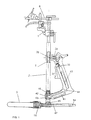
- the positioning device of a proximal end of a tibia (not shown) by compared to a cutting guide 1 has a stem 2 cylindrical oblong.
- a clamp 3 consisting of two forks 3A, 3B intended to grip the malleolus of the tibia articulated to a support 55 and two springs 4A, 4B stressing the two forks so as to tighten the malleolus is mounted on the gallows 2 so that it can slide perpendicular to the plane with the tibia and the gallows (the sagittal plane).
- the hollow oblong stem 2 receives a sliding rod 5 in the upper part of the gallows 2.
- This sliding rod 5 comprises at its lower end of the grooves 6 which will be described later allow positioning with locking the rod 5 relative to the stem 2.
- the upper part of the rod 5 comprises a bore 7 of cross section rectangular which receives a sliding fixing finger 8 in this bore 7 and which can be blocked by a screw 9 in a chosen position.
- the fixing finger 8 has a cylindrical bore 10 receiving a captive nail 11 intended to be plugged into the proximal part tibia, especially in the spine mass of the tibia.
- a another bore 12 is also provided for another spindle or nail.
- Two crossing recesses 13 and 14 are formed in finger 8, in order to lighten the finger and therefore the whole of the device.
- a cutting guide support 15 can slide on the upper part of the rod 5.
- the support 15 includes a bore 16 through which the rod 5 passes and by which the support 15 can slide on this rod 5.
- a screw 17 allows the blocking in the desired position of the support 15 cutting guide on the rod 5.
- the rotation of the support 15 relative to the longitudinal axis of the rod 5 is prevented by providing at the level of the rod 5 where can slide the support 15 a longitudinal groove 25 and a lug in the support 15, which thus prevents a rotation of the support 15 relative to the rod 5.
- the guide section 1 is fixed to the support 15 in a simple manner, by example by the cooperation of a tab 19 with a bore 20 of the section shape cutting guide additional transverse, with separable snap-in, and for this purpose the tongue 19 has a transverse orifice 21 for receiving a hollow rod containing a spring which outwardly requests a retaining ball intended for come and stay in a corresponding notch in the surface of the bore 20 of the cutting guide. So, as well for mounting the cutting guide on the tongue only for disassembly, just move these two manually elements relative to each other by forcing the ball towards inside the orifice 21, this ball emerging from itself either when the two elements are separated, or when the cutting guide is inserted in the tab 19.
- the cutting guide cut has in its upper part a probe assembly removable comprising a body 22, a feeler finger 23 and a column 24.
- Column 24 is inserted in guide 1 of cut in a bore 26 left or 27 right.
- a system ball locking may be provided.
- Body 22 slides on the column 24 by means of a bore 28, while the probing finger 23 slides in a bore 29 transverse to bore 28.
- the sliding of the body 22 on the column 24 can be carried out without mutual rotation, the cross section of the bore 28 being certainly circular, complementary to that of column 24, but the cooperation of finger 23 with the opening 30 prevents rotation of the body 22.
- the sliding of the finger 23 is carried out without possible rotation, the cross section of the bore 29 being square, as that of finger 23.
- the cutting guide 1 conventionally comprises a saw blade counter guiding system or a slot 31 for the passage of a saw blade.
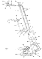
- a handle 32 of revolver This revolver handle 32 includes in its upper part a dog 33 articulated to an axis of rotation 34, the dog 33 cooperating with a spring 35 which urges a first pushing part 36 whose proximal end in spring 35 has rack teeth which can engage in the grooves 6 of the rod 5.
- the handle 32 revolver also includes a trigger 37 articulated by relative to an axis of rotation 38.
- a spring 39 biases the trigger 37 by exerting a return torque in relation to the axis 38.
- the trigger 37 cooperates with a lever 40 disposed at inside the handle 32.
- This lever 40 is bent at comprising two branches, a first branch which cooperates with trigger 37, while its second branch 41 penetrates through its end 42 into a transverse bore 43 of the gallows 2, in its lower part.
- Lever 40 is fixed mounted inside the handle 32, being articulated relative to an axis 44 at the level of the part where join the two arms of lever 40.
- the end 42 of the lever 40 cooperates with a second push piece 45 and a spring return 46, arranged in the bracket 2, being able to slide inside of it.
- the lower end of the second thrust piece 45 includes teeth racks which engage in grooves 47 of one arm support 48 which is oblong, of section transverse square and which slides in a bore 49 of the stem 2 in its lower part.
- Bore 49 is square cross section, complementary to the cross section transverse of the support arm 48.
- the sliding takes place in the medio-lateral plane.
- This support arm 48 comprises at one of its ends a guide plate 50 which can slide in a guide rail 51 formed in the support clamps 3A, 3B.
- the sliding of the guide plate 50 takes place in the plane perpendicular to the stem 2, in the direction perpendicular to the sliding direction of the support arm 48 in the bore 49.
- the outer face of the plate 50 (away from the bracket 2) has a lug 52 which can snap into a row of recesses 53 formed in the wall of the guide rail 51 on which is guided the plate 50.
- the lug 52 can snap into each recess 53 while being pushed there by a spring inside the support arm 48.
- Adjusting the position of the tibia relative to the cutting guide is carried out as follows: The user enters the positioning system by his handle 32 of revolver and grips the malleoli of the tibia by clamps 3A, 3B which fit tightly with the action of the return springs 4A, 4B. User presses then on the dog 33, with the thumb, the rotation in the clockwise from the dog 33 training the loosening of the spring 35 which brings with it the first pushing part 36, the teeth of part 36 then coming out of their meshing with the grooves 6. With its other hand, the user can then adjust the height of the rod 5 by sliding it in the stem 2.
- the user releases the dog 33 which, by means of the spring 35 repels the push piece 36 engaged by its serrations with the grooves 6 of the rod 5.
- the rod 5 is then blocked and does not can no longer be moved by sliding in the stem 2.
- the user then fixes the upper part of the tibia (mass of thorns) by the nail 11 captive, at the center of the tibia. He supports then on trigger 37.
- This trigger 37 acts on the first branch of lever 40 in link with this trigger 37 and causes the lifting of the second branch 41 of the lever 40, the end 42 of the second branch 41 of the lever 40 then driving towards the top the second push piece 45, the serration of which the lower end comes out of its mesh with the serrations 47 of the support arm 48.
- the support arm 48 can then slide in the bore 49, perpendicular to the bracket 2 and when the angle adjustment in the plane sagittal between the tibia held by its malleoli in the forks 3A, 3B and the stem 2 is carried to the value desired, the user releases trigger 37, which is returned to the free position by the return spring 39.
- the end 42 of the second branch 41 of the lever 40 then lowers and the teeth of the push piece 45 are engaged in the serrations 47 of the support arm 48.
- the posterior slope of the tibia was thus adjusted by compared to the gallows.
- the angle can be chosen between 0 ° and 8 °, by providing a number of teeth 47 sufficient for this adjustment range.
- we perform the angle adjustment varus / valgus in the frontal plane) by sliding the plate 50 in its rail 51, by moving the stem 2 by the handle 32 in the plane perpendicular to FIG. 1 (plane frontal).
- the pin 52 is placed in recess 53 in which it is then, by via a lever 54.
- the number of recesses 53 is provided to allow a setting of for example ⁇ 3 ° of the varus-valgus angle (plane frontal). Height adjustment, posterior slope and varus / valgus having been performed, we then set the probing finger 23 by sliding it over the column 24 to define the exact height of the resection plane. The resection can then be performed. We can then do slide the support 15 of the cutting guide to bring the probing finger 23 in contact with the bone to martialize precisely the resection plane and block the support 15 in position by screw 17.
- the dog and the trigger are both integrated to the handle.
- the user can press the dog with thumb and on the trigger with the index finger easily for all the relative positions of the immobilizing means proximal to the gallows.
- the trigger is independent of the handle and for certain relative positions of the immobilization means proximal to the stem, the user will not have the index long enough to act on the trigger while can simultaneously act on the dog with the thumb.
- means for transmitting the action of the finger on the trigger at the means for adjusting the angle between the gallows and the tibia these means of transmission not part of the gallows.
- these means of transmission consist of at least one lever which is located outside the gallows and in particular is located at inside the pistol grip.
Abstract
Description
La présente invention concerne un dispositif de mise en position d'une extrémité proximale d'un tibia par apport à un guide de coupe, le guide de coupe pouvant alors guider une lame de scie pour la résection du tibia suivant un plan de résection donné, pour permettre la mise en place d'une prothèse du genou.The present invention relates to a device for positioning of a proximal end of a tibia by input to a cutting guide, the cutting guide can then guide a saw blade for resection of the next tibia a given resection plan, to allow the establishment a knee prosthesis.
Les dispositifs de mise en position de ce genre sont déjà connus de l'art antérieur. Il comporte en général une potence, des moyens d'immobilisation distale du tibia destinés à immobiliser l'extrémité distale du tibia en une position donnée, ces moyens d'immobilisation distale étant montés coulissants sur la potence, avec possibilité de blocage, suivant au moins une direction, de préférence deux directions perpendiculaires, dans un plan perpendiculaire à la potence, des moyens d'immobilisation proximale du tibia, destinés à immobiliser l'extrémité proximale du tibia en une position donnée et étant montés coulissants le long de la potence et un guide de coupe monté sur la potence.Positioning devices of this kind are already known in the prior art. It generally includes a gallows, means of distal immobilization of the tibia intended to immobilize the distal end of the tibia in a given position, these distal immobilization means being sliding mounted on the stem, with possibility of blocking, in at least one direction, preferably two perpendicular directions, in a plane perpendicular to the gallows, means of proximal immobilization of the tibia, intended to immobilize the proximal end of the tibia in a given position and being slidably mounted along the stem and a cutting guide mounted on the stem.
Ces dispositifs de l'art antérieur présentent plusieurs inconvénients.These prior art devices have several disadvantages.
Le plan de résection choisi tient compte de l'inclinaison du tibia dans le plan antéro-postérieur ou sagittal, et de l'inclinaison du tibia dans le plan frontal (varus-valgus). Il est donc nécessaire, lorsque l'on positionne le guide de coupe par rapport au tibia immobilisé, de pouvoir régler l'angle formé entre la potence et le tibia dans le plan sagittal (pente postérieure) et l'angle formé entre la potence et le tibia dans le plan frontal (varus-valgus). Or, pour permettre ces réglages ainsi que celui de la hauteur du guide de coupe, ces dispositifs de l'art antérieur sont constitués d'un grand nombre de composants d'assemblage compliqués et difficiles à manipuler.The chosen resection plan takes into account the inclination of the tibia in the anteroposterior plane or sagittal, and the inclination of the tibia in the frontal plane (varus-valgus). It is therefore necessary, when one positions the cutting guide relative to the tibia to be able to adjust the angle formed between the stem and the tibia in the sagittal plane (posterior slope) and the angle formed between the gallows and the tibia in the plane frontal (varus-valgus). However, to allow these adjustments as well as the height of the cutting guide, these prior art devices consist of a large number of complicated and difficult-to-assemble assembly components manipulate.
L'invention vise à pallier ces inconvénients, et notamment un dispositif de mise en position du genre décrit précédemment qui soit plus simple à prendre et à manipuler, notamment lors du réglage des inclinaisons du tibia par rapport à la potence dans les plans frontal et sagittal et de la hauteur du guide de coupe par rapport au tibia.The invention aims to overcome these drawbacks, and in particular a positioning device of the kind described previously which is easier to take and handle, especially when adjusting the inclinations of the tibia by relation to the gallows in the frontal and sagittal planes and the height of the cutting guide relative to the tibia.
Suivant la présente invention, le dispositif de mise en position d'une extrémité proximale d'un tibia par rapport à un guide de coupe est caractérisé en ce qu'il comporte une poignée de pistolet ayant un chien et une détente et fixée à la potence et dont le chien agit sur des moyens qui permettent le réglage de la position relative des moyens d'immobilisation proximale par rapport à la potence avec possibilité de blocage et dont la détente agit sur des moyens qui permettent le réglage de l'angle (pente postérieure) entre la potence et le tibia dans le plan sagittal.According to the present invention, the device for positioning of a proximal end of a tibia by compared to a cutting guide is characterized in that it features a pistol grip having a dog and a trigger and attached to the gallows and whose dog acts on means for adjusting the relative position of the means of immobilization proximal to the gallows with the possibility of blocking and the detent acting on means for adjusting the angle (slope posterior) between the gallows and the tibia in the plane sagittal.
En prévoyant ainsi une poignée de pistolet à chien et détente, le dispositif permet au chirurgien une mise en position simple du tibia par rapport au guide de coupe. En effet, le positionnement des moyens d'immobilisation proximale s'effectue simplement en sollicitant le chien et en faisant coulisser ces moyens le long de la potence, puis, une fois la bonne position trouvée, en relâchant le chien, ce qui bloque en position les moyens d'immobilisation proximale, avec le plan de résection choisi en face du guide de coupe. Ensuite, on actionne la détente qui permet de régler la pente postérieure du tibia puis on relâche la détente pour bloquer la valeur réglée de la pente postérieure et ensuite à l'aide de la poignée, sans appuyer ni sur le chien, ni sur la détente, on règle par coulissement dans le plan frontal l'angle de varus-valgus.By thus providing a handle of dog pistol and relaxation, the device allows the surgeon a setting simple position of the shin relative to the cutting guide. In indeed, the positioning of the immobilization means proximal is done simply by soliciting the dog and by sliding these means along the stem, then, once the right position has been found, by releasing the dog, which blocks in position the immobilization means proximal, with the chosen resection plane opposite the guide cutting. Then, we activate the trigger which allows adjust the posterior slope of the tibia then release the trigger to block the set value of the slope posterior and then using the handle, without pressing neither on the dog, nor on the trigger, we regulate by sliding in the frontal plane the angle of varus-valgus.
Suivant un perfectionnement de l'invention, les moyens qui permettent un réglage de l'angle entre le tibia et la potence dans le plan sagittal sont constitués d'un levier dont une extrémité coopère avec une pièce de poussée dont l'extrémité inférieure comporte des dentelures qui engrènent avec des dentelures d'un bras de support, l'action de poussée sur la détente entraínant la sortie de l'engrènement des dentelures de la pièce avec les dentelures et le relâchement de la détente l'engrènement de ces mêmes dentelures de la seconde pièce de poussée avec les dentelures du bras, pour ainsi régler l'angle entre la potence et le tibia dans le plan sagittal. Le dispositif suivant ce perfectionnement est de fabrication simple.According to an improvement of the invention, the means for adjusting the angle between the tibia and the gallows in the sagittal plane consist of a lever of which one end cooperates with a pushing piece the lower end of which has serrations which mesh with serrations of a support arm, the action push on the trigger causing the exit of the meshing of the piece's serrations with the serrations and the relaxation of the trigger the meshing of these same serrations in the second push piece with the arm serrations, so adjust the angle between the gallows and tibia in the sagittal plane. The device according to this improvement is simple to manufacture.
Suivant un perfectionnement de l'invention, le bras support comporte une plaque coulissant dans un rail formé dans un support des moyens d'immobilisation distale du tibia, ce coulissement étant réalisé avec possibilité de blocage par coopération d'un ergot avec des évidements formés les uns à la suite des autres dans le rail de guidage, les évidements recevant successivement l'ergot pour un blocage de la plaque par rapport aux moyens d'immobilisation distale, pour ainsi régler l'angle entre le tibia et la potence dans le plan frontal (angle de varus/valgus).According to an improvement of the invention, the support arm has a plate sliding in a rail formed in a support of the distal immobilization means of the tibia, this sliding being carried out with possibility of locking by cooperation of a lug with recesses formed one after the other in the rail of guide, the recesses successively receiving the lug for a blockage of the plate relative to the means distal immobilization, thereby adjusting the angle between the shin and the gallows in the frontal plane (angle of varus / valgus).
Suivant un perfectionnement de l'invention, les moyens d'immobilisation proximale du tibia comportent une tige pouvant coulisser dans la potence, la tige comportant des cannelures, les cannelures engrenant avec des dentelures d'une première pièce de poussée dont le déplacement est actionné par le chien, la poussée du chien entraínant la sortie de prise des dentelures de la pièce avec les cannelures pour permettre un coulissement de la tige par rapport à la potence et le relâchement de l'appui sur le chien entraínant la mise en prise des dentelures de la première pièce de poussée avec les cannelures pour bloquer en position la tige par rapport à la potence, et donc les moyens d'immobilisation proximale par rapport au tibia.According to an improvement of the invention, the means of proximal tibia immobilization include a rod which can slide in the stem, the rod comprising grooves, the grooves meshing with serrations a first pushing piece whose displacement is actuated by the dog, the push of the dog causing the outlet for indentation of the part with the grooves to allow the rod to slide by relation to the gallows and the relaxation of the support on the dog causing the serrations of the first push piece with grooves to block in position the rod relative to the stem, and therefore the means of proximal immobilization with respect to the tibia.
Suivant un perfectionnement de l'invention, le nombre de cannelures sur le bras support correspond à un domaine de réglage déterminé à l'avance de l'angle de pente postérieure, par exemple entre 0° et 8°.According to an improvement of the invention, the number of splines on the support arm corresponds to one setting range determined in advance of the slope angle posterior, for example between 0 ° and 8 °.
Suivant un perfectionnement de l'invention, le nombre d'évidements dans le rail de guidage correspond à un domaine de réglage déterminé à l'avance de l'angle de varus/valgus par exemple entre -3° et 3°.According to an improvement of the invention, the number of recesses in the guide rail corresponds to a setting range determined in advance of the angle of varus / valgus for example between -3 ° and 3 °.
Suivant un perfectionnement de l'invention, on prévoit que le guide de coupe peut coulisser, en étant bloqué en rotation, par rapport à la potence, dans le sens de la hauteur, indépendamment des moyens d'immobilisation proximale. Cela permet un réglage encore plus fin de la position du guide de coupe, et par conséquent de la position de la résection tibiale.According to an improvement of the invention, we provides that the cutting guide can slide, being locked in rotation, relative to the stem, in the direction height, regardless of the means of immobilization proximal. This allows for even finer adjustment of the position of the cutting guide, and consequently of the position tibial resection.
Aux dessins annexés, donnés uniquement à titre
d'exemple, il est représenté un mode de réalisation de
l'invention. Aux dessins :
A la figure 1, le dispositif de mise en position
d'une extrémité proximale d'un tibia (non représenté) par
rapport à un guide de coupe 1 comporte une potence 2
cylindrique oblongue. Une pince 3 constituée de deux
fourches 3A, 3B destinées à venir enserrer la malléole du
tibia articulée à un support 55 et de deux ressorts 4A, 4B
sollicitant les deux fourches de manière à serrer la
malléole est montée à la potence 2 de manière à pouvoir
coulisser perpendiculairement au plan comportant le tibia et
la potence (le plan sagittal). La potence 2 oblongue creuse
reçoit une tige 5 coulissante dans la partie supérieure de
la potence 2. Cette tige 5 coulissante comprend à son
extrémité inférieure des cannelures 6 qui, cela sera décrit
plus tard, permettent le positionnement avec blocage de la
tige 5 par rapport à la potence 2. La partie supérieure de
la tige 5 comprend un alésage 7 de section transversale
rectangulaire qui reçoit un doigt de fixation 8 coulissant
dans cet alésage 7 et qui peut être bloqué par une vis 9 en
une position choisie. Le doigt de fixation 8 comporte un
alésage cylindrique 10 recevant un clou 11 imperdable
destiné à être fiché, pour s'y fixer, à la partie proximale
du tibia, notamment dans le massif des épines du tibia. Un
autre alésage 12 est également prévu pour une autre broche
ou clou. Deux évidements 13 et 14 de traversée sont formés
dans le doigt 8, afin d'alléger le doigt et donc l'ensemble
du dispositif. Un support 15 de guide de coupe peut
coulisser sur la partie supérieure de la tige 5. Ce
coulissement s'effectue de manière indépendante du
coulissement de la tige 5 dans la potence 2. Le support 15
comprend un alésage 16 par lequel passe la tige 5 et par
lequel le support 15 peut coulisser sur cette tige 5. Une
vis 17 permet le blocage en position souhaitée du support 15
de guide de coupe sur la tige 5. La rotation du support 15
par rapport à l'axe longitudinal de la tige 5 est empêchée
par le fait de prévoir au niveau de la tige 5 où peut
coulisser le support 15 une rainure 25 longitudinale et un
ergot dans le support 15, ce qui permet ainsi d'empêcher une
rotation du support 15 par rapport à la tige 5. Le guide de
coupe 1 est fixé au support 15 de manière simple, par
exemple par la coopération d'une languette 19 avec un
alésage 20 du guide de coupe de forme de section
transversale complémentaire, avec encliquetage séparable, et
à cet effet la languette 19 présente un orifice transversal
21 de réception d'une tige creuse contenant un ressort qui
sollicite vers l'extérieur une bille de retenue destinée à
venir se loger dans un cran correspondant ménagé dans la
surface de l'alésage 20 du guide de coupe. Ainsi, aussi bien
pour le montage du guide de coupe sur la languette que pour
son démontage, il suffit de déplacer manuellement ces deux
éléments l'un par rapport à l'autre en forçant la bille vers
l'intérieur de l'orifice 21, cette bille sortant d'elle-même
soit lorsque les deux éléments sont séparés, soit lorsque le
guide de coupe est enfiché dans la languette 19. Le guide de
coupe comporte dans sa partie supérieure un ensemble palpeur
amovible comportant un corps 22, un doigt de palpage 23 et
une colonne 24. La colonne 24 s'enfiche dans le guide 1 de
coupe dans un alésage 26 gauche ou 27 droit. Un système
d'encliquetage à bille peut être prévu. Le corps 22 coulisse
sur la colonne 24 par l'intermédiaire d'un alésage 28,
tandis que le doigt 23 de palpage coulisse dans un alésage
29 transversal à l'alésage 28.In Figure 1, the positioning device
of a proximal end of a tibia (not shown) by
compared to a
Le coulissement du corps 22 sur la colonne 24 peut
s'effectuer sans rotation mutuelle, la section transversale
de l'alésage 28 étant certes circulaire, complémentaire de
celle de la colonne 24, mais la coopération du doigt 23 avec
l'ouverture 30 empêche une rotation du corps 22. De même, le
coulissement du doigt 23 s'effectue sans rotation possible,
la section transversale de l'alésage 29 étant carrée, comme
celle du doigt 23. Il est prévu dans la colonne 24 une
ouverture 30 permettant le passage à travers elle du doigt
23. Le blocage du doigt 23 et du corps 22 sur la colonne 24
est obtenu par pression d'une partie du corps 22 sur la
colonne 24, grâce à un ressort positionné à l'intérieur du
corps 22. Le doigt de palpage permet ainsi de matérialiser
une hauteur de résection tibiale.The sliding of the
Le guide de coupe 1 comporte de manière classique
un système de contreguidage de lame de scie ou une fente 31
pour le passage d'une lame de scie.The
Il est fixé à la potence 2 une poignée 32 de
revolver. Cette poignée 32 de revolver comprend dans sa
partie supérieure un chien 33 articulé à un axe de rotation
34, le chien 33 coopérant avec un ressort 35 qui sollicite
une première pièce 36 de poussée dont l'extrémité proximale
au ressort 35 comporte des dents de crémaillère pouvant
s'engager dans les cannelures 6 de la tige 5. La poignée 32
de revolver comprend également une détente 37 articulée par
rapport à un axe de rotation 38. Un ressort 39 sollicite la
détente 37 en exerçant un couple de rappel par rapport à
l'axe 38. La détente 37 coopère avec un levier 40 disposé à
l'intérieur de la poignée 32. Ce levier 40 est coudé en
comportant deux branches, une première branche qui coopère
avec la détente 37, tandis que sa deuxième branche 41
pénètre par son extrémité 42 dans un alésage transversal 43
de la potence 2, dans sa partie inférieure. Le levier 40 est
monté fixe à l'intérieur de la poignée 32, en étant articulé
par rapport à un axe 44 au niveau de la partie où se
réunissent les deux branches du levier 40. A la partie
inférieure de la potence 2, l'extrémité 42 du levier 40
coopère avec une deuxième pièce de poussée 45 et un ressort
de rappel 46, disposés dans la potence 2, en pouvant
coulisser à l'intérieur de celle-ci. L'extrémité inférieure
de la deuxième pièce de poussée 45 comprend des dents de
crémaillères qui s'engagent dans des cannelures 47 d'un bras
support 48 qui est de forme oblongue, de section
transversale carrée et qui coulisse dans un alésage 49 de la
potence 2 dans sa partie inférieure. L'alésage 49 est de
section transversale carrée, complémentaire de la section
transversale du bras support 48. Le coulissement s'effectue
dans le plan médio-latéral. Ce bras support 48 comporte à
une de ses extrémités une plaque 50 de guidage qui peut
coulisser dans un rail de guidage 51 formé dans le support
des pinces 3A, 3B. Le coulissement de la plaque 50 de guide
s'effectue dans le plan perpendiculaire à la potence 2, dans
la direction perpendiculaire à la direction de coulissement
du bras support 48 dans l'alésage 49. La face extérieure de
la plaque 50 (éloignée de la potence 2) comporte un ergot 52
qui peut s'encliqueter dans une rangée d'évidements 53
formée dans la paroi du rail 51 de guidage sur laquelle est
guidée la plaque 50. L'ergot 52 peut s'encliqueter dans
chaque évidement 53 en y étant poussé par un ressort à
l'intérieur du bras support 48. A chaque position de l'ergot
52 dans un évidement 53, il correspond donc une certaine
position du support des pinces 3A et 3B et donc un certain
angle relatif entre le tibia maintenu par les pinces et la
potence, dans le plan frontal.A
Le réglage de la position du tibia par rapport au
guide de coupe s'effectue de la manière suivante :
L'utilisateur saisit le système de positionnement par sa
poignée 32 de revolver et enserre les malléoles du tibia par
les pinces 3A, 3B qui s'adaptent de manière serrée par
l'action des ressorts 4A, 4B de rappel. L'utilisateur appuie
ensuite sur le chien 33, avec le pouce, la rotation dans le
sens des aiguilles d'une montre du chien 33 entraínant le
relâchement du ressort 35 qui entraíne avec lui la première
pièce 36 de poussée, les dents de la pièce 36 sortant alors
de leur engrènement avec les cannelures 6. Avec son autre
main, l'utilisateur peut alors régler en hauteur la tige 5
en la faisant coulisser dans la potence 2. Une fois la bonne
hauteur du doigt de fixation 8 réglée, l'utilisateur relâche
le chien 33 qui, par l'intermédiaire du ressort 35 repousse
la pièce 36 de poussée en prise par ses dentelures avec les
cannelures 6 de la tige 5. La tige 5 est alors bloquée et ne
peut plus se déplacer par coulissement dans la potence 2.
Après avoir relâché le chien, l'utilisateur fixe alors la
partie supérieure du tibia (massif des épines) par le clou
11 imperdable, au niveau du centre du tibia. Il appuie
ensuite sur la détente 37. L'action de poussée sur cette
détente 37 agit sur la première branche du levier 40 en
liaison avec cette détente 37 et entraíne le soulèvement de
la seconde branche 41 du levier 40, l'extrémité 42 de la
seconde branche 41 du levier 40 entraínant alors vers le
haut la seconde pièce 45 de poussée, dont la dentelure à
l'extrémité inférieure sort de son engrènement avec les
dentelures 47 du bras support 48. Le bras 48 support peut
alors coulisser dans l'alésage 49, perpendiculairement à la
potence 2 et lorsque le réglage de l'angle dans le plan
sagittal entre le tibia maintenu par ses malléoles dans les
fourches 3A, 3B et la potence 2 est effectuée à la valeur
souhaitée, l'utilisateur relâche la détente 37, qui est
ramenée en position libre par le ressort de rappel 39.
L'extrémité 42 de la seconde branche 41 du levier 40
s'abaisse alors et les dentelures de la pièce 45 de poussée
reviennent en prise dans les dentelures 47 du bras support
48. On a ainsi réglé la pente postérieure du tibia par
rapport à la potence. L'angle peut être choisit entre 0° et
8°, en prévoyant un nombre de dents 47 suffisants pour cette
plage de réglage. Ensuite, on effectue le réglage de l'angle
varus/valgus (dans le plan frontal) en faisant coulisser la
plaque 50 dans son rail 51, en déplaçant la potence 2 par la
poignée 32 dans le plan perpendiculaire à la figure 1 (plan
frontal). Une fois le bon angle choisi, on place l'ergot 52
dans l'évidement 53 dans lequel il se trouve alors, par
l'intermédiaire d'un levier 54. On a alors réglé le varus-valgus.
Le nombre d'évidements 53 est prévu pour permettre
un réglage de par exemple ± 3° de l'angle varus-valgus (plan
frontal). Le réglage de la hauteur, de la pente postérieure
et du varus/valgus ayant été réalisé, on règle ensuite le
doigt de palpage 23 en le faisant coulisser sur la colonne
24 pour définir la hauteur exacte du plan de résection. La
résection peut alors être effectuée. On peut alors faire
coulisser le support 15 du guide de coupe pour amener le
doigt de palpage 23 en contact avec l'os pour martérialiser
précisément le plan de résection et bloquer le support 15 en
position par la vis 17.Adjusting the position of the tibia relative to the
cutting guide is carried out as follows:
The user enters the positioning system by his
Le chien et la détente sont tous les deux intégrés à la poignée. L'utilisateur peut appuyer sur le chien avec le pouce et sur la détente avec l'index facilement pour toutes les positions relatives des moyens d'immobilisation proximale par rapport à la potence.The dog and the trigger are both integrated to the handle. The user can press the dog with thumb and on the trigger with the index finger easily for all the relative positions of the immobilizing means proximal to the gallows.
Dans l'art antérieur, et notamment dans FR 2.720.629, la détente est indépendante de la poignée et pour certaines positions relatives des moyens d'immobilisation proximale par rapport à la potence, l'utilisateur n'aura pas l'index suffisamment long pour agir sur la détente tout en pouvant simultanément agir sur le chien par le pouce.In the prior art, and in particular in FR 2.720.629, the trigger is independent of the handle and for certain relative positions of the immobilization means proximal to the stem, the user will not have the index long enough to act on the trigger while can simultaneously act on the dog with the thumb.
Suivant un mode de réalisation préféré de l'invention, il est prévu des moyens de transmission de l'action du doigt sur la détente aux moyens de réglage de l'angle entre la potence et le tibia, ces moyens de transmission ne faisant pas partie de la potence.According to a preferred embodiment of the invention, there are provided means for transmitting the action of the finger on the trigger at the means for adjusting the angle between the gallows and the tibia, these means of transmission not part of the gallows.
Suivant un mode de réalisation préféré, ces moyens de transmission sont constitués d'au moins un levier qui est situé à l'extérieur de la potence et notamment se trouve à l'intérieur de la poignée de pistolet.According to a preferred embodiment, these means of transmission consist of at least one lever which is located outside the gallows and in particular is located at inside the pistol grip.
Claims (7)
Applications Claiming Priority (2)
| Application Number | Priority Date | Filing Date | Title |
|---|---|---|---|
| FR9904089A FR2791549B1 (en) | 1999-04-01 | 1999-04-01 | DEVICE FOR POSITIONING A PROXIMAL END OF A TIBIA RELATIVE TO A CUTTING GUIDE, INCLUDING AN ADJUSTMENT HANDLE |
| FR9904089 | 1999-04-01 |
Publications (2)
| Publication Number | Publication Date |
|---|---|
| EP1040791A1 true EP1040791A1 (en) | 2000-10-04 |
| EP1040791B1 EP1040791B1 (en) | 2006-05-31 |
Family
ID=9543903
Family Applications (1)
| Application Number | Title | Priority Date | Filing Date |
|---|---|---|---|
| EP00400843A Expired - Lifetime EP1040791B1 (en) | 1999-04-01 | 2000-03-28 | Tibial cutting guide with adjustment handgrip |
Country Status (6)
| Country | Link |
|---|---|
| US (1) | US6267762B1 (en) |
| EP (1) | EP1040791B1 (en) |
| JP (1) | JP2000300572A (en) |
| DE (1) | DE60028278T2 (en) |
| ES (1) | ES2265324T3 (en) |
| FR (1) | FR2791549B1 (en) |
Cited By (5)
| Publication number | Priority date | Publication date | Assignee | Title |
|---|---|---|---|---|
| WO2009037470A1 (en) * | 2007-09-21 | 2009-03-26 | Depuy International Ltd | Surgical instrument attachment |
| EP2596757A1 (en) | 2011-11-23 | 2013-05-29 | Waldemar Link GmbH & Co. KG | Device for setting a cut level for bone resection |
| US9078674B2 (en) | 2007-09-21 | 2015-07-14 | Depuy (Ireland) | Adjustable surgical instrument |
| CN111887930A (en) * | 2020-08-27 | 2020-11-06 | 宝鸡市中医医院 | Minimally invasive surgical drill for orthopedic spine |
| CN111938743A (en) * | 2020-07-17 | 2020-11-17 | 天衍医疗器材有限公司 | Tibia osteotomy tool system |
Families Citing this family (50)
| Publication number | Priority date | Publication date | Assignee | Title |
|---|---|---|---|---|
| US6685711B2 (en) * | 2001-02-28 | 2004-02-03 | Howmedica Osteonics Corp. | Apparatus used in performing femoral and tibial resection in knee surgery |
| US7909831B2 (en) * | 2001-02-28 | 2011-03-22 | Howmedica Osteonics Corp. | Systems used in performing femoral and tibial resection in knee surgery |
| US6595997B2 (en) * | 2001-02-28 | 2003-07-22 | Howmedica Osteonics Corp. | Methods used in performing femoral and tibial resection in knee surgery |
| GB0119540D0 (en) * | 2001-08-10 | 2001-10-03 | Depuy Int Ltd | Tibial resection guide |
| US7618421B2 (en) * | 2001-10-10 | 2009-11-17 | Howmedica Osteonics Corp. | Tools for femoral resection in knee surgery |
| CN2519658Y (en) * | 2001-12-29 | 2002-11-06 | 上海复升医疗器械有限公司 | Apparatus for installing femur neck protector |
| WO2003063682A2 (en) * | 2002-01-25 | 2003-08-07 | Depuy Products, Inc. | Extramedullary fluoroscopic alignment guide |
| DE10207035B4 (en) * | 2002-02-20 | 2004-03-25 | Aesculap Ag & Co. Kg | Template for guiding a surgical processing tool |
| US7094241B2 (en) | 2002-11-27 | 2006-08-22 | Zimmer Technology, Inc. | Method and apparatus for achieving correct limb alignment in unicondylar knee arthroplasty |
| US20070282347A9 (en) * | 2002-12-20 | 2007-12-06 | Grimm James E | Navigated orthopaedic guide and method |
| US20040172044A1 (en) * | 2002-12-20 | 2004-09-02 | Grimm James E. | Surgical instrument and method of positioning same |
| US7029477B2 (en) * | 2002-12-20 | 2006-04-18 | Zimmer Technology, Inc. | Surgical instrument and positioning method |
| US20040153066A1 (en) * | 2003-02-03 | 2004-08-05 | Coon Thomas M. | Apparatus for knee surgery and method of use |
| GB2398011A (en) * | 2003-02-04 | 2004-08-11 | Robert Michael Wozencroft | Alignment device for use in orthapaedic surgery |
| US7238190B2 (en) * | 2003-03-28 | 2007-07-03 | Concepts In Medicine Iii, Llc | Surgical apparatus to allow replacement of degenerative ankle tissue |
| GB2401550B (en) * | 2003-05-12 | 2005-04-20 | Corin Ltd | Head centering jig for femoral resurfacing |
| US7641661B2 (en) | 2003-12-26 | 2010-01-05 | Zimmer Technology, Inc. | Adjustable resection guide |
| US8043294B2 (en) * | 2004-03-05 | 2011-10-25 | Wright Medical Technology, Inc. | Reference mark adjustment mechanism for a femoral caliper and method of using the same |
| US8114086B2 (en) * | 2004-03-08 | 2012-02-14 | Zimmer Technology, Inc. | Navigated cut guide locator |
| US7993341B2 (en) | 2004-03-08 | 2011-08-09 | Zimmer Technology, Inc. | Navigated orthopaedic guide and method |
| DE502004000886D1 (en) * | 2004-05-17 | 2006-08-10 | Zimmer Gmbh | Apparatus for setting an incision block for a resection of the tibia |
| US8167888B2 (en) * | 2004-08-06 | 2012-05-01 | Zimmer Technology, Inc. | Tibial spacer blocks and femoral cutting guide |
| US20060155293A1 (en) * | 2005-01-07 | 2006-07-13 | Zimmer Technology | External rotation cut guide |
| US20060200158A1 (en) * | 2005-01-29 | 2006-09-07 | Farling Toby N | Apparatuses and methods for arthroplastic surgery |
| US7927336B2 (en) * | 2005-02-08 | 2011-04-19 | Rasmussen G Lynn | Guide assembly for guiding cuts to a femur and tibia during a knee arthroplasty |
| US8317797B2 (en) | 2005-02-08 | 2012-11-27 | Rasmussen G Lynn | Arthroplasty systems and methods for optimally aligning and tensioning a knee prosthesis |
| US8303597B2 (en) | 2005-02-08 | 2012-11-06 | Rasmussen G Lynn | Systems and methods for guiding cuts to a femur and tibia during a knee arthroplasty |
| US7618420B2 (en) * | 2005-02-17 | 2009-11-17 | Howmedica Osteonics Corp. | Locking intramedullary jig |
| US7344542B2 (en) * | 2005-02-18 | 2008-03-18 | Howmedica Osteonics Corp. | Pin extraction assembly |
| US20060229543A1 (en) * | 2005-03-13 | 2006-10-12 | Calvo Ignacio J | Wrench for reducing femur midshaft fractures |
| US7601154B2 (en) * | 2005-04-18 | 2009-10-13 | Uni-Knee, Llc | Unicondylar knee instrument system |
| US20070055268A1 (en) * | 2005-08-17 | 2007-03-08 | Aesculap Ag & Co. Kg | Cutting blocks for a surgical procedure and methods for using cutting blocks |
| US20070149977A1 (en) * | 2005-11-28 | 2007-06-28 | Zimmer Technology, Inc. | Surgical component positioner |
| US7520880B2 (en) | 2006-01-09 | 2009-04-21 | Zimmer Technology, Inc. | Adjustable surgical support base with integral hinge |
| US7744600B2 (en) * | 2006-01-10 | 2010-06-29 | Zimmer Technology, Inc. | Bone resection guide and method |
| US7780671B2 (en) * | 2006-01-23 | 2010-08-24 | Zimmer Technology, Inc. | Bone resection apparatus and method for knee surgery |
| US20070186738A1 (en) * | 2006-01-31 | 2007-08-16 | Zimmer Technology, Inc. | Tibial cut guide assembly having rotatable cut guide body |
| US8211107B2 (en) * | 2006-05-10 | 2012-07-03 | Concepts In Medicine, Llc | Modular, blade-rod, intramedullary fixation device |
| US20080228191A1 (en) * | 2007-03-13 | 2008-09-18 | Howmedica Osteonics Corp. | Femoral elevator |
| US9138242B2 (en) * | 2007-05-04 | 2015-09-22 | Randall J. Lewis | Femoral hip stem explant system |
| WO2009006741A1 (en) * | 2007-07-09 | 2009-01-15 | Orthosoft Inc. | Universal positioning device for orthopedic surgery and method of use thereof |
| JP5674785B2 (en) * | 2009-08-06 | 2015-02-25 | スケルタル ダイナミクス エルエルシー | Alignable prosthetic device, system, and method |
| US8551108B2 (en) | 2010-08-31 | 2013-10-08 | Orthosoft Inc. | Tool and method for digital acquisition of a tibial mechanical axis |
| EP2611379B1 (en) * | 2010-08-31 | 2017-12-27 | Orthosoft Inc. | Tool for digital acquisition of a tibial mechanical axis |
| DE102018130119A1 (en) | 2018-11-28 | 2020-05-28 | Aesculap Ag | Fixation system and alignment device |
| JP7207985B2 (en) * | 2018-12-11 | 2023-01-18 | 京セラ株式会社 | surgical instruments |
| EP3893770A4 (en) * | 2018-12-13 | 2022-10-19 | Paragon 28, Inc. | Joint replacement alignment guides, systems and methods of use and assembly |
| DE102020110346A1 (en) * | 2020-04-15 | 2021-10-21 | Aesculap Ag | Alignment device for a tibial resection guide |
| CN111616770B (en) * | 2020-05-21 | 2021-07-16 | 天衍医疗器材有限公司 | Tibia osteotomy positioning device |
| CN112089475B (en) * | 2020-08-28 | 2021-07-13 | 中南大学湘雅医院 | Femoral head marrow external fixation type drilling support |
Citations (3)
| Publication number | Priority date | Publication date | Assignee | Title |
|---|---|---|---|---|
| US5451228A (en) * | 1993-09-14 | 1995-09-19 | Zimmer, Inc. | Tibial resector guide |
| FR2720629A1 (en) * | 1994-06-03 | 1995-12-08 | Landanger Landos | Surgical jig for cutting tibia |
| US5704941A (en) * | 1995-11-03 | 1998-01-06 | Osteonics Corp. | Tibial preparation apparatus and method |
Family Cites Families (5)
| Publication number | Priority date | Publication date | Assignee | Title |
|---|---|---|---|---|
| US5766173A (en) * | 1993-06-10 | 1998-06-16 | Texas Scottish Rite Hospital For Children | Distractor mechanism for external fixation device |
| US5643272A (en) * | 1994-09-02 | 1997-07-01 | Hudson Surgical Design, Inc. | Method and apparatus for tibial resection |
| US5578039A (en) * | 1995-02-15 | 1996-11-26 | Smith & Nephew Richards Inc. | Tibial resection instrumentation and surgical method |
| US5628750A (en) * | 1995-06-30 | 1997-05-13 | U.S. Medical Products, Inc. | Tibial resection guide alignment apparatus and method |
| US6090114A (en) * | 1997-02-10 | 2000-07-18 | Stryker Howmedica Osteonics Corp. | Tibial plateau resection guide |
-
1999
- 1999-04-01 FR FR9904089A patent/FR2791549B1/en not_active Expired - Fee Related
-
2000
- 2000-03-28 US US09/535,763 patent/US6267762B1/en not_active Expired - Fee Related
- 2000-03-28 ES ES00400843T patent/ES2265324T3/en not_active Expired - Lifetime
- 2000-03-28 EP EP00400843A patent/EP1040791B1/en not_active Expired - Lifetime
- 2000-03-28 DE DE60028278T patent/DE60028278T2/en not_active Expired - Lifetime
- 2000-03-31 JP JP2000096764A patent/JP2000300572A/en active Pending
Patent Citations (3)
| Publication number | Priority date | Publication date | Assignee | Title |
|---|---|---|---|---|
| US5451228A (en) * | 1993-09-14 | 1995-09-19 | Zimmer, Inc. | Tibial resector guide |
| FR2720629A1 (en) * | 1994-06-03 | 1995-12-08 | Landanger Landos | Surgical jig for cutting tibia |
| US5704941A (en) * | 1995-11-03 | 1998-01-06 | Osteonics Corp. | Tibial preparation apparatus and method |
Cited By (11)
| Publication number | Priority date | Publication date | Assignee | Title |
|---|---|---|---|---|
| WO2009037470A1 (en) * | 2007-09-21 | 2009-03-26 | Depuy International Ltd | Surgical instrument attachment |
| US8496010B2 (en) | 2007-09-21 | 2013-07-30 | Depuy International Limited | Surgical instrument attachment |
| US9078674B2 (en) | 2007-09-21 | 2015-07-14 | Depuy (Ireland) | Adjustable surgical instrument |
| EP2596757A1 (en) | 2011-11-23 | 2013-05-29 | Waldemar Link GmbH & Co. KG | Device for setting a cut level for bone resection |
| WO2013075925A1 (en) | 2011-11-23 | 2013-05-30 | Waldemar Link Gmbh & Co. Kg | Device for defining a cutting plane for bone resection |
| AU2012342759B2 (en) * | 2011-11-23 | 2014-12-11 | Waldemar Link Gmbh & Co. Kg | Device for defining a cutting plane for bone resection |
| RU2584647C2 (en) * | 2011-11-23 | 2016-05-20 | Вальдемар Линк Гмбх Унд Ко. Кг | Device for defining a cutting plane for bone resection |
| US9655632B2 (en) | 2011-11-23 | 2017-05-23 | Waldemar Link Gmbh & Co. Kg | Device for defining a cutting plane for a bone resection |
| CN111938743A (en) * | 2020-07-17 | 2020-11-17 | 天衍医疗器材有限公司 | Tibia osteotomy tool system |
| CN111887930A (en) * | 2020-08-27 | 2020-11-06 | 宝鸡市中医医院 | Minimally invasive surgical drill for orthopedic spine |
| CN111887930B (en) * | 2020-08-27 | 2022-07-05 | 宝鸡市中医医院 | Minimally invasive surgical drill for orthopedic spine |
Also Published As
| Publication number | Publication date |
|---|---|
| FR2791549B1 (en) | 2001-05-25 |
| JP2000300572A (en) | 2000-10-31 |
| FR2791549A1 (en) | 2000-10-06 |
| EP1040791B1 (en) | 2006-05-31 |
| ES2265324T3 (en) | 2007-02-16 |
| US6267762B1 (en) | 2001-07-31 |
| DE60028278D1 (en) | 2006-07-06 |
| DE60028278T2 (en) | 2007-05-03 |
Similar Documents
| Publication | Publication Date | Title |
|---|---|---|
| EP1040791B1 (en) | Tibial cutting guide with adjustment handgrip | |
| EP0721314B1 (en) | Apparatus for resectioning knee condyles, enabling a prosthesis to be fitted | |
| US8080004B2 (en) | Laparoscopic surgical instrument | |
| EP0955930B1 (en) | Adjustable osteosynthetic system of the rachis and positioning tool | |
| US6227080B1 (en) | Vice-grip pliers | |
| JP2004527339A (en) | Bone alignment lever | |
| JP2007532216A (en) | Bone separator | |
| FR2640870A1 (en) | ||
| FR2943528A1 (en) | Surgical instrumentation for resecting longitudinal ends of long bone i.e. tibia of human during surgical operation i.e. prosthesis of knee, has tibial cutting guide located at longitudinal level of tibia in service positions | |
| FR2546738A1 (en) | HANDLE DEVICE FOR INTERCHANGEABLE CUTTER PLIERS | |
| EP2648635A1 (en) | Device for tensioning a flexible band | |
| FR2508791A1 (en) | INSTRUMENT FOR THE MANUFACTURE OF TWO-BRANCH SUTURES USED IN SURGERY | |
| EP3200710B1 (en) | Accessory for tensioning an elongate element | |
| EP0401170A1 (en) | Joint mechanism for pair of orthotic supports | |
| CA2471138C (en) | Hacksaw with blade tension adjustment mechanism | |
| FR2716364A1 (en) | Viewing probe for knee ligament reconstruction surgery | |
| FR2911264A1 (en) | View finder for replacing damaged anterior cruciate ligament, has main and secondary screwed guns provided with respective holes for passage of spindles, and window materializing intersection point between axes of main screwed gun and rod | |
| FR3026635B1 (en) | ANCILLARY FOR PRE-TENSIONING A LONGILINE ELEMENT FOR ATTACHING AN IMPLANT TO A BONE MEMBER | |
| JP7383024B2 (en) | Fixed clamp and alignment device | |
| EP0793947B1 (en) | Transverse spinal connection device | |
| BE1003497A5 (en) | HAND TOOL. | |
| JP3225533U (en) | High cutting shears | |
| EP0385944B1 (en) | Safety ski binding on a plate | |
| US9108324B1 (en) | Pin cutter | |
| FR2659042A1 (en) | Device for dismantleably joining a handle to a tool, and more particularly, but not exclusively, a device for dismantleably joining a handle to a file for surgical use and handle and tools designed to be joined in this way |
Legal Events
| Date | Code | Title | Description |
|---|---|---|---|
| PUAI | Public reference made under article 153(3) epc to a published international application that has entered the european phase |
Free format text: ORIGINAL CODE: 0009012 |
|
| AK | Designated contracting states |
Kind code of ref document: A1 Designated state(s): DE ES FR GB IT |
|
| AX | Request for extension of the european patent |
Free format text: AL;LT;LV;MK;RO;SI |
|
| 17P | Request for examination filed |
Effective date: 20010214 |
|
| AKX | Designation fees paid |
Free format text: DE ES FR GB IT |
|
| RAP1 | Party data changed (applicant data changed or rights of an application transferred) |
Owner name: AESCULAPSOCIETE PAR ACTIONS SIMPLIFIEE |
|
| 17Q | First examination report despatched |
Effective date: 20050518 |
|
| GRAP | Despatch of communication of intention to grant a patent |
Free format text: ORIGINAL CODE: EPIDOSNIGR1 |
|
| GRAS | Grant fee paid |
Free format text: ORIGINAL CODE: EPIDOSNIGR3 |
|
| GRAA | (expected) grant |
Free format text: ORIGINAL CODE: 0009210 |
|
| AK | Designated contracting states |
Kind code of ref document: B1 Designated state(s): DE ES FR GB IT |
|
| PG25 | Lapsed in a contracting state [announced via postgrant information from national office to epo] |
Ref country code: IT Free format text: LAPSE BECAUSE OF FAILURE TO SUBMIT A TRANSLATION OF THE DESCRIPTION OR TO PAY THE FEE WITHIN THE PRESCRIBED TIME-LIMIT;WARNING: LAPSES OF ITALIAN PATENTS WITH EFFECTIVE DATE BEFORE 2007 MAY HAVE OCCURRED AT ANY TIME BEFORE 2007. THE CORRECT EFFECTIVE DATE MAY BE DIFFERENT FROM THE ONE RECORDED. Effective date: 20060531 |
|
| REG | Reference to a national code |
Ref country code: GB Ref legal event code: FG4D Free format text: NOT ENGLISH |
|
| REF | Corresponds to: |
Ref document number: 60028278 Country of ref document: DE Date of ref document: 20060706 Kind code of ref document: P |
|
| GBT | Gb: translation of ep patent filed (gb section 77(6)(a)/1977) |
Effective date: 20060920 |
|
| REG | Reference to a national code |
Ref country code: ES Ref legal event code: FG2A Ref document number: 2265324 Country of ref document: ES Kind code of ref document: T3 |
|
| PLBE | No opposition filed within time limit |
Free format text: ORIGINAL CODE: 0009261 |
|
| STAA | Information on the status of an ep patent application or granted ep patent |
Free format text: STATUS: NO OPPOSITION FILED WITHIN TIME LIMIT |
|
| 26N | No opposition filed |
Effective date: 20070301 |
|
| PGFP | Annual fee paid to national office [announced via postgrant information from national office to epo] |
Ref country code: FR Payment date: 20120213 Year of fee payment: 13 |
|
| PGFP | Annual fee paid to national office [announced via postgrant information from national office to epo] |
Ref country code: DE Payment date: 20120315 Year of fee payment: 13 |
|
| PGFP | Annual fee paid to national office [announced via postgrant information from national office to epo] |
Ref country code: GB Payment date: 20120209 Year of fee payment: 13 Ref country code: IT Payment date: 20120326 Year of fee payment: 13 |
|
| PGFP | Annual fee paid to national office [announced via postgrant information from national office to epo] |
Ref country code: ES Payment date: 20120323 Year of fee payment: 13 |
|
| GBPC | Gb: european patent ceased through non-payment of renewal fee |
Effective date: 20130328 |
|
| REG | Reference to a national code |
Ref country code: FR Ref legal event code: ST Effective date: 20131129 |
|
| REG | Reference to a national code |
Ref country code: DE Ref legal event code: R119 Ref document number: 60028278 Country of ref document: DE Effective date: 20131001 |
|
| PG25 | Lapsed in a contracting state [announced via postgrant information from national office to epo] |
Ref country code: DE Free format text: LAPSE BECAUSE OF NON-PAYMENT OF DUE FEES Effective date: 20131001 Ref country code: FR Free format text: LAPSE BECAUSE OF NON-PAYMENT OF DUE FEES Effective date: 20130402 Ref country code: GB Free format text: LAPSE BECAUSE OF NON-PAYMENT OF DUE FEES Effective date: 20130328 |
|
| PG25 | Lapsed in a contracting state [announced via postgrant information from national office to epo] |
Ref country code: IT Free format text: LAPSE BECAUSE OF NON-PAYMENT OF DUE FEES Effective date: 20130328 |
|
| REG | Reference to a national code |
Ref country code: ES Ref legal event code: FD2A Effective date: 20140612 |
|
| PG25 | Lapsed in a contracting state [announced via postgrant information from national office to epo] |
Ref country code: ES Free format text: LAPSE BECAUSE OF NON-PAYMENT OF DUE FEES Effective date: 20130329 |