EP1041211A2 - Composite panel and method of manufacture - Google Patents
Composite panel and method of manufacture Download PDFInfo
- Publication number
- EP1041211A2 EP1041211A2 EP00302705A EP00302705A EP1041211A2 EP 1041211 A2 EP1041211 A2 EP 1041211A2 EP 00302705 A EP00302705 A EP 00302705A EP 00302705 A EP00302705 A EP 00302705A EP 1041211 A2 EP1041211 A2 EP 1041211A2
- Authority
- EP
- European Patent Office
- Prior art keywords
- composite panel
- layer
- honeycomb
- panel
- fibre reinforced
- Prior art date
- Legal status (The legal status is an assumption and is not a legal conclusion. Google has not performed a legal analysis and makes no representation as to the accuracy of the status listed.)
- Granted
Links
Images

Classifications
-
- B—PERFORMING OPERATIONS; TRANSPORTING
- B32—LAYERED PRODUCTS
- B32B—LAYERED PRODUCTS, i.e. PRODUCTS BUILT-UP OF STRATA OF FLAT OR NON-FLAT, e.g. CELLULAR OR HONEYCOMB, FORM
- B32B3/00—Layered products comprising a layer with external or internal discontinuities or unevennesses, or a layer of non-planar form; Layered products having particular features of form
- B32B3/10—Layered products comprising a layer with external or internal discontinuities or unevennesses, or a layer of non-planar form; Layered products having particular features of form characterised by a discontinuous layer, i.e. formed of separate pieces of material
- B32B3/12—Layered products comprising a layer with external or internal discontinuities or unevennesses, or a layer of non-planar form; Layered products having particular features of form characterised by a discontinuous layer, i.e. formed of separate pieces of material characterised by a layer of regularly- arranged cells, e.g. a honeycomb structure
-
- B—PERFORMING OPERATIONS; TRANSPORTING
- B29—WORKING OF PLASTICS; WORKING OF SUBSTANCES IN A PLASTIC STATE IN GENERAL
- B29C—SHAPING OR JOINING OF PLASTICS; SHAPING OF MATERIAL IN A PLASTIC STATE, NOT OTHERWISE PROVIDED FOR; AFTER-TREATMENT OF THE SHAPED PRODUCTS, e.g. REPAIRING
- B29C70/00—Shaping composites, i.e. plastics material comprising reinforcements, fillers or preformed parts, e.g. inserts
- B29C70/04—Shaping composites, i.e. plastics material comprising reinforcements, fillers or preformed parts, e.g. inserts comprising reinforcements only, e.g. self-reinforcing plastics
- B29C70/06—Fibrous reinforcements only
- B29C70/08—Fibrous reinforcements only comprising combinations of different forms of fibrous reinforcements incorporated in matrix material, forming one or more layers, and with or without non-reinforced layers
- B29C70/086—Fibrous reinforcements only comprising combinations of different forms of fibrous reinforcements incorporated in matrix material, forming one or more layers, and with or without non-reinforced layers and with one or more layers of pure plastics material, e.g. foam layers
-
- B—PERFORMING OPERATIONS; TRANSPORTING
- B29—WORKING OF PLASTICS; WORKING OF SUBSTANCES IN A PLASTIC STATE IN GENERAL
- B29C—SHAPING OR JOINING OF PLASTICS; SHAPING OF MATERIAL IN A PLASTIC STATE, NOT OTHERWISE PROVIDED FOR; AFTER-TREATMENT OF THE SHAPED PRODUCTS, e.g. REPAIRING
- B29C70/00—Shaping composites, i.e. plastics material comprising reinforcements, fillers or preformed parts, e.g. inserts
- B29C70/04—Shaping composites, i.e. plastics material comprising reinforcements, fillers or preformed parts, e.g. inserts comprising reinforcements only, e.g. self-reinforcing plastics
- B29C70/28—Shaping operations therefor
- B29C70/30—Shaping by lay-up, i.e. applying fibres, tape or broadsheet on a mould, former or core; Shaping by spray-up, i.e. spraying of fibres on a mould, former or core
-
- B—PERFORMING OPERATIONS; TRANSPORTING
- B29—WORKING OF PLASTICS; WORKING OF SUBSTANCES IN A PLASTIC STATE IN GENERAL
- B29D—PRODUCING PARTICULAR ARTICLES FROM PLASTICS OR FROM SUBSTANCES IN A PLASTIC STATE
- B29D24/00—Producing articles with hollow walls
- B29D24/002—Producing articles with hollow walls formed with structures, e.g. cores placed between two plates or sheets, e.g. partially filled
- B29D24/005—Producing articles with hollow walls formed with structures, e.g. cores placed between two plates or sheets, e.g. partially filled the structure having joined ribs, e.g. honeycomb
-
- B—PERFORMING OPERATIONS; TRANSPORTING
- B32—LAYERED PRODUCTS
- B32B—LAYERED PRODUCTS, i.e. PRODUCTS BUILT-UP OF STRATA OF FLAT OR NON-FLAT, e.g. CELLULAR OR HONEYCOMB, FORM
- B32B15/00—Layered products comprising a layer of metal
- B32B15/04—Layered products comprising a layer of metal comprising metal as the main or only constituent of a layer, which is next to another layer of the same or of a different material
- B32B15/08—Layered products comprising a layer of metal comprising metal as the main or only constituent of a layer, which is next to another layer of the same or of a different material of synthetic resin
-
- B—PERFORMING OPERATIONS; TRANSPORTING
- B32—LAYERED PRODUCTS
- B32B—LAYERED PRODUCTS, i.e. PRODUCTS BUILT-UP OF STRATA OF FLAT OR NON-FLAT, e.g. CELLULAR OR HONEYCOMB, FORM
- B32B15/00—Layered products comprising a layer of metal
- B32B15/20—Layered products comprising a layer of metal comprising aluminium or copper
-
- B—PERFORMING OPERATIONS; TRANSPORTING
- B32—LAYERED PRODUCTS
- B32B—LAYERED PRODUCTS, i.e. PRODUCTS BUILT-UP OF STRATA OF FLAT OR NON-FLAT, e.g. CELLULAR OR HONEYCOMB, FORM
- B32B27/00—Layered products comprising a layer of synthetic resin
- B32B27/18—Layered products comprising a layer of synthetic resin characterised by the use of special additives
-
- E—FIXED CONSTRUCTIONS
- E04—BUILDING
- E04C—STRUCTURAL ELEMENTS; BUILDING MATERIALS
- E04C2/00—Building elements of relatively thin form for the construction of parts of buildings, e.g. sheet materials, slabs, or panels
- E04C2/30—Building elements of relatively thin form for the construction of parts of buildings, e.g. sheet materials, slabs, or panels characterised by the shape or structure
- E04C2/34—Building elements of relatively thin form for the construction of parts of buildings, e.g. sheet materials, slabs, or panels characterised by the shape or structure composed of two or more spaced sheet-like parts
- E04C2/36—Building elements of relatively thin form for the construction of parts of buildings, e.g. sheet materials, slabs, or panels characterised by the shape or structure composed of two or more spaced sheet-like parts spaced apart by transversely-placed strip material, e.g. honeycomb panels
- E04C2/365—Building elements of relatively thin form for the construction of parts of buildings, e.g. sheet materials, slabs, or panels characterised by the shape or structure composed of two or more spaced sheet-like parts spaced apart by transversely-placed strip material, e.g. honeycomb panels by honeycomb structures
-
- E—FIXED CONSTRUCTIONS
- E04—BUILDING
- E04F—FINISHING WORK ON BUILDINGS, e.g. STAIRS, FLOORS
- E04F13/00—Coverings or linings, e.g. for walls or ceilings
- E04F13/07—Coverings or linings, e.g. for walls or ceilings composed of covering or lining elements; Sub-structures therefor; Fastening means therefor
- E04F13/08—Coverings or linings, e.g. for walls or ceilings composed of covering or lining elements; Sub-structures therefor; Fastening means therefor composed of a plurality of similar covering or lining elements
- E04F13/18—Coverings or linings, e.g. for walls or ceilings composed of covering or lining elements; Sub-structures therefor; Fastening means therefor composed of a plurality of similar covering or lining elements of organic plastics with or without reinforcements or filling materials or with an outer layer of organic plastics with or without reinforcements or filling materials; plastic tiles
-
- E—FIXED CONSTRUCTIONS
- E04—BUILDING
- E04F—FINISHING WORK ON BUILDINGS, e.g. STAIRS, FLOORS
- E04F15/00—Flooring
- E04F15/02—Flooring or floor layers composed of a number of similar elements
- E04F15/10—Flooring or floor layers composed of a number of similar elements of other materials, e.g. fibrous or chipped materials, organic plastics, magnesite tiles, hardboard, or with a top layer of other materials
- E04F15/105—Flooring or floor layers composed of a number of similar elements of other materials, e.g. fibrous or chipped materials, organic plastics, magnesite tiles, hardboard, or with a top layer of other materials of organic plastics with or without reinforcements or filling materials
-
- E—FIXED CONSTRUCTIONS
- E04—BUILDING
- E04F—FINISHING WORK ON BUILDINGS, e.g. STAIRS, FLOORS
- E04F15/00—Flooring
- E04F15/02—Flooring or floor layers composed of a number of similar elements
- E04F15/10—Flooring or floor layers composed of a number of similar elements of other materials, e.g. fibrous or chipped materials, organic plastics, magnesite tiles, hardboard, or with a top layer of other materials
- E04F15/107—Flooring or floor layers composed of a number of similar elements of other materials, e.g. fibrous or chipped materials, organic plastics, magnesite tiles, hardboard, or with a top layer of other materials composed of several layers, e.g. sandwich panels
-
- F—MECHANICAL ENGINEERING; LIGHTING; HEATING; WEAPONS; BLASTING
- F21—LIGHTING
- F21V—FUNCTIONAL FEATURES OR DETAILS OF LIGHTING DEVICES OR SYSTEMS THEREOF; STRUCTURAL COMBINATIONS OF LIGHTING DEVICES WITH OTHER ARTICLES, NOT OTHERWISE PROVIDED FOR
- F21V33/00—Structural combinations of lighting devices with other articles, not otherwise provided for
- F21V33/006—General building constructions or finishing work for buildings, e.g. roofs, gutters, stairs or floors; Garden equipment; Sunshades or parasols
-
- B—PERFORMING OPERATIONS; TRANSPORTING
- B32—LAYERED PRODUCTS
- B32B—LAYERED PRODUCTS, i.e. PRODUCTS BUILT-UP OF STRATA OF FLAT OR NON-FLAT, e.g. CELLULAR OR HONEYCOMB, FORM
- B32B2255/00—Coating on the layer surface
- B32B2255/10—Coating on the layer surface on synthetic resin layer or on natural or synthetic rubber layer
-
- B—PERFORMING OPERATIONS; TRANSPORTING
- B32—LAYERED PRODUCTS
- B32B—LAYERED PRODUCTS, i.e. PRODUCTS BUILT-UP OF STRATA OF FLAT OR NON-FLAT, e.g. CELLULAR OR HONEYCOMB, FORM
- B32B2305/00—Condition, form or state of the layers or laminate
- B32B2305/02—Cellular or porous
- B32B2305/024—Honeycomb
-
- B—PERFORMING OPERATIONS; TRANSPORTING
- B32—LAYERED PRODUCTS
- B32B—LAYERED PRODUCTS, i.e. PRODUCTS BUILT-UP OF STRATA OF FLAT OR NON-FLAT, e.g. CELLULAR OR HONEYCOMB, FORM
- B32B2311/00—Metals, their alloys or their compounds
- B32B2311/24—Aluminium
-
- B—PERFORMING OPERATIONS; TRANSPORTING
- B32—LAYERED PRODUCTS
- B32B—LAYERED PRODUCTS, i.e. PRODUCTS BUILT-UP OF STRATA OF FLAT OR NON-FLAT, e.g. CELLULAR OR HONEYCOMB, FORM
- B32B2607/00—Walls, panels
-
- E—FIXED CONSTRUCTIONS
- E04—BUILDING
- E04F—FINISHING WORK ON BUILDINGS, e.g. STAIRS, FLOORS
- E04F2290/00—Specially adapted covering, lining or flooring elements not otherwise provided for
- E04F2290/02—Specially adapted covering, lining or flooring elements not otherwise provided for for accommodating service installations or utility lines, e.g. heating conduits, electrical lines, lighting devices or service outlets
- E04F2290/026—Specially adapted covering, lining or flooring elements not otherwise provided for for accommodating service installations or utility lines, e.g. heating conduits, electrical lines, lighting devices or service outlets for lighting
-
- F—MECHANICAL ENGINEERING; LIGHTING; HEATING; WEAPONS; BLASTING
- F21—LIGHTING
- F21S—NON-PORTABLE LIGHTING DEVICES; SYSTEMS THEREOF; VEHICLE LIGHTING DEVICES SPECIALLY ADAPTED FOR VEHICLE EXTERIORS
- F21S8/00—Lighting devices intended for fixed installation
- F21S8/02—Lighting devices intended for fixed installation of recess-mounted type, e.g. downlighters
-
- F—MECHANICAL ENGINEERING; LIGHTING; HEATING; WEAPONS; BLASTING
- F21—LIGHTING
- F21Y—INDEXING SCHEME ASSOCIATED WITH SUBCLASSES F21K, F21L, F21S and F21V, RELATING TO THE FORM OR THE KIND OF THE LIGHT SOURCES OR OF THE COLOUR OF THE LIGHT EMITTED
- F21Y2113/00—Combination of light sources
- F21Y2113/10—Combination of light sources of different colours
- F21Y2113/13—Combination of light sources of different colours comprising an assembly of point-like light sources
-
- F—MECHANICAL ENGINEERING; LIGHTING; HEATING; WEAPONS; BLASTING
- F21—LIGHTING
- F21Y—INDEXING SCHEME ASSOCIATED WITH SUBCLASSES F21K, F21L, F21S and F21V, RELATING TO THE FORM OR THE KIND OF THE LIGHT SOURCES OR OF THE COLOUR OF THE LIGHT EMITTED
- F21Y2115/00—Light-generating elements of semiconductor light sources
- F21Y2115/10—Light-emitting diodes [LED]
-
- Y—GENERAL TAGGING OF NEW TECHNOLOGICAL DEVELOPMENTS; GENERAL TAGGING OF CROSS-SECTIONAL TECHNOLOGIES SPANNING OVER SEVERAL SECTIONS OF THE IPC; TECHNICAL SUBJECTS COVERED BY FORMER USPC CROSS-REFERENCE ART COLLECTIONS [XRACs] AND DIGESTS
- Y10—TECHNICAL SUBJECTS COVERED BY FORMER USPC
- Y10T—TECHNICAL SUBJECTS COVERED BY FORMER US CLASSIFICATION
- Y10T428/00—Stock material or miscellaneous articles
- Y10T428/23—Sheet including cover or casing
- Y10T428/234—Sheet including cover or casing including elements cooperating to form cells
- Y10T428/236—Honeycomb type cells extend perpendicularly to nonthickness layer
-
- Y—GENERAL TAGGING OF NEW TECHNOLOGICAL DEVELOPMENTS; GENERAL TAGGING OF CROSS-SECTIONAL TECHNOLOGIES SPANNING OVER SEVERAL SECTIONS OF THE IPC; TECHNICAL SUBJECTS COVERED BY FORMER USPC CROSS-REFERENCE ART COLLECTIONS [XRACs] AND DIGESTS
- Y10—TECHNICAL SUBJECTS COVERED BY FORMER USPC
- Y10T—TECHNICAL SUBJECTS COVERED BY FORMER US CLASSIFICATION
- Y10T428/00—Stock material or miscellaneous articles
- Y10T428/24—Structurally defined web or sheet [e.g., overall dimension, etc.]
- Y10T428/24149—Honeycomb-like
-
- Y—GENERAL TAGGING OF NEW TECHNOLOGICAL DEVELOPMENTS; GENERAL TAGGING OF CROSS-SECTIONAL TECHNOLOGIES SPANNING OVER SEVERAL SECTIONS OF THE IPC; TECHNICAL SUBJECTS COVERED BY FORMER USPC CROSS-REFERENCE ART COLLECTIONS [XRACs] AND DIGESTS
- Y10—TECHNICAL SUBJECTS COVERED BY FORMER USPC
- Y10T—TECHNICAL SUBJECTS COVERED BY FORMER US CLASSIFICATION
- Y10T428/00—Stock material or miscellaneous articles
- Y10T428/24—Structurally defined web or sheet [e.g., overall dimension, etc.]
- Y10T428/24273—Structurally defined web or sheet [e.g., overall dimension, etc.] including aperture
-
- Y—GENERAL TAGGING OF NEW TECHNOLOGICAL DEVELOPMENTS; GENERAL TAGGING OF CROSS-SECTIONAL TECHNOLOGIES SPANNING OVER SEVERAL SECTIONS OF THE IPC; TECHNICAL SUBJECTS COVERED BY FORMER USPC CROSS-REFERENCE ART COLLECTIONS [XRACs] AND DIGESTS
- Y10—TECHNICAL SUBJECTS COVERED BY FORMER USPC
- Y10T—TECHNICAL SUBJECTS COVERED BY FORMER US CLASSIFICATION
- Y10T428/00—Stock material or miscellaneous articles
- Y10T428/249921—Web or sheet containing structurally defined element or component
- Y10T428/249924—Noninterengaged fiber-containing paper-free web or sheet which is not of specified porosity
- Y10T428/24994—Fiber embedded in or on the surface of a polymeric matrix
Definitions
- the present invention relates to a composite panel for use as flooring, partition walls or decorative wall panels.
- the panel is lightweight but hardwearing and can incorporate colours and lighting devices to provide special effects.
- the panel is particularly useful in museums, exhibitions etc where it is desirable to provide a versatile medium to construct different layouts with striking visual effects.
- composite materials to provide a combination of properties, such as high strength and low weight.
- aircraft cabin floors commonly contain composite panels having a honeycomb material sandwiched between other layers.
- the material is not particularly hardwearing and must therefore be covered by further protective layers in use and accordingly is hidden from view.
- the present invention provides a composite panel comprising a layer of fibre reinforced plastic (FRP) material, a block of honeycomb material formed of perforated sheet having one side secured to one side of the FRP layer, a backing layer attached to the other side of the honeycomb material and a resin coating on the other side of the FRP layer, wherein the fibre reinforced plastic and the resin coating are at least partially transparent or translucent.
- FRP fibre reinforced plastic
- a strong and versatile panel is provided which can be used to create flooring and walls. Additionally, light can pass through the panel, allowing the honeycomb material to be at least partly visible.
- the FRP layer forms the base of a tray-shaped structure which further comprises side walls formed of FRP material and depending from the FRP layer so as to define a cavity within which the honeycomb material is located.
- the honeycomb material is spaced from the side walls of the tray, to allow the escape of air during the curing process from the honeycomb and so that loads applied to the honeycomb material are not transmitted to the side walls of the tray.
- the spacing between the honeycomb and the side walls may be covered by fibre reinforced tape.
- the honeycomb material is formed from aluminum and the resin coating may be epoxy, polyester or a mixture of the two.
- one or more colours or tints may be applied to the fibre reinforced plastic material.
- the backing layer attached to the honeycomb may consist of fibre reinforced plastic, or electroluminescent film.
- an illumination device may be provided in each of a plurality of the cells of the honeycomb material and the LEDs may be secured to the backing material.
- the illumination devices may all produce light of the same colour. Alternatively, three different colour illumination devices may be used or tricolour illumination devices, each capable of displaying three different colours, may be used.
- the illumination devices may be LED's.
- the honeycomb material and/or the backing layer protrudes slightly out of the cavity so that in use loads may be applied against the honeycomb material without transmission to the side walls of the tray.
- a sealing layer may be applied to the side of the backing layer remote from the honeycomb material to seal the panel.
- a floor made up of a plurality of composite panels of the aforementioned type.
- Such a floor may be supported on pedestal supports with resilient bearing pads which bear against the backing material and not the side walls of the tray (if present).
- a wall made up of a plurality of composite panels of the aforementioned type.
- a method providing a mould with a mould cavity, lining the base of the mould cavity with fibre reinforced plastic (FRP) material to form an FRP layer, cold curing the fibre reinforced plastic material, covering the FRP layer with adhesive, securing honeycomb material produced from perforated sheet to the FRP layer with the adhesive, the honeycomb material having a backing layer, removing the FRP layer with the attached honeycomb material from the mould cavity, inverting the FRP layer and applying a resin coating to the other side of the FRP layer, wherein the fibre reinforced plastic material and the resin coating are at least partially transparent or translucent.
- FRP fibre reinforced plastic
- the method also includes the step of lining the sides of the mould cavity with FRP material to form a tray-shaped structure with a base and side walls.
- the method may include the step of applying one or more colours or tints to the mould before it is lined with the fibre reinforced plastic material.
- the backing material applied to the honeycomb may consist of fibre reinforced plastic or an electroluminescent film.
- the method may include the step of placing an illumination device in each of a plurality of cells in the honeycomb material.
- the method may further comprise the step of applying a sealing layer to the back of the panel to seal it, making it suitable for exterior applications.
- a composite panel 10 in accordance with an embodiment of the present invention is in the form of a square tile having a large surface area and a comparatively small depth.
- a typical tile is approximately 0.5m along each side and approximately 3cm thick.
- a rectangular tile or other shape which can be conveniently tessellated may also be produced.
- the panel has an upper surface 12 which is at least partly transparent or translucent and may be coloured as described further below.
- the upper surface 12 is preferably formed of epoxy resin or polyester resin. This provides a hardwearing layer which is suitable as a floor surface and can be walked upon.
- Beneath the upper surface 12 is an inverted tray-shaped structure 14 of composite material, such as glass fibre reinforced plastic.
- This tray 14 has a top surface 16 and four side walls 18.
- honeycomb material 20 Within the cavity defined by the composite tray 14 is a block of honeycomb material 20.
- the honeycomb material 20 is secured to the underside of the top surface 16 of the composite tray 14 by adhesive resin 24.
- the honeycomb material 20 is spaced inwardly from the composite side walls 18 for the reasons discussed below.
- the honeycomb material 20 is provided with a backing sheet 22 which may be of fibre reinforced plastic or other material as discussed below.
- the honeycomb material 20 and backing sheet 22 are preferably dimensioned to protrude slightly out of the cavity defined by the composite tray 14.
- the honeycomb material 20 is preferably constructed from perforated aluminum, i.e aluminum sheet with a number of minute pores formed in the metal.
- a tray 14 with side walls 18 is not essential.
- the panel 10 could consist of simply the top surface 16, with the honeycomb material 20 and backing sheet 22 secured to one side and the upper resin surface 12 on the other.
- the panel 10 may be manufactured according to the following process partly illustrated in Figure 3.
- a mould 26 having a shallow cavity 28 is provided, for example of Formica (RTM), with a degreaser lining the cavity.
- the base and sides of the cavity 28 are lined with fibre reinforced plastic to create the tray 14. This is typically done by hand and the fibre reinforced plastic is cured in a cold cure process.
- the base 16 After curing of the fibre reinforced plastic 14, the base 16 is coated with an adhesive resin 24.
- a block of honeycomb material 20, typically with a conventional preformed fibre reinforced plastic backing sheet 22, is placed in the composite tray 14, the open end of the honeycomb contacting the adhesive resin 24.
- the honeycomb block 20 is smaller than the inside dimensions of the tray 14 so that the edges of the honeycomb are spaced from the sides of the composite tray 14 (or from the sides of the mould 26 if the side walls 18 are not present) all the way around.
- the adhesive resin 24 is then cured, during which process heat is evolved. This heat causes air trapped in the cells of the honeycomb material 20 between the backing sheet 22 and the adhesive resin 24 to expand and it has been found that this expansion leads to blistering of the panel surface, which is of course unacceptable in use.
- the composite tray 14 is removed from the mould 26.
- the gap between the honeycomb material 20 and the side walls 18 of the composite tray may be covered with tape (not shown), such as structural composite tape, for convenience and to prevent dirt or debris entering the gap.
- the panel 10 is inverted so that the base 16 of the composite tray 14 is uppermost.
- the upper surface is then coated with a layer of epoxy resin, or polyester resin, to provide the hardwearing upper surface 12.
- a panel 10 produced by this process is approximately 0.5m along each side with a depth of approximately 3cm, the top coat of epoxy resin being about 0.5cm thick.
- a panel of these dimensions can be used as flooring. If it is supported on conventional pedestal supports 36 with resilient bearing pads 37 as shown in Figure 5 at approximately 0.5m spacing, the floor is able to withstand loads of 5kN/m 2 and can cope with point loads, such as provided by high heeled shoes. When used in this way, the resilient bearing pads 37 of the pedestal supports 36 bear against the backing layer 22 of the honeycomb material 20 and not the side walls 18 of the composite tray 14, which would be vulnerable to delamination if exposed to high loads. Larger panels up to approximately 1mx3m can however conveniently be made by the same process.
- Panels 10 can also be used, singly or grouped together as decorative panels hung on an existing wall or to themselves create a partition wall.
- the upper layer 12 of epoxy resin, the composite tray 14 and the backing material 22 may all be made of transparent or translucent material so that light is able to pass through the panel 10.
- the honeycomb structure is then visible which in itself provides an interesting visual effect. However, further effects can be achieved by colouring and/or lighting the panel 10 as described below.
- the mould may be sprayed with a coloured or tinted resin before the composite tray 14 is layed within the mould. Sections of the mould may be masked off and sprayed with further colours to provide interesting visual effects.
- the panel may be backlit in a conventional manner in which light is shone through the panel 10 from the direction of the backing sheet 22 towards the upper (or front) surface 12.
- back lighting requires a certain amount of space to be provided behind the panel 10 to accommodate the back lighting apparatus and therefore the system is not suited to providing simple partition walls between adjacent spaces or in situations where space is limited for any other reason.
- a second embodiment of lit panel employs a layer of electroluminescent film behind the block of honeycomb material 20.
- This consists of a double film metallic sheet which glows when a high frequency current is passed through it.
- the electroluminescent film may be used as the backing sheet 22 of the honeycomb 20, or may be placed behind the backing sheet, i.e. on the side remote from the honeycomb material 20. Incorporating the electroluminescent film into the panel 10 provides a glowing panel which is useful where light without depth is desired as a visual effect.
- a more complex lighting system is provided which allows more complicated visuals to be displayed.
- a matrix of illumination devices 30 is provided on a printed circuit board (PCB)32.
- the devices 30 are conveniently LED's although any other type of lighting device could also be used.
- the LED's may be soldered to the PCB in a conventional manner or may be the more compact surface mounted type.
- the matrix is arranged so that each LED 30 sits in a cell 34 of the honeycomb material 20. An LED may be situated in every cell 34, or only some cells. When lit, each LED 30 floodlights its particular cell 34 due to internal reflection from the metallic walls.
- the cells 34 of the honeycomb material 20 are hexagonal, this effect provides a hexagonal pixel when viewed through the top surface 12 and the matrix of hexagonal pixels provided by the panel 10 can be used to display curves and represent pictures. Since the pixel size is relatively large and the resolution is low as compared with, say a TV, hexagonal pixels in fact make it easier to generate curves, and hence relatively complex graphics and pictures, than an equivalent size square pixel matrix.
- the size of one cell 34 in the honeycomb structure is in the range of 0.6cm to 2.5cm across, with a cell size of 1.3cm to 2.5cm being preferred.
- the PCB 32 on which the LED's 30 are mounted can be used as the backing sheet 22 for the honeycomb material 20.
- a further layer of composite (not shown) may be provided across the back of the PCB 32 for added structural strength.
- PCB's of approximately 0.5m x 0.5m for use with a panel of equivalent size, if it is desired to manufacture a larger panel a number of separate PCB's may be used to make up the required area.
- the LED's used may provide a single colour, typically red, to provide a monochrome display.
- the LED matrix may be made up of three different colours of LED, with only one colour being in one cell 34.
- tricolour LED's which are single LED's able to display three different colours, may be used. With either of these latter two arrangements it is possible to provide a full colour display on the panel 10.
- a symbol or logo may be added, for example, by transfer or screen printing to the upper surface 12 or on the backing layer 22 so that the symbol is illuminated or silhouetted when the panel 10 is used with a lighting device.
- the panel 10 may also be provided with a back layer (not shown) of epoxy resin, polyester, or a mixture of the two, which seals the back of the panel 10, allowing it to be used in outdoor environments.
- a back layer (not shown) of epoxy resin, polyester, or a mixture of the two, which seals the back of the panel 10, allowing it to be used in outdoor environments.
- the present invention provides an improved composite panel which is simple to manufacture, lightweight but very hardwearing in use and allows lighting devices to be incorporated in it to produce visual effects with varying degrees of sophistication. It will also be appreciated that variations and modifications can be made to the precise configuration described in the materials used without departing from the scope of the present invention.
Abstract
Description
- The present invention relates to a composite panel for use as flooring, partition walls or decorative wall panels. The panel is lightweight but hardwearing and can incorporate colours and lighting devices to provide special effects. The panel is particularly useful in museums, exhibitions etc where it is desirable to provide a versatile medium to construct different layouts with striking visual effects.
- It is well known how to produce composite materials to provide a combination of properties, such as high strength and low weight. For example, aircraft cabin floors commonly contain composite panels having a honeycomb material sandwiched between other layers. However, the material is not particularly hardwearing and must therefore be covered by further protective layers in use and accordingly is hidden from view.
- The present invention provides a composite panel comprising a layer of fibre reinforced plastic (FRP) material, a block of honeycomb material formed of perforated sheet having one side secured to one side of the FRP layer, a backing layer attached to the other side of the honeycomb material and a resin coating on the other side of the FRP layer, wherein the fibre reinforced plastic and the resin coating are at least partially transparent or translucent. In this way, a strong and versatile panel is provided which can be used to create flooring and walls. Additionally, light can pass through the panel, allowing the honeycomb material to be at least partly visible.
- Preferably, the FRP layer forms the base of a tray-shaped structure which further comprises side walls formed of FRP material and depending from the FRP layer so as to define a cavity within which the honeycomb material is located.
- Preferably, the honeycomb material is spaced from the side walls of the tray, to allow the escape of air during the curing process from the honeycomb and so that loads applied to the honeycomb material are not transmitted to the side walls of the tray.
- Conveniently, the spacing between the honeycomb and the side walls may be covered by fibre reinforced tape.
- In a preferred embodiment, the honeycomb material is formed from aluminum and the resin coating may be epoxy, polyester or a mixture of the two.
- To provide visual effects, one or more colours or tints may be applied to the fibre reinforced plastic material.
- The backing layer attached to the honeycomb may consist of fibre reinforced plastic, or electroluminescent film.
- To allow pictures and graphics to be displayed on the panel, an illumination device may be provided in each of a plurality of the cells of the honeycomb material and the LEDs may be secured to the backing material.
- The illumination devices may all produce light of the same colour. Alternatively, three different colour illumination devices may be used or tricolour illumination devices, each capable of displaying three different colours, may be used.
- The illumination devices may be LED's.
- Preferably, the honeycomb material and/or the backing layer protrudes slightly out of the cavity so that in use loads may be applied against the honeycomb material without transmission to the side walls of the tray.
- If it is desired to use the panel in an exterior application, a sealing layer may be applied to the side of the backing layer remote from the honeycomb material to seal the panel.
- In another aspect of the invention, there is provided a floor made up of a plurality of composite panels of the aforementioned type. Such a floor may be supported on pedestal supports with resilient bearing pads which bear against the backing material and not the side walls of the tray (if present).
- In yet another aspect of the invention, there is provided a wall made up of a plurality of composite panels of the aforementioned type.
- In yet another aspect of the invention, there is provided a method providing a mould with a mould cavity, lining the base of the mould cavity with fibre reinforced plastic (FRP) material to form an FRP layer, cold curing the fibre reinforced plastic material, covering the FRP layer with adhesive, securing honeycomb material produced from perforated sheet to the FRP layer with the adhesive, the honeycomb material having a backing layer, removing the FRP layer with the attached honeycomb material from the mould cavity, inverting the FRP layer and applying a resin coating to the other side of the FRP layer, wherein the fibre reinforced plastic material and the resin coating are at least partially transparent or translucent.
- Preferably, the method also includes the step of lining the sides of the mould cavity with FRP material to form a tray-shaped structure with a base and side walls.
- To provide visual effects, the method may include the step of applying one or more colours or tints to the mould before it is lined with the fibre reinforced plastic material.
- The backing material applied to the honeycomb may consist of fibre reinforced plastic or an electroluminescent film.
- To provide further visual effects, the method may include the step of placing an illumination device in each of a plurality of cells in the honeycomb material.
- The method may further comprise the step of applying a sealing layer to the back of the panel to seal it, making it suitable for exterior applications.
- The invention will now be described in detail, by way of example only, with reference to the accompanying drawings in which:
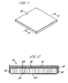
- FIGURE 1 is a perspective view of a composite panel in accordance with the present invention;
- FIGURE 2 is a cross-section of the panel of Figure 1 of along the line of A-A;
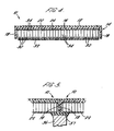
- FIGURE 3 is a schematic diagram showing the initial steps in manufacture of the panel of Figures 1 and 2;
- FIGURE 4 is a cross-section similar to Figure 2 showing a panel incorporating an LED matrix; and
- FIGURE 5 shows how two adjacent panels may be supported as flooring.
-
- A
composite panel 10 in accordance with an embodiment of the present invention is in the form of a square tile having a large surface area and a comparatively small depth. A typical tile is approximately 0.5m along each side and approximately 3cm thick. However, a rectangular tile or other shape which can be conveniently tessellated may also be produced. - As best seen in Figure 2, the panel has an
upper surface 12 which is at least partly transparent or translucent and may be coloured as described further below. Theupper surface 12 is preferably formed of epoxy resin or polyester resin. This provides a hardwearing layer which is suitable as a floor surface and can be walked upon. - Beneath the
upper surface 12 is an inverted tray-shaped structure 14 of composite material, such as glass fibre reinforced plastic. Thistray 14 has atop surface 16 and fourside walls 18. - Within the cavity defined by the
composite tray 14 is a block ofhoneycomb material 20. Thehoneycomb material 20 is secured to the underside of thetop surface 16 of thecomposite tray 14 byadhesive resin 24. Thehoneycomb material 20 is spaced inwardly from thecomposite side walls 18 for the reasons discussed below. Thehoneycomb material 20 is provided with abacking sheet 22 which may be of fibre reinforced plastic or other material as discussed below. Thehoneycomb material 20 andbacking sheet 22 are preferably dimensioned to protrude slightly out of the cavity defined by thecomposite tray 14. Thehoneycomb material 20 is preferably constructed from perforated aluminum, i.e aluminum sheet with a number of minute pores formed in the metal. - Although this is a preferred embodiment, a
tray 14 withside walls 18 is not essential. Thepanel 10 could consist of simply thetop surface 16, with thehoneycomb material 20 andbacking sheet 22 secured to one side and theupper resin surface 12 on the other. - The
panel 10 may be manufactured according to the following process partly illustrated in Figure 3. First, amould 26 having ashallow cavity 28 is provided, for example of Formica (RTM), with a degreaser lining the cavity. The base and sides of thecavity 28 are lined with fibre reinforced plastic to create thetray 14. This is typically done by hand and the fibre reinforced plastic is cured in a cold cure process. - If the
panel 10 is being manufactured without thesidewalls 18, then only the base of the cavity is lined to form thetop surface 16. - After curing of the fibre reinforced
plastic 14, thebase 16 is coated with anadhesive resin 24. A block ofhoneycomb material 20, typically with a conventional preformed fibre reinforcedplastic backing sheet 22, is placed in thecomposite tray 14, the open end of the honeycomb contacting theadhesive resin 24. Thehoneycomb block 20 is smaller than the inside dimensions of thetray 14 so that the edges of the honeycomb are spaced from the sides of the composite tray 14 (or from the sides of themould 26 if theside walls 18 are not present) all the way around. Theadhesive resin 24 is then cured, during which process heat is evolved. This heat causes air trapped in the cells of thehoneycomb material 20 between thebacking sheet 22 and theadhesive resin 24 to expand and it has been found that this expansion leads to blistering of the panel surface, which is of course unacceptable in use. This problem has been overcome by using perforated material, such as aluminum, to form thehoneycomb material 20, thereby allowing trapped air to escape from cell to cell and eventually out of thehoneycomb material 20 at the edges, where it is spaced from the side walls of the composite tray 14 (or simply the sides of the mould 26). - When the
honeycomb 20 has been securely bonded in place, thecomposite tray 14 is removed from themould 26. The gap between thehoneycomb material 20 and theside walls 18 of the composite tray may be covered with tape (not shown), such as structural composite tape, for convenience and to prevent dirt or debris entering the gap. - The
panel 10 is inverted so that thebase 16 of thecomposite tray 14 is uppermost. The upper surface is then coated with a layer of epoxy resin, or polyester resin, to provide the hardwearingupper surface 12. - As mentioned above, typically a
panel 10 produced by this process is approximately 0.5m along each side with a depth of approximately 3cm, the top coat of epoxy resin being about 0.5cm thick. A panel of these dimensions can be used as flooring. If it is supported on conventional pedestal supports 36 withresilient bearing pads 37 as shown in Figure 5 at approximately 0.5m spacing, the floor is able to withstand loads of 5kN/m2 and can cope with point loads, such as provided by high heeled shoes. When used in this way, theresilient bearing pads 37 of the pedestal supports 36 bear against thebacking layer 22 of thehoneycomb material 20 and not theside walls 18 of thecomposite tray 14, which would be vulnerable to delamination if exposed to high loads. Larger panels up to approximately 1mx3m can however conveniently be made by the same process. -
Panels 10 can also be used, singly or grouped together as decorative panels hung on an existing wall or to themselves create a partition wall. - The
upper layer 12 of epoxy resin, thecomposite tray 14 and thebacking material 22 may all be made of transparent or translucent material so that light is able to pass through thepanel 10. The honeycomb structure is then visible which in itself provides an interesting visual effect. However, further effects can be achieved by colouring and/or lighting thepanel 10 as described below. - In order to colour the
panel 10, the mould may be sprayed with a coloured or tinted resin before thecomposite tray 14 is layed within the mould. Sections of the mould may be masked off and sprayed with further colours to provide interesting visual effects. - Further interest can be provided by lighting the panel in various ways. Firstly, the panel may be backlit in a conventional manner in which light is shone through the
panel 10 from the direction of thebacking sheet 22 towards the upper (or front)surface 12. However, back lighting requires a certain amount of space to be provided behind thepanel 10 to accommodate the back lighting apparatus and therefore the system is not suited to providing simple partition walls between adjacent spaces or in situations where space is limited for any other reason. - A second embodiment of lit panel employs a layer of electroluminescent film behind the block of
honeycomb material 20. This consists of a double film metallic sheet which glows when a high frequency current is passed through it. The electroluminescent film may be used as thebacking sheet 22 of thehoneycomb 20, or may be placed behind the backing sheet, i.e. on the side remote from thehoneycomb material 20. Incorporating the electroluminescent film into thepanel 10 provides a glowing panel which is useful where light without depth is desired as a visual effect. - In a third embodiment, a more complex lighting system is provided which allows more complicated visuals to be displayed. In this embodiment, a matrix of
illumination devices 30 is provided on a printed circuit board (PCB)32. Thedevices 30 are conveniently LED's although any other type of lighting device could also be used. The LED's may be soldered to the PCB in a conventional manner or may be the more compact surface mounted type. The matrix is arranged so that eachLED 30 sits in acell 34 of thehoneycomb material 20. An LED may be situated in everycell 34, or only some cells. When lit, eachLED 30 floodlights itsparticular cell 34 due to internal reflection from the metallic walls. Since thecells 34 of thehoneycomb material 20 are hexagonal, this effect provides a hexagonal pixel when viewed through thetop surface 12 and the matrix of hexagonal pixels provided by thepanel 10 can be used to display curves and represent pictures. Since the pixel size is relatively large and the resolution is low as compared with, say a TV, hexagonal pixels in fact make it easier to generate curves, and hence relatively complex graphics and pictures, than an equivalent size square pixel matrix. Typically, the size of onecell 34 in the honeycomb structure is in the range of 0.6cm to 2.5cm across, with a cell size of 1.3cm to 2.5cm being preferred. - The PCB 32 on which the LED's 30 are mounted can be used as the
backing sheet 22 for thehoneycomb material 20. A further layer of composite (not shown) may be provided across the back of the PCB 32 for added structural strength. Additionally, whilst it is simple to provide PCB's of approximately 0.5m x 0.5m for use with a panel of equivalent size, if it is desired to manufacture a larger panel a number of separate PCB's may be used to make up the required area. - The LED's used may provide a single colour, typically red, to provide a monochrome display. Alternatively, the LED matrix may be made up of three different colours of LED, with only one colour being in one
cell 34. Alternatively, tricolour LED's, which are single LED's able to display three different colours, may be used. With either of these latter two arrangements it is possible to provide a full colour display on thepanel 10. - For additional visual effects, a symbol or logo may be added, for example, by transfer or screen printing to the
upper surface 12 or on thebacking layer 22 so that the symbol is illuminated or silhouetted when thepanel 10 is used with a lighting device. - The
panel 10 may also be provided with a back layer (not shown) of epoxy resin, polyester, or a mixture of the two, which seals the back of thepanel 10, allowing it to be used in outdoor environments. - It will be apparent to those skilled in the art that the present invention provides an improved composite panel which is simple to manufacture, lightweight but very hardwearing in use and allows lighting devices to be incorporated in it to produce visual effects with varying degrees of sophistication. It will also be appreciated that variations and modifications can be made to the precise configuration described in the materials used without departing from the scope of the present invention.
Claims (27)
- A composite panel comprising a layer of fibre reinforced plastic (FRP) material, a block of honeycomb material, formed of perforated sheet, having one side secured to one side of the FRP layer, a backing layer attached to the other side of the honeycomb material and a resin coating on the other side of the FRP layer, wherein the fibre reinforced plastic material and the resin coating are at least partly transparent or translucent.
- A composite panel as claimed in claim 1, wherein the FRP layer forms the base of a tray-shaped structure which further comprises side walls formed of FRP material and depending from the FRP layer so as to define a cavity within which the honeycomb material is located.
- A composite panel as claimed in claim 2, wherein the honeycomb material is spaced from the side walls of the tray-shaped structure.
- A composite panel as claimed in claim 3, wherein the spacing between the honeycomb material and the side walls of the tray is covered by fibre reinforced tape.
- A composite panel as claimed in any preceding claim, wherein the honeycomb material is formed from aluminum.
- A composite panel as claimed in any preceding claim, wherein the resin coating is an epoxy resin or polyester resin.
- A composite panel as claimed in any preceding claim, wherein one or more colours or tints are applied to the fibre reinforced plastic material.
- A composite panel as claimed in any preceding claim, wherein the backing layer attached to the honeycomb material is fibre reinforced plastic.
- A composite panel as claimed in any of claims 1-7, wherein the backing layer attached to the honeycomb comprises electroluminescent film.
- A composite panel as claimed in any of claims 1-6, wherein an illumination device is provided in each of a plurality of the cells of the honeycomb layer.
- A composite panel as claimed in claim 10, wherein the illumination devices are secured to the backing material.
- A composite panel as claimed in claim 10 or claim 11, wherein all the illumination devices produce light of the same colour.
- A composite panel as claimed in claim 10 or claim 11, wherein illumination devices of three different colours are provided.
- A composite panel as claimed in claim 10 or claim 11, wherein each illumination device is able to produce light of three colours.
- A composite panel as claimed in any of claims 10 to 14, wherein the illumination devices comprise LEDs.
- A composite panel as claimed in claim 2 or claim 3, wherein the honeycomb material and/or the backing material protrude out of the cavity.
- A composite panel as claimed in claim 2 or claim 3, further comprising a sealing layer formed on the side of the backing layer remote from the honeycomb material to seal the cavity.
- A floor comprising a plurality of composite panels as claimed in any preceding claim.
- A floor as claimed in claim 18, wherein the plurality of composite panels are supported on pedestal supports with resilient bearing pads which bear against the backing layer and do not bear against the side walls of the tray-shaped structure (if present).
- A wall comprising a plurality of composite panels as claimed in any of claims 1 to 17.
- A method of forming a composite panel comprising the steps of:
providing a mould with a mould cavity, lining the base of the cavity with fibre reinforced plastic (FRP) material to form an FRP layer, cold curing the fibre reinforced plastic material, covering the FRP layer with adhesive, securing honeycomb material produced from perforated sheet to the FRP layer with the adhesive, the honeycomb material having a backing layer, removing the FRP layer with attached the honeycomb material from the mould cavity, inverting the FRP layer and applying a resin coating to the other side of the FRP layer, wherein the fibre reinforced plastic material and the resin coating are at least partially transparent or translucent. - A method as claimed in claim 21, further comprising the step of lining the sides of the mould cavity with FRP material to form a tray-shaped structure with a base and side walls.
- A method as claimed in any of claim 21 or claim 22, further comprising the step of applying one or more colours or tints to the mould before lining the cavity with fibre reinforced plastic.
- A method as claimed in any of claims 21 to 23, wherein the backing sheet consists of fibre reinforced plastic.
- A method as claimed in any of claims 21 to 23, wherein the backing sheet consists of electroluminescent film.
- A method as claimed in any of claims 21 to 25, further comprising the step of providing an illumination device in each of a plurality of the cells in the honeycomb material.
- A method as claimed in any of claims 21 to 26, further comprising the step of applying a sealing layer to the backing material to seal the panel.
Applications Claiming Priority (2)
| Application Number | Priority Date | Filing Date | Title |
|---|---|---|---|
| GB9907422 | 1999-03-31 | ||
| GB9907422A GB2348442B (en) | 1999-03-31 | 1999-03-31 | Composite panel and method of manufacture |
Publications (3)
| Publication Number | Publication Date |
|---|---|
| EP1041211A2 true EP1041211A2 (en) | 2000-10-04 |
| EP1041211A3 EP1041211A3 (en) | 2003-02-26 |
| EP1041211B1 EP1041211B1 (en) | 2007-02-21 |
Family
ID=10850719
Family Applications (1)
| Application Number | Title | Priority Date | Filing Date |
|---|---|---|---|
| EP00302705A Expired - Lifetime EP1041211B1 (en) | 1999-03-31 | 2000-03-30 | Composite panel and method of manufacture |
Country Status (7)
| Country | Link |
|---|---|
| US (1) | US6667089B1 (en) |
| EP (1) | EP1041211B1 (en) |
| AT (1) | ATE354705T1 (en) |
| DE (1) | DE60033460T2 (en) |
| DK (1) | DK1041211T3 (en) |
| ES (1) | ES2282078T3 (en) |
| GB (1) | GB2348442B (en) |
Cited By (11)
| Publication number | Priority date | Publication date | Assignee | Title |
|---|---|---|---|---|
| EP1933086A1 (en) | 2006-12-15 | 2008-06-18 | Bartenbach Christian | Building component with at least one illuminant |
| EP2082864A1 (en) * | 2008-01-28 | 2009-07-29 | Grupo Antolin Ingenieria, S.A. | Method for manufacturing reinforced panels for the inner liner of vehicles and panel obtained by means of said method |
| EP2154427A1 (en) * | 2008-08-15 | 2010-02-17 | Lighting Science Group Corporation | Heat dissipating LED light panel made of sustainable material |
| WO2014019674A1 (en) * | 2012-07-30 | 2014-02-06 | Lufthansa Technik Ag | Built-in optical component for the interior fittings of an aircraft and correspondingly fitted aircraft |
| WO2016030128A1 (en) * | 2014-08-29 | 2016-03-03 | Philips Lighting Holding B.V. | Lighting module and housing |
| WO2016097950A1 (en) * | 2014-12-19 | 2016-06-23 | Conf Industries S.R.L. | Modular panel for hospital environments |
| ITUB20155799A1 (en) * | 2015-11-20 | 2017-05-20 | Edilanzutti S R L | COVERING PANEL AND CORRESPONDENT METHOD OF INSTALLATION |
| EP3444181A1 (en) * | 2017-08-17 | 2019-02-20 | The Boeing Company | Vehicle luminous composite floor panel |
| EP3552964A1 (en) * | 2018-04-10 | 2019-10-16 | Rockwell Collins, Inc. | Integrated micro-led luminous aircraft panel |
| US10556706B2 (en) | 2018-04-10 | 2020-02-11 | B/E Aerospace, Inc. | Integrated aircraft signage, lighting, and display system |
| DE102018121194A1 (en) * | 2018-08-30 | 2020-03-05 | Airbus Operations Gmbh | Interior lighting, trim element, aircraft with interior lighting and method for producing interior lighting |
Families Citing this family (25)
| Publication number | Priority date | Publication date | Assignee | Title |
|---|---|---|---|---|
| TW468283B (en) | 1999-10-12 | 2001-12-11 | Semiconductor Energy Lab | EL display device and a method of manufacturing the same |
| US8070994B2 (en) | 2004-06-18 | 2011-12-06 | Zephyros, Inc. | Panel structure |
| US7614199B2 (en) * | 2004-11-18 | 2009-11-10 | Smalley Iii Arthur L | Method and system for modular building construction |
| US20080037287A1 (en) * | 2006-08-14 | 2008-02-14 | Robert Michael Krohn | Backlight panel and manufacturing method thereof |
| US20100025147A1 (en) * | 2005-10-31 | 2010-02-04 | L&L Products, Inc. | Damping material, method of forming the damping material and method of using the damping material |
| US7695172B2 (en) * | 2006-06-30 | 2010-04-13 | The Boeing Company | Thermally conductive panel |
| US20100281910A1 (en) * | 2006-08-31 | 2010-11-11 | Koninklijke Philips Electronics N V | Door for a cold storage device such as a refrigerator or freezer |
| WO2008085161A1 (en) * | 2007-01-09 | 2008-07-17 | Lighting Panels, Llc | Backlight panel and manufacturing method thereof |
| WO2009138785A1 (en) * | 2008-05-16 | 2009-11-19 | Bae Systems Plc | Camouflage panel |
| US8210953B1 (en) | 2008-11-12 | 2012-07-03 | Whitewater Composites Ltd. | Translucent closed-molded fiber-reinforced plastic and method of making the same |
| WO2011036614A2 (en) * | 2009-09-24 | 2011-03-31 | Koninklijke Philips Electronics N.V. | Floor covering system comprising a lighting system |
| US8597455B1 (en) * | 2009-10-02 | 2013-12-03 | Metacomb, Inc. | Translucent building material comprising corrugated cardboard |
| US8156710B1 (en) * | 2010-11-19 | 2012-04-17 | Advance Vinyl Floor Manufacturing Corp. | Method and apparatus for floor tiles and planks |
| US8601757B2 (en) * | 2010-05-27 | 2013-12-10 | Solatube International, Inc. | Thermally insulating fenestration devices and methods |
| SE534994C2 (en) * | 2010-07-28 | 2012-03-06 | Anders Rensmo | light plate |
| KR101417410B1 (en) * | 2012-11-16 | 2014-07-08 | 현대자동차주식회사 | 3D-panel for implementing mood illumination applied real material |
| CN103015671A (en) * | 2013-01-18 | 2013-04-03 | 江苏美亚新型饰材有限公司 | Antistatic access floor |
| US8800245B1 (en) | 2013-03-27 | 2014-08-12 | Advancecd Vinyl Floor Manufacturing Corp. | Method and apparatus for floor tiles and planks |
| US9188733B2 (en) | 2013-06-07 | 2015-11-17 | Steelcase Inc. | Panel light assembly |
| CN103419417A (en) * | 2013-08-21 | 2013-12-04 | 上海惊叹化学有限公司 | Multilayer honeycomb board |
| CA2890770A1 (en) * | 2014-05-06 | 2015-11-06 | Emballages Cre-O-Pack Canada Inc. | Sandwich panel, container made of such a sandwich panel and method of manufacturing the same |
| CN104153539B (en) * | 2014-08-15 | 2015-09-09 | 广州鸿力复合材料有限公司 | A kind of Novel floor brick and manufacture method thereof |
| DE102014226529A1 (en) | 2014-12-19 | 2016-06-23 | Bayerische Motoren Werke Aktiengesellschaft | CFRP-reinforced semi-transparent flat component, and a method for its production |
| AU2016232714A1 (en) | 2015-03-18 | 2017-10-26 | Solatube International, Inc. | Daylight collectors with diffuse and direct light collection |
| US9816675B2 (en) | 2015-03-18 | 2017-11-14 | Solatube International, Inc. | Daylight collectors with diffuse and direct light collection |
Citations (3)
| Publication number | Priority date | Publication date | Assignee | Title |
|---|---|---|---|---|
| US2998342A (en) * | 1956-06-07 | 1961-08-29 | Englander Co Inc | Honeycomb panel |
| US3211253A (en) * | 1964-01-15 | 1965-10-12 | Douglas Aircraft Co Inc | Acoustical panel comprising a cellular core having a face thereof coated with fibers bridging the cells |
| GB2316651A (en) * | 1996-08-28 | 1998-03-04 | Nicholas Mcmahon | Structure comprising honeycomb core and outer skin |
Family Cites Families (5)
| Publication number | Priority date | Publication date | Assignee | Title |
|---|---|---|---|---|
| US4573304A (en) * | 1983-11-25 | 1986-03-04 | Donn Incorporated | Honeycomb floor panel and the like |
| US5106668A (en) * | 1989-06-07 | 1992-04-21 | Hexcel Corporation | Multi-layer honeycomb structure |
| US5888612A (en) * | 1995-06-05 | 1999-03-30 | Poly Plus Inc. | Load-bearing structures |
| DE29806139U1 (en) * | 1998-04-03 | 1999-08-05 | Staudenmayer Winfried | Component |
| US6348960B1 (en) * | 1998-11-06 | 2002-02-19 | Kimotot Co., Ltd. | Front scattering film |
-
1999
- 1999-03-31 GB GB9907422A patent/GB2348442B/en not_active Expired - Fee Related
-
2000
- 2000-03-30 ES ES00302705T patent/ES2282078T3/en not_active Expired - Lifetime
- 2000-03-30 US US09/538,778 patent/US6667089B1/en not_active Expired - Fee Related
- 2000-03-30 DK DK00302705T patent/DK1041211T3/en active
- 2000-03-30 EP EP00302705A patent/EP1041211B1/en not_active Expired - Lifetime
- 2000-03-30 DE DE60033460T patent/DE60033460T2/en not_active Expired - Fee Related
- 2000-03-30 AT AT00302705T patent/ATE354705T1/en not_active IP Right Cessation
Patent Citations (3)
| Publication number | Priority date | Publication date | Assignee | Title |
|---|---|---|---|---|
| US2998342A (en) * | 1956-06-07 | 1961-08-29 | Englander Co Inc | Honeycomb panel |
| US3211253A (en) * | 1964-01-15 | 1965-10-12 | Douglas Aircraft Co Inc | Acoustical panel comprising a cellular core having a face thereof coated with fibers bridging the cells |
| GB2316651A (en) * | 1996-08-28 | 1998-03-04 | Nicholas Mcmahon | Structure comprising honeycomb core and outer skin |
Cited By (16)
| Publication number | Priority date | Publication date | Assignee | Title |
|---|---|---|---|---|
| EP1933086A1 (en) | 2006-12-15 | 2008-06-18 | Bartenbach Christian | Building component with at least one illuminant |
| EP2082864A1 (en) * | 2008-01-28 | 2009-07-29 | Grupo Antolin Ingenieria, S.A. | Method for manufacturing reinforced panels for the inner liner of vehicles and panel obtained by means of said method |
| EP2154427A1 (en) * | 2008-08-15 | 2010-02-17 | Lighting Science Group Corporation | Heat dissipating LED light panel made of sustainable material |
| US7744252B2 (en) | 2008-08-15 | 2010-06-29 | Lighting Science Group Corporation | Sustainably constructed heat dissipating integrated lighting surface |
| WO2014019674A1 (en) * | 2012-07-30 | 2014-02-06 | Lufthansa Technik Ag | Built-in optical component for the interior fittings of an aircraft and correspondingly fitted aircraft |
| US10179539B2 (en) | 2012-07-30 | 2019-01-15 | Lufthansa Technik Ag | Built-in optical component for the interior fittings of an aircraft and correspondingly fitted aircraft |
| US9989220B2 (en) | 2014-08-29 | 2018-06-05 | Philips Lighting Holding B.V. | Lighting module and housing |
| WO2016030128A1 (en) * | 2014-08-29 | 2016-03-03 | Philips Lighting Holding B.V. | Lighting module and housing |
| WO2016097950A1 (en) * | 2014-12-19 | 2016-06-23 | Conf Industries S.R.L. | Modular panel for hospital environments |
| ITUB20155799A1 (en) * | 2015-11-20 | 2017-05-20 | Edilanzutti S R L | COVERING PANEL AND CORRESPONDENT METHOD OF INSTALLATION |
| EP3444181A1 (en) * | 2017-08-17 | 2019-02-20 | The Boeing Company | Vehicle luminous composite floor panel |
| US10562605B2 (en) | 2017-08-17 | 2020-02-18 | The Boeing Company | Vehicle luminous composite floor panel |
| EP3552964A1 (en) * | 2018-04-10 | 2019-10-16 | Rockwell Collins, Inc. | Integrated micro-led luminous aircraft panel |
| US10556706B2 (en) | 2018-04-10 | 2020-02-11 | B/E Aerospace, Inc. | Integrated aircraft signage, lighting, and display system |
| US10864997B2 (en) | 2018-04-10 | 2020-12-15 | Rockwell Collins, Inc. | Integrated micro-LED luminous aircraft panel |
| DE102018121194A1 (en) * | 2018-08-30 | 2020-03-05 | Airbus Operations Gmbh | Interior lighting, trim element, aircraft with interior lighting and method for producing interior lighting |
Also Published As
| Publication number | Publication date |
|---|---|
| GB2348442B (en) | 2001-08-22 |
| US6667089B1 (en) | 2003-12-23 |
| GB2348442A (en) | 2000-10-04 |
| GB9907422D0 (en) | 1999-05-26 |
| DK1041211T3 (en) | 2007-07-02 |
| ATE354705T1 (en) | 2007-03-15 |
| DE60033460D1 (en) | 2007-04-05 |
| ES2282078T3 (en) | 2007-10-16 |
| DE60033460T2 (en) | 2007-10-31 |
| EP1041211A3 (en) | 2003-02-26 |
| EP1041211B1 (en) | 2007-02-21 |
Similar Documents
| Publication | Publication Date | Title |
|---|---|---|
| EP1041211B1 (en) | Composite panel and method of manufacture | |
| CN101743488B (en) | Optical elements with internal optical features and methods of fabricating same | |
| JP5138849B2 (en) | Substantially flat film structure | |
| US20090190353A1 (en) | Modular display system | |
| KR100597977B1 (en) | Sign faces having reflective films and methods of using same | |
| EP3416831B1 (en) | A decorative panel | |
| JP6342424B2 (en) | Glazing units and assemblies | |
| JP2004530932A (en) | Composite display board | |
| CN101208939A (en) | Multiple reflection panel | |
| CN110136595A (en) | A kind of display panel and preparation method thereof, display device | |
| BRPI0616876A2 (en) | trajectory marker | |
| KR200445811Y1 (en) | Plate lighting plate with Led module for display device | |
| WO2000012844A1 (en) | Illuminated image memorial | |
| US10841552B2 (en) | Chroma keying illumination system | |
| WO2003026904A3 (en) | Changing appearance glass tile | |
| JP2002244596A (en) | Assembled transparent body internally having bright drawing section | |
| CN220105326U (en) | Optical film and display panel | |
| CN101882404B (en) | Compass array display device | |
| GB2382053A (en) | Surface with profiled ridges to produce variable visual effects | |
| JP2006113324A (en) | Lighting fixture | |
| US20080022626A1 (en) | Floor Covering Having Two Distinct Representations | |
| CN210002743U (en) | base plate for decorative material and decorative composite plate | |
| TW477746B (en) | Method for forming transparent advertisement sticker and its product | |
| WO2000001523A1 (en) | Structural urethane panel | |
| AU747513B2 (en) | Illuminated image memorial |
Legal Events
| Date | Code | Title | Description |
|---|---|---|---|
| PUAI | Public reference made under article 153(3) epc to a published international application that has entered the european phase |
Free format text: ORIGINAL CODE: 0009012 |
|
| AK | Designated contracting states |
Kind code of ref document: A2 Designated state(s): AT BE CH CY DE DK ES FI FR GB GR IE IT LI LU MC NL PT SE |
|
| AX | Request for extension of the european patent |
Free format text: AL;LT;LV;MK;RO;SI |
|
| 17P | Request for examination filed |
Effective date: 20000925 |
|
| PUAL | Search report despatched |
Free format text: ORIGINAL CODE: 0009013 |
|
| AK | Designated contracting states |
Kind code of ref document: A3 Designated state(s): AT BE CH CY DE DK ES FI FR GB GR IE IT LI LU MC NL PT SE |
|
| AX | Request for extension of the european patent |
Extension state: AL LT LV MK RO SI |
|
| RIC1 | Information provided on ipc code assigned before grant |
Ipc: 7B 32B 3/12 B Ipc: 7E 04C 2/36 A Ipc: 7E 04F 13/18 B Ipc: 7E 04F 15/10 B |
|
| RAP1 | Party data changed (applicant data changed or rights of an application transferred) |
Owner name: B CONSULTANTS LIMITED |
|
| AKX | Designation fees paid |
Designated state(s): AT BE CH CY DE DK ES FI FR GB GR IE IT LI LU MC NL PT SE |
|
| RAP1 | Party data changed (applicant data changed or rights of an application transferred) |
Owner name: BOX CONSULTANTS LIMITED |
|
| RAP1 | Party data changed (applicant data changed or rights of an application transferred) |
Owner name: SMARTSLAB LIMITED |
|
| GRAP | Despatch of communication of intention to grant a patent |
Free format text: ORIGINAL CODE: EPIDOSNIGR1 |
|
| GRAS | Grant fee paid |
Free format text: ORIGINAL CODE: EPIDOSNIGR3 |
|
| RAP1 | Party data changed (applicant data changed or rights of an application transferred) |
Owner name: SMARTSLAB LIMITED |
|
| GRAA | (expected) grant |
Free format text: ORIGINAL CODE: 0009210 |
|
| AK | Designated contracting states |
Kind code of ref document: B1 Designated state(s): AT BE CH CY DE DK ES FI FR GB GR IE IT LI LU MC NL PT SE |
|
| PG25 | Lapsed in a contracting state [announced via postgrant information from national office to epo] |
Ref country code: LI Free format text: LAPSE BECAUSE OF FAILURE TO SUBMIT A TRANSLATION OF THE DESCRIPTION OR TO PAY THE FEE WITHIN THE PRESCRIBED TIME-LIMIT Effective date: 20070221 Ref country code: CH Free format text: LAPSE BECAUSE OF FAILURE TO SUBMIT A TRANSLATION OF THE DESCRIPTION OR TO PAY THE FEE WITHIN THE PRESCRIBED TIME-LIMIT Effective date: 20070221 Ref country code: FI Free format text: LAPSE BECAUSE OF FAILURE TO SUBMIT A TRANSLATION OF THE DESCRIPTION OR TO PAY THE FEE WITHIN THE PRESCRIBED TIME-LIMIT Effective date: 20070221 |
|
| REG | Reference to a national code |
Ref country code: GB Ref legal event code: FG4D |
|
| REG | Reference to a national code |
Ref country code: CH Ref legal event code: EP |
|
| REF | Corresponds to: |
Ref document number: 60033460 Country of ref document: DE Date of ref document: 20070405 Kind code of ref document: P |
|
| REG | Reference to a national code |
Ref country code: IE Ref legal event code: FG4D |
|
| PG25 | Lapsed in a contracting state [announced via postgrant information from national office to epo] |
Ref country code: SE Free format text: LAPSE BECAUSE OF FAILURE TO SUBMIT A TRANSLATION OF THE DESCRIPTION OR TO PAY THE FEE WITHIN THE PRESCRIBED TIME-LIMIT Effective date: 20070521 |
|
| REG | Reference to a national code |
Ref country code: DK Ref legal event code: T3 |
|
| PG25 | Lapsed in a contracting state [announced via postgrant information from national office to epo] |
Ref country code: PT Free format text: LAPSE BECAUSE OF FAILURE TO SUBMIT A TRANSLATION OF THE DESCRIPTION OR TO PAY THE FEE WITHIN THE PRESCRIBED TIME-LIMIT Effective date: 20070723 |
|
| ET | Fr: translation filed | ||
| REG | Reference to a national code |
Ref country code: CH Ref legal event code: PL |
|
| REG | Reference to a national code |
Ref country code: ES Ref legal event code: FG2A Ref document number: 2282078 Country of ref document: ES Kind code of ref document: T3 |
|
| PLBE | No opposition filed within time limit |
Free format text: ORIGINAL CODE: 0009261 |
|
| STAA | Information on the status of an ep patent application or granted ep patent |
Free format text: STATUS: NO OPPOSITION FILED WITHIN TIME LIMIT |
|
| 26N | No opposition filed |
Effective date: 20071122 |
|
| PG25 | Lapsed in a contracting state [announced via postgrant information from national office to epo] |
Ref country code: IE Free format text: LAPSE BECAUSE OF NON-PAYMENT OF DUE FEES Effective date: 20070330 Ref country code: MC Free format text: LAPSE BECAUSE OF NON-PAYMENT OF DUE FEES Effective date: 20070331 |
|
| PG25 | Lapsed in a contracting state [announced via postgrant information from national office to epo] |
Ref country code: GR Free format text: LAPSE BECAUSE OF FAILURE TO SUBMIT A TRANSLATION OF THE DESCRIPTION OR TO PAY THE FEE WITHIN THE PRESCRIBED TIME-LIMIT Effective date: 20070522 |
|
| PGFP | Annual fee paid to national office [announced via postgrant information from national office to epo] |
Ref country code: ES Payment date: 20080328 Year of fee payment: 9 Ref country code: DK Payment date: 20080311 Year of fee payment: 9 |
|
| PGFP | Annual fee paid to national office [announced via postgrant information from national office to epo] |
Ref country code: GB Payment date: 20080325 Year of fee payment: 9 Ref country code: IT Payment date: 20080308 Year of fee payment: 9 Ref country code: NL Payment date: 20080327 Year of fee payment: 9 |
|
| PGFP | Annual fee paid to national office [announced via postgrant information from national office to epo] |
Ref country code: AT Payment date: 20080325 Year of fee payment: 9 |
|
| PGFP | Annual fee paid to national office [announced via postgrant information from national office to epo] |
Ref country code: DE Payment date: 20080314 Year of fee payment: 9 Ref country code: FR Payment date: 20080311 Year of fee payment: 9 |
|
| PGFP | Annual fee paid to national office [announced via postgrant information from national office to epo] |
Ref country code: BE Payment date: 20080411 Year of fee payment: 9 |
|
| PG25 | Lapsed in a contracting state [announced via postgrant information from national office to epo] |
Ref country code: CY Free format text: LAPSE BECAUSE OF FAILURE TO SUBMIT A TRANSLATION OF THE DESCRIPTION OR TO PAY THE FEE WITHIN THE PRESCRIBED TIME-LIMIT Effective date: 20070221 |
|
| PG25 | Lapsed in a contracting state [announced via postgrant information from national office to epo] |
Ref country code: LU Free format text: LAPSE BECAUSE OF NON-PAYMENT OF DUE FEES Effective date: 20070330 |
|
| BERE | Be: lapsed |
Owner name: SMARTSLAB LTD Effective date: 20090331 |
|
| PG25 | Lapsed in a contracting state [announced via postgrant information from national office to epo] |
Ref country code: AT Free format text: LAPSE BECAUSE OF NON-PAYMENT OF DUE FEES Effective date: 20090330 |
|
| REG | Reference to a national code |
Ref country code: DK Ref legal event code: EBP |
|
| GBPC | Gb: european patent ceased through non-payment of renewal fee |
Effective date: 20090330 |
|
| NLV4 | Nl: lapsed or anulled due to non-payment of the annual fee |
Effective date: 20091001 |
|
| REG | Reference to a national code |
Ref country code: FR Ref legal event code: ST Effective date: 20091130 |
|
| PG25 | Lapsed in a contracting state [announced via postgrant information from national office to epo] |
Ref country code: DE Free format text: LAPSE BECAUSE OF NON-PAYMENT OF DUE FEES Effective date: 20091001 |
|
| PG25 | Lapsed in a contracting state [announced via postgrant information from national office to epo] |
Ref country code: BE Free format text: LAPSE BECAUSE OF NON-PAYMENT OF DUE FEES Effective date: 20090331 Ref country code: NL Free format text: LAPSE BECAUSE OF NON-PAYMENT OF DUE FEES Effective date: 20091001 |
|
| PG25 | Lapsed in a contracting state [announced via postgrant information from national office to epo] |
Ref country code: DK Free format text: LAPSE BECAUSE OF NON-PAYMENT OF DUE FEES Effective date: 20090331 Ref country code: FR Free format text: LAPSE BECAUSE OF NON-PAYMENT OF DUE FEES Effective date: 20091123 Ref country code: GB Free format text: LAPSE BECAUSE OF NON-PAYMENT OF DUE FEES Effective date: 20090330 |
|
| REG | Reference to a national code |
Ref country code: ES Ref legal event code: FD2A Effective date: 20090331 |
|
| PG25 | Lapsed in a contracting state [announced via postgrant information from national office to epo] |
Ref country code: ES Free format text: LAPSE BECAUSE OF NON-PAYMENT OF DUE FEES Effective date: 20090331 |
|
| PG25 | Lapsed in a contracting state [announced via postgrant information from national office to epo] |
Ref country code: IT Free format text: LAPSE BECAUSE OF NON-PAYMENT OF DUE FEES Effective date: 20090330 |