EP1041417A2 - Fiber optic connector sleeve - Google Patents
Fiber optic connector sleeve Download PDFInfo
- Publication number
- EP1041417A2 EP1041417A2 EP00302718A EP00302718A EP1041417A2 EP 1041417 A2 EP1041417 A2 EP 1041417A2 EP 00302718 A EP00302718 A EP 00302718A EP 00302718 A EP00302718 A EP 00302718A EP 1041417 A2 EP1041417 A2 EP 1041417A2
- Authority
- EP
- European Patent Office
- Prior art keywords
- fiber optic
- sleeve
- optic connector
- connector sleeve
- connector
- Prior art date
- Legal status (The legal status is an assumption and is not a legal conclusion. Google has not performed a legal analysis and makes no representation as to the accuracy of the status listed.)
- Withdrawn
Links
- 239000000835 fiber Substances 0.000 title claims abstract description 65
- 238000003780 insertion Methods 0.000 claims description 3
- 230000037431 insertion Effects 0.000 claims description 3
- 239000013307 optical fiber Substances 0.000 description 5
- 238000009434 installation Methods 0.000 description 3
- 238000009420 retrofitting Methods 0.000 description 2
- 230000013011 mating Effects 0.000 description 1
- 238000000034 method Methods 0.000 description 1
- 238000012986 modification Methods 0.000 description 1
- 230000004048 modification Effects 0.000 description 1
- 230000003287 optical effect Effects 0.000 description 1
- 230000000135 prohibitive effect Effects 0.000 description 1
Images


Classifications
-
- G—PHYSICS
- G02—OPTICS
- G02B—OPTICAL ELEMENTS, SYSTEMS OR APPARATUS
- G02B6/00—Light guides; Structural details of arrangements comprising light guides and other optical elements, e.g. couplings
- G02B6/24—Coupling light guides
- G02B6/36—Mechanical coupling means
- G02B6/38—Mechanical coupling means having fibre to fibre mating means
- G02B6/3807—Dismountable connectors, i.e. comprising plugs
- G02B6/381—Dismountable connectors, i.e. comprising plugs of the ferrule type, e.g. fibre ends embedded in ferrules, connecting a pair of fibres
- G02B6/3826—Dismountable connectors, i.e. comprising plugs of the ferrule type, e.g. fibre ends embedded in ferrules, connecting a pair of fibres characterised by form or shape
- G02B6/3831—Dismountable connectors, i.e. comprising plugs of the ferrule type, e.g. fibre ends embedded in ferrules, connecting a pair of fibres characterised by form or shape comprising a keying element on the plug or adapter, e.g. to forbid wrong connection
-
- G—PHYSICS
- G02—OPTICS
- G02B—OPTICAL ELEMENTS, SYSTEMS OR APPARATUS
- G02B6/00—Light guides; Structural details of arrangements comprising light guides and other optical elements, e.g. couplings
- G02B6/24—Coupling light guides
- G02B6/36—Mechanical coupling means
- G02B6/38—Mechanical coupling means having fibre to fibre mating means
- G02B6/3807—Dismountable connectors, i.e. comprising plugs
- G02B6/3873—Connectors using guide surfaces for aligning ferrule ends, e.g. tubes, sleeves, V-grooves, rods, pins, balls
- G02B6/3885—Multicore or multichannel optical connectors, i.e. one single ferrule containing more than one fibre, e.g. ribbon type
-
- G—PHYSICS
- G02—OPTICS
- G02B—OPTICAL ELEMENTS, SYSTEMS OR APPARATUS
- G02B6/00—Light guides; Structural details of arrangements comprising light guides and other optical elements, e.g. couplings
- G02B6/24—Coupling light guides
- G02B6/36—Mechanical coupling means
- G02B6/38—Mechanical coupling means having fibre to fibre mating means
- G02B6/3807—Dismountable connectors, i.e. comprising plugs
- G02B6/389—Dismountable connectors, i.e. comprising plugs characterised by the method of fastening connecting plugs and sockets, e.g. screw- or nut-lock, snap-in, bayonet type
- G02B6/3893—Push-pull type, e.g. snap-in, push-on
-
- G—PHYSICS
- G02—OPTICS
- G02B—OPTICAL ELEMENTS, SYSTEMS OR APPARATUS
- G02B6/00—Light guides; Structural details of arrangements comprising light guides and other optical elements, e.g. couplings
- G02B6/24—Coupling light guides
- G02B6/36—Mechanical coupling means
- G02B6/38—Mechanical coupling means having fibre to fibre mating means
- G02B6/3807—Dismountable connectors, i.e. comprising plugs
- G02B6/3897—Connectors fixed to housings, casing, frames or circuit boards
Abstract

Description
- The present invention relates generally to fiber optic connector sleeves and, more particularly, to fiber optic connector sleeves capable of retrofitting a connector housing with panels outfitted for single fiber connectors and connector sleeves with multifiber connectors and connector sleeves.
- Fiber optic connector sleeves are frequently utilized to facilitate the mating of one or more fiber optic connectors. In this regard, a pair of fiber optic connectors can be inserted into the opposed ends of a fiber optic connector sleeve. The fiber optic connector sleeve serves to align the fiber optic connectors to a degree such that the optical fibers upon which the fiber optic connectors are mounted are appropriately aligned. As such, fiber optic connector sleeves can be mounted in a patch panel, within an enclosure, or the like so as to align a pair of fiber optic connectors inserted into opposite ends of the fiber optic connector sleeve. An example of such a connector sleeve is illustrated in U.S. Patent No. 5,359,688, assigned to the same assignee as the present invention ("the '688 Patent"). The connector sleeve disclosed therein is used with to SC connector, a connector mounted on a single optical fiber. Other connectors and connector sleeves are also known. Some of these include connectors that have multiple fibers mounted in each connector, such as the MT and the MTP connectors.
- With the use of optical fibers increasing at a rapid rate, many users need to increase the number of optical fibers at any given installation. However, those that first installed connectors and connector sleeve that have a single optical fiber, are finding that the multifiber connectors and sleeves do not properly fit into their equipment, such as patch panels. They are then faced with replacing their equipment or attempting to retrofit it. Replacing the equipment may be cost prohibitive. However, retrofitting the single fiber installations with available multifiber connectors may not provide the best solution, and is time consuming and expensive.
- Thus, a connector sleeve that allows for multifiber connectors to be installed in the same equipment that previously held a single fiber connector is needed. The present connector allows for a simple, cost-effective retrofit, allowing a single fiber application to be upgraded to a multifiber installation.
- To achieve these and other advantages, and in accordance with the purpose of the invention as embodied and broadly described herein, the present invention is directed to a fiber optic connector sleeve comprising a sleeve housing having a plurality of interior walls, the interior walls defining a lengthwise extending passageway through the sleeve housing for receiving at least a portion of a fiber optic connector. The sleeve housing comprises a plurality of positioning ribs extending lengthwise through the passageway for engaging the fiber optic connectors and for positioning the connectors in the sleeve, an alignment projection on at least one of the plurality of interior walls and extending lengthwise along a central portion of the passageway for positioning the connectors in the sleeve and a recess in one of the plurality of interior walls for engaging a latch on each connector, and a retaining clip mounted on the connector sleeve to hold the sleeve in an SC-type connector panel.
- Additional features and advantages of the invention will be set forth in the description which follows, and, in part, will be apparent from the description, or may be learned by practice of the invention. The objectives and other advantages of the invention will be realized and attained by the assembly particularly pointed out in the written description and claims hereof, as well as the appended drawings.
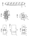
- The invention is illustrated by way of example in the drawings, in which:
- Figure 1 is a cross-sectional view of a prior art connector sleeve;
- Figure 2 is a perspective view of a connector sleeve constructed in accordance with the invention;
- Figure 3 is a perspective view of an SC adapter panel used with the connector sleeve of the present invention;
- Figure 4 is a front elevational view of the connector sleeve of Figure 2;
- Figure 5 is a top view of the connector sleeve of Figure 2;
- Figure 6 is a bottom view of the connector sleeve of Figure 2;
- Figure 7 is a side elevational view of the connector sleeve of Figure 2, and
- Figure 8 is a cross-sectional view of the connector sleeve of Figure 5 along the line 8--8; and
- Figure 9 is a perspective view of an alternative embodiment of a multifiber connector sleeve used to retrofit a single fiber connector panel.
-
- Figure 1 is a cross-section a known connector sleeve, an SC connector sleeve 10. Typically, the SC connector had only one fiber secured in the ferrule. The connector sleeve 10 was pushed into an adapter panel (see Figure 3) with an aperture that was closely sized to the outer dimensions of the sleeve. The sleeve 10 has a
clip 12 that slides over the sleeve 10 and engages two sides of the aperture to hold the sleeve 10 within the aperture. - The connector sleeves that hold the multifiber ferrules (e.g., MTP, MT RJ. etc.) are typically of a different size than the SC connector sleeve, they are typically smaller. Additionally, the multifiber connector sleeves are also designed to be held in the apertures of the panel with screws or other fasteners, rather than with a clip as with the SC. As a result, these multifiber connector sleeves cannot simply be inserted into the old panels that held the SC connector sleeves without modification to either the connector sleeve or the panel/aperture itself.
- The present invention, illustrated in a perspective view in Figure 2, is a
connector sleeve 20 that holds a multifiber connector and fits into the SC connector sleeve apertures. A standard adapter panel 22 withapertures 23 is shown in Figure 3. Theconnector sleeve 20 eliminates the need to replace the adapter panels 22 or to drill holes in the adapter panels for screws that are not present on the standard adapter panel 22. The exterior features ofconnector sleeve 20 are further shown in Figures 4-7.Connector sleeve 20 is preferably a unitary (monolithic) connector sleeve that can be molded in one piece, unlike some of the previous SC connector sleeves (see, e.g., the '688 patent).Connector sleeve 20 has anouter surface 24 that is generally rectangular (and corresponds to the SC connector sleeve). Theconnector sleeve 20 may also have at least oneflange 25 on theouter surface 24, but two are preferable in that they prevent the sleeve from being inserted too far into theaperture 23 on the adapter panel 22 and, being arranged on a shorter side of theconnector sleeve 20, allow for maximum spacing in the panel. Theflanges 25 also have an opening 25a that allows for other methods of securing thesleeve 20 to the panels 22. - The
connector sleeve 20 hasinner walls comers 34 and fore apassageway 42 through thesleeve 20. Thepassageway 42 opens at opposing ends 44,46 ofsleeve 20. A multifiber connector (housing of the connector shown in Figure 2) is inserted into the passageway at first end 44 to engage a second multifiber connector inserted at second end 46 (not shown). While theconnector sleeve 20 is a mirror image about theflange 25, it may also be possible to have a different style connector or arrangement at each end (discusses more below). - The
connector sleeve 20 has twoopenings 48, one in each side of thesleeve 20, to receive a latch from the inserted connector. In the preferred embodiment, theopenings 48 open completely (i.e., a window) from the outside through to thepassageway 42. However, theopenings 48 could also be recesses oninner wall 26 of thesleeve 20 instead. One end of thesleeve 20 also has arecessed portion 50 in a portion of theouter surface 24 of thesleeve 20 for aretaining clip 52, which is used to secure theconnector sleeve 20 in theaperture 23 of the adapter panel 22 as it was in the SC sleeve 10. In the preferred embodiment, theretaining clip 52 is a c-shaped clip (see Figure 2) that fits flush into therecessed portion 50, to prevent thesleeve 20 from catching on the adapter panel 22. While therecessed portion 50 and retainingclip 52 are shown at only one end of thesleeve 20, thesleeve 20 could have a recessed portion at either or both ends 44,46, to allow maximum flexibility in inserting the sleeve into the adapter panels 22. Other types and shapes of retainingclip 52 could be used. For example, the retainingclip 52 may only have onetab 53, rather than the twotabs 53 shown in Figure 2. - Figures 4 and 8 best show the internal configuration of the sleeve, portions of which are described in a patent application (EP-99305636.5) assigned to the same assignee as the present invention, the contents of which are incorporated herein by reference. The
connector sleeve 20 has positioningribs 54 that extend from thecorners 34 alonginner walls 28 and into thepassageway 42. Thus, theinner walls 28 are recessed themselves from thepositioning ribs 54. However, thewall 32 does not have a stepped profile as doinner walls 28 due to therecessed portion 50. Thewall 32 is constant along its height and depth into thepassageway 42 because the wall would be too thin along the area coincident with therecessed portion 50 if a recessed portion similar toportions 28,30 were attempted. - The
ribs 54 generally extend lengthwise from the opposed ends 44,46 of the fiberoptic connector sleeve 20 to a medial portion 56 of the fiberoptic connector sleeve 20. Although thepositioning ribs 54 can extend lengthwise through the entire fiberoptic connector sleeve 20, thepositioning ribs 54 typically terminate or are interrupted in a medial portion 56 of the fiberoptic connector sleeve 20, which may include various other alignment features, such as thealignment projections 58 that are designed to engage corresponding castellations 66 defined by the forward end of the fiber optic connector housing 60. - The
positioning ribs 54 engage the fiber optic housing 60 and position the fiber optic connector within the fiberoptic connector sleeve 20. In particular, thepositioning ribs 54 engage corresponding portions of the outer housing 62 of the fiber optic connector housing 60 in order to appropriately position the fiber optic connector within the fiberoptic connector sleeve 20. - As illustrated in Figure 4, the
connector sleeve 20 of one advantageous embodiment includespositioning ribs 54 that have a L-shape in lateral cross-section. In other words, thepositioning ribs 54 of this advantageous embodiment includes a first portion that extends lengthwise along one of the walls that define the respective comer and a second portion that extends lengthwise along the other wall that defines the respective corner (except for those alongwall 32 as discussed above). As such, thepositioning ribs 54 can engage corresponding corners of the outer housing 62 of the fiber optic connector housing 60 that is inserted through the end of the fiberoptic connector sleeve 20 and can serve essentially as a track to guide the fiber optic connector housing 60 and the fiber secured therein (not shown) lengthwise through thepassageway 42 defined by the fiberoptic connector sleeve 20. - As shown in longitudinal cross-section in Figure 8, the
positioning ribs 54 preferably extend parallel to a lengthwise extendingaxis 42a defined by thepassageway 42. The positioning ribs are therefore untapered in a lengthwise extending direction. As such, the positioning ribs will serve to engage and align a fiber optic connector housing 60 having an untapered outer housing 62 throughout the length of the fiberoptic connector sleeve 20. As shown in Figures 2 and 8, however, theportions 64 of thepositioning ribs 54 immediately adjacent the opposed ends of the fiberoptic connector sleeve 20 can be beveled or chamfered in order to provide a lead-in feature that facilitates insertion of the fiber optic connector into the fiberoptic connector sleeve 20. However, as seen in Figures 4 and 8,inner wall 28 on the bottom of thesleeve 20 is tapered, sloping downward from the medial portion 56 to the ends 44,46 ofsleeve 20. - The sleeve also has a second chamfered (or tapered) portion 65 on the top
inner surface 26, as can best be seen in Figure 8. The chamfered portion 65 extends from the first chamferedportion 64 rearward to thewindows 48. This chamfered portion 65 allows the connector housing 60 to withstand some side loads without causing thelatch 70 to be unlatched from thewindow 48. If the chamfered portion 65 were parallel toaxis 42a rather than chamfered, that surface (and specifically the edge by the first chamfered portion 64) would then act as a pivot point on thelatch 70 when any stresses are placed on the rearward end of the connector housing 60. With the rearward end of thesleeve 20 providing a pivot point so far back on thelatch 70, only a slight movement may cause the front end of the latch to move downward and out ofwindow 48. Thus, the second chamfer portion 65 allows stresses to be placed on the connector housing 60 without causing the housing to be unconnected from thesleeve 20. - The
passageway 42 also hasalignment projections 58 on each of the alonginner walls passageway 42. Thealignment projections 58 aid in mechanical and optical alignment of the connectors inserted into theconnector sleeve 20. In the preferred embodiment, the fiber optic connector housing 60 has castellations 66 that engage the alignment projections 56.Interior wall 26 is even more recessed thaninterior walls 28 to allow for the insertion of analignment key 68 that is found on the connector housing 60. - The embodiment shown in Figures 2 and 4-8 is a high density version, because it allows the greatest number of connector sleeves to be used in any defined space. With the connectors oriented in panel 22 with
latch 70 of connector housing 60 pointing upward, more panels 22 can be placed in a patch panel in a side by side relationship. However, as shown in Figure 9, thepassageway 42 could be rotated 90°, putting the key toward one side, rather than the top. This configuration allows for fewer numbers of panels and connectors, requiring more space between each of the adapter panels 22 to access thelatch 70 on each of the connectors. It should be noted that the ends 44,46 are both oriented in the same orientation and have the same configuration in the preferred embodiment. However, one end of thesleeve 20 may have the key 68 pointed upward and the key on the other end oriented toward the bottom (providing the polarity of the fibers is accounted for), thus allowing for a different configuration on the front and back of the panel 22. Moreover, it may also be possible to have a different configuration on one end that is different from the generally rectangular configuration shown in the preferred embodiment on the other end. - Still another alternative is having two different passageways in a single connector sleeve, as shown in Figure 9. This
connector sleeve 90 fits into a duplex SC connector panel (not shown), assleeve 20 fits the simplex SC connector panel. As known to those in the art, the duplex SC connector sleeve is essentially a double-wide version of thesimplex connector sleeve 20. Therefore, theconnector sleeve 90 is constructed similar toconnector sleeve 20 in that it would fit in the duplex panels. It should be noted that for ease of access to the latches on the connectors, the alignment keys are oriented 180° from one another, allowing easy access to the latches on the connector housings. Alternatively, the alignment keys could be oriented toward the long side of the sleeve to allow for a different configuration. - While the invention has been shown or described in only some of its forms, it should be apparent to those skilled in the art that it is not so limited, but is susceptible to various changes without departing from the scope of the invention as defined in the appended claims.
Claims (11)
- A fiber optic connector sleeve comprising:a sleeve housing having a plurality of interior walls, the interior walls defining a lengthwise extended passageway through the sleeve housing for receiving at least a portion of a fiber optic connector, the sleeve housing including:a plurality of positioning ribs extending lengthwise through the passageway for engaging the fiber optic connectors and for positioning the connectors in the sleeve;an alignment projection on at least one of the plurality of interior walls and extending lengthwise along a central portion of the passageway for positioning the connectors in the sleeve; anda recess in one of plurality of interior walls for engaging a latch on each connector; anda retaining clip mounted on the connector sleeve to hold the sleeve in an SC-type connector panel.
- A fiber optic connector sleeve according to Claim 1, wherein the sleeve housing has a recessed portion on one outside surface and the retaining clip is c-shaped and configured to fit within the recessed portion.
- A fiber optic connector sleeve according to Claim 1 or 2, wherein the sleeve housing is monolithic.
- A fiber optic connector sleeve according to any one of Claims 1-3, further comprising at least one flange on an outside surface of the sleeve.
- A fiber optic connector sleeve according to any one of Claims 1-4, wherein the plurality of interior walls includes at least two opposing walls in the passageway and the two opposing walls taper inward in a lengthwise extending direction to facilitate insertion of a fiber optic connector into the fiber optic connector sleeve.
- A fiber optic connector sleeve according to any one of Claims 1-5, wherein the plurality of interior walls intersect to define a plurality of corners, and the positioning ribs extend into the passageway from locations proximate at least two comers of the passageway.
- A fiber optic connector sleeve according to Claim 6, wherein at least two of the plurality of interior walls extending between the positioning ribs are recessed relative to the ribs, and a third interior walls is substantially flat.
- A fiber optic connector sleeve according to Claim 7, wherein the sleeve housing has a recessed portion on an outside surface corresponding to the third interior wall and wherein the retaining clip is c-shaped and configured to fit within the recessed portion.
- A fiber optic connector sleeve according to any one of Claims 1-8, wherein the sleeve housing has four interior walls, the fourth wall having a recessed portion to receive an alignment key on a fiber optic connector.
- A fiber optic connector sleeve according to Claim 9, wherein the said fourth wall has a second recessed portion to engage a latch on a fiber optic connector.
- A fiber optic connector according to Claim 5 or any one of Claims 6-10 as appended thereto, wherein one of the two opposing walls has a first tapered portion and a second tapered portion, the rates of taper being different for the first and the second portions.
Applications Claiming Priority (2)
| Application Number | Priority Date | Filing Date | Title |
|---|---|---|---|
| US28303899A | 1999-04-01 | 1999-04-01 | |
| US283038 | 1999-04-01 |
Publications (2)
| Publication Number | Publication Date |
|---|---|
| EP1041417A2 true EP1041417A2 (en) | 2000-10-04 |
| EP1041417A3 EP1041417A3 (en) | 2003-08-27 |
Family
ID=23084229
Family Applications (1)
| Application Number | Title | Priority Date | Filing Date |
|---|---|---|---|
| EP00302718A Withdrawn EP1041417A3 (en) | 1999-04-01 | 2000-03-31 | Fiber optic connector sleeve |
Country Status (4)
| Country | Link |
|---|---|
| EP (1) | EP1041417A3 (en) |
| JP (1) | JP2000304976A (en) |
| BR (1) | BR0001214A (en) |
| CA (1) | CA2302068A1 (en) |
Cited By (46)
| Publication number | Priority date | Publication date | Assignee | Title |
|---|---|---|---|---|
| US6419400B1 (en) * | 2000-04-07 | 2002-07-16 | Panduit Corp. | Fiber optic sleeve with drafted corner-wall sections |
| WO2003076999A1 (en) * | 2002-03-14 | 2003-09-18 | Suncall Corporation | Adapter for optical connector |
| WO2006071254A1 (en) * | 2004-12-22 | 2006-07-06 | Corning Cable Systems Llc | Optical polarity modules and systems |
| WO2008060550A1 (en) * | 2006-11-14 | 2008-05-22 | Corning Cable Systems Llc | Adapter assembly for coupling dissimilar fiber optic connectors |
| EP1944635A3 (en) * | 2007-01-13 | 2008-10-08 | Furukawa Electric North America Inc. (a Delaware Corporation) | Wall-mountable optical fiber and cable management apparatus |
| US7546018B2 (en) | 2007-01-13 | 2009-06-09 | Ofs Fitel, Llc | Fiber optic cabling for multi-dwelling unit (MDU) and commercial building deployments |
| WO2010024844A2 (en) | 2008-08-29 | 2010-03-04 | Corning Cable Systems Llc | Fiber optic cable assemblies employing a furcation body having anti-rotation feature |
| US7945136B2 (en) | 2009-06-19 | 2011-05-17 | Corning Cable Systems Llc | Mounting of fiber optic cable assemblies within fiber optic shelf assemblies |
| US8285104B2 (en) | 2008-08-29 | 2012-10-09 | Corning Cable Systems Llc | Clip for securing a fiber optic cable assembly and associated assemblies |
| US8290333B2 (en) | 2008-08-29 | 2012-10-16 | Corning Cable Systems Llc | Fiber optic cable assemblies with furcation bodies having features for manufacturing and methods of making the same |
| US8433171B2 (en) | 2009-06-19 | 2013-04-30 | Corning Cable Systems Llc | High fiber optic cable packing density apparatus |
| US8538226B2 (en) | 2009-05-21 | 2013-09-17 | Corning Cable Systems Llc | Fiber optic equipment guides and rails configured with stopping position(s), and related equipment and methods |
| US8538227B2 (en) | 2010-05-14 | 2013-09-17 | Corning Cable Systems Llc | Furcation management structures |
| US8542973B2 (en) | 2010-04-23 | 2013-09-24 | Ccs Technology, Inc. | Fiber optic distribution device |
| US8593828B2 (en) | 2010-02-04 | 2013-11-26 | Corning Cable Systems Llc | Communications equipment housings, assemblies, and related alignment features and methods |
| US8625950B2 (en) | 2009-12-18 | 2014-01-07 | Corning Cable Systems Llc | Rotary locking apparatus for fiber optic equipment trays and related methods |
| US8660397B2 (en) | 2010-04-30 | 2014-02-25 | Corning Cable Systems Llc | Multi-layer module |
| US8662760B2 (en) | 2010-10-29 | 2014-03-04 | Corning Cable Systems Llc | Fiber optic connector employing optical fiber guide member |
| US8699838B2 (en) | 2009-05-14 | 2014-04-15 | Ccs Technology, Inc. | Fiber optic furcation module |
| US8705926B2 (en) | 2010-04-30 | 2014-04-22 | Corning Optical Communications LLC | Fiber optic housings having a removable top, and related components and methods |
| US8712206B2 (en) | 2009-06-19 | 2014-04-29 | Corning Cable Systems Llc | High-density fiber optic modules and module housings and related equipment |
| US8718436B2 (en) | 2010-08-30 | 2014-05-06 | Corning Cable Systems Llc | Methods, apparatuses for providing secure fiber optic connections |
| US8879881B2 (en) | 2010-04-30 | 2014-11-04 | Corning Cable Systems Llc | Rotatable routing guide and assembly |
| US8913866B2 (en) | 2010-03-26 | 2014-12-16 | Corning Cable Systems Llc | Movable adapter panel |
| US8953924B2 (en) | 2011-09-02 | 2015-02-10 | Corning Cable Systems Llc | Removable strain relief brackets for securing fiber optic cables and/or optical fibers to fiber optic equipment, and related assemblies and methods |
| US8965168B2 (en) | 2010-04-30 | 2015-02-24 | Corning Cable Systems Llc | Fiber management devices for fiber optic housings, and related components and methods |
| US8989547B2 (en) | 2011-06-30 | 2015-03-24 | Corning Cable Systems Llc | Fiber optic equipment assemblies employing non-U-width-sized housings and related methods |
| US8985862B2 (en) | 2013-02-28 | 2015-03-24 | Corning Cable Systems Llc | High-density multi-fiber adapter housings |
| US8995812B2 (en) | 2012-10-26 | 2015-03-31 | Ccs Technology, Inc. | Fiber optic management unit and fiber optic distribution device |
| US9008485B2 (en) | 2011-05-09 | 2015-04-14 | Corning Cable Systems Llc | Attachment mechanisms employed to attach a rear housing section to a fiber optic housing, and related assemblies and methods |
| US9020320B2 (en) | 2008-08-29 | 2015-04-28 | Corning Cable Systems Llc | High density and bandwidth fiber optic apparatuses and related equipment and methods |
| US9022814B2 (en) | 2010-04-16 | 2015-05-05 | Ccs Technology, Inc. | Sealing and strain relief device for data cables |
| US9042702B2 (en) | 2012-09-18 | 2015-05-26 | Corning Cable Systems Llc | Platforms and systems for fiber optic cable attachment |
| US9038832B2 (en) | 2011-11-30 | 2015-05-26 | Corning Cable Systems Llc | Adapter panel support assembly |
| US9059578B2 (en) | 2009-02-24 | 2015-06-16 | Ccs Technology, Inc. | Holding device for a cable or an assembly for use with a cable |
| US9075217B2 (en) | 2010-04-30 | 2015-07-07 | Corning Cable Systems Llc | Apparatuses and related components and methods for expanding capacity of fiber optic housings |
| US9116324B2 (en) | 2010-10-29 | 2015-08-25 | Corning Cable Systems Llc | Stacked fiber optic modules and fiber optic equipment configured to support stacked fiber optic modules |
| US9213161B2 (en) | 2010-11-05 | 2015-12-15 | Corning Cable Systems Llc | Fiber body holder and strain relief device |
| US9250409B2 (en) | 2012-07-02 | 2016-02-02 | Corning Cable Systems Llc | Fiber-optic-module trays and drawers for fiber-optic equipment |
| US9279951B2 (en) | 2010-10-27 | 2016-03-08 | Corning Cable Systems Llc | Fiber optic module for limited space applications having a partially sealed module sub-assembly |
| US9519118B2 (en) | 2010-04-30 | 2016-12-13 | Corning Optical Communications LLC | Removable fiber management sections for fiber optic housings, and related components and methods |
| US9632270B2 (en) | 2010-04-30 | 2017-04-25 | Corning Optical Communications LLC | Fiber optic housings configured for tool-less assembly, and related components and methods |
| US9645317B2 (en) | 2011-02-02 | 2017-05-09 | Corning Optical Communications LLC | Optical backplane extension modules, and related assemblies suitable for establishing optical connections to information processing modules disposed in equipment racks |
| US9720195B2 (en) | 2010-04-30 | 2017-08-01 | Corning Optical Communications LLC | Apparatuses and related components and methods for attachment and release of fiber optic housings to and from an equipment rack |
| US10094996B2 (en) | 2008-08-29 | 2018-10-09 | Corning Optical Communications, Llc | Independently translatable modules and fiber optic equipment trays in fiber optic equipment |
| US11294135B2 (en) | 2008-08-29 | 2022-04-05 | Corning Optical Communications LLC | High density and bandwidth fiber optic apparatuses and related equipment and methods |
Families Citing this family (1)
| Publication number | Priority date | Publication date | Assignee | Title |
|---|---|---|---|---|
| DE102005015268A1 (en) * | 2005-04-04 | 2006-10-12 | Adc Gmbh | connector |
Citations (5)
| Publication number | Priority date | Publication date | Assignee | Title |
|---|---|---|---|---|
| US5359688A (en) * | 1994-03-04 | 1994-10-25 | Siecor Corporation | Metal internal holding clips for fiber optic connector coupling |
| EP0733922A1 (en) * | 1995-03-22 | 1996-09-25 | AT&T IPM Corp. | A standard connection (SC)-to-duplex connector adapter assembly constructed with snap-together parts |
| US5748818A (en) * | 1995-12-22 | 1998-05-05 | Weiss; Roger E. | Massive parallel optical interconnect system |
| US5883995A (en) * | 1997-05-20 | 1999-03-16 | Adc Telecommunications, Inc. | Fiber connector and adapter |
| EP0973052A2 (en) * | 1998-07-17 | 2000-01-19 | Siecor Operations, LLC | Fiber optic connector sleeve having positioning ribs |
-
2000
- 2000-03-27 CA CA002302068A patent/CA2302068A1/en not_active Abandoned
- 2000-03-31 EP EP00302718A patent/EP1041417A3/en not_active Withdrawn
- 2000-04-03 JP JP2000100469A patent/JP2000304976A/en active Pending
- 2000-04-13 BR BR0001214-9A patent/BR0001214A/en not_active IP Right Cessation
Patent Citations (5)
| Publication number | Priority date | Publication date | Assignee | Title |
|---|---|---|---|---|
| US5359688A (en) * | 1994-03-04 | 1994-10-25 | Siecor Corporation | Metal internal holding clips for fiber optic connector coupling |
| EP0733922A1 (en) * | 1995-03-22 | 1996-09-25 | AT&T IPM Corp. | A standard connection (SC)-to-duplex connector adapter assembly constructed with snap-together parts |
| US5748818A (en) * | 1995-12-22 | 1998-05-05 | Weiss; Roger E. | Massive parallel optical interconnect system |
| US5883995A (en) * | 1997-05-20 | 1999-03-16 | Adc Telecommunications, Inc. | Fiber connector and adapter |
| EP0973052A2 (en) * | 1998-07-17 | 2000-01-19 | Siecor Operations, LLC | Fiber optic connector sleeve having positioning ribs |
Cited By (76)
| Publication number | Priority date | Publication date | Assignee | Title |
|---|---|---|---|---|
| US6419400B1 (en) * | 2000-04-07 | 2002-07-16 | Panduit Corp. | Fiber optic sleeve with drafted corner-wall sections |
| WO2003076999A1 (en) * | 2002-03-14 | 2003-09-18 | Suncall Corporation | Adapter for optical connector |
| WO2006071254A1 (en) * | 2004-12-22 | 2006-07-06 | Corning Cable Systems Llc | Optical polarity modules and systems |
| WO2008060550A1 (en) * | 2006-11-14 | 2008-05-22 | Corning Cable Systems Llc | Adapter assembly for coupling dissimilar fiber optic connectors |
| US7985027B2 (en) | 2006-11-14 | 2011-07-26 | Corning Cable Systems Llc | Adapter assembly for coupling dissimilar fiber optic connectors |
| EP1944635A3 (en) * | 2007-01-13 | 2008-10-08 | Furukawa Electric North America Inc. (a Delaware Corporation) | Wall-mountable optical fiber and cable management apparatus |
| US7522806B2 (en) | 2007-01-13 | 2009-04-21 | Ofs Fitel, Llc | Fiber optic cable distribution box |
| US7546018B2 (en) | 2007-01-13 | 2009-06-09 | Ofs Fitel, Llc | Fiber optic cabling for multi-dwelling unit (MDU) and commercial building deployments |
| USRE48063E1 (en) | 2007-01-13 | 2020-06-23 | Commscope Technologies Llc | Fiber optic cable distribution box |
| USRE45153E1 (en) | 2007-01-13 | 2014-09-23 | Adc Telecommunications, Inc. | Fiber optic cable distribution box |
| USRE49385E1 (en) | 2007-01-13 | 2023-01-24 | Commscope Technologies Llc | Fiber optic cable distribution box |
| USRE46255E1 (en) | 2007-01-13 | 2016-12-27 | Commscope Technologies Llc | Fiber optic cable distribution box |
| US11609396B2 (en) | 2008-08-29 | 2023-03-21 | Corning Optical Communications LLC | High density and bandwidth fiber optic apparatuses and related equipment and methods |
| US9910236B2 (en) | 2008-08-29 | 2018-03-06 | Corning Optical Communications LLC | High density and bandwidth fiber optic apparatuses and related equipment and methods |
| US8301004B2 (en) | 2008-08-29 | 2012-10-30 | Corning Cable Systems Llc | Fiber optic cable assemblies employing a furcation body having anti-rotation feature |
| US11092767B2 (en) | 2008-08-29 | 2021-08-17 | Corning Optical Communications LLC | High density and bandwidth fiber optic apparatuses and related equipment and methods |
| US10120153B2 (en) | 2008-08-29 | 2018-11-06 | Corning Optical Communications, Llc | Independently translatable modules and fiber optic equipment trays in fiber optic equipment |
| US8290333B2 (en) | 2008-08-29 | 2012-10-16 | Corning Cable Systems Llc | Fiber optic cable assemblies with furcation bodies having features for manufacturing and methods of making the same |
| US11754796B2 (en) | 2008-08-29 | 2023-09-12 | Corning Optical Communications LLC | Independently translatable modules and fiber optic equipment trays in fiber optic equipment |
| US8285104B2 (en) | 2008-08-29 | 2012-10-09 | Corning Cable Systems Llc | Clip for securing a fiber optic cable assembly and associated assemblies |
| US8559785B2 (en) | 2008-08-29 | 2013-10-15 | Corning Cable Systems Llc | Clip for a fiber optic assembly |
| US10222570B2 (en) | 2008-08-29 | 2019-03-05 | Corning Optical Communications LLC | Independently translatable modules and fiber optic equipment trays in fiber optic equipment |
| US10416405B2 (en) | 2008-08-29 | 2019-09-17 | Corning Optical Communications LLC | Independently translatable modules and fiber optic equipment trays in fiber optic equipment |
| CN102165353A (en) * | 2008-08-29 | 2011-08-24 | 康宁光缆系统有限责任公司 | Fiber optic cable assemblies employing a furcation body having anti-rotation feature |
| US10422971B2 (en) | 2008-08-29 | 2019-09-24 | Corning Optical Communicatinos LLC | High density and bandwidth fiber optic apparatuses and related equipment and methods |
| US10444456B2 (en) | 2008-08-29 | 2019-10-15 | Corning Optical Communications LLC | High density and bandwidth fiber optic apparatuses and related equipment and methods |
| US11294136B2 (en) | 2008-08-29 | 2022-04-05 | Corning Optical Communications LLC | High density and bandwidth fiber optic apparatuses and related equipment and methods |
| US10094996B2 (en) | 2008-08-29 | 2018-10-09 | Corning Optical Communications, Llc | Independently translatable modules and fiber optic equipment trays in fiber optic equipment |
| US11294135B2 (en) | 2008-08-29 | 2022-04-05 | Corning Optical Communications LLC | High density and bandwidth fiber optic apparatuses and related equipment and methods |
| WO2010024844A3 (en) * | 2008-08-29 | 2010-06-03 | Corning Cable Systems Llc | Fiber optic cable assemblies employing a furcation body having anti-rotation feature |
| US9020320B2 (en) | 2008-08-29 | 2015-04-28 | Corning Cable Systems Llc | High density and bandwidth fiber optic apparatuses and related equipment and methods |
| US10126514B2 (en) | 2008-08-29 | 2018-11-13 | Corning Optical Communications, Llc | Independently translatable modules and fiber optic equipment trays in fiber optic equipment |
| US10852499B2 (en) | 2008-08-29 | 2020-12-01 | Corning Optical Communications LLC | High density and bandwidth fiber optic apparatuses and related equipment and methods |
| US11086089B2 (en) | 2008-08-29 | 2021-08-10 | Corning Optical Communications LLC | High density and bandwidth fiber optic apparatuses and related equipment and methods |
| WO2010024844A2 (en) | 2008-08-29 | 2010-03-04 | Corning Cable Systems Llc | Fiber optic cable assemblies employing a furcation body having anti-rotation feature |
| US10606014B2 (en) | 2008-08-29 | 2020-03-31 | Corning Optical Communications LLC | Independently translatable modules and fiber optic equipment trays in fiber optic equipment |
| US10459184B2 (en) | 2008-08-29 | 2019-10-29 | Corning Optical Communications LLC | High density and bandwidth fiber optic apparatuses and related equipment and methods |
| US10564378B2 (en) | 2008-08-29 | 2020-02-18 | Corning Optical Communications LLC | High density and bandwidth fiber optic apparatuses and related equipment and methods |
| US9059578B2 (en) | 2009-02-24 | 2015-06-16 | Ccs Technology, Inc. | Holding device for a cable or an assembly for use with a cable |
| US8699838B2 (en) | 2009-05-14 | 2014-04-15 | Ccs Technology, Inc. | Fiber optic furcation module |
| US9075216B2 (en) | 2009-05-21 | 2015-07-07 | Corning Cable Systems Llc | Fiber optic housings configured to accommodate fiber optic modules/cassettes and fiber optic panels, and related components and methods |
| US8538226B2 (en) | 2009-05-21 | 2013-09-17 | Corning Cable Systems Llc | Fiber optic equipment guides and rails configured with stopping position(s), and related equipment and methods |
| US8433171B2 (en) | 2009-06-19 | 2013-04-30 | Corning Cable Systems Llc | High fiber optic cable packing density apparatus |
| US8712206B2 (en) | 2009-06-19 | 2014-04-29 | Corning Cable Systems Llc | High-density fiber optic modules and module housings and related equipment |
| US7945136B2 (en) | 2009-06-19 | 2011-05-17 | Corning Cable Systems Llc | Mounting of fiber optic cable assemblies within fiber optic shelf assemblies |
| US8437597B2 (en) | 2009-06-19 | 2013-05-07 | Corning Cable Systems Llc | Mounting of fiber optic cable assemblies within fiber optic shelf assemblies |
| US8625950B2 (en) | 2009-12-18 | 2014-01-07 | Corning Cable Systems Llc | Rotary locking apparatus for fiber optic equipment trays and related methods |
| US8992099B2 (en) | 2010-02-04 | 2015-03-31 | Corning Cable Systems Llc | Optical interface cards, assemblies, and related methods, suited for installation and use in antenna system equipment |
| US8593828B2 (en) | 2010-02-04 | 2013-11-26 | Corning Cable Systems Llc | Communications equipment housings, assemblies, and related alignment features and methods |
| US8913866B2 (en) | 2010-03-26 | 2014-12-16 | Corning Cable Systems Llc | Movable adapter panel |
| US9022814B2 (en) | 2010-04-16 | 2015-05-05 | Ccs Technology, Inc. | Sealing and strain relief device for data cables |
| US8542973B2 (en) | 2010-04-23 | 2013-09-24 | Ccs Technology, Inc. | Fiber optic distribution device |
| US9632270B2 (en) | 2010-04-30 | 2017-04-25 | Corning Optical Communications LLC | Fiber optic housings configured for tool-less assembly, and related components and methods |
| US9720195B2 (en) | 2010-04-30 | 2017-08-01 | Corning Optical Communications LLC | Apparatuses and related components and methods for attachment and release of fiber optic housings to and from an equipment rack |
| US9519118B2 (en) | 2010-04-30 | 2016-12-13 | Corning Optical Communications LLC | Removable fiber management sections for fiber optic housings, and related components and methods |
| US8660397B2 (en) | 2010-04-30 | 2014-02-25 | Corning Cable Systems Llc | Multi-layer module |
| US8965168B2 (en) | 2010-04-30 | 2015-02-24 | Corning Cable Systems Llc | Fiber management devices for fiber optic housings, and related components and methods |
| US9075217B2 (en) | 2010-04-30 | 2015-07-07 | Corning Cable Systems Llc | Apparatuses and related components and methods for expanding capacity of fiber optic housings |
| US8705926B2 (en) | 2010-04-30 | 2014-04-22 | Corning Optical Communications LLC | Fiber optic housings having a removable top, and related components and methods |
| US8879881B2 (en) | 2010-04-30 | 2014-11-04 | Corning Cable Systems Llc | Rotatable routing guide and assembly |
| US8538227B2 (en) | 2010-05-14 | 2013-09-17 | Corning Cable Systems Llc | Furcation management structures |
| US8718436B2 (en) | 2010-08-30 | 2014-05-06 | Corning Cable Systems Llc | Methods, apparatuses for providing secure fiber optic connections |
| US9279951B2 (en) | 2010-10-27 | 2016-03-08 | Corning Cable Systems Llc | Fiber optic module for limited space applications having a partially sealed module sub-assembly |
| US9116324B2 (en) | 2010-10-29 | 2015-08-25 | Corning Cable Systems Llc | Stacked fiber optic modules and fiber optic equipment configured to support stacked fiber optic modules |
| US8662760B2 (en) | 2010-10-29 | 2014-03-04 | Corning Cable Systems Llc | Fiber optic connector employing optical fiber guide member |
| US9213161B2 (en) | 2010-11-05 | 2015-12-15 | Corning Cable Systems Llc | Fiber body holder and strain relief device |
| US10481335B2 (en) | 2011-02-02 | 2019-11-19 | Corning Optical Communications, Llc | Dense shuttered fiber optic connectors and assemblies suitable for establishing optical connections for optical backplanes in equipment racks |
| US9645317B2 (en) | 2011-02-02 | 2017-05-09 | Corning Optical Communications LLC | Optical backplane extension modules, and related assemblies suitable for establishing optical connections to information processing modules disposed in equipment racks |
| US9008485B2 (en) | 2011-05-09 | 2015-04-14 | Corning Cable Systems Llc | Attachment mechanisms employed to attach a rear housing section to a fiber optic housing, and related assemblies and methods |
| US8989547B2 (en) | 2011-06-30 | 2015-03-24 | Corning Cable Systems Llc | Fiber optic equipment assemblies employing non-U-width-sized housings and related methods |
| US8953924B2 (en) | 2011-09-02 | 2015-02-10 | Corning Cable Systems Llc | Removable strain relief brackets for securing fiber optic cables and/or optical fibers to fiber optic equipment, and related assemblies and methods |
| US9038832B2 (en) | 2011-11-30 | 2015-05-26 | Corning Cable Systems Llc | Adapter panel support assembly |
| US9250409B2 (en) | 2012-07-02 | 2016-02-02 | Corning Cable Systems Llc | Fiber-optic-module trays and drawers for fiber-optic equipment |
| US9042702B2 (en) | 2012-09-18 | 2015-05-26 | Corning Cable Systems Llc | Platforms and systems for fiber optic cable attachment |
| US8995812B2 (en) | 2012-10-26 | 2015-03-31 | Ccs Technology, Inc. | Fiber optic management unit and fiber optic distribution device |
| US8985862B2 (en) | 2013-02-28 | 2015-03-24 | Corning Cable Systems Llc | High-density multi-fiber adapter housings |
Also Published As
| Publication number | Publication date |
|---|---|
| CA2302068A1 (en) | 2000-10-01 |
| BR0001214A (en) | 2000-10-31 |
| JP2000304976A (en) | 2000-11-02 |
| EP1041417A3 (en) | 2003-08-27 |
Similar Documents
| Publication | Publication Date | Title |
|---|---|---|
| EP1041417A2 (en) | Fiber optic connector sleeve | |
| US6634796B2 (en) | Polarity reversal for fiber optic connections | |
| US11880075B1 (en) | Alignment adapter and alignment design for a connector therefor | |
| US11435533B2 (en) | Fiber optic receptacle with integrated device therein incorporating a behind-the-wall fiber optic receptacle | |
| AU2007319829B2 (en) | Adapter assembly for coupling dissimilar fiber optic connectors | |
| EP0973052B1 (en) | Fiber optic connector sleeve having positioning ribs | |
| US20020159745A1 (en) | Fiber optic connector tray system | |
| US11940654B2 (en) | Small form factor connector and adapter | |
| CN110908046B (en) | Assembly body for keeping inserting core and connector | |
| US20240118499A1 (en) | Dust Plug for Adapter Pre-populated with MPO Housing | |
| US11385428B2 (en) | Cassette assembly for a plural of fiber optic receptacles | |
| US20230350136A1 (en) | Data Center Interconnect for Optical Trunk Cables Having Miniature Multi-fiber Ferrules | |
| CN110941055B (en) | Duplex adapter | |
| US20050058401A1 (en) | Keyed adapter and connector | |
| US20230176294A1 (en) | Small Form Factor Fiber Optic Connector Dust Cap |
Legal Events
| Date | Code | Title | Description |
|---|---|---|---|
| PUAI | Public reference made under article 153(3) epc to a published international application that has entered the european phase |
Free format text: ORIGINAL CODE: 0009012 |
|
| AK | Designated contracting states |
Kind code of ref document: A2 Designated state(s): AT BE CH CY DE DK ES FI FR GB GR IE IT LI LU MC NL PT SE |
|
| AX | Request for extension of the european patent |
Free format text: AL;LT;LV;MK;RO;SI |
|
| PUAL | Search report despatched |
Free format text: ORIGINAL CODE: 0009013 |
|
| AK | Designated contracting states |
Designated state(s): AT BE CH CY DE DK ES FI FR GB GR IE IT LI LU MC NL PT SE |
|
| AX | Request for extension of the european patent |
Extension state: AL LT LV MK RO SI |
|
| STAA | Information on the status of an ep patent application or granted ep patent |
Free format text: STATUS: THE APPLICATION IS DEEMED TO BE WITHDRAWN |
|
| 18D | Application deemed to be withdrawn |
Effective date: 20031001 |