EP1046025B1 - Real-time on-road vehicle exhaust gas modular flowmeter and emissions reporting system - Google Patents
Real-time on-road vehicle exhaust gas modular flowmeter and emissions reporting system Download PDFInfo
- Publication number
- EP1046025B1 EP1046025B1 EP99900734A EP99900734A EP1046025B1 EP 1046025 B1 EP1046025 B1 EP 1046025B1 EP 99900734 A EP99900734 A EP 99900734A EP 99900734 A EP99900734 A EP 99900734A EP 1046025 B1 EP1046025 B1 EP 1046025B1
- Authority
- EP
- European Patent Office
- Prior art keywords
- vehicle
- exhaust gas
- module
- gas
- pipe section
- Prior art date
- Legal status (The legal status is an assumption and is not a legal conclusion. Google has not performed a legal analysis and makes no representation as to the accuracy of the status listed.)
- Expired - Lifetime
Links
Images


Classifications
-
- G—PHYSICS
- G01—MEASURING; TESTING
- G01M—TESTING STATIC OR DYNAMIC BALANCE OF MACHINES OR STRUCTURES; TESTING OF STRUCTURES OR APPARATUS, NOT OTHERWISE PROVIDED FOR
- G01M15/00—Testing of engines
-
- G—PHYSICS
- G01—MEASURING; TESTING
- G01M—TESTING STATIC OR DYNAMIC BALANCE OF MACHINES OR STRUCTURES; TESTING OF STRUCTURES OR APPARATUS, NOT OTHERWISE PROVIDED FOR
- G01M15/00—Testing of engines
- G01M15/04—Testing internal-combustion engines
- G01M15/10—Testing internal-combustion engines by monitoring exhaust gases or combustion flame
- G01M15/102—Testing internal-combustion engines by monitoring exhaust gases or combustion flame by monitoring exhaust gases
- G01M15/106—Testing internal-combustion engines by monitoring exhaust gases or combustion flame by monitoring exhaust gases using pressure sensors
-
- F—MECHANICAL ENGINEERING; LIGHTING; HEATING; WEAPONS; BLASTING
- F01—MACHINES OR ENGINES IN GENERAL; ENGINE PLANTS IN GENERAL; STEAM ENGINES
- F01N—GAS-FLOW SILENCERS OR EXHAUST APPARATUS FOR MACHINES OR ENGINES IN GENERAL; GAS-FLOW SILENCERS OR EXHAUST APPARATUS FOR INTERNAL COMBUSTION ENGINES
- F01N13/00—Exhaust or silencing apparatus characterised by constructional features ; Exhaust or silencing apparatus, or parts thereof, having pertinent characteristics not provided for in, or of interest apart from, groups F01N1/00 - F01N5/00, F01N9/00, F01N11/00
- F01N13/008—Mounting or arrangement of exhaust sensors in or on exhaust apparatus
-
- G—PHYSICS
- G01—MEASURING; TESTING
- G01F—MEASURING VOLUME, VOLUME FLOW, MASS FLOW OR LIQUID LEVEL; METERING BY VOLUME
- G01F1/00—Measuring the volume flow or mass flow of fluid or fluent solid material wherein the fluid passes through a meter in a continuous flow
- G01F1/05—Measuring the volume flow or mass flow of fluid or fluent solid material wherein the fluid passes through a meter in a continuous flow by using mechanical effects
- G01F1/34—Measuring the volume flow or mass flow of fluid or fluent solid material wherein the fluid passes through a meter in a continuous flow by using mechanical effects by measuring pressure or differential pressure
- G01F1/36—Measuring the volume flow or mass flow of fluid or fluent solid material wherein the fluid passes through a meter in a continuous flow by using mechanical effects by measuring pressure or differential pressure the pressure or differential pressure being created by the use of flow constriction
- G01F1/40—Details of construction of the flow constriction devices
- G01F1/46—Pitot tubes
-
- G—PHYSICS
- G01—MEASURING; TESTING
- G01F—MEASURING VOLUME, VOLUME FLOW, MASS FLOW OR LIQUID LEVEL; METERING BY VOLUME
- G01F9/00—Measuring volume flow relative to another variable, e.g. of liquid fuel for an engine
- G01F9/001—Measuring volume flow relative to another variable, e.g. of liquid fuel for an engine with electric, electro-mechanic or electronic means
-
- G—PHYSICS
- G01—MEASURING; TESTING
- G01M—TESTING STATIC OR DYNAMIC BALANCE OF MACHINES OR STRUCTURES; TESTING OF STRUCTURES OR APPARATUS, NOT OTHERWISE PROVIDED FOR
- G01M15/00—Testing of engines
- G01M15/04—Testing internal-combustion engines
- G01M15/10—Testing internal-combustion engines by monitoring exhaust gases or combustion flame
- G01M15/102—Testing internal-combustion engines by monitoring exhaust gases or combustion flame by monitoring exhaust gases
-
- F—MECHANICAL ENGINEERING; LIGHTING; HEATING; WEAPONS; BLASTING
- F01—MACHINES OR ENGINES IN GENERAL; ENGINE PLANTS IN GENERAL; STEAM ENGINES
- F01N—GAS-FLOW SILENCERS OR EXHAUST APPARATUS FOR MACHINES OR ENGINES IN GENERAL; GAS-FLOW SILENCERS OR EXHAUST APPARATUS FOR INTERNAL COMBUSTION ENGINES
- F01N2590/00—Exhaust or silencing apparatus adapted to particular use, e.g. for military applications, airplanes, submarines
- F01N2590/08—Exhaust or silencing apparatus adapted to particular use, e.g. for military applications, airplanes, submarines for heavy duty applications, e.g. trucks, buses, tractors, locomotives
Definitions
- the present invention is a portable exhaust emissions measurement system for vehicles and, more specifically a Real-time On-road Vehicle Emissions reporting system which continuously measures, displays, and records the quantity of gaseous emissions (HC, CO, C0 2 , NO, and O 2 ), in grams/miles driven as well as fuel economy, engine and vehicle operating parameters, engine air/fuel ratio, and road grade, all at a user-selectable update rate.
- the present invention also relates to a flowmeter module for utilization in the system.
- FTP Federal Test Procedure
- the FTP is conducted in a laboratory on a dynamometer under controlled environmental conditions where the vehicle is "driven” over a specific speed-time trace while the emissions are sampled.
- the same speed-time trace is used in testing all passenger cars and light-duty trucks and ideally represents typical in-use driving.
- the dynamometer applies steady-state and inertial loading on the vehicle simulating actual road-loading and dynamic loading encountered on the road for the same vehicle speeds.
- a constant volume sampler (CVS) is used to dilute the exhaust gas with air in such a way that the diluted gas flow rate is held constant as the vehicle's exhaust gas flow rate varies and to obtain a proportionate sample of the diluted exhaust gas during each of the three phases of the test. In this way, the sample's concentration of each pollutant is essentially proportional to the mass emissions of that pollutant.
- Typical of such systems is that disclosed in U.S. 4,727,746 which includes, in combination, a conventional stationary dynamometer test stand and a CVS operated with addition of dilution air to the exhaust gas.
- the associated EPA emission standard applies to the vehicle's engines which are emission tested on an engine dynamometer while operated over the EPA "transient test".
- the emissions sampling system and CVS are similar to that described above for passenger cars. But, the engine to be tested is attached to the engine dynamometer which applies a prescribed torque and engine speed. The engine must be removed from the associated vehicle before testing, if installed.
- vehicle-based electronic sensors which are inputs to the engine's fueling system such as a vehicle speed sensor, must be left disconnected or must have simulated values during the emissions test. This may lead to emissions measurements which differ from real-world values.
- test results do not necessarily reflect the vehicular emissions which result from driving the same vehicle on the road even with the same environmental conditions and vehicle speed schedule.
- the emissions are dependent not only on the speeds, number of miles and grades driven, but also on the particular driver, familiarity with the course being driven, traffic conditions, etc.
- U.S. 5,099,680 discloses an on-board system for analysis of a plurality of exhaust gas components (column 3, lines 45-47) and interfaces with the engine computer (column 3, lines 15-18). This prior art system contemplates the calculation of vehicle emissions in grams per mile, apparently based on vehicle speed and engine displacement, as described at column 4, lines 3-20.
- U.S. 5,105,651 discloses an on-board system in the embodiment of Fig. 2. Carbon monoxide and hydrocarbon content of the exhaust gas is monitored (column 4, lines 28-30) and exhaust gas analytical data is correlated with vehicle operation as described at column 6, line 42 to column 7, line 23.
- the present invention provides a mobile vehicle, on-board testing system, including a module designed to be detachably mounted on a vehicle to be tested and support means for detachably fixing the module to a body portion of the vehicle.
- Connection means preferably including an elastomeric boot, allows for detachably connecting the module to the exhaust pipe of the vehicle, whereby the flow rate of exhaust gas of the vehicle may be detected by a flow sensing element mounted integrally within the module.
- a sampling tube located in close proximity to the flow sensing element for continuously sampling the exhaust gas and routing the sampled exhaust gas to a downstream gas analyzer.
- the downstream gas analyzer detects concentrations of each of a plurality of gaseous pollutants within the exhaust gas, as sampled through the downstream sample tube, i.e. a sample tube located downstream of an exhaust gas after treatment device, e.g. a catalytic converter.
- a computer serves as a calculating means for calculating mass flow rates for each of the gaseous pollutants based on the detected concentrations and the detected flow rate of the exhaust gas.
- Probes for detecting temperature and absolute pressure of the exhaust gas may also be incorporated into the module. It is advantageous to locate such probes as close as possible to the flow sensing element so that all readings correspond to the same exhaust sample at the same time.
- the present invention provides the instrument module utilized in the system described above.
- the instrument module contains, fixedly mounted therein, an element for determination of flow rate of the exhaust gas (hereinafter “flow sensing element”) and the sample tube for continuously sampling the exhaust gas and routing the sampled exhaust gas to a gas analyzer.
- the module may also contain, fixed therein, probes for determination of temperature and absolute pressure of the exhaust gas.
- the module should include lengths of straight pipe on opposing sides of the probes to provide the necessary upstream and downstream flow paths for accurate sensing.
- Another optional feature is the provision of flow straightening means, e.g. a plurality of parallel vanes mounted within the module, upstream of the aforementioned instrument probes.
- the module would also incorporate a second, open-ended gas sampling tube for feeding a gas sample to a PM analyzer.
- the optional particulate matter (PM) detection unit is especially suitable for use with a diesel powered vehicle.
- the PM detection unit includes at least one filter element for removing particulate matter from an exhaust gas sample, which element may be removed for weighing before and after some predetermined time during which it receives the exhaust gas sample and collects particulate matter therefrom.
- a second, open-ended gas sampling tube is fixed within the aforementioned module to provide a sample to the PM detector, independent and separate from the sample provided to the gas analyzer.
- the system incorporates a second 5-gas analyzer allowing performance of catalytic converter efficiency tests.
- the gas sample to the primary analyzer is from the vehicle/engine exhaust system downstream of the catalytic converter or other after treatment device.
- the gas sample to the secondary analyzer is from the vehicle/engine exhaust system upstream of the catalytic converter.
- An automotive scan tool may be used to monitor the inputs as sensed by the vehicle's on-board computer. Examples of sensed parameters typically monitored include engine speed (RPM), manifold air pressure (MAP), throttle position (TPS), oxygen sensor voltage, etc. The user selects which of the parameters to monitor.
- the values of the selected parameters are then displayed on the same screen as the gas emissions data as well as saved to the same data file (see Fig. 10).
- the parameter values in combination with the gas emissions data help one to determine under what conditions high exhaust gas emissions (i.e. pollutants) are being generated and lead to an understanding of the cause of the high emissions.
- the present invention is a computer-based emissions measurement system designed to be used on a moving vehicle. It measures the real-time mass emissions (grams) of plural gases, e.g. hydrocarbons (HC), carbon monoxide (CO), carbon dioxide (C0 2 ), oxygen (O 2 ), and nitrogen oxide (NO). It does this by using a 5-gas analyzer to measure the concentrations of each of the emissions, a modular exhaust gas flowmeter to measure the exhaust gas volume flow rate corrected to standard conditions (by measurement of exhaust gas temperature and pressure), and by knowing the density of each of the emissions.
- gases e.g. hydrocarbons (HC), carbon monoxide (CO), carbon dioxide (C0 2 ), oxygen (O 2 ), and nitrogen oxide (NO). It does this by using a 5-gas analyzer to measure the concentrations of each of the emissions, a modular exhaust gas flowmeter to measure the exhaust gas volume flow rate corrected to standard conditions (by measurement of exhaust gas temperature and pressure), and by knowing the density of each of the emissions.
- gases e.g. hydrocarbons (HC
- Vehicle speed and distance traveled is also measured using a global positioning system (GPS) and/or by monitoring the speed signal sensed by the vehicle's on-board computer. Knowing the distance traveled by the vehicle as well as the real-time mass emissions, the system of the present invention also calculates the emissions in mass per distance traveled (grams per mile) as well as using a carbon balance technique to determine both fuel economy (miles per gallon) and the air/fuel ratio at which the engine is operated. The results of the mass measurements, the gas concentrations, exhaust gas flow rate, air/fuel ratio, fuel economy, etc., are all displayed and updated in real-time on the computer, as well as stored in a data file of the computer.
- GPS global positioning system
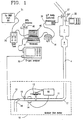
- Fig. 1 shows the overall system as including a flowmeter and gas sampling module 10 adapted for attachment to a tailpipe 4 of a vehicle and a gas analyzer 30 for measuring pollutant concentrations.
- Fig. 1 also shows the vehicle exhaust system as including the tailpipe 4, a muffler 6 and a catalytic converter 7.
- Outputs from the flowmeter and gas sampling module 10 and the gas analyzer 30 are received by an emissions computer 40.
- Emissions computer 40 also receives signals from a keyboard 41 or other user input means.
- a scan tool 70 connects to the OBD or other port 21 of engine computer 20, has a serial output, interprets the data stream from the engine computer 20, and outputs signals to the emissions computer 40.
- the system further includes a separate air/fuel ratio meter 26, which uses a lambda sensor 27 in the exhaust gas stream and/or a global positioning receiver 60.
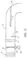
- a straight pipe section 11 serves as a housing for a flow straightener 8 (a plurality of parallel vanes), flow sensing element 13, pressure detector 14, a thermocouple 15, and a closed-end exhaust gas sample tube 12, all in a single assembly which is easily transferable from one vehicle to another.
- Straight pipe section 11 also serves to provide the requisite straight pipe runs upstream and downstream of the flow sensing element 13 as described below.
- the preferred flow sensing element 13 is manufactured by Dieterich Standard of Boulder, Colorado, a subsidiary of Dover Industries, marketed under the tradename ANNUBAR DIAMOND II and is of the differential pressure type.
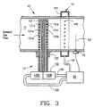
- the flow sensing element 13 includes a probe 131 mounted in the exhaust gas stream perpendicular to the axis of the straight pipe section 11. The exhaust gas flowing around the probe 131 causes a differential pressure to develop between the upstream and downstream sides of the probe 131. The magnitude of the pressure difference is indicative of the exhaust gas flow rate through the straight pipe section 11.
- the probe 131 of the ANNUBAR flow sensing element 13 has a high pressure (upstream) longitudinal channel 131c and a low pressure (downstream) longitudinal channel 131d.
- the probe 131 has a diamond-shaped cross-section and is oriented within straight pipe section 11 so as to present an upstream facing edge 131a and a downstream facing edge 131b.
- the upstream facing edge 131a has a plurality of apertures 131e, spaced along its length and providing fluid communication between the exhaust gas stream and the high pressure channel 131c.
- the downstream facing edge 131b has a plurality of apertures 131f, spaced along its length and providing fluid communication between the exhaust gas and the low pressure channel 131d.
- the spacing of aperatures 131e and of 131f is closer at the ends of probe 131 than at its center.
- the channels 131c and 131d communicate the upstream and downstream pressures to chambers 132A and 132B in the head 132 of the ANNUBAR flow sensing element 13 and from there through lines 134, 135 to a single differential pressure transducer 501 housed within electronic unit 50.
- the pressure transducer 501 is a PX164-010D5V, 0-10" H 2 O differential transducer.
- a "Weld-O-let” which is essentially a threaded steel nipple or lug welded to pipe section 11 to threadably receive and support the probe 131.
- the probe is located both downstream of a straight pipe length "A" and upstream of a second straight pipe length "B", each of sufficient length to ensure straight flow at the probe location.
- a straight pipe length "A" for a pipe section 11 having a diameter (O.D.) of 31 ⁇ 2" or 5", "A” is preferably 34" minimum and "B” is preferably 30" minimum.
- Pipes or tubes having an O.D. of less than 31 ⁇ 2" would have shorter minimum dimensions "A” and "B".
- a 2" O.D. pipe would have a minimum "A" length of 17" and a minimum "B" length of 12".
- Fig. 3 also shows the details of the pressure detector 14 as including an annular jacket 141 and a plurality of 1/16" holes 142 drilled through the wall of pipe section 11 and evenly spaced in a circle around the circumference of pipe section 11 to provide for exhaust gas fluid communication with the interior of jacket 141.
- the exhaust gas pressure is fed via a conduit 142 to a second pressure transducer 502 housed within electronics unit 50.
- Pressure transducer 502 is a PX142-015A5V with a range of 0-15 psia (Abs.).
- thermocouple 15 Temperature of the exhaust gas is detected by a J-type thermocouple 15 having a probe 151 extending into the exhaust gas stream within pipe section 11.
- the thermocouple 15 outputs a nonlinear voltage signal which is converted within electronics unit 50 into a linear voltage signal by a TAC-386-JF converter 503.
- the J-type thermocouple was selected because it offers a large voltage (signal) change per degree of temperature change within the expected temperature range of the exhaust gas.
- Fig. 6 shows the electronics unit 50 as including the pressure transducer 502 (PX142-015A5V 0-15 PSIA Abs), differential pressure transducer 501 (PX164-010D5V 0-10" H 2 O diff.), voltage converter 503 (TAC-386-JF), voltage regulator 505 (LM317T) and LED 507 (RS276-963).
- the pressure transducer 502 PX142-015A5V 0-15 PSIA Abs
- differential pressure transducer 501 PX164-010D5V 0-10" H 2 O diff.
- voltage converter 503 TAC-386-JF
- voltage regulator 505 L317T
- LED 507 RS276-963
- the gas analyzer 30 is a model MT-3505 marketed by Sun/Snap-on. It analyzes and displays the concentrations of HC, CO, C0 2 , O 2 , and NO of the exhaust gas sample as well as engine RPM, temperature sensed by the analyzer thermocouple, and the air/fuel ratio calculated based on the measured exhaust gas constituents.
- the gas concentrations shown on the graphical user interface (GUI) (Fig. 10) will always be the same as those shown on the real analyzer display. Since there is a sample transport time delay between the appearance of the emissions sample at the sample probe and the concentration measurement by the analyzer, the analyzer virtual instrument has a user input for the time delay in seconds. The time delay is applied as shown in Fig. 10.
- the concentration Xi of each of the gaseous pollutants i is continuously measured using the SUN/Snap-on MT-3505 portable emissions analyzer 30 with a built-in sample pump manufactured by SUN/Snap-On.
- the analyzer uses the Non-Dispersive Infrared (NDIR) method for analysis of HC (n-hexane), CO, and C0 2 .
- NDIR Non-Dispersive Infrared
- the analyzer 30 also provides electrochemical NO analysis, and an oxygen sensor is used for determining the oxygen concentration of a gas sample.
- the MT-3505 analyzer 30 In addition to the above-mentioned functions of the MT-3505 analyzer 30, it also calculates the air/fuel ratio of the fuel mixture to the vehicle's engine based on a carbon balance of the exhaust gas components.
- the MT-3505 analyzer also provides for one k-type thermocouple input. This K-type thermocouple is used for measuring the gas sample temperature upon entry to the analyzer for purposes of determining a water vapor correction factor to compensate for the water vapor condensing from the sample along the long sample hose.
- the MT-3505 analyzer 30 is particularly useful as part of a larger emissions testing system since it can be configured to continuously output the measured concentrations in an RS-232 serial data stream.
- a second gas analyzer 32 identical to 30, may be utilized with its sampling probe located upstream of the catalytic converter for the purpose of providing catalyst efficiency checks.
- the probe 12 connected to the sample line of the gas analyzer 30 is a stainless steel tube (3/8" OD) with a sealed distal end and 6 3/32" holes drilled around its circumference, all holes being within 1" of the tip.
- the probe 12 enters through the wall of the steel elbow 16 and is concentric with straight tube section 11.
- the scan tool 70 is a Monitor 4000 Enhanced, marketed by OTC, a division of SPX Corporation. It serves as the means for determination of various vehicle and engine operating parameters including vehicle speeds, engine speed, and in some cases, engine output torque, etc.
- the preferred operating program allows the user to select which ECM data stream items the user wishes to monitor with the associated OTC scan tool.
- the checkbox associated with the desired item causes that item to be selected, displayed, recorded, and to be made available for other calculations.
- Each vehicle has its own associated list of selectable items.
- the "Text to Numbers" arrays substitute numerical values for boolean text values, remove units from the data to be stored to file, etc. Stripping non-numerical characters before saving the data in a file makes the data readily useable in a spreadsheet when the test is finished. A list of all the conversions and deleted characters is recorded in each data file created so the user of the data will know what the conventions were.
- the user also has the option of adding additional boolean text values to convert or units to remove.
- the flowmeter module 10 allows the mass emissions of each regulated pollutant to be calculated on a per second and a per mile basis. Measurement in grams/mile (gm/mi) allows direct comparison to the federal certification testing results obtained using the FTP and to the EPA Emissions standards.
- P i ( t ) is the emission or pollutant i in gm/mi generated at time t
- p i is the density of pollutant i at standard conditions
- X i ( t ) is the measured concentration of pollutant i
- Q s (t) is the volume flow rate of exhaust gas at standard conditions at time t(t)
- v(t) is the vehicle speed on the road in mph at time t. All of the variables are time-dependent.
- h w is the differential pressure from the flow element 131, as sensed by the differential pressure transducer 134 which outputs an analog voltage proportional to h w .
- This signal is converted to digital form by the parallel port A/D converter 16, is subsequently read by the computer 40 through its parallel port, and is then scaled to physical units of pressure by the operating program described below.
- the exhaust temperature T is sensed by the J-type thermocouple 15 mounted in the modular exhaust flowmeter 10.
- the thermocouple voltage is cold-junction compensated, linearized, and amplified by a thermocouple to millivolt converter.
- the output voltage is then input to the parallel port A/D converter 16 and is subsequently read by the computer 40 through its parallel port.
- the analog input voltages read using the A/D converter are all scaled by the operating program to give readouts in physical units of temperature (°F) and pressure (inches H 2 O and inches Hg).
- the necessary scaling values are determined through calibrations of the transducers and are input to the operating program through the GUI as shown on the "Analog Diff. Inputs" section shown in Fig. 10.
- Each flowmeter module is individually calibrated using air by placing it in series with a known flowmeter standard and a vacuum source, such as a blower.
- the flowmeter module electrical connections are made as in a normal test installation so the flow sensor differential pressure and gas absolute pressure and temperature are input to the computer.
- the pressure values and temperature needed for determining the flow of the flow standard are all simultaneously read by the system computer.
- the calibration software determines the flow through the flow standard for each flow rate selected by adjustment of a butterfly valve.
- the constant C' in Equation 2 can then be determined for each flow setting within the range of flows expected for the given flowmeter module. An average of the individual values throughout the expected flow range is used. C' values only differ by very small amounts through the expected range.
- the resultant C' calibration value is unique to the calibrated flowmeter and item of data input to the operating program whenever the associated flowmeter is used for subsequent emissions testing.
- the present invention takes advantage of the capabilities of the Monitor 4000 Enhanced scan tool 70 by interfacing with the scan tool RS232 port with the computer, allowing remote setup and access of the scan tool 70 data stream.
- the system can be configured to monitor the vehicle's speed v, and use this speed as a basis for determining the incremental distance travelled ⁇ d j , by the vehicle over each successive sampling interval ⁇ t j .
- the speed v can be obtained from the data stream of the PATHFINDER TM Trimble Global Position Receiver 60.
- Heavy duty vehicles typically include engine torque in their accessible stream. By multiplying engine torque by engine speed and by time a value for power can be obtained. Accordingly, a mass emission rate for such heavy duty vehicles can be expressed as grams per brake-horsepower-hour.
- the air/fuel ratio is continuously calculated by the MT3505 emissions analyzer 30 based on a carbon balance of the gaseous emissions concentrations.
- the air/fuel ratio may be provided by a separate air/fuel NGK ratiometer 26, employing a lambda sensor.
- the installation of the lambda sensor in the exhaust system should be as close to the exhaust manifold as possible, to maintain the temperature of the sensor above its operating threshold.
- the analog voltage output of the NTK air/fuel ratiometer 26, or any other device with a common analog output, can be connected to the A/D hardware for conversion to digital data read by the computer through its parallel port. This data is then displayed in real time.
- the Global Positioning System (GPS) magnetic mount antenna 60 is marketed by Trimble Navigation and is used in connection with a Trimble PATHFINDER TM GPS PC card 115 and Trimble GPS software which allows the operating program described below (ROVER TM software) to communicate with it, when selected by the user.
- GPS Global Positioning System
- Fig. 4 shows another embodiment of the present invention, similar to the first described embodiment but designed for a diesel powered vehicle with addition of a particulate matter (PM) detector 80.
- a raw exhaust gas sample is drawing through an open-ended and heated sample probe 801 using a vacuum pump 811.
- the raw sample is diluted in a mixer 806 with a precisely metered, variable quantity of filtered air using a mass flow controller 802 before passing through one of two filter banks, each consisting of 2 filters 803, 804 in series.
- Air for dilution is fed to mass flow controller 802 by a dilution air pump 816.
- the diluted sample mass flow is held constant using a second mass flow controller 805.
- the quantity of dilution air is varied in real-time to keep the raw sample mass flow rate proportional to the total exhaust gas mass flow rate to ensure a proportionate sample.
- the diluted mass flow can be controlled by mass flow controller 805 to be proportionate to the total exhaust gas mass flow rate while maintaining proportionality of dilution air by mass flow controller 802.
- the particulate matter remains on the filter in the same way as in the federal procedure.
- the mass increase of the filters 803, 804 at the end of the testing, compared with their initial mass, allows one to determine the particulate mass emissions of the vehicle/engine being tested.
- the raw sample and the dilute sample temperatures are monitored and if either falls below a threshold level the raw sample is heated via the sample probe heater element (see Nichrome Wire 813 in Fig.
- a solid state relay 810 controls a 3-way valve which allows switching of the gas sample flow from probe 801 between (1) a first bank of filters 803 and 804 and (2) a second bank of filters 803 and 804.
- the second bank of filters can also serve as a by-pass for desired pauses in sampling.
- probe 812 includes a sample probe insulated from the nichrome wires 813 embedded in ceramic 814 for heating the probe 812 and an other layer of insulation 815 to reduce heat transfer to the exhaust gases surrounding the probe.
- Fig. 4 further includes the other system components shown in Fig. 1.
- An optical capacity meter 900 (Fig. 4) can also be used in conjunction with the system.
- the smoke meter head 900 optically senses the exhaust gas opacity and transmits analog voltage signals to the A/D converter 16 for transmission to computer 40.
- a Telonic Berkeley Model 300 instrument is preferably used as the smoke meter or optical density meter 900.
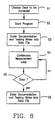
- FIG. 8 A preferred embodiment of a program for operation of the system of the present invention is illustrated by the flow chart shown in Figs. 8 and 9.
- the flow chart of Fig. 8 illustrates the preferred main operating program (ROVER TM software) for operation of the emissions reporting system after installation on the vehicle to the tested.
- the operator designates which data is to be collected by means of the available selections of the graphical user interface shown in Fig. 10 (step S1).
- a documentation window opens allowing the technician to enter notes concerning the vehicle and test to be performed (step S3).
- the notes are input using the computer keyboard 41.
- the documentation window closes and the program continuously acquires the desired data and performs the necessary calculations (step S4) and displays the emissions and vehicle data on the computer screen and in a stored computer file.
- the program continues in this mode of operation (loop of S4) until stopped by the operator.
- the user documentation window reopens on the computer screen to allow entry of post-test documentation and notes concerning the vehicle and test just conducted (step S6).
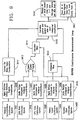
- Fig. 9 illustrates the subroutine for the "Continuous Measurement Loop (S4) of Fig. 8.
- S4 Continuous Measurement Loop
- a set frequency typically 1Hz
- raw data is collected from each of the sources S401-S405 as shown. Since there are small, known characteristic time delays associated with each of the sources, time-based adjustments are applied as shown (S406-S410). Additionally, the gas concentrations measured by the analyzer are corrected for water vapor condensation which takes place along the sample hose en route to the analyzer (S411). Exhaust gas flow at standard conditions is determined according to Equation 4 using the analog input voltages scaled to the appropriate physical units (S412).
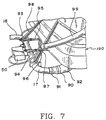
- Fig. 7 shows the flowmeter/gas sampling probe module 10 mounted on the rear of a passenger vehicle 100.
- An example of the connection means for connecting the module 10 of the present invention to the exhaust pipe 101 of vehicle 100 is shown as the combination of steel pipe elbow 17, clamped to the upstream end of straight pipe section 11, and an elastomeric boot 90 which is connected to the upstream end of elbow 17 and to the exhaust pipe 101 by hose clamps 91 and 92.
- the elastomeric boot may be a high-temperature resistant silicone rubber tube of the type used to connect a vehicle exhaust pipe to a conventional (stationary) test stand used in emissions testing.
- An insulated conduit 99 carries the sample tube from the module 10 to the gas analyzer 30 and leads from the pressure transducers 501, 502, thermocouple 15, etc. to the A/D converter 16 and then to computer 40.
- the means for supporting the module of the present invention is seen in Fig. 7 as a pair of pipe hangers 93, 94 which, in turn, are supported by rods 95, 96 connected to the chassis of vehicle 100. Rubber straps 97, 98 serve to provide further support for the module 10. Other means may be used to secure the flowmeter modules consistent with safety.
Abstract
Description
Claims (17)
- A real-time, mobile, on-board vehicle emission reporting system comprising:a flowmeter (10) for directly detecting actual flow rate of exhaust gas during road travel;support means (11, 93, 94, 95, 96) for supporting said flowmeter (10) on-board the vehicle;a gas analyzer (30) for detecting concentration of each of a plurality of gaseous pollutants within the exhaust gas; andcalculating means (40) for calculating and reporting mass flow rates for the gaseous pollutants in real-time based on the directly measured flow rate of the exhaust gas and on the detected concentrations.
- A mobile vehicle on-board emissions testing system, said system comprising:a module (10) for detachably mounting on a vehicle (100) to be tested and containing a flow sensing element (13);support means (93, 94, 95, 96) for attaching said module to a body portion of the vehicle;connection means (17, 90, 91, 92) for detachably connecting said module (10) to an exhaust pipe (101) of the vehicle, whereby actual flow rate of exhaust gas of the vehicle (100) is directly detected by said flow sensing element (13);a downstream sampling tube (12) for continuously sampling the exhaust gas of the vehicle (100);a downstream gas analyzer (30) for detecting concentration of each of a plurality of gaseous pollutants within the exhaust gas sampled through said downstream sample tube (12); andcalculating means (40) for calculating mass flow rates for each of said gaseous pollutants based on the detected concentrations and the detected flow rate of the exhaust gas.
- A mobile vehicle on-board emissions testing system according to claim 2 wherein said connection means comprises an elastomeric boot (90).
- A mobile vehicle on-board emissions testing system according to claim 2 wherein said sampling tube (12) is fixed within said module (10).
- A mobile vehicle on-board emissions testing system according to claim 2 further comprising:an upstream sampling tube (321) for continuously sampling the exhaust gas of the vehicle upstream of a catalytic converter (7), said downstream sampling tube (12) being located downstream of the catalytic converter (7); andan upstream gas analyzer (32) for detecting concentrations of each of said plurality of gaseous pollutants, said calculating means (40) determining an efficiency for the catalytic converter (7) by comparing the concentrations detected by said upstream gas analyzer (32) with the concentrations detected by said downstream gas analyzer (30).
- A mobile vehicle on-board emissions testing system according to claim 2 additionally comprising:an open-ended gas sampling tube (801), mounted within said module (10), for continuously sampling the exhaust gas inclusive of particulates; andat least one removably mounted filter element (803, 804) whereby said one filter element may be weighed before and after a known period of time during which exhaust gas from said open-ended sampling tube (801) is passed through said one filter element (803, 804).
- The invention according to claim 1 or 2 wherein mass flow rates are each calculated as a unit mass of gaseous pollutant per unit distance travelled and further comprising distance detecting means (60 or 70) for continuously detecting distance travelled by the vehicle (100).
- A mobile vehicle on-board emissions testing system according to claim 7 wherein said distance detecting means is a scan tool (70) which receives data from an engine computer (80) on-board the vehicle (100) and which transmits the received data to said calculating means (40).
- A mobile vehicle on-board emissions testing system according to claim 2 wherein said calculating means (40), based on the data received from the scan tool (70) , correlates the calculated mass flow rates with at least one engine operating parameter.
- A mobile vehicle on-board emissions testing system according to claim 2 additionally comprising:wherein said calculating means (40) repeatedly computes present position of the vehicle (100) based on the signals from said receiver and correlates the computed present positions with the calculated mass flow rates of said pollutants.a global positioning system receiver (60) for continuously receiving signals for use in calculating present position of the vehicle (100); and
- A mobile vehicle on-board emissions testing system according to claim 2 wherein said calculating means (40) also calculates fuel economy in real time.
- A mobile vehicle on-board emissions testing system according to claim 2 further comprising support means (93, 94, 95, 96) for attaching and fixing said module (10) to a body portion of the vehicle (100)
- A mobile vehicle on-board emissions testing system according to claim 2 wherein said module comprises:a module housing including a straight pipe section (11) having an open interior;a flow sensing element (13) mounted within said straight pipe section (11) for determining the velocity of the exhaust gas flow through the open interior of said straight pipe section (11); anda gas sampling tube (12) extending into said open interior at a position fixed relative to said flow sensing element (12) for obtaining a sample of the exhaust gas and for feeding the sample to the downstream gas analyzer (30).
- A flowmeter module (10) for connection to an exhaust pipe of a vehicle (100) in on-road driving, said flowmeter module (10) comprising:a module housing including a straight pipe section (11) having an open interior with a cross-section of diameter D;support means (93, 94, 95, 96) for attaching said straight pipe section (11) to a body portion of the vehicle (100);connection means (17, 90, 91, 92) for connecting one end of said straight pipe section (11) to the exhaust pipe (101) to provide an exhaust gas flow from the exhaust pipe (101) through said open interior;a flow sensing element (13) mounted within said straight pipe section (11) for determining the velocity of the exhaust gas flow through the open interior of said straight pipe section (11); anda gas sampling tube (12) extending into said open interior at a position fixed relative to said flow sensing element (13) for obtaining a sample of the exhaust gas and for feeding the sample to a gas analyzer (30).
- A flowmeter module (10) according to claim 14 wherein said flow sensing element (13) comprises a bar (131) extending into said open interior and across at least a major portion of diameter D, said bar (131) having a first row of openings (131e) facing an upstream end of said straight pipe section (11) and providing for communication of the exhaust gas with a first channel (131c) extending longitudinally within said bar (131) and a second row of openings (131f) facing a downstream end of said straight pipe section (11) and providing for communication of the exhaust gas with a second channel (131d) extending longitudinally within said bar (131); and
pressure transducer means (501) for detecting a differential between upstream and downstream pressures, respectively within said first and second channels (131c, 131d). - The invention according to claim 15 wherein said module further comprises:a pressure detector (14) for detecting pressure of the exhaust gas flow adjacent said flow sensing element (13);a temperature probe (15) for detecting temperature of the exhaust gas flow adjacent said flow sensing element (13) ; andcalculating means (40) for calculating a gas flow rate based on a differential between said upstream and downstream pressures and for correcting the calculated gas flow rate based on the detected temperature and the detected pressure.
- The invention according to claim 16 wherein said pressure detector (14) comprises an annular jacket (141) sealed around the exterior of said straight pipe section (11) and a plurality of holes (142) extending through said straight pipe section (11) and arranged in a circle around a circumference of said straight pipe section (11), said plurality of holes (142) providing fluid communication between said open interior and said annular jacket (141) and a pressure transducer (50) in fluid communication with said annular jacket (141).
Applications Claiming Priority (3)
| Application Number | Priority Date | Filing Date | Title |
|---|---|---|---|
| US7048398P | 1998-01-05 | 1998-01-05 | |
| US70483P | 1998-01-05 | ||
| PCT/US1999/000036 WO1999035480A1 (en) | 1998-01-05 | 1999-01-05 | Real-time on-road vehicle exhaust gas modular flowmeter and emissions reporting system |
Publications (2)
| Publication Number | Publication Date |
|---|---|
| EP1046025A1 EP1046025A1 (en) | 2000-10-25 |
| EP1046025B1 true EP1046025B1 (en) | 2004-05-26 |
Family
ID=22095569
Family Applications (1)
| Application Number | Title | Priority Date | Filing Date |
|---|---|---|---|
| EP99900734A Expired - Lifetime EP1046025B1 (en) | 1998-01-05 | 1999-01-05 | Real-time on-road vehicle exhaust gas modular flowmeter and emissions reporting system |
Country Status (13)
| Country | Link |
|---|---|
| US (2) | US6148656A (en) |
| EP (1) | EP1046025B1 (en) |
| JP (2) | JP4294863B2 (en) |
| KR (1) | KR20010033882A (en) |
| CN (2) | CN100570314C (en) |
| AT (1) | ATE268007T1 (en) |
| AU (1) | AU746060B2 (en) |
| CA (1) | CA2316158C (en) |
| DE (1) | DE69917594T2 (en) |
| MX (1) | MXPA00006616A (en) |
| RU (1) | RU2224233C2 (en) |
| TR (1) | TR200001900T2 (en) |
| WO (1) | WO1999035480A1 (en) |
Cited By (3)
| Publication number | Priority date | Publication date | Assignee | Title |
|---|---|---|---|---|
| CN102435443A (en) * | 2011-09-08 | 2012-05-02 | 中国汽车技术研究中心 | Quick ageing data acquisition system of automobile catalyst |
| EP2848912A1 (en) | 2013-09-13 | 2015-03-18 | AVL List GmbH | Mobile exhaust gas measuring device |
| DE102012215983B4 (en) | 2011-09-21 | 2024-02-22 | GM Global Technology Operations, LLC (n.d. Ges. d. Staates Delaware) | Method for simulating various engine operating conditions to evaluate engine emissions testing equipment |
Families Citing this family (118)
| Publication number | Priority date | Publication date | Assignee | Title |
|---|---|---|---|---|
| US6470732B1 (en) * | 1998-01-05 | 2002-10-29 | The United States Of America As Represented By The Administrator Of The National Aeronautics And Space Administration | Real-time exhaust gas modular flowmeter and emissions reporting system for mobile apparatus |
| DE69917594T2 (en) * | 1998-01-05 | 2005-06-23 | United States Environmental Protection Agency | MODULAR REAL-TIME EXHAUST GAS FLOWMETER FOR DRIVING VEHICLES AND REPORTING SYSTEM FOR EMISSIONS |
| US6308130B1 (en) * | 1999-07-23 | 2001-10-23 | Clean Air Technologies International, Inc. | Portable on-board mass emissions measuring system |
| WO2001046689A1 (en) * | 1999-12-22 | 2001-06-28 | Propulsion Controls Engineering | Method and system for tracking engine emissions as a function of geographical location |
| JP2001249065A (en) * | 1999-12-28 | 2001-09-14 | Ono Sokki Co Ltd | Exhaust gas diluting device |
| DE10004941A1 (en) * | 2000-02-06 | 2001-08-09 | Reimer Offen | Tempered liquid sampler |
| US6594989B1 (en) * | 2000-03-17 | 2003-07-22 | Ford Global Technologies, Llc | Method and apparatus for enhancing fuel economy of a lean burn internal combustion engine |
| US6435019B1 (en) * | 2000-04-18 | 2002-08-20 | Clean Air Technologies International, Inc. | Portable on-board system for measuring vehicle exhaust particulate emissions |
| US6840095B1 (en) * | 2000-04-26 | 2005-01-11 | Bombardier Recreational Products Inc. | Exhaust diaphragm assembly |
| US20020026822A1 (en) * | 2000-07-26 | 2002-03-07 | Reading Andrew R. | Vehicle gas emission sampling and analysis assembly |
| JP4399094B2 (en) * | 2000-08-09 | 2010-01-13 | 株式会社堀場製作所 | Exhaust gas sampling device |
| DE10039965A1 (en) * | 2000-08-16 | 2002-02-28 | Siemens Ag | Method and arrangement for exhaust gas analysis on motor vehicles with on-board engine control and diagnostic system |
| US6636798B2 (en) | 2001-01-31 | 2003-10-21 | Csxt Intellectual Properties Corporation | Locomotive emission reduction kit and method of earning emission credits |
| US6470844B2 (en) * | 2001-01-31 | 2002-10-29 | Csx Transportation, Inc. | System and method for supplying auxiliary power to a large diesel engine |
| JP2002214082A (en) * | 2001-01-24 | 2002-07-31 | Tsukasa Sokken Co Ltd | Simultaneity correction apparatus for ensuring simultaneity in measurement of mass emission or fuel consumption quantity by high speed continuous measurement of flow rate and composition of exhaust gas |
| US6928972B2 (en) * | 2001-01-31 | 2005-08-16 | Csxt Intellectual Properties Corporation | Locomotive and auxiliary power unit engine controller |
| JP3711329B2 (en) * | 2001-02-01 | 2005-11-02 | ミヤマ株式会社 | Vehicle operating state evaluation system |
| US6481299B2 (en) * | 2001-03-23 | 2002-11-19 | Avl North America Inc. | Particulate sampling probe and dilution tunnel |
| US6775602B2 (en) | 2001-07-09 | 2004-08-10 | Gordon-Darby Systems, Inc. | Method and system for vehicle emissions testing through on-board diagnostics unit inspection |
| US7660934B2 (en) * | 2001-08-28 | 2010-02-09 | Dearborn Group, Inc. | ASCII gateway to in-vehicle networks |
| US6575012B1 (en) * | 2001-11-02 | 2003-06-10 | Ford Global Technologies, Llc | Method and apparatus for measuring a gaseous component emanating from a vehicle |
| DE10203728A1 (en) * | 2002-01-30 | 2003-08-14 | Bosch Gmbh Robert | Electronic exchange protection of exhaust gas measuring probes in an exhaust gas aftertreatment internal combustion engine, in particular of a motor vehicle |
| US6823268B2 (en) * | 2002-02-04 | 2004-11-23 | Avl North America Inc. | Engine exhaust emissions measurement correction |
| US6973525B2 (en) * | 2002-03-19 | 2005-12-06 | Dell Products L.P. | System and method for managing bus numbering |
| US6739184B2 (en) * | 2002-04-12 | 2004-05-25 | Honda Giken Kogyo Kabushiki Kaisha | Method and apparatus for measuring effects of exhaust gas recirculation deposits |
| GB0221221D0 (en) * | 2002-09-13 | 2002-10-23 | Delphi Tech Inc | Exhaust gas sensor |
| US6865472B2 (en) * | 2002-09-27 | 2005-03-08 | Horiba Ltd. | Vehicle-installed exhaust gas analyzing apparatus |
| JP3899004B2 (en) * | 2002-09-27 | 2007-03-28 | 株式会社堀場製作所 | In-vehicle HC measuring device |
| JP2004150864A (en) * | 2002-10-29 | 2004-05-27 | Toyota Motor Corp | Emission treatment device |
| US6796165B2 (en) * | 2002-11-18 | 2004-09-28 | Southwest Research Institute | Apparatus and method for real-time measurement of mass, size and number of solid particles of particulate matter in engine exhaust |
| US7555928B2 (en) * | 2002-12-05 | 2009-07-07 | Avl North America Inc. | Exhaust volume measurement device |
| EP1467194B2 (en) | 2003-04-11 | 2021-11-03 | Testo SE & Co. KGaA | Process and apparatus for detecting, characterising and/or eliminating particles |
| JP4222101B2 (en) * | 2003-05-16 | 2009-02-12 | トヨタ自動車株式会社 | Gas measuring method and gas measuring device |
| CA2531602A1 (en) * | 2003-07-09 | 2005-01-27 | U.S. Environmental Protection Agency | Vehicle on-board reporting system for state emissions test |
| CA2476902C (en) * | 2003-08-20 | 2014-04-22 | Dennis S. Prince | Innovative gas monitoring with spacial and temporal analysis |
| JP2005067531A (en) * | 2003-08-27 | 2005-03-17 | Denso Corp | Vehicular air-conditioner |
| US20050160788A1 (en) * | 2004-01-28 | 2005-07-28 | Juraj Krajci | Method and apparatus for power management |
| WO2005085793A1 (en) * | 2004-03-04 | 2005-09-15 | Ernst Pucher | Device and method for determining the mass emission of at least one exhaust gas component in a vehicle situated in traffic |
| JP2005273613A (en) * | 2004-03-26 | 2005-10-06 | Hino Motors Ltd | Sensing method for obd of exhaust gas |
| US7568383B2 (en) * | 2004-05-24 | 2009-08-04 | Ford Global Technologies, Llc | Portable vehicle exhaust flow sensor |
| US20050274169A1 (en) * | 2004-06-10 | 2005-12-15 | James Butler | Vehicle/engine sampling system for precise analysis of exhaust components |
| US20050274899A1 (en) * | 2004-06-10 | 2005-12-15 | James Butler | Spectroscopic system and method for analysis in harsh, changing environments |
| CN100427952C (en) * | 2004-09-28 | 2008-10-22 | 佛山分析仪有限公司 | Measuring device and its method for motor vehicle exhaust pollutant total amount |
| CN101253394B (en) * | 2005-07-14 | 2012-01-25 | 西斯泰克控制测量及工程股份有限公司 | Stamping probe |
| US7765792B2 (en) | 2005-10-21 | 2010-08-03 | Honeywell International Inc. | System for particulate matter sensor signal processing |
| AT8308U3 (en) * | 2005-12-29 | 2007-01-15 | Ditest Fahrzeugdiagnose Gmbh | METHOD AND DEVICE FOR EXHAUST SEARCH AT DIESEL ENGINES |
| US7299690B2 (en) * | 2006-04-26 | 2007-11-27 | Caterpillar Inc. | Particulate sampling system and method |
| KR100805581B1 (en) * | 2006-08-14 | 2008-02-20 | 삼성에스디아이 주식회사 | Fuel cell system with cantilever velocity sensor |
| KR20080024803A (en) * | 2006-09-15 | 2008-03-19 | 에스케이에너지 주식회사 | A system for monitoring dpf using wireless communication |
| US20080211730A1 (en) | 2007-01-26 | 2008-09-04 | Woosnam Calvin H | Gimbaled Mount System for Satellites |
| US20090226177A1 (en) * | 2007-01-26 | 2009-09-10 | Woosnam Calvin H | Communications Cable and Method of Making Same |
| WO2008136360A1 (en) * | 2007-04-27 | 2008-11-13 | Horiba, Ltd. | Exhaust gas analyzer |
| US20080312786A1 (en) * | 2007-06-14 | 2008-12-18 | Qualcomm Incorporated | Wireless on-board diagnostics for heavy duty trucks |
| US7580808B2 (en) * | 2007-09-11 | 2009-08-25 | Gm Global Technology Operations, Inc. | Onboard trip computer for emissions subject to reduction credits |
| US7382244B1 (en) | 2007-10-04 | 2008-06-03 | Kd Secure | Video surveillance, storage, and alerting system having network management, hierarchical data storage, video tip processing, and vehicle plate analysis |
| US8013738B2 (en) | 2007-10-04 | 2011-09-06 | Kd Secure, Llc | Hierarchical storage manager (HSM) for intelligent storage of large volumes of data |
| US7414726B1 (en) * | 2007-10-31 | 2008-08-19 | Bambeck Robert J | Gas analyzer systems and methods |
| US20090222280A1 (en) * | 2008-02-29 | 2009-09-03 | Shiva Mittal | System and method for certification data management |
| US7946160B2 (en) * | 2008-10-09 | 2011-05-24 | GM Global Technology Operations LLC | Portable emissions measurement adapter device |
| US8280646B2 (en) * | 2009-02-25 | 2012-10-02 | Bayerische Motoren Werke Aktiengesellschaft | Vehicle CO2 emission offsetting system and method |
| US8055437B2 (en) * | 2009-03-17 | 2011-11-08 | Ford Global Technologies, Llc | CO2 information display and method |
| CA2764010C (en) * | 2009-06-05 | 2018-07-10 | Xtralis Technologies Ltd | Gas detector apparatus |
| FR2949390B1 (en) * | 2009-08-31 | 2012-12-14 | Peugeot Citroen Automobiles Sa | GAS EXHAUST DEVICE GENERATED BY ELECTRICAL ACCUMULATORS OF A HYBRID VEHICLE |
| US20110184784A1 (en) * | 2010-01-27 | 2011-07-28 | Trimble Navigation Limited | Tracking Carbon Footprints |
| MY150333A (en) * | 2010-03-08 | 2013-12-31 | Conducta Endress & Hauser | Measuring device for use in a biogas plant |
| US20110239209A1 (en) | 2010-03-23 | 2011-09-29 | Fujitsu Limted | System and methods for remote maintenance in an electronic network with multiple clients |
| US9286485B2 (en) * | 2010-03-23 | 2016-03-15 | Fujitsu Limited | Using trust points to provide services |
| EP3517746B1 (en) | 2010-08-06 | 2020-10-07 | AVL Test Systems, Inc. | Particulate measurement system |
| US8612115B2 (en) | 2010-08-30 | 2013-12-17 | Corning Incorporated | Methods for controlling the operation of a particulate filter |
| CA2830217C (en) * | 2011-03-16 | 2018-04-24 | Global Mrv, Inc. | Emissions measuring system |
| KR101184384B1 (en) * | 2011-06-21 | 2012-09-20 | 서종혁 | System for changing carbon emissions of greenhouse gas emissions and method therefor |
| CN102435441B (en) * | 2011-09-08 | 2014-07-09 | 中国汽车技术研究中心 | Data acquisition system for emission parameter of moving vehicle |
| EP2568139B1 (en) * | 2011-09-12 | 2016-07-13 | Cummins Emission Solutions, Inc. | Integrated connection device for connecting several sensors |
| RU2492444C2 (en) * | 2011-10-07 | 2013-09-10 | Юрий Валерьевич Брусиловский | Automated system for monitoring exhaust gases of processing plants |
| CN102518497A (en) * | 2011-12-20 | 2012-06-27 | 清华大学 | Engine exhaust parameter detecting device for matching muffler with engine |
| US10563606B2 (en) * | 2012-03-01 | 2020-02-18 | Ford Global Technologies, Llc | Post catalyst dynamic scheduling and control |
| GB2501930B (en) * | 2012-05-11 | 2018-11-14 | Ford Global Tech Llc | Engine out emission control system and method |
| KR20150023718A (en) * | 2012-06-11 | 2015-03-05 | 에이브이엘 테스트 시스템즈, 인코포레이티드 | Exhaust sampling system and method for synchronizing time alignment and dilation |
| US9279406B2 (en) | 2012-06-22 | 2016-03-08 | Illinois Tool Works, Inc. | System and method for analyzing carbon build up in an engine |
| CN102829976B (en) * | 2012-08-20 | 2015-04-15 | 清华大学 | Simulator stand for exhaust characteristics of vehicle engine |
| US20140250865A1 (en) * | 2013-03-07 | 2014-09-11 | Cummins Ip, Inc. | Exhaust gas aftertreatment bypass system and methods |
| JP6116360B2 (en) * | 2013-05-16 | 2017-04-19 | 株式会社堀場製作所 | Exhaust gas flow meter and exhaust gas analysis system |
| JP6155138B2 (en) * | 2013-05-22 | 2017-06-28 | 株式会社堀場製作所 | Fuel consumption measuring device |
| JP6122733B2 (en) * | 2013-08-12 | 2017-04-26 | 株式会社堀場製作所 | Fuel consumption calculation device, fuel consumption calculation program, and fuel consumption measurement device |
| DE202014006185U1 (en) | 2013-08-12 | 2014-11-26 | Horiba Ltd. | Fuel consumption calculation unit, fuel consumption calculation program, fuel consumption meter and exhaust gas meter |
| JP6199167B2 (en) * | 2013-11-28 | 2017-09-20 | 株式会社堀場製作所 | Exhaust gas measuring device and exhaust gas measuring program |
| DE102013217382A1 (en) * | 2013-08-30 | 2015-03-05 | Rolls-Royce Deutschland Ltd & Co Kg | Measuring device and method for measuring a mass flow of a fluid |
| US9970372B2 (en) * | 2014-02-14 | 2018-05-15 | Ford Global Technologies, Llc | Method of diagnosing an exhaust gas sensor |
| JP6317702B2 (en) * | 2014-05-19 | 2018-04-25 | 株式会社堀場製作所 | Road test equipment |
| DE102014014557B4 (en) * | 2014-09-30 | 2016-09-29 | Paragon Ag | Sensor arrangement for detecting the CO2 concentration in an interior space |
| JP6290771B2 (en) | 2014-11-14 | 2018-03-07 | 日本特殊陶業株式会社 | Measuring device |
| GB201420649D0 (en) * | 2014-11-20 | 2015-01-07 | Nicoventures Holdings Ltd | Apparatus and methods for monitoring aerosol delivery |
| CN105043401B (en) * | 2015-07-14 | 2018-04-03 | 南京理工大学 | City health trip method and system for planning based on Floating Car method |
| GB201519926D0 (en) * | 2015-11-11 | 2015-12-23 | Horiba Mira Ltd | Emmissions testing system |
| JP6791512B2 (en) * | 2016-02-12 | 2020-11-25 | ブレトン、レオ | Real-time fluid type mass flow meter |
| JP6306626B2 (en) * | 2016-03-09 | 2018-04-04 | 本田技研工業株式会社 | Leak detection method and open emission analyzer for open emission analysis |
| CN105806627A (en) * | 2016-03-15 | 2016-07-27 | 南京汽车集团有限公司 | Vehicle-mounted emission testing device and testing method thereof |
| CN105912862B (en) * | 2016-04-12 | 2018-07-27 | 北京荣之联科技股份有限公司 | A kind of exhaust emissions quantity measuring method and air pollution analysis method and apparatus |
| DE102016218815B4 (en) | 2016-09-29 | 2020-07-30 | Audi Ag | Procedure for selecting a route for an emission test |
| CN106770973A (en) * | 2017-01-18 | 2017-05-31 | 广西三原高新科技有限公司 | A kind of portable car-mounted discharge detecting system and detection method |
| JP2018115997A (en) * | 2017-01-19 | 2018-07-26 | 株式会社堀場製作所 | Exhaust gas flow rate measurement unit and exhaust gas analysis device |
| RU172095U1 (en) * | 2017-01-27 | 2017-06-28 | Леонид Григорьевич Кузнецов | Device for monitoring the oil content in compressed gas |
| FR3064363B1 (en) * | 2017-03-27 | 2021-07-23 | Action Europe | PORTABLE DEVICE FOR THE DETECTION AND SAMPLING OF POLLUTANTS IN A GAS AND PROCESS IMPLEMENTED BY THIS DEVICE |
| US10416042B2 (en) * | 2017-07-20 | 2019-09-17 | Volvo Truck Corporation | Engine exhaust emissions monitoring device |
| JP7011914B2 (en) | 2017-09-19 | 2022-01-27 | 日本特殊陶業株式会社 | Particle detection system |
| DE102017216992B4 (en) * | 2017-09-26 | 2024-03-21 | Bayerische Motoren Werke Aktiengesellschaft | Method for determining a pollutant concentration in exhaust gases and for determining emission masses in exhaust gases and measuring system for exhaust gas measurement |
| CN107894399A (en) * | 2017-12-27 | 2018-04-10 | 西南林业大学 | A kind of Portable agricultural tractor N2O discharges detecting system and detection method |
| US10823593B2 (en) | 2018-03-09 | 2020-11-03 | Sensors, Inc. | Engine exhaust flow measurement with pulsation compensation |
| CN108730003A (en) * | 2018-03-27 | 2018-11-02 | 盐城工业职业技术学院 | Based on the automobile tail gas monitoring system and its monitoring method under transport condition |
| JP2019184318A (en) * | 2018-04-04 | 2019-10-24 | 日本特殊陶業株式会社 | Concentration detector |
| CN108760591A (en) * | 2018-04-10 | 2018-11-06 | 天津世纪动力科技发展有限公司 | A kind of Vehicular exhaust contaminant measurement device |
| US11143644B2 (en) * | 2018-06-22 | 2021-10-12 | Avl Test Systems, Inc. | System and method for determining a contamination level in an emissions measurement device or system |
| US20220112698A1 (en) * | 2018-11-19 | 2022-04-14 | Gould Instruments Pty Ltd | A testing device for backflow prevention devices |
| CN110067625A (en) * | 2019-05-30 | 2019-07-30 | 广西玉柴机器股份有限公司 | A kind of device of quick detection natural gas engine DS NOx Est |
| CN114112420A (en) * | 2020-09-01 | 2022-03-01 | 上海汽车集团股份有限公司 | Vehicle nitrogen oxide emission testing method and related device |
| CN112964609A (en) * | 2021-01-25 | 2021-06-15 | 国网冀北电力有限公司电力科学研究院 | On-site detection system for smoke pollutants of stove |
| CN113256966B (en) * | 2021-04-21 | 2022-02-25 | 中国科学技术大学先进技术研究院 | Method and system for establishing road network emission list based on space-time velocity domain reconstruction |
| WO2023064423A1 (en) * | 2021-10-12 | 2023-04-20 | 3Datx Corporation | Emissions testing device for periodic technical inspection |
Family Cites Families (33)
| Publication number | Priority date | Publication date | Assignee | Title |
|---|---|---|---|---|
| US2782103A (en) * | 1951-10-12 | 1957-02-19 | Phillips Petroleum Co | Analyzer for gaseous mixtures |
| AT266497B (en) * | 1963-09-12 | 1968-11-25 | Bosch Gmbh Robert | Electrical measuring device |
| US3406562A (en) | 1966-01-14 | 1968-10-22 | Gen Motors Corp | On-line exhaust data analysis system |
| US3427630A (en) * | 1967-04-21 | 1969-02-11 | George C Imes | Fluid pressure recorder |
| US3603155A (en) * | 1970-02-02 | 1971-09-07 | Chromalloy American Corp | Method and apparatus for mass emission sampling of motor vehicle exhaust gases |
| US3999425A (en) * | 1973-02-15 | 1976-12-28 | Lars Collin Consult Ab | Method and apparatus for preforming exhaust gas emission tests with vehicle engines |
| DE2938653A1 (en) * | 1979-09-25 | 1981-03-26 | Daimler-Benz Aktiengesellschaft, 70567 Stuttgart | Monitoring vehicle exhaust emission while on dynamometer - using regulated exhaust extraction to collector via three=way valve |
| JPS5817529U (en) * | 1981-07-28 | 1983-02-03 | 日本鋼管株式会社 | Pressure extractor for measuring pressure inside powder and granule transport pipes |
| JPS62157546A (en) * | 1985-12-31 | 1987-07-13 | Horiba Ltd | Modal mass analysis for automobile emission gas |
| JP2525912Y2 (en) * | 1989-06-02 | 1997-02-12 | 株式会社椿本チエイン | Oil bath electric cylinder |
| DE8915832U1 (en) * | 1989-07-18 | 1991-09-05 | Gutmann Messtechnik Ag, Hergiswil, Ch | |
| JPH0373840A (en) * | 1989-08-15 | 1991-03-28 | Nissan Motor Co Ltd | Instrument for measuring nox exhausting quantity |
| US5099680A (en) * | 1990-05-03 | 1992-03-31 | Sensors, Inc. | Method of analyzing vehicle emissions and in-flight gas analysis apparatus |
| JPH04231868A (en) * | 1990-05-14 | 1992-08-20 | Siemens Ag | Discharged-gas analyzing apparatus |
| JP2553013Y2 (en) * | 1991-03-06 | 1997-11-05 | 本田技研工業株式会社 | Exhaust auxiliary pipe |
| US5184501A (en) * | 1991-05-03 | 1993-02-09 | Horiba Instruments Incorporated | Exhaust sampler and control means |
| US5163613A (en) * | 1991-06-03 | 1992-11-17 | Ragan Alton R | Thermostat bypass |
| US5410907A (en) * | 1993-08-25 | 1995-05-02 | White Consolidated Ind Inc | Gas sampling method and dilution tunnel therefor |
| US5418366A (en) * | 1994-05-05 | 1995-05-23 | Santa Barbara Research Center | IR-based nitric oxide sensor having water vapor compensation |
| US5550737A (en) * | 1993-11-05 | 1996-08-27 | Environmental Systems Products, Inc. | Method for analysis of vehicle performance characteristics |
| US5709082A (en) * | 1994-06-27 | 1998-01-20 | General Motors Corporation | Modulation schemes for on-board diagnostic exhaust system |
| JPH08284787A (en) * | 1995-04-18 | 1996-10-29 | Horiba Ltd | Exhaust gas controller for vehicle |
| GB9512929D0 (en) * | 1995-06-24 | 1995-08-30 | Sun Electric Uk Ltd | Multi-gas sensor systems for automatic emissions measurement |
| US5711021A (en) * | 1995-08-07 | 1998-01-20 | Snap-On Technologies, Inc. | Method for graphically displaying vehicle test data |
| US5756360A (en) * | 1995-09-29 | 1998-05-26 | Horiba Instruments Inc. | Method and apparatus for providing diluted gas to exhaust emission analyzer |
| US5639957A (en) * | 1995-10-12 | 1997-06-17 | Snap-On Technologies, Inc. | Method and apparatus for performing modal mass analysis of exhaust gas from motor vehicle |
| EP0855578A3 (en) * | 1997-01-25 | 1998-11-18 | Horiba, Ltd. | Exhaust gas flow measuring equipment of internal combustion engine and process for calibrating sensitivity of trace gas flow meter |
| US6112574A (en) * | 1997-01-25 | 2000-09-05 | Horiba Ltd | Exhaust gas analyzer and modal mass analysis method by gas trace process using the analyzer thereof |
| JPH10267721A (en) * | 1997-01-25 | 1998-10-09 | Horiba Ltd | Exhaust gas flow measuring device for internal combustion engine |
| US5918256A (en) * | 1997-10-27 | 1999-06-29 | Delaney; William O. | Motor vehicle emission analysis system |
| DE69917594T2 (en) * | 1998-01-05 | 2005-06-23 | United States Environmental Protection Agency | MODULAR REAL-TIME EXHAUST GAS FLOWMETER FOR DRIVING VEHICLES AND REPORTING SYSTEM FOR EMISSIONS |
| US6085582A (en) * | 1998-04-29 | 2000-07-11 | Sensors, Inc. | Vehicle mass emission measurement |
| US6308130B1 (en) * | 1999-07-23 | 2001-10-23 | Clean Air Technologies International, Inc. | Portable on-board mass emissions measuring system |
-
1999
- 1999-01-05 DE DE69917594T patent/DE69917594T2/en not_active Expired - Lifetime
- 1999-01-05 EP EP99900734A patent/EP1046025B1/en not_active Expired - Lifetime
- 1999-01-05 US US09/226,920 patent/US6148656A/en not_active Expired - Lifetime
- 1999-01-05 CA CA002316158A patent/CA2316158C/en not_active Expired - Fee Related
- 1999-01-05 RU RU2000120617/06A patent/RU2224233C2/en not_active IP Right Cessation
- 1999-01-05 WO PCT/US1999/000036 patent/WO1999035480A1/en not_active Application Discontinuation
- 1999-01-05 CN CNB200610142147XA patent/CN100570314C/en not_active Expired - Fee Related
- 1999-01-05 JP JP2000527814A patent/JP4294863B2/en not_active Expired - Fee Related
- 1999-01-05 AU AU20250/99A patent/AU746060B2/en not_active Ceased
- 1999-01-05 MX MXPA00006616A patent/MXPA00006616A/en not_active IP Right Cessation
- 1999-01-05 KR KR1020007007453A patent/KR20010033882A/en active Search and Examination
- 1999-01-05 TR TR2000/01900T patent/TR200001900T2/en unknown
- 1999-01-05 CN CNB998020036A patent/CN1285898C/en not_active Expired - Fee Related
- 1999-01-05 AT AT99900734T patent/ATE268007T1/en not_active IP Right Cessation
-
2000
- 2000-10-12 US US09/685,946 patent/US6382014B1/en not_active Expired - Lifetime
-
2009
- 2009-02-12 JP JP2009029502A patent/JP4505033B2/en not_active Expired - Fee Related
Cited By (4)
| Publication number | Priority date | Publication date | Assignee | Title |
|---|---|---|---|---|
| CN102435443A (en) * | 2011-09-08 | 2012-05-02 | 中国汽车技术研究中心 | Quick ageing data acquisition system of automobile catalyst |
| CN102435443B (en) * | 2011-09-08 | 2014-04-02 | 中国汽车技术研究中心 | Quick ageing data acquisition system of automobile catalyst |
| DE102012215983B4 (en) | 2011-09-21 | 2024-02-22 | GM Global Technology Operations, LLC (n.d. Ges. d. Staates Delaware) | Method for simulating various engine operating conditions to evaluate engine emissions testing equipment |
| EP2848912A1 (en) | 2013-09-13 | 2015-03-18 | AVL List GmbH | Mobile exhaust gas measuring device |
Also Published As
| Publication number | Publication date |
|---|---|
| CN1287614A (en) | 2001-03-14 |
| RU2224233C2 (en) | 2004-02-20 |
| JP4294863B2 (en) | 2009-07-15 |
| AU2025099A (en) | 1999-07-26 |
| JP2002516981A (en) | 2002-06-11 |
| KR20010033882A (en) | 2001-04-25 |
| ATE268007T1 (en) | 2004-06-15 |
| CA2316158C (en) | 2007-03-06 |
| CN1285898C (en) | 2006-11-22 |
| AU746060B2 (en) | 2002-04-11 |
| US6148656A (en) | 2000-11-21 |
| DE69917594T2 (en) | 2005-06-23 |
| DE69917594D1 (en) | 2004-07-01 |
| CN1945254A (en) | 2007-04-11 |
| CN100570314C (en) | 2009-12-16 |
| EP1046025A1 (en) | 2000-10-25 |
| MXPA00006616A (en) | 2004-12-03 |
| JP2009103723A (en) | 2009-05-14 |
| TR200001900T2 (en) | 2001-01-22 |
| CA2316158A1 (en) | 1999-07-15 |
| US6382014B1 (en) | 2002-05-07 |
| WO1999035480A1 (en) | 1999-07-15 |
| JP4505033B2 (en) | 2010-07-14 |
Similar Documents
| Publication | Publication Date | Title |
|---|---|---|
| EP1046025B1 (en) | Real-time on-road vehicle exhaust gas modular flowmeter and emissions reporting system | |
| US6470732B1 (en) | Real-time exhaust gas modular flowmeter and emissions reporting system for mobile apparatus | |
| EP1285267B1 (en) | Emission sampling apparatus and method | |
| AU702058B2 (en) | A method and apparatus for performing modal mass analysis of exhaust gas from motor vehicle | |
| US6112575A (en) | Method and apparatus for vehicle exhaust gas pollutant mass flow measurement | |
| US20150143869A1 (en) | Method for internal combustion engine exhaust flow measurement calibration and operation | |
| EP3414545B1 (en) | Real time fluid species mass flow meter | |
| Gautam et al. | EVALUATION OF MOBILE MONITORING TECHNOLOGIES FOR HEAVY-DUTY DIESEL-POWERED VEHICLE EMISSIONS | |
| US6619107B1 (en) | Simple method of measuring nitrogen oxide in running vehicles | |
| Gautam et al. | Measurement of in-use, on-board emissions from heavy-duty diesel vehicles: Mobile emissions measurement system | |
| Lenaers et al. | The realisation of an on-board emission measuring system serving as a R&D tool for ultra low emitting vehicles | |
| Shade | A performance evaluation of the MEMS: An on-road emissions measurement system study | |
| Shade et al. | A work-based window method for calculating in-use brake-specific NOx emissions of heavy-duty diesel engines | |
| Pham et al. | Evaluation of partial flow dilution systems for very low PM mass measurements | |
| Guenther et al. | Advancements in exhaust flow measurement technology | |
| Krishnamurthy | Characterization of in-use emissions from on-highway heavy-duty diesel engines | |
| Riddle | Design and evaluation of the emissions measurement components for a heavy-duty diesel-powered vehicle mobile emissions measurement system (MEMS) | |
| Fuller | A flow rate measurement system for a mobile emissions measurement system | |
| Knight | Measurement of total hydrocarbon emissions with MEMS using a portable FID and a novel exhaust flow meter | |
| Meyer | Evaluation of exhaust flowrate measurement techniques for a mobile emissions monitoring system | |
| Aravelli | Real-time measurement of oxides of nitrogen from heavy-duty diesel engines | |
| Djoric et al. | Collection and assessment of instantaneous vehicle emissions on street network | |
| Bolyard | Evaluation of an air-to-ratio derived exhaust flow rate for in-use emissions testing | |
| Liu et al. | Development of an Vehicular Test System on Vehicle NOx Emission and Fuel Consumption |
Legal Events
| Date | Code | Title | Description |
|---|---|---|---|
| PUAI | Public reference made under article 153(3) epc to a published international application that has entered the european phase |
Free format text: ORIGINAL CODE: 0009012 |
|
| 17P | Request for examination filed |
Effective date: 20000726 |
|
| AK | Designated contracting states |
Kind code of ref document: A1 Designated state(s): AT BE CH CY DE DK ES FI FR GB GR IE IT LI LU MC NL PT SE |
|
| RIN1 | Information on inventor provided before grant (corrected) |
Inventor name: BRETON, LEO, ALPHONSE, GERARD,M.S. |
|
| GRAP | Despatch of communication of intention to grant a patent |
Free format text: ORIGINAL CODE: EPIDOSNIGR1 |
|
| GRAS | Grant fee paid |
Free format text: ORIGINAL CODE: EPIDOSNIGR3 |
|
| GRAA | (expected) grant |
Free format text: ORIGINAL CODE: 0009210 |
|
| AK | Designated contracting states |
Kind code of ref document: B1 Designated state(s): AT BE CH CY DE DK ES FI FR GB GR IE IT LI LU MC NL PT SE |
|
| PG25 | Lapsed in a contracting state [announced via postgrant information from national office to epo] |
Ref country code: NL Free format text: LAPSE BECAUSE OF FAILURE TO SUBMIT A TRANSLATION OF THE DESCRIPTION OR TO PAY THE FEE WITHIN THE PRESCRIBED TIME-LIMIT Effective date: 20040526 Ref country code: LI Free format text: LAPSE BECAUSE OF FAILURE TO SUBMIT A TRANSLATION OF THE DESCRIPTION OR TO PAY THE FEE WITHIN THE PRESCRIBED TIME-LIMIT Effective date: 20040526 Ref country code: FI Free format text: LAPSE BECAUSE OF FAILURE TO SUBMIT A TRANSLATION OF THE DESCRIPTION OR TO PAY THE FEE WITHIN THE PRESCRIBED TIME-LIMIT Effective date: 20040526 Ref country code: CH Free format text: LAPSE BECAUSE OF FAILURE TO SUBMIT A TRANSLATION OF THE DESCRIPTION OR TO PAY THE FEE WITHIN THE PRESCRIBED TIME-LIMIT Effective date: 20040526 Ref country code: BE Free format text: LAPSE BECAUSE OF FAILURE TO SUBMIT A TRANSLATION OF THE DESCRIPTION OR TO PAY THE FEE WITHIN THE PRESCRIBED TIME-LIMIT Effective date: 20040526 Ref country code: AT Free format text: LAPSE BECAUSE OF FAILURE TO SUBMIT A TRANSLATION OF THE DESCRIPTION OR TO PAY THE FEE WITHIN THE PRESCRIBED TIME-LIMIT Effective date: 20040526 |
|
| REG | Reference to a national code |
Ref country code: GB Ref legal event code: FG4D |
|
| REG | Reference to a national code |
Ref country code: CH Ref legal event code: EP |
|
| REG | Reference to a national code |
Ref country code: IE Ref legal event code: FG4D |
|
| REF | Corresponds to: |
Ref document number: 69917594 Country of ref document: DE Date of ref document: 20040701 Kind code of ref document: P |
|
| PG25 | Lapsed in a contracting state [announced via postgrant information from national office to epo] |
Ref country code: SE Free format text: LAPSE BECAUSE OF FAILURE TO SUBMIT A TRANSLATION OF THE DESCRIPTION OR TO PAY THE FEE WITHIN THE PRESCRIBED TIME-LIMIT Effective date: 20040826 Ref country code: GR Free format text: LAPSE BECAUSE OF FAILURE TO SUBMIT A TRANSLATION OF THE DESCRIPTION OR TO PAY THE FEE WITHIN THE PRESCRIBED TIME-LIMIT Effective date: 20040826 Ref country code: DK Free format text: LAPSE BECAUSE OF FAILURE TO SUBMIT A TRANSLATION OF THE DESCRIPTION OR TO PAY THE FEE WITHIN THE PRESCRIBED TIME-LIMIT Effective date: 20040826 |
|
| PG25 | Lapsed in a contracting state [announced via postgrant information from national office to epo] |
Ref country code: ES Free format text: LAPSE BECAUSE OF FAILURE TO SUBMIT A TRANSLATION OF THE DESCRIPTION OR TO PAY THE FEE WITHIN THE PRESCRIBED TIME-LIMIT Effective date: 20040906 |
|
| REG | Reference to a national code |
Ref country code: CH Ref legal event code: PL |
|
| NLV1 | Nl: lapsed or annulled due to failure to fulfill the requirements of art. 29p and 29m of the patents act | ||
| PG25 | Lapsed in a contracting state [announced via postgrant information from national office to epo] |
Ref country code: LU Free format text: LAPSE BECAUSE OF NON-PAYMENT OF DUE FEES Effective date: 20050105 Ref country code: IE Free format text: LAPSE BECAUSE OF NON-PAYMENT OF DUE FEES Effective date: 20050105 Ref country code: CY Free format text: LAPSE BECAUSE OF FAILURE TO SUBMIT A TRANSLATION OF THE DESCRIPTION OR TO PAY THE FEE WITHIN THE PRESCRIBED TIME-LIMIT Effective date: 20050105 |
|
| PG25 | Lapsed in a contracting state [announced via postgrant information from national office to epo] |
Ref country code: MC Free format text: LAPSE BECAUSE OF NON-PAYMENT OF DUE FEES Effective date: 20050131 |
|
| ET | Fr: translation filed | ||
| PLBE | No opposition filed within time limit |
Free format text: ORIGINAL CODE: 0009261 |
|
| STAA | Information on the status of an ep patent application or granted ep patent |
Free format text: STATUS: NO OPPOSITION FILED WITHIN TIME LIMIT |
|
| 26N | No opposition filed |
Effective date: 20050301 |
|
| REG | Reference to a national code |
Ref country code: IE Ref legal event code: MM4A |
|
| PG25 | Lapsed in a contracting state [announced via postgrant information from national office to epo] |
Ref country code: PT Free format text: LAPSE BECAUSE OF NON-PAYMENT OF DUE FEES Effective date: 20041026 |
|
| REG | Reference to a national code |
Ref country code: FR Ref legal event code: PLFP Year of fee payment: 17 |
|
| PGFP | Annual fee paid to national office [announced via postgrant information from national office to epo] |
Ref country code: GB Payment date: 20150624 Year of fee payment: 17 |
|
| PGFP | Annual fee paid to national office [announced via postgrant information from national office to epo] |
Ref country code: IT Payment date: 20150623 Year of fee payment: 17 Ref country code: FR Payment date: 20150624 Year of fee payment: 17 |
|
| PGFP | Annual fee paid to national office [announced via postgrant information from national office to epo] |
Ref country code: DE Payment date: 20150630 Year of fee payment: 17 |
|
| REG | Reference to a national code |
Ref country code: DE Ref legal event code: R119 Ref document number: 69917594 Country of ref document: DE |
|
| GBPC | Gb: european patent ceased through non-payment of renewal fee |
Effective date: 20160105 |
|
| REG | Reference to a national code |
Ref country code: FR Ref legal event code: ST Effective date: 20160930 |
|
| PG25 | Lapsed in a contracting state [announced via postgrant information from national office to epo] |
Ref country code: DE Free format text: LAPSE BECAUSE OF NON-PAYMENT OF DUE FEES Effective date: 20160802 Ref country code: GB Free format text: LAPSE BECAUSE OF NON-PAYMENT OF DUE FEES Effective date: 20160105 |
|
| PG25 | Lapsed in a contracting state [announced via postgrant information from national office to epo] |
Ref country code: FR Free format text: LAPSE BECAUSE OF NON-PAYMENT OF DUE FEES Effective date: 20160201 |
|
| PG25 | Lapsed in a contracting state [announced via postgrant information from national office to epo] |
Ref country code: IT Free format text: LAPSE BECAUSE OF NON-PAYMENT OF DUE FEES Effective date: 20160105 |