EP1046162B1 - Rewritable optical data storage disk having enhanced flatness - Google Patents
Rewritable optical data storage disk having enhanced flatness Download PDFInfo
- Publication number
- EP1046162B1 EP1046162B1 EP98915466A EP98915466A EP1046162B1 EP 1046162 B1 EP1046162 B1 EP 1046162B1 EP 98915466 A EP98915466 A EP 98915466A EP 98915466 A EP98915466 A EP 98915466A EP 1046162 B1 EP1046162 B1 EP 1046162B1
- Authority
- EP
- European Patent Office
- Prior art keywords
- disk
- substrate
- approximately
- thickness
- equal
- Prior art date
- Legal status (The legal status is an assumption and is not a legal conclusion. Google has not performed a legal analysis and makes no representation as to the accuracy of the status listed.)
- Expired - Lifetime
Links
Images


Classifications
-
- G—PHYSICS
- G11—INFORMATION STORAGE
- G11B—INFORMATION STORAGE BASED ON RELATIVE MOVEMENT BETWEEN RECORD CARRIER AND TRANSDUCER
- G11B11/00—Recording on or reproducing from the same record carrier wherein for these two operations the methods are covered by different main groups of groups G11B3/00 - G11B7/00 or by different subgroups of group G11B9/00; Record carriers therefor
- G11B11/10—Recording on or reproducing from the same record carrier wherein for these two operations the methods are covered by different main groups of groups G11B3/00 - G11B7/00 or by different subgroups of group G11B9/00; Record carriers therefor using recording by magnetic means or other means for magnetisation or demagnetisation of a record carrier, e.g. light induced spin magnetisation; Demagnetisation by thermal or stress means in the presence or not of an orienting magnetic field
- G11B11/105—Recording on or reproducing from the same record carrier wherein for these two operations the methods are covered by different main groups of groups G11B3/00 - G11B7/00 or by different subgroups of group G11B9/00; Record carriers therefor using recording by magnetic means or other means for magnetisation or demagnetisation of a record carrier, e.g. light induced spin magnetisation; Demagnetisation by thermal or stress means in the presence or not of an orienting magnetic field using a beam of light or a magnetic field for recording by change of magnetisation and a beam of light for reproducing, i.e. magneto-optical, e.g. light-induced thermomagnetic recording, spin magnetisation recording, Kerr or Faraday effect reproducing
- G11B11/10582—Record carriers characterised by the selection of the material or by the structure or form
- G11B11/10584—Record carriers characterised by the selection of the material or by the structure or form characterised by the form, e.g. comprising mechanical protection elements
-
- B—PERFORMING OPERATIONS; TRANSPORTING
- B82—NANOTECHNOLOGY
- B82Y—SPECIFIC USES OR APPLICATIONS OF NANOSTRUCTURES; MEASUREMENT OR ANALYSIS OF NANOSTRUCTURES; MANUFACTURE OR TREATMENT OF NANOSTRUCTURES
- B82Y10/00—Nanotechnology for information processing, storage or transmission, e.g. quantum computing or single electron logic
-
- G—PHYSICS
- G11—INFORMATION STORAGE
- G11B—INFORMATION STORAGE BASED ON RELATIVE MOVEMENT BETWEEN RECORD CARRIER AND TRANSDUCER
- G11B7/00—Recording or reproducing by optical means, e.g. recording using a thermal beam of optical radiation by modifying optical properties or the physical structure, reproducing using an optical beam at lower power by sensing optical properties; Record carriers therefor
- G11B7/24—Record carriers characterised by shape, structure or physical properties, or by the selection of the material
-
- G—PHYSICS
- G11—INFORMATION STORAGE
- G11B—INFORMATION STORAGE BASED ON RELATIVE MOVEMENT BETWEEN RECORD CARRIER AND TRANSDUCER
- G11B11/00—Recording on or reproducing from the same record carrier wherein for these two operations the methods are covered by different main groups of groups G11B3/00 - G11B7/00 or by different subgroups of group G11B9/00; Record carriers therefor
- G11B11/10—Recording on or reproducing from the same record carrier wherein for these two operations the methods are covered by different main groups of groups G11B3/00 - G11B7/00 or by different subgroups of group G11B9/00; Record carriers therefor using recording by magnetic means or other means for magnetisation or demagnetisation of a record carrier, e.g. light induced spin magnetisation; Demagnetisation by thermal or stress means in the presence or not of an orienting magnetic field
- G11B11/105—Recording on or reproducing from the same record carrier wherein for these two operations the methods are covered by different main groups of groups G11B3/00 - G11B7/00 or by different subgroups of group G11B9/00; Record carriers therefor using recording by magnetic means or other means for magnetisation or demagnetisation of a record carrier, e.g. light induced spin magnetisation; Demagnetisation by thermal or stress means in the presence or not of an orienting magnetic field using a beam of light or a magnetic field for recording by change of magnetisation and a beam of light for reproducing, i.e. magneto-optical, e.g. light-induced thermomagnetic recording, spin magnetisation recording, Kerr or Faraday effect reproducing
- G11B11/10502—Recording on or reproducing from the same record carrier wherein for these two operations the methods are covered by different main groups of groups G11B3/00 - G11B7/00 or by different subgroups of group G11B9/00; Record carriers therefor using recording by magnetic means or other means for magnetisation or demagnetisation of a record carrier, e.g. light induced spin magnetisation; Demagnetisation by thermal or stress means in the presence or not of an orienting magnetic field using a beam of light or a magnetic field for recording by change of magnetisation and a beam of light for reproducing, i.e. magneto-optical, e.g. light-induced thermomagnetic recording, spin magnetisation recording, Kerr or Faraday effect reproducing characterised by the transducing operation to be executed
- G11B11/10528—Shaping of magnetic domains, e.g. form, dimensions
-
- Y—GENERAL TAGGING OF NEW TECHNOLOGICAL DEVELOPMENTS; GENERAL TAGGING OF CROSS-SECTIONAL TECHNOLOGIES SPANNING OVER SEVERAL SECTIONS OF THE IPC; TECHNICAL SUBJECTS COVERED BY FORMER USPC CROSS-REFERENCE ART COLLECTIONS [XRACs] AND DIGESTS
- Y10—TECHNICAL SUBJECTS COVERED BY FORMER USPC
- Y10S—TECHNICAL SUBJECTS COVERED BY FORMER USPC CROSS-REFERENCE ART COLLECTIONS [XRACs] AND DIGESTS
- Y10S428/00—Stock material or miscellaneous articles
- Y10S428/90—Magnetic feature
-
- Y—GENERAL TAGGING OF NEW TECHNOLOGICAL DEVELOPMENTS; GENERAL TAGGING OF CROSS-SECTIONAL TECHNOLOGIES SPANNING OVER SEVERAL SECTIONS OF THE IPC; TECHNICAL SUBJECTS COVERED BY FORMER USPC CROSS-REFERENCE ART COLLECTIONS [XRACs] AND DIGESTS
- Y10—TECHNICAL SUBJECTS COVERED BY FORMER USPC
- Y10S—TECHNICAL SUBJECTS COVERED BY FORMER USPC CROSS-REFERENCE ART COLLECTIONS [XRACs] AND DIGESTS
- Y10S428/00—Stock material or miscellaneous articles
- Y10S428/913—Material designed to be responsive to temperature, light, moisture
-
- Y—GENERAL TAGGING OF NEW TECHNOLOGICAL DEVELOPMENTS; GENERAL TAGGING OF CROSS-SECTIONAL TECHNOLOGIES SPANNING OVER SEVERAL SECTIONS OF THE IPC; TECHNICAL SUBJECTS COVERED BY FORMER USPC CROSS-REFERENCE ART COLLECTIONS [XRACs] AND DIGESTS
- Y10—TECHNICAL SUBJECTS COVERED BY FORMER USPC
- Y10S—TECHNICAL SUBJECTS COVERED BY FORMER USPC CROSS-REFERENCE ART COLLECTIONS [XRACs] AND DIGESTS
- Y10S430/00—Radiation imagery chemistry: process, composition, or product thereof
- Y10S430/146—Laser beam
-
- Y—GENERAL TAGGING OF NEW TECHNOLOGICAL DEVELOPMENTS; GENERAL TAGGING OF CROSS-SECTIONAL TECHNOLOGIES SPANNING OVER SEVERAL SECTIONS OF THE IPC; TECHNICAL SUBJECTS COVERED BY FORMER USPC CROSS-REFERENCE ART COLLECTIONS [XRACs] AND DIGESTS
- Y10—TECHNICAL SUBJECTS COVERED BY FORMER USPC
- Y10T—TECHNICAL SUBJECTS COVERED BY FORMER US CLASSIFICATION
- Y10T428/00—Stock material or miscellaneous articles
- Y10T428/21—Circular sheet or circular blank
-
- Y—GENERAL TAGGING OF NEW TECHNOLOGICAL DEVELOPMENTS; GENERAL TAGGING OF CROSS-SECTIONAL TECHNOLOGIES SPANNING OVER SEVERAL SECTIONS OF THE IPC; TECHNICAL SUBJECTS COVERED BY FORMER USPC CROSS-REFERENCE ART COLLECTIONS [XRACs] AND DIGESTS
- Y10—TECHNICAL SUBJECTS COVERED BY FORMER USPC
- Y10T—TECHNICAL SUBJECTS COVERED BY FORMER US CLASSIFICATION
- Y10T428/00—Stock material or miscellaneous articles
- Y10T428/26—Web or sheet containing structurally defined element or component, the element or component having a specified physical dimension
- Y10T428/263—Coating layer not in excess of 5 mils thick or equivalent
- Y10T428/264—Up to 3 mils
- Y10T428/265—1 mil or less
Definitions
- the present invention relates to rewritable optical data storage media including magneto-optic disks useful in near-field, air-incident recording applications.
- magneto-optic recording data is represented as a magnetized domain on a magnetizable recording medium such as a disk. Each domain is a stable magnetizable data site representative of a data bit. Data is written to the medium by applying a focused beam of high intensity light in the presence of a magnetic field.
- the disk typically includes a substrate, a magneto-optic recording layer, a reflective layer, and two or more dielectric layers.
- the beam passes through the substrate before it reaches the recording layer.
- the reflective layer in a substrate-incident recording medium is formed on a side of the recording layer opposite the substrate. The reflective layer reflects the beam back to the recording layer, increasing overall exposure and absorption.
- the beam does not pass through the substrate. Instead, the beam is incident on the recording layer from a side of the disk opposite the substrate.
- the reflective layer is formed adjacent the substrate.
- a solid immersion lens (SIL) can be used to transmit the beam across an extremely thin air gap, and through the top of the recording medium to the recording layer.
- the SIL can be integrated with a flying magnetic head assembly.
- the air gap forms a bearing over which the flying head rides during operation.
- the thickness of the air gap is less than one wavelength of the recording beam. Transmission of the beam is accomplished by a technique known as evanescent coupling.
- the recording beam heats a localized area of the recording medium above its Curie temperature to form a magnetizable domain.
- the domain is allowed to cool in the presence of a magnetic field.
- the magnetic field overcomes the demagnetizing field of the perpendicular anisotropy recording medium, causing the localized domain to acquire a particular magnetization.
- the direction of the magnetic field and the resulting magnetization determine the data represented at the domain.
- the magnetic field is maintained in a given direction for a period of time as the beam power is selectively modulated across the recording medium to achieve desired magnetizations at particular domains.
- MFM magnetic field modulation
- the beam is continuously scanned across the recording medium while the magnetic field is selectively modulated to achieve desired magnetization.
- the beam can be pulsed at a high frequency in coordination with modulation of the magnetic field.
- the drive applies a lower intensity, plane-polarized read beam to the recording medium.
- the plane-polarized read beam experiences a Kerr rotation in polarization.
- the Kerr angle of rotation varies as a function of the magnetization of the localized area.
- An optical detector receives the read beam and translates the Kerr rotation angle into an appropriate bit value.
- the amount of data storage capacity for a given magneto-optic disk depends on the spatial density of domains on the disk and the effective recording surface area of the disk. Greater spatial density results in more data per unit surface area. Greater recording surface area naturally results in greater storage capacity for a given spatial density. Recording surface area is limited, however, by disk size. Disk size has been limited in part by drive footprint requirements. Spatial density is limited primarily by the spot size of the drive laser. In other words, spatial density is a function of the ability of the drive to direct a beam to increasingly smaller domains in a consistent manner. Near-field, air-incident recording, in particular, has the potential to produce extremely small spot sizes using evanescent coupling and the resultant high numerical aperture, thereby providing increased spatial density and data storage capacity.
- EP 0 588 647 describes a substrate-incident magneto-optical recording medium having different layers including a substrate layer.
- EP 0 588 647 relates to the roughness of the surface of a protective layer.
- the thickness of the substrate layer is disclosed as being in the range of 0.3 to 5 mm, and in particular in the range of 0.8 to 1.5 mm in order that any dust adhering to the substrate surface will not interfere with the laser beam.
- EP 0 399 532 and EP 0 541 376 disclose the types of substrate-incident optical recording media whereby it is disclosed that the thickness of the substrate is not critical as long as it is in the range 0.5 to 5.0 mm and especially 1.0 to 2.0 mm. Additionally, US 4 741 967 describes a glass and an acrylic substrate having a thickness of 1.1 mm and 1.2 mm, respectively, and an aluminium substrate having a thickness of 1.5 mm.
- EP-A-0 613 127 which is considered to represent the closest prior art discloses an air-incident magneto-optic disk having a substrate being 1.2 ⁇ m thick.
- the present invention is directed to a rewritable air-incident optical data storage disk having a substrate with an increased thickness that is greater than 1.5 mm and less than or equal to 2.5 mm.
- the increased thickness of the substrate enhances the flatness of the recording disk relative to a recording plane.
- the increased thickness reduces process-induced surface variations such as warpage and tilt, and provides the disk with increased stiffness to resist deflection during use.
- the enhanced flatness enables data to be recorded on the disk in a consistent manner with greater spatial densities using techniques such as near-field, air-incident recording.
- the resulting disk thereby yields greater spatial density and data storage capacity.
- Flatness refers to the ability of the incident surface of the disk to maintain a substantially constant position relative to a recording plane on which the drive laser beam is focused.
- the "incident” surface refers to the surface of the disk through which the beam enters the disk. Deviation of the disk surface from the recording plane can impact the ability of the drive laser to focus on individual domains, particularly for higher spatial densities. This deviation is compounded by the fact that the disk is constantly spinning during use in a drive. In near-field applications, for example, it is expected that drives may rotate a disk at speeds on the order of 2400 to 3600 revolutions per minute (rpm). Consequently, the portion of the disk to which the recording head is directed is constantly and rapidly changing.
- the size and focal plane of a recording spot is determined primarily by the thickness of the air bearing that separates the recording head and the disk surface. If the position of the disk surface is not uniform, the air bearing thickness can vary. Variation in the air bearing thickness can result in varying focus and spot size across the disk. In particular, the thickness of the air gap determines the amount of radiation received by the recording layer via evanescent coupling. Significant variation in spot size and focus can undermine the ability of the laser to consistently address extremely small domains. Also, excessive surface nonuniformity in the disk can cause acute changes in air bearing thickness for successive domains and resultant loss of tracking. In extreme cases, head crashes, i.e., physical contact of the head with the disk, can result. Thus, unacceptable flatness can lead to disk drive failure.
- the surface of the disk can deviate from the recording plane for a number of reasons.
- the disk fabrication process for example, can produce warpage and tilt in the disk.
- the effects of gravity and thermal gradients during the post-mold cooling phase can cause uneven densification and unbalanced thermal stresses at different areas of the disks. For example, portions of the disk closest to the mold surface will cool more quickly. The result is disk warpage and tilt.
- warpage refers to a curvature of the surface of the disk.
- tilt can vary with both radial and angular position.
- warpage and tilt are terms that generally can be used to characterize a deviation of the disk from an ideal disk plane.
- disks having thinner substrates are susceptible to deflection in response to forces encountered during drive operation. Such forces may result, for example, from inadvertent contact of the head with the disk surface or vibration induced by rotation of the disk. Head crashes can result, in particular, from the application of shock loads when the disk and drive system are bumped or dropped. Also, for flight during operation, the head exerts pressure against the air bearing. This bearing pressure is transferred to the disk, potentially causing deflection.
- Deflection generally varies across the surface area of the disk. In particular, deflection during use can be more pronounced at the outer diameter of the disk.
- the disk is held in a relatively fixed manner by a clutch mechanism associated with the drive.
- the disk is rotated by a spindle motor associated with the clutch mechanism.
- the radii of the disk plane form beam members relative to the fixed center of the disk Each beam member undergoes greater deflection at the outer diameter than at the inner diameter of the disk.
- deviation of the disk surface from the recording plane due to deflection can progressively increase from the inner diameter outward. In any event, the disk surface may not conform closely to the recording plane as it is rotated.
- the evanescent coupling technique used in near-field, air-incident recording does not allow ready focus adjustment. Rather, the air bearing thickness is the predominant factor in determining the spot size and focal plane of the beam. With significant disk warpage, tilt, and/or deflection, the air bearing thickness can vary to an undesirable degree. As a result, the near-field recording head may suffer from focusing error and/or tracking loss. Accordingly, flatness is a critical condition in a high density recording system such as a near field recording system.
- the increased thickness of the substrate provides significantly enhanced flatness by increasing the rigidity and weight of the disk.
- the increased rigidity enables the disk to effectively resist deflection during disk drive operation.
- the increased weight and resulting gravity of the disk also counteract forces that would otherwise cause significant warpage and tilt during fabrication.
- Substrate thicknesses that are greater than 1.5 millimeters (mm) provide the rigidity and weight necessary to achieve desired flatness across the surface area of the disk, i.e., from inner to outer diameter.
- Substrate thicknesses that are greater than approximately 2.5 mm provide the necessary rigidity and weight, but can increase the cost and time involved in the fabrication process. Disk and drive material cost and excessive post-mold cooling time make substrate thicknesses of less than or equal to 2.5 mm more desirable. Substrate thicknesses greater than 2.5 mm can result in a heavier disk, requiring greater power consumption and higher rated drive motors to rotate the disk. For a given motor, the heavier disk produces excessive inertia and momentum, slowing spin-up and spin-down time and increasing data access time.
- the substrate have a thickness that is greater than 1.5 mm and less than or equal to approximately 2.5 mm. More particularly, for a disk having a diameter in the range of approximately 120 to 135 mm, the substrate preferably has a thickness of greater than or equal to approximately 1.8 mm and less than or equal to approximately 2.2. A substrate having a thickness of greater than or equal to approximately 1.9 and less than or equal to approximately 2.1 mm is even more desirable, with a substrate thickness of approximately 2 mm being considered optimum given the performance and manufacturing factors considered.
- the present invention provides a rewritable optical data storage disk comprising a substrate and a recording layer, wherein the substrate has a thickness of greater than and less than or equal to 2.5 mm, 1.5 mm.
- the present invention provides an air-incident magneto-optic disk comprising in order a substrate, a reflective layer, a first dielectric layer, a recording layer, and a second dielectric layer, wherein the substrate has a thickness within the range of 1.5 to 2.5 mm.
- the present invention provides a system for air-incident, magneto-optic recording, the system comprising a magneto-optic disk having a substrate and a recording layer, a radiation source oriented to direct a beam of radiation to the magneto-optic recording layer from a side of the recording medium opposite the substrate, and a detector oriented to receive a reflected component of the beam of radiation and generate a data signal based on the content of the beam of radiation, wherein the substrate has a thickness of greater than 1.5 mm and less than or equal to 2.5 mm.
- the present invention provides a system for air-incident magneto-optic recording, comprising a magneto-optic disk having in order a substrate, a reflective layer, a first dielectric layer, a recording layer and a second dielectric layer, a radiation source is oriented to direct a beam of radiation to the recording layer from a side of the disk opposite the substrate and a detector is oriented to receive a reflected component of the beam of radiation and generate a data signal based on the contact of the beam of radiation whereby, the substrate has a thickness within the range of 1.5 to 2.5 mm.
- the present invention provides a method for making an air-incident, magneto-optic disk comprising forming a substrate having a thickness between 1.5 mm and 2.5 mm, forming a reflective layer over the substrate, forming a first dielectric layer over the reflective layer, forming a recording layer over the first dielectric layer, and forming a second dielectric layer over the recording layer.
- Fig. 1 is a cross-sectional diagram of a rewritable optical data storage disk 10 having a substrate 12 with an increased thickness, in accordance with an embodiment of the present invention.
- Disk 10 may be, for example, a magneto-optic recording disk.
- disk 10 is configured for air-incident recording applications and includes, in order, substrate 12, a reflective layer 14, a first dielectric layer 16, a recording layer 18, a second dielectric layer 20, and a third dielectric layer 22.
- Fig. 1 is provided for purposes of illustration and is not drawn to scale.
- Dielectric layers 16, 20 encapsulate recording layer 18 and protect it against reactants.
- Dielectric layer 22 may be desirable to optically tune disk 10 and is optional.
- reflective layer 14 optionally is included for enhanced optical and thermal response.
- Fig. 2 is a top perspective view of disk 10.
- disk 10 is circular and has an inner diameter 23 defined by a center hole 25, and an outer diameter 27 defined by the circumference of the disk.
- reference numeral 29 generally designates the various layers 14, 16, 18, 20, 22 formed over substrate 12.
- Disk 10 can be configured for a fixed disk drive system, but preferably is removable to facilitate the use of multiple disks with a single drive and disk portability to other drives.
- disk 10 may be housed in a cartridge.
- Center hole 25 may accommodate a hub or other mechanism for coupling disk 10 to a clutch and spindle motor associated with a drive.
- the hub may extend through the cartridge.
- the diameter of circular center hole 25 may be on the order of 15 mm.
- Substrate 12 in accordance with the present invention, has a thickness of greater than 1.5 mm.
- Substrate 12 preferably has a thickness of greater than 1.5 mm and less than or equal to approximately 2.5 mm. More particularly, substrate 12 preferably has a thickness of greater than or equal to approximately 1.8 mm and less than or equal to approximately 2.2 mm and, more preferably, a thickness of greater than or equal to approximately 1.9 mm and less than or equal to approximately 2.1 mm. In one particular embodiment, substrate 12 may have a thickness of approximately 2 mm for optimum performance and ease of use and fabrication.
- the diameter of disk 10 preferably is greater than or equal to approximately 120 mm and less than or equal to approximately 135 mm. More preferably, disk 10 has a diameter of approximately 130 mm for desired flatness in combination with the thickness dimension of substrate 12.
- the increased thickness of substrate 12 has been observed to provide enhanced flatness over a range of operating conditions.
- Substrate 12 provides disk 10 with increased stiffness to resist deflection in response to forces encountered during drive operation. Also, the increased thickness of substrate 12 allows disk 10 to resist warpage and tilt that otherwise could result during fabrication due to gravity and processing-induced thermal gradients.
- the result of the enhanced flatness afforded by substrate 12 is a disk 10 that yields greater spatial density and data storage capacity.
- the increased thickness of substrate 12 reduces deviation of the plane of disk 10 from an ideal recording plane on which a beam emitted by a drive head is focused. In this manner, substrate 12 enables the air gap between disk 10 and the head to maintain a more constant thickness for consistent focus and spot size.
- Substrate 12 also enables enhanced drive reliability by reducing the susceptibility of disk 10 to head crashes.
- disk 10 may form part of a near-field, air-incident recording system for magneto-optic data storage.
- a near-field, air-incident recording system for magneto-optic data storage.
- Such a system may include an integrated magnetic head assembly 24 that emits a recording beam 26.
- the head assembly is oriented to direct beam 26 to recording layer 18 as disk 10 is rotated by a spindle motor at speeds on the order of 2400 to 3600 revolutions per minute.
- Recording beam 26 heats disk 10 at particular domains in the presence of a magnetic field applied by magnetic head assembly 24.
- the near-field recording technique makes use of evanescent coupling to direct beam 26 to recording layer 18.
- the beam can be transmitted, for example, by a solid immersion lens (SIL).
- SIL solid immersion lens
- Recording beam 26 is air-incident in the sense that it does not pass through substrate 12 to reach recording layer 18. Rather, recording beam 26 is incident on recording layer 18 via the air bearing that separates disk 10 from the flying head.
- the air gap is extremely thin, having a thickness that ordinarily is less than one wavelength of recording beam 26.
- Beam 26 also may pass through one or more dielectric layers 20, 22 before reaching recording layer 18.
- readout can be achieved by application of beam 26 to recording layer 18 at a lower intensity.
- a detector 28 is oriented to receive a reflected component of the read beam. Detector 28 translates the Kerr rotation angle of the reflected component to an appropriate bit value. This detector 28 also may be structurally integrated with the flying head.
- the enhanced flatness of disk 10 allows improved conformance of the surface of the disk to the recording plane.
- the reduced susceptibility of disk 10 to warpage and tilt, along with improved stiffness for resistance to deflection, allows the air gap between the flying head and the disk to remain substantially constant, at least relative to applicable system tolerances.
- the position of head assembly 24 can be readily tuned to produce a desired air gap thickness in a consistent manner.
- the enhanced flatness of disk 10 enables head assembly 24 to be positioned at a substantially constant distance across the entire surface plane of disk 10 without regard to radial position.
- substrate 12 In an air-incident construction, the optical characteristics of substrate 12 are largely irrelevant. Specifically, because the beam does not enter disk 10 through substrate 12, the optical properties of the substrate have no direct optical effect on performance. In contrast, substrate-incident disks typically require substrates having particular optical properties. Thus, in an air-incident disk, it is conceivable that a wider array of materials may be used to fabricate substrate 12. Also, such materials could be less expensive than higher grade optical materials.
- substrate 12 can be formed from a variety of materials including thermosets, thermoplastics, metal, or glass. The selected materials can be transparent or opaque. Also, such materials could be selected in part on the basis of the applicable elastic modulus of the material for enhanced rigidity relative to more typical substrate materials for optical disks. For optical recording, however, it is typically desirable to form a physical format on substrate 12 to facilitate optical tracking. Therefore, it may be most desirable to form substrate 12 from a material that can be readily replicated with a physical format in a mold.
- high-flow polycarbonate typically used for CD production.
- polycarbonate in general is a very widely used engineering thermoplastic, this particular class of polycarbonate has been developed for the optical disk market. The ready availability and price of this class of polycarbonate make it attractive for use in substrate 12.
- This polycarbonate material also provides a number of structural and manufacturing advantages. For example, high-flow polycarbonate has a sufficiently low viscosity to fill the mold without forming flow marks often associated with injection molded products.
- Substrate 12 preferably is formed as a single, integrally formed piece, but could be constructed from two or more layers bonded together by, for example, adhesive bonding or lamination.
- two polycarbonate substrates produced from conventional 1.2 mm MO substrate molds could be bonded together to provide a 2.4 mm substrate.
- such a polycarbonate substrate preferably is integrally formed from a single mold as a single, non-layered substrate. The other layers 14, 16, 18, 20, 22 can then be formed over the resulting substrate 12.
- Recording layer 18 may comprise a rare earth transition metal alloy such as FeTbCo or FeTbCoTa.
- Dielectric layers 16, 20, 22 can be formed from any of a variety of dielectric materials including silicon carbide, silicon nitride, and silicon dioxide.
- dielectric layers 16, 20 may comprise silicon carbide for enhanced passivation of recording layer 18, whereas dielectric layer 22 may comprise silicon nitride for desired optical response.
- reflective layer 14 may comprise a highly reflective metal such as aluminum chrome alloy. Such a material provides both effective reflectivity and thermal conductivity.
- reflective layer 14 may be formed from a layer of aluminum chrome alloy (4 weight % chromium in aluminum) having a thickness in a range of less than or equal to approximately 130 nm and greater than or equal to approximately 20 nm, and preferably less than or equal to approximately 60 nm and greater than or equal to approximately 30 nm.
- the thickness of recording layer 18 preferably is less than or equal to approximately 15 nm.
- the thickness of recording layer 18 may be in a range of less than or equal to approximately 15 nm and greater than or equal to approximately 6 nm, and preferably is in a range of less than or equal to approximately 12 nm and greater than or equal to approximately 8 nm.
- Recording layer 18, in this exemplary embodiment may be formed from an FeTbCoTa material.
- recording layer 18 may having a composition, in atomic weight, of approximately 67%Fe, 23.5% Tb, 8.0% Co, and 1.5% Ta.
- First dielectric layer 16 may have a thickness in a range of less than or equal to approximately 60 nm and greater than or equal to approximately 5 nm, and preferably is in a range of less than or equal to approximately 30 nm and greater than or equal to approximately 5 nm.
- Second dielectric layer 20 may have a thickness in a range of less than or equal to approximately 30 nm and greater than or equal to approximately 5 nm, and preferably is greater than or equal to approximately 20 nm.
- first and second dielectric layers 16, 20 may be formed from a silicon carbide-graphite material marketed under the tradename Hexoloy SG and commercially available from Carborundum, Inc., Amherst, New York, U.S.A.
- Third dielectric layer 22 may have a thickness in a range of less than or equal to approximately 200 nm and greater than or equal to approximately 5 nm, and preferably less than or equal to approximately 50 nm and greater than or equal to approximately 20 nm. Third dielectric layer 22 may be formed from a silicon nitride material. In this example, the silicon nitride may be Si 3 N 4 .
- disk 10 incorporates a substrate 12 having a thickness in the range of 1.5 to 2.5 mm, as described herein, while also incorporating an extremely thin MO recording layer on the order of 6 to 15 nm in thickness.
- the combination of theses features provides a disk 10 having both enhanced flatness characteristics and a reduced demagnetizing field threshold.
- the flatness characteristic is particularly applicable to disk diameters in the range of greater than or equal to approximately 120 mm and less than or equal to approximately 135 mm.
- the reduced demagnetizing field threshold is useful with recording techniques, such as magnetic field modulation, that use lower magnetic fields.
- a disk constructed with the above materials and dimensions has been observed as capable of providing stable magnetized domains on the order of .0525 square microns per domain.
- Disk 10 preferably is constructed for air-incident recording.
- Disk 10 could be adapted for substrate-incident recording, however, by selecting the order in which the various layers are deposited.
- disk 10 could include, in order, substrate 12, a first dielectric layer, a recording layer, a second dielectric layer, and a reflective layer.
- substrate 12 could benefit from the enhanced flatness afforded by the thickness of substrate 12.
- the increased thickness of substrate 12 could cause beam focusing and attenuation problems for existing laser diode sources.
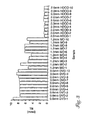
- Fig. 3 is a bar graph illustrating variation in process-induced tilt for disks having different substrate thicknesses.
- Tilt is one of the factors contributing to the overall flatness characteristic of a disk, i.e., the conformance of the beam-incident surface of the disk to the recording plane on which the write beam is focused.
- the effects of gravity and unbalanced thermal gradients during the post-mold cooling phase can cause uneven densification of different areas of the disks, producing disk warpage and tilt.
- Tilt refers to the angular variation of the disk surface relative to a plane that is tangential with the center of the disk.
- tilt can vary across the disk radius.
- a number of disk samples having different substrate thicknesses were analyzed to determine tilt in milli-radians (mrad). The samples are represented along the horizontal axis of the graph of Fig. 3, whereas tilt in mrad is shown along the vertical axis.
- a first set of disk samples consisted of ten conventional DVD disks, each having a substrate thickness of 0.6 mm. Each DVD disk was a 4.7 gigabyte (GB) disk having a diameter of 120 mm. Such DVD disks are commercially available from Imation Enterprises Corp., Oakdale, Minnesota, U.S.A.
- a second set of disk samples consisted often conventional MO disks, each having a substrate thickness of 1.2 mm. Each MO disk was a 1.3 GB disk having a diameter of 130 mm. Such MO disks are also commercially available from Imation Enterprises Corp., Oakdale, Minnesota, U.S.A.
- the third set of disk samples consisted of ten specially prepared MO disks, each having a substrate thickness of approximately 2 mm in accordance with an embodiment in the present invention.
- Each of the specially prepared MO disks had a diameter of 130 mm, and conceivably could be used with near-field recording techniques to achieve data storage densities on the order of 10 to 20 GB.
- the substrate for each of the specially prepared MO disks was molded in manner similar to that used for conventional optical disks. In particular, each substrate was molded in a mid-sized 30-100 ton injection molding press that has tooling to make a single substrate per cycle.
- the MO disks having a substrate thickness of approximately 2 mm produced significantly improved tilt characteristics.
- Tilt was measured as the maximum tilt over a sampling of radial and angular positions along the disk.
- the tilt measurement was obtained by using a laser-scanned sensor array that logged vertical displacement of the disk surface for a single rotation of the disk. By radially translating the scanner and sensor array, tilt at a full range of radii was mapped.
- the disk can be described by a function f(r, ⁇ ), where r is disk radius and ⁇ is angular position.
- Axial displacement was defined as the maximum absolute value of z or maximum deviation of the disk surface from the testing datum over the entire surface.
- Axial runout is the largest circumferential peak-to-peak value of z, i.e., max(z) - min(z) on a particular radius, found among all radii tested.
- Tilt is defined as a vector quantity, T, of the first derivative of the function that describes the disk surface, and includes a radial and tangential component. With this background, tilt provides a useful indication of overall disk flatness.
- the "thick-substrate" MO disks of the present invention produced maximum tilt on the order of 1 to 1.5 mrad.
- the reduced tilt produced in the disks having a substrate with a thickness of approximately 2 mm is one significant factor in providing improved flatness. Specifically, with lesser tilt, the surface of disk 10 better conforms to the recording plane on which the evanescently coupled beam is focused. In other words, the flatter disk surface contributes to a more consistent air gap thickness between the recording head and the surface of the disk. The air gap thickness determines the focal plane of the beam, and the amount of radiation transmitted by evanescent coupling.
- the write beam can more consistently resolve domains of increasingly smaller size. This feature is particularly useful for the aggressive spatial resolution requirements of near-field recording.
- a storage density requirement of approximately 20 GB will require a spatial resolution of approximately .0525 square microns. Accordingly, elimination of substantial air gap-induced focusing error is a critical performance factor.
- the degree of warpage can be characterized in terms of the difference between maximum and minimum tilt over the disk. In light of the significantly reduced maximum tilt measurement obtained from the specially prepared disks, as shown in Fig. 3, it is reasonable to characterize such disks as also exhibiting significantly reduced warpage.
- Fig. 4 is a graph illustrating variation in deflection for disks having different substrate thicknesses.
- Deflection is another significant factor in the overall flatness characteristic of a disk.
- the disk can be susceptible to deflection in response to forces encountered during drive operation. Such forces may result, for example, from inadvertent contact of the head with the disk surface or vibration induced by rotation of the disk. Head crashes can result, in particular, from the application of shock loads when the disk and drive system are bumped or dropped. Also, for flight during operation, the head exerts pressure against the air bearing This bearing pressure is transferred to the disk, and can cause disk deflection. Deflection generally varies across the surface area of the disk. In particular, deflection during use can be more pronounced at the outer diameter of the disk.
- the disk is held in a relatively fixed manner by a clutch mechanism associated with the drive. This disk is rotated by a spindle motor associated with the clutch mechanism.
- the radii of the disk plane form beam members relative to the fixed center of the disk. Each beam member undergoes greater deflection at the outer diameter than at the inner diameter of the disk. Thus, deviation of the disk surface from the recording plane can progressively increase from the inner diameter outward. As a result, the disk surface may not conform closely to the recording plane as it is rotated.
- the graph of Fig. 4 shows deflection data for several actual disks and substrates, as well as disks and substrates represented by finite element modeling. Specifically, with reference to Fig. 4, deflection data was obtained for the following sets of samples: sample set 1 - bare (uncoated) polycarbonate substrates having thicknesses ranging from approximately 1.24 to 1.52 mm; sample set 2 - coated (with recording layer, reflector, and dielectrics) polycarbonate substrates having thicknesses ranging from approximately 1.24 to 1.52 mm; and sample set 5 - bare (uncoated) polycarbonate substrates having thicknesses ranging from approximately 1.95 to 2.1 mm.
- sample sets 1, 2, and 5 were formed from high-flow, CD grade polycarbonate obtained from Mitsubishi Gas & Chemical Co. Deflection data was also modeled for the following sets of samples analyzed by finite element modeling: sample set 3 - bare (uncoated) polycarbonate substrates having thicknesses ranging from approximately 1.2 to 1.8 mm; and sample set 4 - coated (with recording layer, reflector, and dielectrics) polycarbonate substrates having thicknesses ranging from approximately 1.2 to 1.8 mm.
- the deflection data was represented as axial displacement in microns (Tm) relative to an initial, unloaded position.
- Tm axial displacement in microns
- each sample was loaded with a force of approximately 5 grams force (gf) at a radius from disk center of approximately 60 mm.
- the loading force is approximately equivalent to the air bearing forces expected to be exerted against the disk during operation in an air-incident, near-field recording application.
- Displacement of the sample at the 60 mm radius was then measured from its initial, unloaded position to the loaded position. This disk was not rotated during measurement. However, this static measurement is believed to provide a reasonable analog to the measurements that would be obtained during rotation.
- This displacement measurement provided an indication of relative deflection of each sample.
- the displacement data suggest a rapid decrease in disk deflection as substrate thickness is increased from approximately 1.2 mm to approximately 2.1 mm.
- a bare polycarbonate disk having a thickness of approximately 1.24 mm was observed to produce displacement of approximately 62 microns.
- a bare polycarbonate disk having a thickness of approximately 2.0 mm was observed to produce a displacement of approximately 28 microns.
- a disk having a thicker substrate can provide a clear advantage in resisting operationally-induced deflection in the drive.
- This resistance to deflection, or "stiffness,” is critical in ensuring consistent conformance of the incident surface of the disk to the recording plane.
- the deflection data also support the theoretical case for a disk substrate of increased thickness. Specifically, according to principles of mechanics, stiffness of a beam member is proportional to the elastic modulus of the material and the width of the beam. Stiffness is also a function, however, of the cube of the thickness. Thus, substrate thickness is the most powerful factor in controlling deflection.
- this characteristic of a thicker substrate is exploited to improve the flatness characteristic of the disk, and ultimately contribute to increased spatial density for recording.
- greater disk stiffness improves the consistency of air gap thickness across the surface of the disk. More consistent air gap thickness enhances the ability of the drive to focus on increasingly smaller domains on the disk.
- increased substrate thickness is generally desirable from a disk performance standpoint, it may be constrained by certain size, weight, and fabrication process considerations. Specifically, significantly increased substrate thickness can lead to a disk having excessive size and weight. Excessive size and weight can undermine interests in portability and ergonomics. Also, excessive size and weight can increase the torque, power consumption, and space requirements of the drive. In particular, excessive weight results in a disk having greater inertia and momentum, slowing spin-up and spin-down times and increasing access time by the drive. Further, greater substrate thickness can drive up the cost of materials used in the fabrication process, as well as the process time necessary for disk fabrication. With a polycarbonate or other plastic substrate, for example, the substrate is molded and allowed to cool. With increased thicknesses, the post-mold cooling process may take longer.
- Fig. 5 is a graph illustrating variation in cooling time for disks molded with different substrate thicknesses.
- Fig. 5 shows simple finite-difference results for freezing time for the midline of a disk where one-dimensional (out-of-plane) conduction dominates.
- T temperature in Kelvins
- t time
- z thickness dimension
- ⁇ the coefficient of thermal diffusivity.
- This equation is first order in time and second order in the spatial direction. Consequently, a change in substrate thickness will require an increase in post-mold cooling time that is proportional to the square of the thickness change.
- Fig. 5 shows simple finite-difference results for freezing time for the midline of a disk where one-dimensional (out-of-
- the equations are solved for conditions appropriate for polycarbonate injected into a mold at 340 degrees C, and held in contact with the metal mold surfaces at 80, 100, and 120 degrees C.
- disk substrate thicknesses on the order of 2 mm are expected to cool to solid state in less than twenty seconds.
- cooling time exceeds twenty seconds and increases at a greater rate with increased thickness.
- the key conclusion to be drawn from the data in Fig. 5 is that the required cooling time rises considerably as the substrate thickness is increased above 2.5 mm. Of course, this increased cooling time can reduce fabrication process throughput, possibly requiring additional mold stations and associated capital expenditures for desired production levels.
- the limits for substrate thickness are generally performance-based on the lower end and process-based on the upper end.
- the upper end is also influenced by the cost, size, and weight of the disk and drive.
- a balance is necessary.
- the substrate have a thickness of greater than 1.5 mm to facilitate adequate stiffness to limit deflection and vibration problems.
- a substrate having a thickness that is greater than 1.5 mm is also desirable to avoid significant warpage and tilt.
- the thickness of the substrate be less than or equal to approximately 2.5 mm.
- this balance can be achieved such that the substrate thickness is greater than or equal to approximately 1.8 mm and less than or equal to approximately 2.2 mm.
- the substrate thickness is greater than or equal to approximately 1.8 mm and less than or equal to approximately 2.2 mm.
- the substrate has a thickness of greater than or equal to approximately 1.9 mm and less than or equal to approximately 2.1 mm, and may have a thickness of approxim 2 mm.
- This thickness range has been observed to be particularly advantageous for a disk having a diameter in the range of approximately 120 to 135 mm. Given maximum disk and drive size limitations and storage density requirements, this disk diameter range appears most feasible for presently contemplated near field recording applications.
Description
- The present invention relates to rewritable optical data storage media including magneto-optic disks useful in near-field, air-incident recording applications.
- In magneto-optic recording, data is represented as a magnetized domain on a magnetizable recording medium such as a disk. Each domain is a stable magnetizable data site representative of a data bit. Data is written to the medium by applying a focused beam of high intensity light in the presence of a magnetic field. The disk typically includes a substrate, a magneto-optic recording layer, a reflective layer, and two or more dielectric layers.
- In substrate-incident recording, the beam passes through the substrate before it reaches the recording layer. The reflective layer in a substrate-incident recording medium is formed on a side of the recording layer opposite the substrate. The reflective layer reflects the beam back to the recording layer, increasing overall exposure and absorption.
- In near-field, air-incident recording, the beam does not pass through the substrate. Instead, the beam is incident on the recording layer from a side of the disk opposite the substrate. In an air-incident recording medium, the reflective layer is formed adjacent the substrate. A solid immersion lens (SIL) can be used to transmit the beam across an extremely thin air gap, and through the top of the recording medium to the recording layer. The SIL can be integrated with a flying magnetic head assembly. The air gap forms a bearing over which the flying head rides during operation. For near-field recording, the thickness of the air gap is less than one wavelength of the recording beam. Transmission of the beam is accomplished by a technique known as evanescent coupling.
- For either substrate-incident or air-incident recording, the recording beam heats a localized area of the recording medium above its Curie temperature to form a magnetizable domain. The domain is allowed to cool in the presence of a magnetic field. The magnetic field overcomes the demagnetizing field of the perpendicular anisotropy recording medium, causing the localized domain to acquire a particular magnetization. The direction of the magnetic field and the resulting magnetization determine the data represented at the domain.
- With beam modulation recording techniques, the magnetic field is maintained in a given direction for a period of time as the beam power is selectively modulated across the recording medium to achieve desired magnetizations at particular domains. According to magnetic field modulation (MFM) recording techniques, the beam is continuously scanned across the recording medium while the magnetic field is selectively modulated to achieve desired magnetization. Alternatively, the beam can be pulsed at a high frequency in coordination with modulation of the magnetic field.
- To read the recorded data, the drive applies a lower intensity, plane-polarized read beam to the recording medium. Upon transmission through and/or reflection from the recording medium, the plane-polarized read beam experiences a Kerr rotation in polarization. The Kerr angle of rotation varies as a function of the magnetization of the localized area. An optical detector receives the read beam and translates the Kerr rotation angle into an appropriate bit value.
- The amount of data storage capacity for a given magneto-optic disk depends on the spatial density of domains on the disk and the effective recording surface area of the disk. Greater spatial density results in more data per unit surface area. Greater recording surface area naturally results in greater storage capacity for a given spatial density. Recording surface area is limited, however, by disk size. Disk size has been limited in part by drive footprint requirements. Spatial density is limited primarily by the spot size of the drive laser. In other words, spatial density is a function of the ability of the drive to direct a beam to increasingly smaller domains in a consistent manner. Near-field, air-incident recording, in particular, has the potential to produce extremely small spot sizes using evanescent coupling and the resultant high numerical aperture, thereby providing increased spatial density and data storage capacity.
-
EP 0 588 647 describes a substrate-incident magneto-optical recording medium having different layers including a substrate layer.EP 0 588 647 relates to the roughness of the surface of a protective layer. The thickness of the substrate layer is disclosed as being in the range of 0.3 to 5 mm, and in particular in the range of 0.8 to 1.5 mm in order that any dust adhering to the substrate surface will not interfere with the laser beam. -
EP 0 399 532 and EP 0 541 376 disclose the types of substrate-incident optical recording media whereby it is disclosed that the thickness of the substrate is not critical as long as it is in the range 0.5 to 5.0 mm and especially 1.0 to 2.0 mm. Additionally, US 4 741 967 describes a glass and an acrylic substrate having a thickness of 1.1 mm and 1.2 mm, respectively, and an aluminium substrate having a thickness of 1.5 mm. - EP-A-0 613 127 which is considered to represent the closest prior art discloses an air-incident magneto-optic disk having a substrate being 1.2 µm thick.
- The present invention is directed to a rewritable air-incident optical data storage disk having a substrate with an increased thickness that is greater than 1.5 mm and less than or equal to 2.5 mm. The increased thickness of the substrate enhances the flatness of the recording disk relative to a recording plane. In particular, the increased thickness reduces process-induced surface variations such as warpage and tilt, and provides the disk with increased stiffness to resist deflection during use. The enhanced flatness enables data to be recorded on the disk in a consistent manner with greater spatial densities using techniques such as near-field, air-incident recording. The resulting disk thereby yields greater spatial density and data storage capacity.
- Flatness refers to the ability of the incident surface of the disk to maintain a substantially constant position relative to a recording plane on which the drive laser beam is focused. The "incident" surface refers to the surface of the disk through which the beam enters the disk. Deviation of the disk surface from the recording plane can impact the ability of the drive laser to focus on individual domains, particularly for higher spatial densities. This deviation is compounded by the fact that the disk is constantly spinning during use in a drive. In near-field applications, for example, it is expected that drives may rotate a disk at speeds on the order of 2400 to 3600 revolutions per minute (rpm). Consequently, the portion of the disk to which the recording head is directed is constantly and rapidly changing.
- For near-field, air-incident recording, the size and focal plane of a recording spot is determined primarily by the thickness of the air bearing that separates the recording head and the disk surface. If the position of the disk surface is not uniform, the air bearing thickness can vary. Variation in the air bearing thickness can result in varying focus and spot size across the disk. In particular, the thickness of the air gap determines the amount of radiation received by the recording layer via evanescent coupling. Significant variation in spot size and focus can undermine the ability of the laser to consistently address extremely small domains. Also, excessive surface nonuniformity in the disk can cause acute changes in air bearing thickness for successive domains and resultant loss of tracking. In extreme cases, head crashes, i.e., physical contact of the head with the disk, can result. Thus, unacceptable flatness can lead to disk drive failure.
- The surface of the disk can deviate from the recording plane for a number of reasons. The disk fabrication process, for example, can produce warpage and tilt in the disk. With thinner substrates, in particular, the effects of gravity and thermal gradients during the post-mold cooling phase can cause uneven densification and unbalanced thermal stresses at different areas of the disks. For example, portions of the disk closest to the mold surface will cool more quickly. The result is disk warpage and tilt.
- According to its ordinary meaning, warpage refers to a curvature of the surface of the disk. For a warped disk, tilt can vary with both radial and angular position. Tilt refers to variation of the disk surface flatness relative to an ideal disk plane, and is represented by the following equation:
- In addition to the static variations caused by fabrication, disks having thinner substrates also are susceptible to deflection in response to forces encountered during drive operation. Such forces may result, for example, from inadvertent contact of the head with the disk surface or vibration induced by rotation of the disk. Head crashes can result, in particular, from the application of shock loads when the disk and drive system are bumped or dropped. Also, for flight during operation, the head exerts pressure against the air bearing. This bearing pressure is transferred to the disk, potentially causing deflection.
- Deflection generally varies across the surface area of the disk. In particular, deflection during use can be more pronounced at the outer diameter of the disk. The disk is held in a relatively fixed manner by a clutch mechanism associated with the drive. The disk is rotated by a spindle motor associated with the clutch mechanism. The radii of the disk plane form beam members relative to the fixed center of the disk Each beam member undergoes greater deflection at the outer diameter than at the inner diameter of the disk. Thus, deviation of the disk surface from the recording plane due to deflection can progressively increase from the inner diameter outward. In any event, the disk surface may not conform closely to the recording plane as it is rotated.
- Conventional spatial densities of optical disks ordinarily tolerate some degree of focusing error, and therefore are not greatly impacted by flatness variation. Also, to the extent that focusing error is a problem, conventional substrate-incident recording drives typically include closed-loop focus adjustment across the surface of the disk. At higher spatial densities, however, surface deviation can impair the ability of the drive laser to consistently write and read to and from individual domains on the disk. With newer recording techniques such as near-field, air-incident recording, a single disk can potentially bear up to 20 gigabytes (GB) of data over the area of a disk having a diameter in the range of 120 to 135 mm. In this case, the disk must be capable of providing stable magnetized domains on the order of .05 to .06 square microns per domain.
- Higher spatial densities may allow very little if any tolerance for focusing error induced by flatness variation. Moreover, the evanescent coupling technique used in near-field, air-incident recording does not allow ready focus adjustment. Rather, the air bearing thickness is the predominant factor in determining the spot size and focal plane of the beam. With significant disk warpage, tilt, and/or deflection, the air bearing thickness can vary to an undesirable degree. As a result, the near-field recording head may suffer from focusing error and/or tracking loss. Accordingly, flatness is a critical condition in a high density recording system such as a near field recording system.
- In accordance with the disk of the present invention, the increased thickness of the substrate provides significantly enhanced flatness by increasing the rigidity and weight of the disk. The increased rigidity enables the disk to effectively resist deflection during disk drive operation. The increased weight and resulting gravity of the disk also counteract forces that would otherwise cause significant warpage and tilt during fabrication. Substrate thicknesses that are greater than 1.5 millimeters (mm) provide the rigidity and weight necessary to achieve desired flatness across the surface area of the disk, i.e., from inner to outer diameter.
- Substrate thicknesses that are greater than approximately 2.5 mm provide the necessary rigidity and weight, but can increase the cost and time involved in the fabrication process. Disk and drive material cost and excessive post-mold cooling time make substrate thicknesses of less than or equal to 2.5 mm more desirable. Substrate thicknesses greater than 2.5 mm can result in a heavier disk, requiring greater power consumption and higher rated drive motors to rotate the disk. For a given motor, the heavier disk produces excessive inertia and momentum, slowing spin-up and spin-down time and increasing data access time.
- Therefore, it is desirable that the substrate have a thickness that is greater than 1.5 mm and less than or equal to approximately 2.5 mm. More particularly, for a disk having a diameter in the range of approximately 120 to 135 mm, the substrate preferably has a thickness of greater than or equal to approximately 1.8 mm and less than or equal to approximately 2.2. A substrate having a thickness of greater than or equal to approximately 1.9 and less than or equal to approximately 2.1 mm is even more desirable, with a substrate thickness of approximately 2 mm being considered optimum given the performance and manufacturing factors considered.
- As broadly embodied and described herein, the present invention provides a rewritable optical data storage disk comprising a substrate and a recording layer, wherein the substrate has a thickness of greater than and less than or equal to 2.5 mm, 1.5 mm.
- In another embodiment, the present invention provides an air-incident magneto-optic disk comprising in order a substrate, a reflective layer, a first dielectric layer, a recording layer, and a second dielectric layer, wherein the substrate has a thickness within the range of 1.5 to 2.5 mm.
- In a third embodiment, the present invention provides a system for air-incident, magneto-optic recording, the system comprising a magneto-optic disk having a substrate and a recording layer, a radiation source oriented to direct a beam of radiation to the magneto-optic recording layer from a side of the recording medium opposite the substrate, and a detector oriented to receive a reflected component of the beam of radiation and generate a data signal based on the content of the beam of radiation, wherein the substrate has a thickness of greater than 1.5 mm and less than or equal to 2.5 mm.
In a fourth embodiment, the present invention provides a system for air-incident magneto-optic recording, comprising a magneto-optic disk having in order a substrate, a reflective layer, a first dielectric layer, a recording layer and a second dielectric layer, a radiation source is oriented to direct a beam of radiation to the recording layer from a side of the disk opposite the substrate and a detector is oriented to receive a reflected component of the beam of radiation and generate a data signal based on the contact of the beam of radiation whereby, the substrate has a thickness within the range of 1.5 to 2.5 mm. - In a fifth embodiment, the present invention provides a method for making an air-incident, magneto-optic disk comprising forming a substrate having a thickness between 1.5 mm and 2.5 mm, forming a reflective layer over the substrate, forming a first dielectric layer over the reflective layer, forming a recording layer over the first dielectric layer, and forming a second dielectric layer over the recording layer.
- Other advantages, features, and embodiments will become apparent from the following detailed description and claims.
-
- Fig. 1 is a cross-sectional diagram of a magneto-optic recording disk having a substrate with increased thickness;
- Fig. 2 is a top perspective view of the magneto-optic recording disk of Fig. 1;
- Fig. 3 is a bar graph illustrating variation in process-induced tilt for disks having different substrate thicknesses;
- Fig. 4 is a graph illustrating variation in deflection for disks having different substrate thicknesses; and
- Fig. 5 is a graph illustrating variation in required cooling time for disks molded with different substrate thicknesses.
-
- Fig. 1 is a cross-sectional diagram of a rewritable optical
data storage disk 10 having asubstrate 12 with an increased thickness, in accordance with an embodiment of the present invention.Disk 10 may be, for example, a magneto-optic recording disk. In the example of Fig. 1,disk 10 is configured for air-incident recording applications and includes, in order,substrate 12, areflective layer 14, afirst dielectric layer 16, arecording layer 18, asecond dielectric layer 20, and athird dielectric layer 22. Fig. 1 is provided for purposes of illustration and is not drawn to scale.Dielectric layers encapsulate recording layer 18 and protect it against reactants.Dielectric layer 22 may be desirable to optically tunedisk 10 and is optional. Also,reflective layer 14 optionally is included for enhanced optical and thermal response. - Fig. 2 is a top perspective view of
disk 10. As shown in Fig. 2,disk 10 is circular and has aninner diameter 23 defined by acenter hole 25, and anouter diameter 27 defined by the circumference of the disk. In Fig. 2,reference numeral 29 generally designates thevarious layers substrate 12.Disk 10 can be configured for a fixed disk drive system, but preferably is removable to facilitate the use of multiple disks with a single drive and disk portability to other drives. For removable use,disk 10 may be housed in a cartridge.Center hole 25 may accommodate a hub or other mechanism forcoupling disk 10 to a clutch and spindle motor associated with a drive. The hub may extend through the cartridge. The diameter ofcircular center hole 25 may be on the order of 15 mm. -
Substrate 12, in accordance with the present invention, has a thickness of greater than 1.5 mm.Substrate 12 preferably has a thickness of greater than 1.5 mm and less than or equal to approximately 2.5 mm. More particularly,substrate 12 preferably has a thickness of greater than or equal to approximately 1.8 mm and less than or equal to approximately 2.2 mm and, more preferably, a thickness of greater than or equal to approximately 1.9 mm and less than or equal to approximately 2.1 mm. In one particular embodiment,substrate 12 may have a thickness of approximately 2 mm for optimum performance and ease of use and fabrication. The diameter ofdisk 10 preferably is greater than or equal to approximately 120 mm and less than or equal to approximately 135 mm. More preferably,disk 10 has a diameter of approximately 130 mm for desired flatness in combination with the thickness dimension ofsubstrate 12. - With a disk having a diameter of 120 mm to 135 mm, the increased thickness of
substrate 12 has been observed to provide enhanced flatness over a range of operating conditions.Substrate 12 providesdisk 10 with increased stiffness to resist deflection in response to forces encountered during drive operation. Also, the increased thickness ofsubstrate 12 allowsdisk 10 to resist warpage and tilt that otherwise could result during fabrication due to gravity and processing-induced thermal gradients. The result of the enhanced flatness afforded bysubstrate 12 is adisk 10 that yields greater spatial density and data storage capacity. In an air-incident, near field recording application, the increased thickness ofsubstrate 12 reduces deviation of the plane ofdisk 10 from an ideal recording plane on which a beam emitted by a drive head is focused. In this manner,substrate 12 enables the air gap betweendisk 10 and the head to maintain a more constant thickness for consistent focus and spot size.Substrate 12 also enables enhanced drive reliability by reducing the susceptibility ofdisk 10 to head crashes. - With further reference to Fig. 1,
disk 10 may form part of a near-field, air-incident recording system for magneto-optic data storage. Such a system may include an integratedmagnetic head assembly 24 that emits arecording beam 26. The head assembly is oriented todirect beam 26 torecording layer 18 asdisk 10 is rotated by a spindle motor at speeds on the order of 2400 to 3600 revolutions per minute. Recordingbeam 26heats disk 10 at particular domains in the presence of a magnetic field applied bymagnetic head assembly 24. The near-field recording technique makes use of evanescent coupling to directbeam 26 torecording layer 18. The beam can be transmitted, for example, by a solid immersion lens (SIL). An example of a system having a SIL for near-field, air-incident recording of magneto-optic disks is disclosed in United States Patent No. 5,125,750 to Cole et al. Themagnetic head assembly 24 can be structurally integrated along with the SIL to form a so-called "flying head." - Recording
beam 26 is air-incident in the sense that it does not pass throughsubstrate 12 to reachrecording layer 18. Rather,recording beam 26 is incident onrecording layer 18 via the air bearing that separatesdisk 10 from the flying head. The air gap is extremely thin, having a thickness that ordinarily is less than one wavelength ofrecording beam 26.Beam 26 also may pass through one or moredielectric layers recording layer 18. As also shown in Fig. 1, readout can be achieved by application ofbeam 26 torecording layer 18 at a lower intensity. Adetector 28 is oriented to receive a reflected component of the read beam.Detector 28 translates the Kerr rotation angle of the reflected component to an appropriate bit value. Thisdetector 28 also may be structurally integrated with the flying head. - The enhanced flatness of
disk 10 allows improved conformance of the surface of the disk to the recording plane. In particular, the reduced susceptibility ofdisk 10 to warpage and tilt, along with improved stiffness for resistance to deflection, allows the air gap between the flying head and the disk to remain substantially constant, at least relative to applicable system tolerances. As a result, the position ofhead assembly 24 can be readily tuned to produce a desired air gap thickness in a consistent manner. Specifically, the enhanced flatness ofdisk 10 enableshead assembly 24 to be positioned at a substantially constant distance across the entire surface plane ofdisk 10 without regard to radial position. - In an air-incident construction, the optical characteristics of
substrate 12 are largely irrelevant. Specifically, because the beam does not enterdisk 10 throughsubstrate 12, the optical properties of the substrate have no direct optical effect on performance. In contrast, substrate-incident disks typically require substrates having particular optical properties. Thus, in an air-incident disk, it is conceivable that a wider array of materials may be used to fabricatesubstrate 12. Also, such materials could be less expensive than higher grade optical materials. For example,substrate 12 can be formed from a variety of materials including thermosets, thermoplastics, metal, or glass. The selected materials can be transparent or opaque. Also, such materials could be selected in part on the basis of the applicable elastic modulus of the material for enhanced rigidity relative to more typical substrate materials for optical disks. For optical recording, however, it is typically desirable to form a physical format onsubstrate 12 to facilitate optical tracking. Therefore, it may be most desirable to formsubstrate 12 from a material that can be readily replicated with a physical format in a mold. - An example of a particular material that is readily embossable is the high-flow polycarbonate typically used for CD production. Although polycarbonate in general is a very widely used engineering thermoplastic, this particular class of polycarbonate has been developed for the optical disk market. The ready availability and price of this class of polycarbonate make it attractive for use in
substrate 12. This polycarbonate material also provides a number of structural and manufacturing advantages. For example, high-flow polycarbonate has a sufficiently low viscosity to fill the mold without forming flow marks often associated with injection molded products. With an elastic modulus on the order of 345,000 pounds per square inch (psi), this class of polycarbonate is not generally among the stiffest of engineering thermoplastics, but is rigid enough to providedisk 10 with the desired flatness characteristic for substrate thicknesses contemplated in accordance with the present invention. In addition to sufficient rigidity, water uptake in high-flow polycarbonate is relatively low, avoiding significant deformation or environmental degradation problems due to water absorption. Also, this material exhibits a strain-at-failure of over 100 percent, indicating that the material is highly ductile. This characteristic is important for a nano-replicated plastic surface that will be used in an optical disk drive to guide a sub-micron sized laser spot to data ondisk 10. Given its acceptable performance over an array of requirements, the high-flow polycarbonate typically used for optical disk substrates provides a suitable material for fabrication ofsubstrate 12. -
Substrate 12 preferably is formed as a single, integrally formed piece, but could be constructed from two or more layers bonded together by, for example, adhesive bonding or lamination. For example, two polycarbonate substrates produced from conventional 1.2 mm MO substrate molds could be bonded together to provide a 2.4 mm substrate. To reduce the time and complexity of fabrication, however, such a polycarbonate substrate preferably is integrally formed from a single mold as a single, non-layered substrate. The other layers 14, 16, 18, 20, 22 can then be formed over the resultingsubstrate 12. - Recording
layer 18 may comprise a rare earth transition metal alloy such as FeTbCo or FeTbCoTa.Dielectric layers dielectric layers recording layer 18, whereasdielectric layer 22 may comprise silicon nitride for desired optical response. Finally,reflective layer 14 may comprise a highly reflective metal such as aluminum chrome alloy. Such a material provides both effective reflectivity and thermal conductivity. - For example,
reflective layer 14 may be formed from a layer of aluminum chrome alloy (4 weight % chromium in aluminum) having a thickness in a range of less than or equal to approximately 130 nm and greater than or equal to approximately 20 nm, and preferably less than or equal to approximately 60 nm and greater than or equal to approximately 30 nm. The thickness ofrecording layer 18 preferably is less than or equal to approximately 15 nm. In particular, the thickness ofrecording layer 18 may be in a range of less than or equal to approximately 15 nm and greater than or equal to approximately 6 nm, and preferably is in a range of less than or equal to approximately 12 nm and greater than or equal to approximately 8 nm. Recordinglayer 18, in this exemplary embodiment, may be formed from an FeTbCoTa material. In particular,recording layer 18 may having a composition, in atomic weight, of approximately 67%Fe, 23.5% Tb, 8.0% Co, and 1.5% Ta. - First
dielectric layer 16 may have a thickness in a range of less than or equal to approximately 60 nm and greater than or equal to approximately 5 nm, and preferably is in a range of less than or equal to approximately 30 nm and greater than or equal to approximately 5 nm.Second dielectric layer 20 may have a thickness in a range of less than or equal to approximately 30 nm and greater than or equal to approximately 5 nm, and preferably is greater than or equal to approximately 20 nm. In this example, first and second dielectric layers 16, 20 may be formed from a silicon carbide-graphite material marketed under the tradename Hexoloy SG and commercially available from Carborundum, Inc., Amherst, New York, U.S.A. The composition of the "Hexoloy SG" silicon carbide compound has a spectrum indicating the presence of carbon, boron, silicon, nitrogen, and oxygen in detectable concentrations. Using the peak intensities and standard sensitivity factors known in the art, the atomic concentration of this silicon carbide (SiCx) dielectric is estimated as Si(35%)C(51%)B(7%)N(5%)O(2%) which yields a value of x = 0.51/0.35 = 1.47.Third dielectric layer 22 may have a thickness in a range of less than or equal to approximately 200 nm and greater than or equal to approximately 5 nm, and preferably less than or equal to approximately 50 nm and greater than or equal to approximately 20 nm.Third dielectric layer 22 may be formed from a silicon nitride material. In this example, the silicon nitride may be Si3N4. - According to this embodiment,
disk 10 incorporates asubstrate 12 having a thickness in the range of 1.5 to 2.5 mm, as described herein, while also incorporating an extremely thin MO recording layer on the order of 6 to 15 nm in thickness. The combination of theses features provides adisk 10 having both enhanced flatness characteristics and a reduced demagnetizing field threshold. The flatness characteristic is particularly applicable to disk diameters in the range of greater than or equal to approximately 120 mm and less than or equal to approximately 135 mm. The reduced demagnetizing field threshold is useful with recording techniques, such as magnetic field modulation, that use lower magnetic fields. A disk constructed with the above materials and dimensions has been observed as capable of providing stable magnetized domains on the order of .0525 square microns per domain. -
Disk 10 preferably is constructed for air-incident recording.Disk 10 could be adapted for substrate-incident recording, however, by selecting the order in which the various layers are deposited. In particular, for substrate-incident recording,disk 10 could include, in order,substrate 12, a first dielectric layer, a recording layer, a second dielectric layer, and a reflective layer. Such a substrate-incident disk would benefit from the enhanced flatness afforded by the thickness ofsubstrate 12. At the same time, however, the increased thickness ofsubstrate 12 could cause beam focusing and attenuation problems for existing laser diode sources. - Fig. 3 is a bar graph illustrating variation in process-induced tilt for disks having different substrate thicknesses. Tilt is one of the factors contributing to the overall flatness characteristic of a disk, i.e., the conformance of the beam-incident surface of the disk to the recording plane on which the write beam is focused. The effects of gravity and unbalanced thermal gradients during the post-mold cooling phase can cause uneven densification of different areas of the disks, producing disk warpage and tilt. Tilt refers to the angular variation of the disk surface relative to a plane that is tangential with the center of the disk. Thus, for a warped disk, tilt can vary across the disk radius. As shown in Fig. 3, a number of disk samples having different substrate thicknesses were analyzed to determine tilt in milli-radians (mrad). The samples are represented along the horizontal axis of the graph of Fig. 3, whereas tilt in mrad is shown along the vertical axis.
- As indicated in the graph of Fig. 3, a first set of disk samples consisted of ten conventional DVD disks, each having a substrate thickness of 0.6 mm. Each DVD disk was a 4.7 gigabyte (GB) disk having a diameter of 120 mm. Such DVD disks are commercially available from Imation Enterprises Corp., Oakdale, Minnesota, U.S.A. A second set of disk samples consisted often conventional MO disks, each having a substrate thickness of 1.2 mm. Each MO disk was a 1.3 GB disk having a diameter of 130 mm. Such MO disks are also commercially available from Imation Enterprises Corp., Oakdale, Minnesota, U.S.A. Finally, the third set of disk samples consisted of ten specially prepared MO disks, each having a substrate thickness of approximately 2 mm in accordance with an embodiment in the present invention. Each of the specially prepared MO disks had a diameter of 130 mm, and conceivably could be used with near-field recording techniques to achieve data storage densities on the order of 10 to 20 GB. The substrate for each of the specially prepared MO disks was molded in manner similar to that used for conventional optical disks. In particular, each substrate was molded in a mid-sized 30-100 ton injection molding press that has tooling to make a single substrate per cycle.
- With reference to Fig. 3, the MO disks having a substrate thickness of approximately 2 mm produced significantly improved tilt characteristics. Tilt was measured as the maximum tilt over a sampling of radial and angular positions along the disk. The tilt measurement was obtained by using a laser-scanned sensor array that logged vertical displacement of the disk surface for a single rotation of the disk. By radially translating the scanner and sensor array, tilt at a full range of radii was mapped. As a result, the disk can be described by a function f(r,), where r is disk radius and is angular position. Axial displacement was defined as the maximum absolute value of z or maximum deviation of the disk surface from the testing datum over the entire surface. Axial runout is the largest circumferential peak-to-peak value of z, i.e., max(z) - min(z) on a particular radius, found among all radii tested. Tilt is defined as a vector quantity, T, of the first derivative of the function that describes the disk surface, and includes a radial and tangential component. With this background, tilt provides a useful indication of overall disk flatness.
- As shown in Fig. 3, whereas the DVD disks and MO disks produced maximum tilt ranging from approximately 5 to 9.5 mrad, the "thick-substrate" MO disks of the present invention produced maximum tilt on the order of 1 to 1.5 mrad. The reduced tilt produced in the disks having a substrate with a thickness of approximately 2 mm is one significant factor in providing improved flatness. Specifically, with lesser tilt, the surface of
disk 10 better conforms to the recording plane on which the evanescently coupled beam is focused. In other words, the flatter disk surface contributes to a more consistent air gap thickness between the recording head and the surface of the disk. The air gap thickness determines the focal plane of the beam, and the amount of radiation transmitted by evanescent coupling. By reducing variation in air gap thickness, the write beam can more consistently resolve domains of increasingly smaller size. This feature is particularly useful for the aggressive spatial resolution requirements of near-field recording. With a 130 mm disk, for example, a storage density requirement of approximately 20 GB will require a spatial resolution of approximately .0525 square microns. Accordingly, elimination of substantial air gap-induced focusing error is a critical performance factor. Following measurement of tilt, the degree of warpage can be characterized in terms of the difference between maximum and minimum tilt over the disk. In light of the significantly reduced maximum tilt measurement obtained from the specially prepared disks, as shown in Fig. 3, it is reasonable to characterize such disks as also exhibiting significantly reduced warpage. - Fig. 4 is a graph illustrating variation in deflection for disks having different substrate thicknesses. Deflection is another significant factor in the overall flatness characteristic of a disk. In particular, the disk can be susceptible to deflection in response to forces encountered during drive operation. Such forces may result, for example, from inadvertent contact of the head with the disk surface or vibration induced by rotation of the disk. Head crashes can result, in particular, from the application of shock loads when the disk and drive system are bumped or dropped. Also, for flight during operation, the head exerts pressure against the air bearing This bearing pressure is transferred to the disk, and can cause disk deflection. Deflection generally varies across the surface area of the disk. In particular, deflection during use can be more pronounced at the outer diameter of the disk. The disk is held in a relatively fixed manner by a clutch mechanism associated with the drive. This disk is rotated by a spindle motor associated with the clutch mechanism. The radii of the disk plane form beam members relative to the fixed center of the disk. Each beam member undergoes greater deflection at the outer diameter than at the inner diameter of the disk. Thus, deviation of the disk surface from the recording plane can progressively increase from the inner diameter outward. As a result, the disk surface may not conform closely to the recording plane as it is rotated.
- The graph of Fig. 4 shows deflection data for several actual disks and substrates, as well as disks and substrates represented by finite element modeling. Specifically, with reference to Fig. 4, deflection data was obtained for the following sets of samples: sample set 1 - bare (uncoated) polycarbonate substrates having thicknesses ranging from approximately 1.24 to 1.52 mm; sample set 2 - coated (with recording layer, reflector, and dielectrics) polycarbonate substrates having thicknesses ranging from approximately 1.24 to 1.52 mm; and sample set 5 - bare (uncoated) polycarbonate substrates having thicknesses ranging from approximately 1.95 to 2.1 mm. The polycarbonate substrates in sample sets 1, 2, and 5 were formed from high-flow, CD grade polycarbonate obtained from Mitsubishi Gas & Chemical Co. Deflection data was also modeled for the following sets of samples analyzed by finite element modeling: sample set 3 - bare (uncoated) polycarbonate substrates having thicknesses ranging from approximately 1.2 to 1.8 mm; and sample set 4 - coated (with recording layer, reflector, and dielectrics) polycarbonate substrates having thicknesses ranging from approximately 1.2 to 1.8 mm.
- Each sample, actual and modeled, had a radius of 130 mm. The deflection data was represented as axial displacement in microns (Tm) relative to an initial, unloaded position. To obtain the deflection data, each sample was loaded with a force of approximately 5 grams force (gf) at a radius from disk center of approximately 60 mm. The loading force is approximately equivalent to the air bearing forces expected to be exerted against the disk during operation in an air-incident, near-field recording application. Displacement of the sample at the 60 mm radius was then measured from its initial, unloaded position to the loaded position. This disk was not rotated during measurement. However, this static measurement is believed to provide a reasonable analog to the measurements that would be obtained during rotation. This displacement measurement provided an indication of relative deflection of each sample. As illustrated by the graph of Fig. 4, the displacement data suggest a rapid decrease in disk deflection as substrate thickness is increased from approximately 1.2 mm to approximately 2.1 mm. In particular, a bare polycarbonate disk having a thickness of approximately 1.24 mm was observed to produce displacement of approximately 62 microns. In contrast, a bare polycarbonate disk having a thickness of approximately 2.0 mm was observed to produce a displacement of approximately 28 microns.
- Based on the data represented in the graph of Fig. 4, it is evident that a disk having a thicker substrate can provide a clear advantage in resisting operationally-induced deflection in the drive. This resistance to deflection, or "stiffness," is critical in ensuring consistent conformance of the incident surface of the disk to the recording plane. The deflection data also support the theoretical case for a disk substrate of increased thickness. Specifically, according to principles of mechanics, stiffness of a beam member is proportional to the elastic modulus of the material and the width of the beam. Stiffness is also a function, however, of the cube of the thickness. Thus, substrate thickness is the most powerful factor in controlling deflection. In accordance with the present invention, this characteristic of a thicker substrate is exploited to improve the flatness characteristic of the disk, and ultimately contribute to increased spatial density for recording. In particular, greater disk stiffness improves the consistency of air gap thickness across the surface of the disk. More consistent air gap thickness enhances the ability of the drive to focus on increasingly smaller domains on the disk.
- Although increased substrate thickness is generally desirable from a disk performance standpoint, it may be constrained by certain size, weight, and fabrication process considerations. Specifically, significantly increased substrate thickness can lead to a disk having excessive size and weight. Excessive size and weight can undermine interests in portability and ergonomics. Also, excessive size and weight can increase the torque, power consumption, and space requirements of the drive. In particular, excessive weight results in a disk having greater inertia and momentum, slowing spin-up and spin-down times and increasing access time by the drive. Further, greater substrate thickness can drive up the cost of materials used in the fabrication process, as well as the process time necessary for disk fabrication. With a polycarbonate or other plastic substrate, for example, the substrate is molded and allowed to cool. With increased thicknesses, the post-mold cooling process may take longer.
- Fig. 5 is a graph illustrating variation in cooling time for disks molded with different substrate thicknesses. Fig. 5 shows simple finite-difference results for freezing time for the midline of a disk where one-dimensional (out-of-plane) conduction dominates. The governing equation for one-dimensional transient heat conduction is as follows:
- In view of the tilt and deflection data of Figs. 3 and 4 and the process data of Fig. 5, the limits for substrate thickness are generally performance-based on the lower end and process-based on the upper end. The upper end is also influenced by the cost, size, and weight of the disk and drive. Thus, a balance is necessary. In accordance with the present invention, it is desirable that the substrate have a thickness of greater than 1.5 mm to facilitate adequate stiffness to limit deflection and vibration problems. A substrate having a thickness that is greater than 1.5 mm is also desirable to avoid significant warpage and tilt. To allow feasible processing time, as well as reasonable cost, size and weight of the disk and drive, however, it is desirable that the thickness of the substrate be less than or equal to approximately 2.5 mm. In a preferred embodiment, this balance can be achieved such that the substrate thickness is greater than or equal to approximately 1.8 mm and less than or equal to approximately 2.2 mm. With a substrate thickness in this preferred range, satisfactory disk flatness has been observed without producing excessive processing time or significantly driving up the material cost, size, and weight of the disk and drive. More preferably, the substrate has a thickness of greater than or equal to approximately 1.9 mm and less than or equal to approximately 2.1 mm, and may have a thickness of
approxim 2 mm. This thickness range has been observed to be particularly advantageous for a disk having a diameter in the range of approximately 120 to 135 mm. Given maximum disk and drive size limitations and storage density requirements, this disk diameter range appears most feasible for presently contemplated near field recording applications.
Claims (20)
- A rewritable air-incident optical data storage disk (10) comprising a substrate (12) and a recording layer (18),
characterized in that
the substrate has a thickness greater than 1.5 mm and less than or equal to 2.5 mm. - An air-incident, magneto-optic disk comprising in ordercharacterized in thata substrate (12),a reflective layer (14),a first dielectric layer (16),a recording layer (18), anda second dielectric layer (20),
the substrate (12) has a thickness within the range of 1.5 to 2.5 mm. - A system for air-incident, magneto-optic recording, the system comprising a magneto-optic disk (10) having a substrate (12) and a recording layer (18), a radiation source (24) oriented to direct a beam of radiation (26) to the recording layer from a side of the disk opposite the substrate, and a detector (28) oriented to receive a reflected component of the beam of radiation and generate a data signal based on the contact of the beam of radiation,
characterized in that
the substrate has a thickness greater than 1.5 mm and less than or equal to 2.5 mm. - A system for air-incident magneto-optic recording, the system comprising a magneto-optic disk (10) having in order a substrate (12), a reflective layer (14), a first dielectric layer (16), a recording layer (18) and a second dielectric layer (10), a radiation source (24) oriented to direct a beam of radiation (26) to the recording layer from a side of the disk opposite the substrate, and a detector (28) oriented to receive a reflected component of the beam of radiation and generate a date signal based on the contact of the beam of radiation,
characterized in that
the substrate (12) has a thickness within the range of 1.5 to 2.5 mm. - The disk of claim 1, wherein the disk is a magneto-optic disk and the recording layer comprises a magneto-optic recording material.
- The disk of any of claims 1 to 4, wherein the thickness of the substrate is greater than or equal to approximately 1.8 mm and less than or equal to approximately 2.2 mm.
- The disk of any of claims 1 to 4, wherein the thickness of the substrate is greater than or equal to approximately 1.9 mm and less than or equal to approximately 2.1 mm.
- The disk of any of claims 1 to 4, wherein the thickness of the substrate is approximately 2 mm.
- The disk of any of claims 1 to 8, wherein the disk has a diameter of greater than or equal to approximately 120 mm and less than or equal to approximately 135 mm.
- The disk of claim 9, wherein the disk has a diameter of approximately 130 mm.
- The disk of any of claims 1 to 10, wherein the substrate comprises a material selected from the group consisting of thermoset, thermoplastic, glass, and metal.
- The disk of any of claims 1 to 10, wherein the substrate comprises polycarbonate material.
- The disk of any of claims 1 to 10, wherein the disk is capable of forming stable magnetizable domains having dimensions of less than or equal to approximately 0.06 µm2.
- The disk of any of claims 1 to 10, wherein the substrate and recording layer include a central hole (25) having a diameter of approximately 15 mm.
- The system of any of claims 3 and 4, wherein the disk rotates at a speed of greater than or equal to approximately 2400 revolutions per minute.
- The system of any of claims 3 and 4, further comprising a solid immersion lens separated from the disk by a distance of less than one wavelength of the beam of radiation, the solid immersion lens transmitting the beam of radiation to the disk by evanescent coupling.
- A method for making an air-incident, magneto-optic disk (10) comprising:characterized in thatforming a substrate (12),forming a reflective layer (14) over the substrate,forming a first dielectric layer (16) over the reflective layer,forming a recording layer (18) over the first dielectric layer, andforming a second dielectric layer (20) over the recording layer,
the substrate has a thickness between 1.5 and 2.5 mm. - The method of claim 17, wherein the thickness of the substrate is greater than or equal to approximately 1.8 mm and less than or equal to approximately 2.2 mm.
- The method of claim 17, wherein the thickness of the substrate is approximately 2 mm.
- The disk of any of claims 1 to 3, wherein the substrate (12) comprises a non-metal material.
Applications Claiming Priority (3)
| Application Number | Priority Date | Filing Date | Title |
|---|---|---|---|
| US09/003,580 US5972461A (en) | 1998-01-06 | 1998-01-06 | Rewritable optical data storage disk having enhanced flatness |
| US3580 | 1998-01-06 | ||
| PCT/US1998/007217 WO1999035642A1 (en) | 1998-01-06 | 1998-04-10 | Rewritable optical data storage disk having enhanced flatness |
Publications (2)
| Publication Number | Publication Date |
|---|---|
| EP1046162A1 EP1046162A1 (en) | 2000-10-25 |
| EP1046162B1 true EP1046162B1 (en) | 2003-03-05 |
Family
ID=21706553
Family Applications (1)
| Application Number | Title | Priority Date | Filing Date |
|---|---|---|---|
| EP98915466A Expired - Lifetime EP1046162B1 (en) | 1998-01-06 | 1998-04-10 | Rewritable optical data storage disk having enhanced flatness |
Country Status (6)
| Country | Link |
|---|---|
| US (2) | US5972461A (en) |
| EP (1) | EP1046162B1 (en) |
| JP (1) | JP2002501273A (en) |
| CN (1) | CN1145157C (en) |
| DE (1) | DE69811958T2 (en) |
| WO (1) | WO1999035642A1 (en) |
Cited By (1)
| Publication number | Priority date | Publication date | Assignee | Title |
|---|---|---|---|---|
| USRE46060E1 (en) | 1997-02-10 | 2016-07-05 | Genesys Telecommunications Laboratories, Inc. | In-band signaling for routing |
Families Citing this family (30)
| Publication number | Priority date | Publication date | Assignee | Title |
|---|---|---|---|---|
| US6127017A (en) * | 1997-04-30 | 2000-10-03 | Hitachi Maxell, Ltd. | Substrate for information recording disk, mold and stamper for injection molding substrate, and method for making stamper, and information recording disk |
| JPH11149664A (en) * | 1997-11-19 | 1999-06-02 | Sharp Corp | Optical disk |
| US6238763B1 (en) * | 1998-01-06 | 2001-05-29 | Imation Corp. | Rewritable optical data storage disk having enhanced flatness |
| US6324129B1 (en) * | 1998-01-08 | 2001-11-27 | Seagate Technology Llc | Near field magneto-optical head having read and write pinhole apertures |
| JPH11296904A (en) | 1998-04-03 | 1999-10-29 | Toshiba Corp | Information recording medium and manufacture of resin substrate used for the same |
| US6214430B1 (en) * | 1998-04-10 | 2001-04-10 | Lg Electronics Inc. | Disc recording medium and method of fabricating the same |
| US6545974B1 (en) * | 1998-11-18 | 2003-04-08 | Seagate Technology Llc | Disc media and methods for fabricating |
| US6381200B1 (en) * | 1998-11-18 | 2002-04-30 | Seagate Technology Llc | Flash layer overcoat for first surface magneto-optical media |
| US6335080B1 (en) | 1999-01-04 | 2002-01-01 | Seagate Technology Llc | Magnetic disk media and disk drives utilizing polymeric disk substrates |
| BR0008208A (en) | 1999-02-12 | 2002-02-19 | Gen Electric | Data storage media |
| US6816820B1 (en) * | 1999-09-24 | 2004-11-09 | Moldflow Ireland, Ltd. | Method and apparatus for modeling injection of a fluid in a mold cavity |
| US6269072B1 (en) * | 1999-10-22 | 2001-07-31 | Victor Company Of Japan, Ltd. | Optical disc |
| US6678238B1 (en) | 1999-12-29 | 2004-01-13 | Imation Corp. | Mold for manufacturing double-sided disk shaped articles for storing data |
| US6441123B1 (en) * | 2000-05-31 | 2002-08-27 | General Electric Company | Vibration damping monolithic polymers |
| JP2002117584A (en) * | 2000-10-06 | 2002-04-19 | Sony Corp | Optical recording medium and its manufacturing method |
| US6501589B1 (en) * | 2001-02-22 | 2002-12-31 | Aralight | Article comprising a metallic anti-mirror |
| US7300690B2 (en) * | 2001-03-29 | 2007-11-27 | General Electric Company | Radial tilt reduced media |
| US20020145826A1 (en) * | 2001-04-09 | 2002-10-10 | University Of Alabama | Method for the preparation of nanometer scale particle arrays and the particle arrays prepared thereby |
| US20030060552A1 (en) * | 2001-05-08 | 2003-03-27 | Balfour Kim G. | Corona resistant thermoplastic blends and methods for manufacture thereof |
| TWI238389B (en) * | 2001-11-21 | 2005-08-21 | Ind Tech Res Inst | High density micro-optical pickup head |
| CN1764917A (en) * | 2003-02-05 | 2006-04-26 | 莫尔德弗洛爱尔兰有限公司 | Apparatus and methods for performing process simulation using a hybrid model |
| AU2004217469A1 (en) * | 2003-03-03 | 2004-09-16 | Moldflow Ireland Ltd. | Apparatus and methods for predicting properties of processed material |
| JP4340459B2 (en) * | 2003-03-14 | 2009-10-07 | 株式会社 日立ディスプレイズ | Manufacturing method of display device |
| US20040268379A1 (en) * | 2003-06-30 | 2004-12-30 | Imation Corp. | Storage media volumetric factor |
| JP2007283520A (en) * | 2006-04-13 | 2007-11-01 | Mitsubishi Kagaku Media Co Ltd | Thermosensitive printing layer and optical recording medium employing thereof |
| US7910234B2 (en) * | 2006-04-28 | 2011-03-22 | Imation Corp. | Magnetic recording medium having improved durability for high density applications |
| JP5053229B2 (en) * | 2007-11-21 | 2012-10-17 | パナソニック株式会社 | GAP CONTROL DEVICE AND OPTICAL INFORMATION DEVICE |
| US8877359B2 (en) * | 2008-12-05 | 2014-11-04 | Wd Media (Singapore) Pte. Ltd. | Magnetic disk and method for manufacturing same |
| JP7029319B2 (en) * | 2018-03-13 | 2022-03-03 | マクセル株式会社 | A coating type magnetic recording medium for heat-assisted recording, a heat-assisted magnetic recording device using the same, and a heat-assisted magnetic recording method. |
| US20210090601A1 (en) * | 2019-09-25 | 2021-03-25 | Western Digital Technologies, Inc. | Magnetic recording apparatus comprising disk with reduced thickness and reduced disk flatness |
Family Cites Families (23)
| Publication number | Priority date | Publication date | Assignee | Title |
|---|---|---|---|---|
| JPS56169238A (en) * | 1980-05-28 | 1981-12-25 | Sharp Corp | Magnetooptical storage disk |
| US4741967A (en) * | 1983-06-08 | 1988-05-03 | Canon Kabushiki Kaisha | Magnetic recording medium |
| JPS60218732A (en) * | 1984-04-13 | 1985-11-01 | Toshiba Corp | Cutting-off device of arrester |
| US4664964A (en) * | 1984-04-23 | 1987-05-12 | Fuji Photo Film Co., Ltd. | Magnetic recording medium |
| JPS6169238A (en) | 1984-09-12 | 1986-04-09 | Fujitsu Ltd | Call number adding system |
| JPH06101115B2 (en) | 1985-09-30 | 1994-12-12 | 京セラ株式会社 | Zirconia magnetic disk substrate and manufacturing method thereof |
| US5158834A (en) * | 1988-02-01 | 1992-10-27 | Minnesota Mining And Manufacturing Company | Magneto optic recording medium with silicon carbide dielectric |
| JPH02254648A (en) * | 1989-03-28 | 1990-10-15 | Seiko Epson Corp | Magneto-optical disk |
| US5032470A (en) * | 1989-04-17 | 1991-07-16 | Mitsui Petrochemical Industries, Ltd. | Optical recording medium with an aluminum alloy metallic layer containing at least hafnium |
| CA2017226A1 (en) * | 1989-05-23 | 1990-11-23 | Kiyotaka Shindo | Information recording media |
| JP2549079B2 (en) * | 1989-08-31 | 1996-10-30 | ダイセル化学工業株式会社 | Composite magneto-optical recording medium |
| US5125750A (en) * | 1991-03-14 | 1992-06-30 | The Board Of Trustees Of The Leland Stanford Junior University | Optical recording system employing a solid immersion lens |
| DE4223850A1 (en) * | 1991-07-23 | 1993-01-28 | Mitsubishi Chem Ind | Improved magneto=optical recording medium - has rare-earth element transition metal element alloy recording layer and tantalum pent:oxide adhesion promoting and interference layer |
| EP0541376B1 (en) * | 1991-11-07 | 1998-06-03 | Toray Industries, Inc. | Optical recording medium |
| JPH05225609A (en) * | 1992-02-06 | 1993-09-03 | Tdk Corp | Optical disk base plate and optical disk |
| US5470627A (en) * | 1992-03-06 | 1995-11-28 | Quantum Corporation | Double-sided optical media for a disk storage device |
| US5576087A (en) * | 1992-09-18 | 1996-11-19 | Canon Kabushiki Kaisha | Magneto-optical recording medium |
| CA2127059A1 (en) * | 1993-07-02 | 1995-01-03 | Masahiko Sekiya | Magneto-optical recording medium |
| JPH07182709A (en) * | 1993-11-15 | 1995-07-21 | Minnesota Mining & Mfg Co <3M> | Magneto-optical recording medium |
| US5510163A (en) | 1994-05-18 | 1996-04-23 | National Research Council Of Canada | Optical storage media having visible logos |
| JPH08115541A (en) * | 1994-08-24 | 1996-05-07 | Hitachi Maxell Ltd | Magneto-optical recording medium |
| US5593790A (en) * | 1994-12-29 | 1997-01-14 | Imation Corp. | Interference super-resolution using two magnetic layer construction |
| JPH09180276A (en) * | 1995-12-25 | 1997-07-11 | Sharp Corp | Magneto-optical recording medium and reproducing method therefor |
-
1998
- 1998-01-06 US US09/003,580 patent/US5972461A/en not_active Expired - Fee Related
- 1998-04-10 EP EP98915466A patent/EP1046162B1/en not_active Expired - Lifetime
- 1998-04-10 WO PCT/US1998/007217 patent/WO1999035642A1/en active IP Right Grant
- 1998-04-10 DE DE69811958T patent/DE69811958T2/en not_active Expired - Fee Related
- 1998-04-10 JP JP2000527939A patent/JP2002501273A/en active Pending
- 1998-04-10 CN CNB988129620A patent/CN1145157C/en not_active Expired - Fee Related
-
1999
- 1999-07-25 US US09/360,749 patent/US6180201B1/en not_active Expired - Fee Related
Cited By (1)
| Publication number | Priority date | Publication date | Assignee | Title |
|---|---|---|---|---|
| USRE46060E1 (en) | 1997-02-10 | 2016-07-05 | Genesys Telecommunications Laboratories, Inc. | In-band signaling for routing |
Also Published As
| Publication number | Publication date |
|---|---|
| JP2002501273A (en) | 2002-01-15 |
| DE69811958D1 (en) | 2003-04-10 |
| DE69811958T2 (en) | 2003-12-18 |
| WO1999035642A1 (en) | 1999-07-15 |
| EP1046162A1 (en) | 2000-10-25 |
| US5972461A (en) | 1999-10-26 |
| US6180201B1 (en) | 2001-01-30 |
| CN1145157C (en) | 2004-04-07 |
| CN1285949A (en) | 2001-02-28 |
Similar Documents
| Publication | Publication Date | Title |
|---|---|---|
| EP1046162B1 (en) | Rewritable optical data storage disk having enhanced flatness | |
| US6238763B1 (en) | Rewritable optical data storage disk having enhanced flatness | |
| US5470627A (en) | Double-sided optical media for a disk storage device | |
| US5202880A (en) | Double-sided magneto-optical media for a multi-disk storage device | |
| US6160769A (en) | Optical recording medium and optical recording device | |
| US20100254247A1 (en) | Optical data recording medium and method for reproducing recorded data | |
| US7027385B1 (en) | Optical disk, disk substrate, and drive | |
| EP0445957A2 (en) | Magneto-optical disk and method of reproducing the same | |
| US5667887A (en) | Magneto-optical media | |
| US5593790A (en) | Interference super-resolution using two magnetic layer construction | |
| JP4419948B2 (en) | Optical recording and playback method | |
| EP1052629A1 (en) | Optical recording medium | |
| JP2622206B2 (en) | Magneto-optical recording medium | |
| KR100613797B1 (en) | Optical recording medium | |
| KR100517466B1 (en) | Disc With Heat Radiating Layer | |
| JP2003157573A (en) | Flexible optical disk and optical disk device | |
| JP2636694B2 (en) | Recording / reproducing method and recording / reproducing apparatus for magneto-optical recording medium | |
| JP2001155384A (en) | Information recording disk | |
| JP2000057648A (en) | Optical pickup and recording medium recording/ reproducing device | |
| JP2002117581A (en) | Surface readout type optical read-only medium and readout device | |
| JP2000331395A (en) | Method for recording magneto-optical disk and magneto- optical recorder | |
| JPH04176038A (en) | Magneto-optical disk | |
| JP2005093026A (en) | Optical recording medium | |
| JPH10208322A (en) | Magneto-optical recording medium | |
| JP2000149345A (en) | Method for recording magneto-optical disk and method for reproducing the disk |
Legal Events
| Date | Code | Title | Description |
|---|---|---|---|
| PUAI | Public reference made under article 153(3) epc to a published international application that has entered the european phase |
Free format text: ORIGINAL CODE: 0009012 |
|
| 17P | Request for examination filed |
Effective date: 20000621 |
|
| AK | Designated contracting states |
Kind code of ref document: A1 Designated state(s): DE GB |
|
| 17Q | First examination report despatched |
Effective date: 20010208 |
|
| GRAH | Despatch of communication of intention to grant a patent |
Free format text: ORIGINAL CODE: EPIDOS IGRA |
|
| GRAH | Despatch of communication of intention to grant a patent |
Free format text: ORIGINAL CODE: EPIDOS IGRA |
|
| GRAA | (expected) grant |
Free format text: ORIGINAL CODE: 0009210 |
|
| AK | Designated contracting states |
Designated state(s): DE GB |
|
| REG | Reference to a national code |
Ref country code: GB Ref legal event code: FG4D |
|
| REF | Corresponds to: |
Ref document number: 69811958 Country of ref document: DE Date of ref document: 20030410 Kind code of ref document: P |
|
| PGFP | Annual fee paid to national office [announced via postgrant information from national office to epo] |
Ref country code: GB Payment date: 20030612 Year of fee payment: 6 |
|
| PLBE | No opposition filed within time limit |
Free format text: ORIGINAL CODE: 0009261 |
|
| STAA | Information on the status of an ep patent application or granted ep patent |
Free format text: STATUS: NO OPPOSITION FILED WITHIN TIME LIMIT |
|
| 26N | No opposition filed |
Effective date: 20031208 |
|
| PG25 | Lapsed in a contracting state [announced via postgrant information from national office to epo] |
Ref country code: GB Free format text: LAPSE BECAUSE OF NON-PAYMENT OF DUE FEES Effective date: 20040410 |
|
| GBPC | Gb: european patent ceased through non-payment of renewal fee |
Effective date: 20040410 |
|
| PGFP | Annual fee paid to national office [announced via postgrant information from national office to epo] |
Ref country code: DE Payment date: 20060428 Year of fee payment: 9 |
|
| PG25 | Lapsed in a contracting state [announced via postgrant information from national office to epo] |
Ref country code: DE Free format text: LAPSE BECAUSE OF NON-PAYMENT OF DUE FEES Effective date: 20071101 |