EP1049320B1 - Verbindungsherstellung zwischen Computern beruhend auf der Dekodierung einer steganographisch in einem Audioobjekt eingebetteten Adresse - Google Patents
Verbindungsherstellung zwischen Computern beruhend auf der Dekodierung einer steganographisch in einem Audioobjekt eingebetteten Adresse Download PDFInfo
- Publication number
- EP1049320B1 EP1049320B1 EP00116604A EP00116604A EP1049320B1 EP 1049320 B1 EP1049320 B1 EP 1049320B1 EP 00116604 A EP00116604 A EP 00116604A EP 00116604 A EP00116604 A EP 00116604A EP 1049320 B1 EP1049320 B1 EP 1049320B1
- Authority
- EP
- European Patent Office
- Prior art keywords
- signal
- image
- noise
- bit
- data
- Prior art date
- Legal status (The legal status is an assumption and is not a legal conclusion. Google has not performed a legal analysis and makes no representation as to the accuracy of the status listed.)
- Expired - Lifetime
Links
- 230000000977 initiatory effect Effects 0.000 title claims description 5
- 238000000034 method Methods 0.000 claims abstract description 360
- 238000004891 communication Methods 0.000 claims description 21
- 238000003860 storage Methods 0.000 claims description 15
- 230000000007 visual effect Effects 0.000 claims description 12
- 238000006243 chemical reaction Methods 0.000 claims description 8
- 230000004044 response Effects 0.000 claims description 2
- 238000012545 processing Methods 0.000 abstract description 33
- 238000004458 analytical method Methods 0.000 abstract description 18
- 230000009471 action Effects 0.000 abstract description 6
- 230000001131 transforming effect Effects 0.000 abstract description 2
- 238000005516 engineering process Methods 0.000 description 120
- 230000008569 process Effects 0.000 description 119
- 239000000463 material Substances 0.000 description 53
- 239000002131 composite material Substances 0.000 description 49
- 238000013459 approach Methods 0.000 description 47
- 239000000047 product Substances 0.000 description 39
- 230000005540 biological transmission Effects 0.000 description 34
- 238000007906 compression Methods 0.000 description 34
- 230000000875 corresponding effect Effects 0.000 description 34
- 230000006870 function Effects 0.000 description 34
- 238000001514 detection method Methods 0.000 description 32
- 238000012544 monitoring process Methods 0.000 description 32
- 230000006835 compression Effects 0.000 description 30
- 230000001413 cellular effect Effects 0.000 description 29
- 230000008901 benefit Effects 0.000 description 26
- 230000008859 change Effects 0.000 description 26
- 239000013598 vector Substances 0.000 description 24
- 238000013461 design Methods 0.000 description 21
- 230000005236 sound signal Effects 0.000 description 21
- 238000009826 distribution Methods 0.000 description 18
- 238000001914 filtration Methods 0.000 description 18
- 230000006872 improvement Effects 0.000 description 16
- 239000004033 plastic Substances 0.000 description 16
- 230000000694 effects Effects 0.000 description 15
- 238000004422 calculation algorithm Methods 0.000 description 14
- 239000000243 solution Substances 0.000 description 14
- 238000012795 verification Methods 0.000 description 14
- 230000033001 locomotion Effects 0.000 description 13
- 238000005457 optimization Methods 0.000 description 13
- 238000007792 addition Methods 0.000 description 12
- 230000002829 reductive effect Effects 0.000 description 11
- 238000004519 manufacturing process Methods 0.000 description 10
- 238000013528 artificial neural network Methods 0.000 description 9
- 238000010586 diagram Methods 0.000 description 9
- 238000001228 spectrum Methods 0.000 description 9
- 238000011161 development Methods 0.000 description 8
- 230000018109 developmental process Effects 0.000 description 8
- 238000007667 floating Methods 0.000 description 8
- 230000001965 increasing effect Effects 0.000 description 8
- 238000003909 pattern recognition Methods 0.000 description 8
- 230000004075 alteration Effects 0.000 description 7
- 230000002596 correlated effect Effects 0.000 description 7
- 230000007246 mechanism Effects 0.000 description 7
- 230000004224 protection Effects 0.000 description 7
- 230000003595 spectral effect Effects 0.000 description 7
- 230000009466 transformation Effects 0.000 description 7
- 230000006837 decompression Effects 0.000 description 6
- 230000007423 decrease Effects 0.000 description 6
- 230000003287 optical effect Effects 0.000 description 6
- 230000008878 coupling Effects 0.000 description 5
- 238000010168 coupling process Methods 0.000 description 5
- 238000005859 coupling reaction Methods 0.000 description 5
- 239000012634 fragment Substances 0.000 description 5
- 238000013139 quantization Methods 0.000 description 5
- 238000005070 sampling Methods 0.000 description 5
- 238000012360 testing method Methods 0.000 description 5
- 210000004556 brain Anatomy 0.000 description 4
- 238000010367 cloning Methods 0.000 description 4
- 238000013144 data compression Methods 0.000 description 4
- 230000012010 growth Effects 0.000 description 4
- 238000003384 imaging method Methods 0.000 description 4
- 238000007373 indentation Methods 0.000 description 4
- 238000012986 modification Methods 0.000 description 4
- 230000004048 modification Effects 0.000 description 4
- 230000008520 organization Effects 0.000 description 4
- 238000000059 patterning Methods 0.000 description 4
- 238000007639 printing Methods 0.000 description 4
- 238000011160 research Methods 0.000 description 4
- 238000000926 separation method Methods 0.000 description 4
- 238000000844 transformation Methods 0.000 description 4
- 238000012952 Resampling Methods 0.000 description 3
- 230000003466 anti-cipated effect Effects 0.000 description 3
- 230000002238 attenuated effect Effects 0.000 description 3
- 230000003796 beauty Effects 0.000 description 3
- 238000004364 calculation method Methods 0.000 description 3
- 239000012141 concentrate Substances 0.000 description 3
- 238000005520 cutting process Methods 0.000 description 3
- 230000002354 daily effect Effects 0.000 description 3
- 230000003111 delayed effect Effects 0.000 description 3
- 230000003292 diminished effect Effects 0.000 description 3
- 238000002474 experimental method Methods 0.000 description 3
- 230000000873 masking effect Effects 0.000 description 3
- 238000005259 measurement Methods 0.000 description 3
- 230000003252 repetitive effect Effects 0.000 description 3
- 230000002441 reversible effect Effects 0.000 description 3
- 238000011179 visual inspection Methods 0.000 description 3
- XOJVVFBFDXDTEG-UHFFFAOYSA-N Norphytane Natural products CC(C)CCCC(C)CCCC(C)CCCC(C)C XOJVVFBFDXDTEG-UHFFFAOYSA-N 0.000 description 2
- OAICVXFJPJFONN-UHFFFAOYSA-N Phosphorus Chemical compound [P] OAICVXFJPJFONN-UHFFFAOYSA-N 0.000 description 2
- 230000003190 augmentative effect Effects 0.000 description 2
- 239000000969 carrier Substances 0.000 description 2
- 239000003086 colorant Substances 0.000 description 2
- 239000000470 constituent Substances 0.000 description 2
- 238000005336 cracking Methods 0.000 description 2
- 230000006378 damage Effects 0.000 description 2
- 239000000839 emulsion Substances 0.000 description 2
- 230000002708 enhancing effect Effects 0.000 description 2
- 238000001093 holography Methods 0.000 description 2
- 230000007774 longterm Effects 0.000 description 2
- 238000007726 management method Methods 0.000 description 2
- 238000012567 pattern recognition method Methods 0.000 description 2
- 230000008447 perception Effects 0.000 description 2
- 238000007781 pre-processing Methods 0.000 description 2
- 238000003672 processing method Methods 0.000 description 2
- 230000000246 remedial effect Effects 0.000 description 2
- 238000012552 review Methods 0.000 description 2
- 238000010845 search algorithm Methods 0.000 description 2
- 238000007619 statistical method Methods 0.000 description 2
- 238000012546 transfer Methods 0.000 description 2
- 238000012384 transportation and delivery Methods 0.000 description 2
- XLYOFNOQVPJJNP-UHFFFAOYSA-N water Substances O XLYOFNOQVPJJNP-UHFFFAOYSA-N 0.000 description 2
- KRQUFUKTQHISJB-YYADALCUSA-N 2-[(E)-N-[2-(4-chlorophenoxy)propoxy]-C-propylcarbonimidoyl]-3-hydroxy-5-(thian-3-yl)cyclohex-2-en-1-one Chemical compound CCC\C(=N/OCC(C)OC1=CC=C(Cl)C=C1)C1=C(O)CC(CC1=O)C1CCCSC1 KRQUFUKTQHISJB-YYADALCUSA-N 0.000 description 1
- 241000251468 Actinopterygii Species 0.000 description 1
- 235000008733 Citrus aurantifolia Nutrition 0.000 description 1
- 241001465754 Metazoa Species 0.000 description 1
- 241000543375 Sideroxylon Species 0.000 description 1
- BQCADISMDOOEFD-UHFFFAOYSA-N Silver Chemical compound [Ag] BQCADISMDOOEFD-UHFFFAOYSA-N 0.000 description 1
- 206010041662 Splinter Diseases 0.000 description 1
- 241000245665 Taraxacum Species 0.000 description 1
- 235000005187 Taraxacum officinale ssp. officinale Nutrition 0.000 description 1
- 235000011941 Tilia x europaea Nutrition 0.000 description 1
- 208000003443 Unconsciousness Diseases 0.000 description 1
- 241000243621 Vandenboschia maxima Species 0.000 description 1
- 230000035508 accumulation Effects 0.000 description 1
- 238000009825 accumulation Methods 0.000 description 1
- 230000004913 activation Effects 0.000 description 1
- 230000003044 adaptive effect Effects 0.000 description 1
- 239000000654 additive Substances 0.000 description 1
- 230000000996 additive effect Effects 0.000 description 1
- 230000003321 amplification Effects 0.000 description 1
- 230000001174 ascending effect Effects 0.000 description 1
- 238000012550 audit Methods 0.000 description 1
- 238000013475 authorization Methods 0.000 description 1
- 238000010009 beating Methods 0.000 description 1
- 235000015278 beef Nutrition 0.000 description 1
- 235000013405 beer Nutrition 0.000 description 1
- 230000006399 behavior Effects 0.000 description 1
- 230000033228 biological regulation Effects 0.000 description 1
- 230000000903 blocking effect Effects 0.000 description 1
- 238000009924 canning Methods 0.000 description 1
- 230000015556 catabolic process Effects 0.000 description 1
- 239000003054 catalyst Substances 0.000 description 1
- 230000010267 cellular communication Effects 0.000 description 1
- 230000001427 coherent effect Effects 0.000 description 1
- 150000001875 compounds Chemical class 0.000 description 1
- 230000001010 compromised effect Effects 0.000 description 1
- 238000004590 computer program Methods 0.000 description 1
- 230000002153 concerted effect Effects 0.000 description 1
- 238000009833 condensation Methods 0.000 description 1
- 230000005494 condensation Effects 0.000 description 1
- 230000003750 conditioning effect Effects 0.000 description 1
- 238000010276 construction Methods 0.000 description 1
- 230000001276 controlling effect Effects 0.000 description 1
- 238000012937 correction Methods 0.000 description 1
- 125000004122 cyclic group Chemical group 0.000 description 1
- 230000001351 cycling effect Effects 0.000 description 1
- 238000013016 damping Methods 0.000 description 1
- 238000013497 data interchange Methods 0.000 description 1
- 238000013524 data verification Methods 0.000 description 1
- 230000003247 decreasing effect Effects 0.000 description 1
- 230000007812 deficiency Effects 0.000 description 1
- 238000006731 degradation reaction Methods 0.000 description 1
- 230000001419 dependent effect Effects 0.000 description 1
- 238000000151 deposition Methods 0.000 description 1
- 229910003460 diamond Inorganic materials 0.000 description 1
- 239000010432 diamond Substances 0.000 description 1
- 230000009699 differential effect Effects 0.000 description 1
- 238000006073 displacement reaction Methods 0.000 description 1
- 235000013399 edible fruits Nutrition 0.000 description 1
- 238000005538 encapsulation Methods 0.000 description 1
- 230000007613 environmental effect Effects 0.000 description 1
- 238000011156 evaluation Methods 0.000 description 1
- 230000003203 everyday effect Effects 0.000 description 1
- 238000013213 extrapolation Methods 0.000 description 1
- 239000000945 filler Substances 0.000 description 1
- 235000013305 food Nutrition 0.000 description 1
- 238000009432 framing Methods 0.000 description 1
- 229910000078 germane Inorganic materials 0.000 description 1
- 230000003116 impacting effect Effects 0.000 description 1
- 230000001976 improved effect Effects 0.000 description 1
- 230000002401 inhibitory effect Effects 0.000 description 1
- 238000002347 injection Methods 0.000 description 1
- 239000007924 injection Substances 0.000 description 1
- 238000003780 insertion Methods 0.000 description 1
- 230000037431 insertion Effects 0.000 description 1
- 238000007689 inspection Methods 0.000 description 1
- 230000010354 integration Effects 0.000 description 1
- 230000003993 interaction Effects 0.000 description 1
- 230000002452 interceptive effect Effects 0.000 description 1
- 239000004571 lime Substances 0.000 description 1
- 230000003278 mimic effect Effects 0.000 description 1
- 230000000116 mitigating effect Effects 0.000 description 1
- 238000010606 normalization Methods 0.000 description 1
- 238000003199 nucleic acid amplification method Methods 0.000 description 1
- 238000012015 optical character recognition Methods 0.000 description 1
- 239000013307 optical fiber Substances 0.000 description 1
- 238000012634 optical imaging Methods 0.000 description 1
- 230000005693 optoelectronics Effects 0.000 description 1
- 239000012785 packaging film Substances 0.000 description 1
- 229920006280 packaging film Polymers 0.000 description 1
- 238000004806 packaging method and process Methods 0.000 description 1
- 238000012856 packing Methods 0.000 description 1
- 239000003973 paint Substances 0.000 description 1
- 238000010422 painting Methods 0.000 description 1
- 230000000737 periodic effect Effects 0.000 description 1
- 239000012466 permeate Substances 0.000 description 1
- 230000000505 pernicious effect Effects 0.000 description 1
- 238000000053 physical method Methods 0.000 description 1
- 230000002265 prevention Effects 0.000 description 1
- 230000000135 prohibitive effect Effects 0.000 description 1
- 230000035755 proliferation Effects 0.000 description 1
- 230000001737 promoting effect Effects 0.000 description 1
- 230000000069 prophylactic effect Effects 0.000 description 1
- 230000009979 protective mechanism Effects 0.000 description 1
- 238000011002 quantification Methods 0.000 description 1
- 230000009467 reduction Effects 0.000 description 1
- 230000003014 reinforcing effect Effects 0.000 description 1
- 238000005067 remediation Methods 0.000 description 1
- 230000008672 reprogramming Effects 0.000 description 1
- 230000000284 resting effect Effects 0.000 description 1
- 230000002207 retinal effect Effects 0.000 description 1
- 238000013341 scale-up Methods 0.000 description 1
- 238000007650 screen-printing Methods 0.000 description 1
- 230000011664 signaling Effects 0.000 description 1
- 230000035943 smell Effects 0.000 description 1
- 230000007480 spreading Effects 0.000 description 1
- 238000003892 spreading Methods 0.000 description 1
- 238000010561 standard procedure Methods 0.000 description 1
- 238000006467 substitution reaction Methods 0.000 description 1
- 239000000758 substrate Substances 0.000 description 1
- 230000001502 supplementing effect Effects 0.000 description 1
- 230000009897 systematic effect Effects 0.000 description 1
- 230000007704 transition Effects 0.000 description 1
- 230000035899 viability Effects 0.000 description 1
- 238000009941 weaving Methods 0.000 description 1
- 230000003245 working effect Effects 0.000 description 1
Images


Classifications
-
- B—PERFORMING OPERATIONS; TRANSPORTING
- B42—BOOKBINDING; ALBUMS; FILES; SPECIAL PRINTED MATTER
- B42D—BOOKS; BOOK COVERS; LOOSE LEAVES; PRINTED MATTER CHARACTERISED BY IDENTIFICATION OR SECURITY FEATURES; PRINTED MATTER OF SPECIAL FORMAT OR STYLE NOT OTHERWISE PROVIDED FOR; DEVICES FOR USE THEREWITH AND NOT OTHERWISE PROVIDED FOR; MOVABLE-STRIP WRITING OR READING APPARATUS
- B42D25/00—Information-bearing cards or sheet-like structures characterised by identification or security features; Manufacture thereof
- B42D25/20—Information-bearing cards or sheet-like structures characterised by identification or security features; Manufacture thereof characterised by a particular use or purpose
- B42D25/21—Information-bearing cards or sheet-like structures characterised by identification or security features; Manufacture thereof characterised by a particular use or purpose for multiple purposes
-
- G—PHYSICS
- G06—COMPUTING; CALCULATING OR COUNTING
- G06F—ELECTRIC DIGITAL DATA PROCESSING
- G06F21/00—Security arrangements for protecting computers, components thereof, programs or data against unauthorised activity
- G06F21/10—Protecting distributed programs or content, e.g. vending or licensing of copyrighted material ; Digital rights management [DRM]
-
- B—PERFORMING OPERATIONS; TRANSPORTING
- B42—BOOKBINDING; ALBUMS; FILES; SPECIAL PRINTED MATTER
- B42D—BOOKS; BOOK COVERS; LOOSE LEAVES; PRINTED MATTER CHARACTERISED BY IDENTIFICATION OR SECURITY FEATURES; PRINTED MATTER OF SPECIAL FORMAT OR STYLE NOT OTHERWISE PROVIDED FOR; DEVICES FOR USE THEREWITH AND NOT OTHERWISE PROVIDED FOR; MOVABLE-STRIP WRITING OR READING APPARATUS
- B42D25/00—Information-bearing cards or sheet-like structures characterised by identification or security features; Manufacture thereof
- B42D25/30—Identification or security features, e.g. for preventing forgery
- B42D25/309—Photographs
-
- G—PHYSICS
- G06—COMPUTING; CALCULATING OR COUNTING
- G06F—ELECTRIC DIGITAL DATA PROCESSING
- G06F16/00—Information retrieval; Database structures therefor; File system structures therefor
- G06F16/90—Details of database functions independent of the retrieved data types
- G06F16/95—Retrieval from the web
- G06F16/955—Retrieval from the web using information identifiers, e.g. uniform resource locators [URL]
-
- G—PHYSICS
- G06—COMPUTING; CALCULATING OR COUNTING
- G06K—GRAPHICAL DATA READING; PRESENTATION OF DATA; RECORD CARRIERS; HANDLING RECORD CARRIERS
- G06K19/00—Record carriers for use with machines and with at least a part designed to carry digital markings
- G06K19/06—Record carriers for use with machines and with at least a part designed to carry digital markings characterised by the kind of the digital marking, e.g. shape, nature, code
- G06K19/06009—Record carriers for use with machines and with at least a part designed to carry digital markings characterised by the kind of the digital marking, e.g. shape, nature, code with optically detectable marking
- G06K19/06037—Record carriers for use with machines and with at least a part designed to carry digital markings characterised by the kind of the digital marking, e.g. shape, nature, code with optically detectable marking multi-dimensional coding
-
- G—PHYSICS
- G06—COMPUTING; CALCULATING OR COUNTING
- G06K—GRAPHICAL DATA READING; PRESENTATION OF DATA; RECORD CARRIERS; HANDLING RECORD CARRIERS
- G06K19/00—Record carriers for use with machines and with at least a part designed to carry digital markings
- G06K19/06—Record carriers for use with machines and with at least a part designed to carry digital markings characterised by the kind of the digital marking, e.g. shape, nature, code
- G06K19/06009—Record carriers for use with machines and with at least a part designed to carry digital markings characterised by the kind of the digital marking, e.g. shape, nature, code with optically detectable marking
- G06K19/06046—Constructional details
-
- G—PHYSICS
- G06—COMPUTING; CALCULATING OR COUNTING
- G06K—GRAPHICAL DATA READING; PRESENTATION OF DATA; RECORD CARRIERS; HANDLING RECORD CARRIERS
- G06K19/00—Record carriers for use with machines and with at least a part designed to carry digital markings
- G06K19/06—Record carriers for use with machines and with at least a part designed to carry digital markings characterised by the kind of the digital marking, e.g. shape, nature, code
- G06K19/08—Record carriers for use with machines and with at least a part designed to carry digital markings characterised by the kind of the digital marking, e.g. shape, nature, code using markings of different kinds or more than one marking of the same kind in the same record carrier, e.g. one marking being sensed by optical and the other by magnetic means
- G06K19/10—Record carriers for use with machines and with at least a part designed to carry digital markings characterised by the kind of the digital marking, e.g. shape, nature, code using markings of different kinds or more than one marking of the same kind in the same record carrier, e.g. one marking being sensed by optical and the other by magnetic means at least one kind of marking being used for authentication, e.g. of credit or identity cards
- G06K19/14—Record carriers for use with machines and with at least a part designed to carry digital markings characterised by the kind of the digital marking, e.g. shape, nature, code using markings of different kinds or more than one marking of the same kind in the same record carrier, e.g. one marking being sensed by optical and the other by magnetic means at least one kind of marking being used for authentication, e.g. of credit or identity cards the marking being sensed by radiation
-
- G—PHYSICS
- G06—COMPUTING; CALCULATING OR COUNTING
- G06K—GRAPHICAL DATA READING; PRESENTATION OF DATA; RECORD CARRIERS; HANDLING RECORD CARRIERS
- G06K19/00—Record carriers for use with machines and with at least a part designed to carry digital markings
- G06K19/06—Record carriers for use with machines and with at least a part designed to carry digital markings characterised by the kind of the digital marking, e.g. shape, nature, code
- G06K19/08—Record carriers for use with machines and with at least a part designed to carry digital markings characterised by the kind of the digital marking, e.g. shape, nature, code using markings of different kinds or more than one marking of the same kind in the same record carrier, e.g. one marking being sensed by optical and the other by magnetic means
- G06K19/10—Record carriers for use with machines and with at least a part designed to carry digital markings characterised by the kind of the digital marking, e.g. shape, nature, code using markings of different kinds or more than one marking of the same kind in the same record carrier, e.g. one marking being sensed by optical and the other by magnetic means at least one kind of marking being used for authentication, e.g. of credit or identity cards
- G06K19/18—Constructional details
-
- G—PHYSICS
- G06—COMPUTING; CALCULATING OR COUNTING
- G06K—GRAPHICAL DATA READING; PRESENTATION OF DATA; RECORD CARRIERS; HANDLING RECORD CARRIERS
- G06K7/00—Methods or arrangements for sensing record carriers, e.g. for reading patterns
- G06K7/10—Methods or arrangements for sensing record carriers, e.g. for reading patterns by electromagnetic radiation, e.g. optical sensing; by corpuscular radiation
- G06K7/14—Methods or arrangements for sensing record carriers, e.g. for reading patterns by electromagnetic radiation, e.g. optical sensing; by corpuscular radiation using light without selection of wavelength, e.g. sensing reflected white light
- G06K7/1404—Methods for optical code recognition
- G06K7/1408—Methods for optical code recognition the method being specifically adapted for the type of code
- G06K7/1417—2D bar codes
-
- G—PHYSICS
- G06—COMPUTING; CALCULATING OR COUNTING
- G06K—GRAPHICAL DATA READING; PRESENTATION OF DATA; RECORD CARRIERS; HANDLING RECORD CARRIERS
- G06K7/00—Methods or arrangements for sensing record carriers, e.g. for reading patterns
- G06K7/10—Methods or arrangements for sensing record carriers, e.g. for reading patterns by electromagnetic radiation, e.g. optical sensing; by corpuscular radiation
- G06K7/14—Methods or arrangements for sensing record carriers, e.g. for reading patterns by electromagnetic radiation, e.g. optical sensing; by corpuscular radiation using light without selection of wavelength, e.g. sensing reflected white light
- G06K7/1404—Methods for optical code recognition
- G06K7/1439—Methods for optical code recognition including a method step for retrieval of the optical code
- G06K7/1447—Methods for optical code recognition including a method step for retrieval of the optical code extracting optical codes from image or text carrying said optical code
-
- G—PHYSICS
- G06—COMPUTING; CALCULATING OR COUNTING
- G06Q—INFORMATION AND COMMUNICATION TECHNOLOGY [ICT] SPECIALLY ADAPTED FOR ADMINISTRATIVE, COMMERCIAL, FINANCIAL, MANAGERIAL OR SUPERVISORY PURPOSES; SYSTEMS OR METHODS SPECIALLY ADAPTED FOR ADMINISTRATIVE, COMMERCIAL, FINANCIAL, MANAGERIAL OR SUPERVISORY PURPOSES, NOT OTHERWISE PROVIDED FOR
- G06Q20/00—Payment architectures, schemes or protocols
- G06Q20/08—Payment architectures
- G06Q20/12—Payment architectures specially adapted for electronic shopping systems
- G06Q20/123—Shopping for digital content
- G06Q20/1235—Shopping for digital content with control of digital rights management [DRM]
-
- G—PHYSICS
- G06—COMPUTING; CALCULATING OR COUNTING
- G06Q—INFORMATION AND COMMUNICATION TECHNOLOGY [ICT] SPECIALLY ADAPTED FOR ADMINISTRATIVE, COMMERCIAL, FINANCIAL, MANAGERIAL OR SUPERVISORY PURPOSES; SYSTEMS OR METHODS SPECIALLY ADAPTED FOR ADMINISTRATIVE, COMMERCIAL, FINANCIAL, MANAGERIAL OR SUPERVISORY PURPOSES, NOT OTHERWISE PROVIDED FOR
- G06Q20/00—Payment architectures, schemes or protocols
- G06Q20/30—Payment architectures, schemes or protocols characterised by the use of specific devices or networks
- G06Q20/34—Payment architectures, schemes or protocols characterised by the use of specific devices or networks using cards, e.g. integrated circuit [IC] cards or magnetic cards
- G06Q20/341—Active cards, i.e. cards including their own processing means, e.g. including an IC or chip
-
- G—PHYSICS
- G06—COMPUTING; CALCULATING OR COUNTING
- G06Q—INFORMATION AND COMMUNICATION TECHNOLOGY [ICT] SPECIALLY ADAPTED FOR ADMINISTRATIVE, COMMERCIAL, FINANCIAL, MANAGERIAL OR SUPERVISORY PURPOSES; SYSTEMS OR METHODS SPECIALLY ADAPTED FOR ADMINISTRATIVE, COMMERCIAL, FINANCIAL, MANAGERIAL OR SUPERVISORY PURPOSES, NOT OTHERWISE PROVIDED FOR
- G06Q20/00—Payment architectures, schemes or protocols
- G06Q20/38—Payment protocols; Details thereof
- G06Q20/40—Authorisation, e.g. identification of payer or payee, verification of customer or shop credentials; Review and approval of payers, e.g. check credit lines or negative lists
- G06Q20/401—Transaction verification
- G06Q20/4014—Identity check for transactions
- G06Q20/40145—Biometric identity checks
-
- G—PHYSICS
- G06—COMPUTING; CALCULATING OR COUNTING
- G06T—IMAGE DATA PROCESSING OR GENERATION, IN GENERAL
- G06T1/00—General purpose image data processing
- G06T1/0021—Image watermarking
- G06T1/005—Robust watermarking, e.g. average attack or collusion attack resistant
- G06T1/0064—Geometric transfor invariant watermarking, e.g. affine transform invariant
-
- G—PHYSICS
- G07—CHECKING-DEVICES
- G07C—TIME OR ATTENDANCE REGISTERS; REGISTERING OR INDICATING THE WORKING OF MACHINES; GENERATING RANDOM NUMBERS; VOTING OR LOTTERY APPARATUS; ARRANGEMENTS, SYSTEMS OR APPARATUS FOR CHECKING NOT PROVIDED FOR ELSEWHERE
- G07C9/00—Individual registration on entry or exit
- G07C9/20—Individual registration on entry or exit involving the use of a pass
- G07C9/22—Individual registration on entry or exit involving the use of a pass in combination with an identity check of the pass holder
- G07C9/25—Individual registration on entry or exit involving the use of a pass in combination with an identity check of the pass holder using biometric data, e.g. fingerprints, iris scans or voice recognition
- G07C9/253—Individual registration on entry or exit involving the use of a pass in combination with an identity check of the pass holder using biometric data, e.g. fingerprints, iris scans or voice recognition visually
-
- G—PHYSICS
- G07—CHECKING-DEVICES
- G07D—HANDLING OF COINS OR VALUABLE PAPERS, e.g. TESTING, SORTING BY DENOMINATIONS, COUNTING, DISPENSING, CHANGING OR DEPOSITING
- G07D7/00—Testing specially adapted to determine the identity or genuineness of valuable papers or for segregating those which are unacceptable, e.g. banknotes that are alien to a currency
- G07D7/003—Testing specially adapted to determine the identity or genuineness of valuable papers or for segregating those which are unacceptable, e.g. banknotes that are alien to a currency using security elements
- G07D7/0034—Testing specially adapted to determine the identity or genuineness of valuable papers or for segregating those which are unacceptable, e.g. banknotes that are alien to a currency using security elements using watermarks
-
- G—PHYSICS
- G07—CHECKING-DEVICES
- G07D—HANDLING OF COINS OR VALUABLE PAPERS, e.g. TESTING, SORTING BY DENOMINATIONS, COUNTING, DISPENSING, CHANGING OR DEPOSITING
- G07D7/00—Testing specially adapted to determine the identity or genuineness of valuable papers or for segregating those which are unacceptable, e.g. banknotes that are alien to a currency
- G07D7/004—Testing specially adapted to determine the identity or genuineness of valuable papers or for segregating those which are unacceptable, e.g. banknotes that are alien to a currency using digital security elements, e.g. information coded on a magnetic thread or strip
-
- G—PHYSICS
- G07—CHECKING-DEVICES
- G07F—COIN-FREED OR LIKE APPARATUS
- G07F17/00—Coin-freed apparatus for hiring articles; Coin-freed facilities or services
- G07F17/16—Coin-freed apparatus for hiring articles; Coin-freed facilities or services for devices exhibiting advertisements, announcements, pictures or the like
-
- G—PHYSICS
- G07—CHECKING-DEVICES
- G07F—COIN-FREED OR LIKE APPARATUS
- G07F17/00—Coin-freed apparatus for hiring articles; Coin-freed facilities or services
- G07F17/26—Coin-freed apparatus for hiring articles; Coin-freed facilities or services for printing, stamping, franking, typing or teleprinting apparatus
-
- G—PHYSICS
- G07—CHECKING-DEVICES
- G07F—COIN-FREED OR LIKE APPARATUS
- G07F7/00—Mechanisms actuated by objects other than coins to free or to actuate vending, hiring, coin or paper currency dispensing or refunding apparatus
- G07F7/08—Mechanisms actuated by objects other than coins to free or to actuate vending, hiring, coin or paper currency dispensing or refunding apparatus by coded identity card or credit card or other personal identification means
- G07F7/086—Mechanisms actuated by objects other than coins to free or to actuate vending, hiring, coin or paper currency dispensing or refunding apparatus by coded identity card or credit card or other personal identification means by passive credit-cards adapted therefor, e.g. constructive particularities to avoid counterfeiting, e.g. by inclusion of a physical or chemical security-layer
-
- G—PHYSICS
- G07—CHECKING-DEVICES
- G07F—COIN-FREED OR LIKE APPARATUS
- G07F7/00—Mechanisms actuated by objects other than coins to free or to actuate vending, hiring, coin or paper currency dispensing or refunding apparatus
- G07F7/08—Mechanisms actuated by objects other than coins to free or to actuate vending, hiring, coin or paper currency dispensing or refunding apparatus by coded identity card or credit card or other personal identification means
- G07F7/10—Mechanisms actuated by objects other than coins to free or to actuate vending, hiring, coin or paper currency dispensing or refunding apparatus by coded identity card or credit card or other personal identification means together with a coded signal, e.g. in the form of personal identification information, like personal identification number [PIN] or biometric data
- G07F7/1008—Active credit-cards provided with means to personalise their use, e.g. with PIN-introduction/comparison system
-
- G—PHYSICS
- G10—MUSICAL INSTRUMENTS; ACOUSTICS
- G10L—SPEECH ANALYSIS OR SYNTHESIS; SPEECH RECOGNITION; SPEECH OR VOICE PROCESSING; SPEECH OR AUDIO CODING OR DECODING
- G10L19/00—Speech or audio signals analysis-synthesis techniques for redundancy reduction, e.g. in vocoders; Coding or decoding of speech or audio signals, using source filter models or psychoacoustic analysis
- G10L19/018—Audio watermarking, i.e. embedding inaudible data in the audio signal
-
- G—PHYSICS
- G11—INFORMATION STORAGE
- G11B—INFORMATION STORAGE BASED ON RELATIVE MOVEMENT BETWEEN RECORD CARRIER AND TRANSDUCER
- G11B20/00—Signal processing not specific to the method of recording or reproducing; Circuits therefor
- G11B20/00086—Circuits for prevention of unauthorised reproduction or copying, e.g. piracy
- G11B20/00884—Circuits for prevention of unauthorised reproduction or copying, e.g. piracy involving a watermark, i.e. a barely perceptible transformation of the original data which can nevertheless be recognised by an algorithm
- G11B20/00891—Circuits for prevention of unauthorised reproduction or copying, e.g. piracy involving a watermark, i.e. a barely perceptible transformation of the original data which can nevertheless be recognised by an algorithm embedded in audio data
-
- H—ELECTRICITY
- H04—ELECTRIC COMMUNICATION TECHNIQUE
- H04N—PICTORIAL COMMUNICATION, e.g. TELEVISION
- H04N1/00—Scanning, transmission or reproduction of documents or the like, e.g. facsimile transmission; Details thereof
- H04N1/00002—Diagnosis, testing or measuring; Detecting, analysing or monitoring not otherwise provided for
- H04N1/00005—Diagnosis, testing or measuring; Detecting, analysing or monitoring not otherwise provided for relating to image data
-
- H—ELECTRICITY
- H04—ELECTRIC COMMUNICATION TECHNIQUE
- H04N—PICTORIAL COMMUNICATION, e.g. TELEVISION
- H04N1/00—Scanning, transmission or reproduction of documents or the like, e.g. facsimile transmission; Details thereof
- H04N1/00002—Diagnosis, testing or measuring; Detecting, analysing or monitoring not otherwise provided for
- H04N1/00026—Methods therefor
- H04N1/00037—Detecting, i.e. determining the occurrence of a predetermined state
-
- H—ELECTRICITY
- H04—ELECTRIC COMMUNICATION TECHNIQUE
- H04N—PICTORIAL COMMUNICATION, e.g. TELEVISION
- H04N1/00—Scanning, transmission or reproduction of documents or the like, e.g. facsimile transmission; Details thereof
- H04N1/00002—Diagnosis, testing or measuring; Detecting, analysing or monitoring not otherwise provided for
- H04N1/00071—Diagnosis, testing or measuring; Detecting, analysing or monitoring not otherwise provided for characterised by the action taken
- H04N1/00074—Indicating or reporting
- H04N1/00079—Indicating or reporting remotely
-
- H—ELECTRICITY
- H04—ELECTRIC COMMUNICATION TECHNIQUE
- H04N—PICTORIAL COMMUNICATION, e.g. TELEVISION
- H04N1/00—Scanning, transmission or reproduction of documents or the like, e.g. facsimile transmission; Details thereof
- H04N1/00838—Preventing unauthorised reproduction
- H04N1/0084—Determining the necessity for prevention
- H04N1/00843—Determining the necessity for prevention based on recognising a copy prohibited original, e.g. a banknote
- H04N1/00848—Determining the necessity for prevention based on recognising a copy prohibited original, e.g. a banknote by detecting a particular original
-
- H—ELECTRICITY
- H04—ELECTRIC COMMUNICATION TECHNIQUE
- H04N—PICTORIAL COMMUNICATION, e.g. TELEVISION
- H04N1/00—Scanning, transmission or reproduction of documents or the like, e.g. facsimile transmission; Details thereof
- H04N1/32—Circuits or arrangements for control or supervision between transmitter and receiver or between image input and image output device, e.g. between a still-image camera and its memory or between a still-image camera and a printer device
- H04N1/32101—Display, printing, storage or transmission of additional information, e.g. ID code, date and time or title
- H04N1/32144—Display, printing, storage or transmission of additional information, e.g. ID code, date and time or title embedded in the image data, i.e. enclosed or integrated in the image, e.g. watermark, super-imposed logo or stamp
- H04N1/32149—Methods relating to embedding, encoding, decoding, detection or retrieval operations
- H04N1/32154—Transform domain methods
- H04N1/3216—Transform domain methods using Fourier transforms
-
- H—ELECTRICITY
- H04—ELECTRIC COMMUNICATION TECHNIQUE
- H04N—PICTORIAL COMMUNICATION, e.g. TELEVISION
- H04N1/00—Scanning, transmission or reproduction of documents or the like, e.g. facsimile transmission; Details thereof
- H04N1/32—Circuits or arrangements for control or supervision between transmitter and receiver or between image input and image output device, e.g. between a still-image camera and its memory or between a still-image camera and a printer device
- H04N1/32101—Display, printing, storage or transmission of additional information, e.g. ID code, date and time or title
- H04N1/32144—Display, printing, storage or transmission of additional information, e.g. ID code, date and time or title embedded in the image data, i.e. enclosed or integrated in the image, e.g. watermark, super-imposed logo or stamp
- H04N1/32149—Methods relating to embedding, encoding, decoding, detection or retrieval operations
- H04N1/32203—Spatial or amplitude domain methods
- H04N1/32208—Spatial or amplitude domain methods involving changing the magnitude of selected pixels, e.g. overlay of information or super-imposition
-
- H—ELECTRICITY
- H04—ELECTRIC COMMUNICATION TECHNIQUE
- H04N—PICTORIAL COMMUNICATION, e.g. TELEVISION
- H04N1/00—Scanning, transmission or reproduction of documents or the like, e.g. facsimile transmission; Details thereof
- H04N1/32—Circuits or arrangements for control or supervision between transmitter and receiver or between image input and image output device, e.g. between a still-image camera and its memory or between a still-image camera and a printer device
- H04N1/32101—Display, printing, storage or transmission of additional information, e.g. ID code, date and time or title
- H04N1/32144—Display, printing, storage or transmission of additional information, e.g. ID code, date and time or title embedded in the image data, i.e. enclosed or integrated in the image, e.g. watermark, super-imposed logo or stamp
- H04N1/32149—Methods relating to embedding, encoding, decoding, detection or retrieval operations
- H04N1/32203—Spatial or amplitude domain methods
- H04N1/32251—Spatial or amplitude domain methods in multilevel data, e.g. greyscale or continuous tone data
-
- H—ELECTRICITY
- H04—ELECTRIC COMMUNICATION TECHNIQUE
- H04N—PICTORIAL COMMUNICATION, e.g. TELEVISION
- H04N1/00—Scanning, transmission or reproduction of documents or the like, e.g. facsimile transmission; Details thereof
- H04N1/32—Circuits or arrangements for control or supervision between transmitter and receiver or between image input and image output device, e.g. between a still-image camera and its memory or between a still-image camera and a printer device
- H04N1/32101—Display, printing, storage or transmission of additional information, e.g. ID code, date and time or title
- H04N1/32144—Display, printing, storage or transmission of additional information, e.g. ID code, date and time or title embedded in the image data, i.e. enclosed or integrated in the image, e.g. watermark, super-imposed logo or stamp
- H04N1/32149—Methods relating to embedding, encoding, decoding, detection or retrieval operations
- H04N1/32288—Multiple embedding, e.g. cocktail embedding, or redundant embedding, e.g. repeating the additional information at a plurality of locations in the image
-
- H—ELECTRICITY
- H04—ELECTRIC COMMUNICATION TECHNIQUE
- H04N—PICTORIAL COMMUNICATION, e.g. TELEVISION
- H04N1/00—Scanning, transmission or reproduction of documents or the like, e.g. facsimile transmission; Details thereof
- H04N1/32—Circuits or arrangements for control or supervision between transmitter and receiver or between image input and image output device, e.g. between a still-image camera and its memory or between a still-image camera and a printer device
- H04N1/32101—Display, printing, storage or transmission of additional information, e.g. ID code, date and time or title
- H04N1/32144—Display, printing, storage or transmission of additional information, e.g. ID code, date and time or title embedded in the image data, i.e. enclosed or integrated in the image, e.g. watermark, super-imposed logo or stamp
- H04N1/32352—Controlling detectability or arrangements to facilitate detection or retrieval of the embedded information, e.g. using markers
-
- G—PHYSICS
- G06—COMPUTING; CALCULATING OR COUNTING
- G06K—GRAPHICAL DATA READING; PRESENTATION OF DATA; RECORD CARRIERS; HANDLING RECORD CARRIERS
- G06K19/00—Record carriers for use with machines and with at least a part designed to carry digital markings
- G06K19/06—Record carriers for use with machines and with at least a part designed to carry digital markings characterised by the kind of the digital marking, e.g. shape, nature, code
- G06K2019/06215—Aspects not covered by other subgroups
- G06K2019/06253—Aspects not covered by other subgroups for a specific application
-
- G—PHYSICS
- G06—COMPUTING; CALCULATING OR COUNTING
- G06T—IMAGE DATA PROCESSING OR GENERATION, IN GENERAL
- G06T2201/00—General purpose image data processing
- G06T2201/005—Image watermarking
- G06T2201/0051—Embedding of the watermark in the spatial domain
-
- H—ELECTRICITY
- H04—ELECTRIC COMMUNICATION TECHNIQUE
- H04N—PICTORIAL COMMUNICATION, e.g. TELEVISION
- H04N1/00—Scanning, transmission or reproduction of documents or the like, e.g. facsimile transmission; Details thereof
- H04N1/32—Circuits or arrangements for control or supervision between transmitter and receiver or between image input and image output device, e.g. between a still-image camera and its memory or between a still-image camera and a printer device
- H04N1/32101—Display, printing, storage or transmission of additional information, e.g. ID code, date and time or title
- H04N1/32106—Display, printing, storage or transmission of additional information, e.g. ID code, date and time or title separate from the image data, e.g. in a different computer file
- H04N1/32122—Display, printing, storage or transmission of additional information, e.g. ID code, date and time or title separate from the image data, e.g. in a different computer file in a separate device, e.g. in a memory or on a display separate from image data
-
- H—ELECTRICITY
- H04—ELECTRIC COMMUNICATION TECHNIQUE
- H04N—PICTORIAL COMMUNICATION, e.g. TELEVISION
- H04N2201/00—Indexing scheme relating to scanning, transmission or reproduction of documents or the like, and to details thereof
- H04N2201/32—Circuits or arrangements for control or supervision between transmitter and receiver or between image input and image output device, e.g. between a still-image camera and its memory or between a still-image camera and a printer device
- H04N2201/3201—Display, printing, storage or transmission of additional information, e.g. ID code, date and time or title
- H04N2201/3204—Display, printing, storage or transmission of additional information, e.g. ID code, date and time or title of data relating to a user, sender, addressee, machine or electronic recording medium
- H04N2201/3205—Display, printing, storage or transmission of additional information, e.g. ID code, date and time or title of data relating to a user, sender, addressee, machine or electronic recording medium of identification information, e.g. name or ID code
-
- H—ELECTRICITY
- H04—ELECTRIC COMMUNICATION TECHNIQUE
- H04N—PICTORIAL COMMUNICATION, e.g. TELEVISION
- H04N2201/00—Indexing scheme relating to scanning, transmission or reproduction of documents or the like, and to details thereof
- H04N2201/32—Circuits or arrangements for control or supervision between transmitter and receiver or between image input and image output device, e.g. between a still-image camera and its memory or between a still-image camera and a printer device
- H04N2201/3201—Display, printing, storage or transmission of additional information, e.g. ID code, date and time or title
- H04N2201/3225—Display, printing, storage or transmission of additional information, e.g. ID code, date and time or title of data relating to an image, a page or a document
- H04N2201/3226—Display, printing, storage or transmission of additional information, e.g. ID code, date and time or title of data relating to an image, a page or a document of identification information or the like, e.g. ID code, index, title, part of an image, reduced-size image
-
- H—ELECTRICITY
- H04—ELECTRIC COMMUNICATION TECHNIQUE
- H04N—PICTORIAL COMMUNICATION, e.g. TELEVISION
- H04N2201/00—Indexing scheme relating to scanning, transmission or reproduction of documents or the like, and to details thereof
- H04N2201/32—Circuits or arrangements for control or supervision between transmitter and receiver or between image input and image output device, e.g. between a still-image camera and its memory or between a still-image camera and a printer device
- H04N2201/3201—Display, printing, storage or transmission of additional information, e.g. ID code, date and time or title
- H04N2201/3225—Display, printing, storage or transmission of additional information, e.g. ID code, date and time or title of data relating to an image, a page or a document
- H04N2201/3233—Display, printing, storage or transmission of additional information, e.g. ID code, date and time or title of data relating to an image, a page or a document of authentication information, e.g. digital signature, watermark
-
- H—ELECTRICITY
- H04—ELECTRIC COMMUNICATION TECHNIQUE
- H04N—PICTORIAL COMMUNICATION, e.g. TELEVISION
- H04N2201/00—Indexing scheme relating to scanning, transmission or reproduction of documents or the like, and to details thereof
- H04N2201/32—Circuits or arrangements for control or supervision between transmitter and receiver or between image input and image output device, e.g. between a still-image camera and its memory or between a still-image camera and a printer device
- H04N2201/3201—Display, printing, storage or transmission of additional information, e.g. ID code, date and time or title
- H04N2201/3225—Display, printing, storage or transmission of additional information, e.g. ID code, date and time or title of data relating to an image, a page or a document
- H04N2201/3246—Display, printing, storage or transmission of additional information, e.g. ID code, date and time or title of data relating to an image, a page or a document of data relating to permitted access or usage, e.g. level of access or usage parameters for digital rights management [DRM] related to still images
-
- H—ELECTRICITY
- H04—ELECTRIC COMMUNICATION TECHNIQUE
- H04N—PICTORIAL COMMUNICATION, e.g. TELEVISION
- H04N2201/00—Indexing scheme relating to scanning, transmission or reproduction of documents or the like, and to details thereof
- H04N2201/32—Circuits or arrangements for control or supervision between transmitter and receiver or between image input and image output device, e.g. between a still-image camera and its memory or between a still-image camera and a printer device
- H04N2201/3201—Display, printing, storage or transmission of additional information, e.g. ID code, date and time or title
- H04N2201/3269—Display, printing, storage or transmission of additional information, e.g. ID code, date and time or title of machine readable codes or marks, e.g. bar codes or glyphs
- H04N2201/327—Display, printing, storage or transmission of additional information, e.g. ID code, date and time or title of machine readable codes or marks, e.g. bar codes or glyphs which are undetectable to the naked eye, e.g. embedded codes
-
- H—ELECTRICITY
- H04—ELECTRIC COMMUNICATION TECHNIQUE
- H04N—PICTORIAL COMMUNICATION, e.g. TELEVISION
- H04N2201/00—Indexing scheme relating to scanning, transmission or reproduction of documents or the like, and to details thereof
- H04N2201/32—Circuits or arrangements for control or supervision between transmitter and receiver or between image input and image output device, e.g. between a still-image camera and its memory or between a still-image camera and a printer device
- H04N2201/3201—Display, printing, storage or transmission of additional information, e.g. ID code, date and time or title
- H04N2201/3271—Printing or stamping
-
- H—ELECTRICITY
- H04—ELECTRIC COMMUNICATION TECHNIQUE
- H04N—PICTORIAL COMMUNICATION, e.g. TELEVISION
- H04N2201/00—Indexing scheme relating to scanning, transmission or reproduction of documents or the like, and to details thereof
- H04N2201/32—Circuits or arrangements for control or supervision between transmitter and receiver or between image input and image output device, e.g. between a still-image camera and its memory or between a still-image camera and a printer device
- H04N2201/3201—Display, printing, storage or transmission of additional information, e.g. ID code, date and time or title
- H04N2201/3274—Storage or retrieval of prestored additional information
Definitions
- U.S. Patent 4,943,973 to AT&T discloses a system employing spread spectrum techniques for adding a low level noise signal to other data to convey auxiliary data therewith.
- the patent is particularly illustrated in the context of transmitting network control signals along with digitized voice signals.
- U.S. Patent 5,161,210 to U.S. Philips discloses a system in which additional low-level quantization levels are defined on an audio signal to convey, e.g., a copy inhibit code, therewith.
- U.S. Parent 4,972,471 to Gross discloses a system intended to assist in the automated monitoring of audio (e.g. radio) signals for copyrighted materials by reference to identification signals subliminally embedded therein.
- audio e.g. radio
- U.S. Patent 5,243,423 to DeJean discloses a video steganography system which encodes digital data (e.g. program syndication verification, copyright marking, media research, closed captioning, or like data) onto randomly selected video lines. DeJean relies on television sync pulses to trigger a stored pseudo random sequence which is XORed with the digital data and combined with the video.
- digital data e.g. program syndication verification, copyright marking, media research, closed captioning, or like data
- DeJean relies on television sync pulses to trigger a stored pseudo random sequence which is XORed with the digital data and combined with the video.
- European application EP 581,317 discloses a system for redundantly marking images with multi-bit identification codes. Each "1" (“0") bit of the code is manifested as a slight increase (decrease) in pixel values around a plurality of spaced apan “signature points.” Decoding proceeds by computing a difference between a suspect image and the original, unencoded image, and checking for pixel perturbations around the signature points.
- Komatsu et al. describe an image marking technique in their paper "A Proposal on Digital Watermark in Document Image Communication and Its Application to Realizing a Signature," Electronics and Communications in Japan , Part 1, Vol. 73, No. 5, 1990. pp. 22-33. The work is somewhat difficult to follow but apparently results in a simple yes/no determination of whether the watermark is present in a suspect image (e.g. a 1 bit encoded message).
- Walter Bender at M.I.T. has done a variety of work in the field, as illustrate by his paper "Techniques for Data Hiding," Massachusetts Institute of Technology, Media Laboratory, January 1995.
- the known HTML internet technique provides for the association of address information with a displayed graphic, such that clicking on the graphic causes the user's browser to link to the associated internet address.
- WO-A-95/10813 describes a method for linking a printed document with associated electronic reference information and, in one embodiment, discloses transmitting by facsimile a document which may include link information embedded with the document.
- the present invention aims to provide network linking based on data objects.
- the invention provides a method of initiating access from a first computer to a second computer in accordance with claim 1.
- the invention provides a method permitting object-based linking from a first computer to a second computer in accordance with claim 10.
- the invention provides a computer storage medium in accordance with claim 16.
- the words "signal” and “image” are used interchangeably to refer to both one, two, and even beyond two dimensions of digital signal. Examples will routinely switch back and forth between a one dimensional audio-type digital signal and a two dimensional image-type digital signal.
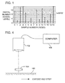
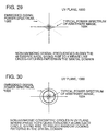
- Fig. 1 shows a classic representation of a one dimensional digital signal.
- the x-axis defines the index numbers of sequence of digital "samples," and the y-axis is the instantaneous value of the signal at that sample. being constrained to exist only at a finite number of levels defined as the "binary depth" of a digital sample.
- the example depicted in Fig. 1 has the value of 2 to the fourth power, or "4 bits,” giving 16 allowed states of the sample value.
- decibel scale is used as a measure of signal and noise in a given recording medium.
- signal-to-noise ratio is generally used, as it will be in this disclosure. As an example, this disclosure refers to signal to noise ratios in terms of signal power and noise power, thus 20 dB represents a 10 times increase in signal amplitude.
- this embodiment embeds an N-bit value onto an entire signal through the addition of a very low amplitude encodation signal which has the look of pure noise.
- N is usually at least 8 and is capped on the higher end by ultimate signal-to-noise considerations and "bit error" in retrieving and decoding the N-bit value.
- the amplitude or power of this added signal is determined by the aesthetic and informational considerations of each and every application using the present methodology. For instance, non-professional video can stand to have a higher embedded signal level without becoming noticeable to the average human eye, while high precision audio may only be able to accept a relatively small signal level lest the human ear perceive an objectionable increase in "hiss.” These statements are generalities and each application has its own set of criteria in choosing the signal level of the embedded identification signal. The higher the level of embedded signal, the more corrupted a copy can be and still be identified. On the other hand, the higher the level of embedded signal, the more objectionable the perceived noise might be, potentially impacting the value of the distributed material.
- the present specification details two different systems.
- the first (termed, for lack of a better name, a "batch encoding” system), applies identification coding to an existing data signal.
- the second (termed, for lack of a better name, a "real time encoding” system), applies identification coding to a signal as it is produced.
- the original signal refers to either the original digital signal or the high quality digitized copy of a non-digital original.
- the N-bit identification word refers to a unique identification binary value, typically having N range anywhere from 8 to 128, which is the identification code ultimately placed onto the original signal via the disclosed transformation process.
- each N-bit identification word begins with the sequence of values '0101,' which is used to determine an optimization of the signal-to-noise ratio in the identification procedure of a suspect signal (see definition below).
- the m'th bit value of the N-bit identification word is either a zero or one corresponding to the value of the m'th place, reading left to right, of the N-bit word.
- the m'th individual embedded code signal refers to a signal which has dimensions and extent precisely equal to the original signal (e.g. both are a 512 by 512 digital image), and which is (in the illustrated embodiment) an independent pseudo-random sequence of digital values. "Pseudo" pays homage to the difficulty in philosophically defining pure randomness, and also indicates that there are various acceptable ways of generating the "random" signal. There will be exactly N individual embedded code signals associated with any given original signal.
- the acceptable perceived noise level refers to an application-specific determination of how much "extra noise,” i.e. amplitude of the composite embedded code signal described next, can be added to the original signal and still have an acceptable signal to sell or otherwise distribute.
- This disclosure uses a I dB increase in noise as a typical value which might be acceptable, but this is quite arbitrary.
- the composite embedded code signal refers to the signal which has dimensions and extent precisely equal to the original signal, (e.g. both are a 512 by 512 digital image), and which contains the addition and appropriate attenuation of the N individual embedded code signals.
- the individual embedded signals are generated on an arbitrary scale, whereas the amplitude of the composite signal must not exceed the pre-set acceptable perceived noise level, hence the need for "attenuation" of the N added individual code signals.
- the distributable signal refers to the nearly similar copy of the original signal, consisting of the original signal plus the composite embedded code signal. This is the signal which is distributed to the outside community, having only slightly higher but acceptable "noise properties" than the original.
- a suspect signal refers to a signal which has the general appearance of the original and distributed signal and whose potential identification match to the original is being questioned. The suspect signal is then analyzed to see if it matches the N-bit identification word.
- the detailed methodology of this first embodiment begins by stating that the N-bit identification word is encoded onto the original signal by having each of the m bit values multiply their corresponding individual embedded code signals, the resultant being accumulated in the composite signal, the fully summed composite signal then being attenuated down to the acceptable perceived noise amplitude, and the resultant composite signal added to the original to become the distributable signal.
- the original signal, the N-bit identification word, and all N individual embedded code signals are then stored away in a secured place.
- a suspect signal is then found.
- This signal may have undergone multiple copies, compressions and decompressions, resamplings onto different spaced digital signals, transfers from digital to analog back to digital media, or any combination of these items.
- the identification process should function to some objective degree of statistical confidence.
- the extent of corruption of the suspect signal and the original acceptable perceived noise level are two key parameters in determining an expected confidence level of identification.
- the identification process on the suspected signal begins by resampling and aligning the suspected signal onto the digital format and extent of the original signal.
- an image has been reduced by a factor of two, it needs to be digitally enlarged by that same factor.
- a piece of music has been "cut out,” but may still have the same sampling rate as the original, it is necessary to register this cut-out piece to the original, typically done by performing a local digital cross-correlation of the two signals (a common digital operation), finding at what delay value the correlation peaks, then using this found delay value to register the cut piece to a segment of the original.
- the signal levels of the suspect signal should be matched in an rms sense to the signal level of the original. This can be done via a search on the parameters of offset, amplification, and gamma being optimized by using the minimum of the mean squared error between the two signals as a function of the three parameters. We can call the suspect signal normalized and registered at this point, or just normalized for convenience.
- the newly matched pair then has the original signal subtracted from the normalized suspect signal to produce a difference signal.
- the difference signal is then cross-correlated with each of the N individual embedded code signals and the peak cross-correlation value recorded.
- the first four bit code ('0101') is used as a calibrator both on the mean values of the zero value and the one value, and on further registration of the two signals if a finer signal to noise ratio is desired (i.e., the optimal separation of the 0101 signal will indicate an optimal registration of the two signals and will also indicate the probable existence of the N-bit identification signal being present.)
- the resulting peak cross-correlation values will form a noisy series of floating point numbers which can be transformed into 0's and 1's by their proximity to the mean values of 0 and 1 found by the 0101 calibration sequence. If the suspect signal has indeed been derived from the original, the identification number resulting from the above process will match the N-bit identification word of the original, bearing in mind either predicted or unknown "bit error” statistics. Signal-to-noise considerations will determine if there will be some kind of "bit error” in the identification process, leading to a form of X% probability of identification where X might be desired to be 99.9% or whatever.
- the next step in our process is to choose N of our N-bit identification word.
- N the number of bits required now are at 4 bits for the 0101 calibration sequence, 16 for the main identification, 8 for the version, and we now throw in another 4 as a further error checking value on the first 28 bits, giving 32 bits as N.
- the final 4 bits can use one of many industry standard error checking methods to choose its four values.
- V dist;n,m V orig;n,m + V comp;n,m *X*sqrt(4+V orig;n,m ⁇ Y)
- dist refers to the candidate distributable image, i.e. we are visually iterating to find what X and Y will give us an acceptable image
- orig refers to the pixel value of the original image
- comp refers to the pixel value of the composite image.
- the n's and m's still index rows and columns of the image and indicate that this operation is done on all 4000 by 4000 pixels.
- the symbol V is the DN of a given pixel and a given image.
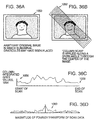
- the first step is to take an issue of the magazine, cut out the page with the image on it, then carefully but not too carefully cut out the two figures from the background image using ordinary scissors. If possible, we will cut out only one connected piece rather than the two figures separately.
- the next step is to subtract the original digital image from the newly normalized suspect image only within the standard mask region. This new image is called the difference image.
- the ultimate benefits of the foregoing process are that obtaining an identification number is fully independent of the manners and methods of preparing the difference image. That is to say, the manners of preparing the difference image, such as cutting, registering, scaling, etcetera, cannot increase the odds of finding an identification number when none exists; it only helps the signal-to-noise ratio of the identification process when a true identification number is present. Methods of preparing images for identification can be different from each other even, providing the possibility for multiple independent methodologies for making a match.
- the manner with which an expert makes an identification determination becomes an integral part of that determination.
- the existence of a multitude of mathematical and statistical approaches to making this determination leave open the possibility that some tests might make positive identifications while others might make negative determinations, inviting further arcane debate about the relative merits of the various identification approaches.
- the N > 1 embodiment avoids this further gray area by presenting a method where no amount of pre-processing of a signal - other than pre-processing which surreptitiously uses knowledge of the private code signals - can increase the likelihood of "calling the coin flip N times in a row,"
- step 8 of Fig. 2 rather than only 'adding' the individual embedded code signals which correspond to a '1' in the N-bit identification word, we will also 'subtract' the individual embedded code signals which correspond to a '0' in the N-bit identification word.
- the first area to be discussed involves the pre-application or pre-exposing of a serial number onto traditional photographic products, such as negative film, print paper, transparencies, etc.
- a serial number itself would be a permanent pan of the normally exposed picture, as opposed to being relegated to the margins or stamped on the back of a printed photograph, which all require separate locations and separate methods of copying.
- the 'serial number' as it is called here is generally synonymous with the N-bit identification word, only now we are using a more common industrial terminology.
- step 11 the disclosure calls for the storage of the "original (image]" along with code images. Then in Fig. 3, step 9, it directs that the original be subtracted from the suspect image, thereby leaving the possible identification codes plus whatever noise and corruption has accumulated. Therefore, the previous disclosure made the tacit assumption that there exists an original without the composite embedded signals.
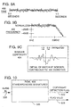
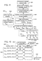
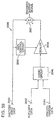
- Fig. 4 has a schematic outlining one potential post-hoc mechanism for pre-exposing film.
- 'Post-hoc' refers to applying a process after the full common manufacturing process of film has already taken place. Eventually, economies of scale may dictate placing this pre-exposing process directly into the chain of manufacturing film.
- Depicted in Fig. 4 is what is commonly known as a film writing system.
- the computer, 106 displays the composite signal produced in step 8, Fig. 2, on its phosphor screen. A given frame of film is then exposed by imaging this phosphor screen, where the exposure level is generally very faint, i.e. generally imperceptible.
- the marketplace will set its own demands on how faint this should be, that is, the level of added 'graininess' as practitioners would put it.
- Each frame of film is sequentially exposed, where in general the composite image displayed on the CRT 102 is changed for each and every frame, thereby giving each frame of film a different serial number.
- the transfer lens 104 highlights the focal conjugate planes of a film frame and the CRT face.
- a succinct definition of the problem is in order at this point. Given a suspect picture (signal), find the embedded identification code IF a code exists at all. The problem reduces to one of finding the amplitude of each and every individual embedded code signal within the suspect picture, not only within the context of noise and corruption as was previously explained, but now also within the context of the coupling between a captured image and the codes. 'Coupling' here refers to the idea that the captured image "randomly biases" the cross-correlation.
- the identification process now estimates the signal amplitude of each and every individual embedded code signal (as opposed to taking the cross-correlation result of step 12, Fig. 3). If our identification signal exists in the suspect picture, the amplitudes thus found will split into a polarity with positive amplitudes being assigned a '1' and negative amplitudes being assigned a '0'. Our unique identification code manifests iiself. If, on the other hand, no such identification code exists or it is someone else's code, then a random gaussian-like distribution of amplitudes is found with a random hash of values.
- the new image is applied to the fast fourier transform routine and a scale factor is eventually found which minimizes the integrated high frequency content of the new image.
- This general type of search operation with its minimization of a particular quantity is exceedingly common.
- the scale factor thus found is the sought-for "amplitude.”
- refinements which are contemplated but not yet implemented are where the coupling of the higher derivatives of the acquired image and the embedded codes are estimated and removed from the calculated scale factor. In other words, certain bias effects from the coupling mentioned earlier are present and should be eventually accounted for and removed both through theoretical and empirical experimentation.
- One such approach to economizing is to have a given set of individual embedded code signals be common to a batch of source materials. For example, one thousand images can all utilize the same basic set of individual embedded code signals. The storage requirements of these codes then become a small fraction of the overall storage requirements of the source material.
- some applications can utilize a universal set of individual embedded code signals, i.e., codes which remain the same for all instances of distributed material. This type of requirement would be seen by systems which wish to hide the N-bit identification word itself, yet have standardized equipment be able to read that word. This can be used in systems which make go/no go decisions at point-of-read locations.
- the potential drawback to this set-up is that the universal codes arc more prone to be sleuthed or stolen; therefore they will not be as secure as the apparatus and methodology of the previously disclosed arrangement. Perhaps this is just the difference between 'high security' and 'air-tight security,' a distinction carrying little weight with the bulk of potential applications.
- 'signal' is often used narrowly to refer to digital data information, audio signals, images, etc.
- a broader interpretation of 'signal,' and the one more generally intended, includes any form of modulation of any material whatsoever.
- the micro-topology of a piece of common paper becomes a 'signal' (e.g. it height as a function of x-y coordinates).
- the reflective properties of a flat piece of plastic (as a function of space also) becomes a signal.
- photographic emulsions, audio signals, and digitized information are not the only types of signals capable of utilizing the principles described herein.
- a machine very much resembling a braille printing machine can be designed so as to imprint unique 'noise-like' indentations as outlined above. These indentations can be applied with a pressure which is much smaller than is typically applied in creating braille, to the point where the patterns are not noticed by a normal user of the paper. But by following the steps of the present disclosure and applying them via the mechanism of micro-indentations, a unique identification code can be placed onto any given sheet of paper, be it intended for everyday stationary purposes, or be it for important documents, legal tender, or other secured material.
- the reading of the identification material in such an embodiment generally proceeds by merely reading the document optically at a variety of angles. This would become an inexpensive method for deducing the micro-topology of the paper surface. Certainly other forms of reading the topology of the paper are possible as well.
- While the first class of embodiments most commonly employs a standard microprocessor or computer to perform the encodation of an image or signal, it is possible to utilize a custom encodation device which may be faster than a typical Von Neuman-type processor. Such a system can be utilized with all manner of serial data streams.
- Piracy is but one concern driving the need for applicant's technology. Another is authentication. Often it is important to confirm that a given set of data is really what it is purported to be (often several years after its generation).
- System 200 can be thought of as an identification coding black box 202.
- the system 200 receives an input signal (sometimes termed the "master” or “unencoded” signal) and a code word, and produces (generally in real time) an identification-coded output signal. (Usually, the system provides key data for use in later decoding.)
- the contents of the "black box” 202 can take various forms.
- An exemplary black box system is shown in Fig. 6 and includes a look-up table 204, a digital noise source 206, first and second scalers 208, 210, an adder/subtracter 212, a memory 214, and a register 216.
- the input signal (which in the illustrated embodiment is an 8 - 20 bit data signal provided at a rate of one million samples per second, but which in other embodiments could be an analog signal if appropriate AID and D/A conversion is provided) is applied from an input 218 to the address input 220 of the look-up table 204. For each input sample (i.e. look-up table address), the table provides a corresponding 8-bit digital output word. This output word is used as a scaling factor that is applied to one input of the first scaler 208.
- the first scaler 208 has a second input, to which is applied an 8-bit digital noise signal from source 206.
- the noise source 206 comprises an analog noise source 222 and an analog-to-digital converter 224 although, again, other implementations can be used.
- the noise source in the illustrated embodiment has a zero mean output value, with a full width half maximum (FWHM) of 50 - 100 digital numbers (e.g. from -75 to +75).
- FWHM full width half maximum
- the first scaler 208 multiplies the two 8-bit words at its inputs (scale factor and noise) to produce -- for each sample of the system input signal -- a 16-bit output word. Since the noise signal has a zero mean value, the output of the first scaler likewise has a zero mean value.
- the output of the first scaler 208 is applied to the input of the second scaler 210.
- the second scaler serves a global scaling function, establishing the absolute magnitude of the identification signal that will ultimately be embedded into the input data signal.
- the scaling factor is set through a scale control device 226 (which may take a number of forms, from a simple rheostat to a graphically implemented control in a graphical user interface), permitting this factor to be changed in accordance with the requirements of different applications.
- the second scaler 210 provides on its output line 228 a scaled noise signal. Each sample of this scaled noise signal is successively stored in the memory 214.
- the output from the first scaler 208 may range between -1500 and +1500 (decimal), while the output from the second scaler 210 is in the low single digits, (such as between -2 and +2).)
- Register 216 stores a multi-bit identification code word.
- this code word consists of 8 bits, although larger code words (up to hundreds of bits) are commonly used. These bits are referenced, one at a time, to control how the input signal is modulated with the scaled noise signal.
- a pointer 230 is cycled sequentially through the bit positions of the code word in register 216 to provide a control bit of "0" or "1" to a control input 232 of the adder/subtracter 212. If, for a particular input signal sample, the control bit is a "1”, the scaled noise signal sample on line 232 is added to the input signal sample. If the control bit is a "0”, the scaled noise signal sample is subtracted from the input signal sample.
- the output 234 from the adder/subtracter 212 provides the black box's output signal.
- the encoded signal can be distributed in well known ways, including convened to printed image form, stored on magnetic media (floppy diskette, analog or DAT tape, etc.), CD-ROM, etc. etc.
- the first decoding method is a difference method, relying on subtraction of corresponding samples of the original signal from the suspect signal to obtain difference samples, which are then examined (typically individually) for deterministic coding indicia (i.e. the stored noise data).
- This approach may thus be termed a "sample-based, deterministic" decoding technique.
- the second decoding method does not make use of the original signal. Nor does it examine particular samples looking for predetermined noise characteristics. Rather, the statistics of the suspect signal (or a portion thereof) are considered in the aggregate and analyzed to discern the presence of identification coding that permeates the entire signal.
- the reference to permeation means the entire identification code can be discerned from a small fragment of the suspect signal. This latter approach may thus be termed a "holographic, statistical" decoding technique.
- Both of these methods begin by registering the suspect signal to match the original. This entails scaling (e.g. in amplitude, duration, color balance, etc.), and sampling (or resampling) to restore the original sample rate. As in the earlier described embodiment, there are a variety of well understood techniques by which the operations associated with this registration function can be performed.
- the first decoding approach proceeds by subtracting the original signal from the registered, suspect signal, leaving a difference signal.
- the polarity of successive difference signal samples can then be compared with the polarities of the corresponding stored noise signal samples to determine the identification code. That is, if the polarity of the first difference signal sample matches that of the first noise signal sample, then the first bit of the identification code is a "1.” (In such case, the polarity of the 9th, 17th, 25th, etc. samples should also all be positive.) If the polarity of the first difference signal sample is opposite that of the corresponding noise signal sample, then the first bit of the identification code is a "0.”
- the sequence of bits that comprise the original code word can be determined. If, as in the illustrated embodiment, pointer 230 stepped through the code word one bit at a time, beginning with the first bit, during encoding, then the first 8 samples of the difference signal can be analyzed to uniquely determine the value of the 8-bit code word.
- the illustrated embodiment relies on recombining the suspect signal with certain noise data (typically the data stored in memory 214), and analyzing the entropy of the resulting signal. "Entropy” need not be understood in its most strict mathematical definition, it being merely the most concise word to describe randomness (noise, smoothness, snowiness, etc.).
- the pointer 230 increments through the code word, one bit for each successive sample of the input signal. If the code word is eight bits in length, then the pointer returns to the same bit position in the code word every eighth signal sample. If this bit is a "1”, noise is added to the input signal; if this bit is a "0”, noise is subtracted from the input signal. Due to the cyclic progression of the pointer 230, every eighth sample of an encoded signal thus shares a characteristic: they are all either augmented by the corresponding noise data (which may be negative), or they are all diminished, depending on whether the bit of the code word then being addressed by pointer 230 is a "1" or a "0".
- the entropy-based decoding process treats every eighth sample of the suspect signal in like fashion.
- the process begins by adding to the 1st, 9th, 17th, 25th, etc. samples of the suspect signal the corresponding scaled noise signal values stored in the memory 214 (i.e. those stored in the 1st, 9th, 17th, 25th, etc., memory locations, respectively).
- the entropy of the resulting signal i.e. the suspect signal with every 8th sample modified is then computed.
- the foregoing step is then repeated, this time subtracting the stored noise values from the 1st, 9th, 17th, 25 etc. suspect signal samples.
- an N-bit code word in this real time embodiment provides benefits analogous to those discussed above in connection with the batch encoding system.
- the present embodiment may be conceptualized as making use of N different noise signals, just as in the batch encoding system.
- the second noise signal is a similar one comprising the scaled noise signal at the 2d, 10th, 18th, 26th, etc., samples, with zeroes at the intervening samples.
- the above-described decoding process tries both adding and subtracting stored noise data to/from the suspect signal in order to find which operation reduces entropy. In other embodiments, only one of these operations needs to be conducted.
- the stored noise data corresponding to every eighth sample of the suspect signal is only added to said samples. If the entropy of the resulting signal is thereby increased, then the corresponding bit of the code word is a "1" (i.e. this noise was added earlier, during the encoding process, so adding it again only compounds the signal's randomness). If the entropy of the resulting signal is thereby decreased, then the corresponding bit of the code word is a "0". A further test of entropy if the stored noise samples are subtracted is not required.
- the statistical reliability of the identification process can be designed to exceed virtually any confidence threshold (e.g. 99.9%, 99.99%, 99.999%, etc. confidence) by appropriate selection of the global scaling factors, etc. Additional confidence in any given application (unnecessary in most applications) can be achieved by rechecking the decoding process.
- confidence threshold e.g. 99.9%, 99.99%, 99.999%, etc. confidence
- One way to recheck the decoding process is to remove the stored noise data from the suspect signal in accordance with the bits of the discerned code word, yielding a "restored" signal (e.g. if the first bit of the code word is found to be "1,” then the noise samples stored in the 1st, 9th, 17th, etc. locations of the memory 214 are subtracted from the corresponding samples of the suspect signal). The entropy of the restored signal is measured and used as a baseline in further measurements. Next, the process is repeated, this lime removing the stored noise data from the suspect signal in accordance with a modified code word.
- the modified code word is the same as the discerned code word, except 1 bit is toggled (e.g. the first).
- the entropy of the resulting signal is determined, and compared with the baseline. If the toggling of the bit in the discerned code word resulted in increased entropy, then the accuracy of that bit of the discerned code word is confirmed. The process repeats, each time with a different bit of the discerned code word toggled, until all bits of the code word have been so checked. Each change should result in an-increase in entropy compared to the baseline value.
- memory 214 contains the scaled noise data. In other embodiments, the unsealed noise data can be stored instead.
- the memory can allocate 8 signed bits to the noise sample, and 16 bits to store the most significant bits of an 18- or 20-bit audio signal sample. This has several benefits. One is that it simplifies registration of a "suspect" signal. Another is that, in the case of encoding an input signal which was already encoded, the data in memory 214 can be used to discern which of the encoding processes was performed first. That is, from the input signal data in memory 214 (albeit incomplete), it is generally possible to determine with which of two code words it has been encoded.
- memory 214 Yet another alternative for memory 214 is that it can be omitted altogether.
- a deterministic noise source in the encoding process, such as an algorithmic noise generator seeded with a known key number.
- the same deterministic noise source, seeded with the same key number can be used in the decoding process. In such an arrangement, only the key number needs be stored for later use in decoding, instead of the large data set usually stored in memory 214.
- a universal decoding process can be implemented. This process uses the same entropy test as the foregoing procedures, but cycles through possible code words, adding/subtracting a small dummy noise value (e.g. less than the expected mean noise value) to every Nth sample of the suspect signal, in accordance with the bits of the code word being tested. until a reduction in entropy is noted.
- a small dummy noise value e.g. less than the expected mean noise value
- the embodiment 240 of Fig. 7 includes a noise store 242 into which noise from source 206 is written during the identification-coding of the input signal with a first code word.
- the noise source of Fig. 7 is shown outside of the real time encoder 202 for convenience of illustration.
- additional identification-coded versions of the input signal can be produced by reading the stored noise data from the store and using it in conjunction with second through Nth code words to encode the signal.
- One such implementation includes a plurality of adder/subtracter circuits 212, each driven with the same input signal and with the same scaled noise signal, but with different code words. Each, then, produces a differently encoded output signal.
- the decoding process need not always discern every bit of the code word.
- the application may require identifying only a group of codes to which the suspect signal belongs.
- high order bits of the code word might indicate an organization to which several differently coded versions of the same source material were provided, with low-order bits identifying specific copies.
- To identify the organization with which a suspect signal is associated it may not be necessary to examine the low order bits, since the organization can be identified by the high order bits alone.) If the identification requirements can be met by discerning a subset of the code word bits in the suspect signal, the decoding process can be shortened.
- Videotaped productions e.g. television programming
- Each frame of a videotaped production can be identification-coded with a unique code number, processed in real-time with an arrangement 248 like that shown in Fig. 8.
- the noise source 206 resets (e.g. to repeat the sequence just produced) and an identification code increments to the next value.
- Each frame of the videotape is thereby uniquely identification-coded.
- the encoded signal is stored on a videotape for long term storage (although other storage media, including laser disks, can be used).
- the look-up table 204 in the illustrated embodiment exploits the fact that high amplitude samples of the input data signal can tolerate (without objectionable degradation of the output signal) a higher level of encoded identification coding than can low amplitude input samples.
- input data samples having decimal values of 0, 1 or 2 may correspond (in the look-up table 204) to scale factors of unity (or even zero), whereas input data samples having values in excess of 200 may correspond to scale factors of 15.
- the scale factors and the input sample values correspond by a square root relation. That is, a four-fold increase in a value of the sampled input signal corresponds to approximately a two-fold increase in a value of the scaling factor associated therewith.
- the parenthetical reference to zero as a scaling factor alludes to cases, e.g., in which the source signal is temporally or spatially devoid of information content.
- a region characterized by several contiguous sample values of zero may correspond to a jet black region of the frame.
- a scaling value of zero may be appropriate here since there is essentially no image data to be pirated.
- bits of the code word can be used other than sequentially for this purpose. Indeed, bits of the code word can be selected in accordance with any predetermined algorithm.
- the dynamic scaling of the noise signal based on the instantaneous value of the input signal is an optimization that can be omitted in many embodiments. That is, the look-up table 204 and the first scaler 208 can be omitted entirely, and the signal from the digital noise source 206 applied directly (or through the second, global scaler 210) to the adder/subtracter 212.
- noise signal with another mean value can readily be used, and D.C. compensation (if needed) can be effected elsewhere in the system.
- noise source 206 is also optional.
- a variety of other signal sources can be used, depending on application-dependent constraints (e.g. the threshold at which the encoded identification signal becomes perceptible).
- the level of the embedded identification signal is low enough that the identification signal needn't have a random aspect: it is imperceptible regardless of its nature.
- a pseudo random source 206 is usually desired because it provides the greatest identification code signal S/N ratio (a somewhat awkward term in this instance) for a level of imperceptibility of the embedded identification signal.
- identification coding need not occur after a signal has been reduced to stored form as data (i.e. "fixed in tangible form," in the words of the U.S. Copyright Act).
- data i.e. "fixed in tangible form," in the words of the U.S. Copyright Act.
- identification coding the audio before it drives concert hall speakers, unauthorized recordings of the concert can be traced to a particular place and time.
- live audio sources such as 911 emergency calls can be encoded prior to recording so as to facilitate their later authentication.
- black box embodiment has been described as a stand alone unit, it will be recognized that it can be integrated into a number of different tools/instruments as a component.
- a scanner which can embed identification codes in the scanned output data. (The codes can simply serve to memorialize that the data was generated by a particular scanner).
- real-time encoder 202 has been illustrated with reference to a particular hardware implementation, it will be recognized that a variety of other implementations can alternatively be employed. Some utilize other hardware configurations. Others make use of software routines for some or all of the illustrated functional blocks. (The software routines can be executed on any number of different general purpose programmable computers, such as 80x86 PC-compatible computers, RISC-based workstations, etc.)
- Gaussian noise "white noise”
- noise generated directly from application instrumentation as a few of the many examples of the kind of carrier signal appropriate to carry a single bit of information throughout an image or signal. It is possible to be even more proactive in “designing” characteristics of noise in order to achieve certain goals.
- the "design” of using Gaussian or instrumental noise was aimed somewhat toward “absolute” security. This section of the disclosure takes a look at other considerations for the design of the noise signals which may be considered the ultimate carriers of the identification information.
- the noise carrier signal e.g. the Nth embedded code signal in the first embodiment; the scaled noise data in the second embodiment
- the noise carrier signal e.g. the Nth embedded code signal in the first embodiment; the scaled noise data in the second embodiment
- the noise carrier signal e.g. the Nth embedded code signal in the first embodiment; the scaled noise data in the second embodiment
- One example is the following. It is recognized that a true Gaussian noise signal has the value '0' occur most frequently, followed by 1 and -1 at equal probabilities to each other but lower than '0'. 2 and -2 next, and so on. Clearly, the value zero carries no information as it is used in such an embodiment.
- identification signal energy would always be applied at all parts of the signal.
- trade-offs include: there is a (probably negligible) lowering of security of the codes in that a "deterministic component" is a part of generating the noise signal. The reason this might be completely negligible is that we still wind up with a coin flip type situation on randomly choosing the 1 or the -1.
- Another trade-off is that this type of designed noise will have a higher threshold of perceptibility, and will only be applicable to applications where the least significant bit of a data stream or image is already negligible relative to the commercial value of the material, i.e. if the least significant bit were stripped from the signal (for all signal samples), no one would know the difference and the value of the material would not suffer.
- the noise-like embedded code signals which carry the bits of information of the identification signal should be unique to each and every encoded signal, or, slightly less restrictive, that embedded code signals should be generated sparingly, such as using the same embedded codes for a batch of 1000 pieces of film, for example. Be this as it may, there is a whole other approach to this issue wherein the use of what we will call "universal" embedded code signals can open up large new applications for this technology.
- the economics of these uses would be such that the de facto lowered security of these universal codes (e.g. they would be analyzable by time honored cryptographic decoding methods, and thus potentially thwarted or reversed) would be economically negligible relative to the economic gains that the intended uses would provide.
- Piracy and illegitimate uses would become merely a predictable "cost" and a source of uncollected revenue only; a simple line item in an economic analysis of the whole.
- a good analogy of this is in the cable industry and the scrambling of video signals. Everybody seems to know that crafty, skilled technical individuals, who may be generally law abiding citizens, can climb a ladder and flip a few wires in their cable junction box in order to get all the pay channels for free.
- the cable industry knows this and takes active measures to stop it and prosecute those caught, but the "lost revenue" derived from this practice remains prevalent but almost negligible as a percentage of profits gained from the scrambling system as a whole.
- the scrambling system as a whole is an economic success despite its lack of "absolute security.”
- Universal embedded codes generally refer to the idea that knowledge of the exact codes can be distributed.
- the embedded codes won't be put into a dark safe never to be touched until litigation arises (as alluded to in other pans of this disclosure), but instead will be distributed to various locations where on-the-spot analysis can take place. Generally this distribution will still take place within a security controlled environment, meaning that steps will be taken to limit the knowledge of the codes to those with a need to know. Instrumentation which attempts to automatically detect copyrighted material is a non-human example of "something" with a need to know the codes.
- libraries of universal codes simply means that applicant's techniques are employed as described, except for the fact that only a limited set of the individual embedded code signals are generated and that any given encoded material will make use of some sub-set of this limited “universal set.”
- An example is in order here.
- a photographic print paper manufacturer may wish to pre-expose every piece of 8 by 10 inch print paper which they sell with a unique identification code. They also wish to sell identification code recognition software to their large customers, service bureaus, stock agencies, and individual photographers, so that all these people can not only verify that their own material is correctly marked, but so that they can also determine if third party material which they are about to acquire has been identified by this technology as being copyrighted. This latter information will help them verify copyright holders and avoid litigation, among many other benefits.
- the reason for picking 50 instead of just 16 is one of a little more added security, where if it were the same 16 embedded codes for all photographic sheets, not only would the serial number capability be limited to 2 to the 16th power, but lesser and lesser sophisticated pirates could crack the codes and remove them using software tools.
- the raw information content of an embedded code is then approximately 3/8th's bytes times 450K or about 170 Kilobytes. Digital compression can reduce this further. All of these decisions are subject to standard engineering optimization principles as defined by any given application at hand, as is well known in the art. Thus we find that 50 of these independent embedded codes will amount to a few Megabytes. This is quite a reasonable level to distribute as a "library" of universal codes within the recognition software. Advanced standard encryption devices could be employed to mask the exact nature of these codes if one were concerned that would-be pirates would buy the recognition software merely to reverse engineer the universal embedded codes. The recognition software could simply unencrypt the codes prior to applying the recognition techniques taught in this disclosure.
- the recognition software itself would certainly have a variety of features, but the core task it would perform is determining if there is some universal copyright code within a given image.
- the key questions become WHICH 16 of the total 50 universal codes it might contain, if any, and if there are 16 found, what are their bit values.
- the key variables in determining the answers to these questions are: registration, rotation, magnification (scale), and extent. In the most general case with no helpful hints whatsoever, all variables must be independently varied across all mutual combinations, and each of the 50 universal codes must then be checked by adding and subtracting to see if an entropy decrease occurs.
- the libraries of universal codes require the storage and transmittal of Megabytes of independent, generally random data as the keys with which to unlock the existence and identity of signals and imagery that have been marked with universal codes.
- various deterministic formulas can be used which "generate” what appear to be random data/image frames, thereby obviating the need to store all of these codes in memory and interrogate each of the "50" universal codes.
- Deterministic formulas can also assist in speeding up the process of determining the ID code once one is known to exist in a given signal or image.
- deterministic formulas lend themselves to sleuthing by less sophisticated pirates. And once sleuthed, they lend themselves to easier communication, such as posting on the Internet to a hundred newsgroups. There may well be many applications which do not care about sleuthing and publishing, and deterministic formulas for generating the individual universal embedded codes might be just the ticket.
- This category is a bit of a hybrid of the first two, and is most directed at truly large scale implementations of the principles of this technology.
- the applications employing this class arc of the type where staunch security is much less important than low cost, large scale implementation and the vastly larger economic benefits that this enables.
- One exemplary application is placement of identification recognition units directly within modestly priced home audio and video instrumentation (such as a TV). Such recognition units would typically monitor audio and/or video looking for these copyright identification codes, and thence triggering simple decisions based on the findings, such as disabling or enabling recording capabilities, or incrementing program specific billing meters which are transmitted back to a central audio/video service provider and placed onto monthly invoices. Likewise, it can be foreseen that "black boxes" in bars and other public places can monitor (listen with a microphone) for copyrighted materials and generate detailed reports, for use by ASCAP, BMI, and the like.
- a core principle of simple universal codes is that some basic industry standard "noiselike" and seamlessly repetitive patterns are injected into signals, images, and image sequences so that inexpensive recognition units can either A) determine the mere existence of a copyright "flag", and B) additionally to A, determine precise identification information which can facilitate more complex decision making and actions.
- the basic principles of generating the individual embedded noise signals need to be simplified in order to accommodate inexpensive recognition signal processing circuitry, while maintaining the properties of effective randomness and holographic permeation.
- the codes themselves would border on public domain information (much as cable scrambling boxes are almost de facto public domain), leaving the door open for determined pirates to develop black market countermeasures, but this situation would be quite analogous to the scrambling of cable video and the objective economic analysis of such illegal activity.
- FIG. 9 has an example of what the waveform of an industry standard noise second might look like, both in the time domain 400 and the frequency domain 402. It is by definition a continuous function and would adapt to any combination of sampling rates and bit quantizations. It has a normalized amplitude and can be scaled arbitrarily to any digital signal amplitude.
- the signal level and the first M'th derivatives of the signal are continuous at the two boundaries 404 (Fig.
- this identification technique can extend far beyond the low cost home implementations discussed here, where studios could use the technique, and monitoring stations could be set up which literally monitor hundreds of channels of information simultaneously, searching for marked data streams, and furthermore searching for the associated identity codes which could be tied in with billing networks and royalty tracking systems.
- This basic, standardized noise signature is seamlessly repeated over and over again and added to audio signals which are to be marked with the base copyright identification.
- This basic, standardized noise signature is seamlessly repeated over and over again and added to audio signals which are to be marked with the base copyright identification.
- Part of the reason for the word "simple" is seen here: clearly pirates will know about this industry standard signal, but their illicit uses derived from this knowledge, such as erasure or corruption, will be economically minuscule relative to the economic value of the overall technique to the mass market. For most high end audio this signal will be some 80 to 100 dB down from full scale, or even much further; each situation can choose its own levels though certainly there will be recommendations.
- the amplitude of the signal can be modulated according to the audio signal levels to which the noise signature is being applied, i.e. the amplitude can increase significantly when a drum beats, but not so dramatically as to become audible or objectionable.
- detection of the copyright noise signature involves comparing the time averaged power level of an audio signal with the time averaged power level of that same audio signal which has had the noise signature subtracted from it. If the audio signal with the noise signature subtracted has a lower power level that the unchanged audio signal, then the copyright signature is present and some status flag to that effect needs to be set.
- the main engineering subtleties involved in making this comparison include: dealing with audio speed playback discrepancies (e.g.
- Fig. 10 shows one such integrated circuit 506.
- the audio signal comes in, 500, either as a digital signal or as an analog signal to be digitized inside the IC 500, and the output is a flag 502 which is set to one level if the copyright noise signature is found, and to another level if it is not found.
- the standardized noise signature waveform is stored in Read Only Memory, 504, inside the IC 506.
- Read Only Memory, 504 There will be a slight time delay between the application of an audio signal to the IC 506 and the output of a valid flag 502, due to the need to monitor some finite portion of the audio before a recognition can place.
- Fig. 11 depicts a flow chart for any of: an analog signal processing network, a digital signal processing network, or programming steps in a software program.
- a beat signal 618 of approximately 4 second period will show up on the output signal 613, and it remains to detect this beat signal with a step such as in Fig. 12, 622.
- Case 1, 614 is a steady noisy signal which exhibits no periodic beating. 125% at step 604 is chosen arbitrarily here, where engineering considerations would determine an optimal value, leading to different beat signal frequencies 618. Whereas waiting 4 seconds in this example would he quite a while, especially if you would want to detect at least two or three beats, Fig. 12 outlines how the basic design of Fig.
- 11 could be repeated and operated upon various delayed versions of the input signal, delayed by something like 1/20th of a second, with 20 parallel circuits working in concert each on a segment of the audio delayed by 0.05 seconds from their neighbors.
- a beat signal will show up approximately every 1/5th of a second and will look like a travelling wave down the columns of beat detection circuits. The existence or absence of this travelling beat wave triggers the detection flag 502.
- an audio signal monitor 624 which would ensure that, for example, at least two seconds of audio has been heard before setting the flag valid signal 508.
- the noise signature signal is either there (1) or it isn't (0).
- serial number information For many applications, it would be nice to detect serial number information as well, which could then be used for more complex decisions, or for logging information on billing statements or whatnot.
- N independent noise signatures as depicted in Fig. 9 instead of one single such signature.
- one such signature would be the master upon which the mere existence of a copyright marking is detected, and this would have generally higher power than the others, and then the other lower power "identification" noise signatures would be embedded into audio.
- Recognition circuits once having found the existence of the primary noise signature, would then step through the other N noise signatures applying the same steps as described above. Where a beat signal is detected, this indicates the bit value of '1', and where no beat signal is detected, this indicates a bit value of '0'. It might be typical that N will equal 32, that way 2 32 number of identification codes are available to any given industry employing this technology.
- holographic has been used in this disclosure to describe how an identification code number is distributed in a largely integral form throughout an encoded signal or image. This also refers to the idea that any given fragment of the signal or image contains the entire unique identification code number. As with physical implementations of holography, there are limitations on how small a fragment can become before one begins to lose this property, where the resolution limits of the holographic media are the main factor in this regard for holography itself. In the case of an uncorrupted distribution signal which has used the encoding device of Fig.
- the applicant also uses the analogy that the unique identification code number is "wallpapered" across an image (or signal). That is, it is repealed over and over again all throughout an image.
- This repetition of the ID code number can be regular, as in the use of the encoder of Fig. 5, or random itself, where the bits in the ID code 216 of Fig. 6 are not stepped through in a normal repetitive fashion but rather are randomly selected on each sample, and the random selection stored along with the value of the output 228 itself.
- the information carrier of the ID code, the individual embedded code signal does change across the image or signal.
- the wallpaper analogy summarizes: the ID code repeats itself over and over, but the patterns that each repetition imprints change randomly accordingly to a generally unsleuthable key.
- identification coding withstand lossy data compression, and subsequent decompression.
- Such compression is finding increasing use, particularly in contexts such as the mass distribution of digitized entertainment programming (movies, etc.).
- the CCITT standards are widely used in black-and-white document compression (e.g. facsimile and document-storage).
- JPEG is most widely used with still images.
- MPEG is most widely used with moving images.
- JBIG is a likely successor to the CCITT standards for use with black-and-white imagery.
- Such techniques are well known to those in the lossy data compression field; a good overview can be found in Pennebaker et al, JPEG, Still Image Data Compression Standard , Van Nostrand Reinhold. N.Y., 1993.
- This disclosure concentrates on what above was called wallpapering a single identification code across an entire signal. This appears to be a desirable feature for many applications. However, there are other applications where it might be desirable to pass messages or to embed very long strings of pertinent identification information in signals and images. One of many such possible applications would be where a given signal or image is meant to be manipulated by several different groups, and that certain regions of an image are reserved for each group's identification and insertion of pertinent manipulation information.
- the code word 216 in Fig. 6 can actually change in some pre-defined manner as a function of signal or image position.
- the code could change for each and every raster line of the digital image. It might be a 16 bit code word, 216, but each scan line would have a new code word, and thus a 480 scan line image could pass a 980 (480 x 2 bytes) byte message.
- a receiver of the message would need to have access to either the noise signal stored in memory 214, or would have to know the universal code structure of the noise codes if that method of coding was being used. To the best of applicant's knowledge, this is a novel approach to the mature field of steganography.
- an economizing step was taken whereby the N independent and source-signal-coextensive embedded code signals were so designed that the non-zero elements of any given embedded code signal were unique to just that embedded code signal and no others. Said more carefully, certain pixels/sample points of a given signal were "assigned" to some pre-determined m'th bit location in our N-bit identification word. Furthermore, and as another basic optimization of implementation, the aggregate of these assigned pixels/samples across all N embedded code signals is precisely the extent of the source signal, meaning each and every pixel/sample location in a source signal is assigned one and only one m'th bit place in our N-bit identification word.
- Fig. 13 pictorially represents the steps involved.
- the user is one "Alien Productions.” They first create an image canvas which is coextensive to the size of the video frames of their movie “Bud's Adventures.” On this canvas they print the name of the movie, they place their logo and company name.
- a standard image 700 which forms the initial basis for the creation of a master Snowy Image (master code signal) which will be added into the original movie frame, creating an output distributable frame.
- This image 700 can be either black & white or color.
- the process of turning this image 700 into a pseudo random master code signal is alluded to by the encryption/scrambling routine 702, wherein the original image 700 is passed through any of dozens of well known scrambling methods.
- This Master Snowy Image 704 is then the signal which is modulated by our N-bit identification word as outlined in other sections of the disclosure, the resulting modulated signal is then scaled down in brightness to the acceptable perceived noise level, and then added to the original frame to produce the distributable frame.
- the encryption/scrambling routine 702 has a straightforward and known decryption/descrambling method which tolerates bit truncation errors, it is generally impossible to fully re-create the image 700 based upon having the distributable frame, the N-bit identification code word, the brightness scaling factor used, and the number of the decryption routine to be used.
- the reason that an exact recreation of the image 700 is impossible is due to the scaling operation itself and the concomitant bit truncation. For the present discussion, this whole issue is somewhat academic, however.
- Fig. 13 A variation on the theme of Fig. 13 is to actually place the N-bit identification code word directly into the logo image 700. In some sense this would be self-referential. Thus when we pull out our stored logo image 700 it already contains visually what our identification word is, then we apply encryption routine #28 to this image, scale it down, then use this version to decode a suspect image using the techniques of this disclosure. The N bit word thus found should match the one contained in our logo image 700.
- One desirable feature of the encryption/scrambling routine 702 might be (but is certainly not required to be) that even given a small change in the input image 700, such as a single digit change of the frame number, there would be a huge visual change in the output scrambled master snowy image 704.
- the actual scrambling routine may change as a function of frame numbers, or certain "seed" numbers typically used within pseudo-randomizing functions could change as a function of frame number. All manner of variations are thus possible, all helping to maintain high levels of security.
- engineering optimization considerations will begin to investigate the relationship between some of these randomizing methods, and how they all relate to maintaining acceptable signal strength levels through the process of transforming an uncompressed video stream into a compressed video stream such as with the MPEG compression methodologies.
- Another desired feature of the encryption process 702 is that it should be informationally efficient, i.e., that given any random input, it should be able to output an essentially spatially uniform noisy image with little to no residual spatial patterns beyond pure randomness. Any residual correlated patterns will contribute to inefficiency of encoding the N-bit identification word, as well as opening up further tools to would-be pirates to break the system.
- FIG. 13 Another feature of the method of Fig. 13 is that there is more intuitional appeal to using recognizable symbols as part of a decoding system, which should then translate favorably in the essentially lay environment of a courtroom. It strengthens the simplicity of the coin flip vernacular mentioned elsewhere. Jury members or judges will better relate to an owner's logo as being a piece of the key of recognizing a suspect copy as being a knock-off.
- the logo image 700 does not need to be randomized. The steps could equally apply straight to the logo image 700 directly. It is not entirely clear to the inventor what practical goal this might have.
- N-bit identification word it is desirable in some applications for the N-bit identification word to actually signify names, companies, strange words, messages, and the like. Most of this disclosure focuses on using the N-bit identification word merely for high statistical security, indexed tracking codes, and other index based message carrying. The information carrying capacity of "invisible signatures" inside imagery and audio is somewhat limited, however, and thus it would be wise to use our N bits efficiently if we actually want to "spell out" alphanumeric items in the N-bit identification word.
- One way to do this is to define, or to use an already existing, reduced bit (e.g. less than 8-bit ASCII) standardized codes for passing alphanumeric messages. This can help to satisfy this need on the part of some applications.
- a simple alphanumeric code could be built on a 5-bit index table, where for example the letters V,X,Q, and Z are not included, but the digits 0 through 9 are included. In this way, a 100 bit identification word could carry with it 20 alphanumeric symbols.
- Another alternative is to use variable bit length codes such as the ones used in text compression routines (e.g. Huffman) whereby more frequently used symbols have shorter bit length codes and less frequently used symbols have longer bit lengths.
- section 1.2 Basic Concepts of Hypothesis Testing of Kassam's book lays out the basic concept of a binary hypothesis, assigning the value "1" to one hypothesis and the value "0" to the other hypothesis.
- the last paragraph of that section is also on point regarding the earlier-described embodiment, i.e., that the "0" hypothesis corresponds to "noise only” case, whereas the "1" corresponds to the presence of a signal in the observations.
- each elemental multiplication operation in an overall dot product can be weighted based upon known a priori statistical information about the difference signal itself. i.e., the signal within which the low level known signals are being sought.
- the interested reader who is not already familiar with these topics is encouraged to read chapter 3 of Kassam to gain a fuller understanding.
- Fig. 14 attempts to set the stage for the reasoning behind this approach.
- the top figure 720 contains a generic look at the differences in the histograms between a typical "problematic" difference signal, i.e., a difference signal which has a much higher overall energy than the embedded signals that may or may not be within it.
- the term "mean-removed" simply means that the means of both the difference signal and the embedded code signal have been removed, a common operation prior to performing a normalized dot product.
- the lower figure 722 then has a generally similar histogram plot of the derivatives of the two signals, or in the case of an image, the scalar gradients. From pure inspection it can be seen that a simple thresholding operation in the derivative transform domain, with a subsequent conversion back into the signal domain, will go a long way toward removing certain innate biases on the dot product "recognition algorithm" of a few paragraphs back. Thresholding here refers to the idea that if the absolute value of a difference signal derivative value exceeds some threshold, then it is replaced simply by that threshold value. The threshold value can be so chosen to contain most of the histogram of the embedded signal.
- Another operation which can be of minor assistance in "alleviating" some of the bias effects in the dot product algorithm is the removal of the low order frequencies in the difference signal, i.e., running the difference signal through a high pass filter, where the cutoff frequency for the high pass filter is relatively near the origin (or DC) frequency.
- Some signal processing operations such as compressing and decompressing an image, as with the JPEG/MPEG formats of image/video compression, create errors in some given transform domain which have cenain correlations and structure.
- JPEG JPEG as an example, if a given image is compressed then decompressed at some high compression ratio, and that resulting image is then fourier transformed and compared to the fourier transform of the original uncompressed image, a definite pattern is clearly visible. This patterning is indicative of correlated error, i.e. error which can be to some extent quantified and predicted.
- the prediction of the grosser properties of this correlated error can then be used to advantage in the heretofore-discussed methods of recognizing the embedded code signals within some suspect image which may have undergone either JPEG compression or any other operation which leaves these telltale correlated error signatures.
- the basic idea is that in areas where there are known higher levels of error, the value of the recognition methods is diminished relative to the areas with known lower levels of correlated errors. It is often possible to quantify the expected levels of error and use this quantification to appropriately weight the retransformed signal values. Using JPEG compression again as an example, a suspect signal can be fourier transformed, and the fourier space representation may clearly show the telltale box grid pattern.
- the fourier space signal can then be "spatially filtered” near the grid points, and this filtered representation can then be transformed back into its regular time or space domain to then be run through the recognition methods presented in this disclosure.
- any signal processing method which creates non-uniform error sources can be transformed into the domain in which these error sources are non-uniform, the values at the high points of the error sources can be attenuated, and the thusly "filtered” signal can be transformed back into the time/space domain for standard recognition.
- this whole process will include the lengthy and arduous step of "characterizing" the typical correlated error behavior in order to "design" the appropriate filtering profiles.
- One embodiment actually uses the MPEG compression standard as a piece of a solution.
- Other motion image compression schemes could equally well be used, be they already invented or yet to be invented.
- This example also utilizes the scrambled logo image approach to generating the master snowy image as depicted in Fig. 13 and discussed in the disclosure.
- a “compressed master snowy image” is independently rendered as depicted in Fig. 15.
- “Rendered” refers to the generally well known technique in video, movie and animation production whereby an image or sequence of images is created by constructive techniques such as computer instructions or the drawing of animation cells by hand.
- "to render" a signature movie in this example is essentially to let either a computer create it as a digital file or to design some custom digital electronic circuitry to create it.
- the overall goal of the procedure outlined in Fig. 15 is to apply the invisible signatures to the original movie 762 in such a way that the signatures do not degrade the commercial value of the movie, memorialized by the side-by-side viewing, 768, AND in such a way that the signature optimally survives through the MPEG compression and decompression process.
- the use of the MPEG process in particular is an example of the generic process of compression.
- the example presented here has definite room for engineering variations.
- Fig. 15 we begin with the simple stepping through of all Z frames of a movie or video. For a two hour movie played at 30 frames per second, Z turns out to be (30*2*60*60) or 216,000.
- the inner loop of 700, 702 and 704 merely mimics Fig. 13's steps.
- the logo frame optionally can change during the stepping through frames.
- the two arrows emanating from the box 704 represent both the continuation of the loop 750 and the depositing of output frames into the rendered master Snowy Image 752.
- a Markov process is one in which a sequence of events takes place and in general there is no memory between one step in the sequence and the next.
- a Markovian sequence of images would be one in which there is no apparent or appreciable correlation between a given frame and the next.
- the resulting "movie" would be a fine example of a Markovian movie.
- One point of this discussion is that depending on how the logo frames are rendered and depending on how the encryption/scrambling step 702 is performed, the Master Snowy Movie 752 will exhibit some generally quantifiable degree of Markovian characteristics. The point of this point is that the compression procedure itself will be affected by this degree of Markovian nature and thus needs to be accounted for in designing the process of Fig. 15.
- step 754 is to crudely segregate the initially rendered Snowy Movie 752 into two components, the component which survives the compression process 754 which is 756, and the component which does not survive, also crudely estimated using the difference operation 758 to produce the "Cheap Master Snowy Movie" 760.
- a data file begins with generally a comprehensive set of information about the file as a whole, often including information about who the author or copyright holder of the data is, if there is a copyright holder at all.
- This header 800 is then typically followed by the data itself 802, such as an audio stream, a digital image, a video stream, or compressed versions of any of these items. This is all exceedingly known and common in the industry.
- the N-bit identification word can be used to essentially "wallpaper" a given simple message throughout an image (as depicted) or audio data stream, thereby reinforcing some message already contained in a traditional header. This is referred to as "header verification" in the title of this section.
- header verification in the title of this section.
- the thinking here is that less sophisticated would-be pirates and abusers can alter the information content of header information, and the more secure techniques of this technology can thus be used as checks on the veracity of header information.
- the code message such as "joe's image” in the header, matches the repeated message throughout an image, then a user obtaining the image can have some higher degree of confidence that no alteration of the header has taken place.
- the header can actually carry the N-bit identification word so that the fact that a given data set has been coded via the methods of this technology can be highlighted and the verification code built right into the header.
- this data file format has not been created yet since the principles of this technology are currently not being employed.
- leader string on an otherwise entirely empirical data stream.
- This leader string would plain and simple contain the numeric length, in elemental data units, of the entire data file not including the leader string, and the number of bits of depth of a single data element (e.g. its number of grey levels or the number of discrete signal levels of an audio signal).
- universal codes as described in this specification would be used to read the N-bit identification word written directly within the empirical data. The length of the empirical data would need to be long enough to contain the full N bits. The N-bit word would effectively transmit what would otherwise be contained in a traditional header.
- Fig. 17 depicts such a data format and calls it the "universal empirical data format.”
- the leader string 820 is comprised of the 64 bit string length 822 and the 32 bit data word size 824.
- the data stream 826 then immediately follows, and the information traditionally contained in the header but now contained directly in the data stream is represented as the attached dotted line 828. Another term used for this attached information is a "shadow channel" as also depicted in Fig. 17.
- leader string Yet another element that may need to be included in the leader string is some sort of complex check sum bits which can verify that the whole of the data file is intact and unaltered. This is not included in Fig. 17.
- a variant on the theme of dynamic codes is the use of universal codes on systems which have a priori assigned knowledge of which codes to use when.
- One way to summarize this possibility is the idea of "the daily password.”
- the password in this example represents knowledge of which set of universal codes is currently operative, and these change depending on some set of application-specific circumstances. Presumably many applications would be continually updating the universal codes to ones which had never before been used, which is often the case with the traditional concept of the daily password. Part of a currently transmitted N-bit identification word could be the passing on of the next day's password, for example. Though time might be the most common trigger events for the changing of passwords, there could be event based triggers as well.
- Digital Video And Internet Company XYZ has developed a delivery system of its product which relies on a non-symmetric universal coding which double checks incoming video to see if the individual frames of video itself, the visual data, contain XYZ's own relatively high security internal signature codes using the methods of this technology. This works well and fine for many delivery situations, including their Internet tollgate which does not pass any material unless both the header information is verified AND the in-frame universal codes are found.
- another piece of their commercial network performs mundane routine monitoring on Internet channels to look for unauthorized transmission of their proprietary creative property. They control the encryption procedures used, thus it is no problem for them to unencrypt creative property, including headers, and perform straightforward checks.
- a pirate group that wants to traffic material on XYZ's network has determined how to modify the security features in XYZ's header information system, and they have furthermore discovered that by simply rotating imagery by 10 or 20 degrees, and transmitting it over XYZ's network, the network doesn't recognize the codes and therefore does not flag illicit uses of their material, and the receiver of the pirate's rotated material simply unrotates it.
- the non-symmetric universal codes are quite acceptable for the "enablement of authorized action based on the finding of the codes," whereas it can be somewhat easily by-passed in the case of "random monitoring (policing) for the presence of codes.”
- the non-symmetric universal codes may very well catch 90% of illicit uses. i.e. 90% of the illicit users wouldn't bother even going to the simple by-pass of rotation.
- the use of quasi-rotationally symmetric universal codes is called for. "Quasi" derives from the age old squaring the circle issue, in this instance translating into not quite being able to represent a full incrementally rotational symmetric 2-D object on a square grid of pixels.
- the “ring” is the only full rotationally symmetric two dimensional object.
- the “disk” can be seen as a simple finite series of concentric and perfectly abutted rings having width along their radial axis.
- the “ring” needs to be the starting point from which a more robust universal code standard for images is found.
- the ring also will fit nicely into the issue of scale/magnification changes, where the radius of a ring is a single parameter to keep track of and account for.
- Another property of the ring is that even the case where differential scale changes are made to different spatial axes in an image, and the ring turns into an oval, many of the smooth and quasi-symmetric properties that any automated monitoring system will be looking for are generally maintained.
- ring-based universal codes is what the inventor refers to as “knot patterns” or simply “knots,” in deference to woven Celtic knot patterns which were later refined and exalted in the works of Leonardo Da Vinci (e.g. Mona Lisa, or his knot engravings). Some rumors have it that these drawings of knots were indeed steganographic in nature, i.e. conveying messages and signatures; all the more appropriate. Figs. 18 and 19 explore some of the fundamental properties of these knots.
- knot patterns Two simple examples of knot patterns are depicted by the supra-radial knots, 850 and the radial knots 852.
- the names of these types are based on the central symmetry point of the splayed rings and whether the constituent rings intersect this point, are fully outside it, or in the case of sub-radial knots the central point would be inside a constituent circle.
- the examples of 850 and 852 clearly show a symmetrical arrangement of 8 rings or circles. "Rings" is the more appropriate term. as discussed above, in that this term explicitly acknowledges the width of the rings along the radial axis of the ring. It is each of the individual rings in the knot patterns 850 and 852 which will be the carrier signal for a single associated bit plane in our N-bit identification word.
- the knot patterns 850 and 852 each are an 8-bit carrier of information. Specifically, assuming now that the knot patterns 850 and 852 are luminous rings on a black background, then the "addition" of a luminous ring to an independent source image could represent a "1" and the "subtraction” of a luminous ring from an independent source image could represent a "0.” The application of this simple encoding scheme could then be replicated over and over as in Fig. 19 and its mosaic of knot patterns, with the ultimate step of adding a scaled down version of this encoded (modulated) knot mosaic directly and coextensively to the original image, with the resultant being the distributable image which has been encoded via this universal symmetric coding method.
- a procedure for, first, checking for the mere existence of these knot patterns and, second, for reading of the N-bit identification word is as follows.
- a suspect image is first fourier transformed via the extremely common 2D FFT computer procedure. Assuming that we don't know the exact scale of the knot patterns, i.e., we don't know the radius of an elemental ring of the knot pattern in the units of pixels, and that we don't know the exact rotational state of a knot pattern, we merely inspect (via basic automated pattern recognition methods) the resulting magnitude of the Fourier transform of the original image for telltale ripple patterns (concentric low amplitude sinusoidal rings on top of the spatial frequency profile of a source image).
- the ring patterns are somewhat inefficient in their "covering" of the full image space and in using all of the information carrying capacity of an image extent.
- the ring patterns themselves will almost need to be more visible to the eye if they are applied, say, in a straightforward additive way to an 8-bit black and white image.
- the "8" rings of Fig. 18, 850 and 852 is a rather low number, and moreover, there is a 22 and one half degree rotation which could be applied to the figures which the recognition methods would need to contend with (360 divided by 8 divided by 2).
- Fig. 18 shows an example of a key feature of a "knot" (as opposed to a pattern of rings) in that where patterns would supposedly intersect, a virtual third dimension is posited whereby one strand of the knot takes precedence over another strand in some predefined way; see item 854.
- the brightness or dimness of a given intersection point in the knot patterns would be "assigned" to one and only one strand, even in areas where more than two strands overlap.
- a major improvement to the nominal knot pattern system previously described directly addresses practical difficulties (1), the inefficient covering, (2) the unwanted visibility of the rings, and (6) the need for higher levels of security.
- This improvement also indirectly address item (4) the overlapping issue, which has been discussed in the last paragraph.
- This major improvement is the following: just prior to the step where the mosaic of the encoded knot patterns is added to an original image to produce a distributable image, the mosaic of encoded knot patterns, 866, is spatially filtered (using common 2D FFT techniques) by a standardized and (generally smoothly) random phase-only spatial filter. It is very important to note that this phase-only filter is itself fully rotationally symmetric within the spatial frequency domain, i.e. its filtering effects are fully rotationally symmetric.
- Fig. 20 attempts to give a rough (i.e. non-greyscale) depiction of these phase-only filtered ring patterns.
- the top figure of Fig. 20 is a cross section of a typical brightness contour/profile 874 of one of these phase-only filtered ring patterns. Referenced in the figure is the nominal location of the pre-filtered outer ring center, 870.
- the center of an individual ring, 872 is referenced as the point around which the brightness profile is rotated in order to fully describe the two dimensional brightness distribution of one of these filtered patterns.
- Yet another rough attempt to communicate the characteristics of the filtered ring is depicted as 876, a crude greyscale image of the filtered ring. This phase-only filtered ring, 876 can be referred to as a random ripple pattern.
- Fig. 20 Not depicted in Fig. 20 is the composite effects of phase-only filtering on the knot patterns of Fig. 18, or on the mosaic of knot patterns 866 in Fig. 19.
- Each of the individual rings in the knot patterns 850 or 852 will give rise to a 2D brightness pattern of the type 876, and together they form a rather complicated brightness pattern.
- the resulting phase-only filtered knot patterns begin to take on subtle characteristics which no longer make direct sense to the human eye, but which are still readily discernable to a computer especially after the phase-only filtering is inverse filtered reproducing the original rings patterns.
- this knot tapestry Some basic properties of this knot tapestry are that it retains the basic rotational symmetry of its generator mosaic, it is generally unintelligible to the eye/brain, thus raising it a notch on the sophistication level of reverse engineering, it is more efficient at using the available information content of a grid of pixels (more on this in the next section), and if the basic knot concepts 854 and 864 are utilized, it will not give rise to local "hot spots" where the signal level becomes unduly condensed and hence objectionably visible to a viewer.
- the basic decoding process previously described would now need the additional step of inverse filtering the phase-only filter used in the encoding process.
- This inverse filtering is quite well known in the image processing industry. Provided that the scale of the knot patterns are known a priori , the inverse filtering is straightforward. If on the other hand the scale of the knot patterns is not known, then an additional step of discovering this scale is in order.
- One such method of discovering the scale of the knot patterns is to iteratively apply the inverse phase-only filter to variously scaled version of an image being decoded, searching for which scale-version begins to exhibit noticeable knot patterning.
- a common search algorithm such as the simplex method could be used in order to accurately discover the scale of the patterns.
- the field of object recognition should also be consulted, under the general topic of unknown-scale object detection.
- knot tapestry nicely utilizing a full 256 grey level image, then scaling this down by a factor of 20 in brightness including the bit truncation step, then rescaling this truncated version back up in brightness by the same factor of 20, then inverse phase-only filtering the resultant.
- the resulting knot pattern mosaic will be a noticeably degraded version of the original knot pattern mosaic.
- the point of bringing all of this up is the following: it will be a simply defined, but indeed challenging, engineering task to select the various free parameters of design in the implementation of the knot tapestry method, the end goal being to pass a maximum amount of information about the N-bit identification word within some pre-defined visibility tolerance of the knot tapestry.
- the free parameters include but would not be fully limited to: the radius of the elemental ring in pixels, N or the number of rings, the distance in pixels from the center of a knot pattern to the center of an elemental ring, the packing criteria and distances of one knot pattern with the others, the rules for strand weaving, and the forms and types of phase-only filters to be used on the knot mosaics. It would be desirable to feed such parameters into a computer optimization routine which could assist in their selection. Even this would begin surely as more of an art than a science due to the many non-linear free parameters involved.
- phase-only filtering can assist in the detection of the ring patterns. It does so in that the inverse filtering of the decoding process tends to "blur" the underlying source image upon which the knot tapestry is added, while at the same time “bringing into focus” the ring patterns. Without the blurring of the source image, the emerging ring patterns would have a harder time “competing” with the sharp features of typical images.
- the decoding procedure should also utilize the gradient thresholding method described in another section. Briefly, this is the method where if it is known that a source signal is much larger in brightness than our signature signals, then an image being decoded can have higher gradient areas thresholded in the service of increasing the signal level of the signature signals relative to the source signal.
- Elements of a universal standard would certainly include the mirroring aspects of the header verification methods, where header information is verified by signature codes directly within data. Also, a universal standard would outline how hybrid uses of fully private codes and public codes would commingle. Thus, if the public codes were "stripped" by sophisticated pirates, the private codes would remain intact. A universal standard would specify how invisible signatures would evolve as digital images and audio evolve. Thus, when a given image is created based on several source images, the standard would specify how and when the old signatures would be removed and replaced by new signatures, and if the header would keep track of these evolutions and if the signatures themselves would keep some kind of record.
- a simple-minded approach would be to assign a 2 by 2 block of pixels all to be modulated with the same ultimate signature grey value, rather than modulating a single assigned pixel.
- a more fancy approach is depicted in Fig. 21, where an array of pixel groups is depicted. This is a specific example of a large class of configurations. The idea is that now a cenain small region of pixels is associated with a given unique bit plane in the N-bit identification word, and that this grouping actually shares pixels between bit planes (though it doesn't necessarily have to share pixels, as in the case of a 2x2 block of pixels above).
- Fig. 21 Depicted in Fig. 21 is a 3x3 array of pixels with an example normalized weighting (normalized --> the weights add up to 1).
- the methods of this technology now operate on this elementary "bump," as a unit, rather than on a single pixel. It can be seen that in this example there is a fourfold decrease in the number of master code values that need to be stored, due to the spreading out of the signature signal.
- Applications of this "bump approach" to placing in invisible signatures include any application which will experience a priori known high amounts of blurring, where proper identification is still desired even after this heavy blurring.
- the improvements disclosed here can be used as a way to "seal in” certain instructions directly into empirical data in such a way that all that is needed by a reading machine to recognize instructions and messages is to perform a standardized "recognition algorithm” on the empirical data (providing of course that the machine can at the very least “read” the empirical data properly). All machines could implement this algorithm any old way they choose, using any compilers or internal data formats that they want.
- the "message" being passed could be simply a registered serial number identifying ownership to users who wish to legitimately use and pay for the empirical information.
- the serial number could index into a vast registry of creative property, containing the name or names of the owners, pricing information, billing information, and the like.
- the "message” could also be the clearance of free and public use for some given material.
- Similar ownership identification and use indexing can be achieved in two class data structure methods such as a header, but the use of the single class system of this technology may offer certain advantages over the two class system in that the single class system does not care about file format conversion, header compatibilities, internal data format issues, header/body archiving issues, and media transformations.
- Statistical steganography posits that a sender and receiver both have access to the same master snowy code signal.
- This signal can be entirely random and securely transmitted to both parties, or generated by a shared and securely transmitted lower order key which generates a larger quasi-random master snowy code signal.
- 16 bit chunks of a message will be passed within contiguous 1024 sample blocks of empirical data, and that the receiver will use dot product decoding methods as outlined in this disclosure.
- the sender of the information pre-checks that the dot product approach indeed produces the accurate 16 bit values (that is, the sender pre-checks that the cross-talk between the carrier image and the message signal is not such that the dot product operation will produce an unwanted inversion of any of the 16 bits).
- DSS techniques can be used to verify the integrity of a message when the transmitted data is known to only exist in digital form, whereas internal checksum and error correcting codes can be transmitted in situations where the data may be subject to change and transformation in its transmission. In this latter case, it is best to have longer blocks of samples for any given message content size (such as 10K samples for a 16 bit message chunk, purely as an example).
- One approach is to weight the "confidence" of each delta determination. If the pixel (bump) clearly reflects one state or the other (e.g. +/- 1), its "confidence" is said to be high, and it is given a proportionately greater weighting. Conversely, if the pixel (bump) is relatively ambiguous in its interpretation, its confidence is commensurately lower, and it is given a proportionately lesser weighting. By weighting the data from each pixel (bump) in accordance with its confidence value, the effects of soft errors can be greatly reduced.
- Such confidence weighting can also be used as a helpful adjunct with other error detecting/correcting schemes.
- the above-detailed weighting parameters can be used to further hone polynomial-based discernment of an error's location.
- Vector graphics and vector graphic files are generally files which contain exact instructions for how a computer or printer draws lines, curves and shapes. A change of even one bit value in such a file might change a circle to a square, as a very crude example. In other words, there is generally no "inherent noise” to exploit within these files.
- Indexed bit-mapped graphics refers to images which are composed of generally a small number of colors or grey values, such as 16 in the early CGA displays on PC computers.
- Such "very-low-order" bit-mapped images usually display graphics and cartoons, rather than being used in the attempted display of a digital image taken with a camera of the natural world.
- These types of very-low-order bit-mapped graphics also are generally not considered to contain "noise” in the classic sense of that term.
- the exception is where indexed graphic files do indeed attempt to depict natural imagery, such as with the GIF (graphic interchange format of Compuserve), where the concept of "noise” is still quite valid and the principles of this technology still quite valid.
- GIF graphics interchange format of Compuserve
- This section concerns this class of 2 dimensional graphics which traditionally do not contain "noise.” This section takes a brief look at how the principles of this technology can still be applied in some fashion to such creative material.
- the signatures can be applied to the three color channels in appropriate ratios, or the RGB image can be simply converted into a greyscale/chroma format such as "Lab” in Adobe's Photoshop software, and the signatures can be applied to the "Lightness channel” therein. Since most of the distribution media, such as videotapes, CD-ROMs, MPEG video, digital images, and print are all in forms which are amenable to the application of the principles of this technology, this conversion from vector graphic form and very-low-order graphic form is often done in any event.
- a basic list of desired features for an ubiquitous plastic economy might be as follows: 1) A given plastic financial card is completely impossible to forge; 2) An attempted forged card (a "look-alike") cannot even function within a transaction setting; 3) Intercepted electronic transactions by a would-be thief would not in any way be useful or re-useable; 4) In the event of physical theft of an actual valid card, there are still daunting obstacles to a thief using that card; and 5) The overall economic cost of implementation of the financial card network is equal to or less than that of the current international credit card networks, i.e., the fully loaded cost per transaction is equal to or less than the current norm, allowing for higher profit margins to the implementors of the networks. Apart from item 5, which would require a detailed analysis of the engineering and social issues involved with an all out implementation strategy, the following use of the principles of this technology may well achieve the above list, even item 5.
- Figs. 22 through 26 along with the ensuing written material, collectively outline what is referred to in Fig. 26 as "The Negligible-Fraud Cash Card System.”
- the reason that the fraud-prevention aspects of the system are highlighted in the title is that fraud, and the concomitant lost revenue therefrom, is apparently a central problem in today's plastic card based economies.
- the differential advantages and disadvantages of this system relative to current systems will be discussed after an illustrative embodiment is presented.
- Fig. 22 illustrates the basic unforgeable plastic card which is quite unique to each and every user.
- a digital image 940 is taken of the user of the card.
- a computer which is hooked into the central accounting network, 980, depicted in Fig. 26, receives the digital image 940, and after processing it (as will be described surrounding Fig. 24) produces a final rendered image which is then printed out onto the personal cash card 950.
- a straightforward identification marking in this case a bar code 952, and optional position fiducials which may assist in simplifying the scanning tolerances on the Reader 958 depicted in Fig. 23.
- the personal cash card 950 actually contains a very large amount of information unique to that particular card. There are no magnetic strips involved, though the same principles can certainly be applied to magnetic strips, such as an implanted magnetic noise signal (see earlier discussion on the "fingerprinting" of magnetic strips in credit cards; here, the fingerprinting would be prominent and proactive as opposed to passive).
- the unique information within the image on the personal cash card 950 is stored along with the basic account information in a central accounting network, 980, Fig. 26.
- the basis for unbreakable security is that during transactions, the central network need only query a small fraction of the total information contained on the card, and never needs to query the same precise information on any two transactions.
- Fig. 23 depicts what a typical point-of-sale reading device, 958, might look like. Clearly, such a device would need to be manufacturable at costs well in line with, or cheaper than, current cash register systems, ATM systems, and credit card swipers. Not depicted in Fig. 23 are the innards of the optical scanning, image processing, and data communications components, which would simply follow normal engineering design methods carrying out the functions that are to be described henceforth and are well within the capability of artisans in these fields.
- the reader 958 has a numeric punch pad 962 on it, showing that a normal personal identification number system can be combined with the overall design of this system adding one more conventional layer of security (generally after a theft of the physical card has occurred).
- the use of the picture of the user is another strong (and increasingly common) security feature intended to thwart after-theft and illicit use.
- Functional elements such as the optical window, 960, are shown, mimicking the shape of the card, doubling as a centering mechanism for the scanning.
- the data line cable 966 presumably connected either to a proprietor's central merchant computer system or possibly directly to the central network 980.
- Such a reader may also be attached directly to a cash register which performs the usual tallying of purchased items.
- Perhaps overkill on security would be the construction of the reader, 958, as a type of Faraday cage such that no electronic signals, such as the raw scan of the card, can emanate from the unit.
- the reader 958 does need to contain, preferably, digital signal processing units which will assist in swiftly calculating the dot product operations described henceforth. It also should contain local read-only memory which stores a multitude of spatial patterns (the orthogonal patterns) which will be utilized in the "recognition" steps outlined in Fig. 25 and its discussion. As related in Fig. 23, a consumer using the plastic card merely places their card on the window to pay for a transaction. A user could choose for themselves if they want to use a PIN number or not. Approval of the purchase would presumably happen within seconds, provided that the signal processing steps of Fig. 25 are properly implemented with effectively parallel digital processing hardware.
- Fig. 24 takes a brief look at one way to process the raw digital image, 940, of a user into an image with more useful information content and uniqueness. It should be clearly pointed out that the raw digital image'itself could in fact be used in the following methods, but that placing in additional orthogonal patterns into the image can significantly increase the overall system. (Orthogonal means that, if a given pattern is multiplied by another orthogonal pattern, the resulting number is zero; where "multiplication of patterns" is meant in the sense of vector dot products; these are all familiar terms and concepts in the art of digital image processing). Fig.
- the computer 942 can, after interrogating the raw image 970, generate a master snowy image 972 which can be added to the raw image 970 to produce a yet-more unique image which is the image that is printed onto the actual personal cash card, 950.
- the overall effect on the image is to "texturize" the image.
- invisibility of the master snowy pattern is not as much of a requirement as with commercial imagery, and one of the only criteria for keeping the master snowy image somewhat lighter is to not obscure the image of the user.
- the central network, 980 stores the final processed image in the record of the account of the user, and it is this unique and securely kept image which is the carrier of the highly secure "throw-away transaction keys.” This image will therefore be "made available” to all duly connected point-of-sale locations in the overall network. As will be seen, none of the point-of-sale locations ever has knowledge of this image, they merely answer queries from the central network.
- Fig. 25 steps through a typical transaction sequence.
- the figure is laid out via indentations, where the first column are steps performed by the point-of-sale reading device 958, the second column has information transmission steps communicated over the data line 966, and the third column has steps taken by the central network 980 which has the secured information about the user's account and the user's unique personal cash card 950.
- the steps are nevertheless laid out according to a general linear sequence of events.
- Step one of Fig. 25 is the standard "scanning" of a personal cash card 950 within the optical window 960. This can be performed using linear optical sensors which scan the window, or via a two dimensional optical detector array such as a CCD. The resulting scan is digitized into a grey scale image and stored in an image frame memory buffer such as a "framegrabber," as is now common in the designs of optical imaging systems.
- a first image processing step would probably be locating the four fiducial center points, 954, and using these four points to guide all further image processing operations (i.e. the four fiducials "register” the corresponding patterns and barcodes on the personal cash card).
- the barcode ID number would be extracted using common barcode reading image processing methods. Generally, the user's account number would be determined in this step.
- Step two of Fig. 25 is the optional typing in of the PIN number. Presumably most users would opt to have this feature, except those users who have a hard time remembering such things and who are convinced that no one will ever steal their cash card.
- Step three of Fig. 25 entails connecting through a data line to the central accounting network and doing the usual communications handshaking as is common in modem-based communications systems.
- a more sophisticated embodiment of this system would obviate the need for standard phone lines, such as the use of optical fiber data links, but for now we can assume it is a garden variety belltone phone line and that the reader 958 hasn't forgotten the phone number of the central network.
- step four shows that the point-of-sale location transmits the ID number found in step 1, along with probably an encrypted version of the PIN number (for added security, such as using the ever more ubiquitous RSA encryption methods), and appends the basic information on the merchant who operates the point-of-sale reader 958, and the amount of the requested transaction in monetary units.
- Step five has the central network reading the ID number, routing the information accordingly to the actual memory location of that user's account, thereafter verifying the PIN number and checking that the account balance is sufficient to cover the transaction.
- the central network also accesses the merchant's account, checks that it is valid, and readies it for an anticipated credit.
- Step six begins with the assumption that step five passed all counts. If step five didn't, the exit step of sending a NOT OK back to the merchant is not depicted. So, if everything checks out, the central network generates twenty four sets of sixteen numbers, where all numbers are mutually exclusive, and in general, there will be a large but quite definitely finite range of numbers to choose from. Fig. 25 posits the range being 64K or 65536 numbers. It can be any practical number, actually. Thus, set one of the twenty four sets might have the numbers 23199, 54142, 11007, 2854, 61932, 32879, 38128, 48107, 65192, 522, 55723, 27833, 19284, 39970, 19307, and 41090, for example.
- the next set would be similarly random, but the numbers of set one would be off limits now, and so on through the twenty four sets.
- the central network would send (16x24x2 bytes) of numbers or 768 bytes.
- the actual amount of numbers can be determined by engineering optimization of security versus transmission speed issues.
- These random numbers are actually indexes to a set of 64K universally a priori defined orthogonal patterns which are well known to both the central network and are permanently stored in memory in all of the point-of-sale readers. As will be seen, a would-be thief's knowledge of these patterns is of no use.
- Step seven then transmits the basic "OK to proceed” message to the reader, 958, and also sends the 24 sets of 16 random index numbers.
- Step eight has the reader receiving and storing all these numbers. Then the reader, using its local microprocessor and custom designed high speed digital signal processing circuitry, steps through all twenty four sets of numbers with the intention of deriving 24 distinct floating point numbers which it will send back to the central network as a "one time key" against which the central network will check the veracity of the card's image. The reader does this by first adding together the sixteen patterns indexed by the sixteen random numbers of a given set, and then performing a common dot product operation between the resulting composite pattern and the scanned image of the card. The dot product generates a single number (which for simplicity we can call a floating point number). The reader steps through all twenty four sets in like fashion, generating a unique string of twenty four floating point numbers.
- Step nine then has the reader transmitting these results back to the central network.
- Step ten then has the central network performing a check on these returned twenty four numbers, presumably doing its own exact same calculations on the stored image of the card that the central network has in its own memory.
- the numbers sent by the reader can be "normalized,” meaning that the highest absolute value of the collective twenty four dot products can be divided by itself (its unsigned value), so that brightness scale issues are removed.
- the resulting match between the returned values and the central network's calculated values will either be well within given tolerances if the card is valid, and way off if the card is a phony or if the card is a crude reproduction.
- Step eleven then has the central network sending word whether or not the transaction was OK, and letting the customer know that they can go home with their purchased goods.
- Step twelve then explicitly shows how the merchant's account is credited with the transaction amount.
- the primary advantage of this plastic card is to significantly reduce fraud, which apparently is a large cost to current systems.
- This system reduces the possibility of fraud only to those cases where the physical card is either stolen or very carefully copied. In both of these cases, there still remains the PIN security and the user picture security (a known higher security than low wage clerks analyzing signatures). Attempts to copy the card must be performed through "temporary theft" of the card, and require photo-quality copying devices, not simple magnetic card swipers.
- the system is founded upon a modern 24 hour highly linked data network. Illicit monitoring of transactions does the monitoring party no use whether the transmissions are encrypted or not.
- Fig. 28 depicts a photo-ID card or document 1000 which may be, for example, a passport, visa, permanent resident card ("green card”), driver's license, credit card, government employee identification, or a private industry identification badge.
- photo ID documents will be collectively referred to as photo ID documents.
- the photo ID document includes a photograph 1010 that is attached to the document 1000.
- Printed, human-readable information 1012 is incorporated in the document 1000, adjacent to the photograph 1010.
- Machine readable information such as that known as "bar code” may also be included adjacent to the photograph.
- the photo ID document is constructed so that tampering with the document (for example, swapping the original photograph with another) should cause noticeable damage to the card. Nevertheless, skilled forgerers are able to either alter existing documents or manufacture fraudulent photo ID documents in a manner that is extremely difficult to detect.
- the present technology enhances the security associated with the use of photo ID documents by supplementing the photographic image with encoded information (which information may or may not be visually perceptible), thereby facilitating the correlation of the photographic image with other information concerning the person, such as the printed information 1012 appearing on the document 1000.
- the photograph 1010 may be produced from a raw digital image to which is added a master snowy image as described above in connection with Figs. 22-24.
- the above-described central network and point-of-sale reading device (which device, in the present embodiment, may be considered as a point-of-entry or point-of-security photo ID reading device), would essentially carry out the same processing as described with that embodiment, including the central network generation of unique numbers to serve as indices to a set of defined orthogonal patterns, the associated dot product operation carried out by the reader, and the comparison with a similar operation carried out by the central network. If the numbers generated from the dot product operation carried out by the reader and the central network match, in this embodiment, the network sends the OK to the reader, indicating a legitimate or unaltered photo ID document.
- the photograph component 1010 of the identification document 1000 may be digitized and processed so that the photographic image that is incorporated into the photo ID document 1000 corresponds to the "distributable signal" as defined above.
- the photograph includes a composite, embedded code signal, imperceptible to a viewer, but carrying an N-bit identification code.
- the identification code can be extracted from the photo using any of the decoding techniques described above, and employing either universal or custom codes, depending upon the level of security sought.
- the information encoded into the photograph may correlate to, or be redundant with, the readable information 1012 appearing on the document. Accordingly, such a document could be authenticated by placing the photo ID document on a scanning system, such as would be available at a passport or visa control point.
- the local computer which may be provided with the universal code for extracting the identification information, displays the extracted information on the local computer screen so that the operator is able to confirm the correlation between the encoded information and the readable information 1012 carried on the document.
- the information encoded with the photograph need not necessarily correlate with other information on an identification document.
- the scanning system may need only to confirm the existence of the identification code so that the user may be provided with a "go" or "no go” indication of whether the photograph has been tampered with.
- the local computer using an encrypted digital communications line, could send a packet of information to a central verification facility, which thereafter returns an encrypted "go" or "no go” indication.
- the identification code embedded in the photograph may be a robust digital image of biometric data, such as a fingerprint of the card bearer, which image, after scanning and display, may be employed for comparison with the actual fingerprint of the bearer in very high security access points where on-the-spot fingerprint recognition systems (or retinal scans, etc.) are employed.
- biometric data such as a fingerprint of the card bearer
- the information embedded in the photograph need not be visually hidden or steganographically embedded.
- the photograph incorporated into the identification card may be a composite of an image of the individual and one-, or two-dimensional bar codes.
- the bar code information would be subject to conventional optical scanning techniques (including internal cross checks) so that the information derived from the code may be compared, for example, to the information printed on the identification document.
- the photographs of ID documents currently in use may be processed so that information correlated to the individual whose image appears in the photograph may be embedded.
- the reader's attention is directed to the foregoing portion of this description entitled "Use in Printing, Paper, Documents, Plastic-Coated Identification Cards, and Other Material Where Global Embedded Codes Can Be Imprinted,” wherein there is described numerous approaches to modulation of physical media that may be treated as “signals” amenable to application of the present technology principles.
- FIG. 27 illustrates the aspect of the technology that provides a network linking method using information embedded in data objects that have inherent noise.
- this aspect is a network navigation system and, more broadly, a massively distributed indexing system that embeds addresses and indices directly within data objects themselves.
- this aspect is particularly well-adapted for establishing hot links with pages presented on the World Wide Web (WWW).
- WWW World Wide Web
- this embedding is carried out so that the added address information does not affect the core value of the object so far as the creator and audience are concerned.
- only one class of data objects is present rather than the two classes (data object and discrete header file) that are attendant with traditional WWW links.
- the advantages of reducing a hot-linked data object to a single class were mentioned above, and are elaborated upon below.
- the World Wide Web is used as a pre-existing hot link based network.
- the common apparatus of this system is networked computers and computer monitors displaying the results of interactions when connected to the web.
- This embodiment of the technology contemplates steganographically embedding URL or other address-type information directly into images, videos, audio, and other forms of data objects that are presented to a web site visitor, and which have "gray scale” or “continuous tones” or “gradations” and, consequently, inherent noise.
- URL or other address-type information directly into images, videos, audio, and other forms of data objects that are presented to a web site visitor, and which have "gray scale” or “continuous tones” or “gradations” and, consequently, inherent noise.
- images, quasi-continuous tone graphics, multimedia video and audio data are currently the basic building blocks of many sites 1002, 1004 on the World Wide Web. Such data will be hereafter collectively referred to as creative data files or data objects.
- a continuous-tone graphic data object 1006 (diamond ring with background) is depicted in Fig. 27.
- Web site tools both those that develop web sites 1008 and those that allow browsing them 1010 - routinely deal with the various file formats in which these data objects are packaged. It is already common to distribute and disseminate these data objects 1006 as widely as possible, often with the hope on a creator's part to sell the products represented by the objects or to advertise creative services (e.g., an exemplary photograph, with an 800 phone number displayed within it, promoting a photographer's skills and service). Using the methods of this technology, individuals and organizations who create and disseminate such data objects can embed an address link that leads right back to their own node on a network, their own site on the WWW.
- a user at one site 1004 needs merely to point and click at the displayed object 1006.
- the software 1010 identifies the object as a hot link object.
- the software reads the URL address that is embedded within the object and routes the user to the linked web site 1002, just as if the user had used a conventional web link.
- That linked site 1002 is the home page or network node of the creator of the object 1006, which creator may be a manufacturer.
- the user at the first site 1004 is then presented with, for example, an order form for purchasing the product represented by the object 1006.
- the object 1006 may include a visible icon 1012 (such as the exemplary "HO" abbreviation shown in Fig. 27) incorporated as part of the graphic.
- the icon or other subtle indicia would apprise the user that the object is a hot object, carrying the embedded URL address or other information that is accessible via the software 1010.
- Any human-perceptible indicium e.g., a short musical tone
- a user's trial-and-error approach to clicking on a data object having no embedded address will merely cause the software to look for, but not find, the URL address.
- Hot objects embedded hot links
- Conventional hot links can be modified and supplemented simply by "uploading" a hot object into a web site repository, never requiring a web site programmer to do a thing other than basic monitoring of traffic.
- a method of implementing the above described functions of the present technology generally involves the steps of (1) creating a set of standards by which URL addresses are steganographically embedded within images, video, audio, and other forms of data objects; and (2) designing web site development tools and web software such that they recognize this new type of data object (the hot object), the tools being designed such that when the objects are presented to a user and that user points and clicks on such an object, the user's software knows how to read or decode the steganographic information and route the user to the decoded URL address.
- the otherwise conventional site development tool 1008 is enhanced to include, for example, the capability to encode a bit-mapped image file with an identification code (URL address, for example) according to the present technology.
- the commercial or transaction based hot objects may be steganographically embedded with URL addresses (or other information) using any of the universal codes described above.
- the otherwise conventional user software 1010 is enhanced to include, for example, the capability to analyze encoded bit-mapped files and extract the identification code (URL address, for example).
- the present embodiment provides an immediate and common sense mechanism whereby some of the fundantental building blocks of the WWW, namely images and sound, can also become hot links to other web sites. Also, the programming of such hot objects can become fully automated merely through the distribution and availability of images and audio. No real web site programming is required.
- the present embodiment provides for the commercial use of the WWW in such a way that non-programmers can easily spread their message merely by creating and distributing creative content (herein, hot objects). As noted, one can also transition web based hot links themselves from a more arcane text based interface to a more natural image based interface.
- the encapsulated hot link (EHL) file format simply is a small shell placed around a large range of pre-existing file formats.
- the EHL header information takes only the first N bytes of a file, followed by a full and exact file in any kind of industry standard format.
- the EHL super-header merely attaches the correct file type, and the URL address or other index information associating that object to other nodes on a network or other databases on a network.
- EHL format could be the method by which the steganographic methods are slowly replaced (but probably never completely).
- the slowness pays homage to the idea that file format standards often take much longer to create, implement, and get everybody to actually use (if at all).
- an EHL-like format and system built around it would bootstrap onto a system setup based on steganographic methods.
- three classes of data can be steganographically embedded in an object: a number (e.g. a serial or identification number, encoded in binary), an alphanumeric message (e.g. a human readable name or telephone number, encoded in ASCII or a reduced bit code), or computer instructions (e.g. JAVA or extensive HTML instructions).
- a number e.g. a serial or identification number, encoded in binary
- an alphanumeric message e.g. a human readable name or telephone number, encoded in ASCII or a reduced bit code
- computer instructions e.g. JAVA or extensive HTML instructions.
- a typical web page shown in Fig. 27A. It may be viewed as including three basic components: images (#1 - #6), text, and layout.
- Applicant's technology can be used to consolidate this information into a self-extracting object, and regenerate the web page from this object.
- Fig. 27B shows the images of the Fig. 27A web page fitted together into a single RGB mosaiced image.
- a user can perform this operation manually using existing image processing programs, such as Adobe's Photoshop software, or the operation can be automated by a suitable software program.
- This mosaiced image is then steganographically encoded to embed the layout instructions (e.g. HTML) and the web page text therein. In the empty areas the encoding gain can be maximized since there is no image data to corrupt.
- the encoded, mosaiced image is then JPEG compressed to form a self extracting web page object.
- a suitably programmed computer can detect the presence of the embedded information and extract the layout data and text.
- the layout data specifies where the images forming the mosaic are to be located in the final web page.
- the computer can follow the embedded HTML instructions to recreate the original web page, complete with graphics, text, and links to other URLs.
- the self extracting web page object is viewed by a conventional JPEG viewer, it does not self-extract. However, the user will see the logos and artwork associated with the web page (with noise-like "grouting" between certain of the images). Artisans will recognize that this is in stark contrast to viewing of other compressed data objects (e.g. PKZIP files and self extracting text archives) which typically appear totally unintelligible unless fully extracted.
- compressed data objects e.g. PKZIP files and self extracting text archives
- web images with embedded URL information become widespread, such web images can be collected into "palettes" and presented to users as high level navigation tools. Navigation is effected by clicking on such images (e.g. logos for different web pages) rather than clicking on textual web page names.
- a suitably programmed computer can decode the embedded URL information from the selected image, and establish the requested connection.
- This disclosure offers, at first, an abstract approach which may or may not prove to be economical in the broadest sense (where the recovered revenue to cost ratio would exceed that of most competing methods, for example).
- the approach expands upon the methods and approaches already laid out in the section on plastic credit and debit cards.
- the abstract concept begins by positing a "large set of unique patterns," unique among themselves, unique to a given product, and unique to a given purchaser of that product.
- This set of patterns effectively contains thousands and even millions of absolutely unique "secret keys” to use the cryptology vernacular.
- these keys are non-deterministic, that is, they do not arise from singular sub-1000 or sub-2000 bit keys such as with the RSA key based systems.
- This large set of secret keys is itself encrypted using standard encryption techniques.
- the basis for relatively higher "implementation security" can now begin to manifest itself.
- the user now wishes to use the software product. They fire up the free core, and the free core program finds that the user has installed their large set of unique encrypted keys.
- the core program calls the company network and does the usual handshaking.
- the company network knowing the large set of keys belonging to that bonafide user, sends out a query on some simple set of patterns, almost exactly the same way as described in the section on the debit and credit cards.
- the query is such a small set of the whole, that the inner workings of the core program do not even need to decrypt the whole set of keys, only certain parts of the keys, thus no decrypted version of the keys ever exist, even within the machine cycles on the local computer itself.
- this does not require the "signatures within a picture" methods of the main disclosure, instead, the many unique keys ARE the picture.
- the core program interrogates the keys by performing certain dot products, then sends the dot products back to the company's network for verification. See Fig. 25 and the accompanying discussion for typical details on a verification transaction.
- Generally encrypted verification is sent, and the core program now "enables" itself to perform a certain amount of instructions, for example, allowing 100,000 characters being typed into a word processing program (before another unique key needs to be transmitted to enable another 100,000).
- a purchaser may have bought the number of instructions which are typically used within a one year period by a single user of the word processor program. The purchaser of this product now has no incentive to "copy” the program and give it to their friends and relatives.
- the first problem can be called “the cloning problem” and the second “the big brother problem.”
- the solutions to these two problems are intimately linked. The latter problem will ultimately become a purely social problem, with certain technical solutions as mere tools not ends.
- the cloning problem is the following. It generally applies to a more sophisticated pirate of software rather than the currently common "friend gives their distribution CD to a friend" kind of piracy. Crafty-hacker "A” knows that if she performs a system-state clone of the "enabled” program in its entirety and installs this clone on another machine, then this second machine effectively doubles the value received for the same money. Keeping this clone in digital storage, hacker "A” only needs to recall it and reinstall the clone after the first period is run out, thus indefinitely using the program for a single payment, or she can give the clone to their hacker friend "B" for a six-pack of beer.
- a private monitoring station Three basic forms of monitoring stations fall out directly from the admittedly arbitrarily defined classes of master codes: a private monitoring station. a semi-public, and a public. The distinctions are simply based on the knowledge of the master codes.
- An example of the fully private monitoring station might be a large photographic stock house which decides to place certain basic patterns into its distributed material which it knows that a truly crafty pirate could decipher and remove, but it thinks this likelihood is veryly small on an economic scale.
- This stock house hires a part-time person to come in and randomly check high value ads and other photography in the public domain to search for these relatively easy to find base patterns, as well as checking photographs that stock house staff members have "spotted" and think it might be infringement material.
- the semi-public monitoring stations and the public monitoring stations largely follow the same pattern, although in these systems it is possible to actually set up third party services which are given knowledge of the master codes by clients, and the services merely fish through thousands and millions of "creative property" hunting for the codes and reporting the results to the clients.
- ASCAP and BMI have "lower tech” approaches to this basic service.
- a large coordinated monitoring service using the principles of this technology would classify its creative property supplier clients into two basic categories, those that provide master codes themselves and wish the codes to remain secure and unpublished, and those that use generally public domain master codes (and hybrids of the two, of course).
- the monitoring service would perform daily samplings (checks) of publicly available imagery, video, audio, etc., doing high level pattern checks with a bank of supercomputers. Magazine ads and images would be scanned in for analysis, video grabbed off of commercial channels would be digitized, audio would be sampled, public Internet sites randomly downloaded, etc. These basic data streams would then be fed into an ever-churning monitoring program which randomly looks for pattern matches between its large bank of public and private codes, and the data material it is checking.
- a small sub-set which itself will probably be a large set, will be flagged as potential match candidates, and these will be fed into a more refined checking system which begins to attempt to identify which exact signatures may be present and to perform a more fine analysis on the given flagged material. Presumably a small set would then fall out as flagged match material, owners of that material would be positively identified and a monitoring report would be sent to the client so that they can verify that it was a legitimate sale of their material.
- the same two values of the private monitoring service outlined above apply in this case as well.
- the monitoring service could also serve as a formal bully in cases of a found and proven infringement, sending out letters to infringing parties witnessing the found infringement and seeking inflated royalties so that the infringing party might avoid the more costly alternative of going to court.
- the very notion of reading embedded signatures involves the concept of registration.
- the underlying master noise signal must be known, and its relative position needs to be ascertained (registered) in order to initiate the reading process itself (e.g. the reading of the 1's and 0's of the N-bit identification word).
- this registration process is quite straightforward.
- different methods must be employed to accomplish this registration step.
- pre-marked photographic film and paper where by definition there will never be an "unsigned" original, is a perfect case in point of the latter.
- This section now attempts to isolate the sub-problem of registering embedded patterns for registration's sake. Once embedded patterns are registered, we can then look again at how this registration can serve broader needs.
- This section presents yet another technique for embedding patterns, a technique which can be referred to as "subliminal digital graticules". "Graticules" - other words such as fiducials or reticles or hash marks could just as well be used -conveys the idea of calibration marks used for the purposes of locating and/or measuring something. In this case, they are employed as low level patterns which serve as a kind of gridding function.
- That gridding function itself can be a carrier of 1 bit of information, as in the universal I second of noise (its absence or presence, copy me, don't copy me), or it can simply find the orientation and scale of other information, such as embedded signatures, or it can simply orient an image or audio object itself.
- Figs. 29 and 30 visually summarize two related methods which illustrate applicant's subliminal digital graticules.
- the method of Fig. 29 may have slight practical advantages over the method outlined in Fig. 30, but both methods effectively decompose the problem of finding the orientation of an image into a series of steps which converge on a solution.
- the problem as a whole can be simply stated as the following: given an arbitrary image wherein a subliminal digital graticule may have been stamped, then find the scale, rotation, and origin (offset) of the subliminal digital graticule.
- subliminal graticules The beginning point for subliminal graticules is in defining what they are. Simply put, they are visual patterns which are directly added into other images, or as the case may be, exposed onto photographic film or paper. The classic double exposure is not a bad analogy, though in digital imaging this specific concept becomes rather stretched. These patterns will generally be at a very low brightness level or exposure level, such that when they are combined with "normal” images and exposures, they will effectively be invisible (subliminal) and just as the case with embedded signatures, they will by definition not interfere with the broad value of the images to which they are added.
- Figs. 29 and 30 define two classes of subliminal graticules, each as represented in the spatial frequency domain, also known as the UV plane, 1000. Common two dimensional fourier transform algorithms can transform any given image into its UV plane conjugate. To be precise, the depictions in Figs. 29 and 30 are the magnitudes of the spatial frequencies, whereas it is difficult to depict the phase and magnitude which exists at every point.
- Fig. 29 shows the example of eight spots in each quadrant along the 45 degree lines, 1002. These are exaggerated in this figure, in that these spots would be difficult to discern by visual inspection of the UV plane image.
- the phases of each are different from the others, including the phases of one 45 degree axis relative to the other.
- Fig. 31 depicts this graphically.
- Fig. 30 has a variation on this same general theme.
- Fig. 30 lays out a different class of graticules in that the spectral signature is a simple series of concentric rings rather than spots along the 45 degree axes.
- Fig. 32 then depicts a quasi-random phase profile as a function along a half-circle (the other half of the circle then being PI/2 out of phase with the first half).
- These are simple examples and there are a wide variety of variations possible in designing the phase profiles and the radii of the concentric rings.
- the transform of this type of subliminal graticule is less of a "pattern" as with the weave-like graticule of Fig. 29, where it has more of a random appearance like a snowy image.
- graticules embed a unique pattern into an image which virtually always will be quite distinct from the imagery into which it will be added, but which has certain properties which facilitate fast location of the pattern, as well as accuracy properties such that when the pattern is generally located, its precise location and orientation can be found to some high level of precision.
- a corollary to the above is to design the pattern such that the pattern on average minimally interferes with the typical imagery into which it will be added, and has maximum energy relative to the visibility of the pattern.
- the graticule type of Fig. 29 facilitates an image processing search which begins by first locating the rotation axes of the subliminal graticule, then locating the scale of the graticule, then determining the origin or offset.
- the last step here identifies which axes is which of the two 45 degree axes by determining phase.
- the first step and the second step can both be accomplished using only the power spectrum data, as opposed to the phase and magnitude.
- the phase and magnitude signals can then be used to "fine tune" the search for the correct rotation angle and scale.
- the remaining 20 bits are reserved as a hash code - as is well known in encryption arts - on the 44 bit identification code thus found.
- the 20 bits serve as the "yes, I have a registered image" or "no, I don't” answer. More importantly, perhaps, this allows for a system which can allow for maximum flexibility in precisely defining the levels of "false positives" in any given automated identification system. Threshold based detection will always be at the mercy of a plethora of conditions and situations, ultimately resting on arbitrary decisions. Give me N coin flips any day.
- these graticule patterns must first be added to an image, or exposed onto a piece of film.
- An exemplary program reads in an arbitrarily sized digital image and adds a specified graticule to the digital image to produce an output image.
- the graticule pattern would be physically exposed onto the film either before, during, or after exposure of the primary image. All of these methods have wide variations in how they might be accomplished.
- Fig. 33 depicts the first major "search” step in the registration process for graticules of the type in Fig. 29.
- a suspect image (or a scan of a suspect photograph) is first transformed in its fourier representation using well known 2D FFT routines.
- the input image may look like the one in Fig. 36, upper left image.
- Fig. 33 conceptually represents the case where the image and hence the graticules have not been rotated, though the following process fully copes with rotation issues.
- the power spectrum of the transform is then calculated, being simply the square root of the addition of the two squared moduli, it is also a good idea to perform a mild low pass filter operation, such as a 3x3 blur filter, on the resulting power spectrum data, so that later search steps don't need incredibly fine spaced steps.
- a mild low pass filter operation such as a 3x3 blur filter
- the candidate rotation angles from 0 through 90 degrees (or 0 to PI/2 in radian) are stepped through.
- two resultant vectors are calculated, the first is the simple addition of power spectrum values at a given radius along the four lines emanating from the origin in each quadrant.
- the second vector is the moving average of the first vector.
- a normalized power profile is calculated as depicted in both 1022 and 1024, the difference being that one plot is along an angle which does not align with the subliminal graticules, and the other plot does align.
- the normalization stipulates that the first vector is the numerator and the second vector is the denominator in the resultant vector.
- a series of peaks develops when the angle aligns along its proper direction. Detection of these peaks can be effected by setting some threshold on the normalized values, and integrating their total along the whole radial line.
- a plot, 1026, from 0 to 90 degrees is depicted in the bottom of Fig. 33, showing that the angle 45 degrees contains the most energy.
- this signal is often much lower than that depicted in this bottom figure, and instead of picking the highest value as the "found rotation angle," one can simply find the top few candidate angles and submit these candidates to the next stages in the process of determining the registration.
- the foregoing was simply a known signal detection scheme, and that there are dozens of such schemes that can ultimately be created or borrowed.
- the simple requirement of the first stage process is to whittle down the candidate rotation angles to just a few, wherein more refined searches can then take over.
- Fig. 34 essentially outlines the same type of gross searching in the power spectral domain.
- the graph depicted in 1032 is the same normalized vector as in 1022 and 1024, but now the vector values are plotted as a function of angle around a semi-circle.
- the moving average denominator still needs to be calculated in the radial direction, rather than the tangential direction.
- a similar "peaking" in the normalized signal occurs when the scanned circle coincides with a graticule circle, giving rise to the plot 1040.
- the scale can then be found on the bottom plot by matching the known characteristics of the concentric rings (i.e. their radii) with the profile in 1040.
- Fig. 35 depicts the second primary step in registering subliminal graticules of the type in Fig. 29.
- the matched filter operation simply adds the resultant multiplied values of the scaled frequencies and their plot counterparts.
- Those practiced in the art will recognize the similarity of this operation with the very well known matched filter operation.
- the resulting plot of the matched filter operation will look something like 1046 at the bottom of Fig. 35.
- Each candidate angle from the first step will generate its own such plot, and at this point the highest value of all of the plots will become our candidate scale, and the angle corresponding to the highest value will become our primary candidate rotation angle.
- a similar "scaled-kernel" matched filtering operation is performed on the plot 1040 of Fig. 34. This generally provides for a single candidate scale factor.
- a more traditional matched filtering operation is applied between these stored plots (as kernels), and the measured phase profiles along the half-circles at the previously found scale.
- Fig. 36 presents the possibility for finding the subliminal graticules without the need for performing a computationally expensive 2 dimensional FFT (fast fourier transform).
- the search problem can be reduced to a series of one-dimensional steps.
- Fig. 36 broadly depicts how to do this.
- the figure at the top left is an arbitrary image in which the graticules of the type of Fig. 29 have been embedded. Starting at angle 0, and finishing with an angle just below 180 degrees, and stepping by, for example 5 degrees, the grey values along the depicted columns can be simply added to create a resulting column-integrated scan, 1058.
- the figure in the top right, 1052 depicts one of the many angles at which this will be performed.
- This column-integrated scan then is transformed into its fourier representation using the less computationally expensive 1 dimensional FFT.
- This is then turned into a magnitude or "power" plot (the two are different), and a similar normalized vector version created just like 1022 and 1024 in Fig. 33.
- the difference now is that as the angle approaches the proper angles of the graticules, slowly the tell-tale peaks begin to appear in the 1024-like plots, but they generally show up at higher frequencies than expected for a given scale, since we are generally slightly off on our rotation. It remains to find the angle which maximizes the peak signals, thus zooming in on the proper rotation.
- Fig. 37 simply summarizes, in order of major process steps, the methods revolving around the graticules of the type in Fig. 29.
- the graticule energy is not concentrated around the 45 degree angles in the spatial frequency domain. Instead, the energy is more widely spatially spread.
- Fig. 29A shows one such distribution. The frequencies near the axes, and near the origin are generally avoided, since this is where the image energy is most likely concentrated.
- Such devices typically include a lens for imaging a customer-provided original (e.g. a photographic print or film) onto an opto-electronic detector, and a print-writing device for exposing and developing an emulsion substrate (again photographic paper or film) in accordance with the image data gathered by the detector.
- a customer-provided original e.g. a photographic print or film
- a print-writing device for exposing and developing an emulsion substrate (again photographic paper or film) in accordance with the image data gathered by the detector.
- a memory stores data from the detector, and a processor (e.g. a Pentium microprocessor with associated support components) can be used to process the memory data to detect the presence of copyright data steganographically encoded therein. If such data is detected, the print-writing is interrupted.
- a processor e.g. a Pentium microprocessor with associated support components
- the processor desirably implements the above-described technique to effect automatic registration of the original, notwithstanding scale, rotation, and origin offset factors.
- a digital signal processing board can be employed to offload certain of the FFT processing from the main (e.g. Pentium) processor. After a rotated/scaled image is registered, detection of any steganographically encoded copyright notice is straightforward and assures the machine will not be used in violation of a photographer's copyright.
- a simple receiver can be designed such that it has pre-knowledge of the changes in the master snowy frames and can therefore read a changing N-bit message word frame by frame (or I-frame by I-frame as the case may be in MPEG video).
- a motion picture sequence can be used as a high speed one-way information channel, much like a one-way modem.
- identification signals are segregated from the voice signals. Most commonly, they are temporally separated, e.g. transmitted in a burst at the time of call origination. Voice data passes through the channel only after a verification operation has taken place on this identification data. (Identification data is also commonly included in data packets sent during the transmission.) Another approach is to spectrally separate the identification, e.g. in a spectral subband outside that allocated to the voice data.
- One class of techniques monitors characteristics of a cellular telephone's RF signal to identify the originating phone.
- Another class of techniques uses handshaking protocols, wherein some of the data returned by the cellular telephone is based on an algorithm (e.g. hashing) applied to random data sent thereto.
- hackers have the upper hand since they recognize that all prior art systems are vulnerable to the same weakness: the identification is based on some attribute of the cellular telephone transmission outside the voice data. Since this attribute is segregated from the voice data, such systems will always be susceptible'to pirates who electronically "patch" their voice into a composite electronic signal having the attribute(s) necessary to defeat the fraud deterrence system.
- preferred embodiments of this aspect of the present technology steganographically encode the voice signal with identification data, resulting in "in-band” signalling (in-band both temporally and spectrally). This approach allows the carrier to monitor the user's voice signal and decode the identification data therefrom.
- some or all of the identification data used in the prior art is repeatedly steganographically encoded in the user's voice signal as well.
- the carrier can thus periodically or aperiodically check the identification data accompanying the voice data with that sent at call origination to ensure they match. If they do not, the call is identified as being hacked and steps for remediation can be instigated such as interrupting the call.
- a randomly selected one of several possible messages is repeatedly steganographically encoded on the subscriber's voice.
- An index sent to the cellular carrier at call set-up identifies which message to expect. If the message steganographically decoded by the cellular carrier from the subscriber's voice does not match that expected, the call is identified as fraudulent.
- the steganographic encoding relies on a pseudo random data signal to transform the message or identification data into a low level noise-like signal superimposed on the subscriber's digitized voice signal.
- This pseudo random data signal is known, or knowable, to both the subscriber's telephone (for encoding) and to the cellular carrier (for decoding).
- Many such embodiments rely on a deterministic pseudo random number generator seeded with a datum known to both the telephone and the carrier. In simple embodiments this seed can remain constant from one call to the next (e.g. a telephone ID number).
- a pseudo-one-time pad system may be used, wherein a new seed is used for each session (i.e.
- the telephone and cellular carrier each have a reference noise key (e.g. 10,000 bits) from which the telephone selects a field of bits, such as 50 bits beginning at a randomly selected offset, and each uses this excerpt as the seed to generate the pseudo random data for encoding.
- Data sent from the telephone to the carrier (e.g. the offset) during call set-up allows the carrier to reconstruct the same pseudo random data for use in decoding.
- Yet further improvements can be derived by borrowing basic techniques from the art of cryptographic communications and applying them to the steganographically encoded signal detailed in this disclosure.
- an illustrative cellular system includes a telephone 2010, a cell site 2012, and a central office 2014.
- the telephone may be viewed as including a microphone 2016, an A/D convener 2018, a data formatter 2020, a modulator 2022, an RF section 2024, an antenna 2026, a demodulator 2028, a data unformatter 2030, a D/A converter 2032, and a speaker 2034.
- a subscriber's voice is picked up by the microphone 2016 and converted to digital form by the AID convener 2018
- the data formatter 2020 puts the digitized voice into packet form, adding synchronization and control bits thereto.
- the modulator 2022 converts this digital data stream into an analog signal whose phase and/or amplitude properties change in accordance with the data being modulated.
- the RF section 2024 commonly translates this time-varying signal to one or more intermediate frequencies, and finally to a UHF transmission frequency. The RF section thereafter amplifies it and provides the resulting signal to the antenna 2026 for broadcast to the cell site 2012.
- the process works in reverse when receiving.
- a broadcast from the cell cite is received through the antenna 2026.
- RF section 2024 amplifies and translates the received signal to a different frequency for demodulation.
- Demodulator 2028 processes the amplitude and/or phase variations of the signal provided by the RF section to produce a digital data stream corresponding thereto.
- the data unformatter 2030 segregates the voice data from the associated synchronization/control data, and passes the voice data to the D/A converter for conversion into analog form.
- the output from the D/A converter drives the speaker 2034, through which the subscriber hears the other party's voice.
- the cell site 2012 receives broadcasts from a plurality of telephones 2010, and relays the data received to the central office 2014. Likewise, the cell site 2012 receives outgoing data from the central office and broadcasts same to the telephones.
- the central office 2014 performs a variety of operations, including call authentication, switching, and cell hand-off.
- the functional division between the cell site and the central station is different than that outlined above. Indeed, in some systems, all of this functionality is provided at a single site.
- each telephone 2010 additionally includes a steganographic encoder 2036.
- each cell site 2012 includes a steganographic decoder 2038.
- the encoder operates to hide an auxiliary data signal among the signals representing the subscriber's voice.
- the decoder performs the reciprocal function, discerning the auxiliary data signal from the encoded voice signal.
- the auxiliary signal serves to verify the legitimacy of the call.
- FIG. 39 An exemplary steganographic encoder 2036 is shown in Fig. 39.
- the illustrated encoder 2036 operates on digitized voice data, auxiliary data, and pseudo-random noise (PRN) data.
- the digitized voice data is applied at a port 2040 and is provided, e.g., from AID convener 2018.
- the digitized voice may comprise 8-bit samples.
- the auxiliary data is applied at a port 2042 and comprises, in one form of the technology, a stream of binary data uniquely identifying the telephone 2010. (The auxiliary data may additionally include administrative data of the sort conventionally exchanged with a cell site at call set-up.)
- the pseudo-random noise data is applied at a port 2044 and can be, e.g., a signal that randomly alternates between "-1" and "1" values. (More and more cellular phones are incorporating spread spectrum capable circuitry, and this pseudo-random noise signal and other aspects of this technology can often "piggy-back" or share the circuitry which is already being applied in the basic operation of a cellular unit).
- auxiliary data and PRN data streams are applied to the two inputs of a logic circuit 2046.
- the output of circuit 2046 switches between -1 and + 1 in accordance with the following table: AUX PRN OUTPUT 0 -1 1 0 1 -1 1 -1 -1 1 1 1 (If the auxiliary data signal is conceptualized as switching between -1 and 1, instead of 0 and I, it will be seen that circuit 2046 operates as a one-bit multiplier.)
- the output from gate 2046 is thus a bipolar data stream whose instantaneous value changes randomly in accordance with the corresponding values of the auxiliary data and the PRN data. It may be regarded as noise. However, it has the auxiliary data encoded therein. The auxiliary data can be extracted if the corresponding PRN data is known.
- the noise-like signal from gate 2046 is applied to the input of a scaler circuit 2048.
- Scaler circuit scales (e.g. multiplies) this input signal by a factor set by a gain control circuit 2050. In the illustrated embodiment, this factor can range between 0 and 15.
- the output from scaler circuit 2048 can thus be represented as a five-bit data word (four bits, plus a sign bit) which changes each clock cycle, in accordance with the auxiliary and PRN data, and the scale factor.
- the output from the scaler circuit may be regarded as "scaled noise data" (but again it is "noise” from which the auxiliary data can be recovered, given the PRN data).
- the scaled noise data is summed with the digitized voice data by a summer 2051 to provide the encoded output signal (e.g. binarily added on a sample by sample basis).
- This output signal is a composite signal representing both the digitized voice data and the auxiliary data.
- the gain control circuit 2050 controls the magnitude of the added scaled noise data so its addition to the digitized voice data does not noticeably degrade the voice data when converted to analog form and heard by a subscriber.
- the gain control circuit can operate in a variety of ways.
- voice data samples having decimal values of 0. 1 or 2 may correspond to scale factors of unity, or even zero, whereas voice data samples having values in excess of 200 may correspond to scale factors of 15.
- the scale factors and the voice data values correspond by a square root relation. That is, a four-fold increase in a value of the voice data corresponds to approximately a two-fold increase in a value of the scaling factor associated therewith.
- Another scaling function would he linear as derived from the average power of the voice signal.
- the gain control circuit 2050 can be made responsive to the first, or preferably the second- or higher-order derivative of the voice data in setting the scaling factor.
- the gain control block 2050 and scaler 2048 can be omitted entirely.
- an encoder 2036 like that detailed above is desirably interposed between the A/D converter 2018 and the data formatter 2020, thereby serving to steganographically encode all voice transmissions with the auxiliary data.
- the circuitry or software controlling operation of the telephone is arranged so that the auxiliary data is encoded repeatedly. That is, when all bits of the auxiliary data have been encoded, a pointer loops back and causes the auxiliary data to be applied to the encoder 2036 anew.
- the auxiliary data may be stored at a known address in RAM memory for ease of reference.
- the auxiliary data in the illustrated embodiment is transmitted at a rate one-eighth that of the voice data. That is, for every 8-bit sample of voice data, scaled noise data corresponding to a single bit of the auxiliary data is sent.
- auxiliary data can be sent at a rate of 4800 bits/second.
- auxiliary data can be conveyed at a rate of 600 symbols/second. If the auxiliary data consists of a string of even 60 symbols, each second of voice conveys the auxiliary data ten times.
- auxiliary data rates can be achieved by resorting to more efficient coding techniques, such as limited-symbol codes (e.g. 5- or 6-bit codes), Huffman coding, etc.)
- limited-symbol codes e.g. 5- or 6-bit codes
- Huffman coding etc.
- each cell site 2012 has a steganographic decoder 2038 by which it can analyze the composite data signal broadcast by the telephone 2010 to discern and separate the auxiliary data and digitized voice data therefrom.
- the decoder desirably works on unformatted data (i.e. data with the packet overhead, control and administrative bits removed; this is not shown for clarity of illustration).
- the decoding of an unknown embedded signal (i.e. the encoded auxiliary signal) from an unknown voice signal is best done by some form of statistical analysis of the composite data signal.
- the techniques therefor discussed above are equally applicable here.
- the entropy-based approach can be utilized.
- the auxiliary data repeats every 480 bits (instead of every 8).
- the entropy-based decoding process treats every 480th sample of the composite signal in like fashion. In particular, the process begins by adding to the 1st, 481st, 961st, etc. samples of the composite data signal the PRN data with which these samples were encoded.
- the foregoing step is then repeated, this time subtracting the PRN data corresponding thereto from the 1st, 481st, 961st, etc. composite data samples.
- entropy is lower by (a) adding or (b) subtracting a sparse set of PRN data to/from the composite data, it can be determined whether the first bit of the auxiliary data is (a) a "0", or (b) a "1.”
- the composite signal may be sufficiently corrupted so that neither adding nor subtracting the sparse PRN data actually reduces entropy. Instead, both operations will increase entropy. In this case, the "correct" operation can be discerned by observing which operation increases the entropy less.
- correlation between the composite data signal and the PRN data can also be used as a statistical detection technique.
- Such operations are facilitated in the present context since the auxiliary data whose encoded representation is sought, is known, at least in large part, a priori.
- the auxiliary data is based on the authentication data exchanged at call set-up, which the cellular system has already received and logged; in another form (detailed below), the auxiliary data comprises a predetermined message.
- the problem can be reduced to determining whether an expected signal is present or not (rather than looking for an entirely unknown signal).
- data formatter 2020 breaks the composite data into frames of known length.
- auxiliary data In a known GSM implementation, voice data is sent in time slots which convey 114 data bits each.
- voice data is sent in time slots which convey 114 data bits each.
- each repetition of the auxiliary data can be made to start, e.g., at the beginning of such a frame of data. This, too, simplifies the correlation determinations, since 113 of every 114 possible bit alignments can be ignored (facilitating decoding even if none of the auxiliary data is known a priori).
- the matched filter approach can often be reduced to a simple vector dot product between a set of sparse PRN data, and mean-removed excerpts of the composite signal corresponding thereto.
- PRN data need not be sparse and may arrive in contiguous bursts, such as in British patent publication 2,196,167 mentioned earlier wherein a given bit in a message has contiguous PRN values associated with it.
- Such a process steps through all 480 sparse sets of PRN data and performs corresponding dot product operations.
- the corresponding bit of the auxiliary data signal is a "1;" if the dot product is negative, the corresponding bit of the auxiliary data signal is a "0.” If several alignments of the auxiliary data signal within the framed composite signal are possible, this procedure is repeated at each candidate alignment, and the one yielding the highest correlation is taken as true. (Once the correct alignment is determined for a single bit of the auxiliary data signal, the alignment of all the other bits can be determined therefrom. "Alignment,” perhaps better known as “synchronization,” can be achieved by primarily through the very same mechanisms which lock on and track the voice signal itself and allow for the basic functioning of the cellular unit).
- Security of the presently described embodiments depends, in large pan, on security of the PRN data and/or security of the auxiliary data. In the following discussion, a few of many possible techniques for assuring the security of these data are discussed.
- each telephone 2010' is provided with a long noise key unique to the telephone.
- This key may be, e.g., a highly unique 10,000 bit string stored in ROM. (In most applications, keys substantially shorter than this may be used.)
- the central office 2014 has access to a secure disk 2052 on which such key data for all authorized telephones are stored. (The disk may be remote from the office itself.)
- the fifty bit seed can be determined, e.g., by using a random number generator in the telephone to generate an offset address between 0 and 9,950 each time the telephone is used to place a call.
- the fifty bits in the noise key beginning at this offset address are used as the seed.
- this offset address is transmitted by the telephone, through the cell site 2012, to the central office 2014.
- a computer at the central office uses the offset address to index its copy of the noise key for that telephone.
- the central office thereby identifies the same 50 bit seed as was identified at the telephone.
- the central office 2014 then relays these 50 bits to the cell site 2012, where a deterministic noise generator like that in the telephone generates a PRN sequence corresponding to the 50 bit key and applies same to its decoder 2038.
- the same sequence of PRN data is generated both at the telephone and at the cell site. Accordingly, the auxiliary data encoded on the voice data by the telephone can be securely transmitted to, and accurately decoded by, the cell site. If this auxiliary data does not match the expected auxiliary data (e.g. data transmitted at call set-up), the call is flagged as fraudulent and appropriate remedial action is taken.
- the expected auxiliary data e.g. data transmitted at call set-up
- the entire 10,000 bit noise key can be used as a seed.
- An offset address randomly generated by the telephone during call set-up can be used to identify where, in the PRN data resulting from that seed, the PRN data to be used for that session is to begin. (Assuming 4800 voice samples per second, 4800 PRN data are required per second, or about 17 million PRN data per hour. Accordingly, the offset address in this variant embodiment will likely be far larger than the offset address described above.)
- the PRN data used for decoding is preferably generated at the central station from the 10,000 bit seed, and relayed to the cell site. (For security reasons, the 10,000 bit noise key should not leave the security of the central office.)
- the offset address can be generated by the central station or at the cell site, and relayed to the telephone during call set-up, rather than vice versa.
- the telephone 2010 may be provided with a list of one-time seeds, matching a list of seeds stored on the secure disk 2052 at the central office. Each time the telephone is used to originate a new call, the next seed in the list is used. By this arrangement, no data needs to be exchanged relating to the seed; the telephone and the carrier each independently know which seed to use to generate the pseudo random data sequence for the current session.
- the carrier can determine when the telephone has nearly exhausted its list of seeds, and can transmit a substitute list (e.g. as part of administrative data occasionally provided to the telephone). To enhance security, the carrier may require that the telephone be returned for manual reprogramming, to avoid radio transmission of this sensitive information.
- the substitute seed list can be encrypted for radio transmission using any of a variety of well known techniques.
- security derives not from the security of the PRN data, but from security of the auxiliary message data encoded thereby.
- One such system relies on transmission of a randomly selected one of 256 possible messages.
- a ROM in the telephone stores 256 different messages (each message may be, e.g., 128 bits in length).
- the telephone When the telephone is operated to initiate a call, the telephone randomly generates a number between 1 and 256, which serves as an index to these stored messages. This index is transmitted to the cell site during call set-up, allowing the central station to identify the expected message from a matching database on secure disk 2052 containing the same 256 messages.
- the cell site checks the data received from the telephone for the presence of the expected message. If the message is absent, or if a different message is decoded instead, the call is flagged as fraudulent and remedial action is taken.
- the PRN data used for encoding and decoding can be as simple or complex as desired.
- a simple system may use the same PRN data for each call.
- Such data may be generated, e.g., by a deterministic PRN generator seeded with fixed data unique to the telephone and known also by the central station (e.g. a telephone identifier), or a universal noise sequence can be used (i.e. the same noise sequence can be used for all telephones).
- the pseudo random data can be generated by a deterministic PRN generator seeded with data that changes from call to call (e.g. based on data transmitted during call set-up identifying, e.g., the destination telephone number, etc.).
- Some embodiments may seed the pseudo random number generator with data from a preceding call (since this data is necessarily known to the telephone and the carrier, but is likely not known to pirates).
- the auxiliary data can be decoded from any brief sample of received audio.
- the carrier repeatedly checks the steganographically encoded auxiliary data (e.g. every 10 seconds, or at random intervals) to assure that it continues to have the expected attributes.
- transmissions to a cellular telephone can be steganographically encoded as well.
- Such arrangements find applicability, e.g., in conveying administrative data (i.e. non-voice data) from the carrier to individual telephones.
- This administrative data can be used, for example, to reprogram parameters of targeted cellular telephones (or all cellular telephones) from a central location, to update seed lists (for systems employing the above-described on-time pad system), to apprise "roaming" cellular telephones of data unique to an unfamiliar local area, etc.
- the carrier may steganographically transmit to the cellular telephone a seed which the cellular phone is to use in its transmissions to the carrier during the remainder of that session.
- auxiliary data itself, can be arranged in known ways to support error detecting, or error correcting capabilities by the decoder 38.
- the interested reader is referred, e.g., to Rorabaugh, Error Coding Cookbook , McGraw Hill, 1996, one of many readily available texts detailing such techniques.
- auxiliary data itself has characteristics facilitating its synchronization.
- the auxiliary data modulates one or more embedded carrier patterns which are designed to facilitate alignment and detection.
- any steganographic encoding technique previously known, or hereafter invented can be used in the fashion detailed above to enhance the security or functionality of cellular (or other wireless, e.g. PCS) communications systems.
- these principles are not restricted to wireless telephones; any wireless transmission may be provided with an "in-band" channel of this type.
- systems for implementing applicant's technology can comprise dedicated hardware circuit elements, but more commonly comprise suitably programmed microprocessors with associated RAM and ROM memory (e.g. one such system in each of the telephone 2010, cell-site 2012, and central office 2014).
- Figs 41A and 41B two illustrative 2x2 bit cells are shown.
- Fig. 41A is used to represent a "0" bit of the auxiliary data
- Fig. 41B is used to represent a "1" bit.
- the pixels of the underlying image are tweaked up or down in accordance with the +/- values of the bit cells to represent one of these two bit values.
- the magnitude of the tweaking at any given pixel or region of the image can be a function of many factors, as detailed below. It is the sign of the tweaking that defines the characteristic pattern.
- the relative biases of the encoded pixels are examined (using techniques described above) to identify, for each corresponding region of the encoded image, which of the two patterns is represented.
- auxiliary data is not explicitly randomized in this embodiment, it will be recognized that the bit cell patterns may be viewed as a "designed" carrier signal, as discussed above.
- bit cell patterning manifests itself in Fourier space.
- the bit cell patterning can act like the subliminal digital graticules discussed above to help register a suspect image to remove scale/rotation errors.
- the location of the energy thereby produced in the spatial transform domain can be tailored to optimize independence from typical imagery energy and facilitate detection.
- auxiliary data is encoded directly -- without randomization by a PRN signal, in other embodiments, randomization can of course be used.
- the magnitude of the signature energy was tailored on a region-by-region basis to reduce its visibility in an image (or its audibility in a sound, etc.).
- applicant more particularly considers the issue of hiding signature energy in an image, the separate issues thereby posed, and solutions to each of these issues.
- the goal of the signing process beyond simply functioning, is to maximize the "numeric detectability" of an embedded signature while meeting some form of fixed "visibility/acceptability threshold" set by a given user/creator.
- the signing design goal becomes optimally assigning a "gain" to a local bump based on its coordinates in the above defined space, whilst keeping in mind the basic needs of doing the operations fast in real applications.
- the three axes are the following. We'll call the two half axes x and y, while the full axis will be z.
- the x axis represents the luminance of the singular bump.
- the basic idea is that you can squeeze a little more energy into bright regions as opposed to dim ones. It is important to note that when true "psycho-linear - device independent" luminance values (pixel DN's) come along, this axis might become superfluous, unless of course if the luminance value couples into the other operative axes (e.g. C*xy). For now, this is here as much due to the sub-optimality of current quasi-linear luminance coding.
- the y axis is the "local hiding potential" of the neighborhood within which the bump finds itself.
- the basic idea is that flat regions have a low hiding potential since the eye can detect subtle changes in such regions, whereas complex textured regions have a high hiding potential.
- Long lines and long edges tend toward the lower hiding potential since "breaks and choppiness" in nice smooth long lines are also somewhat visible, while shorter lines and edges, and mosaics thereof, tend toward the higher hiding potential.
- the z-axis is the "with or against the grain" (discussed below) axis which is the full axis - as opposed to the other two half-axes.
- the basic idea is that a given input bump has a pre-existing bias relative to whether one wishes to encode a 'I' or a '0' at its location, which to some non-trivial extent is a function of the reading algorithms which will be employed, whose (bias) magnitude is semi-correlated to the "hiding potential" of the y-axis, and, inevitably, can be used advantageously as a variable in determining what magnitude of a tweak value is assigned to the bump in question.
- the concomitant basic idea is that when a bump is already your friend (i.e.
- the exemplary application uses six basic parameters: 1) luminance; 2) difference from local average; 3) the asymmetry factor (with or against the grain); 4) minimum linear factor (our crude attempt at flat v. lines v. maxima); 5) bit plane bias factor; and 6) global gain (the user's single top level gain knob).
- the Asymmetry factor is a single scalar applied to the "against the grain" side of the difference axis of number 2 directly above.
- the Minimum Linear factor is admittedly crude but it should be of some service even in a 3 by 3 neighborhood setting.
- the idea is that true 2D local minima and maxima will be highly perturbed along each of the four lines travelling through the center pixel of the 3 by 3 neighborhood, while a visual line or edge will tend to flatten out at least one of the four linear profiles.
- the four linear profiles are each 3 pixels in length, i.e., the top left pixel - center - bottom right; the top center - center - bottom center; the top right - center - bottom left; the right center - center - left center;].
- the Bit Plane Bias factor is an interesting creature with two faces, the pre-emptive face and the post-emptive face. In the former, you simply "read” the unsigned image and see where all the biases fall out for all the bit planes, then simply boost the "global gain” of the bit planes which are, in total, going against your desired message, and leave the others alone or even slightly lower their gain. In the post-emptive case, you churn out the whole signing process replete with the pre-emptive bit plane bias and the other 5 parameters listed here, and then you, e.g.
- this indicia can be a lightly visible logo (sometimes termed a "watermark") applied to one corner of the image. This indicates that the image is a "smart" image, conveying data in addition to the imagery.
- a lightbulb is one suitable logo.
- One application for the disclosed technology is as a marking/decoding "plug-in" for use with image processing software, such as Adobe's Photoshop software.
- image processing software such as Adobe's Photoshop software.
- a user of such software can decode the embedded data from an image and consult a public registry to identify the proprietor of the image.
- the registry can serve as the conduit through which appropriate royalty payments arc forwarded to the proprietor for the user's use of an image.
- the registry is a server on the internet, accessible via the World Wide Web, coupled to a database.
- the database includes detailed information on catalogued images (e.g.
- Another application is smart business cards, wherein a business card is provided with a photograph having unobtrusive, machine-readable contact data embedded therein. (The same function can be achieved by changing the surface microtopology of the card to embed the data therein.)
- television signals, images on the internet, and other content sources can have data indicating their "appropriateness” (i.e. their rating for sex, violence, suitability for children, etc.) actually embedded in the content itself rather than externally associated therewith.
- Television receivers, internet surfing software, etc. can discern such appropriateness ratings (e.g. by use of universal code decoding) and can take appropriate action (e.g. not permitting viewing of an image or video, or play-back of an audio source).
- the embedded data can have one or more "flag" bits.
- One flag bit can signify "inappropriate for children.” (Others can be, e.g., "this image is copyrighted” or "this image is in the public domain.")
- Such flag bits can be in a field of control bits distinct from an embedded message, or can -- themselves -- be the message.
- Control bits can be encoded in known locations in the image -- known relative to the subliminal graticules -- and can indicate the format of the embedded data (e.g. its length, its type, etc.) As such, these control bits are analogous to data sometimes conveyed in prior art file headers, but in this case they are embedded within an image, instead of prepended to a file.)
- Medical records appear to be an area in which authentication is important.
- Steganographic principles applied either to film-based records or to the microtopology of documents -- can be employed to provide some protection against tampering.
- tags to mark critical pans. Such tags. however, arc easily removed, and can often be counterfeited. In applications wherein better security is desired, industrial parts can be steganographically marked to provide an inconspicuous identification/authentication tag.
- message changing codes recursive systems in which steganographically encoded messages actually change underlying steganographic code patterns -- offer new levels of sophistication and security.
- Such message changing codes are particularly well suited to applications such as plastic cash cards where time-changing elements are important to enhance security.
Claims (16)
- Verfahren zum Veranlassen eines Zugriffs von einem ersten Computer (1004) auf einen zweiten Computer (1002) über ein Datenkommunikationsmedium, wobei das Verfahren gekennzeichnet ist durch:Decodieren von stenographisch eingebetteter Adreßinformation aus Audiodaten (1006) bei dem ersten Computer (1004), wobei die Daten eher abgetastete Audioinformation als ergänzende Information wie Kopfdaten darstellen; undAufbauen einer Verbindung zu dem zweiten Computer (1002), indem die aus den Audiodaten decodierte Adreßinformation benutzt wird.
- Verfahren nach Anspruch 1, wobei die Adreßinformation eine URL-Adresse umfaßt.
- Verfahren nach Anspruch 1, worin die Adreßinformation eine Indexzahl für den Zugriff auf eine Datenbank umfaßt.
- Verfahren nach einem der vorangegangenen Ansprüche, worin der zweite Computer (1002) auf den Aufbau der Verbindung antwortet, indem er eine Datei zurück zum ersten Computer (1004) sendet.
- Verfahren nach Anspruch 4, wobei die Datei ein Hypertextdokument umfaßt.
- Verfahren nach einem der vorangegangenen Ansprüche, wobei das Datenkommunikationsmedium ein Netz umfaßt, mit dem der erste und der zweite Computer (1004, 1002) verbunden sind, und der erste und zweite Computer eine jeweils eindeutige Netzwerk-adresse haben.
- Verfahren nach einem der vorangegangenen Ansprüche, die im weiteren eine Bildschirmanzeige auf dem ersten Computer entsprechend der von dem zweiten Computer erhaltenen Information bietet, umfaßt.
- Verfahren nach einem der vorangegangenen Ansprüche, wobei als Antwort auf einen Bediener, der auf eine Darstellung (1006) der auf dem Bildschirm des ersten Computers (1004) dargestellten Audiodaten klickt, die Verbindung aufgebaut wird.
- Verfahren nach einem der vorangegangenen Ansprüche, wobei der zweite Computer eine Internetseite einschließt, die durch einen Eigentümer der Audiodaten zur Verfügung gestellt wird.
- Verfahren zum objekt-basierten Verbinden eines ersten Computers (1004) mit einem zweiten Computer (1002) über ein Datenkommunikationsmedium erlaubt, gekennzeichnet durch stenographisches Codieren von Adreßinformation in einem Teil eines Audiodatenobjektes (1006), das Audioinformation entspricht, die einem Menschen dargeboten werden soll, wobei die Adreßinformation übertragen wird, um eine Verbindung zu dem zweiten Computer aufzubauen.
- Verfahren nach Anspruch 10, bei dem in dem Audiodatenobjekt (1006) ein für den Menschen wahrnehmbares Anzeichen (1012) eingebaut wird, um die Anwesenheit von stenographisch codierter Adreßinformation innerhalb des Objektes (1006) anzuzeigen.
- Verfahren nach Anspruch 10 oder 11, worin der zweite Computer (1002) eine Adresse in einem Netz hat und die codierte Adreßinformation der Netzadresse entspricht.
- Verfahren nach Anspruch 10 oder 11, wobei die Adreßinformation eine Indexzahl für den Zugriff auf eine Datenbank umfaßt.
- Verfahren nach einem der Ansprüche 10 bis 13, wobei das Datenobjekt (1006) im weiteren ein einem Benutzer in auditiver oder visueller Form darstellbares Symbol umfaßt, wobei das Symbol auf die Anwesenheit von stenographisch codierter Adreßinformation hinweist.
- Verfahren nach einem der Ansprüche 10 bis 14, wobei das Datenobjekt (1006) die Adreßinformation ungeachtet der Umwandlung von oder in digitale Darstellung übermittelt.
- Speichermedium für Computer mit darauf festgehaltenen Befehlen, die einen dementsprechend programmierten Computer veranlassen, das Verfahren nach einem der Ansprüche 1 bis 15 auszuführen.
Applications Claiming Priority (12)
| Application Number | Priority Date | Filing Date | Title |
|---|---|---|---|
| US436102 | 1995-05-08 | ||
| US08/436,102 US5748783A (en) | 1995-05-08 | 1995-05-08 | Method and apparatus for robust information coding |
| US08/508,083 US5841978A (en) | 1993-11-18 | 1995-07-27 | Network linking method using steganographically embedded data objects |
| US508083 | 1995-07-27 | ||
| US51299395A | 1995-08-09 | 1995-08-09 | |
| US512993 | 1995-08-09 | ||
| US08534005 US5832119C1 (en) | 1993-11-18 | 1995-09-25 | Methods for controlling systems using control signals embedded in empirical data |
| US534005 | 1995-09-25 | ||
| US637531 | 1996-04-25 | ||
| US635531 | 1996-04-25 | ||
| US08/637,531 US5822436A (en) | 1996-04-25 | 1996-04-25 | Photographic products and methods employing embedded information |
| EP96917808A EP0824821B1 (de) | 1995-05-08 | 1996-05-07 | Steganographisches Einbetten von Zusatzdaten und Kalibrierdaten in Bilddaten |
Related Parent Applications (1)
| Application Number | Title | Priority Date | Filing Date |
|---|---|---|---|
| EP96917808A Division EP0824821B1 (de) | 1995-05-08 | 1996-05-07 | Steganographisches Einbetten von Zusatzdaten und Kalibrierdaten in Bilddaten |
Publications (3)
| Publication Number | Publication Date |
|---|---|
| EP1049320A1 EP1049320A1 (de) | 2000-11-02 |
| EP1049320A8 EP1049320A8 (de) | 2001-05-02 |
| EP1049320B1 true EP1049320B1 (de) | 2003-01-02 |
Family
ID=27541602
Family Applications (6)
| Application Number | Title | Priority Date | Filing Date |
|---|---|---|---|
| EP08171782A Withdrawn EP2040453A3 (de) | 1995-05-08 | 1996-05-07 | Verfahren zur Erkennung von Inhaltsignalen in einem Netzwerk von Computereinrichtungen |
| EP03021208A Expired - Lifetime EP1372334B1 (de) | 1995-05-08 | 1996-05-07 | Verfahren zur Einbettung von maschinenlesbarem steganographischen Kode |
| EP00116604A Expired - Lifetime EP1049320B1 (de) | 1995-05-08 | 1996-05-07 | Verbindungsherstellung zwischen Computern beruhend auf der Dekodierung einer steganographisch in einem Audioobjekt eingebetteten Adresse |
| EP01107905A Expired - Lifetime EP1137251B1 (de) | 1995-05-08 | 1996-05-07 | Gebrauch im Transformationsbereich steganographisch eingebetteter Kalibrierungsdaten zur Detektion von Bildverzerrungen |
| EP96917808A Expired - Lifetime EP0824821B1 (de) | 1995-05-08 | 1996-05-07 | Steganographisches Einbetten von Zusatzdaten und Kalibrierdaten in Bilddaten |
| EP00104810A Expired - Lifetime EP1003324B1 (de) | 1995-05-08 | 1996-05-07 | Fälschungssichere Dokumente mit Bildern, die geheime Daten übertragen, sowie Verfahren dafür |
Family Applications Before (2)
| Application Number | Title | Priority Date | Filing Date |
|---|---|---|---|
| EP08171782A Withdrawn EP2040453A3 (de) | 1995-05-08 | 1996-05-07 | Verfahren zur Erkennung von Inhaltsignalen in einem Netzwerk von Computereinrichtungen |
| EP03021208A Expired - Lifetime EP1372334B1 (de) | 1995-05-08 | 1996-05-07 | Verfahren zur Einbettung von maschinenlesbarem steganographischen Kode |
Family Applications After (3)
| Application Number | Title | Priority Date | Filing Date |
|---|---|---|---|
| EP01107905A Expired - Lifetime EP1137251B1 (de) | 1995-05-08 | 1996-05-07 | Gebrauch im Transformationsbereich steganographisch eingebetteter Kalibrierungsdaten zur Detektion von Bildverzerrungen |
| EP96917808A Expired - Lifetime EP0824821B1 (de) | 1995-05-08 | 1996-05-07 | Steganographisches Einbetten von Zusatzdaten und Kalibrierdaten in Bilddaten |
| EP00104810A Expired - Lifetime EP1003324B1 (de) | 1995-05-08 | 1996-05-07 | Fälschungssichere Dokumente mit Bildern, die geheime Daten übertragen, sowie Verfahren dafür |
Country Status (8)
| Country | Link |
|---|---|
| EP (6) | EP2040453A3 (de) |
| JP (1) | JP2002504272A (de) |
| AT (5) | ATE261225T1 (de) |
| AU (1) | AU6022396A (de) |
| CA (1) | CA2218957C (de) |
| DE (5) | DE69620751T2 (de) |
| HK (1) | HK1030122A1 (de) |
| WO (1) | WO1996036163A2 (de) |
Cited By (15)
| Publication number | Priority date | Publication date | Assignee | Title |
|---|---|---|---|---|
| US7461136B2 (en) | 1995-07-27 | 2008-12-02 | Digimarc Corporation | Internet linking from audio and image content |
| US7936900B2 (en) | 1995-05-08 | 2011-05-03 | Digimarc Corporation | Processing data representing video and audio and methods related thereto |
| US7949149B2 (en) | 1995-07-27 | 2011-05-24 | Digimarc Corporation | Deriving or calculating identifying data from video signals |
| US7961949B2 (en) | 1995-05-08 | 2011-06-14 | Digimarc Corporation | Extracting multiple identifiers from audio and video content |
| US7965864B2 (en) | 1999-05-19 | 2011-06-21 | Digimarc Corporation | Data transmission by extracted or calculated identifying data |
| US7970167B2 (en) | 1995-05-08 | 2011-06-28 | Digimarc Corporation | Deriving identifying data from video and audio |
| US8010632B2 (en) | 1993-11-18 | 2011-08-30 | Digimarc Corporation | Steganographic encoding for video and images |
| US8078697B2 (en) | 1995-05-08 | 2011-12-13 | Digimarc Corporation | Network linking methods and apparatus |
| US8099403B2 (en) | 2000-07-20 | 2012-01-17 | Digimarc Corporation | Content identification and management in content distribution networks |
| US8108484B2 (en) | 1999-05-19 | 2012-01-31 | Digimarc Corporation | Fingerprints and machine-readable codes combined with user characteristics to obtain content or information |
| US8200976B2 (en) | 1999-05-19 | 2012-06-12 | Digimarc Corporation | Portable audio appliance |
| US8224022B2 (en) | 1995-07-27 | 2012-07-17 | Digimarc Corporation | Connected audio and other media objects |
| US8332478B2 (en) | 1998-10-01 | 2012-12-11 | Digimarc Corporation | Context sensitive connected content |
| US8429205B2 (en) | 1995-07-27 | 2013-04-23 | Digimarc Corporation | Associating data with media signals in media signal systems through auxiliary data steganographically embedded in the media signals |
| US8959016B2 (en) | 2002-09-27 | 2015-02-17 | The Nielsen Company (Us), Llc | Activating functions in processing devices using start codes embedded in audio |
Families Citing this family (127)
| Publication number | Priority date | Publication date | Assignee | Title |
|---|---|---|---|---|
| US6449377B1 (en) * | 1995-05-08 | 2002-09-10 | Digimarc Corporation | Methods and systems for watermark processing of line art images |
| US6122403A (en) * | 1995-07-27 | 2000-09-19 | Digimarc Corporation | Computer system linked by using information in data objects |
| US5748763A (en) | 1993-11-18 | 1998-05-05 | Digimarc Corporation | Image steganography system featuring perceptually adaptive and globally scalable signal embedding |
| US7116781B2 (en) | 1993-11-18 | 2006-10-03 | Digimarc Corporation | Counteracting geometric distortions in watermarking |
| US6345104B1 (en) | 1994-03-17 | 2002-02-05 | Digimarc Corporation | Digital watermarks and methods for security documents |
| US6763123B2 (en) * | 1995-05-08 | 2004-07-13 | Digimarc Corporation | Detection of out-of-phase low visibility watermarks |
| US20030133592A1 (en) | 1996-05-07 | 2003-07-17 | Rhoads Geoffrey B. | Content objects with computer instructions steganographically encoded therein, and associated methods |
| US6738495B2 (en) | 1995-05-08 | 2004-05-18 | Digimarc Corporation | Watermarking enhanced to withstand anticipated corruptions |
| US7555139B2 (en) | 1995-05-08 | 2009-06-30 | Digimarc Corporation | Secure documents with hidden signals, and related methods and systems |
| US6788800B1 (en) * | 2000-07-25 | 2004-09-07 | Digimarc Corporation | Authenticating objects using embedded data |
| US6311214B1 (en) | 1995-07-27 | 2001-10-30 | Digimarc Corporation | Linking of computers based on optical sensing of digital data |
| US5689587A (en) * | 1996-02-09 | 1997-11-18 | Massachusetts Institute Of Technology | Method and apparatus for data hiding in images |
| US7930546B2 (en) | 1996-05-16 | 2011-04-19 | Digimarc Corporation | Methods, systems, and sub-combinations useful in media identification |
| US6229924B1 (en) | 1996-05-16 | 2001-05-08 | Digimarc Corporation | Method and apparatus for watermarking video images |
| US5761071A (en) * | 1996-07-27 | 1998-06-02 | Lexitech, Inc. | Browser kiosk system |
| US6078848A (en) * | 1996-07-27 | 2000-06-20 | Lexitech, Inc. | Browser kiosk system |
| US5915027A (en) * | 1996-11-05 | 1999-06-22 | Nec Research Institute | Digital watermarking |
| JPH10191036A (ja) * | 1996-11-08 | 1998-07-21 | Monorisu:Kk | デジタルコンテンツに対するidの刷込および読出方法 |
| US6912652B2 (en) | 1996-11-08 | 2005-06-28 | Monolith Co., Ltd. | Method and apparatus for imprinting ID information into a digital content and for reading out the same |
| DE69739017D1 (de) * | 1996-11-28 | 2008-11-13 | Nec Corp | Kartenartiges Registriermittel, Beglaubigungsverfahren und -vorrichtung für das Registriermittel, System zum Erzeugen eines solchen Registriermittels, Chiffriersystem und Dekodierer dazu, und Registriermittel |
| EP1381217A1 (de) * | 1997-01-17 | 2004-01-14 | Nec Corporation | System zur Verhinderung des illegalen Benutzen von Bilddaten |
| US6233684B1 (en) * | 1997-02-28 | 2001-05-15 | Contenaguard Holdings, Inc. | System for controlling the distribution and use of rendered digital works through watermaking |
| KR19980086811A (ko) | 1997-05-08 | 1998-12-05 | 니시무로 타이조 | 부가정보 매입과 재생을 위한 장치와 방법 및 그 기록 매체 |
| EP0920775A2 (de) * | 1997-05-29 | 1999-06-09 | Koninklijke Philips Electronics N.V. | Verfahren und vorrichtung zur detektion eines wasserzeichens |
| DE69722924T2 (de) * | 1997-07-22 | 2004-05-19 | Sony International (Europe) Gmbh | Videogerät mit automatischem Internetzugang |
| DE69840188D1 (de) | 1997-09-02 | 2008-12-18 | Hitachi Ltd | Datenübertragungsverfahren für eingebettete Daten, Vorrichtungen zur Übertragung und Wiedergabe der Daten und Aufzeichnungsmedium hierzu |
| EP0901274B1 (de) | 1997-09-03 | 2004-04-07 | Hitachi, Ltd. | Verfahren und System zum Einbetten von Information in Daten |
| JP3902863B2 (ja) | 1997-09-03 | 2007-04-11 | 株式会社日立製作所 | データ重畳方法とデータ再生方法、及び、情報埋め込み方法と情報読みだし方法 |
| US6108434A (en) * | 1997-09-12 | 2000-08-22 | Signafy, Inc. | Counteracting geometric distortions for DCT based watermarking |
| SG70120A1 (en) * | 1997-09-17 | 2000-01-25 | Hitachi Ltd | Recording/reproducing method and apparatus processing apparatus and recording medium for video signal having copy control information |
| EP0905967A1 (de) * | 1997-09-26 | 1999-03-31 | Digital Copyright Technologies AG | Verfahren zur Erzeugung von digitalen Wasserzeichen und zum Austausch von digitale Wasserzeichen enthaltenden Daten |
| JP3570213B2 (ja) | 1998-03-27 | 2004-09-29 | 株式会社日立製作所 | 電子透かし画像処理方法 |
| US6411392B1 (en) | 1998-04-15 | 2002-06-25 | Massachusetts Institute Of Technology | Method and apparatus for data hiding in printed images |
| US6212285B1 (en) | 1998-04-15 | 2001-04-03 | Massachusetts Institute Of Technology | Method and apparatus for multi-bit zoned data hiding in printed images |
| US6782115B2 (en) | 1998-04-16 | 2004-08-24 | Digimarc Corporation | Watermark holograms |
| US6965873B1 (en) | 1998-04-16 | 2005-11-15 | Digimarc Corporation | Electronic commerce using optical input device |
| US6154571A (en) * | 1998-06-24 | 2000-11-28 | Nec Research Institute, Inc. | Robust digital watermarking |
| EP1484710B1 (de) * | 1998-11-19 | 2008-01-09 | Digimarc Corporation | Ausweisdokument mit Photo |
| EP1131769B1 (de) * | 1998-11-19 | 2005-02-16 | Digimarc Corporation | Druck und überprüfung von selbstprüfenden sicherheitsdokumenten |
| EP1142190A4 (de) * | 1998-12-18 | 2005-05-25 | Digimarc Corp | Vorrichtung zur abwehr von nachahmungen |
| EP1022678B1 (de) | 1999-01-25 | 2011-03-23 | Nippon Telegraph And Telephone Corporation | Verfahren Gerät und Programmspeichermedium zur digitalen Wasserzeicheneinbettung und -detektierung |
| KR20020047031A (ko) * | 1999-04-17 | 2002-06-21 | 펄센트 코포레이션 | 효율적인 화상 처리 방법 및 장치 |
| EP1923830A3 (de) * | 1999-05-19 | 2008-08-27 | Digimarc Corporation | Verfahren und System zur Steuerung von Computern oder zur Verknüpfung mit Internetressourcen aus physischen und elektronischen Elementen |
| CA2373511C (en) * | 1999-05-19 | 2014-07-08 | Digimarc Corporation | Methods and systems for controlling computers or linking to internet resources from physical and electronic objects |
| US7565294B2 (en) | 1999-05-19 | 2009-07-21 | Digimarc Corporation | Methods and systems employing digital content |
| US7111170B2 (en) | 1999-05-19 | 2006-09-19 | Digimarc Corporation | Distributed system for responding to watermarked documents |
| US7406214B2 (en) | 1999-05-19 | 2008-07-29 | Digimarc Corporation | Methods and devices employing optical sensors and/or steganography |
| US8752118B1 (en) | 1999-05-19 | 2014-06-10 | Digimarc Corporation | Audio and video content-based methods |
| US7760905B2 (en) | 1999-06-29 | 2010-07-20 | Digimarc Corporation | Wireless mobile phone with content processing |
| US7188186B1 (en) * | 1999-09-03 | 2007-03-06 | Meyer Thomas W | Process of and system for seamlessly embedding executable program code into media file formats such as MP3 and the like for execution by digital media player and viewing systems |
| US6970850B1 (en) | 1999-10-27 | 2005-11-29 | Automated Business Companies | Proximity service provider system |
| US6834308B1 (en) | 2000-02-17 | 2004-12-21 | Audible Magic Corporation | Method and apparatus for identifying media content presented on a media playing device |
| US6687384B1 (en) * | 2000-03-27 | 2004-02-03 | Sarnoff Corporation | Method and apparatus for embedding data in encoded digital bitstreams |
| US7738673B2 (en) | 2000-04-19 | 2010-06-15 | Digimarc Corporation | Low visible digital watermarks |
| US20010055391A1 (en) * | 2000-04-27 | 2001-12-27 | Jacobs Paul E. | System and method for extracting, decoding, and utilizing hidden data embedded in audio signals |
| JP4554771B2 (ja) | 2000-06-20 | 2010-09-29 | パナソニック株式会社 | 正当性認証システム、個人証発行システム及び個人証 |
| CA2416532A1 (en) * | 2000-07-25 | 2002-01-31 | Digimarc Corporation | Authentication watermarks for printed objects and related applications |
| JP2002077572A (ja) * | 2000-08-29 | 2002-03-15 | Nec Corp | ディジタルコンテンツ生成・再生装置及び広告情報配信システム |
| WO2002025599A1 (fr) | 2000-09-20 | 2002-03-28 | Alpvision Sa | Procede destine a prevenir la contrefaçon ou l'alteration d'une surface imprimee ou gravee |
| KR20020068381A (ko) * | 2000-10-20 | 2002-08-27 | 코닌클리케 필립스 일렉트로닉스 엔.브이. | 비중개를 가능하게 하는 방법 및 장치와, 이를 이용하는수신기 |
| EP1329045B1 (de) * | 2000-10-20 | 2004-12-08 | Koninklijke Philips Electronics N.V. | Einrichtung und anordnung zur wiedergabe |
| AUPR105000A0 (en) * | 2000-10-27 | 2000-11-23 | Canon Kabushiki Kaisha | Method for generating and detecting marks |
| US7562012B1 (en) | 2000-11-03 | 2009-07-14 | Audible Magic Corporation | Method and apparatus for creating a unique audio signature |
| US6642966B1 (en) * | 2000-11-06 | 2003-11-04 | Tektronix, Inc. | Subliminally embedded keys in video for synchronization |
| UY26500A1 (es) * | 2000-12-22 | 2001-01-31 | Carlos Manuel Lopez Vazquez | Método para insertar datos ocultos en archivos digitales con poligonales y procedimientos de detección |
| US7363278B2 (en) | 2001-04-05 | 2008-04-22 | Audible Magic Corporation | Copyright detection and protection system and method |
| US20020176116A1 (en) * | 2001-04-12 | 2002-11-28 | Rhoads Geoffrey B. | Digital watermarks as a communication channel in documents for controlling document processing devices |
| US7529659B2 (en) | 2005-09-28 | 2009-05-05 | Audible Magic Corporation | Method and apparatus for identifying an unknown work |
| US8972481B2 (en) | 2001-07-20 | 2015-03-03 | Audible Magic, Inc. | Playlist generation method and apparatus |
| US7877438B2 (en) | 2001-07-20 | 2011-01-25 | Audible Magic Corporation | Method and apparatus for identifying new media content |
| US20030070075A1 (en) | 2001-10-04 | 2003-04-10 | Frederic Deguillaume | Secure hybrid robust watermarking resistant against tampering and copy-attack |
| GB2383220B (en) * | 2001-12-13 | 2005-11-30 | Sony Uk Ltd | Data processing apparatus and method |
| JP3619195B2 (ja) * | 2002-01-15 | 2005-02-09 | キヤノン株式会社 | 画像処理装置、画像処理方法、コンピュータプログラムおよびコンピュータ読取可能な記憶媒体 |
| US7567721B2 (en) | 2002-01-22 | 2009-07-28 | Digimarc Corporation | Digital watermarking of low bit rate video |
| EP1379085A1 (de) * | 2002-07-04 | 2004-01-07 | Deutsche Thomson-Brandt Gmbh | Verfahren und Anlage zum Verknüpfen von Multimediadaten |
| US9711153B2 (en) | 2002-09-27 | 2017-07-18 | The Nielsen Company (Us), Llc | Activating functions in processing devices using encoded audio and detecting audio signatures |
| US8332326B2 (en) | 2003-02-01 | 2012-12-11 | Audible Magic Corporation | Method and apparatus to identify a work received by a processing system |
| EP1509034B1 (de) | 2003-08-21 | 2009-02-18 | Ricoh Company, Ltd. | Verfahren, Programm und Vorrichtung zur Verhinderung der Reproduktion von kopiergeschützten Dokumenten, und Medium zum Speichern des Programms |
| DE102004022976B4 (de) * | 2004-05-10 | 2010-09-16 | Clemens Brüntrup Offset-Reproduktion GmbH | Steganographisches Druckverfahren und Verifikationssystem |
| US9058388B2 (en) | 2004-06-22 | 2015-06-16 | Digimarc Corporation | Internet and database searching with handheld devices |
| US8130746B2 (en) | 2004-07-28 | 2012-03-06 | Audible Magic Corporation | System for distributing decoy content in a peer to peer network |
| US8006314B2 (en) | 2007-07-27 | 2011-08-23 | Audible Magic Corporation | System for identifying content of digital data |
| US8199969B2 (en) | 2008-12-17 | 2012-06-12 | Digimarc Corporation | Out of phase digital watermarking in two chrominance directions |
| US9117268B2 (en) | 2008-12-17 | 2015-08-25 | Digimarc Corporation | Out of phase digital watermarking in two chrominance directions |
| US8199651B1 (en) | 2009-03-16 | 2012-06-12 | Audible Magic Corporation | Method and system for modifying communication flows at a port level |
| JP5639397B2 (ja) * | 2010-07-13 | 2014-12-10 | キャピーインク | 秘密情報出力装置、秘密情報出力方法、およびプログラム |
| TWI557670B (zh) | 2010-09-14 | 2016-11-11 | Illustrated systems and computer program products related to financial products | |
| SG11201402442UA (en) * | 2011-12-01 | 2014-06-27 | Integrita Computing Systems India Private Ltd | A method of generation and transmission of secure tokens based on tokens generated by trng and split into shares and the system thereof |
| RU2473965C1 (ru) * | 2011-12-06 | 2013-01-27 | Закрытое акционерное общество "Формс технолоджи" | Способ защиты объекта от несанкционированного использования и подделки и полученное этим способом устройство |
| CN107317625B (zh) | 2012-05-24 | 2019-10-18 | 松下电器(美国)知识产权公司 | 信息通信方法、信息通信装置、记录介质 |
| US9269034B2 (en) | 2012-08-21 | 2016-02-23 | Empire Technology Development Llc | Orthogonal encoding for tags |
| US9081778B2 (en) | 2012-09-25 | 2015-07-14 | Audible Magic Corporation | Using digital fingerprints to associate data with a work |
| US8988574B2 (en) | 2012-12-27 | 2015-03-24 | Panasonic Intellectual Property Corporation Of America | Information communication method for obtaining information using bright line image |
| US9608725B2 (en) | 2012-12-27 | 2017-03-28 | Panasonic Intellectual Property Corporation Of America | Information processing program, reception program, and information processing apparatus |
| US9262954B2 (en) | 2012-12-27 | 2016-02-16 | Panasonic Intellectual Property Corporation Of America | Visible light communication signal display method and apparatus |
| US10951310B2 (en) | 2012-12-27 | 2021-03-16 | Panasonic Intellectual Property Corporation Of America | Communication method, communication device, and transmitter |
| US9560284B2 (en) | 2012-12-27 | 2017-01-31 | Panasonic Intellectual Property Corporation Of America | Information communication method for obtaining information specified by striped pattern of bright lines |
| US9087349B2 (en) | 2012-12-27 | 2015-07-21 | Panasonic Intellectual Property Corporation Of America | Information communication method |
| JP6328060B2 (ja) | 2012-12-27 | 2018-05-23 | パナソニック インテレクチュアル プロパティ コーポレーション オブ アメリカPanasonic Intellectual Property Corporation of America | 表示方法 |
| SG11201505027UA (en) | 2012-12-27 | 2015-07-30 | Panasonic Ip Corp America | Information communication method |
| JP5715301B2 (ja) | 2012-12-27 | 2015-05-07 | パナソニック インテレクチュアル プロパティ コーポレーション オブアメリカPanasonic Intellectual Property Corporation of America | 表示方法および表示装置 |
| US8913144B2 (en) | 2012-12-27 | 2014-12-16 | Panasonic Intellectual Property Corporation Of America | Information communication method |
| US9088360B2 (en) | 2012-12-27 | 2015-07-21 | Panasonic Intellectual Property Corporation Of America | Information communication method |
| SG10201502498PA (en) | 2012-12-27 | 2015-05-28 | Panasonic Ip Corp America | Information communication method |
| US10530486B2 (en) | 2012-12-27 | 2020-01-07 | Panasonic Intellectual Property Corporation Of America | Transmitting method, transmitting apparatus, and program |
| US9608727B2 (en) | 2012-12-27 | 2017-03-28 | Panasonic Intellectual Property Corporation Of America | Switched pixel visible light transmitting method, apparatus and program |
| US8922666B2 (en) | 2012-12-27 | 2014-12-30 | Panasonic Intellectual Property Corporation Of America | Information communication method |
| US10303945B2 (en) | 2012-12-27 | 2019-05-28 | Panasonic Intellectual Property Corporation Of America | Display method and display apparatus |
| US10523876B2 (en) | 2012-12-27 | 2019-12-31 | Panasonic Intellectual Property Corporation Of America | Information communication method |
| RU2523174C1 (ru) * | 2013-02-13 | 2014-07-20 | Михаил Юрьевич Веселов | Способ защиты информации на материальном (бумажном) носителе |
| CN103434299B (zh) * | 2013-09-01 | 2016-04-13 | 章玺 | 一种物流地址信息单据 |
| US9137666B1 (en) | 2013-09-13 | 2015-09-15 | Sprint Communications Company L.P. | Mobile security using graphical images |
| RU2568259C1 (ru) * | 2014-04-29 | 2015-11-20 | Сергей Сергеевич Пикин | Способ маркировки и идентификации объектов с уникальной структурой поверхности |
| US9589124B2 (en) | 2014-05-29 | 2017-03-07 | Comcast Cable Communications, Llc | Steganographic access controls |
| CN106803091B (zh) * | 2015-11-25 | 2020-04-28 | 深圳怡化电脑股份有限公司 | 一种纸币币值的识别方法和系统 |
| US10601443B1 (en) | 2016-08-24 | 2020-03-24 | Arrowhead Center, Inc. | Protocol for lightweight and provable secure communication for constrained devices |
| CN106780278B (zh) * | 2016-11-25 | 2020-08-04 | 陕西师范大学 | 一种结合零水印和块分类融合的自恢复图像加密和解密方法 |
| CN107564536A (zh) * | 2017-09-06 | 2018-01-09 | 武汉大学 | 基于基音延迟子帧组组内差值Markov转移概率特征的AMR基音延迟隐写分析方法 |
| DE102017128258A1 (de) | 2017-09-14 | 2019-03-14 | Schattdecor Ag | Verfahren zum Herstellen und Schützen gegen unzulässige Vervielfältigung von Dekorpapier oder -folien |
| CN107957872A (zh) * | 2017-10-11 | 2018-04-24 | 中国互联网络信息中心 | 一种完整网站源码获取方法及非法网站检测方法、系统 |
| US10902543B2 (en) | 2018-03-15 | 2021-01-26 | Tata Consultancy Services Limited | Neural network based insertion of watermark into images and tampering detection thereof |
| CN110060567A (zh) * | 2019-03-11 | 2019-07-26 | 王娅雯 | 一种随机结构纹理防伪方法 |
| DE102019106799A1 (de) * | 2019-03-18 | 2020-09-24 | Homag Gmbh | Kennzeichnung eines Werkstücks |
| CN111986180B (zh) * | 2020-08-21 | 2021-07-06 | 中国科学技术大学 | 基于多相关帧注意力机制的人脸伪造视频检测方法 |
| AT524024B1 (de) * | 2020-09-14 | 2022-02-15 | Penguincode Kg | Verfahren zum Übertragen von Daten |
| CN113535553B (zh) * | 2021-06-30 | 2023-02-28 | 上海联影医疗科技股份有限公司 | 参数校验方法、计算机设备和存储介质 |
| CN115348360B (zh) * | 2022-08-11 | 2023-11-07 | 国家电网有限公司大数据中心 | 一种基于gan的自适应嵌入数字标签信息隐藏方法 |
Family Cites Families (21)
| Publication number | Priority date | Publication date | Assignee | Title |
|---|---|---|---|---|
| US3809806A (en) * | 1972-10-18 | 1974-05-07 | Columbia Broadcasting Syst Inc | Banding correction system for film recording apparatus |
| US3977785A (en) * | 1975-01-06 | 1976-08-31 | Xerox Corporation | Method and apparatus for inhibiting the operation of a copying machine |
| US4723284A (en) * | 1983-02-14 | 1988-02-02 | Prime Computer, Inc. | Authentication system |
| US5109417A (en) * | 1989-01-27 | 1992-04-28 | Dolby Laboratories Licensing Corporation | Low bit rate transform coder, decoder, and encoder/decoder for high-quality audio |
| US4972476A (en) * | 1989-05-11 | 1990-11-20 | Nathans Robert L | Counterfeit proof ID card having a scrambled facial image |
| US5337361C1 (en) * | 1990-01-05 | 2001-05-15 | Symbol Technologies Inc | Record with encoded data |
| US5056139A (en) * | 1990-05-22 | 1991-10-08 | Texas Instruments Incorporated | Methods and apparatus for electronically limiting broadcast communication |
| CA2036205C (en) * | 1990-06-01 | 1996-11-19 | Russell J. Welsh | Program monitoring unit |
| US5457540A (en) * | 1992-01-06 | 1995-10-10 | Canon Kabushiki Kaisha | Image processing method and apparatus in which identification information is added based on image density |
| US5495581A (en) * | 1992-02-25 | 1996-02-27 | Tsai; Irving | Method and apparatus for linking a document with associated reference information using pattern matching |
| US5284364A (en) * | 1992-06-10 | 1994-02-08 | Anvik Corporation | Increased-security identification card system |
| US5721788A (en) * | 1992-07-31 | 1998-02-24 | Corbis Corporation | Method and system for digital image signatures |
| EP0605208B1 (de) * | 1993-01-01 | 2001-10-31 | Canon Kabushiki Kaisha | Bildverarbeitungsvorrichtung und -verfahren sowie Bildlesevorrichtung |
| US5384846A (en) * | 1993-04-26 | 1995-01-24 | Pitney Bowes Inc. | System and apparatus for controlled production of a secure identification card |
| EP0642060B1 (de) * | 1993-09-03 | 1999-04-07 | Kabushiki Kaisha Toshiba | Gerät zur steganografischen Einfügung von Information in Farbbilder |
| WO1995010908A1 (en) * | 1993-10-12 | 1995-04-20 | Intel Corporation | Method and system for multicasting formatted data on a computer network |
| CA2129075C (en) * | 1993-10-18 | 1999-04-20 | Joseph J. Daniele | Electronic copyright royalty accounting system using glyphs |
| GB9502274D0 (en) * | 1995-02-06 | 1995-03-29 | Central Research Lab Ltd | Method and apparatus for coding information |
| US20020191812A1 (en) * | 2001-04-24 | 2002-12-19 | Nam-Deuk Kim | Object edge watermarking |
| US7068809B2 (en) * | 2001-08-27 | 2006-06-27 | Digimarc Corporation | Segmentation in digital watermarking |
| US7190805B2 (en) * | 2002-04-30 | 2007-03-13 | Hewlett-Packard Development Company, L.P. | Method of and system for edge watermarking of an image |
-
1996
- 1996-05-07 AT AT01107905T patent/ATE261225T1/de not_active IP Right Cessation
- 1996-05-07 AT AT00116604T patent/ATE230539T1/de not_active IP Right Cessation
- 1996-05-07 AT AT96917808T patent/ATE216546T1/de not_active IP Right Cessation
- 1996-05-07 DE DE69620751T patent/DE69620751T2/de not_active Expired - Lifetime
- 1996-05-07 DE DE69625626T patent/DE69625626T2/de not_active Expired - Lifetime
- 1996-05-07 DE DE69631806T patent/DE69631806T2/de not_active Expired - Lifetime
- 1996-05-07 EP EP08171782A patent/EP2040453A3/de not_active Withdrawn
- 1996-05-07 EP EP03021208A patent/EP1372334B1/de not_active Expired - Lifetime
- 1996-05-07 EP EP00116604A patent/EP1049320B1/de not_active Expired - Lifetime
- 1996-05-07 JP JP53425896A patent/JP2002504272A/ja active Pending
- 1996-05-07 WO PCT/US1996/006618 patent/WO1996036163A2/en active IP Right Grant
- 1996-05-07 CA CA002218957A patent/CA2218957C/en not_active Expired - Lifetime
- 1996-05-07 AU AU60223/96A patent/AU6022396A/en not_active Abandoned
- 1996-05-07 AT AT00104810T patent/ATE245328T1/de not_active IP Right Cessation
- 1996-05-07 EP EP01107905A patent/EP1137251B1/de not_active Expired - Lifetime
- 1996-05-07 AT AT03021208T patent/ATE418233T1/de not_active IP Right Cessation
- 1996-05-07 EP EP96917808A patent/EP0824821B1/de not_active Expired - Lifetime
- 1996-05-07 EP EP00104810A patent/EP1003324B1/de not_active Expired - Lifetime
- 1996-05-07 DE DE69629134T patent/DE69629134T2/de not_active Expired - Lifetime
- 1996-05-07 DE DE69637782T patent/DE69637782D1/de not_active Expired - Lifetime
-
2001
- 2001-02-09 HK HK01100928A patent/HK1030122A1/xx not_active IP Right Cessation
Cited By (17)
| Publication number | Priority date | Publication date | Assignee | Title |
|---|---|---|---|---|
| US8010632B2 (en) | 1993-11-18 | 2011-08-30 | Digimarc Corporation | Steganographic encoding for video and images |
| US7936900B2 (en) | 1995-05-08 | 2011-05-03 | Digimarc Corporation | Processing data representing video and audio and methods related thereto |
| US7961949B2 (en) | 1995-05-08 | 2011-06-14 | Digimarc Corporation | Extracting multiple identifiers from audio and video content |
| US7970167B2 (en) | 1995-05-08 | 2011-06-28 | Digimarc Corporation | Deriving identifying data from video and audio |
| US8078697B2 (en) | 1995-05-08 | 2011-12-13 | Digimarc Corporation | Network linking methods and apparatus |
| US7949149B2 (en) | 1995-07-27 | 2011-05-24 | Digimarc Corporation | Deriving or calculating identifying data from video signals |
| US7461136B2 (en) | 1995-07-27 | 2008-12-02 | Digimarc Corporation | Internet linking from audio and image content |
| US8442264B2 (en) | 1995-07-27 | 2013-05-14 | Digimarc Corporation | Control signals in streaming audio or video indicating a watermark |
| US8429205B2 (en) | 1995-07-27 | 2013-04-23 | Digimarc Corporation | Associating data with media signals in media signal systems through auxiliary data steganographically embedded in the media signals |
| US8224022B2 (en) | 1995-07-27 | 2012-07-17 | Digimarc Corporation | Connected audio and other media objects |
| US8332478B2 (en) | 1998-10-01 | 2012-12-11 | Digimarc Corporation | Context sensitive connected content |
| US9740373B2 (en) | 1998-10-01 | 2017-08-22 | Digimarc Corporation | Content sensitive connected content |
| US7965864B2 (en) | 1999-05-19 | 2011-06-21 | Digimarc Corporation | Data transmission by extracted or calculated identifying data |
| US8200976B2 (en) | 1999-05-19 | 2012-06-12 | Digimarc Corporation | Portable audio appliance |
| US8108484B2 (en) | 1999-05-19 | 2012-01-31 | Digimarc Corporation | Fingerprints and machine-readable codes combined with user characteristics to obtain content or information |
| US8099403B2 (en) | 2000-07-20 | 2012-01-17 | Digimarc Corporation | Content identification and management in content distribution networks |
| US8959016B2 (en) | 2002-09-27 | 2015-02-17 | The Nielsen Company (Us), Llc | Activating functions in processing devices using start codes embedded in audio |
Also Published As
Similar Documents
| Publication | Publication Date | Title |
|---|---|---|
| EP1049320B1 (de) | Verbindungsherstellung zwischen Computern beruhend auf der Dekodierung einer steganographisch in einem Audioobjekt eingebetteten Adresse | |
| US6700990B1 (en) | Digital watermark decoding method | |
| US8184849B2 (en) | Error processing of steganographic message signals | |
| US7486799B2 (en) | Methods for monitoring audio and images on the internet | |
| US8505108B2 (en) | Authentication using a digital watermark | |
| US6879701B1 (en) | Tile-based digital watermarking techniques | |
| US7116781B2 (en) | Counteracting geometric distortions in watermarking | |
| US7103197B2 (en) | Arrangement for embedding subliminal data in imaging | |
| US7113596B2 (en) | Embedding information related to a subject of an identification document in the identification document | |
| US6580808B2 (en) | Method and apparatus for discerning image distortion by reference to encoded marker signals | |
| US6122403A (en) | Computer system linked by using information in data objects | |
| US6813366B1 (en) | Steganographic decoding with transform to spatial domain | |
| US5862260A (en) | Methods for surveying dissemination of proprietary empirical data | |
| US7444000B2 (en) | Content identification, and securing media content with steganographic encoding | |
| US20100293276A1 (en) | Methods for analyzing electronic media including video and audio | |
| CA2483419C (en) | Methods and systems for processing digital media content |
Legal Events
| Date | Code | Title | Description |
|---|---|---|---|
| PUAI | Public reference made under article 153(3) epc to a published international application that has entered the european phase |
Free format text: ORIGINAL CODE: 0009012 |
|
| 17P | Request for examination filed |
Effective date: 20000801 |
|
| AC | Divisional application: reference to earlier application |
Ref document number: 824821 Country of ref document: EP |
|
| AK | Designated contracting states |
Kind code of ref document: A1 Designated state(s): AT BE CH DE DK ES FI FR GB GR IE IT LI LU MC NL PT SE |
|
| RIN1 | Information on inventor provided before grant (corrected) |
Inventor name: RHOADS, GEOFFREY B. |
|
| AKX | Designation fees paid |
Free format text: AT BE CH DE DK ES FI FR GB GR IE IT LI LU MC NL PT SE |
|
| 17Q | First examination report despatched |
Effective date: 20010928 |
|
| RTI1 | Title (correction) |
Free format text: INITIATING A LINK BETWEEN COMPUTERS BASED ON THE DECODING OF AN ADDRESS STEGANOGRAPHICALLY EMBEDDED IN AN AUDIO OBJECT |
|
| GRAG | Despatch of communication of intention to grant |
Free format text: ORIGINAL CODE: EPIDOS AGRA |
|
| GRAG | Despatch of communication of intention to grant |
Free format text: ORIGINAL CODE: EPIDOS AGRA |
|
| GRAH | Despatch of communication of intention to grant a patent |
Free format text: ORIGINAL CODE: EPIDOS IGRA |
|
| GRAH | Despatch of communication of intention to grant a patent |
Free format text: ORIGINAL CODE: EPIDOS IGRA |
|
| GRAA | (expected) grant |
Free format text: ORIGINAL CODE: 0009210 |
|
| AC | Divisional application: reference to earlier application |
Ref document number: 824821 Country of ref document: EP |
|
| AK | Designated contracting states |
Kind code of ref document: B1 Designated state(s): AT BE CH DE DK ES FI FR GB GR IE IT LI LU MC NL PT SE |
|
| PG25 | Lapsed in a contracting state [announced via postgrant information from national office to epo] |
Ref country code: IT Free format text: LAPSE BECAUSE OF FAILURE TO SUBMIT A TRANSLATION OF THE DESCRIPTION OR TO PAY THE FEE WITHIN THE PRESCRIBED TIME-LIMIT;WARNING: LAPSES OF ITALIAN PATENTS WITH EFFECTIVE DATE BEFORE 2007 MAY HAVE OCCURRED AT ANY TIME BEFORE 2007. THE CORRECT EFFECTIVE DATE MAY BE DIFFERENT FROM THE ONE RECORDED. Effective date: 20030102 Ref country code: AT Free format text: LAPSE BECAUSE OF FAILURE TO SUBMIT A TRANSLATION OF THE DESCRIPTION OR TO PAY THE FEE WITHIN THE PRESCRIBED TIME-LIMIT Effective date: 20030102 Ref country code: GR Free format text: LAPSE BECAUSE OF FAILURE TO SUBMIT A TRANSLATION OF THE DESCRIPTION OR TO PAY THE FEE WITHIN THE PRESCRIBED TIME-LIMIT Effective date: 20030102 Ref country code: CH Free format text: LAPSE BECAUSE OF FAILURE TO SUBMIT A TRANSLATION OF THE DESCRIPTION OR TO PAY THE FEE WITHIN THE PRESCRIBED TIME-LIMIT Effective date: 20030102 Ref country code: BE Free format text: LAPSE BECAUSE OF FAILURE TO SUBMIT A TRANSLATION OF THE DESCRIPTION OR TO PAY THE FEE WITHIN THE PRESCRIBED TIME-LIMIT Effective date: 20030102 Ref country code: LI Free format text: LAPSE BECAUSE OF FAILURE TO SUBMIT A TRANSLATION OF THE DESCRIPTION OR TO PAY THE FEE WITHIN THE PRESCRIBED TIME-LIMIT Effective date: 20030102 |
|
| REF | Corresponds to: |
Ref document number: 230539 Country of ref document: AT Date of ref document: 20030115 Kind code of ref document: T |
|
| REG | Reference to a national code |
Ref country code: GB Ref legal event code: FG4D Free format text: 20030102 |
|
| REG | Reference to a national code |
Ref country code: CH Ref legal event code: EP |
|
| REG | Reference to a national code |
Ref country code: IE Ref legal event code: FG4D |
|
| REF | Corresponds to: |
Ref document number: 69625626 Country of ref document: DE Date of ref document: 20030206 Kind code of ref document: P |
|
| PG25 | Lapsed in a contracting state [announced via postgrant information from national office to epo] |
Ref country code: DK Free format text: LAPSE BECAUSE OF FAILURE TO SUBMIT A TRANSLATION OF THE DESCRIPTION OR TO PAY THE FEE WITHIN THE PRESCRIBED TIME-LIMIT Effective date: 20030402 Ref country code: PT Free format text: LAPSE BECAUSE OF FAILURE TO SUBMIT A TRANSLATION OF THE DESCRIPTION OR TO PAY THE FEE WITHIN THE PRESCRIBED TIME-LIMIT Effective date: 20030402 |
|
| ET | Fr: translation filed | ||
| REG | Reference to a national code |
Ref country code: SE Ref legal event code: TRGR |
|
| PG25 | Lapsed in a contracting state [announced via postgrant information from national office to epo] |
Ref country code: IE Free format text: LAPSE BECAUSE OF NON-PAYMENT OF DUE FEES Effective date: 20030507 Ref country code: LU Free format text: LAPSE BECAUSE OF NON-PAYMENT OF DUE FEES Effective date: 20030507 |
|
| PG25 | Lapsed in a contracting state [announced via postgrant information from national office to epo] |
Ref country code: MC Free format text: LAPSE BECAUSE OF NON-PAYMENT OF DUE FEES Effective date: 20030531 |
|
| REG | Reference to a national code |
Ref country code: CH Ref legal event code: PL |
|
| PG25 | Lapsed in a contracting state [announced via postgrant information from national office to epo] |
Ref country code: ES Free format text: LAPSE BECAUSE OF FAILURE TO SUBMIT A TRANSLATION OF THE DESCRIPTION OR TO PAY THE FEE WITHIN THE PRESCRIBED TIME-LIMIT Effective date: 20030730 |
|
| PLBE | No opposition filed within time limit |
Free format text: ORIGINAL CODE: 0009261 |
|
| STAA | Information on the status of an ep patent application or granted ep patent |
Free format text: STATUS: NO OPPOSITION FILED WITHIN TIME LIMIT |
|
| 26N | No opposition filed |
Effective date: 20031003 |
|
| REG | Reference to a national code |
Ref country code: IE Ref legal event code: MM4A |
|
| REG | Reference to a national code |
Ref country code: GB Ref legal event code: 732E Free format text: REGISTERED BETWEEN 20090604 AND 20090610 |
|
| NLS | Nl: assignments of ep-patents |
Owner name: DIGIMARC CORPORATION Effective date: 20090723 |
|
| REG | Reference to a national code |
Ref country code: FR Ref legal event code: CD Ref country code: FR Ref legal event code: TP |
|
| PGFP | Annual fee paid to national office [announced via postgrant information from national office to epo] |
Ref country code: FI Payment date: 20100503 Year of fee payment: 15 |
|
| PGFP | Annual fee paid to national office [announced via postgrant information from national office to epo] |
Ref country code: NL Payment date: 20100510 Year of fee payment: 15 |
|
| PGFP | Annual fee paid to national office [announced via postgrant information from national office to epo] |
Ref country code: SE Payment date: 20100507 Year of fee payment: 15 |
|
| REG | Reference to a national code |
Ref country code: FR Ref legal event code: TP |
|
| REG | Reference to a national code |
Ref country code: NL Ref legal event code: V1 Effective date: 20111201 |
|
| REG | Reference to a national code |
Ref country code: SE Ref legal event code: EUG |
|
| PG25 | Lapsed in a contracting state [announced via postgrant information from national office to epo] |
Ref country code: FI Free format text: LAPSE BECAUSE OF NON-PAYMENT OF DUE FEES Effective date: 20110507 Ref country code: NL Free format text: LAPSE BECAUSE OF NON-PAYMENT OF DUE FEES Effective date: 20111201 |
|
| PG25 | Lapsed in a contracting state [announced via postgrant information from national office to epo] |
Ref country code: SE Free format text: LAPSE BECAUSE OF NON-PAYMENT OF DUE FEES Effective date: 20110508 |
|
| REG | Reference to a national code |
Ref country code: FR Ref legal event code: PLFP Year of fee payment: 20 |
|
| PGFP | Annual fee paid to national office [announced via postgrant information from national office to epo] |
Ref country code: DE Payment date: 20150601 Year of fee payment: 20 Ref country code: GB Payment date: 20150424 Year of fee payment: 20 |
|
| PGFP | Annual fee paid to national office [announced via postgrant information from national office to epo] |
Ref country code: FR Payment date: 20150424 Year of fee payment: 20 |
|
| REG | Reference to a national code |
Ref country code: DE Ref legal event code: R071 Ref document number: 69625626 Country of ref document: DE |
|
| REG | Reference to a national code |
Ref country code: GB Ref legal event code: PE20 Expiry date: 20160506 |
|
| PG25 | Lapsed in a contracting state [announced via postgrant information from national office to epo] |
Ref country code: GB Free format text: LAPSE BECAUSE OF EXPIRATION OF PROTECTION Effective date: 20160506 |