EP1050061B2 - Spectrometer provided with pulsed ion source and transmission device to damp ion motion and method of use - Google Patents
Spectrometer provided with pulsed ion source and transmission device to damp ion motion and method of use Download PDFInfo
- Publication number
- EP1050061B2 EP1050061B2 EP99900849.3A EP99900849A EP1050061B2 EP 1050061 B2 EP1050061 B2 EP 1050061B2 EP 99900849 A EP99900849 A EP 99900849A EP 1050061 B2 EP1050061 B2 EP 1050061B2
- Authority
- EP
- European Patent Office
- Prior art keywords
- ions
- ion
- mass spectrometer
- mass
- ion source
- Prior art date
- Legal status (The legal status is an assumption and is not a legal conclusion. Google has not performed a legal analysis and makes no representation as to the accuracy of the status listed.)
- Expired - Lifetime
Links
Images


Classifications
-
- H—ELECTRICITY
- H01—ELECTRIC ELEMENTS
- H01J—ELECTRIC DISCHARGE TUBES OR DISCHARGE LAMPS
- H01J49/00—Particle spectrometers or separator tubes
- H01J49/02—Details
- H01J49/06—Electron- or ion-optical arrangements
- H01J49/062—Ion guides
- H01J49/063—Multipole ion guides, e.g. quadrupoles, hexapoles
-
- H—ELECTRICITY
- H01—ELECTRIC ELEMENTS
- H01J—ELECTRIC DISCHARGE TUBES OR DISCHARGE LAMPS
- H01J49/00—Particle spectrometers or separator tubes
- H01J49/02—Details
- H01J49/10—Ion sources; Ion guns
- H01J49/16—Ion sources; Ion guns using surface ionisation, e.g. field-, thermionic- or photo-emission
- H01J49/161—Ion sources; Ion guns using surface ionisation, e.g. field-, thermionic- or photo-emission using photoionisation, e.g. by laser
- H01J49/164—Laser desorption/ionisation, e.g. matrix-assisted laser desorption/ionisation [MALDI]
-
- H—ELECTRICITY
- H01—ELECTRIC ELEMENTS
- H01J—ELECTRIC DISCHARGE TUBES OR DISCHARGE LAMPS
- H01J49/00—Particle spectrometers or separator tubes
- H01J49/26—Mass spectrometers or separator tubes
- H01J49/34—Dynamic spectrometers
- H01J49/40—Time-of-flight spectrometers
Definitions
- This invention relates to mass spectrometers and ion sources therefor. More particularly, this invention is concerned with pulsed ion sources and the provision of a transmission device which gives a pulse ion source many of the characteristics of a continuous source, such that it extends and improves the application of Time of Flight Mass Spectrometry (TOFMS) and that it additionally can be used with a wide variety of other spectrometers, in addition to an orthogonal injection time-of-flight mass spectrometer.
- TOFMS Time of Flight Mass Spectrometry
- Ion sources for mass spectrometry may be either continuous, such as ESI (electrospray ionization) sources or SIMS (secondary ion mass spectrometry) sources, or pulsed, such as MALDI (matrix-assisted laser desorption/ionization sources).
- Continuous sources have normally been used to inject ions into most types of mass spectrometer, such as sector instruments, quadrupoles, ion traps and ion cyclotron resonance spectrometers.
- TOF mass spectrometers have several advantages over conventional quadrupole or ion trap mass spectrometers.
- One advantage is that TOF mass spectrometers can analyze a wider mass-to-charge range than do quadrupole and ion trap mass spectrometers.
- Another advantage is that TOF mass spectrometers can record all ions simultaneously without scanning, with higher sensitivity than quadrupole and ion trap mass spectrometers.
- a TOF mass spectrometer therefore has a large inherent advantage in sensitivity.
- TOF mass spectrometers encounter problems with many widely used sources which produce ions with a range of energies and directions.
- the problems are particularly acute when ions produced by the popular MALDI (matrix-assisted laser desorption/ionization) technique are used.
- MALDI matrix-assisted laser desorption/ionization
- photon pulses from a laser strike a target and desorb ions whose masses are measured in the mass spectrometer.
- the target material is composed of a low concentration of analyte molecules, which usually exhibit only moderate photon absorption per molecule, embedded in a solid or liquid matrix consisting of small, highly-absorbing species.
- the sudden influx of energy is absorbed by the matrix molecules, causing them to vaporize and to produce a small supersonic jet of matrix molecules and ions in which the analyte molecules are entrained. During this ejection process, some of the energy absorbed by the matrix is transferred to the analyte molecules. The analyte molecules are thereby ionized, but without excessive fragmentation, at least in the ideal case.
- the ions also appear as pulses, facilitating their convenient measurement in a time-of-flight spectrometer.
- the ions acquire a considerable amount of energy in the supersonic jet, with velocities of the order of 700 m/s, and they also may lose energy through collisions with the matrix molecules during acceleration, particularly in high accelerating fields.
- a partial solution to the problem is provided by a reflecting spectrometer, which partially corrects for the velocity dispersion, but a more effective technique is the use of delayed extraction, either by itself or in combination with a reflector.
- delayed extraction the ions are allowed to drift for a short period before the accelerating voltage is applied.
- This technique partially decouples the ion production process from the measurement, making the measurement less sensitive to the detailed pattern of ion desorption and acceleration in any particular case. Even so, successful operation requires careful control of the laser fluence (i.e. the amount of power supplied per unit area) and usually some hunting on the target for a favorable spot.
- German Patent DE 19511333 (corresponding to published British application GB 2,299,446A ) discloses a mass spectrometer including a continuous, electrospray ion source that injects ions into a capillary. The ions pass through chambers at progressively decreasing pressures, and pass through a hexapole ion guide to an ion trap 12. The ion trap 12 serves to confine the ions in a configuration suitable for outpulsing into the flight tube of a time-of flight section. There is no teaching or suggestion that a pulse source could be used.
- US 5,373,156 discloses a method and device for the mass-spectrometric examination of organic ions.
- a neodymium YAG laser 1 produces a light pulse lasting about 10 microseconds.
- a focal point is produced on one side of a foil 4, which is covered on the opposite side with a thin application of the substance under examination.
- the ions shaken off the foil are decelerated in a friction chamber 23 due to collisions with hydrogen atoms acting as a friction gas and admitted into the friction chamber 23 via inlets 5 and 7.
- a skimmer 10 feeds the slowed ions to the skimmer opening, the ions then being carried along into the next chamber 24.
- the ions are then directed into the chamber of the mass spectrometer by the potential of a skimmer 15.
- An ion-optical lens 17 delays the ions and focuses them on the inlet opening of an RF quadrupole ion trap 18, where the ions are slowed by a damping gas and caught.
- the ion trap is operated with a scanning method in which the ions are ejected mass-sequentially through holes in an end cap. The ejected ions are measured with an ion detector 19.
- US 5,689,111 discloses an ion storage time-of-flight mass spectrometer comprising a continuously operating ion source 10.
- the ions are introduced into a first stage pumping region 20, formed into a beam by a multipole ion guide and collimated and transferred into the pulsing region 26 of the time-of-flight mass analyzer.
- the mass analyzer is operating in an orthogonal injection mode and employs a pulsed electric field between a repeller lens 23 and a draw-out lens 24.
- the pulsed electric field establishes the start time for the measurement of the flight time distribution of the ions arriving at the detector 36, the flight time being related to the mass to charge ratios of the ions.
- the ions emitted from the ion source 10 are directly fed through the ion guide into the time-of-flight mass analyzer.
- the ions are first stored in the ion guide by means of a potential well in the longitudinal direction of the ion guide and then emitted from the ion guide into the time-of-flight mass analyzer by switching for a short duration the voltage on the exit electrode 15 thereby creating a leak of the potential well.
- the electric field in region 26 of the mass analyzer is pulsed for a short period of time by the repeller plate 23 to accelerate the ions perpendicular to their original direction towards the flight tube 35 to be detected for mass analysis.
- a pulse source such as a MALDI source
- spectrometer instruments in a manner which more completely decouples the spectrometer from the source and provides a more continuous ion beam with smaller angular and velocity spreads.
- TOF mass spectrometer with both continuous and pulsed sources, for example both ESI and MALDI sources, so either source can be selected.
- a pulsed source should be coupled maintaining the pulsed characteristics.
- the advantages are: improvement in beam quality through collisional damping; decoupling of the ion production from the mass measurement; ability to measure the beam current by single-ion counting because it is converted from a few large pulses to many small pulses, for example from about 1 Hz. to about 4 kHz., or a factor of 4,000; compatibility with a continuous source, such as ESI, offering the possibility of running both sources on one instrument.
- the ion source provides the analyte for ionization by radiation, and there is provided a source of electromagnetic radiation, more preferably a pulsed laser, directed at the ion source, for generating radiation pulses to cause desorption and ionization of analyte molecules.
- a source of electromagnetic radiation more preferably a pulsed laser, directed at the ion source, for generating radiation pulses to cause desorption and ionization of analyte molecules.
- the ion source comprises a target material composed of a matrix and analyte molecules in the matrix, the matrix comprising a species adapted to absorb radiation from the radiation source, to promote desorption and ionization of the analyte molecules.
- the transmission device comprises a multipole rod set.
- Collisional damping can also be accomplished in a chamber where no RF field is present providing there is enough buffer gas pressure.
- ions with reduced velocities can be moved to the exit of the chamber by gas flow drag or a DC electrostatic field.
- Combinations of electrostatic fields, RF fields and gas flow can also be implemented in a collisional damping chamber.
- Another advantage of the invention is that the collisional cooling of the ions helps to reduce the amount of fragmentation of the molecular ions. It is usually desirable to produce a simple mass spectrum containing only ions representative of molecular species. In typical MALDI ion sources, therefore, the laser power must be carefully optimized so that it is close to the threshold of ionization in order to reduce fragmentation. The inventors have observed, however, that the presence of a gas around the sample surface greatly assists in reducing fragmentation, even at relatively high laser power. Presumably this is due to the effect of collisions with gas molecules which remove internal energy from the desorbed species before they can fragment. This means that the laser power can be increased in order to improve the ion signal strength, without causing excessive decomposition.
- the inventors have observed that the amount of fragmentation is decreased as the pressure is increased up to at least approximately 1 torr (approx. 130 N/m 2 ). Higher pressures may be even more advantageous, but electric fields may be required to avoid clustering reactions at higher pressure.
- the mass spectrometer system can include a continuous ion source, and means for selecting one of the pulsed ion source and the continuous ion source, and this then provides the characteristics of two separate instruments in one instrument.
- the two ion sources can comprise a MALDI source and an ESI source.
- Another aspect of the present invention provides a method according to claim 23.
- step (3) comprises providing an RF rod set within the transmission device.
- a DC field can be provided between the ion source and the spectrometer to promote movement of ions towards the spectrometer.
- the method can include providing two or more rod sets in the ion transmission device, and operating at least one rod set with a DC offset to enable selection of ions with a desired mass-to-charge ratio.
- a potential difference can be provided between two adjacent rod sets sufficient to accelerate ions into the downstream rod set, to cause collisionally induced dissociation in the downstream rod set.
- a pulsed laser for each laser pulse, a plurality of pulses of ions are delivered into the time-of-flight mass spectrometer.
- the ions can first pass through one or more differentially pumped regions that provide a transition from the pressure at the ion source to pressure in the spectrometer.
- the ion source may be at atmospheric pressure or at least at a pressure substantially higher than that in downstream quadrupole stages and in the mass spectrometer. At least one of these regions can be without any rod set and ion motion towards the mass spectrometer is then driven by gas flow and/or an electrostatic potential.
- the first embodiment shown in Figure 1 is a block diagram of a general mass spectrometer system.
- 1 represents any sort of pulsed ion source (for instance MALDI)
- 2 is a collisional focusing chamber or region filled with a buffer gas and with a multipole 3 driven at some RF voltage.
- This is followed by an optional manipulation stage 4 and then a mass analyzer 5.
- the collisional ion guide 3, in accordance with the present invention spreads the pulsed ion beam in time, and improves its beam quality (i.e. space and velocity distributions) by damping the initial velocity and focusing the ions toward the central axis.
- the beam is then quasi-continuous and may enter an optional manipulation stage 4, where ions can be subjected to any sort of further manipulation. Finally the resultant ions are analyzed in the mass analyzer 5.
- stage 4 A simple example of further manipulation in stage 4 is dissociation of the ions by collisions in a gas cell, so that the resulting daughter ions can be examined in the mass analyzer. This may be adequate to determine the molecular structure of a pure analyte. If the analyte is a complex mixture, stage 4 needs to be more complicated. In a triple quadrupole or a QqTOF instrument (as disclosed in A. Shevchenko et al, Rapid Commun. Mass Spectrom. 11, 1015, (1997 )), stage 4 would include a quadrupole mass filter for selection of a parent ion of interest and a quadrupole collision cell for decomposition of that ion by collision-induced dissociation (CID).
- CID collision-induced dissociation
- stage 5 is a quadrupole mass filter in the triple quadrupole, or a TOF spectrometer with orthogonal injection in the QqTOF instrument.
- stages 1 and 2 would consist of a pulsed source and a collisional damping ion guide.
- the collisional focusing chamber 2 is shown with a multipole rod set 3, which could be any suitable rod set, e.g. a quadrupole, hexapole or octopole.
- a multipole rod set 3 could be any suitable rod set, e.g. a quadrupole, hexapole or octopole.
- the particular rod set selected will depend upon the function to be provided.
- a radio frequency ring guide could be used for the collisional focusing device, and ion creation could be performed within the volume defined by the radio frequency field in order to contain the ions.
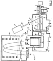
- FIG. 2 shows a preferred embodiment of a MALDI-TOF mass spectrometer 10 according to the present invention.
- the spectrometer 10 includes a conventional MALDI target probe 11, a shaft seal chamber 12, pumped in known manner, and a target installed in the target-holing electrode 13.
- a mixture of the sample to be investigated and a suitable matrix is applied to the sample probe following the usual procedure for preparing MALDI targets.
- a pulsed laser 14 is focused on the target surface 15 by lens 16, and passes through a window 17.
- the laser beam is indicated at 20, and the laser is run at a repetition rate of anywhere from below a few Hz to tens of kHz, more specifically in this embodiment tested at a rate of 13 Hz.
- An inlet 18 is provided for nitrogen or other neutral gas.
- Each laser shot produces a plume or neutral and charged molecules. Ions of the sample analyte are produced and entrained in the plume which expands into vacuum chamber 30, which contains two quadrupole rod sets 31 and 32. Chamber 30 is pumped by a pump (not shown) connected to port 34 to about 70 mTorr (approx. 9.33 N/m 2 ) but the pressure can be varied over a substantial range by adjusting the flow of gas through a controlled leak valve 18. Pressures of up to 1 atmosphere (1.013 x 10 5 N/m 2 ) could also be used in the ion generation region, by putting the ionization region in a chamber which is upstream of chamber 30, and providing a small aperture through which ions are pulled into chamber 30.
- a total length ⁇ pressure value of at least 10.0 mTorr-cm (approx. 1.33 N/m 2 -cm) could be used, although a value of 22.5 mTorr-cm (approx. 3.0 N/m 2 -cm), as in U.S. patent 4,963,736 , is preferred.
- the gas in chamber 30 typically nitrogen or argon or other suitable gas, preferably an inert gas
- a damping gas or cooling gas or buffer gas will be referred to as a damping gas or cooling gas or buffer gas.
- the quadrupole rod sets 31 and 32 were made of rods 4.45 cm in length and 11 mm in diameter, and were separated by 3 mm, i.e. the spacing between rods on adjacent corners of the rod set.
- the quadrupoles 31 and 32 are driven by a power supply which provides operating sine wave frequencies from 50 Hz to 2 MHz, and output voltages from 0 to 1000 volts peak-to-peak. Typical frequencies are 200 kHz to 1 MHz, and typical voltage amplitudes are 100 to 1000 V peak-to-peak.
- Both quadrupoles are driven by the same power supply through a transformer with two secondary coils. Different amplitudes may be applied to the quadrupoles by using a different number of turns in the two secondary coils.
- D.C. Bias or offset potentials are applied to the rods of quadrupoles 31 and 32 and to the various other components by a multiple-output power supply.
- the RF quadrupoles 31 and 32, with the damping gas between their rods can be run in an RF-only mode, in which case they serve to reduce the axial energy, the radial energy, and the energy spreads, of the ions which pass through it, as will be described. This process substantially spreads the plume of ions out along the ion path, changing the initial beam, pulsed at about 13 Hz, into a quasi-continuous beam as described in more detail below.
- the first quadrupole 31, can also be run in a mass-filtering mode by the application of a suitable DC voltage.
- the second quadruple 32 can then be used as a collision cell (and an RF-guide) in collision-induced dissociation experiments (see below).
- the ions pass along an ion path 27 and through a focusing electrode 19 and then pass through orifice 38, into a vacuum chamber 40 pumped by a pump (not shown) connected to a port 42. There, the ions are focused by grids 44 through a slot 46 into an ion storage region 48 of a TOF spectrometer generally indicated at 50.
- ions are extracted from the storage region 48 and are accelerated through a conventional accelerating column 51 which accelerates the ions to an energy of approximately 4000 electron volts per charge (4 keV).
- the ions travel in a direction generally orthogonal to the ion path 27 between the ion storage region, through a pair of deflection plates 52.
- the deflection plates 52 can serve to adjust the ion trajectories, so that the ions are then directed toward a conventional electrostatic ion mirror 54, which reflects the ions to a detector 56 at which the ions are detected.
- the ions are detected using single-ion counting and recorded with a time-to-digital converter (TDC).
- TDC time-to-digital converter
- the accelerating column 51, plates 52, mirror 54 and detector 56 are contained in a main TOF chamber 58 pumped to about 2 x 10 -7 Torr) (2.67 x 10 -3 N/m 2 ) by a pump (not shown) connected to a port 60.
- orthogonal-injection of MALDI ions from source 13 into the TOF spectrometer 50 has some potential advantages over the usual axial injection-geometry. It serves to decouple the ion production process from the mass measurement to a greater extent than is possible in the usual delayed-extraction MALDI. This means that there is greater freedom to vary the target conditions without affecting the mass spectrum, and the plume of ions has more time to expand and cool before the electric field is applied to inject them into the spectrometer. Some improvement in performance might also be expected because the largest spread in velocities is along the ejection axis, i.e. the ion path 27, normal to the target, which in this case is orthogonal to the TOF axis.
- orthogonal injection of MALDI ions into the TOF 50 without collisional cooling has several problems which appear to make the geometry impractical, namely:
- the well-defined target-plane perpendicular to the TOF axis allows a combination of time-lag focusing (delayed extraction with optimized values of delay and applied voltage) and electrostatic focusing (optimized value of the reflector voltage) in an ion mirror to produce resolution well above 10,000 in some cases.
- Figure 3 shows a spectrum of an equimolar mixture of several peptides and proteins from mass 726 to 5734 Da in an ⁇ -cyano-4-hydroxy cinnamic acid matrix. The spectrum was acquired in a single run and shows uniform mass resolution (M/ ⁇ M FWHM ) of about 5000 throughout the mass range. Using a simple external calibration with substance P and melittin, the mass determination for each of the molecular ions is accurate within about 30 ppm.
- the peaks for the various substances are identified as: peak 60 for Leucine-enkephalin; peak 61 for substance P; peak 62 for Melittin; peak 63 for CD4 fragment 25-28; and peak 64 for insulin. All peaks are identified both on the overall spectrum and as an enlarged partial spectrum.
- the resolution demonstrated in Figure 3 is rather close to the resolution obtainable with the same instrument using an ESI source.
- the entrance orifice was made slightly larger than normally used in ESI, approximately 1 mm diameter as compared to a normal diameter of around 1/3 mm, to make adjustments easier in the preliminary experiments. This does not appear to have been necessary so it is reasonable to expect improved resolution if a smaller orifice is used. Resolution up to 10,000 has been obtained with ESI ions in the same instrument and in the MALDI-QqTOF instrument described below.
- the decreasing relative intensity of the molecular ions with mass is to some extent a reflection of the decreasing detection efficiency with increasing mass. Detection efficiency depends strongly on velocity, which decreases with mass for singly-charged ions at a given energy. In this embodiment the energy of singly-charged ions is only about 5 keV (compared to 30 keV in typical MALDI experiments), so the detection efficiency limits the practical range of application to less than about 6000 Da.
- the relative intensities of the molecular ion peaks in Fig. 3 is consistent with that observed from the same sample when analyzed in a conventional MALDI experiment using 5 kV acceleration.
- the detection efficiency in the present embodiment can be increased by increasing the voltage which accelerates the ions into the spectrometer, or by increasing the voltage on the detector.
- the collisional cooling spreads the ions out along the ion beam axis changing the initial beam pulsed at 13 Hz into a quasi-continuous beam.
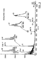
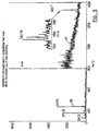
- Figure 4 shows the count rate as a function of time after the laser pulse; i.e. the distribution of transit times through the ion guide.
- the width of the time distribution is on the order of 20 ms which represents an increase in the time spread by a factor of at least 10 7 as each laser pulse is about 2 ns long. It will be appreciated that it is not necessary to produce a time distribution of the order of 20 ms; for example the quasi-continuous pulse could be as short as 0.1 ms.
- Dispersion along the axis is a disadvantage in orthogonal-injection MALDI without cooling, but with the present invention, since optimum extraction conditions do not depend on the time delay after the laser shot, multiple injection pulses into the TOF storage region 48 can be used for each laser shot. In the present embodiment, 256 injection pulses into the TOF storage region 48 were used for every laser shot. The losses are then determined by the duty cycle of the instrument which in this case is about 20%.
- the duty cycle is the percentage of the time that ions can be injected from the storage region into the TOF spectrometer; here, it effectively means the fraction of the time, the TOF storage region 48 is available to accept ions.
- a quasi-continuous beam is in fact an advantage in this mode of operation.
- ions are ejected from the target probe with every laser shot at a repetition rate of 13 Hz, but as a result of spreading along the beam axis or ion path 27 (and some losses) approximately 2 to 5 ions are injected into the instrument with every injection pulse less than one ion on average of a particular species.
- TDC Time to Digital Converter
- single-ion counting eliminates problems with detector shadowing from intense matrix peaks, and problems with peak saturation which require attention in conventional MALDI because of the strong dependence of the signal on laser fluence and the shot-to-shot variation.
- single-ion counting places much more modest demands on the detector and amplifier time resolution because the electronic reduction and digitization of the pulse is quite insensitive to the detector pulse shape.
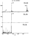
- FIG 4 four graphs are shown of the count rate against time, for leucine-enkephalin shown at 70, substance P shown at 72, Melittin shown at 74 and insulin shown at 76. Additionally, for each of these substances, graphs or spectra 71, 73, 75 and 77, are inserted showing normal TOF spectra, similar to Figure 3 .
- the transmission efficiency of the RF-quadrupole is in the range of 10 %. Taking account of the duty cycle, about 2 % of the ions produced at the target are detected in the mass spectrometer. This represents significant losses compared to the conventional axial MALDI experiment in which transmission is probably 50% or more. However, from the point of view of data rate, the losses can be compensated to a large extent by the higher repetition rate and higher fluence of the laser. In these experiments, the repetition rate was 13 Hz, but can easily be increased to 20 Hz with the current laser, or in principle up to at least 100 Hz before the counting system becomes saturated.
- the usual MALDI experiment is run at about 1 or 2 Hz.
- the laser fluence in a conventional MALDI experiment must be kept close to threshold to achieve the best performance, the threshold being the minimum energy necessary to cause vaporization of the sample to produce a useful signal using a conventional transient recording with analog to digital conversion.
- the laser fluence can be increased to the fluence at which the ion production process saturates.
- the quadrupole serves to smooth out the ion burst produced by the laser, a short intense burst of ions can be accepted. From the point of view of absolute sensitivity, it seems that the independence of the spectrum on laser conditions (see below) allows more efficient usage of the sample deposited on the target.
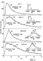
- FIG. 5 shows that the practical sensitivity achieved with substance P is in the same range as that obtainable with conventional MALDI.
- Five femtomoles of substance P were applied to the target using 4HCCA as the matrix.
- the left hand side of the spectrum is indicated at 80, and the right hand side is shown enlarged by a factor of 44 as indicated at 81.
- a portion of this spectrum is shown enlarged at 82 showing the molecular ion (MH + ).
- Figure 6 shows the spectrum 85 obtained from a tryptic digest of citrate synthase again showing the uniform mass resolution over the mass range; the inset 86 shows the spectrum obtained from 20 fmoles applied to the target.
- the laser is simply set to maximum fluence (several times the usual threshold) and left while the target is moved to a fresh position occasionally. This means that alternative targets can easily be tried (including insulating targets), and alternative lasers with different wavelengths or pulse widths can be used.
- the decoupling of the ion production from the mass measurement also provides an opportunity to perform various manipulations of the ions after ejection but before mass measurement.
- One example is parent ion selection and subsequent fragmentation (MS/MS). This is most suitably done with an additional quadrupole mass filter as described below, but even in the present embodiment of Figure 2 , some selectivity and fragmentation is possible.
- Figures 7A, 7B and 7C show three different modes of operation of the instrument shown in Figure 2 .
- the reference numerals of Figure 2 are provided along the z axis to indicate correspondence between potential level and the different elements of the apparatus.
- Voltages for the quadrupole sections 31, 32 are indicated respectively at U 1 (t) and U 2 (t).
- Figure 7A shows the simple collisional ion guide mode that was used in obtaining the results shown in Figures 4-6 .
- the same amplitudes of RF voltage and no DC offset voltages are applied to different sections of the quadrupole. Potential differences in the longitudinal direction are kept small to minimize fragmentation due to CID.
- Figure 7B shows a mass filtering mode, which is analogous to the same filtering mode implemented in conventional quadrupole mass filters.
- a DC offset voltage V is added to the first section of the quadrupole to select an ion of interest, while the second section again acts as an ordinary ion guide since there is no CID because of the small potential difference between the sections.
- the amplitude of the voltage applied in the second quadrupole section 32 is only one third of the voltage applied in the first section 31.
- Figure 7C is an MS-MS mode which differs from the mode of Figure 7B by a higher potential difference between the quadrupole sections 31,32, so ions are accelerated in that region and enter the second section with high kinetic energy, the additional energy being indicated as ⁇ collision energy.
- the second section acts as an collision cell and parent ions are decomposed there by collisions with the buffer gas (CID).
- the amplitude of the RF voltage in the second section is only one third of the amplitude of the RF voltage in the first section, which allows daughter ions much lighter than the parent ions to have stable trajectories and to be transmitted through the second quadrupole.
- Figure 8 shows examples of the spectra obtained in the different modes illustrated in Figure 7 , and in particular gives an example of possible beam manipulation. All the spectra were acquired using the same initial sample.
- Figure 8A is a mass spectrum where ions were cooled in a collisional focusing ion guide (the mode of Figure 7A ).
- Figure 8B is an example where ions of interest were selected in the first quadrupole 31 and cooled in the second quadrupole 32 section (the mode of Figure 7B ). Once ions of interest have been selected, they can be used for fragmentation in CID to obtain detailed information on composition and structure.
- Figure 8C presents an MS/MS spectrum of substance P obtained in this way.
- Molecular ions of substance P are selected in the first quadrupole section and fragmented by collisions in the second quadrupole section (according to the mode of Figure 7C ).
- the potential difference, ⁇ collision energy, between the first and second quadrupoles was 100V.
- the intensities of the fragment ions were small in comparison with intensity of the primary ion so the region inside dotted lines is expanded by a factor of 56.
- Figure 8D shows the spectrum obtained in the same mode but where the potential difference between the quadrupoles 31, 32 was 150 V. In this case, more fragment ions are observed and the parent ion peak is substantially reduced.
- Figure 9 shows how long a signal from the same spot on a MALDI target can last.
- a given spot was irradiated by a series of shots from the laser, running at 13 Hz.
- the laser intensity was two or three times the "threshold" intensity.
- the sample lasted for about one minute.
- the shape of the curve suggests that the laser shots dig deeper and deeper into the sample until it is exhausted. At that point the laser irradiates the metallic substate, so no signal is observed.
- the present invention enables two such sources to be available in one instrument.
- the MALDI probe 11 in Figure 2 can be replaced by an ESI source to enable measurement of ESI spectra in the instrument.
- the instrument would then be essentially the same as the one illustrated in the paper Krutchinsky A.N., Loboda A.V., Spicer V.L., Dworschak R., Ens W., Standing K.G., Rapid Commun. Mass Spectrom. 1998,12, 508-518 .
- This change could of course be carried out by actually taking off one source and replacing it by the other, but a number of more convenient arrangements can be provided.
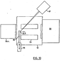
- FIG 10 shows a further embodiment where the electrospray ion source 94a is attached to the input of a collisional damping interface 92, including a quadrupole, or other multipole, rod set 93.
- a MALDI ion source 94b is introduced on a probe 95 that enters from the side, and can be displaced in and out; for this purpose, a shaft end 96 is slidingly and sealingly fitted into the housing of the collisional interface 92.
- the MALDI ion source 94b is similar to the one shown in Figure 2 except in this case the sample is deposited onto a flat surface machined on the side of the probe shaft 95, instead of onto the end of a cylindrical probe.
- the sample is irradiated by a laser with corresponding optics, generally indicated at 97, and ions are transmitted to a spectrometer indicated at 98.
- a laser with corresponding optics, generally indicated at 97
- ions are transmitted to a spectrometer indicated at 98.
- shaft 96 is pulled out far enough to clear the path of the ESI ions.
- the MALDI ion source 94b is operating the shaft 96 is inserted back so the MALDI target 94b is in the central position.
- MALDI and ESI techniques are often considered to be complementary methods for biochemical analysis, so many biochemical or pharmaceutical laboratories have two instruments in use.
- the cost of a combined instrument is expected to be little more than half the cost of two separate instruments.
- similar procedures for ion manipulation, detection and mass calibration could be used, since the ion production is largely decoupled from the ion measurement. This would simplify the analysis and processing of the separate spectra and their comparison.
- the apparatus could include a single multipole rod set as shown in Figure 1 , or two rod sets as shown in Figure 2 . While quadrupole rod sets are preferred, other rod sets, such as hexapole and octopole are possible, and the rod set can be selected based on the known characteristics of the different rod sets. Additionally, it is possible that three or more rod sets could be provided. Further, while Figure 2 shows the two rod sets, 31 and 32 provided in a common chamber, the rod sets could, in known manner, be provided in separate chambers operating at different pressures, to enable different operations to be preformed.
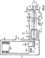
- the MALDI target is provided at 100 and generates an ion beam indicated at 102.
- the MALDI target 100 is located in a differentially pumped chamber 104 connected to a pump as indicated at 106 in known manner.
- a first rod set Q0 is located in the chamber 104.
- An aperture and an interquad aperture plate 108 provides communication through to a main chamber 110. Again, in known manner a pump connection is provided at 112.
- a short rod set 111 within the main chamber 110, there is a short rod set 111, sometimes referred to as “stubbies", provided for the purpose collimating the beam.
- a first quadrupole rod set in the chamber 110 is indicated at Q1 and a second rod set at Q2.
- the rod set Q2 is located in a collision cell 114 provided with a connection, indicated at 116, for a collision gas.
- ions pass through a grid and then an aperture into the storage region 48 of the TOF instrument, again indicated at 50.
- a TOF instrument 50 is provided with a liner 118 around the flight region.
- the differentially pumped chamber 104 is maintained at pressure of around 10 -2 torr.
- the main chamber 110 is maintained at a pressure of around 10 -5 torr, while the collision cell 114 is maintained at a pressure of around 10 -2 torr.
- the pressure in the collision cell 114 can be controlled by controlling the supply of nitrogen to it through connection 116.
- collisional damping of ions generating from the MALDI target 100 is accomplished by the relatively high pressure in the differentially pumped chamber 104. Ions then pass through into the quadrupole rod set Q1, which can be operated to mass select a desired ion.
- the mass selected ion is then passed to the collision cell 114, and the rod set Q2; potentials are such that ions enter the rod set Q2 with sufficient energy to effect collision induced dissociation.
- the fragment ions generated by this CID are then passed into the TOF instrument 50 for analysis.
- Typical spectra obtained in a MALDI-QqTOF instrument are presented in Figure 12 .
- the spectrum shown in Fig. 12a was obtained when Q1 was operated in a wide band mode, so all ions produced in the MALDI ion source were delivered to the TOF mass analyzer.
- Three peaks (121, 122, 123) in Fig 12a correspond to ions of leucine-enkephalin, substance P and mellitin respectively.
- Q1 is operated in selection mode, the spectrum shown in Fig 12b is observed.
- Q1 was set to select only ions of substance P (peak 122) located at m/z around 1347.7. Note that no other peaks or background were observed in the mass spectrum, as conditions in Q1 prevented transmission of other ions.
- Figure 12c shows the result of selection at substance P (peak 122) and collisional induced dissociation of the substance P ions.
- Q1 was set to selection mode as in Fig 12b but the potential difference between Q0 and Q2 was increased to promote CID.
- the peaks observed in the lower mass region are fragments of the substance P ions.
- the MALDI source is indicated at 130 and the ion beam at 132.
- a sampling cone 134 was placed between the MALDI source 130 and the rod set Q0. This effectively separates the differentially pumped region into a first differentially pumped region 136 and a second differentially pumped region 138.
- These differentially pumped regions 136, 138 are provided with respective connections 137 and 139 to pumps.
- a short set of rods or stubbies 140 together with a rod set Q1 are provided in a chamber here indicated at 142.
- the alternative collisional damping setup of Figure 13 has been implemented in MALDI-QqTOF instrument but can be used with any configuration of collisional RF ion guides such as the simpler geometry described earlier and shown in Figure 2 .
- some collisional damping is accomplished in the first region or chamber 136 where almost no RF field is present.
- Nitrogen is supplied to this chamber 136, as in Figure 2 , and is also supplied to the chamber 104 in Figure 11 ; this is comparable to Figure 2 , although the nitrogen connection is not shown in these later figures.
- the pressure in this first differentially pumped region or chamber 136 is typically higher than in the second differentially pump chamber 138 and ions are dragged towards the entrance of Q0 by the combination of a DC field and the gas flow.
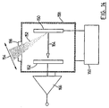
- FIG 14 shows an apparatus used to study the effect of pressure and electric field on the intensity of the signal produced by MALDI.
- MALDI ions are generated at a target 150 by a pulsed UV-laser beam 152.
- the laser beam 152 passed through a lens 154 and a window 156, as in the spectrometer configurations described above.
- the window 156 is provided i n a chamber 158, whose internal pressure can be varied in known manner (connections for pumps, etc. are not shown).
- a potential difference U between the target 150 and a collector electrode 162 is provided by a power supply 160.
- ions generated at the target 150 travel, as indicated at 164, to the collector electrode 162.
- An approximately homogeneous electric field is established in the region between the target 150 and the collector electrode 162.
- the field strength is proportional to the applied potential difference U.
- the distance between the target and collector was about 3 mm.
- the laser was operated at 20 Hz and the total ion current was measured using an amplifier 166.
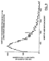
- Figure 15 shows the dependence of the total ion current produced by MALDI at different pressures inside the chamber 158 as a function of the voltage applied between the target 150 and the collector electrode 162 shown in Fig. 14 . It is apparent that ion yield decreases with increasing pressure, and there is a significant drop in yield between 14 and 47 Torr. However, the drop in yield can be recovered by raising the electric field strength.
- the MALDI technique can be used at any desirable pressure, even out of the range in which RF collisional multipoles can be implemented. Collisional damping of the ions can be accomplished at least partially in the region with no RF field adjacent to the sample target. The inventors believe that similar dependence of pressure and electric field can be observed in some other pulsed ion sources and these ionization techniques can be also used with collisional damping at higher pressures.
Abstract
Description
- This invention relates to mass spectrometers and ion sources therefor. More particularly, this invention is concerned with pulsed ion sources and the provision of a transmission device which gives a pulse ion source many of the characteristics of a continuous source, such that it extends and improves the application of Time of Flight Mass Spectrometry (TOFMS) and that it additionally can be used with a wide variety of other spectrometers, in addition to an orthogonal injection time-of-flight mass spectrometer.
- Ion sources for mass spectrometry may be either continuous, such as ESI (electrospray ionization) sources or SIMS (secondary ion mass spectrometry) sources, or pulsed, such as MALDI (matrix-assisted laser desorption/ionization sources). Continuous sources have normally been used to inject ions into most types of mass spectrometer, such as sector instruments, quadrupoles, ion traps and ion cyclotron resonance spectrometers. Recently it has also become possible to inject ions from continuous sources into time-of-flight (TOF) mass spectrometers through the use of "orthogonal injection", whereby the continuous beam is injected orthogonally to the main TOF axis and is converted to the pulsed beam required in the TOF technique. This is most efficiently carried out with the addition of a collisional damping interface between the source and the spectrometer, and this is described in the following paper, having four authors in common with the present invention (Krutchinsky A.N., Chernushevich I.V., Spicer V.L., Ens W., Standing K.G., Journal of the American Society for Mass Spectrometry, 1998, 9, 569-579).
- On the other hand, pulsed sources, MALDI sources for example, have usually been coupled directly to TOF mass spectrometers, to take advantage of the discrete or pulse nature of the source. TOF mass spectrometers have several advantages over conventional quadrupole or ion trap mass spectrometers. One advantage is that TOF mass spectrometers can analyze a wider mass-to-charge range than do quadrupole and ion trap mass spectrometers. Another advantage is that TOF mass spectrometers can record all ions simultaneously without scanning, with higher sensitivity than quadrupole and ion trap mass spectrometers. In a quadrupole or other scanning mass spectrometer, only one mass can be transmitted at a time, leading to a duty cycle which may typically be 0.1%, which is low (leading to low sensitivity). A TOF mass spectrometer therefore has a large inherent advantage in sensitivity.
- However, TOF mass spectrometers encounter problems with many widely used sources which produce ions with a range of energies and directions. The problems are particularly acute when ions produced by the popular MALDI (matrix-assisted laser desorption/ionization) technique are used. In this method, photon pulses from a laser strike a target and desorb ions whose masses are measured in the mass spectrometer. The target material is composed of a low concentration of analyte molecules, which usually exhibit only moderate photon absorption per molecule, embedded in a solid or liquid matrix consisting of small, highly-absorbing species. The sudden influx of energy is absorbed by the matrix molecules, causing them to vaporize and to produce a small supersonic jet of matrix molecules and ions in which the analyte molecules are entrained. During this ejection process, some of the energy absorbed by the matrix is transferred to the analyte molecules. The analyte molecules are thereby ionized, but without excessive fragmentation, at least in the ideal case.
- Because a pulsed laser is normally used, the ions also appear as pulses, facilitating their convenient measurement in a time-of-flight spectrometer. However, the ions acquire a considerable amount of energy in the supersonic jet, with velocities of the order of 700 m/s, and they also may lose energy through collisions with the matrix molecules during acceleration, particularly in high accelerating fields. These and similar effects lead to considerable peak broadening and consequent loss of resolution in a simple linear time-of-flight instrument, where the ions are extracted from the target nearly parallel to the spectrometer axis. A partial solution to the problem is provided by a reflecting spectrometer, which partially corrects for the velocity dispersion, but a more effective technique is the use of delayed extraction, either by itself or in combination with a reflector. In delayed extraction, the ions are allowed to drift for a short period before the accelerating voltage is applied. This technique partially decouples the ion production process from the measurement, making the measurement less sensitive to the detailed pattern of ion desorption and acceleration in any particular case. Even so, successful operation requires careful control of the laser fluence (i.e. the amount of power supplied per unit area) and usually some hunting on the target for a favorable spot. Moreover, the extraction conditions required for optimum performance have some mass dependence; this complicates the calibration procedure and means that the complete range of masses cannot be observed with optimum resolution at any given setting. Also, the technique has had limited success in improving the resolution for ions of masses greater than about 20,000 Da. Moreover, it is difficult to obtain high performance MS-MS data in conventional MALDI instruments because ion selection and fragmentation tend to broaden the fragment peak width. The present inventors have realized that these problems can be overcome by abandoning the attempt to maintain the original pulse width, producing instead a quasi-continuous beam with superior characteristics, and then pulsing the injection voltage of the TOF device at an independent repetition rate.
- Although coupling to a TOF instrument is used as an example above, problems also arise in coupling MALDI and other pulsed sources to other types of mass spectrometer, such as quadrupole (or other multipole), ion trap, magnetic sector and FTICRMS (Fourier Transform Ion Cyclotron Resonance Mass Spectrometer). Further, it is also desirable to be able to couple MALDI or other pulsed sources to tandem mass spectrometers, e.g. a triple quadrupole or a quadrupole TOF hybrid instrument, which allows MS/MS of MALDI ions to be obtained. Standard MALDI instruments cannot be configured to carry out high performance MS/MS. The dispersion in energy and angle of ions produced by a MALDI source, or similar source, accentuates the difficulty of ion injection. Also, because the residence times of ions in most other types of mass spectrometer are considerably longer than in TOF instruments, the large space charge in the pulse can introduce additional problems. These instruments are all designed to operate with continuous sources, so conversion of the pulsed source to a quasi-continuous one solves most of the problems.
-
German Patent DE 19511333 (corresponding to published British applicationGB 2,299,446A ion trap 12. Theion trap 12 serves to confine the ions in a configuration suitable for outpulsing into the flight tube of a time-of flight section. There is no teaching or suggestion that a pulse source could be used. -
US 5,373,156 discloses a method and device for the mass-spectrometric examination of organic ions. Aneodymium YAG laser 1 produces a light pulse lasting about 10 microseconds. A focal point is produced on one side of a foil 4, which is covered on the opposite side with a thin application of the substance under examination. The ions shaken off the foil are decelerated in a friction chamber 23 due to collisions with hydrogen atoms acting as a friction gas and admitted into the friction chamber 23 via inlets 5 and 7. Askimmer 10 feeds the slowed ions to the skimmer opening, the ions then being carried along into the next chamber 24. The ions are then directed into the chamber of the mass spectrometer by the potential of askimmer 15. An ion-optical lens 17 delays the ions and focuses them on the inlet opening of an RFquadrupole ion trap 18, where the ions are slowed by a damping gas and caught. For examination of the ions, the ion trap is operated with a scanning method in which the ions are ejected mass-sequentially through holes in an end cap. The ejected ions are measured with anion detector 19. -
US 5,689,111 discloses an ion storage time-of-flight mass spectrometer comprising a continuously operatingion source 10. The ions are introduced into a firststage pumping region 20, formed into a beam by a multipole ion guide and collimated and transferred into thepulsing region 26 of the time-of-flight mass analyzer. The mass analyzer is operating in an orthogonal injection mode and employs a pulsed electric field between a repeller lens 23 and a draw-out lens 24. The pulsed electric field establishes the start time for the measurement of the flight time distribution of the ions arriving at the detector 36, the flight time being related to the mass to charge ratios of the ions. In the continuous mode embodiment the ions emitted from theion source 10 are directly fed through the ion guide into the time-of-flight mass analyzer. In the storage mode embodiment, on the other hand, the ions are first stored in the ion guide by means of a potential well in the longitudinal direction of the ion guide and then emitted from the ion guide into the time-of-flight mass analyzer by switching for a short duration the voltage on theexit electrode 15 thereby creating a leak of the potential well. After a variable delay t2 the electric field inregion 26 of the mass analyzer is pulsed for a short period of time by the repeller plate 23 to accelerate the ions perpendicular to their original direction towards the flight tube 35 to be detected for mass analysis. - Accordingly, it is desirable to provide an apparatus and method enabling a pulse source, such as a MALDI source, to be coupled to a variety of spectrometer instruments, in a manner which more completely decouples the spectrometer from the source and provides a more continuous ion beam with smaller angular and velocity spreads.
- More particularly, it is desirable to provide an improved TOF mass spectrometer with a pulsed ion source, in which the energy spread in the ion beam is reduced, in which the source is more completely decoupled from the spectrometer than in existing instruments, in which problems resulting from ion fragmentation are reduced, enabling new types of measurement, and in which the results obtained from the mass spectrometer and its ease of operation are consequently improved.
- It is also desirable to provide a TOF mass spectrometer with both continuous and pulsed sources, for example both ESI and MALDI sources, so either source can be selected.
- In accordance with the present invention, there is provided a mass spectrometer system according to
claim 1. - As time of flight mass spectrometers require a pulsed beam, conventional teaching is that a pulsed source should be coupled maintaining the pulsed characteristics. However, the present inventors have now realised that there are advantages to, in effect converting a pulsed beam into a continuous, or at least quasi-continuous, beam, and than back into a pulsed beam. The advantages are: improvement in beam quality through collisional damping; decoupling of the ion production from the mass measurement; ability to measure the beam current by single-ion counting because it is converted from a few large pulses to many small pulses, for example from about 1 Hz. to about 4 kHz., or a factor of 4,000; compatibility with a continuous source, such as ESI, offering the possibility of running both sources on one instrument.
- Preferably, the ion source provides the analyte for ionization by radiation, and there is provided a source of electromagnetic radiation, more preferably a pulsed laser, directed at the ion source, for generating radiation pulses to cause desorption and ionization of analyte molecules.
- Advantageously, the ion source comprises a target material composed of a matrix and analyte molecules in the matrix, the matrix comprising a species adapted to absorb radiation from the radiation source, to promote desorption and ionization of the analyte molecules.
- Preferably, the transmission device comprises a multipole rod set. There can be two or more multipole rod sets and means for supplying different RF and DC voltages to the rod sets.
- Collisional damping can also be accomplished in a chamber where no RF field is present providing there is enough buffer gas pressure. In this case ions with reduced velocities can be moved to the exit of the chamber by gas flow drag or a DC electrostatic field. Combinations of electrostatic fields, RF fields and gas flow can also be implemented in a collisional damping chamber.
- Another advantage of the invention is that the collisional cooling of the ions helps to reduce the amount of fragmentation of the molecular ions. It is usually desirable to produce a simple mass spectrum containing only ions representative of molecular species. In typical MALDI ion sources, therefore, the laser power must be carefully optimized so that it is close to the threshold of ionization in order to reduce fragmentation. The inventors have observed, however, that the presence of a gas around the sample surface greatly assists in reducing fragmentation, even at relatively high laser power. Presumably this is due to the effect of collisions with gas molecules which remove internal energy from the desorbed species before they can fragment. This means that the laser power can be increased in order to improve the ion signal strength, without causing excessive decomposition.
- The inventors have observed that the amount of fragmentation is decreased as the pressure is increased up to at least approximately 1 torr (approx. 130 N/m2). Higher pressures may be even more advantageous, but electric fields may be required to avoid clustering reactions at higher pressure.
- The mass spectrometer system can include a continuous ion source, and means for selecting one of the pulsed ion source and the continuous ion source, and this then provides the characteristics of two separate instruments in one instrument. The two ion sources can comprise a MALDI source and an ESI source.
- Another aspect of the present invention provides a method according to claim 23.
- The gas pressure of the damping gas can be in the range from about 10-4 Torr (approx. 0.013 N/m2) up to at least 760 Torr (approx. 1.013 x 10⁵ N/m2). Preferably, step (3) comprises providing an RF rod set within the transmission device. Further, a DC field can be provided between the ion source and the spectrometer to promote movement of ions towards the spectrometer.
- The method can include providing two or more rod sets in the ion transmission device, and operating at least one rod set with a DC offset to enable selection of ions with a desired mass-to-charge ratio. A potential difference can be provided between two adjacent rod sets sufficient to accelerate ions into the downstream rod set, to cause collisionally induced dissociation in the downstream rod set.
- When a pulsed laser is used, for each laser pulse, a plurality of pulses of ions are delivered into the time-of-flight mass spectrometer.
- The ions can first pass through one or more differentially pumped regions that provide a transition from the pressure at the ion source to pressure in the spectrometer. The ion source may be at atmospheric pressure or at least at a pressure substantially higher than that in downstream quadrupole stages and in the mass spectrometer. At least one of these regions can be without any rod set and ion motion towards the mass spectrometer is then driven by gas flow and/or an electrostatic potential.
- For a better understanding of the present invention and to show more clearly how it may be carried into effect, reference will now be made, by way of example, to the accompanying drawings, which show preferred embodiments of the present invention and in which:
-
Figure 1 shows a block diagram of a mass spectrometer system; -
Figure 2 is a schematic diagram showing a MALDI-TOF mass spectrometer with orthogonal injection of the MALDI ions into the spectrometer through a collisional damping interface (quadrupole ion guide) according to the present invention; -
Figure 3 shows a mass spectrum of a mixture of several peptides and proteins leucine-enkephalin-Arg (Le-R), substance P (Sub P), melittin (ME), CD4 fragment 25-58 (CD4), and insulin (INS)) produced in the spectrometer ofFigure 2 ; -
Figure 4 shows plots of transit times through the interface for different ions; -
Figure 5 shows a mass spectrum of substance P; -
Figure 6 shows a mass spectrum of a tryptic digestion of citrate synthase; -
Figure 7A shows a schematic of part of spectrometer ofFigure 2 , showing the collisional interface and indicating applied voltages; -
Figures 7B, 7C and 7D show different operating regimes of the mass spectrometer ofFigure 2 ; -
Figures 8A, 8B, 8C, and 8D are mass spectra obtained from substance P recorded in the different operation regimes, according toFigures 7B, 7C , and 7D; -
Figure 9 shows the behaviour of the ion current from a single target spot as a function of time; and -
Figure 10 shows schematically combined ESI and MALDI sources for a mass spectrometer. -
Figure 11 shows a MALDI-QqTOF mass spectrometer utilizing a collisional damping interface including extra ion manipulation stages which are added between the interface and the time-of-flight mass spectrometer; -
Figure 12 shows mass spectra obtained on a MALDI-QqTOF ofFigure 11 in a single MS and MS-MS modes; -
Figure 13 shows an alternative collisional damping setup for the MALDI-QqTOF mass spectrometer ofFigure 11 , where ion velocities are partially damped in a region without RF fields; -
Figure 14 shows an experimental apparatus which was used to investigate the effect of pressure and electric field strength on the MALDI ion current; and -
Figure 15 is a graph showing the total ion current produced by MALDI source shown inFigure 14 as a function of voltage difference applied at different pressures in the chamber. - The first embodiment shown in
Figure 1 is a block diagram of a general mass spectrometer system. Here 1 represents any sort of pulsed ion source (for instance MALDI), 2 is a collisional focusing chamber or region filled with a buffer gas and with a multipole 3 driven at some RF voltage. This is followed by an optional manipulation stage 4 and then a mass analyzer 5. The collisional ion guide 3, in accordance with the present invention, spreads the pulsed ion beam in time, and improves its beam quality (i.e. space and velocity distributions) by damping the initial velocity and focusing the ions toward the central axis. The beam is then quasi-continuous and may enter an optional manipulation stage 4, where ions can be subjected to any sort of further manipulation. Finally the resultant ions are analyzed in the mass analyzer 5. - A simple example of further manipulation in stage 4 is dissociation of the ions by collisions in a gas cell, so that the resulting daughter ions can be examined in the mass analyzer. This may be adequate to determine the molecular structure of a pure analyte. If the analyte is a complex mixture, stage 4 needs to be more complicated. In a triple quadrupole or a QqTOF instrument (as disclosed in A. Shevchenko et al, Rapid Commun. Mass Spectrom. 11, 1015, (1997)), stage 4 would include a quadrupole mass filter for selection of a parent ion of interest and a quadrupole collision cell for decomposition of that ion by collision-induced dissociation (CID). Both parent and daughter ions are then analyzed in section 5, which is a quadrupole mass filter in the triple quadrupole, or a TOF spectrometer with orthogonal injection in the QqTOF instrument. In both cases stages 1 and 2 would consist of a pulsed source and a collisional damping ion guide.
- It will be appreciated that the collisional focusing chamber 2 is shown with a multipole rod set 3, which could be any suitable rod set, e.g. a quadrupole, hexapole or octopole. The particular rod set selected will depend upon the function to be provided.
- Alternatively, a radio frequency ring guide could be used for the collisional focusing device, and ion creation could be performed within the volume defined by the radio frequency field in order to contain the ions.
-
Figure 2 shows a preferred embodiment of a MALDI-TOF mass spectrometer 10 according to the present invention. Thespectrometer 10 includes a conventional MALDI target probe 11, ashaft seal chamber 12, pumped in known manner, and a target installed in the target-holingelectrode 13. A mixture of the sample to be investigated and a suitable matrix is applied to the sample probe following the usual procedure for preparing MALDI targets. Apulsed laser 14 is focused on thetarget surface 15 bylens 16, and passes through awindow 17. The laser beam is indicated at 20, and the laser is run at a repetition rate of anywhere from below a few Hz to tens of kHz, more specifically in this embodiment tested at a rate of 13 Hz. Aninlet 18 is provided for nitrogen or other neutral gas. Each laser shot produces a plume or neutral and charged molecules. Ions of the sample analyte are produced and entrained in the plume which expands intovacuum chamber 30, which contains two quadrupole rod sets 31 and 32.Chamber 30 is pumped by a pump (not shown) connected to port 34 to about 70 mTorr (approx. 9.33 N/m2) but the pressure can be varied over a substantial range by adjusting the flow of gas through a controlledleak valve 18. Pressures of up to 1 atmosphere (1.013 x 10⁵ N/m2) could also be used in the ion generation region, by putting the ionization region in a chamber which is upstream ofchamber 30, and providing a small aperture through which ions are pulled intochamber 30. Lower pressures could be used, and an important characteristic is the product of pressure and rod length. Thus, a total length × pressure value of at least 10.0 mTorr-cm (approx. 1.33 N/m2-cm) could be used, although a value of 22.5 mTorr-cm (approx. 3.0 N/m2-cm), as inU.S. patent 4,963,736 , is preferred. The gas in chamber 30 (typically nitrogen or argon or other suitable gas, preferably an inert gas) will be referred to as a damping gas or cooling gas or buffer gas. - In the embodiment tested, the quadrupole rod sets 31 and 32 were made of rods 4.45 cm in length and 11 mm in diameter, and were separated by 3 mm, i.e. the spacing between rods on adjacent corners of the rod set. The
quadrupoles quadrupoles first quadrupole 31, can also be run in a mass-filtering mode by the application of a suitable DC voltage. The second quadruple 32 can then be used as a collision cell (and an RF-guide) in collision-induced dissociation experiments (see below). - From
chamber 30, the ions pass along anion path 27 and through a focusingelectrode 19 and then pass throughorifice 38, into avacuum chamber 40 pumped by a pump (not shown) connected to aport 42. There, the ions are focused bygrids 44 through aslot 46 into anion storage region 48 of a TOF spectrometer generally indicated at 50. - In known manner, ions are extracted from the
storage region 48 and are accelerated through a conventional acceleratingcolumn 51 which accelerates the ions to an energy of approximately 4000 electron volts per charge (4 keV). The ions travel in a direction generally orthogonal to theion path 27 between the ion storage region, through a pair of deflection plates 52. The deflection plates 52 can serve to adjust the ion trajectories, so that the ions are then directed toward a conventionalelectrostatic ion mirror 54, which reflects the ions to adetector 56 at which the ions are detected. The ions are detected using single-ion counting and recorded with a time-to-digital converter (TDC). The acceleratingcolumn 51, plates 52,mirror 54 anddetector 56 are contained in amain TOF chamber 58 pumped to about 2 x 10⁻⁷ Torr) (2.67 x 10⁻³ N/m2) by a pump (not shown) connected to aport 60. - The use of orthogonal-injection of MALDI ions from
source 13 into theTOF spectrometer 50 has some potential advantages over the usual axial injection-geometry. It serves to decouple the ion production process from the mass measurement to a greater extent than is possible in the usual delayed-extraction MALDI. This means that there is greater freedom to vary the target conditions without affecting the mass spectrum, and the plume of ions has more time to expand and cool before the electric field is applied to inject them into the spectrometer. Some improvement in performance might also be expected because the largest spread in velocities is along the ejection axis, i.e. theion path 27, normal to the target, which in this case is orthogonal to the TOF axis. However, orthogonal injection of MALDI ions into theTOF 50 without collisional cooling has several problems which appear to make the geometry impractical, namely: - (1) The radial energy distribution, while much smaller than the axial energy is still sufficient to cause substantial spreading and expansion of the beam as it leaves the quadrupole rod set 32 and travels toward the TOF axis. The spatial spread of the beam along the TOF axis limits the resolution. The effect can be reduced with collimation but only at a significant sacrifice in sensitivity; a collimating slit must be placed sufficiently far from the TOF axis to avoid distorting the extraction field, and so the target must be placed far enough from the collimation slit to produce a reasonably parallel beam;
- (2) The axial velocity of the ions, i.e. velocity along the
ion path 27, in the plume is largely independent of mass which means the energy is mass dependent. Since the axial energy determines the direction of the trajectory after acceleration into the TOF spectrometer, instrumental acceptance (or acceptance by the TOF spectrometer) is mass dependent; i.e. there is mass discrimination. The same effect is observed when ESI ions are injected without collisional cooling as explained in detail in the prior publication mentioned above; and - (3) The width of the axial energy distribution is comparable in magnitude with the axial energy itself, so the beam spreads out along its axis by an amount comparable to the separation between the target and the TOF axis. The size of the aperture which admits ions from the storage region into the spectrometer must clearly be much smaller than this to maintain a uniform extraction field, particularly if a slit is placed between the target and the TOF axis. This further reduces the sensitivity.
- In delayed extraction MALDI in the usual axial geometry, i.e. not the orthogonal configuration shown, acceptance is nearly complete, and while the largest velocity spread is along the TOF axis, the well-defined target-plane perpendicular to the TOF axis allows a combination of time-lag focusing (delayed extraction with optimized values of delay and applied voltage) and electrostatic focusing (optimized value of the reflector voltage) in an ion mirror to produce resolution well above 10,000 in some cases.
- Experiments carried out by the present inventors suggest that competitive resolution could not be obtained with an acceptable signal using orthogonal injection, unless collisional cooling according to the present invention is employed. Moreover, some disadvantages of delayed-extraction MALDI -- the dependence of optimum extraction conditions on mass, and the more complex calibration required -- are still present in orthogonal injection MALDI without cooling although to a lesser extent than with axial injection.
- The introduction of an RF quadrupole or other multipole with collisional cooling of the ions between the MALDI target and the orthogonal injection geometry avoids the problems described above while offering additional advantages. These are detailed below with reference to the remaining figures.
- By reducing the radial energies of the ions, an approximately parallel beam can be produced, greatly reducing the losses that result from collimation before the ions enter the storage region. This allows the use of a larger entrance aperture to the
TOF spectrometer 50, further reducing losses. By reducing the axial energies of the ions, and then reaccelerating them to a uniform energy, the mass discrimination mentioned above is not present. - The uniform energy distributions of the ions after cooling remove any mass dependence on the optimum extraction conditions and allow the simple quadratic relation between TOF and mass to be used for calibration with two calibrant peaks.
Figure 3 shows a spectrum of an equimolar mixture of several peptides and proteins from mass 726 to 5734 Da in an α-cyano-4-hydroxy cinnamic acid matrix. The spectrum was acquired in a single run and shows uniform mass resolution (M/ΔMFWHM) of about 5000 throughout the mass range. Using a simple external calibration with substance P and melittin, the mass determination for each of the molecular ions is accurate within about 30 ppm. Here, the peaks for the various substances are identified as:peak 60 for Leucine-enkephalin;peak 61 for substance P; peak 62 for Melittin; peak 63 for CD4 fragment 25-28; and peak 64 for insulin. All peaks are identified both on the overall spectrum and as an enlarged partial spectrum. The resolution demonstrated inFigure 3 is rather close to the resolution obtainable with the same instrument using an ESI source. In the present embodiment, the entrance orifice was made slightly larger than normally used in ESI, approximately 1 mm diameter as compared to a normal diameter of around 1/3 mm, to make adjustments easier in the preliminary experiments. This does not appear to have been necessary so it is reasonable to expect improved resolution if a smaller orifice is used. Resolution up to 10,000 has been obtained with ESI ions in the same instrument and in the MALDI-QqTOF instrument described below. - The decreasing relative intensity of the molecular ions with mass is to some extent a reflection of the decreasing detection efficiency with increasing mass. Detection efficiency depends strongly on velocity, which decreases with mass for singly-charged ions at a given energy. In this embodiment the energy of singly-charged ions is only about 5 keV (compared to 30 keV in typical MALDI experiments), so the detection efficiency limits the practical range of application to less than about 6000 Da. The relative intensities of the molecular ion peaks in
Fig. 3 is consistent with that observed from the same sample when analyzed in a conventional MALDI experiment using 5 kV acceleration. The detection efficiency in the present embodiment can be increased by increasing the voltage which accelerates the ions into the spectrometer, or by increasing the voltage on the detector. - As mentioned above, the collisional cooling spreads the ions out along the ion beam axis changing the initial beam pulsed at 13 Hz into a quasi-continuous beam. This is illustrated in
Figure 4 which shows the count rate as a function of time after the laser pulse; i.e. the distribution of transit times through the ion guide. The width of the time distribution is on the order of 20 ms which represents an increase in the time spread by a factor of at least 107 as each laser pulse is about 2 ns long. It will be appreciated that it is not necessary to produce a time distribution of the order of 20 ms; for example the quasi-continuous pulse could be as short as 0.1 ms. Dispersion along the axis is a disadvantage in orthogonal-injection MALDI without cooling, but with the present invention, since optimum extraction conditions do not depend on the time delay after the laser shot, multiple injection pulses into theTOF storage region 48 can be used for each laser shot. In the present embodiment, 256 injection pulses into theTOF storage region 48 were used for every laser shot. The losses are then determined by the duty cycle of the instrument which in this case is about 20%. The duty cycle is the percentage of the time that ions can be injected from the storage region into the TOF spectrometer; here, it effectively means the fraction of the time, theTOF storage region 48 is available to accept ions. A quasi-continuous beam is in fact an advantage in this mode of operation. Approximately 104 to 106 ions are ejected from the target probe with every laser shot at a repetition rate of 13 Hz, but as a result of spreading along the beam axis or ion path 27 (and some losses) approximately 2 to 5 ions are injected into the instrument with every injection pulse less than one ion on average of a particular species. This allows single-ion counting to be used with a TDC (Time to Digital Converter), which makes the combination of high timing resolution (0.5 ns) and high repetition rate (essential for maximum duty cycle) technically much simpler than using a transient recorder which is necessary in conventional MALDI experiments. In addition, the use of single-ion counting eliminates problems with detector shadowing from intense matrix peaks, and problems with peak saturation which require attention in conventional MALDI because of the strong dependence of the signal on laser fluence and the shot-to-shot variation. Finally, single-ion counting places much more modest demands on the detector and amplifier time resolution because the electronic reduction and digitization of the pulse is quite insensitive to the detector pulse shape. - In
Figure 4 , four graphs are shown of the count rate against time, for leucine-enkephalin shown at 70, substance P shown at 72, Melittin shown at 74 and insulin shown at 76. Additionally, for each of these substances, graphs orspectra Figure 3 . - Assuming 104 ions of a single molecular ion species are produced with each laser shot, the transmission efficiency of the RF-quadrupole is in the range of 10 %. Taking account of the duty cycle, about 2 % of the ions produced at the target are detected in the mass spectrometer. This represents significant losses compared to the conventional axial MALDI experiment in which transmission is probably 50% or more. However, from the point of view of data rate, the losses can be compensated to a large extent by the higher repetition rate and higher fluence of the laser. In these experiments, the repetition rate was 13 Hz, but can easily be increased to 20 Hz with the current laser, or in principle up to at least 100 Hz before the counting system becomes saturated. In contrast, the usual MALDI experiment is run at about 1 or 2 Hz. The laser fluence in a conventional MALDI experiment must be kept close to threshold to achieve the best performance, the threshold being the minimum energy necessary to cause vaporization of the sample to produce a useful signal using a conventional transient recording with analog to digital conversion. In the present invention, the laser fluence can be increased to the fluence at which the ion production process saturates. As the quadrupole serves to smooth out the ion burst produced by the laser, a short intense burst of ions can be accepted. From the point of view of absolute sensitivity, it seems that the independence of the spectrum on laser conditions (see below) allows more efficient usage of the sample deposited on the target. Using fluence several times higher than threshold produces ions until the matrix is completely removed from the target probe.
Figure 5 shows that the practical sensitivity achieved with substance P is in the same range as that obtainable with conventional MALDI. Five femtomoles of substance P were applied to the target using 4HCCA as the matrix. The left hand side of the spectrum is indicated at 80, and the right hand side is shown enlarged by a factor of 44 as indicated at 81. A portion of this spectrum is shown enlarged at 82 showing the molecular ion (MH+). -
Figure 6 shows thespectrum 85 obtained from a tryptic digest of citrate synthase again showing the uniform mass resolution over the mass range; theinset 86 shows the spectrum obtained from 20 fmoles applied to the target. - These results indicate that the performance of the invention for peptides is comparable to conventional MALDI experiments but with the advantage of a mass-independent calibration, and a simple calibration procedure. However, the most important advantages result from the nearly complete decoupling of the ion production from the mass measurement. In a conventional MALDI experiment, the location of the laser spot on the target and the laser fluence and location must be carefully selected for optimum performance, and these conditions are typically different for different matrices and even for different target preparation methods. The situation was improved with the introduction of delayed extraction but even so, many commercial instruments have implemented software to adjust laser fluence, detector gain, and laser position, and to reject shots in which saturation occurs. None of these techniques are necessary with the present invention. The performance obtained shows no dependence on target or laser conditions. The laser is simply set to maximum fluence (several times the usual threshold) and left while the target is moved to a fresh position occasionally. This means that alternative targets can easily be tried (including insulating targets), and alternative lasers with different wavelengths or pulse widths can be used.
- The decoupling of the ion production from the mass measurement also provides an opportunity to perform various manipulations of the ions after ejection but before mass measurement. One example is parent ion selection and subsequent fragmentation (MS/MS). This is most suitably done with an additional quadrupole mass filter as described below, but even in the present embodiment of
Figure 2 , some selectivity and fragmentation is possible. -
Figures 7A, 7B and 7C show three different modes of operation of the instrument shown inFigure 2 . The reference numerals ofFigure 2 are provided along the z axis to indicate correspondence between potential level and the different elements of the apparatus. Voltages for thequadrupole sections -
Figure 7A shows the simple collisional ion guide mode that was used in obtaining the results shown inFigures 4-6 . Here the same amplitudes of RF voltage and no DC offset voltages are applied to different sections of the quadrupole. Potential differences in the longitudinal direction are kept small to minimize fragmentation due to CID. -
Figure 7B shows a mass filtering mode, which is analogous to the same filtering mode implemented in conventional quadrupole mass filters. Here a DC offset voltage V is added to the first section of the quadrupole to select an ion of interest, while the second section again acts as an ordinary ion guide since there is no CID because of the small potential difference between the sections. The amplitude of the voltage applied in thesecond quadrupole section 32 is only one third of the voltage applied in thefirst section 31. -
Figure 7C is an MS-MS mode which differs from the mode ofFigure 7B by a higher potential difference between thequadrupole sections -
Figure 8 shows examples of the spectra obtained in the different modes illustrated inFigure 7 , and in particular gives an example of possible beam manipulation. All the spectra were acquired using the same initial sample. -
Figure 8A is a mass spectrum where ions were cooled in a collisional focusing ion guide (the mode ofFigure 7A ). -
Figure 8B is an example where ions of interest were selected in thefirst quadrupole 31 and cooled in thesecond quadrupole 32 section (the mode ofFigure 7B ). Once ions of interest have been selected, they can be used for fragmentation in CID to obtain detailed information on composition and structure. -
Figure 8C presents an MS/MS spectrum of substance P obtained in this way. Molecular ions of substance P are selected in the first quadrupole section and fragmented by collisions in the second quadrupole section (according to the mode ofFigure 7C ). The potential difference, Δ collision energy, between the first and second quadrupoles was 100V. The intensities of the fragment ions were small in comparison with intensity of the primary ion so the region inside dotted lines is expanded by a factor of 56.Figure 8D shows the spectrum obtained in the same mode but where the potential difference between thequadrupoles -
Figure 9 shows how long a signal from the same spot on a MALDI target can last. In this experiment, a given spot was irradiated by a series of shots from the laser, running at 13 Hz. The laser intensity was two or three times the "threshold" intensity. On average the sample lasted for about one minute. The shape of the curve suggests that the laser shots dig deeper and deeper into the sample until it is exhausted. At that point the laser irradiates the metallic substate, so no signal is observed. - In the past it has not been possible to use both continuous sources, such as electrospray ionization (ESI), and pulsed sources, such as MALDI, in the same instrument, which would have significant advantages. To the inventors' knowledge, the only successful ESI-TOF instruments to date have been the orthogonal injection spectrometers (by the present inventors, Dodonov, and now the commercial machines by PerSeptive and others), so it appears that orthogonal injection is necessary for ESI-TOF, with or without collisional damping, although the former improves the situation, as detailed in Krutchinsky A.N., Chernushevich I.V., Spicer V.L., Ens W., Standing K.G., Journal of the American Society for Mass Spectrometry, 1998, 9, 569-579. Up to now, attempts to put MALDI on an orthogonal injection instrument have been without collisional damping (for example by the present inventors and by Guilhaus' and both gave unpromising results). The present invention enables two such sources to be available in one instrument. Here, the MALDI probe 11 in
Figure 2 can be replaced by an ESI source to enable measurement of ESI spectra in the instrument. The instrument would then be essentially the same as the one illustrated in the paper Krutchinsky A.N., Loboda A.V., Spicer V.L., Dworschak R., Ens W., Standing K.G., Rapid Commun. Mass Spectrom. 1998,12, 508-518. This change could of course be carried out by actually taking off one source and replacing it by the other, but a number of more convenient arrangements can be provided. - For instance
Figure 10 shows a further embodiment where the electrospray ion source 94a is attached to the input of a collisional dampinginterface 92, including a quadrupole, or other multipole, rod set 93. A MALDI ion source 94b is introduced on aprobe 95 that enters from the side, and can be displaced in and out; for this purpose, ashaft end 96 is slidingly and sealingly fitted into the housing of thecollisional interface 92. The MALDI ion source 94b is similar to the one shown inFigure 2 except in this case the sample is deposited onto a flat surface machined on the side of theprobe shaft 95, instead of onto the end of a cylindrical probe. The sample is irradiated by a laser with corresponding optics, generally indicated at 97, and ions are transmitted to a spectrometer indicated at 98. When the ESI source (940) is operating,shaft 96 is pulled out far enough to clear the path of the ESI ions. When the MALDI ion source 94b is operating theshaft 96 is inserted back so the MALDI target 94b is in the central position. - Presently, MALDI and ESI techniques are often considered to be complementary methods for biochemical analysis, so many biochemical or pharmaceutical laboratories have two instruments in use. Obviously there are significant benefits of combining both ion sources in one instrument, as in the embodiments above. In particular, the cost of a combined instrument is expected to be little more than half the cost of two separate instruments. In addition, similar procedures for ion manipulation, detection and mass calibration could be used, since the ion production is largely decoupled from the ion measurement. This would simplify the analysis and processing of the separate spectra and their comparison.
- The ability the use both MALDI and ESI sources on a single instrument is not restricted to the spectrometer shown in
Figure 1 , but is applicable to any mass spectrometer with a collisional damping interface. In particular it is applicable to the QqTOF instrument discussed above and described in more detail below. - While specific embodiments of the invention have been described, it will be appreciated that a number of variations are possible within the scope of the present invention. Thus, the apparatus could include a single multipole rod set as shown in
Figure 1 , or two rod sets as shown inFigure 2 . While quadrupole rod sets are preferred, other rod sets, such as hexapole and octopole are possible, and the rod set can be selected based on the known characteristics of the different rod sets. Additionally, it is possible that three or more rod sets could be provided. Further, whileFigure 2 shows the two rod sets, 31 and 32 provided in a common chamber, the rod sets could, in known manner, be provided in separate chambers operating at different pressures, to enable different operations to be preformed. Thus, to perform conventional mass selection, there could be one chamber operating at a very low pressure so that there is little or no collisional activity between the ions and the damping gas. Further, the pressure of the gas could be varied, between different chambers, to meet the requirements for collisional damping, where a relatively large number of collisions are desired as opposed to collision induced fragmentation, where excessive collisions are not desirable. - Reference will now be made to
Figure 11 . For simplicity and brevity, components common with the apparatus or spectrometer ofFigure 2 are given the same reference numeral, and a description of these components is not repeated. - Here, the MALDI target is provided at 100 and generates an ion beam indicated at 102. The
MALDI target 100 is located in a differentially pumpedchamber 104 connected to a pump as indicated at 106 in known manner. A first rod set Q0 is located in thechamber 104. An aperture and aninterquad aperture plate 108 provides communication through to amain chamber 110. Again, in known manner a pump connection is provided at 112. - Within the
main chamber 110, there is a short rod set 111, sometimes referred to as "stubbies", provided for the purpose collimating the beam. A first quadrupole rod set in thechamber 110 is indicated at Q1 and a second rod set at Q2. - The rod set Q2 is located in a
collision cell 114 provided with a connection, indicated at 116, for a collision gas. - On leaving the
collision cell 114, ions pass through a grid and then an aperture into thestorage region 48 of the TOF instrument, again indicated at 50. Here, aTOF instrument 50 is provided with aliner 118 around the flight region. - Here, the differentially pumped
chamber 104 is maintained at pressure of around 10-2 torr. Themain chamber 110 is maintained at a pressure of around 10-5 torr, while thecollision cell 114 is maintained at a pressure of around 10-2 torr. In known manner, the pressure in thecollision cell 114 can be controlled by controlling the supply of nitrogen to it throughconnection 116. - Here, collisional damping of ions generating from the
MALDI target 100 is accomplished by the relatively high pressure in the differentially pumpedchamber 104. Ions then pass through into the quadrupole rod set Q1, which can be operated to mass select a desired ion. - The mass selected ion is then passed to the
collision cell 114, and the rod set Q2; potentials are such that ions enter the rod set Q2 with sufficient energy to effect collision induced dissociation. The fragment ions generated by this CID are then passed into theTOF instrument 50 for analysis. - Typical spectra obtained in a MALDI-QqTOF instrument are presented in
Figure 12 . The spectrum shown inFig. 12a was obtained when Q1 was operated in a wide band mode, so all ions produced in the MALDI ion source were delivered to the TOF mass analyzer. Three peaks (121, 122, 123) inFig 12a correspond to ions of leucine-enkephalin, substance P and mellitin respectively. When Q1 is operated in selection mode, the spectrum shown inFig 12b is observed. Here Q1 was set to select only ions of substance P (peak 122) located at m/z around 1347.7. Note that no other peaks or background were observed in the mass spectrum, as conditions in Q1 prevented transmission of other ions.Figure 12c shows the result of selection at substance P (peak 122) and collisional induced dissociation of the substance P ions. In this case Q1 was set to selection mode as inFig 12b but the potential difference between Q0 and Q2 was increased to promote CID. The peaks observed in the lower mass region are fragments of the substance P ions. - Referring now to
Figure 13 , again, like components are given the same reference numerals as inFigures 11 and2 . - In
Figure 13 , the MALDI source is indicated at 130 and the ion beam at 132. Here, asampling cone 134 was placed between theMALDI source 130 and the rod set Q0. This effectively separates the differentially pumped region into a first differentially pumpedregion 136 and a second differentially pumpedregion 138. These differentially pumpedregions respective connections 137 and 139 to pumps. - As before, a short set of rods or
stubbies 140 together with a rod set Q1 are provided in a chamber here indicated at 142. - The alternative collisional damping setup of
Figure 13 has been implemented in MALDI-QqTOF instrument but can be used with any configuration of collisional RF ion guides such as the simpler geometry described earlier and shown inFigure 2 . In theFigure 13 configuration, some collisional damping is accomplished in the first region orchamber 136 where almost no RF field is present. Nitrogen is supplied to thischamber 136, as inFigure 2 , and is also supplied to thechamber 104 inFigure 11 ; this is comparable toFigure 2 , although the nitrogen connection is not shown in these later figures. The pressure in this first differentially pumped region orchamber 136 is typically higher than in the second differentially pumpchamber 138 and ions are dragged towards the entrance of Q0 by the combination of a DC field and the gas flow. In spite of the higher pressure, no significant change in the spectrum was observed. The signal Intensity in this configuration was essentially the same as in the configuration shown inFig 11 , provided the diameter of the cone opening was larger than 1mm. With a smaller diameter opening, the signal intensity drops down, presumably because the size of the opening becomes smaller than the diameter of the ion beam. -
Figure 14 shows an apparatus used to study the effect of pressure and electric field on the intensity of the signal produced by MALDI. MALDI ions are generated at atarget 150 by a pulsed UV-laser beam 152. Thelaser beam 152 passed through alens 154 and awindow 156, as in the spectrometer configurations described above. Thewindow 156 is provided i n achamber 158, whose internal pressure can be varied in known manner (connections for pumps, etc. are not shown). A potential difference U between thetarget 150 and acollector electrode 162 is provided by apower supply 160. - Thus, ions generated at the
target 150 travel, as indicated at 164, to thecollector electrode 162. An approximately homogeneous electric field is established in the region between thetarget 150 and thecollector electrode 162. The field strength is proportional to the applied potential difference U. The distance between the target and collector was about 3 mm. The laser was operated at 20 Hz and the total ion current was measured using anamplifier 166. -
Figure 15 shows the dependence of the total ion current produced by MALDI at different pressures inside thechamber 158 as a function of the voltage applied between thetarget 150 and thecollector electrode 162 shown inFig. 14 . It is apparent that ion yield decreases with increasing pressure, and there is a significant drop in yield between 14 and 47 Torr. However, the drop in yield can be recovered by raising the electric field strength. - These results indicate that the MALDI technique can be used at any desirable pressure, even out of the range in which RF collisional multipoles can be implemented. Collisional damping of the ions can be accomplished at least partially in the region with no RF field adjacent to the sample target. The inventors believe that similar dependence of pressure and electric field can be observed in some other pulsed ion sources and these ionization techniques can be also used with collisional damping at higher pressures.
Claims (44)
- A mass spectrometer system (10) comprising:an ion source (1; 11, 14, 15), for providing analyte ions;a mass spectrometer (50);an ion path (27) extending between the ion source (1; 11, 14, 15) and the mass spectrometer (50); andan ion transmission device located in said ion path (27) and having a damping gas in at least a portion of the ion path (27); characterized in that the ion source comprises a pulsed ion source (1; 11, 14, 15), whereby ions are subjected to collisional damping and there is effected conversion of pulses of ions from the ion source into a quasi-continuous beam of ions (102; 132);wherein the mass spectrometer comprises an orthogonal time of flight mass spectrometer whereby the quasi-continuous beam of ions (102; 132) enters the orthogonal time of flight mass spectrometer and is pulsed, to convert the quasi-continuous beam of ions (102; 132) back into pulses of ions.
- A mass spectrometer system (10) as claimed in claim 1, wherein the damping gas has a pressure in the range of from about 0.013 N/m2 (10-4 Torr) up to about 1.013 X 10⁵ N/m2 (760 Torr).
- A mass spectrometer system (10) as claimed in claim 1 or 2, wherein the damping gas is provided adjacent the pulsed ion source (1; 11, 14, 15) and has a pressure sufficient to effect reduction of the energy spread of ions emitted from said ion source.
- A mass spectrometer system (10) as claimed in claim 1, 2 or 3, wherein the ion transmission device includes an RF ion guide (3; 31, 32; 93) and the damping gas is provided in the RF ion guide (3; 31, 32; 93).
- A mass spectrometer system (10) as claimed in claim 4, wherein the RF ion guide is an RF multipole rod set (3; 31 32; 93) and wherein the product of the pressure of the damping gas within the RF multipole rod set (3; 31, 32; 93) times the length of the rods of the RF multipole rod set (3; 31, 32; 93) is at least 1.33 N/m2-cm (10.0 mTorr-cm).
- A mass spectrometer system as claimed in claim 4 or 5, wherein the RF ion guide and the damping gas are provided adjacent the pulsed ion source.
- A mass spectrometer system (10) as claimed in claim 1, 2, 3, 4 or 6, which includes at least one of an RF multipole rod set (3; 31, 32; 93) and a ring set, with the ion path (27) extending through, and the damping gas being provided in, at least one of the RF multipole rod set (3; 31, 32; 93) and the RF ring set, when present.
- A mass spectrometer system as claimed in claim 1, wherein the length of said portion of the ion path (27) with the damping gas and the pressure of the damping gas are sufficient to convert pulses of ions into said quasi-continuous beam of ions (102; 132).
- A mass spectrometer system (10) as claimed in any preceding claim, which includes a first differential pressure chamber (136), with the pulsed ion source (1; 11, 14, 15) being provided in the first differential pressure chamber (136).
- A mass spectrometer system (10) as claimed in any one of claims 1 to 8, which includes a first differential pressure chamber (136), with the pulsed ion source (1; 11, 14, 15) being provided in the first differential pressure chamber (136), a second differential pressure chamber (138) located between the first differential pressure chamber (136) and the mass spectrometer (50), and a skimmer (134) between the first (136) and second (138) differential pressure chambers for maintaining a pressure differential between the first and second differential pressure chambers (136; 138).
- A mass spectrometer system (10) as claimed in claim 9, wherein the first differential pressure chamber (30, 104, 136) includes an RF multipole rod set (3; 31, 32; 93) configured to act as an ion guide.
- A mass spectrometer system (10) as claimed in claim 10, wherein the second differential pressure chamber (138) includes an RF multipole rod set (Q0) configured to act as an ion guide.
- A mass spectrometer system (10) as claimed in any one of claims 1-7, which includes a mass analyzer (31, Q1) and a collision cell (32; 114), provided before the mass spectrometer (50) and in the ion path (27), the mass analyzer (31, Q1) including a multipole rod set (31, Q1) configured to select a precursor ion, and the collision cell (32; 114) being provided with a damping gas in use, for causing fragmentation of selected precursor ions, to form fragment ions for analysis in the mass spectrometer (50).
- A mass spectrometer system (10) as claimed in claim 13, wherein the collision cell (114) is provided as a separate chamber from the mass analyzer (Q1).
- A mass spectrometer system (10) as claimed in any preceding claim, wherein the pulsed ion source (1; 11, 14, 15) comprises a surface (15) containing analyte molecules and a pulsed laser (14) directed at the surface (15), for providing laser pulses to cause ionization of the analyte molecules.
- A mass spectrometer system (10) as claimed in claim 15, wherein said surface (15) contains a target material composed of a matrix and analyte molecules in the matrix, the matrix comprising a species which absorbs radiation from the pulsed laser (14), to promote desorption and ionization of the analyte molecules.
- A mass spectrometer system (10) as claimed in any preceding claim, which additionally includes a continuous ion source (94a) and means for selecting one of the continuous ion source (94a) and the pulsed ion source (94b).
- A mass spectrometer system (10) as claimed in claim 17, which includes at least one of: a plurality of pulsed ion sources (94b); and a plurality of continuous ion sources (94a), wherein the means for selecting enables selection of any of the continuous and pulsed ion sources.
- A mass spectrometer system (10) as claimed in claim 1, which includes selection means for effecting mass selection of a precursor ion and a collision cell for effecting collision induced dissociation of precursor ions to form fragment ions, said selection means and said collision cell being located in the ion path (27) before the mass spectrometer (50).
- A mass spectrometer system (10) as claimed in claim 19, wherein the selection means comprises an ion trap for effecting both mass selection of a precursor ion and collision induced dissociation.
- A mass spectrometer system (10) as claimed in claim 19, wherein collision induced dissociation is effected by one of ultraviolet or infrared radiation or by surface induced dissociation.
- A mass spectrometer system (10) as claimed in any one of the preceding claims, wherein there is also effected at least one of:a reduction in the energy spread of ions emitted from said ion source;at least partial suppression of unwanted fragmentation of analyte ions; andspreading ions spatially and temporally along the ion path.
- A method of generating ions from an ion source and delivering the ions along an ion path (27) extending through an ion transmission device to a time of flight mass spectrometer (50), for analysis, characterized in that the method comprises the steps of:(1) providing a pulsed ion source (1; 11, 14, 15) as the ion source;(2) generating pulses of ions from the pulsed ion source (1; 11, 14, 15);(3) providing the ion transmission device with a damping gas in at least a portion of the ion path (27), to effect collisional damping of ion motion and to effect conversion of pulses of ions from the ion source into a quasi-continuous beam of ions (102; 132);(4) arranging the ion path (27) orthogonally relative to the axis of the time of flight mass spectrometer (50);(5) passing the quasi-continuous beam of ions (102; 132) substantially continuously into the time of flight mass spectrometer (50); and pulsing the ions in the time of flight mass spectrometer (50) to effect mass analysis.
- A method as claimed in claim 23, wherein the gas is provided at a pressure in a range of from approximately 0.013 N/m2 (10-4 Torr) up to about 1.013 x 10⁵ N/m2 (760 Torr).
- A method as claimed in claim 23 or 24, which comprises providing damping gas adjacent the ion source (1; 11, 14, 15), and having a pressure sufficient to effect a reduction in the energy spread of ions emitted from said ion source (1; 11, 14, 15).
- A method as claimed in claim 23, 24 or 25, wherein the gas pressure is such that ions emitted from the ion source (1; 11, 14, 15) are sufficiently damped, to reduce substantially unwanted fragmentation of ions.
- A method as claimed in any one of claims 23 to 26, which includes providing an RF ion guide (3; 31, 32; 93) along the ion path (27) and providing a gas pressure in the RF ion guide.
- A method as claimed in claim 27, wherein said RF ion guide is an RF multipole rod set and said gas pressure is such that the multiple of the length of the RF ion guide (3; 31, 32; 93) times the gas pressure is at least 1.33 N/m2-cm (10.0 mTorr-cm).
- A method as claimed in any one of claims 23 to 28, which includes passing the ions along the ion path (27) through at least one of an RF multipole rod set (3; 31, 32; 93) and an RF ring set.
- A method as claimed in claim 23, which further comprises: providing the length of the said portion of the ion path (27) provided with the damping gas and a pressure for the damping gas such that the ion pulses are converted into said quasi-continuous beam.
- A method as claimed in any one of claims 23 to 30, which includes providing a differential pressure region (104) extending from the ion source (1; 11, 14, 15) and including an RF ion guide comprising a multipole rod set (3; 31, 32; 93), the method including maintaining a desired pressure in the differential pressure region (104), and operating the ion guide to collect and guide ions along the ion path (27).
- A method as claimed in claim 31, which includes: providing a first differential pressure region (136) immediately adjacent the ion source (130); providing the ion guide (Q0) in a second differential pressure region (138) adjacent the first differential pressure region (136) and providing a skimmer (134) separating the first and second differential pressure regions (136; 138); and causing ions generated by an ion source (130) to travel along the ion path (132) from the first differential pressure region (136) to the second differential pressure region (138) by at least one of gas flow and an electrostatic potential.
- A method as claimed in any one of claims 23 to 29, which includes providing a mass analyzer including a multipole rod set (31, Q1) and a collision cell (32, 114) including a multipole rod set (32, Q2), the method including passing ions through the mass analyser to select precursor ions, passing the precursor ions into the collision cell (32, 114) to cause collision induced dissociation, thereby forming fragment ions, and subsequently passing the fragment ions into the mass spectrometer (50) for mass analysis.
- A method as claimed in claim 33, which includes passing the ions from the collision cell (114) orthogonally into said time of flight device (50), and pulsing ions in the time of flight device (50) to effect mass analysis.
- A method as claimed in claim 33, which includes passing the ions through a further mass filter including a quadrupole rod set for selecting a mass-to-charge ratio for detection, and detecting the selected ions.
- A method as claimed in any one of claims 23 to 35, which includes generating ions by providing a source of analyte molecules and irradiating the source of analyte molecules with a pulsed laser beam (20), thereby generating pulses of ions.
- A method as claimed in claim 23, 29 or 35, which includes generating ions at the pulsed ion source by providing a source of analyte molecules and irradiating the source of analyte molecules with a pulsed laser beam, thereby generating pulses of ions, and injecting pulses of ions into the time-of-flight mass spectrometer at a rate substantially greater than the rate of generation of the laser pulses, whereby each pulse of ions from the pulsed ion source provides a plurality of injection pulses for the time-of-flight mass spectrometer.
- A method as claimed in claim 36 or 37, which includes providing the analyte molecules in a target material (15; 50) comprising a matrix of a species adapted to absorb radiation from the laser (14) and the analyte molecules, the method comprising irradiating the matrix with the pulsed laser (14), whereby the species absorbs laser radiation to cause desorption and ionization of the analyte molecules.
- A method as claimed in any one of claims 23 to 38, which includes further providing a continuous ion source (94a), and selecting one of the first-mentioned ion source (94b), for pulsed ions, and the continuous ion source (94a), to produce ions.
- A method as claimed in claim 39, which includes further providing at least one of: a plurality of pulsed ion sources (94b); and a plurality of continuous ion sources (94a), the method further comprising selecting any one of the continuous and pulsed ion sources for providing ions.
- A method as claimed in claim 23, which includes prior to passing the ions into the mass spectrometer (50), selecting a precursor ion and effecting collision induced dissociation of the precursor ions to form fragment ions, and subsequently passing the fragment ions into the mass spectrometer (50) for mass analysis.
- A method as claimed in claim 41, which includes effecting mass selection of a precursor ion and collision induced dissociation in a single device.
- A method as claimed in claim 41, which includes effecting collision induced dissociation by one of ultraviolet or infrared radiation or by surface induced dissociation.
- A method as claimed in any one of claims 23 to 43, wherein there is effected at least one of:a reduction in the energy spread of ions emitted from said ion source;at least partial suppression of unwanted fragmentation of analyte ions; andspreading ions spatially and temporally along the ion path.
Priority Applications (1)
| Application Number | Priority Date | Filing Date | Title |
|---|---|---|---|
| DE69919325.7T DE69919325T3 (en) | 1998-01-23 | 1999-01-25 | Pulsed ion source spectrometer, coupling device for damping ion motion, and method of using same |
Applications Claiming Priority (3)
| Application Number | Priority Date | Filing Date | Title |
|---|---|---|---|
| CA2227806 | 1998-01-23 | ||
| CA002227806A CA2227806C (en) | 1998-01-23 | 1998-01-23 | Spectrometer provided with pulsed ion source and transmission device to damp ion motion and method of use |
| PCT/CA1999/000034 WO1999038185A2 (en) | 1998-01-23 | 1999-01-25 | Spectrometer provided with pulsed ion source and transmission device to damp ion motion and method of use |
Publications (3)
| Publication Number | Publication Date |
|---|---|
| EP1050061A2 EP1050061A2 (en) | 2000-11-08 |
| EP1050061B1 EP1050061B1 (en) | 2004-08-11 |
| EP1050061B2 true EP1050061B2 (en) | 2016-10-19 |
Family
ID=4162020
Family Applications (1)
| Application Number | Title | Priority Date | Filing Date |
|---|---|---|---|
| EP99900849.3A Expired - Lifetime EP1050061B2 (en) | 1998-01-23 | 1999-01-25 | Spectrometer provided with pulsed ion source and transmission device to damp ion motion and method of use |
Country Status (8)
| Country | Link |
|---|---|
| EP (1) | EP1050061B2 (en) |
| JP (1) | JP4331398B2 (en) |
| AT (1) | ATE273561T2 (en) |
| AU (1) | AU745866B2 (en) |
| CA (1) | CA2227806C (en) |
| DE (2) | DE1050061T1 (en) |
| DK (1) | DK1050061T4 (en) |
| WO (1) | WO1999038185A2 (en) |
Families Citing this family (28)
| Publication number | Priority date | Publication date | Assignee | Title |
|---|---|---|---|---|
| US5965884A (en) * | 1998-06-04 | 1999-10-12 | The Regents Of The University Of California | Atmospheric pressure matrix assisted laser desorption |
| US6849847B1 (en) | 1998-06-12 | 2005-02-01 | Agilent Technologies, Inc. | Ambient pressure matrix-assisted laser desorption ionization (MALDI) apparatus and method of analysis |
| GB9820210D0 (en) * | 1998-09-16 | 1998-11-11 | Vg Elemental Limited | Means for removing unwanted ions from an ion transport system and mass spectrometer |
| US6504150B1 (en) | 1999-06-11 | 2003-01-07 | Perseptive Biosystems, Inc. | Method and apparatus for determining molecular weight of labile molecules |
| DE10010204A1 (en) | 2000-03-02 | 2001-09-13 | Bruker Daltonik Gmbh | Conditioning ion beam for flight time mass spectrometer involves damping ion movements in conducting system with gas pules, feeding ions to system end and extracting ions via lens system |
| DE10010902A1 (en) | 2000-03-07 | 2001-09-20 | Bruker Daltonik Gmbh | Tandem mass spectrometer consisting of two quadrupole filters |
| CA2340150C (en) * | 2000-06-09 | 2005-11-22 | Micromass Limited | Methods and apparatus for mass spectrometry |
| GB2364168B (en) * | 2000-06-09 | 2002-06-26 | Micromass Ltd | Methods and apparatus for mass spectrometry |
| US6642514B2 (en) | 2000-11-29 | 2003-11-04 | Micromass Limited | Mass spectrometers and methods of mass spectrometry |
| CA2419866C (en) | 2000-11-29 | 2005-02-01 | Micromass Limited | Mass spectrometers and methods of mass spectrometry |
| US20020115056A1 (en) | 2000-12-26 | 2002-08-22 | Goodlett David R. | Rapid and quantitative proteome analysis and related methods |
| US6617577B2 (en) | 2001-04-16 | 2003-09-09 | The Rockefeller University | Method and system for mass spectroscopy |
| JP2005502993A (en) * | 2001-09-17 | 2005-01-27 | エムディーエス インコーポレイテッド ドゥーイング ビジネス アズ エムディーエス サイエックス | Ion cooling and focusing method and apparatus |
| WO2003052399A2 (en) | 2001-12-14 | 2003-06-26 | Mds Inc., D.B.A. Mds Sciex | Method of chemical of ionization at reduced pressures |
| AU2003220320A1 (en) | 2002-03-21 | 2003-10-08 | Thermo Finnigan Llc | Ionization apparatus and method for mass spectrometer system |
| JP2005521874A (en) * | 2002-03-28 | 2005-07-21 | エムディーエス シエックス | Methods and systems for high-throughput quantification of small molecules using laser desorption and multiple reaction monitoring |
| US7405397B2 (en) * | 2002-03-28 | 2008-07-29 | Mds Sciex Inc. | Laser desorption ion source with ion guide coupling for ion mass spectroscopy |
| US7388194B2 (en) | 2002-03-28 | 2008-06-17 | Mds Sciex Inc. | Method and system for high-throughput quantitation using laser desorption and multiple-reaction-monitoring |
| GB0210930D0 (en) | 2002-05-13 | 2002-06-19 | Thermo Electron Corp | Improved mass spectrometer and mass filters therefor |
| GB0305796D0 (en) | 2002-07-24 | 2003-04-16 | Micromass Ltd | Method of mass spectrometry and a mass spectrometer |
| CA2431603C (en) | 2003-06-10 | 2012-03-27 | Micromass Uk Limited | Mass spectrometer |
| DE102004025841B4 (en) * | 2004-05-24 | 2015-07-09 | Bruker Daltonik Gmbh | Method and apparatus for mass spectroscopic analysis of analytes |
| GB0420408D0 (en) * | 2004-09-14 | 2004-10-20 | Micromass Ltd | Mass spectrometer |
| DE102004051785B4 (en) * | 2004-10-25 | 2008-04-24 | Bruker Daltonik Gmbh | Protein profiles with air MALDI |
| EP1955077B1 (en) | 2005-12-02 | 2012-06-13 | Sirtris Pharmaceuticals, Inc. | Mass spectrometry assays for acetyltransferase/deacetylase activity |
| EP1996942A1 (en) | 2006-03-10 | 2008-12-03 | Tethys Bioscience, Inc. | Multiplex protein fractionation |
| DE102007043456B4 (en) | 2007-07-31 | 2012-02-09 | Bruker Daltonik Gmbh | Matrix-assisted laser desorption with high ionization efficiency |
| AU2019220546A1 (en) | 2018-02-13 | 2020-08-27 | Biomerieux, Inc. | Methods for confirming charged-particle generation in an instrument, and related instruments |
Citations (7)
| Publication number | Priority date | Publication date | Assignee | Title |
|---|---|---|---|---|
| US4535235A (en) † | 1983-05-06 | 1985-08-13 | Finnigan Corporation | Apparatus and method for injection of ions into an ion cyclotron resonance cell |
| US4963736A (en) † | 1988-12-12 | 1990-10-16 | Mds Health Group Limited | Mass spectrometer and method and improved ion transmission |
| EP0409362A2 (en) † | 1985-05-24 | 1991-01-23 | Finnigan Corporation | Method of operating an ion trap |
| US5117107A (en) † | 1987-12-24 | 1992-05-26 | Unisearch Limited | Mass spectrometer |
| US5373156A (en) † | 1992-01-27 | 1994-12-13 | Bruker-Franzen Analytik Gmbh | Method and device for the mass-spectrometric examination of fast organic ions |
| US5689111A (en) † | 1995-08-10 | 1997-11-18 | Analytica Of Branford, Inc. | Ion storage time-of-flight mass spectrometer |
| DE19629134C1 (en) † | 1996-07-19 | 1997-12-11 | Bruker Franzen Analytik Gmbh | Device for transferring ions and measuring method carried out with the same |
Family Cites Families (2)
| Publication number | Priority date | Publication date | Assignee | Title |
|---|---|---|---|---|
| DE19511333C1 (en) * | 1995-03-28 | 1996-08-08 | Bruker Franzen Analytik Gmbh | Method and device for orthogonal injection of ions into a time-of-flight mass spectrometer |
| CA2312806A1 (en) * | 1997-12-05 | 1999-06-17 | University Of British Columbia | Method of analyzing ions in an apparatus including a time of flight mass spectrometer and a linear ion trap |
-
1998
- 1998-01-23 CA CA002227806A patent/CA2227806C/en not_active Expired - Lifetime
-
1999
- 1999-01-25 AT AT99900849T patent/ATE273561T2/en active
- 1999-01-25 DE DE1050061T patent/DE1050061T1/en active Pending
- 1999-01-25 DE DE69919325.7T patent/DE69919325T3/en not_active Expired - Lifetime
- 1999-01-25 DK DK99900849.3T patent/DK1050061T4/en active
- 1999-01-25 JP JP2000528992A patent/JP4331398B2/en not_active Expired - Lifetime
- 1999-01-25 AU AU20428/99A patent/AU745866B2/en not_active Expired
- 1999-01-25 WO PCT/CA1999/000034 patent/WO1999038185A2/en active IP Right Grant
- 1999-01-25 EP EP99900849.3A patent/EP1050061B2/en not_active Expired - Lifetime
Patent Citations (10)
| Publication number | Priority date | Publication date | Assignee | Title |
|---|---|---|---|---|
| US4535235A (en) † | 1983-05-06 | 1985-08-13 | Finnigan Corporation | Apparatus and method for injection of ions into an ion cyclotron resonance cell |
| EP0409362A2 (en) † | 1985-05-24 | 1991-01-23 | Finnigan Corporation | Method of operating an ion trap |
| US5117107A (en) † | 1987-12-24 | 1992-05-26 | Unisearch Limited | Mass spectrometer |
| US5117107B1 (en) † | 1987-12-24 | 1994-09-13 | Unisearch Ltd | Mass spectrometer |
| US4963736A (en) † | 1988-12-12 | 1990-10-16 | Mds Health Group Limited | Mass spectrometer and method and improved ion transmission |
| US4963736B1 (en) † | 1988-12-12 | 1999-05-25 | Mds Inc | Mass spectrometer and method and improved ion transmission |
| US5373156A (en) † | 1992-01-27 | 1994-12-13 | Bruker-Franzen Analytik Gmbh | Method and device for the mass-spectrometric examination of fast organic ions |
| US5689111A (en) † | 1995-08-10 | 1997-11-18 | Analytica Of Branford, Inc. | Ion storage time-of-flight mass spectrometer |
| DE19629134C1 (en) † | 1996-07-19 | 1997-12-11 | Bruker Franzen Analytik Gmbh | Device for transferring ions and measuring method carried out with the same |
| GB2315592A (en) † | 1996-07-19 | 1998-02-04 | Bruker Franzen Analytik Gmbh | Coupling ion sources to mass spectrometers |
Non-Patent Citations (10)
| Title |
|---|
| Baykut, 45th ASMS Conf. (1997) † |
| Dworschak et. al., Abstract, 44th ASMS Conf. (1996), Paper WOA 10:30 † |
| Finnigan MAT "Finnigan Topic 8161 (1981) † |
| Finnigan MAT Product Leaflet "Triple Stage Quadrupole" (1981) † |
| H. R. MORRIS ET AL.: "High Sensitivity Collisionally-activated Decomposition Tandem Mass Spectrometry on a Novel Quadrupole/Orthogonal-acceleration Time-of-flight Mass Spectrometer", RAPID COMMUN. MASS SPECTROM, vol. 10, 1996, pages 889 - 896 † |
| L. HE ET AL.: "Detection of Oligonucleotides by External Injection into an Ion Trap Storage/Reflectron Time-of-flight Device", RAPID COMMUNICATIONS IN MASS SPECTROMETRY, vol. 11, 1997, pages 1440 - 1448 † |
| L. SCHWEIKHARD ET AL.: "Quadrupolar excitation and collisional cooling for axialization and high pressure trapping of ions in Fourier transform ion cyclotron resonance mass spectrometry", INTERNATIONAL JOURNAL OF MASS SPECTROMETRY AND ION PROCESSES, vol. 120, 1992, pages 71 - 83 † |
| M. GUILHAUS ET AL.: "Perfect Timing: Time-of-flight Mass Spectrometry", RAPID COMMUNICATIONS IN MASS SPECTROMETRY, vol. 11, 1997, pages 951 - 962 † |
| S. GUAN ET AL.: "Enhanced Mass Resolving Power, Sensitivity, and Selectivity in Laser Desorption Fourier Transform Ion Cyclotron Resonance Mass Spectrometry by Ion Axialization and Cooling", ANALYTICAL CHEMISTRY, vol. 65, no. 13, 1993, pages 1753 - 1757 † |
| V. MLYNSKI ET AL.: "Matrix-assisted Laser/Desorption Ionization Time-of-flight Mass Spectrometer with Orthogonal Acceleration Geometry: Preliminary Results", RAPID COMMUNICATIONS IN MASS SPECTROMETRY, vol. 10, 1996, pages 1524 - 1530 † |
Also Published As
| Publication number | Publication date |
|---|---|
| DE69919325D1 (en) | 2004-09-16 |
| DK1050061T4 (en) | 2017-01-23 |
| JP2002502084A (en) | 2002-01-22 |
| JP4331398B2 (en) | 2009-09-16 |
| ATE273561T2 (en) | 2004-08-15 |
| DK1050061T3 (en) | 2004-11-22 |
| DE1050061T1 (en) | 2001-06-07 |
| CA2227806A1 (en) | 1999-07-23 |
| DE69919325T2 (en) | 2005-02-17 |
| EP1050061A2 (en) | 2000-11-08 |
| CA2227806C (en) | 2006-07-18 |
| DE69919325T3 (en) | 2017-03-02 |
| AU2042899A (en) | 1999-08-09 |
| EP1050061B1 (en) | 2004-08-11 |
| WO1999038185A2 (en) | 1999-07-29 |
| AU745866B2 (en) | 2002-04-11 |
| WO1999038185A3 (en) | 1999-10-21 |
Similar Documents
| Publication | Publication Date | Title |
|---|---|---|
| US6833543B2 (en) | Spectrometer provided with pulsed ion source and transmission device to damp ion motion and method of use | |
| EP1050061B2 (en) | Spectrometer provided with pulsed ion source and transmission device to damp ion motion and method of use | |
| US7385187B2 (en) | Multi-reflecting time-of-flight mass spectrometer and method of use | |
| EP1665326B1 (en) | Multi reflecting time-of-flight mass spectrometer and a method of use | |
| US6534764B1 (en) | Tandem time-of-flight mass spectrometer with damping in collision cell and method for use | |
| Krutchinsky et al. | Orthogonal injection of matrix‐assisted laser desorption/ionization ions into a time‐of‐flight spectrometer through a collisional damping interface | |
| US6670606B2 (en) | Preparation of ion pulse for time-of-flight and for tandem time-of-flight mass analysis | |
| CA2255188C (en) | Method and apparatus for multiple stages of mass spectrometry | |
| US6570152B1 (en) | Time of flight mass spectrometer with selectable drift length | |
| CA2626383C (en) | Mass spectrometry with multipole ion guides | |
| US6906324B1 (en) | Apparatus and method for analyzing samples in a dual ion trap mass spectrometer | |
| US6987264B1 (en) | Mass spectrometry with multipole ion guides | |
| US7189967B1 (en) | Mass spectrometry with multipole ion guides | |
| US7109479B2 (en) | Method and system for mass spectroscopy | |
| US7064319B2 (en) | Mass spectrometer | |
| CA2318855C (en) | Mass spectrometry with multipole ion guide | |
| GB2414855A (en) | Ion fragmentation by electron capture | |
| USRE39099E1 (en) | Spectrometer provided with pulsed ion source and transmission device to damp ion motion and method of use | |
| Polce et al. | Introduction to mass spectrometry of polymers | |
| HOPFGARTNER | 8 Theory and Instrumentation of Mass Spectrometry |
Legal Events
| Date | Code | Title | Description |
|---|---|---|---|
| PUAI | Public reference made under article 153(3) epc to a published international application that has entered the european phase |
Free format text: ORIGINAL CODE: 0009012 |
|
| 17P | Request for examination filed |
Effective date: 20000814 |
|
| AK | Designated contracting states |
Kind code of ref document: A2 Designated state(s): AT BE CH CY DE DK ES FI FR GB GR IE IT LI LU MC NL PT SE |
|
| TCAT | At: translation of patent claims filed | ||
| DET | De: translation of patent claims | ||
| 17Q | First examination report despatched |
Effective date: 20030528 |
|
| GRAP | Despatch of communication of intention to grant a patent |
Free format text: ORIGINAL CODE: EPIDOSNIGR1 |
|
| 111L | Licence recorded |
Free format text: 0101 APPLIED BIOSYSTEMS/MDS SCIEX Effective date: 20031212 Free format text: 0100 MDS INC. Effective date: 20031212 |
|
| RAP1 | Party data changed (applicant data changed or rights of an application transferred) |
Owner name: UNIVERSITY OF MANITOBA |
|
| GRAS | Grant fee paid |
Free format text: ORIGINAL CODE: EPIDOSNIGR3 |
|
| GRAA | (expected) grant |
Free format text: ORIGINAL CODE: 0009210 |
|
| AK | Designated contracting states |
Kind code of ref document: B1 Designated state(s): AT BE CH CY DE DK ES FI FR GB GR IE IT LI LU MC NL PT SE |
|
| PG25 | Lapsed in a contracting state [announced via postgrant information from national office to epo] |
Ref country code: FI Free format text: LAPSE BECAUSE OF FAILURE TO SUBMIT A TRANSLATION OF THE DESCRIPTION OR TO PAY THE FEE WITHIN THE PRESCRIBED TIME-LIMIT Effective date: 20040811 |
|
| REG | Reference to a national code |
Ref country code: GB Ref legal event code: FG4D |
|
| REG | Reference to a national code |
Ref country code: CH Ref legal event code: EP |
|
| REG | Reference to a national code |
Ref country code: CH Ref legal event code: NV Representative=s name: MICHELI & CIE INGENIEURS-CONSEILS |
|
| REG | Reference to a national code |
Ref country code: IE Ref legal event code: FG4D |
|
| REF | Corresponds to: |
Ref document number: 69919325 Country of ref document: DE Date of ref document: 20040916 Kind code of ref document: P |
|
| PG25 | Lapsed in a contracting state [announced via postgrant information from national office to epo] |
Ref country code: GR Free format text: LAPSE BECAUSE OF FAILURE TO SUBMIT A TRANSLATION OF THE DESCRIPTION OR TO PAY THE FEE WITHIN THE PRESCRIBED TIME-LIMIT Effective date: 20041111 |
|
| REG | Reference to a national code |
Ref country code: CH Ref legal event code: NV Representative=s name: PATENTANWAELTE SCHAAD, BALASS, MENZL & PARTNER AG |
|
| PG25 | Lapsed in a contracting state [announced via postgrant information from national office to epo] |
Ref country code: ES Free format text: LAPSE BECAUSE OF FAILURE TO SUBMIT A TRANSLATION OF THE DESCRIPTION OR TO PAY THE FEE WITHIN THE PRESCRIBED TIME-LIMIT Effective date: 20041122 |
|
| REG | Reference to a national code |
Ref country code: DK Ref legal event code: T3 |
|
| REG | Reference to a national code |
Ref country code: SE Ref legal event code: TRGR |
|
| PG25 | Lapsed in a contracting state [announced via postgrant information from national office to epo] |
Ref country code: LU Free format text: LAPSE BECAUSE OF NON-PAYMENT OF DUE FEES Effective date: 20050125 Ref country code: IE Free format text: LAPSE BECAUSE OF NON-PAYMENT OF DUE FEES Effective date: 20050125 Ref country code: CY Free format text: LAPSE BECAUSE OF FAILURE TO SUBMIT A TRANSLATION OF THE DESCRIPTION OR TO PAY THE FEE WITHIN THE PRESCRIBED TIME-LIMIT Effective date: 20050125 |
|
| PG25 | Lapsed in a contracting state [announced via postgrant information from national office to epo] |
Ref country code: MC Free format text: LAPSE BECAUSE OF NON-PAYMENT OF DUE FEES Effective date: 20050131 |
|
| PLAQ | Examination of admissibility of opposition: information related to despatch of communication + time limit deleted |
Free format text: ORIGINAL CODE: EPIDOSDOPE2 |
|
| PLAR | Examination of admissibility of opposition: information related to receipt of reply deleted |
Free format text: ORIGINAL CODE: EPIDOSDOPE4 |
|
| PLBQ | Unpublished change to opponent data |
Free format text: ORIGINAL CODE: EPIDOS OPPO |
|
| ET | Fr: translation filed | ||
| PLBI | Opposition filed |
Free format text: ORIGINAL CODE: 0009260 |
|
| PLAB | Opposition data, opponent's data or that of the opponent's representative modified |
Free format text: ORIGINAL CODE: 0009299OPPO |
|
| PLAQ | Examination of admissibility of opposition: information related to despatch of communication + time limit deleted |
Free format text: ORIGINAL CODE: EPIDOSDOPE2 |
|
| PLAR | Examination of admissibility of opposition: information related to receipt of reply deleted |
Free format text: ORIGINAL CODE: EPIDOSDOPE4 |
|
| PLBQ | Unpublished change to opponent data |
Free format text: ORIGINAL CODE: EPIDOS OPPO |
|
| PLAX | Notice of opposition and request to file observation + time limit sent |
Free format text: ORIGINAL CODE: EPIDOSNOBS2 |
|
| REG | Reference to a national code |
Ref country code: FR Ref legal event code: CL |
|
| 26 | Opposition filed |
Opponent name: THERMO FINNIGAN LLC Effective date: 20050509 |
|
| R26 | Opposition filed (corrected) |
Opponent name: THERMO FINNIGAN LLC Effective date: 20050509 |
|
| NLR4 | Nl: receipt of corrected translation in the netherlands language at the initiative of the proprietor of the patent | ||
| NLR1 | Nl: opposition has been filed with the epo |
Opponent name: THERMO FINNIGAN LLC |
|
| PLAF | Information modified related to communication of a notice of opposition and request to file observations + time limit |
Free format text: ORIGINAL CODE: EPIDOSCOBS2 |
|
| REG | Reference to a national code |
Ref country code: IE Ref legal event code: MM4A |
|
| PLAF | Information modified related to communication of a notice of opposition and request to file observations + time limit |
Free format text: ORIGINAL CODE: EPIDOSCOBS2 |
|
| PLBB | Reply of patent proprietor to notice(s) of opposition received |
Free format text: ORIGINAL CODE: EPIDOSNOBS3 |
|
| PG25 | Lapsed in a contracting state [announced via postgrant information from national office to epo] |
Ref country code: PT Free format text: LAPSE BECAUSE OF NON-PAYMENT OF DUE FEES Effective date: 20050111 |
|
| RDAF | Communication despatched that patent is revoked |
Free format text: ORIGINAL CODE: EPIDOSNREV1 |
|
| APBM | Appeal reference recorded |
Free format text: ORIGINAL CODE: EPIDOSNREFNO |
|
| APBP | Date of receipt of notice of appeal recorded |
Free format text: ORIGINAL CODE: EPIDOSNNOA2O |
|
| APAH | Appeal reference modified |
Free format text: ORIGINAL CODE: EPIDOSCREFNO |
|
| APBQ | Date of receipt of statement of grounds of appeal recorded |
Free format text: ORIGINAL CODE: EPIDOSNNOA3O |
|
| APBU | Appeal procedure closed |
Free format text: ORIGINAL CODE: EPIDOSNNOA9O |
|
| PLAB | Opposition data, opponent's data or that of the opponent's representative modified |
Free format text: ORIGINAL CODE: 0009299OPPO |
|
| PLAY | Examination report in opposition despatched + time limit |
Free format text: ORIGINAL CODE: EPIDOSNORE2 |
|
| R26 | Opposition filed (corrected) |
Opponent name: THERMO FINNIGAN LLC Effective date: 20050509 |
|
| PLBC | Reply to examination report in opposition received |
Free format text: ORIGINAL CODE: EPIDOSNORE3 |
|
| RIC2 | Information provided on ipc code assigned after grant |
Ipc: H01J 49/10 20060101ALI20150924BHEP Ipc: H01J 49/40 20060101ALI20150924BHEP Ipc: H01J 49/06 20060101AFI20150924BHEP |
|
| REG | Reference to a national code |
Ref country code: FR Ref legal event code: PLFP Year of fee payment: 18 |
|
| PUAH | Patent maintained in amended form |
Free format text: ORIGINAL CODE: 0009272 |
|
| STAA | Information on the status of an ep patent application or granted ep patent |
Free format text: STATUS: PATENT MAINTAINED AS AMENDED |
|
| 27A | Patent maintained in amended form |
Effective date: 20161019 |
|
| AK | Designated contracting states |
Kind code of ref document: B2 Designated state(s): AT BE CH CY DE DK ES FI FR GB GR IE IT LI LU MC NL PT SE |
|
| REG | Reference to a national code |
Ref country code: DE Ref legal event code: R102 Ref document number: 69919325 Country of ref document: DE |
|
| REG | Reference to a national code |
Ref country code: CH Ref legal event code: AELC |
|
| REG | Reference to a national code |
Ref country code: NL Ref legal event code: FP |
|
| REG | Reference to a national code |
Ref country code: DK Ref legal event code: T4 Effective date: 20170120 |
|
| REG | Reference to a national code |
Ref country code: FR Ref legal event code: PLFP Year of fee payment: 19 |
|
| REG | Reference to a national code |
Ref country code: SE Ref legal event code: RPEO |
|
| REG | Reference to a national code |
Ref country code: FR Ref legal event code: PLFP Year of fee payment: 20 |
|
| PGFP | Annual fee paid to national office [announced via postgrant information from national office to epo] |
Ref country code: NL Payment date: 20180126 Year of fee payment: 20 |
|
| PGFP | Annual fee paid to national office [announced via postgrant information from national office to epo] |
Ref country code: DK Payment date: 20180125 Year of fee payment: 20 Ref country code: CH Payment date: 20180127 Year of fee payment: 20 Ref country code: DE Payment date: 20180129 Year of fee payment: 20 Ref country code: GB Payment date: 20180129 Year of fee payment: 20 |
|
| PGFP | Annual fee paid to national office [announced via postgrant information from national office to epo] |
Ref country code: SE Payment date: 20180129 Year of fee payment: 20 Ref country code: BE Payment date: 20180129 Year of fee payment: 20 Ref country code: IT Payment date: 20180122 Year of fee payment: 20 Ref country code: AT Payment date: 20180104 Year of fee payment: 20 Ref country code: FR Payment date: 20180125 Year of fee payment: 20 |
|
| REG | Reference to a national code |
Ref country code: DE Ref legal event code: R071 Ref document number: 69919325 Country of ref document: DE |
|
| REG | Reference to a national code |
Ref country code: DK Ref legal event code: EUP Effective date: 20190125 |
|
| REG | Reference to a national code |
Ref country code: NL Ref legal event code: MK Effective date: 20190124 |
|
| REG | Reference to a national code |
Ref country code: CH Ref legal event code: PL |
|
| REG | Reference to a national code |
Ref country code: GB Ref legal event code: PE20 Expiry date: 20190124 |
|
| REG | Reference to a national code |
Ref country code: BE Ref legal event code: MK Effective date: 20190125 Ref country code: BE Ref legal event code: FP Effective date: 20170116 |
|
| REG | Reference to a national code |
Ref country code: AT Ref legal event code: MK07 Ref document number: 273561 Country of ref document: AT Kind code of ref document: T Effective date: 20190125 |
|
| PG25 | Lapsed in a contracting state [announced via postgrant information from national office to epo] |
Ref country code: GB Free format text: LAPSE BECAUSE OF EXPIRATION OF PROTECTION Effective date: 20190124 |
|
| REG | Reference to a national code |
Ref country code: AT Ref legal event code: UEP Ref document number: 273561 Country of ref document: AT Kind code of ref document: T Effective date: 20161019 |