-
This invention relates to a variable reflectivity filter, and more particularly to an etalon
having one or more end faces having a variable reflectance.
Background of the Invention
-
Fabry-Perôt filters are widely used in optical systems where a dependence upon their
periodic nature is required. For example, comb filters are now being developed wherein
one or more etalons provide one or more output signals that are periodic in amplitude
response. The free-spectral range, or period of a Fabry-Perot etalon is determined by a
length of a gap between its two reflecting surfaces.
-
A multi-port tunable fiber-optic etalon filter (MTFET) having two spaced partially
reflective mirrors is disclosed in U.S. Patent No. 5,283,845 in the name of Ip assigned to
JDS Fitel Inc.. This filter has three or more ports, with at least two on one side and at
least one on the other side of the etalon. A single signal can be filtered with the reflected
signal being received, forming a wavelength division multiplexor, or a plurality of signals
can be filtered, with or without the reflected signals being received.
Ip provides a filter wherein the FSR is tunable within a range.
-
Another use for an etalon is described by Ip in U.S. Patent No. 5,557,468 in the name of
Ip assigned to JDS Fitel Inc., wherein an etalon is used a dispersion compensation device.
Yet another use for an etalon is described in U.S. Patent No. 5,798.859 in the name of
Colbourne et al. assigned to JDS Fitel Inc. and device for wavelength locking is provided,
wherein an element having a wavelength dependent characteristic such as a Fabry-Perôt
etalon is used to provide an output signal having an intensity that varies with wavelength.
The intensity of a reference signal derived from an input signal is compared with an
output from the Fabry-Perôt etalon to provide a feedback signal that corresponds to the
frequency of the input signal. The system is calibrated before wavelength locking is
performed to determine a ratio of intensities that determines a locked state or condition.
-
As can be seen from the above mentioned patents, Fabry-Perôt etalons have a variety of
uses and are provided in a variety of forms.
-
Another type of etalon that differs from a fixed etalon, or even a tunable etalon as is
described by Ip in U.S. Patent No. 5,283,845 is one wherein the finesse or reflectivity of
one or more of the reflectors is variable. Such a filter is described in U.S. Patent No.
5,452,121 in the name of Hilgeman assigned to Northrop Grumman Corporation and is
said to be useful as a spectral resolution agile filter.
-
The instant invention provides an etalon having a variable finesse over the length of at
least one reflector.
-
One particular use for a filter of this type, is in the field of optical amplifiers and more
particularly for gain tilt control.
-
Optical amplifiers and particularly erbium doped optical fiber amplifiers are nearly
ubiquitous in optical transmission systems, particularly in the field of
telecommunications. Erbium doped fiber amplifiers (EDFAs) have high polarization
insensitive gain, low cross talk between signals of different wavelengths, good saturation
output power, and a noise figure close to the fundamental quantum limit. The excellent
noise characteristics allow hundreds of these amplifiers to be cascaded to cover spans of
thousands of kilometers of optical fibre. EDFAs as opposed to electronic repeaters are
also transparent to data rate, signal format, and wavelength over a limited range, making
them useful for wavelength multiplexed (WDM) communication systems that
simultaneously transmit a large number of signals using different wavelength bands for
each signal.
-
Notwithstanding these generally excellent characteristics, a disadvantage associated with
EDFAs is their narrow spectral width and uneven gain band. The useful
telecommunications window of an EDFA is approximately 20-30 nm wide, while an
ideal amplifier would have a flat spectral gain across the full spectrum which extends
form approximately 1520 nm to 1570 nm. The peak wavelength of the erbium gain
spectrum varies from about 1530 nm to about 1535 nm depending upon the host glass
material. Fig. 1 shows the characteristic gain spectrum of a particular conventional EDFA
where it can be seen that the gain as a function of wavelength varies; this variation will
be referred to hereinafter as gain ripple. Numerous techniques have been published for
widening and flattening the gain spectrum (i.e. reducing the ripple) and include for
example co-doping an erbium-doped silica glass fibre with Al2O3; changing the host glass
material itself; using various forms of attenuating filters to reduce the gain at the emission
peak; and, constructing hybrid devices having two or more different types of serially
connected erbium doped fibre and actively adjusting pump conditions independently in
each fibre section to compensate for the different gain slopes of each fibre.
-
In addition to the aforementioned problems and solutions associated with minimizing
gain ripple, another significant problem exists to which there have been no simple,
inexpensive, and practicable solutions. This other significant problem solved by this
invention relates to improving dynamic gain tilt. The term dynamic gain tilt as used
hereafter means the variation in gain at one wavelength as a result of changing the gain at
any other wavelength via a change in input EDFA operating conditions. Although the
techniques described above for minimizing gain ripple can provide a relatively flat
spectrum in a specified wavelength band for a specific set of input optical powers and
wavelength, the gain equalization performance degrades rapidly when the gain is changed
(change in average population inversion levels) from the nominal conditions by changing
the input power to the amplifier. One reported solution to this problem is allegedly
achieved by a hybrid fibre device having cascaded amplifying stages with different gain
spectra and an equal number of pump sources to allow the gain spectra of the individual
stages to be effectively tuned independently so that when the total gain is changed, the
relative contribution of each stage can be adjusted to arrive at the desired gain, with a
resulting gain spectrum having a minimal amount of spectral distortion over the selected
wavelength band. As an example, an erbium doped fibre having a positive gain slope may
be combined with a different erbium doped fibre having a negative gain slope such that
the hybrid device has a nearly flat gain at specific input power conditions. However, if
the overall gain of the hybrid device must be changed, the gain slope of each of the
constituent states will generally change at different rates when the pump power input to
one of the stages is changed. In order to achieve good compensation at the new operating
point, the relative gain of each of the constituent gain stages must be readjusted to make
the gain slopes compensate each other. In implementing this type of amplifier, one skilled
in the art would likely cascade two or more different erbium doped fibre compositions
and provide a separate pump source for each amplifying stage at an end of each stage so
as to minimize the number of splices and make it as convenient as possible to
independently control the pump power to each stage. However, this technique for
reducing or improving dynamic gain tilt requires a complex control scheme during
operation in which the total power of multiple pump sources must be coordinated in order
to realize gain slope compensation over a range of different gains (i.e. to change input
power while maintaining a fixed target output power).
-
United States Patent number 5,764,406 in the name of Newhouse et al. entitled Hybrid
Optical Amplifier Dynamic Gain Tilt incorporated herein by reference, describes a
system wherein an erbium doped fibre amplifier device has a dynamic gain tilt that is less
then the gain tilt of any of the constituent fibres. The hybrid device has at most one less
pumping source than the number of constituent waveguides of the device. The hybrid
device automatically provides a change in the pump distribution among the constituent
doped waveguide sections so as to achieve a readjustment of the relative gains of the
constituent sections. In one embodiment, this invention provides constituent EDFs of
different co-dopant compositions that provides an automatic change in the pump
distribution or partitioning among the constituent EDF sections so as to achieve a
readjustment of the relative gains of the constituent EDF sections.
-
Although the '406 patent appears to achieve its intended function, it is a relatively costly
and is a complicated solution to dynamically controlling gain tilt.
-
Most known solutions for correcting for dynamic gain tilt have an associated power loss
(approximately 5dB) and furthermore, increased power is required for extra pumping.
Another deleterious result of these systems is an increased resulting noise.
-
It is an object of this invention to provide a novel filter and method of use of such filter
that can be placed in-line within an optical amplifier for varying the gain tilt dynamically
as the power of the input signal is varied.
-
It is another object of the invention to provide an inexpensive filter for use in controlling
tilt gain of an optical amplifier.
-
It is yet another object of the invention to provide an inexpensive etalon filter having a
variable reflectance on one or more end faces suitable for use, for example in controlling
tilt gain of an optical amplifier, but not limited thereto.
Summary of the Invention
-
In accordance with the invention there is provided, a Fabry-Perôt etalon having two at
least partially reflective end faces, at least one of the end faces having a variable
reflectance along its length. The variable reflectance may be variable in a continuous
linear manner over a particular region, or may be step-wise varied over at least two
regions.
-
In accordance with the invention there is provided, a resonant optical cavity having a free
spectral range greater than 20 nm, said cavity having a first end face and an at least
second partially reflective end face, the first end face being partially reflective and having
a reflectivity along its length which varies by at least 10%.
-
In accordance with the invention, there is provided, a variable slope optical filter for in-line
use with an optical amplifier signal, the filter being disposed at an input side, an
output side, or within the optical amplifier, the filter having a wavelength response that
is substantially linear in slope within a band of operation wavelengths of the amplifier,
the slope of the filter in said band of wavelengths being between zero and a only one of a
positive or negative number, the filter for passing a band of wavelengths having a centre
wavelength λc and having an amplitude response that has an opposite and counter slope
as a function of wavelength to that of the amplifier's gain tilt within the operation band of
wavelengths; and,
a means for providing relative movement between the filter and the optical amplifier
signal to vary the slope of the filter within the band of operation wavelengths.
It should be noted, that relative movement may be actual displacement of one of the filter
and the input port or, alternatively, by varying the relative angle between the input port
and the filter.
-
In accordance with the invention there is further provided, an optical amplifier having
coupled thereto, an optical filter for dynamic and variable gain tilt control for use with the
amplifier, the filter in a predetermined wavelength band having a width of at least 10 nm
where gain tilt control is required, having a centre wavelength λc and an amplitude
response that has an opposite and counter slope as a function of wavelength to that of the
amplifier within the predetermined wavelength band; and,
a controller and movement mechanism for varying the slope of the filter in response to a
control within the predetermined band, the output response of the filter having a slope
throughout the predetermined wavelength band which is always only one of negative and
positive.
Brief Description of the Drawings
-
Exemplary embodiments of the invention will now be described in conjunction with the
drawings, in which:
- Fig. 1 is a graph of gain (dB) versus wavelength (nm) for a typical erbium doped
amplifier;
- Fig. 2a is a schematic diagram of an optical filter that functions in transmission in
accordance with the invention wherein the filter is disposed between a pair of
collimating/focusing lenses.
- Fig. 2b is a graph of the output response of a portion of the optical filter shown in Fig. 2a;
- Fig. 2c is a front functional view of the optical filter of Fig. 2a;
- Fig. 3a is a schematic diagram of an alternative embodiment of a optical filter that
functions in reflection in accordance with the invention;
- Fig. 3b is a graph of the output response of a portion of the optical filter shown in Fig.
3a;
- Fig. 3c is a diagram of the filter shown in Fig. 3a wherein the relative position of the
beam and the filter has changed;
- Fig. 3d is a graph of the output response of the filter of Fig. 3c;
- Fig. 4a is a side view of a GRIN lens optically coupled with a movable split filter, in
accordance with the invention;
- Fig. 4b is a graph of the spectral output response for the attenuating portion of the filter
shown in Fig. 4a that is coated with thin film dichroic layers;
- Fig. 5a is a side view of an alternative embodiment of a filter in accordance with the
invention;
- Figs 5b and 5c are output responses for two different portions of the filter shown in Fig.
5a;
- Fig. 6a is an alternative embodiment of the invention wherein 3 cascaded movable filters
in accordance with this invention are provided;
- Fig. 6b is a graph of the output response of the three filters shown in Fig. 6a;
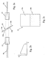
- Fig. 7 is a detailed side view of a transmissive filter in accordance with the invention;
- Fig. 8 is a detailed side view of a reflective filter in accordance with the invention;
- Fig. 9a is a detailed view of an etalon filter in accordance with an aspect of this invention
wherein one of the etalon reflective end faces has a continually varying reflectivity
(finesse) along a substantial portion of one of its end faces;
- Figs 9b is a graph of wavelength versus amplitude for the etalon filter shown in Fig. 9a,
wherein three plots are shown for the filter in three different positions with respect to an
input beam of light.
- Fig. 9c is a detailed view of an etalon filter in accordance with an aspect of this invention
wherein one of the etalon reflective end faces has a discretely varying reflectivity
(finesse) along a portion of one of its end faces;
- Fig. 9d is a detailed view of an etalon filter having variable reflectance surfaces at each
end;
-
Detailed Description
-
Referring now to Fig. 1 the gain spectrum of a typical EDFA amplifier is shown wherein
it can be seen that the gain as a function of wavelength varies.
-
For a wide variety of glass hosts, rare earth doped optical amplifiers and particularly
EDFAs are effectively homogeneously broadened, and the overlap of dopant ions with
the signal modes is nearly wavelength independent. As such, the gain spectrum, here
being the small signal gain that would be measured by a weak probe signal while the
operating point of the amplifier is fixed, is constrained to a single parameter family of
wavelength dependencies. Therefore if gain of the amplifier at some reference
wavelength is changed due to a change in input (i.e. , pump and/or signal power) the
amplifier gain at other wavelengths will change by well defined amounts that likely are to
be different from the amount of gain change at the reference wavelength. The wavelength
dependence of the amplifier gain change as of result of an input change is referred to
herein as dynamic gain tilt. Hence, the dynamic gain tilt is a distortion of the amplifier
gain spectrum for operating conditions that differ from the operating point for which the
amplifier was designed.
-
As it was pointed out in the background of this invention, filters have been provided
heretofore for offsetting and flattening the gain spectrum of conventional EDFAs.
However providing such a fixed filter does not provide a solution to controlling distortion
due to dynamic gain tilt a condition that varies with input power of the input optical
signal.
-
Turning now to Fig. 2a, an arrangement is shown in accordance with this invention,
wherein a filter 10, shown in detail in Fig. 2c has a first region 10a consisting of
substantially light transmissive material such as clear glass and a second region 10b
juxtaposed to the first region having a dichroic multi-layer interference filter disposed
thereon. The second region 10b in a preferred embodiment has a sloped transmission
response versus wavelength shown in Fig. 2b. The dimension of the first and second
region should be at least the size of the beam incident upon the filter. The term filter
used within this specification should include any medium provides an output signal
which alters a characteristic of light incident thereupon. In this embodiment, the filter is
disposed between two graded index (GRIN) lenses 12 in a conventional manner, wherein
the lenses are used to collimate light exiting the optical fibre 8a, to provide a collimated
beam at the input side of the filter 10, and for focusing the collimated beam that has
traversed the filter 10, for coupling the beam into the optical fibre 8b. Means for moving
the filter 10 along a line coincident with arrows 14a and 14b are provided ( not shown in
Fig. 2a); such means can conveniently be provided in the form of a stepper motor or
alternatively in the form of a piezo-electric actuator. Control circuitry and means for
moving the filter in dependence upon the control signal are well known in the art and
shall not be described.
-
In operation, the system in accordance with this invention functions in the following
manner. When the filter 10 is disposed in a position such that the beam incident thereon
passes entirely through the clear portion 10a of the filter 10, the amplitude of the beam as
a function of wavelength is essentially unchanged. Hence if the input beam has a
signature or amplitude response such as the spectrum shown in Fig. 1, the output beam
that has propagated through the clear portion of the filter 10a will essentially be
unaffected and will have the same amplitude response as a function of wavelength. On
the other hand, if an input beam has a positive gain tilt due to a change in power of the
input beam, passing this beam through the negatively sloped portion 10b of the filter 10
lessens the effect of the positive gain tilt. Most importantly and paramount to this
invention, the filter 10 is positionable and dynamically controlled by an actuator and
control circuitry (not shown) such that the filter is positionable at locations along the line
defined by the arrows 14a and 14b. Hence, a beam incident upon the filter 10 passes
through more or less of the portion 10b and less or more of the portion 10a, respectively
depending upon the position of the actuator. When a steeper sloped response is required
the filter 10 is moved into a position such that less of the beam passes through the clear
portion 10a of the filter 10 and more of the beam passes through the portion 10b. By
relatively varying position of the beam and the filter such that a greater portion of the
beam passes through the region 10b than the region 10a, the slope of the amplitude
response with wavelength is augmented, thus affording a means of dynamically
controlling for gain tilt. Conversely control of tilt in an opposite direction can be realized
by lessening the portion of the beam that passes through the region 10b and increasing
the portion that passes through the clear portion 10a of the filter 10. This is illustrated
more clearly by viewing Figs. 3a to 3d. Fig 3a illustrates a response of the filter 10 and
more particularly 10b as it would filter a beam of light 30 having a diameter of
approximately 300 µm, traversing the filter through the portion 10b, (as is shown in Fig.
3b). Fig. 3c illustrates a response of the same filter, for a same beam 30 traversing the
filter (as is shown in Fig. 3d) through both regions 10a and 10b. It is noted that the
absolute value of the slope of the line 32a is greater than the absolute value of the slope
of the line 32b since some of the light in Fig. 3d is passing through the clear portion of
the filter. In the extreme case, where all of the light is passing through the clear portion
10a of the filter, the filters response is flat, and as more of the light passes through the
portion 10b, the absolute value of the slope increases to a maximum, in dependence upon
the filter's characteristics.
-
Turning now to Fig. 4a, an alternative embodiment of the invention is shown,
wherein a first reflective filter 40 is shown having a first portion that is completely
reflective to all wavelengths, and a second portion having a reflection response with
wavelength shown in Fig. 4b. This embodiment works in a similar manner to the
embodiment shown in Fig. 2a, however it is based on reflection rather than transmission.
In both of the embodiments shown in Figs. 2a and 4a a filter having a second portion with
negative tilt is shown, however, alternatively a filter with portion with positive tilt can be
provided in instances where this is required.
-
Fig. 5a illustrates an arrangement similar to that of Fig. 2a, however the filter has
a first portion 10c having a response with a positive slope, and a second portion having a
response having a negative slope. Alternatively, a hybrid filter can be provided wherein a
clear portion 10a is provided having at its extremities filters 10b and 10c as have been
described.
-
Figs 5b and 5c show the output amplitude versus wavelength transmission
responses for the filters 10b and 10c respectively.
-
In another embodiment of this invention, a series of cascaded filters of this type
can be used as tunable gain flattening filters. Fig. 6a shows an embodiment according to
the invention wherein three filters 62, 64, and 66 are each tunable and designed to filter a
different wavelength band. Fig. 6b illustrates the response for the three filters, and a
dashed line in the graph illustrates the response of the individual filters. Less attenuation
can be provided for any of the three wavelength bands by positioning any of the filters
such that the beam traverses some or all of the no-attenuating portion of the filters.
-
In order to lessen unwanted effects of a difference in phase for part of the beam
traversing the thin film dichroic filter compared with that portion of the beam traversing
the clear glass substrate, the optical length of the two sections 10a and 10b can be
matched to the appropriate tolerance. Turning now to Fig. 7, a side view of a
transmissive filter in accordance with this invention is shown. Two glass blocks 70a and
70b are provided having an unattenuating substrate 72a and a thin film coated substrate
72b. The inner meeting edges of the two substrates 72a and 72b are polished. Between
the glass blocks and the substrates 72a and 72b is a refractive index matching epoxy 75.
-
Fig. 8 shows a detailed side view of a reflective split filter wherein only a single glass
block is required. An index matching epoxy is disposed between the glass block 70a and
a reflective thin film coated substrate 82b. Adjacent the substrate 82b is a glass substrate
82a having a reflective coating.
-
Turning now to Fig. 9a, an etalon filter 94 is shown having an input end face 96 coated in
such a manner as to have the reflectivity varying substantially linearly along its length in
a direction from high reflectivity to lower reflectivity towards the bottom of the filter.
The difference between the highest reflectivity and the lower reflectivity is greater than
10%. For example at the high end, the reflectivity might be 55% corresponding to a
finesse of approximately 5, and at the lower reflectivity end, where the desired slope may
be zero, the corresponding finesse or reflectivity would be zero. The opposite end face
97, in this example has a constant reflectivity coating along its length, however is not
limited to such. The etalon can conveniently made of a single light transmissive block
having two at least partially reflective end faces coated end faces. Since the input end
face has a coating with a reflectivity which varies along the length thereof, by moving the
light beam to be filtered and/or the lens, relatively, light will pass through the etalon such
that the etalon will have a different finesse at different relative positions. By so doing, the
slope of the output response of the etalon changes within a wavelength range of interest.
Of course the free spectral range of the etalon must be chosen to provide a suitable
window between two different adjacent zero sloping regions of the etalon, and of course
the etalon must be tuned or selected to such that the sign (+/-) of the slope is suitable to
offset the unwanted tilt of the amplifier to which it is coupled. Hence, a suitable fixed
etalon or tunable etalon can be used. In a preferred embodiment, the free spectral range
would likely exceed 10 nm, however in other applications it would be preferred to have
an etalon with an free spectral range which exceeds 0.5 nm.
-
Fig. 9b illustrates three output responses of the filter shown in Fig. 9a for light launched
into three locations along the varying reflective end face. A first sinusoidal-like wave
labeled 90a illustrates the amplitude output response versus wavelength for light
launched into location A. The second sinusoidal-like wave labeled 90b illustrates the
amplitude output response versus wavelength for light launched into location B; and the
third sinusoidal-like wave labeled 90c illustrates the amplitude output response versus
wavelength for light launched into location C. Since the amplitude of the three
sinusoidal-like waves is significantly different, the corresponding slopes of each of the
sinusoidal-like waveforms varies as well. By using this sloped part of the response as the
useful working range of the filter, and varying the slope within this working range
without varying the centre operating wavelength, a useful filter is provided for
controlling unwanted gain tilt from an in-line amplifier.
-
Fig. 9c is similar to that of Fig. 9a, however the input end face of the etalon has three
different discrete portions essentially providing a three-stepped-finesse etalon.
-
Fig. 9d shows an etalon wherein each end face has a variable reflectance; here a beam of
light incident at a location of the etalon would reflect between two surfaces having a
same reflectance, however when the input port is moved by relatively moving at least one
of the port and the etalon, the reflectance is varied.
-
Within this specification different regions of the filter may be distinct and different
regions, or alternatively may be different regions having some common portions. For
example relatively moving an input port and a variable reflectance face of the etalon
described heretofore, is considered launching a beam into different regions of the etalon
filter.
-
Of course, numerous other embodiments may be envisaged, without departing from the
sprit and scope of the invention. For example, in the embodiments shown heretofore, the
filter is shown and described to be movable, however, an embodiment wherein the beam
is shifted can be realized.