EP1063921B1 - Optical biopsy forceps system - Google Patents
Optical biopsy forceps system Download PDFInfo
- Publication number
- EP1063921B1 EP1063921B1 EP99909933A EP99909933A EP1063921B1 EP 1063921 B1 EP1063921 B1 EP 1063921B1 EP 99909933 A EP99909933 A EP 99909933A EP 99909933 A EP99909933 A EP 99909933A EP 1063921 B1 EP1063921 B1 EP 1063921B1
- Authority
- EP
- European Patent Office
- Prior art keywords
- tubular member
- biopsy forceps
- cutting jaws
- biopsy
- inner tubular
- Prior art date
- Legal status (The legal status is an assumption and is not a legal conclusion. Google has not performed a legal analysis and makes no representation as to the accuracy of the status listed.)
- Expired - Lifetime
Links
Images


Classifications
-
- A—HUMAN NECESSITIES
- A61—MEDICAL OR VETERINARY SCIENCE; HYGIENE
- A61B—DIAGNOSIS; SURGERY; IDENTIFICATION
- A61B10/00—Other methods or instruments for diagnosis, e.g. instruments for taking a cell sample, for biopsy, for vaccination diagnosis; Sex determination; Ovulation-period determination; Throat striking implements
- A61B10/02—Instruments for taking cell samples or for biopsy
- A61B10/06—Biopsy forceps, e.g. with cup-shaped jaws
-
- A—HUMAN NECESSITIES
- A61—MEDICAL OR VETERINARY SCIENCE; HYGIENE
- A61B—DIAGNOSIS; SURGERY; IDENTIFICATION
- A61B18/00—Surgical instruments, devices or methods for transferring non-mechanical forms of energy to or from the body
- A61B18/04—Surgical instruments, devices or methods for transferring non-mechanical forms of energy to or from the body by heating
- A61B18/12—Surgical instruments, devices or methods for transferring non-mechanical forms of energy to or from the body by heating by passing a current through the tissue to be heated, e.g. high-frequency current
- A61B18/14—Probes or electrodes therefor
- A61B18/1442—Probes having pivoting end effectors, e.g. forceps
-
- A—HUMAN NECESSITIES
- A61—MEDICAL OR VETERINARY SCIENCE; HYGIENE
- A61B—DIAGNOSIS; SURGERY; IDENTIFICATION
- A61B10/00—Other methods or instruments for diagnosis, e.g. instruments for taking a cell sample, for biopsy, for vaccination diagnosis; Sex determination; Ovulation-period determination; Throat striking implements
- A61B10/02—Instruments for taking cell samples or for biopsy
- A61B2010/0216—Sampling brushes
-
- A—HUMAN NECESSITIES
- A61—MEDICAL OR VETERINARY SCIENCE; HYGIENE
- A61B—DIAGNOSIS; SURGERY; IDENTIFICATION
- A61B17/00—Surgical instruments, devices or methods, e.g. tourniquets
- A61B2017/00017—Electrical control of surgical instruments
- A61B2017/00022—Sensing or detecting at the treatment site
- A61B2017/00057—Light
- A61B2017/00061—Light spectrum
-
- A—HUMAN NECESSITIES
- A61—MEDICAL OR VETERINARY SCIENCE; HYGIENE
- A61B—DIAGNOSIS; SURGERY; IDENTIFICATION
- A61B17/00—Surgical instruments, devices or methods, e.g. tourniquets
- A61B17/22—Implements for squeezing-off ulcers or the like on the inside of inner organs of the body; Implements for scraping-out cavities of body organs, e.g. bones; Calculus removers; Calculus smashing apparatus; Apparatus for removing obstructions in blood vessels, not otherwise provided for
- A61B2017/22072—Implements for squeezing-off ulcers or the like on the inside of inner organs of the body; Implements for scraping-out cavities of body organs, e.g. bones; Calculus removers; Calculus smashing apparatus; Apparatus for removing obstructions in blood vessels, not otherwise provided for with an instrument channel, e.g. for replacing one instrument by the other
-
- A—HUMAN NECESSITIES
- A61—MEDICAL OR VETERINARY SCIENCE; HYGIENE
- A61B—DIAGNOSIS; SURGERY; IDENTIFICATION
- A61B17/00—Surgical instruments, devices or methods, e.g. tourniquets
- A61B17/28—Surgical forceps
- A61B17/29—Forceps for use in minimally invasive surgery
- A61B2017/2901—Details of shaft
- A61B2017/2905—Details of shaft flexible
-
- A—HUMAN NECESSITIES
- A61—MEDICAL OR VETERINARY SCIENCE; HYGIENE
- A61B—DIAGNOSIS; SURGERY; IDENTIFICATION
- A61B90/00—Instruments, implements or accessories specially adapted for surgery or diagnosis and not covered by any of the groups A61B1/00 - A61B50/00, e.g. for luxation treatment or for protecting wound edges
- A61B90/36—Image-producing devices or illumination devices not otherwise provided for
- A61B90/361—Image-producing devices, e.g. surgical cameras
- A61B2090/3614—Image-producing devices, e.g. surgical cameras using optical fibre
Definitions
- the present invention relates generally to medical diagnosis and treatment. More particularly, it pertains to a reusable and disposable biopsy forceps device having an optical fiber for optical biopsy and histopathological analysis of tissue.
- biopsy forceps Numerous types have been developed for in vivo medical diagnosis and treatment of various conditions. Such devices are designed for sampling tissue within the body, for example in endoscopic, laparoscopic and vascular procedures to retrieve biopsy samples for analysis and identification of tissue types. These biopsy forceps devices generally include small cutting jaws at the distal end, operated remotely from the proximal end after the distal end of the device has been positioned or navigated to the site of interest.
- This patent discloses a biopsy forceps with a flexible outer tube, cutting jaws, an inner tubular member extending through the outer tube, an actuator mechanism and an access port.
- One type of prior art system for internal biopsy uses an optical catheter to locate the site, followed by replacement of the optical catheter with a biopsy forceps for taking a tissue sample.
- this can result in errors and uncertainties in the final placement of the biopsy jaws with respect to a previously identified small structure or targeted area since the exact site identified by the optical catheter is not treated with the biopsy forceps or other instruments to treat the site.
- Another difficulty in conventional devices is accessing the area from which the biopsy sample is to be taken. Often the area to be sampled requires treatment before the sample is taken.
- An optical catheter is used to locate the biopsy site, followed by replacement of the optical catheter with a medical instrument for treating the area. The instrument is removed, and biopsy forceps is inserted for taking a biopsy sample.
- this can result in errors and uncertainties in the final placement of the biopsy jaws with respect to a previously identified small structure or biopsy area.
- biopsy devices allow for a biopsy sample to be pierced with a spike before the biopsy sample is taken.
- these devices are limited to the fixed instrument disposed within the forceps. If additional instruments and treatment is necessary for the biopsy area, the biopsy device must be removed from the body, and a different device inserted into the body. Removing the device to insert another poses additional problems in that the exact biopsy location will not be treated.
- an integrated biopsy forceps device which is very thin, with an access lumen enabling the device to be used in very small areas of interest, and which allows for accurate alignment with repetitive withdrawal or introductions of various adjunctive medical instruments to treat the biopsy sampling area.
- a system is also provided where an integrated biopsy forceps device is coupled with an electro-optical diagnostic apparatus for optical biopsy to perform histopathological analysis of tissue.
- the present invention in one embodiment, provides a biopsy forceps which is adapted for tissue treatment and identification through the access lumen and by biopsy sampling.
- the forceps device includes an elongated catheter body for introduction into the body and navigation to an area of interest.
- the distal end of the forceps device has a pair of cutting jaws, and a lumen extends through the forceps device aligning with the closed cutting position of the cutting jaws.
- the proximal end has a handle portion for manipulating the forceps device and actuating the jaws.
- the device of the invention may be used in a method of treating tissue at a site within a body.
- the method comprises introducing into the body a biopsy forceps which includes a flexible catheter body with an access lumen extending therethrough with the distal end of the lumen aligned with a biopsy sampling area adjacent the distal tip of the catheter body. Instruments such as an optical fiber, are inserted into the device and through the lumen to treat the sampling area as appropriate.
- the biopsy forceps additionally include cutting jaws mounted at the distal end of the catheter body for selective opening and closing in a biopsy cutting movement in the biopsy sampling area, and an actuator mechanism operatively connected to the jaws for selectively controlling the opening and closing of the cutting jaws.
- tissue in the biopsy sampling area adjacent the distal end of the forceps is treated with the instruments inserted through the forceps or identified by the optical fiber coupled with the electro-optical diagnostic apparatus.
- the area is flushed with medicine or saline with or without the optical fiber inserted in the lumen.
- a biopsy sample is cut from the location of the optical tissue analysis zone by actuating the actuator mechanism, and the biopsy sample is withdrawn from the body.
- the cutting jaws are mounted for pivoting about stationary pivot pins for cutting tissue placed there between, and coupled to and controlled by an inner tubular member forming the lumen that extends through the catheter body to the handle portion at the proximal end of the device.
- the inner tubular member extends through the handle and couples with an access portion on the handle portion. Instruments, medicine, or fluids are inserted into the access portion and through the lumen to treat, flush, or clean the biopsy sampling area.
- the inner tubular member is positioned coaxially with the jaws, so that the biopsy sample is taken exactly at the spot where treatment with instruments or fluids took place.
- a second lumen is provided adjacent the lumen within the inner tubular member to provide additional access proximate the biopsy sampling area.
- the cutting jaws are mounted for pivoting about stationary pivot pins for cutting tissue placed therebetween, and controlled by control wires extending through the catheter body to the control handle and/or an inner member.
- the cutting jaws are rotatably coupled with a distal housing and are controlled by links.
- the links in another embodiment, are operatively coupled with the actuator housing and the cutting jaws.
- the inner member has a lumen therein and extends through the device, from its proximal end for coupling with an access port.
- An optical fiber is disposed within the lumen of the inner member.
- the control wires are disposed in grooves formed in the inner member and the wires and the inner member are coupled with a handle for actuating the cutting jaws.
- the cutting jaws are mounted for pivoting about stationary pivot pins and are for cutting tissue placed between the cutting jaws, and coupled to and controlled by an inner tubular member that extends through the catheter body to the handle portion at the proximal end of the device.
- the inner tubular member has a plurality of lumens therein with an optical fiber disposed in at least one of the lumens, and extends through the handle and couples with an access portion on the handle portion. Instruments, medicine, or fluids are inserted into the access portion and through the lumen to treat the biopsy sampling area.
- the inner tubular member is positioned coaxially with the jaws, so that the biopsy sample is taken exactly at the spot where treatment with instruments or fluids took place.
- the biopsy forceps is reusable.
- the entire biopsy forceps does not need to be discarded. Instead, a new optical fiber is inserted through the central access lumen when the use of the previous optical fiber is exhausted. Removing the optical fiber from the biopsy forceps also allows for the forceps to be cleaned and sterilized more extensively using more thorough and strenuous processes.
- the biopsy forceps is disposable. Using disposable biopsy forceps helps to reduce the chance of contamination between patients where a biopsy forceps is disposed after use on one patient, which is ideal for patients with highly contagious and dangerous diseases or patients highly susceptible to infection.
- One important use of the invention is in connection with endoscopic treatment and diagnosis procedures, for example in gastrointestinal endoscopy or bronchoscopy.
- the present invention is also useful in many other endoscopic fields including, but not limited to: urology, cardiovascular, neurology, orthopedics, general surgery, laparoscopy, obstetrics/gynecology, etc. It can also be used in minimally invasive laparoscopic procedures for additional diagnostic information, and/or guidance of a therapeutic modality (e.g., laser or cutting/coagulation devices, such as a bipolar or monopolar electrocautery RF device).
- a therapeutic modality e.g., laser or cutting/coagulation devices, such as a bipolar or monopolar electrocautery RF device.
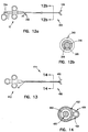
- Figure 1 illustrates a system including a biopsy forceps 10 and a diagnostic apparatus 1000, such as a spectrophotometer.
- the electro-optical diagnostic apparatus 1000 comprises a light source 1030, a spectral analyzer 1040, and a computer 1050.
- Forceps 10 includes an optical fiber 900 disposed therethrough, as is explained in greater detail below.
- the optical fiber 900 is coupled with the fiber coupler 1020 and the light source 1030 of the diagnostic apparatus 1000.
- the light source 1030 provides a source of optical radiation, where operation of the light source 1030 is, in one embodiment, controlled by the computer 1050. Operation of the light source 1030 transmits radiation into the fiber coupler 1020. The radiation emanates from the optical fiber 900 upon a tissue location (not shown). The radiation returning from the tissue by reflection or fluorescence is received by the optical fiber 900 and the fiber coupler 1020 which then transmits the returning radiation to the spectral analyzer 1040.
- the computer 1050 further analyzes the information from the spectral analyzer 1040 and outputs the information to a display (not shown). The system is not limited to the diagnostic technique described above.
- the system according to the present invention is designed for use in methods utilizing any optically based diagnostic techniques, including laser induced fluorescence, time-resolved fluorescence, Raman spectroscopy, optical coherence tomography, etc.
- optically based diagnostic techniques including laser induced fluorescence, time-resolved fluorescence, Raman spectroscopy, optical coherence tomography, etc.
- Alternative techniques of diagnosing tissue from the data received from the optical fiber will be known to those skilled in the art and will not be described further herein.
- the biopsy forceps 10 is shown in greater detail in Figure 2.
- the biopsy forceps 10 is adapted for use internally of the body, for example in connection with endoscopic, laparoscopic or vascular procedures.
- Forceps 10 includes a control handle portion 12 at a proximal end 15, a middle portion 14 which extends over the main length of the device, and a distal end 16 which includes opposed forceps cutting jaws 120, as is explained in greater detail below.
- the main body or length of the forceps 10 consists of coaxial inner and outer tubular members 20, 22, as shown in more detail in Figure 3.
- the outer tubular member 22 is small enough such that it can be inserted within a working channel of an endoscope.
- the inner tubular member 20 is a stainless steel tube
- the outer tubular member 22 or catheter body is a coil.
- the inner tubular member 20 comprises a coiled stainless steel tube.
- the coil is a finely wound spiral coil of stainless steel as is generally known and used in catheters and guidewires.
- the outer tubular member 22 or the inner tubular member 20 could be made using a plastic tube, or a plastic/metal composite structure, in place of the coil.
- the inner tubular member 20 is positioned within the outer tubular member 22 and these components are dimensioned with respect to each other so that inner tubular member 20 moves freely within the outer tubular member 22 to actuate the jaws, as is explained in more detail below.
- the inner tubular member 20 has a central access lumen 28 extending through the inner tubular member 20 from the proximal end 15 to the distal end 16.
- the access lumen 28 is sized to receive the optical fiber 900 therethrough.
- the optical fiber 900 in one embodiment, is removably disposed within the access lumen 28.
- the access lumen 28 is sized larger than the optical fiber 900, in one embodiment, such that a fluid (e.g.
- the inner tubular member 20 is coupled with an actuator housing 60.
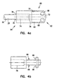
- the actuator housing 60 shown in more detail in Figures 4a and 4b is, in one embodiment, fabricated from stainless steel material. Alternatively, the actuator housing 60 can be formed from other substantially rigid materials.
- the actuator housing 60 extends from a first end 62 to a second end 64, and generally comprises an elongate cylinder.
- the actuator housing 60 has flats 66 formed proximate the first end 62. Disposed on the flats 66 are cam pins 68 having a generally circular cross-section, as shown.
- the cam pins 68 are integral with the flats 66 of the actuator housing 60.
- the actuator housing 60 can be machined or molded from a single piece of material.
- the cam pins 68 can be integrally formed with the flats 66 by attaching the projections to the flats 66 using, for example, adhesive or welding processes.
- the cam pins 68 are for coupling with the jaws, as will be further explained below.
- the actuator housing 60 has a bore 70 extending from the first end 62 to the second end 64, where the bore has a first portion 72 and a second portion 74.
- the first and second portions 72, 74 form a shoulder 76 in between.
- the first portion 72 has a smaller diameter than the inner tubular member 20, yet large enough to allow the optical fiber 900 to pass through the first portion 72.
- the first portion 72 is large enough to allow other medical devices to pass through, such as the devices shown in Figures 16a - 16g.
- the inner tubular member 20 is inserted within the second portion 74 of the actuator housing 60 until, in one embodiment, inner tubular member 20 contacts the shoulder 76 of the actuator housing 60. In another configuration, the inner tubular member 20 can be placed proximate to shoulder 76.
- the access lumen 28 of the inner tubular member 20 is substantially aligned with the bore 70 of the actuator housing 60, thereby facilitating insertion of the optical fiber 900 or the medical devices through the access lumen 28 and through the bore 70.
- the inner tubular member 20 is coupled with the actuator housing 60, where in one embodiment, the inner tubular member 20 is secured to the actuator housing 60 with a weld 78.
- the inner tubular member 20 can be joined with the actuator housing 60 by solder, brazing, or adhesive techniques as is known by those skilled in the art.
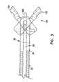
- FIGS 3, 5a and 5b show the cutting jaws 120 in more detail.
- the cutting jaws 120 are comprised of a first jaw 122 and a second jaw 124 which, in one embodiment, are mirror images of each other. Since the first jaw 122 and the second jaw 124 are similar, only the first jaw 122 will be discussed.
- the jaw 122 has an actuation portion 132 and a cutting portion 136. Within the cutting portion 136, the jaw 122 has a hemispherical cup 126 with sharpened edges 130 for taking biopsy samples.
- the cup 126 of jaw 122 has, in one embodiment, a hole 128 disposed therein. The hole 128 advantageously facilitates cutting the biopsy sample at the site within the body, and also facilitates the removal of the biopsy specimens captured by each cup 126.
- the jaw 122 has a cut out 138 for forming a pivot point for the jaw 122.
- the cut out 138 is generally circular in shape and sized to receive a projection of a distal housing, as will be further discussed below.
- the actuation portion 132 also includes a cam slot 140, which in one embodiment is arcuately shaped.
- the cam slot 140 couples with the cam pin 68 of the actuator housing 60.
- the cam slot 140 is sized to receive the cam pin 68 therein, and allows for radial movement of the jaw 122 about the pivot point as the cam pin 68 of the actuator housing 60 is moved along the axis of the biopsy forceps 10.
- the movement of the jaw 122 about the pivot point allows for radial movement of the cutting jaws 120, without axial movement of the cutting jaws 120. This provides a further benefit since the jaws more accurately cut the biopsy sample at the exact position identified using the optical fiber 900.
- Biopsy forceps 10 also includes a distal housing 90, as shown in more detail in Figure 6.
- the distal housing 90 is a generally elongate cylinder having a radial axis 106 and extending from a first end 92 to a second end 94.
- the housing 90 is fabricated from, in one embodiment, stainless steel material.
- Disposed proximate the first end 92 are flats 96.
- the flats 96 each form a surface which is parallel to each other.
- the flats 96 each have a pivot pin 100 disposed thereon.
- the pivot pin 100 couples with the cut out 138 in each of the cutting jaws 120, and allows the cutting jaws 120 to rotate about the pivot pin 100.
- the flats 96 have a cut out 98 extending through the housing 90.
- the cut out 98 is generally square shaped and is disposed perpendicular to the radial axis 106 of the housing 90, as shown in Figure 6.
- the cut out 98 is sized to allow the actuator housing 60 to travel along the radial axis 106 of the housing 90 sufficient to actuate the cutting jaws 120 without interference from the distal housing 90.
- the bore 102 is aligned with the radial axis 106 of the housing 90 and extends from the first end 92 to the second end 94.
- the bore 102 has its largest diameter proximate the second end 94, and tapers to a second bore portion 108.
- the housing 90 has a third bore portion 110 proximate the first end 92 of the housing 90.
- the bore 102 is sized to receive the outer tubular member 22 therein.
- the outer tubular member 22 is secured to the housing 90 by welding, brazing, soldering, adhesives, or other equivalents known to those skilled in the art.
- the second bore portion 108 is sized to receive the actuator housing 60 therethrough, and to allow the actuator housing 60 to travel axially to actuate the jaws 120.
- the third bore portion 110 is sized to freely receive the optical fiber 900 or medical devices such as those shown in Figures 16a - 16g, such that the fiber 900 or the devices can be used through the cutting jaws 120.
- the biopsy forceps 10 includes the handle portion 12 for facilitating actuation of the inner tubular member 20.
- the handle portion 12 includes a handle 42 and a translation member 46, and loops 24, 25, 26. Loops 24, 25, 26 are provided in the handle portion 12 to form finger holes useful in grasping and manipulating the forceps 10.
- the handle 42 is fastened to the translation member with a fastener 44.
- the inner tubular member 20 is fastened to the translation member by welding, brazing, soldering, adhesives, or other mechanical fasteners such that movement of the handle 42 results in movement of the inner tubular member 20.
- a luer fitting 48 is threaded into the translation member 46.
- the translation member 46 has a bore (not shown) therethrough, which provides a conduit between the luer fitting 48 and the inner tubular member 20.
- the luer fitting 48 in combination with the bore of the translation member 46 provide access to the lumen 28 and allows for ease of cleaning and reusability of the biopsy forceps 10.
- the handle portion 12 can include any type of actuating mechanism capable of imparting bidirectional axial movement to the inner tubular member 20 of biopsy forceps 10.
- the handle 42 in operation, is retracted toward the back of handle portion 12 to close the jaws. Retraction of the handle 42 causes movement of the inner tubular member 20 and the actuator housing 60 toward the handle portion 12, and closes the cutting jaws 120.
- the distal end 16 of the forceps 10 is of the same narrow diameter as the main body of a forceps catheter, and the closed jaws have a smooth, rounded shape to facilitate introduction and navigation in the vascular, endoscopic or laparoscopic systems.
- the cutting jaws are coaxially positioned with respect to the distal end of the inner tubular member 20.
- the endoscopist advances the biopsy forceps 10 through a working channel of the endoscope to the general area of interest, i.e., such as a tissue site.
- the forceps jaws can be opened by advancing the handle 42 toward the distal end 16 of the forceps 10, thereby advancing the translating member 46 away from the handle 42.
- This causes the inner tubular member 20 to move away from the handle 42, which in turn causes the actuator housing 60 to be axially moved towards the distal end 16 of the forceps.
- the cam pins 68 on the actuator housing 60 move within the cam slots 140 of the cutting jaws 120, causing the cutting jaws 120 to open.
- the area can now be treated through the lumen using various medical instruments, flushed with saline, or treated with medicine. If other medical instruments are necessary, the optical fiber 900 is removed from the lumen 28, and a new instrument is inserted therein. If a biopsy of the area is necessary, the handle 42 is retracted toward the proximal end 15 of the forceps 10, retracting the inner tubular member 20, and causing the cutting jaws 120 to close and cut a biopsy sample at the exact place that had been treated and/or identified.
- the endoscopist holding the instrument by the handle portion 12 gently pulls back on the handle 42, retracting the inner tubular member 20, and closing the cutting jaws 120 on the biopsy sample.
- the jaws 120 When the jaws 120 are closed, the endoscopist pulls the entire assembly away from the tissue surface and out of the body.
- an instrument is inserted into the hole 128 in the hemispherical cup 126 of one of the cutting jaws 120 or the cutting jaws 120 can be flushed with saline to remove the sample.
- FIG. 7 another embodiment of a biopsy forceps of the present invention is generally indicated by reference number 200.
- the biopsy forceps 200 is generally similar to the biopsy forceps 10 shown in Figure 1, and accordingly, corresponding elements have been given the same reference number.
- the biopsy forceps is adapted for use internally of the body, for example in connection with endoscopic, laparoscopic or vascular procedures.
- the forceps 200 includes a handle portion 12 at the proximal end 15, a middle portion 14 which extends over the main length of the device, and a distal end 16.
- the distal end 16 includes forceps cutting jaws 120.
- the forceps 200 has a coaxial inner member 220 and an outer tubular member 222, as shown in Figure 8.
- the outer tubular member 222 and the inner member 220 each extend generally from the proximal end 15 to the distal end 16 of the forceps 200.
- the outer tubular member 222 in one embodiment, comprises a finely wound spiral coil of stainless steel as is generally known and used in catheters and guidewires.
- the outer tubular member 222 could be made using a plastic tube, or a plastic/metal composite structure, in place of the stainless steel spiral coil.
- the outer tubular member 222 has a lumen therethrough which is sized to received the inner member 220 therein.
- the inner member 220 comprises a polymer tube which is extruded with a lumen 230 therein.
- the inner member 220 comprises a plastic tube or a combination of metal and plastic.
- the lumen 230 is sized to receive an optical fiber 250 therein. Secured to at least a portion of the optical fiber 250, the inner member 220 forms a cladding for the optical fiber 250.
- grooves 232, 234 are formed in the perimeter of the inner member 220.
- the grooves 232, 234 form a cavity within the inner member 220 and can also take the form of an indentation or a lumen.
- the grooves 232, 234 are disposed on opposite sides of the lumen 230.
- control wires 240, 241 Positioned within the grooves 232, 234 of the inner member 220 are a pair of control wires 240, 241, which in one embodiment comprise stainless steel cables. These components, together with outer tubular member 222 and inner member 220 extend over the main length of the device, from the distal end 16 to the handle portion 12 ( Figure 7).
- the handle portion 12 includes a translating member 244, which in one embodiment, comprises an aluminum block.
- the handle 242 is fastened to the translation member 244 with fastener 44.
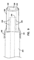
- Both the inner member 220 and the control wires 240, 241 are secured to the translating member 244, shown in more detail in Figure 9.
- the translating member 46 has a projection 246 for securing the inner member 220 with the handle 242.
- the projection 246, comprising a generally elongate cylinder, has ridges 248, 249 disposed around the perimeter of the projection 246.
- the ridges 248, 249 of the projection 246 engage the lumen 230 of the inner member 220 and prevent the inner member 220 from disengaging from the handle 242.
- the control wires 240, 241 are secured to the translating member 244 by either welding, soldering, brazing, adhesives, a mechanical fastener, or other alternatives as known by those skilled in the art.
- the inner member 220 and the control wires 240, 241 are secured to translating member 244 which together, in one embodiment, form an actuator mechanism for the forceps 200. Movement of translating member 244 causes axial movement of the inner member 220 and the control wires 240, 241 relative to outer tubular member 222, which is used to actuate the cutting jaws 120. Loops 226, 227, and 228 are provided in handle portion 12 to form finger holes useful in grasping and manipulating the forceps 200 ( Figure 7).
- the inner member 220 extends from the handle portion 12 to the distal end 16. Coupled to the inner member 220 and the control wires 240, 241 at the distal end 16 is an actuator housing 260.
- the actuator housing 260 shown in more detail in Figure 10 is, in one embodiment, fabricated from stainless steel material, and generally comprises an elongate cylinder.
- the actuator housing 260 extends from a first end 262 to a second end 264, and has flats 266 formed proximate the first end 262.
- cam pins 268 Disposed on the flats 266 are cam pins 268 having a generally circular cross-section, as shown. In one embodiment, the cam pins 268 are integral with the flats 266 of the actuator housing 260.
- the actuator housing 260 can be machined or molded from a single piece of material.
- the cam pins 268 can be integrally formed with the flats 266 by attaching the cam pins 268 to the flats 266 using, for example, adhesive or welding processes.
- the cam pins 268 are for coupling with the jaws 120, as will be further explained below.
- the actuator housing 260 has a bore 270 which extends through the actuator housing 260 from the first end 262 to the second end 264 and is sized to receive the optical fiber 250 therethrough.
- the bore 270 of the actuator housing 260 aligns with the lumen 230 of the inner member 220 so that access to the distal end 16 is not prevented.
- the bore 270 allows for the optical fiber 250 to be inserted through the inner tubular member 220 and through the actuator housing 260 to the cutting jaws 120.
- the actuator housing 260 has attachment features so that the inner member 220 can be coupled with the actuator housing 260.
- the actuator housing 260 has ridges 272 disposed about the perimeter of the actuator housing 260, proximate to the second end 264. The ridges 272 engage the surface of the lumen 230 to retain the inner member 220 on the actuator housing 260.
- the actuator housing 260 can be coupled with the inner member 220 in other manners, for example, adhesives.
- the control wires 240, 241 are also secured to the actuator housing 260.
- the control wires 240, 241 are secured to the actuator housing at reference number 255 by either welding, soldering, brazing, adhesives, or a mechanical fastener. During use, both the actuator housing 260 and the control wires 240, 241 provide the axial force to the actuation portion 132 of the cutting jaws 120.
- the biopsy forceps 200 has a distal housing having the same structure as discussed above, and as shown in Figure 6.
- the outer tubular member 222 of the biopsy forceps 200 is secured to the housing, as in the previous embodiment, and therefore will not be further discussed.
- the biopsy forceps 200 also includes cutting jaws 120.
- the cutting jaws 120 are also the same as in the previous embodiment, and one of the cutting jaws 120 is as shown in Figures 5a and 5b.
- the jaw 122 has a cut out 138 and a cam slot 140.
- the cut out 138 forms a stationary pivot point for the jaw 122, and receives the pivot pins 100 of the housing 90 therein.
- the cam slot 140 couples with the cam pins 268 of the actuator housing 260, and allows for radial movement of the jaw 122 about the pivot point as the cam pins 268 of the actuator housing 260 are moved along the axis of the biopsy forceps 200.
- a further benefit is obtained since the cutting jaws 120 do not move axially during the cutting process. Instead, the cutting jaws 120 rotate about the stationary pivot point. This allows for more precise cutting of the biopsy site identified by the optical fiber.
- the handle 242 is retracted toward the back of handle portion 12 to close the jaws.
- This causes movement of the inner member 20, the control wires 240, 241, and the actuator housing 260 toward the handle portion 12, and closes the cutting jaws 120.
- the distal end 16 of the forceps 10 is of the same narrow diameter as the main body of a forceps catheter, and the closed jaws have a smooth, rounded shape to facilitate introduction and navigation in the vascular, endoscopic or laparoscopic systems.
- the cutting jaws are coaxially positioned with respect to the distal end of the inner tubular member.
- the cutting jaws 120 can be opened by pushing handle 42 of the control handle forward, away from the handle portion 12. This causes movement of the translation member 244, the inner member 220, the control wires 240, 241, and the actuator housing 260 away from the handle portion 12.
- the control wires 240, 241 and the inner member 220 push against the actuator housing 260.
- the cam pins 268 on the actuator housing 260 move within the cam slots 140 of the cutting jaws 120, and cause the jaws 120 to open.
- the distal end 16 of the forceps 10 is positioned at the area of contact.
- the optical fiber 250 when connected to the electro-optic diagnostic apparatus, can then be used for optical biopsy to perform histopathological analysis of the tissue site.
- the handle 242 is pulled toward the proximal end 15 of the forceps 10, causing the jaws 120 to close and cut a biopsy sample.
- the biopsy sample is cut from the exact tissue site identified as the biopsy site without requiring moving or repositioning of the catheter body.
- the forceps may then be withdrawn from the patient to recover the sample for analysis.
- the analysis of the withdrawn sample can be conducted using known laboratory techniques to confirm the identification of the tissue sample.
- FIG 11 illustrates another embodiment of an optical biopsy forceps 280.
- the optical biopsy forceps 280 includes cutting jaws 304, a coaxial inner member 276 and an outer tubular member 278 which each extend proximate the distal end of the forceps 280.
- the inner member 276 is extruded with a lumen 282 therein.
- the inner member 276 comprises a plastic tube or a combination of metal and plastic.
- the lumen 282 is sized to receive an optical fiber 900 therein.
- the inner tubular member 276 is positioned within the outer tubular member 278 and these components are dimensioned with respect to each other so that inner tubular member 276 moves freely within the outer tubular member 278 to actuate the jaws 304.
- the optical fiber 900 in one embodiment, is removably disposed within the lumen 282.
- the inner tubular member 276 is coupled with an actuator housing 290 such that movement of the inner tubular member 276 causes movement of the actuator housing 290.
- the actuator housing 290 is, in one embodiment, fabricated from stainless steel material. Alternatively, the actuator housing 290 can be formed from other substantially rigid materials.
- the actuator housing 290 includes at least one pin 292.
- the pins 292 are adapted to couple with a link coupling 297 of a first and second link 296, 298.
- the actuator housing 290 has a bore 294 therethrough, which allows passage of the optical fiber 900 therethrough.
- the bore 294 of the actuator housing 290 is aligned with the lumen 282 of the inner tubular member 276, thereby facilitating insertion of the optical fiber 900, or other medical device through the access lumen 282 and through the bore 294.
- the inner tubular member 276 is coupled with the actuator housing 290, where in one embodiment, the inner tubular member 276 is secured to the actuator housing 290 with a weld. Alternatively, the inner tubular member 276 can be joined with the actuator housing 290 by solder, brazing, or adhesive techniques.
- the cutting jaws 304 are comprised of a first jaw 306 and a second jaw 308.
- the cutting jaws 304 each have a cut out for forming a pivot point for each jaw 304.
- the cut out is generally circular in shape and sized to receive a projection of a distal housing 284, as will be further discussed below.
- the cutting jaws 304 each have a coupling 312 for attaching the jaws 304 with a link coupling 297 the first and second links 296, 298.
- the coupling 312 comprises a lug 314 disposed on the jaws 304, which couples with the link coupling 297 of the first and second links 296, 298.
- the forceps 280 also includes a distal housing 284.
- the distal housing 284 includes at least one pivot pin 286 disposed thereon. Each pivot pin 286 is adapted to couple with the cut out in each of the cutting jaws 304, and allows the cutting jaws 304 to rotate about the pivot pin 286.
- the distal housing 284 has a lumen 288 therein which allows passage of the optical fiber 900 therethrough.
- control wires (See Figures 7 - 9) could be coupled with the first and second links 296, 298.
- the control wires would apply an axial force to the first and second links 296, 298, and would be used to rotate the cutting jaws 304 about the pivot pins 286.
- the inner tubular member 276 would be directly coupled with the distal housing 284.
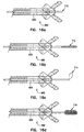
- the handle 42 ( Figures 1 and 2) is retracted to close the jaws 304. Retraction of the handle 42 causes axial movement of the inner tubular member 276 and the actuator housing 290 toward the handle 42, and closes the cutting jaws 304.
- the jaws 304 can be opened by advancing the handle 42 toward the distal end of the forceps 280. Advancing the handle 42 causes the inner tubular member 276 to move away from the handle 42, which in turn causes the actuator housing 290 to be axially moved towards the distal end of the forceps.
- the first and second links 296, 298 push upon the jaws 304 causing the first and second links 296, 298 to rotate around the couplings on both the actuator housing 290 and the jaws 304.
- the cutting jaws 304 rotate about the pivot pins 286 on the distal housing 284 and move to an open position.
- the inner member 220 and the control wires 240, 241 both actuate the radial movement of the cutting jaws 120.
- the combination of devices allows the operator to apply more axial force to the inner member 220 and the control wires 240, 241 thereby resulting in additional torque to the cutting jaws 120.
- the additional torque provides better cutting actuation, particularly in biopsy sites with tissue that is difficult to cut with the relatively small cutting jaws 120.
- the biopsy forceps is disposable, although the biopsy forceps can be reusable. Forming the inner member 220 from the polymer material helps to provide an inexpensive forceps 10 for disposal after use. In addition, using disposable biopsy forceps eliminates the chance of contamination between patients where a biopsy forceps is disposed after use on one patient, which is ideal for patients with highly contagious and dangerous diseases or patients highly susceptible to infection.
- FIGS 12a and 12b illustrate yet another embodiment of the present invention.
- a biopsy forceps 300 is provided having multiple access lumens.
- the general configuration of the biopsy forceps 300 is the same as the first discussed embodiment where an inner tubular member 320 is slidably received by an outer tubular member 340.
- the inner tubular member 320 actuates the cutting jaws 120, as discussed above.
- the inner tubular member 320 has a plurality of lumens disposed therein.
- an optical fiber is disposed therethrough.
- the plurality of lumens allow for other components or materials (such as fluids) to be inserted through the inner tubular member simultaneously with the optical fiber.
- a gap 316 between the inner surface of the outer tubular member and the outer surface of the inner tubular member 320 provides a secondary lumen 318.
- the secondary lumen 318 allows for fluids such as saline or medicine to be administered to the biopsy area. During use, the fluids travel through the secondary lumen 318 and are expelled through openings between the distal housing 90 and the cutting jaws 120 ( Figure 3) to treat the biopsy area.
- Access to the primary lumen is at a primary port 334.
- a secondary port 332 is provided proximate the handle portion 12.
- the secondary port in one embodiment, comprises a luer fitting as known by those skilled in the art.
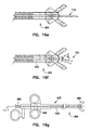
- FIGS 13 and 14 illustrate another embodiment of the present invention.
- a biopsy forceps 400 are provided with cutting jaws 480, a handle portion 412, and a main body 414 in between.
- the main body 414 has an inner tubular member 420, which actuates the cutting jaws 480 and is disposed within an outer tubular member 422, as discussed above.
- Disposed within the inner tubular member 420 is an optical fiber 450.
- a third tubular member 424 is coupled with the main body 420.
- the third tubular member 424 is secured to the outer surface of the outer tubular member 422 as shown in Figure 14 by welding, brazing, soldering, or adhesive.
- a polymer heat-shrink jacket 426 is placed over the outer tubular member 422 and the third tubular member 424 to thereby couple the third tubular member 424 with the outer tubular member 422.
- the outer jacket coating provides the forceps 400 with a smooth surface for ease of use within the patient.
- the above biopsy forceps 500 are provided with electro-cauterizing capability.
- a connector pin 510 is provided on the handle portion 12.
- the connector pin 510 forms an electrical connection which is compatible with standard electro/surgical equipment.
- a protective collar 522 surrounds the connector pin 510, preventing inadvertent contact with the connector pin 510.
- the collar 522 protects the connector pin 510 from being damaged.
- the inner tubular member 520 comprises a stainless steel tube, which is coupled with the connector pin 510.
- the inner tubular member 520 comprises a polymer tube with steel control wires, as described above.
- a radio frequency current is coupled with the connector pin 510.
- the connector pin 510 allows a current path to the stainless steel tube, or the stainless steel pull wire, depending on the embodiment. The current path would follow the stainless steel tube or wires to the cutting jaws disposed at the distal end of the biopsy forceps.
- the jacket 426 acts as an insulator over the length of the forceps 500, with the metallic jaws acting as the cauterizing device.
- the connector pin 510 is coupled with equipment having the electro-surgical standard for radio frequency current.
- the radio frequency current allows for cauterizing capability of the biopsy forceps 500 in the biopsy site using either mono or bipolar modes.
- the lumen of the above biopsy forceps allows for a number of medical instruments to be inserted through the biopsy forceps once the optical fiber is removed, and the instruments are also axially aligned with the cutting jaws.
- Another embodiment of the present invention includes medical devices slidably engaged within the access lumen 630 of biopsy forceps 600. As shown in Figures 16a - 16e, many instruments can be inserted into the lumen 630 of the inner tubular member 620, including, but not limited to: ultrasonic probe 710, guidewires 712, a snare 714, a cytology brush 716, and a needle 718.
- each instrument is inserted into an access port 650 and extends through a translating member 646, through a middle portion 675, and through cutting jaws 680 of the forceps 600.
- the instruments are used for treating the tissue in the area adjacent the distal end of the forceps 600, which is aligned with the axis of the lumen 630.
- the present invention has provided a biopsy forceps having an access lumen and an optical fiber.
- An important feature of the invention is that the lumen of the inner tubular member is coaxial with the zone where the two jaws intersect and the sample is taken. Thus, there is no offset error between the spot where the various medical instruments or treatments are used and the spot from which the biopsy sample will be taken.
- the physician has more options in treating the area where the biopsy sample is taken. For instance, the area can first be flushed with saline, or treated with medicine.
- the biopsy forceps provides a further advantage in that an area can be treated with saline and/or with medicine without having to remove the biopsy forceps from the body. Alternatively, one of many instruments can be used to treat the biopsy area prior to the biopsy.
- a further advantage of the present invention is that since the optical fiber 900 is removable from the biopsy forceps 10, the biopsy forceps 10 is reusable. When the optical fiber 900 needs to be replaced, the entire biopsy forceps 10 does not need to be discarded. Instead, a new optical fiber 900 is inserted through the central access lumen 28 when the use of the previous optical fiber 900 is exhausted. Removing the optical fiber 900 from the biopsy forceps 10 also allows for the forceps 10 to be cleaned and sterilized more extensively using more strenuous processes. In some sterilization techniques, the optical fiber 900 degrades during the cleaning process. Thus, removing the fiber 900 during the more strenuous cleaning processes prolongs the useful life of the optical fiber 900.
Abstract
Description
- The present invention relates generally to medical diagnosis and treatment. More particularly, it pertains to a reusable and disposable biopsy forceps device having an optical fiber for optical biopsy and histopathological analysis of tissue.
- Numerous types of biopsy forceps have been developed for in vivo medical diagnosis and treatment of various conditions. Such devices are designed for sampling tissue within the body, for example in endoscopic, laparoscopic and vascular procedures to retrieve biopsy samples for analysis and identification of tissue types. These biopsy forceps devices generally include small cutting jaws at the distal end, operated remotely from the proximal end after the distal end of the device has been positioned or navigated to the site of interest.
- One difficulty in using prior art biopsy forceps devices is in knowing for certain the exact positioning of the distal tip, in relation to the suspected disease area, especially when the area of interest is very small. Another difficulty of prior art biopsy forceps in combination with other endoscopic accessories is the exact positioning of both instruments. Various types of optical catheters or probes have been developed for use in locating or identifying sites within the body. A method of diagnosing in vivo using an optical guidewire is disclosed in U. S. Patent 5,439,000, assigned to SpectraScience, Inc. An apparatus and method for identifying and obtaining a biopsy sample is disclosed in pending U.S. Patent No. 5,843,000, which licensed and assigned to SpectraScience, Inc. The application is entitled "Optical Biopsy Forceps and Method of Diagnosing Tissue."
- This patent discloses a biopsy forceps with a flexible outer tube, cutting jaws, an inner tubular member extending through the outer tube, an actuator mechanism and an access port.
- One type of prior art system for internal biopsy uses an optical catheter to locate the site, followed by replacement of the optical catheter with a biopsy forceps for taking a tissue sample. However, this can result in errors and uncertainties in the final placement of the biopsy jaws with respect to a previously identified small structure or targeted area since the exact site identified by the optical catheter is not treated with the biopsy forceps or other instruments to treat the site.
- Other prior art systems have been proposed which use optical viewing or imaging and a cutting device in the same device, to visually locate and then biopsy a suspected area. However, such devices have been hampered by their thickness which is needed to accommodate the imaging system and the cutting actuation system, and which precludes their use in very small areas. Another shortcoming of such prior art systems is the offset or 'parallax' between the viewing axis or the imaging system and the cutting position of the biopsy jaws, such that the biopsy sample actually is taken from a zone slightly displaced from the zone being viewed by the optics. This can result in a loss of accuracy in the case of very small structures of interest.
- Another difficulty in conventional devices is accessing the area from which the biopsy sample is to be taken. Often the area to be sampled requires treatment before the sample is taken. An optical catheter is used to locate the biopsy site, followed by replacement of the optical catheter with a medical instrument for treating the area. The instrument is removed, and biopsy forceps is inserted for taking a biopsy sample. However, this can result in errors and uncertainties in the final placement of the biopsy jaws with respect to a previously identified small structure or biopsy area.
- Other biopsy devices allow for a biopsy sample to be pierced with a spike before the biopsy sample is taken. However, these devices are limited to the fixed instrument disposed within the forceps. If additional instruments and treatment is necessary for the biopsy area, the biopsy device must be removed from the body, and a different device inserted into the body. Removing the device to insert another poses additional problems in that the exact biopsy location will not be treated.
- Accordingly, a better way to treat biopsy areas is needed. What is further needed is a device to accommodate multiple methods of treatment for an exact biopsy area. What is also needed is a better way to obtain a biopsy sample.
- To overcome these and other problems, an integrated biopsy forceps device is provided, which is very thin, with an access lumen enabling the device to be used in very small areas of interest, and which allows for accurate alignment with repetitive withdrawal or introductions of various adjunctive medical instruments to treat the biopsy sampling area. A system is also provided where an integrated biopsy forceps device is coupled with an electro-optical diagnostic apparatus for optical biopsy to perform histopathological analysis of tissue.
- The present invention, in one embodiment, provides a biopsy forceps which is adapted for tissue treatment and identification through the access lumen and by biopsy sampling. The forceps device includes an elongated catheter body for introduction into the body and navigation to an area of interest. The distal end of the forceps device has a pair of cutting jaws, and a lumen extends through the forceps device aligning with the closed cutting position of the cutting jaws. The proximal end has a handle portion for manipulating the forceps device and actuating the jaws.
- The device of the invention, may be used in a method of treating tissue at a site within a body. The method comprises introducing into the body a biopsy forceps which includes a flexible catheter body with an access lumen extending therethrough with the distal end of the lumen aligned with a biopsy sampling area adjacent the distal tip of the catheter body. Instruments such as an optical fiber, are inserted into the device and through the lumen to treat the sampling area as appropriate. The biopsy forceps additionally include cutting jaws mounted at the distal end of the catheter body for selective opening and closing in a biopsy cutting movement in the biopsy sampling area, and an actuator mechanism operatively connected to the jaws for selectively controlling the opening and closing of the cutting jaws. Then, tissue in the biopsy sampling area adjacent the distal end of the forceps is treated with the instruments inserted through the forceps or identified by the optical fiber coupled with the electro-optical diagnostic apparatus. Alternatively, the area is flushed with medicine or saline with or without the optical fiber inserted in the lumen. Then, a biopsy sample is cut from the location of the optical tissue analysis zone by actuating the actuator mechanism, and the biopsy sample is withdrawn from the body.
- In one embodiment, the cutting jaws are mounted for pivoting about stationary pivot pins for cutting tissue placed there between, and coupled to and controlled by an inner tubular member forming the lumen that extends through the catheter body to the handle portion at the proximal end of the device. The inner tubular member extends through the handle and couples with an access portion on the handle portion. Instruments, medicine, or fluids are inserted into the access portion and through the lumen to treat, flush, or clean the biopsy sampling area. The inner tubular member is positioned coaxially with the jaws, so that the biopsy sample is taken exactly at the spot where treatment with instruments or fluids took place. In an alternative configuration, a second lumen is provided adjacent the lumen within the inner tubular member to provide additional access proximate the biopsy sampling area.
- In another embodiment, the cutting jaws are mounted for pivoting about stationary pivot pins for cutting tissue placed therebetween, and controlled by control wires extending through the catheter body to the control handle and/or an inner member. Alternatively, the cutting jaws are rotatably coupled with a distal housing and are controlled by links. The links, in another embodiment, are operatively coupled with the actuator housing and the cutting jaws. The inner member has a lumen therein and extends through the device, from its proximal end for coupling with an access port. An optical fiber is disposed within the lumen of the inner member. The control wires are disposed in grooves formed in the inner member and the wires and the inner member are coupled with a handle for actuating the cutting jaws.
- In yet another embodiment, the cutting jaws are mounted for pivoting about stationary pivot pins and are for cutting tissue placed between the cutting jaws, and coupled to and controlled by an inner tubular member that extends through the catheter body to the handle portion at the proximal end of the device. The inner tubular member has a plurality of lumens therein with an optical fiber disposed in at least one of the lumens, and extends through the handle and couples with an access portion on the handle portion. Instruments, medicine, or fluids are inserted into the access portion and through the lumen to treat the biopsy sampling area. The inner tubular member is positioned coaxially with the jaws, so that the biopsy sample is taken exactly at the spot where treatment with instruments or fluids took place.
- According to one aspect of the invention, the biopsy forceps is reusable. When the optical fiber needs to be replaced, the entire biopsy forceps does not need to be discarded. Instead, a new optical fiber is inserted through the central access lumen when the use of the previous optical fiber is exhausted. Removing the optical fiber from the biopsy forceps also allows for the forceps to be cleaned and sterilized more extensively using more thorough and strenuous processes.
- According to another aspect of the invention, the biopsy forceps is disposable. Using disposable biopsy forceps helps to reduce the chance of contamination between patients where a biopsy forceps is disposed after use on one patient, which is ideal for patients with highly contagious and dangerous diseases or patients highly susceptible to infection.
- One important use of the invention is in connection with endoscopic treatment and diagnosis procedures, for example in gastrointestinal endoscopy or bronchoscopy. The present invention is also useful in many other endoscopic fields including, but not limited to: urology, cardiovascular, neurology, orthopedics, general surgery, laparoscopy, obstetrics/gynecology, etc. It can also be used in minimally invasive laparoscopic procedures for additional diagnostic information, and/or guidance of a therapeutic modality (e.g., laser or cutting/coagulation devices, such as a bipolar or monopolar electrocautery RF device).
- These and other features and advantages of the invention will become apparent from the following description of the preferred embodiments of the invention.
-
- Figure 1
- is a first side elevational view of a biopsy forceps connected to a diagnostic apparatus shown in schematic diagram constructed in accordance with one embodiment of the present invention.
- Figure 2
- is a first side elevational view illustrating biopsy forceps constructed in accordance with one embodiment of the present invention.
- Figure 3
- is a first side elevational view illustrating biopsy forceps constructed in accordance with one embodiment of the present invention.
- Figure 4a
- is a first side elevational view illustrating an actuator housing for use with biopsy forceps constructed in accordance with one embodiment of the present invention.
- Figure 4b
- is a second side elevational view illustrating the actuator housing for use with biopsy forceps constructed in accordance with one embodiment of the present invention.
- Figure 5a
- is a perspective view illustrating a cutting jaw for use with biopsy forceps constructed in accordance with one embodiment of the present invention.
- Figure 5b
- is a first side elevational view illustrating a cutting jaw for use with biopsy forceps constructed in accordance with one embodiment of the present invention.
- Figure 6
- is a perspective view illustrating a distal housing for use with biopsy forceps constructed in accordance with one embodiment of the present invention.
- Figure 7
- is a first side elevational view illustrating biopsy forceps constructed in accordance with another embodiment of the present invention.
- Figure 8
- is a cross-sectional view taken along 6-6 of Figure 7 illustrating biopsy forceps constructed in accordance with one embodiment of the present invention.
- Figure 9
- is a first side elevational view illustrating a translating member assembly for use with biopsy forceps constructed in accordance with one embodiment of the present invention.
- Figure 10
- is a first side elevational view illustrating an actuator housing for use with biopsy forceps constructed in accordance with one embodiment of the present invention.
- Figure 11
- is a first side elevational view illustrating biopsy forceps constructed in accordance with one embodiment of the present invention.
- Figure 12a
- is a first side elevational view illustrating biopsy forceps constructed in accordance with one embodiment of the present invention.
- Figure 12b
- is a cross-sectional view taken along 12b-12b of Figure 11 illustrating biopsy forceps constructed in accordance with one embodiment of the present invention.
- Figure 13
- is a first side elevational view illustrating biopsy forceps constructed in accordance with one embodiment of the present invention.
- Figure 14
- is a cross-sectional view taken along 14-14 of Figure 13 illustrating biopsy forceps constructed in accordance with one embodiment of the present invention.
- Figure 15a
- is a first side elevational view illustrating biopsy forceps constructed in accordance with one embodiment of the present invention.
- Figure 15b
- is a cross-sectional view taken along 15b-15b of Figure 15a illustrating biopsy forceps constructed in accordance with one embodiment of the present invention.
- Figure 16a
- is a first side elevational view illustrating a biopsy forceps having an ultrasonic probe disposed therethrough in accordance with one embodiment of the present invention.
- Figure 16b
- is a first side elevational view illustrating a biopsy forceps having a guidewire disposed therethrough in accordance with one embodiment of the present invention.
- Figure 16c
- is a first side elevational view illustrating a biopsy forceps having a snare disposed therethrough in accordance with one embodiment of the present invention.
- Figure 16d
- is a first side elevational view illustrating a biopsy forceps having a cytology brush disposed therethrough in accordance with one embodiment of the present invention.
- Figure 16e
- is a first side elevational view illustrating a biopsy forceps having a needle disposed therethrough in accordance with one embodiment of the present invention.
- Figure 16f
- is a first side elevational view illustrating a biopsy forceps having saline flushed therethrough in accordance with one embodiment of the present invention.
- Figure 16g
- is a first side elevational view illustrating a biopsy forceps having an instrument inserted therethrough in accordance with one embodiment of the present invention.
- In the following detailed description, reference is made to the accompanying drawings which form a part hereof, and in which is shown by way of illustration specific embodiments in which the invention may be practiced. These embodiments are described in sufficient detail to enable those skilled in the art to practice the invention, and it is to be understood that other embodiments may be utilized and that structural changes may be made without departing from the scope of the present invention. Therefore, the following detailed description is not to be taken in a limiting sense, and the scope of the present invention is defined by the appended claims.
- Figure 1 illustrates a system including a
biopsy forceps 10 and a diagnostic apparatus 1000, such as a spectrophotometer. In one embodiment, the electro-optical diagnostic apparatus 1000 comprises a light source 1030, a spectral analyzer 1040, and a computer 1050.Forceps 10 includes anoptical fiber 900 disposed therethrough, as is explained in greater detail below. Theoptical fiber 900 is coupled with the fiber coupler 1020 and the light source 1030 of the diagnostic apparatus 1000. - During use, the light source 1030 provides a source of optical radiation, where operation of the light source 1030 is, in one embodiment, controlled by the computer 1050. Operation of the light source 1030 transmits radiation into the fiber coupler 1020. The radiation emanates from the
optical fiber 900 upon a tissue location (not shown). The radiation returning from the tissue by reflection or fluorescence is received by theoptical fiber 900 and the fiber coupler 1020 which then transmits the returning radiation to the spectral analyzer 1040. In another embodiment, the computer 1050 further analyzes the information from the spectral analyzer 1040 and outputs the information to a display (not shown). The system is not limited to the diagnostic technique described above. Rather, the system according to the present invention is designed for use in methods utilizing any optically based diagnostic techniques, including laser induced fluorescence, time-resolved fluorescence, Raman spectroscopy, optical coherence tomography, etc. Alternative techniques of diagnosing tissue from the data received from the optical fiber will be known to those skilled in the art and will not be described further herein. - The
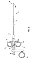
biopsy forceps 10 is shown in greater detail in Figure 2. Thebiopsy forceps 10 is adapted for use internally of the body, for example in connection with endoscopic, laparoscopic or vascular procedures.Forceps 10 includes acontrol handle portion 12 at aproximal end 15, amiddle portion 14 which extends over the main length of the device, and adistal end 16 which includes opposedforceps cutting jaws 120, as is explained in greater detail below. - The main body or length of the
forceps 10 consists of coaxial inner and outertubular members tubular member 22 is small enough such that it can be inserted within a working channel of an endoscope. In one embodiment, theinner tubular member 20 is a stainless steel tube, and the outertubular member 22 or catheter body is a coil. In another embodiment, theinner tubular member 20 comprises a coiled stainless steel tube. For either theinner tubular member 20 or the outertubular member 22 having the coiled stainless steel configuration, the coil is a finely wound spiral coil of stainless steel as is generally known and used in catheters and guidewires. Alternatively, the outertubular member 22 or theinner tubular member 20 could be made using a plastic tube, or a plastic/metal composite structure, in place of the coil. - The
inner tubular member 20 is positioned within the outertubular member 22 and these components are dimensioned with respect to each other so that innertubular member 20 moves freely within the outertubular member 22 to actuate the jaws, as is explained in more detail below. Theinner tubular member 20 has acentral access lumen 28 extending through theinner tubular member 20 from theproximal end 15 to thedistal end 16. Theaccess lumen 28 is sized to receive theoptical fiber 900 therethrough. Theoptical fiber 900, in one embodiment, is removably disposed within theaccess lumen 28. Theaccess lumen 28 is sized larger than theoptical fiber 900, in one embodiment, such that a fluid (e.g. saline) can be flushed through theforceps 10 to clean thelumen 28, the area of interest or to clean the distal portion of theoptical fiber 900. In another embodiment, a variety of medical instruments can be inserted through thelumen 28 when theoptical fiber 900 is removed, as shown in Figures 16a - 16g, and as will be discussed further below. Theinner tubular member 20 is coupled with anactuator housing 60. - The
actuator housing 60, shown in more detail in Figures 4a and 4b is, in one embodiment, fabricated from stainless steel material. Alternatively, theactuator housing 60 can be formed from other substantially rigid materials. Theactuator housing 60 extends from afirst end 62 to asecond end 64, and generally comprises an elongate cylinder. In addition, theactuator housing 60 hasflats 66 formed proximate thefirst end 62. Disposed on theflats 66 arecam pins 68 having a generally circular cross-section, as shown. In one embodiment, the cam pins 68 are integral with theflats 66 of theactuator housing 60. To form the cam pins 68 integrally with theflats 66, theactuator housing 60 can be machined or molded from a single piece of material. Alternatively, the cam pins 68 can be integrally formed with theflats 66 by attaching the projections to theflats 66 using, for example, adhesive or welding processes. The cam pins 68 are for coupling with the jaws, as will be further explained below. - The
actuator housing 60 has abore 70 extending from thefirst end 62 to thesecond end 64, where the bore has afirst portion 72 and asecond portion 74. The first andsecond portions shoulder 76 in between. Thefirst portion 72 has a smaller diameter than theinner tubular member 20, yet large enough to allow theoptical fiber 900 to pass through thefirst portion 72. In one embodiment, thefirst portion 72 is large enough to allow other medical devices to pass through, such as the devices shown in Figures 16a - 16g. Theinner tubular member 20 is inserted within thesecond portion 74 of theactuator housing 60 until, in one embodiment,inner tubular member 20 contacts theshoulder 76 of theactuator housing 60. In another configuration, theinner tubular member 20 can be placed proximate toshoulder 76. Theaccess lumen 28 of theinner tubular member 20 is substantially aligned with thebore 70 of theactuator housing 60, thereby facilitating insertion of theoptical fiber 900 or the medical devices through theaccess lumen 28 and through thebore 70. Theinner tubular member 20 is coupled with theactuator housing 60, where in one embodiment, theinner tubular member 20 is secured to theactuator housing 60 with aweld 78. Alternatively, theinner tubular member 20 can be joined with theactuator housing 60 by solder, brazing, or adhesive techniques as is known by those skilled in the art. - Figures 3, 5a and 5b show the cutting
jaws 120 in more detail. The cuttingjaws 120 are comprised of afirst jaw 122 and asecond jaw 124 which, in one embodiment, are mirror images of each other. Since thefirst jaw 122 and thesecond jaw 124 are similar, only thefirst jaw 122 will be discussed. Thejaw 122 has anactuation portion 132 and a cuttingportion 136. Within the cuttingportion 136, thejaw 122 has ahemispherical cup 126 with sharpenededges 130 for taking biopsy samples. Thecup 126 ofjaw 122 has, in one embodiment, ahole 128 disposed therein. Thehole 128 advantageously facilitates cutting the biopsy sample at the site within the body, and also facilitates the removal of the biopsy specimens captured by eachcup 126. - Referring to the
actuation portion 132, thejaw 122 has a cut out 138 for forming a pivot point for thejaw 122. The cut out 138 is generally circular in shape and sized to receive a projection of a distal housing, as will be further discussed below. Theactuation portion 132 also includes acam slot 140, which in one embodiment is arcuately shaped. Thecam slot 140 couples with thecam pin 68 of theactuator housing 60. Thecam slot 140 is sized to receive thecam pin 68 therein, and allows for radial movement of thejaw 122 about the pivot point as thecam pin 68 of theactuator housing 60 is moved along the axis of thebiopsy forceps 10. The movement of thejaw 122 about the pivot point allows for radial movement of the cuttingjaws 120, without axial movement of the cuttingjaws 120. This provides a further benefit since the jaws more accurately cut the biopsy sample at the exact position identified using theoptical fiber 900. -
Biopsy forceps 10 also includes adistal housing 90, as shown in more detail in Figure 6. Thedistal housing 90 is a generally elongate cylinder having aradial axis 106 and extending from afirst end 92 to asecond end 94. Thehousing 90 is fabricated from, in one embodiment, stainless steel material. Disposed proximate thefirst end 92 areflats 96. In one embodiment, theflats 96 each form a surface which is parallel to each other. Theflats 96 each have apivot pin 100 disposed thereon. Thepivot pin 100 couples with the cut out 138 in each of the cuttingjaws 120, and allows the cuttingjaws 120 to rotate about thepivot pin 100. Theflats 96 have a cut out 98 extending through thehousing 90. In one embodiment, the cut out 98 is generally square shaped and is disposed perpendicular to theradial axis 106 of thehousing 90, as shown in Figure 6. The cut out 98 is sized to allow theactuator housing 60 to travel along theradial axis 106 of thehousing 90 sufficient to actuate the cuttingjaws 120 without interference from thedistal housing 90. - Extending through the
housing 90 is abore 102. Thebore 102 is aligned with theradial axis 106 of thehousing 90 and extends from thefirst end 92 to thesecond end 94. Thebore 102 has its largest diameter proximate thesecond end 94, and tapers to asecond bore portion 108. Thehousing 90 has athird bore portion 110 proximate thefirst end 92 of thehousing 90. Thebore 102 is sized to receive the outertubular member 22 therein. The outertubular member 22 is secured to thehousing 90 by welding, brazing, soldering, adhesives, or other equivalents known to those skilled in the art. Thesecond bore portion 108 is sized to receive theactuator housing 60 therethrough, and to allow theactuator housing 60 to travel axially to actuate thejaws 120. Thethird bore portion 110 is sized to freely receive theoptical fiber 900 or medical devices such as those shown in Figures 16a - 16g, such that thefiber 900 or the devices can be used through the cuttingjaws 120. - Referring again to Figure 1, the
biopsy forceps 10 includes thehandle portion 12 for facilitating actuation of theinner tubular member 20. Thehandle portion 12 includes ahandle 42 and atranslation member 46, andloops Loops handle portion 12 to form finger holes useful in grasping and manipulating theforceps 10. Thehandle 42 is fastened to the translation member with afastener 44. Theinner tubular member 20 is fastened to the translation member by welding, brazing, soldering, adhesives, or other mechanical fasteners such that movement of thehandle 42 results in movement of theinner tubular member 20. In addition, a luer fitting 48 is threaded into thetranslation member 46. Thetranslation member 46 has a bore (not shown) therethrough, which provides a conduit between the luer fitting 48 and theinner tubular member 20. The luer fitting 48 in combination with the bore of thetranslation member 46 provide access to thelumen 28 and allows for ease of cleaning and reusability of thebiopsy forceps 10. Thehandle portion 12 can include any type of actuating mechanism capable of imparting bidirectional axial movement to theinner tubular member 20 ofbiopsy forceps 10. - Referring to Figures 1 and 2, in operation, the
handle 42 is retracted toward the back ofhandle portion 12 to close the jaws. Retraction of thehandle 42 causes movement of theinner tubular member 20 and theactuator housing 60 toward thehandle portion 12, and closes the cuttingjaws 120. In this configuration, thedistal end 16 of theforceps 10 is of the same narrow diameter as the main body of a forceps catheter, and the closed jaws have a smooth, rounded shape to facilitate introduction and navigation in the vascular, endoscopic or laparoscopic systems. In addition, the cutting jaws are coaxially positioned with respect to the distal end of theinner tubular member 20. - The endoscopist advances the
biopsy forceps 10 through a working channel of the endoscope to the general area of interest, i.e., such as a tissue site. Once in place in the general area of interest, the forceps jaws can be opened by advancing thehandle 42 toward thedistal end 16 of theforceps 10, thereby advancing the translatingmember 46 away from thehandle 42. This causes theinner tubular member 20 to move away from thehandle 42, which in turn causes theactuator housing 60 to be axially moved towards thedistal end 16 of the forceps. As theactuator housing 60 moves, the cam pins 68 on theactuator housing 60 move within thecam slots 140 of the cuttingjaws 120, causing the cuttingjaws 120 to open. - When a biopsy area is identified by the
optical fiber 900 using spectrophotometric analysis and/or selected by other methods, the area can now be treated through the lumen using various medical instruments, flushed with saline, or treated with medicine. If other medical instruments are necessary, theoptical fiber 900 is removed from thelumen 28, and a new instrument is inserted therein. If a biopsy of the area is necessary, thehandle 42 is retracted toward theproximal end 15 of theforceps 10, retracting theinner tubular member 20, and causing the cuttingjaws 120 to close and cut a biopsy sample at the exact place that had been treated and/or identified. To take the tissue sample, the endoscopist holding the instrument by thehandle portion 12, gently pulls back on thehandle 42, retracting theinner tubular member 20, and closing the cuttingjaws 120 on the biopsy sample. When thejaws 120 are closed, the endoscopist pulls the entire assembly away from the tissue surface and out of the body. To retrieve the specimen sample from the cuttingjaws 120, an instrument is inserted into thehole 128 in thehemispherical cup 126 of one of the cuttingjaws 120 or the cuttingjaws 120 can be flushed with saline to remove the sample. - Referring to Figure 7, another embodiment of a biopsy forceps of the present invention is generally indicated by
reference number 200. Thebiopsy forceps 200 is generally similar to thebiopsy forceps 10 shown in Figure 1, and accordingly, corresponding elements have been given the same reference number. The biopsy forceps is adapted for use internally of the body, for example in connection with endoscopic, laparoscopic or vascular procedures. Theforceps 200 includes ahandle portion 12 at theproximal end 15, amiddle portion 14 which extends over the main length of the device, and adistal end 16. Thedistal end 16 includesforceps cutting jaws 120. - The
forceps 200 has a coaxialinner member 220 and an outertubular member 222, as shown in Figure 8. The outertubular member 222 and theinner member 220 each extend generally from theproximal end 15 to thedistal end 16 of theforceps 200. The outertubular member 222, in one embodiment, comprises a finely wound spiral coil of stainless steel as is generally known and used in catheters and guidewires. Alternatively, the outertubular member 222 could be made using a plastic tube, or a plastic/metal composite structure, in place of the stainless steel spiral coil. The outertubular member 222 has a lumen therethrough which is sized to received theinner member 220 therein. - In one embodiment, the
inner member 220 comprises a polymer tube which is extruded with alumen 230 therein. Alternatively, theinner member 220 comprises a plastic tube or a combination of metal and plastic. Thelumen 230 is sized to receive anoptical fiber 250 therein. Secured to at least a portion of theoptical fiber 250, theinner member 220 forms a cladding for theoptical fiber 250. In addition,grooves inner member 220. Thegrooves inner member 220 and can also take the form of an indentation or a lumen. In another embodiment, thegrooves lumen 230. Positioned within thegrooves inner member 220 are a pair ofcontrol wires tubular member 222 andinner member 220 extend over the main length of the device, from thedistal end 16 to the handle portion 12 (Figure 7). - The
handle portion 12 includes a translatingmember 244, which in one embodiment, comprises an aluminum block. Thehandle 242 is fastened to thetranslation member 244 withfastener 44. Both theinner member 220 and thecontrol wires member 244, shown in more detail in Figure 9. The translatingmember 46 has aprojection 246 for securing theinner member 220 with thehandle 242. Theprojection 246, comprising a generally elongate cylinder, hasridges projection 246. Theridges projection 246 engage thelumen 230 of theinner member 220 and prevent theinner member 220 from disengaging from thehandle 242. Thecontrol wires member 244 by either welding, soldering, brazing, adhesives, a mechanical fastener, or other alternatives as known by those skilled in the art. - The
inner member 220 and thecontrol wires member 244 which together, in one embodiment, form an actuator mechanism for theforceps 200. Movement of translatingmember 244 causes axial movement of theinner member 220 and thecontrol wires tubular member 222, which is used to actuate the cuttingjaws 120.Loops handle portion 12 to form finger holes useful in grasping and manipulating the forceps 200 (Figure 7). - The
inner member 220 extends from thehandle portion 12 to thedistal end 16. Coupled to theinner member 220 and thecontrol wires distal end 16 is anactuator housing 260. Theactuator housing 260, shown in more detail in Figure 10 is, in one embodiment, fabricated from stainless steel material, and generally comprises an elongate cylinder. Theactuator housing 260 extends from afirst end 262 to asecond end 264, and hasflats 266 formed proximate thefirst end 262. Disposed on theflats 266 arecam pins 268 having a generally circular cross-section, as shown. In one embodiment, the cam pins 268 are integral with theflats 266 of theactuator housing 260. To form the cam pins 268 integrally with theflats 266, theactuator housing 260 can be machined or molded from a single piece of material. Alternatively, the cam pins 268 can be integrally formed with theflats 266 by attaching the cam pins 268 to theflats 266 using, for example, adhesive or welding processes. The cam pins 268 are for coupling with thejaws 120, as will be further explained below. - The
actuator housing 260 has abore 270 which extends through theactuator housing 260 from thefirst end 262 to thesecond end 264 and is sized to receive theoptical fiber 250 therethrough. Thebore 270 of theactuator housing 260 aligns with thelumen 230 of theinner member 220 so that access to thedistal end 16 is not prevented. Thebore 270 allows for theoptical fiber 250 to be inserted through the innertubular member 220 and through theactuator housing 260 to the cuttingjaws 120. - The
actuator housing 260 has attachment features so that theinner member 220 can be coupled with theactuator housing 260. In one embodiment, theactuator housing 260 hasridges 272 disposed about the perimeter of theactuator housing 260, proximate to thesecond end 264. Theridges 272 engage the surface of thelumen 230 to retain theinner member 220 on theactuator housing 260. Alternatively, theactuator housing 260 can be coupled with theinner member 220 in other manners, for example, adhesives. Thecontrol wires actuator housing 260. In one embodiment, thecontrol wires reference number 255 by either welding, soldering, brazing, adhesives, or a mechanical fastener. During use, both theactuator housing 260 and thecontrol wires actuation portion 132 of the cuttingjaws 120. - The
biopsy forceps 200 has a distal housing having the same structure as discussed above, and as shown in Figure 6. The outertubular member 222 of thebiopsy forceps 200 is secured to the housing, as in the previous embodiment, and therefore will not be further discussed. Thebiopsy forceps 200 also includes cuttingjaws 120. - The cutting
jaws 120 are also the same as in the previous embodiment, and one of the cuttingjaws 120 is as shown in Figures 5a and 5b. Referring to theactuation portion 132, thejaw 122 has a cut out 138 and acam slot 140. The cut out 138 forms a stationary pivot point for thejaw 122, and receives the pivot pins 100 of thehousing 90 therein. Thecam slot 140 couples with the cam pins 268 of theactuator housing 260, and allows for radial movement of thejaw 122 about the pivot point as the cam pins 268 of theactuator housing 260 are moved along the axis of thebiopsy forceps 200. A further benefit is obtained since the cuttingjaws 120 do not move axially during the cutting process. Instead, the cuttingjaws 120 rotate about the stationary pivot point. This allows for more precise cutting of the biopsy site identified by the optical fiber. - During operation, referring to Figure 7, the
handle 242 is retracted toward the back ofhandle portion 12 to close the jaws. This causes movement of theinner member 20, thecontrol wires actuator housing 260 toward thehandle portion 12, and closes the cuttingjaws 120. In this configuration, thedistal end 16 of theforceps 10 is of the same narrow diameter as the main body of a forceps catheter, and the closed jaws have a smooth, rounded shape to facilitate introduction and navigation in the vascular, endoscopic or laparoscopic systems. In addition, the cutting jaws are coaxially positioned with respect to the distal end of the inner tubular member. - Once in place in the general area of interest, the cutting
jaws 120 can be opened by pushinghandle 42 of the control handle forward, away from thehandle portion 12. This causes movement of thetranslation member 244, theinner member 220, thecontrol wires actuator housing 260 away from thehandle portion 12. Thecontrol wires inner member 220 push against theactuator housing 260. As theactuator housing 260 moves away from thehandle portion 12, the cam pins 268 on theactuator housing 260 move within thecam slots 140 of the cuttingjaws 120, and cause thejaws 120 to open. Thedistal end 16 of theforceps 10 is positioned at the area of contact. Theoptical fiber 250, when connected to the electro-optic diagnostic apparatus, can then be used for optical biopsy to perform histopathological analysis of the tissue site. When an area of disease is identified and a biopsy of the area is needed, thehandle 242 is pulled toward theproximal end 15 of theforceps 10, causing thejaws 120 to close and cut a biopsy sample. The biopsy sample is cut from the exact tissue site identified as the biopsy site without requiring moving or repositioning of the catheter body. The forceps may then be withdrawn from the patient to recover the sample for analysis. The analysis of the withdrawn sample can be conducted using known laboratory techniques to confirm the identification of the tissue sample. - Figure 11 illustrates another embodiment of an
optical biopsy forceps 280. Theoptical biopsy forceps 280 includes cuttingjaws 304, a coaxialinner member 276 and an outertubular member 278 which each extend proximate the distal end of theforceps 280. In one embodiment, theinner member 276 is extruded with alumen 282 therein. Alternatively, theinner member 276 comprises a plastic tube or a combination of metal and plastic. Thelumen 282 is sized to receive anoptical fiber 900 therein. - The inner
tubular member 276 is positioned within the outertubular member 278 and these components are dimensioned with respect to each other so that innertubular member 276 moves freely within the outertubular member 278 to actuate thejaws 304. Theoptical fiber 900, in one embodiment, is removably disposed within thelumen 282. The innertubular member 276 is coupled with anactuator housing 290 such that movement of the innertubular member 276 causes movement of theactuator housing 290. - The
actuator housing 290 is, in one embodiment, fabricated from stainless steel material. Alternatively, theactuator housing 290 can be formed from other substantially rigid materials. Theactuator housing 290 includes at least onepin 292. Thepins 292 are adapted to couple with alink coupling 297 of a first andsecond link - The
actuator housing 290 has abore 294 therethrough, which allows passage of theoptical fiber 900 therethrough. Thebore 294 of theactuator housing 290 is aligned with thelumen 282 of the innertubular member 276, thereby facilitating insertion of theoptical fiber 900, or other medical device through theaccess lumen 282 and through thebore 294. The innertubular member 276 is coupled with theactuator housing 290, where in one embodiment, the innertubular member 276 is secured to theactuator housing 290 with a weld. Alternatively, the innertubular member 276 can be joined with theactuator housing 290 by solder, brazing, or adhesive techniques. - The cutting
jaws 304 are comprised of afirst jaw 306 and asecond jaw 308. The cuttingjaws 304 each have a cut out for forming a pivot point for eachjaw 304. The cut out is generally circular in shape and sized to receive a projection of adistal housing 284, as will be further discussed below. The cuttingjaws 304 each have acoupling 312 for attaching thejaws 304 with alink coupling 297 the first andsecond links coupling 312 comprises alug 314 disposed on thejaws 304, which couples with thelink coupling 297 of the first andsecond links - The
forceps 280 also includes adistal housing 284. Thedistal housing 284 includes at least onepivot pin 286 disposed thereon. Eachpivot pin 286 is adapted to couple with the cut out in each of the cuttingjaws 304, and allows the cuttingjaws 304 to rotate about thepivot pin 286. Thedistal housing 284 has alumen 288 therein which allows passage of theoptical fiber 900 therethrough. - In an alternative embodiment, control wires (See Figures 7 - 9) could be coupled with the first and
second links second links jaws 304 about the pivot pins 286. In addition, the innertubular member 276 would be directly coupled with thedistal housing 284. - During operation, the handle 42 (Figures 1 and 2) is retracted to close the
jaws 304. Retraction of thehandle 42 causes axial movement of the innertubular member 276 and theactuator housing 290 toward thehandle 42, and closes the cuttingjaws 304. After the endoscopist advances thebiopsy forceps 280 through a working channel of the endoscope to the general area of interest, thejaws 304 can be opened by advancing thehandle 42 toward the distal end of theforceps 280. Advancing thehandle 42 causes the innertubular member 276 to move away from thehandle 42, which in turn causes theactuator housing 290 to be axially moved towards the distal end of the forceps. As theactuator housing 290 moves, the first andsecond links jaws 304 causing the first andsecond links actuator housing 290 and thejaws 304. As the links rotate, the cuttingjaws 304 rotate about the pivot pins 286 on thedistal housing 284 and move to an open position. - The above described embodiment provides many advantages over conventional forceps. For instance, the
inner member 220 and thecontrol wires 240, 241 (Figures 7) both actuate the radial movement of the cuttingjaws 120. The combination of devices allows the operator to apply more axial force to theinner member 220 and thecontrol wires jaws 120. The additional torque provides better cutting actuation, particularly in biopsy sites with tissue that is difficult to cut with the relativelysmall cutting jaws 120. Another advantage of this embodiment is that the biopsy forceps is disposable, although the biopsy forceps can be reusable. Forming theinner member 220 from the polymer material helps to provide aninexpensive forceps 10 for disposal after use. In addition, using disposable biopsy forceps eliminates the chance of contamination between patients where a biopsy forceps is disposed after use on one patient, which is ideal for patients with highly contagious and dangerous diseases or patients highly susceptible to infection. - Figures 12a and 12b illustrate yet another embodiment of the present invention. A
biopsy forceps 300 is provided having multiple access lumens. The general configuration of thebiopsy forceps 300 is the same as the first discussed embodiment where an innertubular member 320 is slidably received by an outertubular member 340. The innertubular member 320 actuates the cuttingjaws 120, as discussed above. In one embodiment, the innertubular member 320 has a plurality of lumens disposed therein. In at least one of the lumens, an optical fiber is disposed therethrough. The plurality of lumens allow for other components or materials (such as fluids) to be inserted through the inner tubular member simultaneously with the optical fiber. Alternatively, in another embodiment, agap 316 between the inner surface of the outer tubular member and the outer surface of the innertubular member 320 provides asecondary lumen 318. Thesecondary lumen 318 allows for fluids such as saline or medicine to be administered to the biopsy area. During use, the fluids travel through thesecondary lumen 318 and are expelled through openings between thedistal housing 90 and the cutting jaws 120 (Figure 3) to treat the biopsy area. Access to the primary lumen is at aprimary port 334. To access thesecondary lumen 318 or the multiple lumens described above, asecondary port 332 is provided proximate thehandle portion 12. The secondary port, in one embodiment, comprises a luer fitting as known by those skilled in the art. - Figures 13 and 14 illustrate another embodiment of the present invention. In this configuration, a
biopsy forceps 400 are provided with cuttingjaws 480, ahandle portion 412, and amain body 414 in between. Themain body 414 has an innertubular member 420, which actuates the cuttingjaws 480 and is disposed within an outertubular member 422, as discussed above. Disposed within the innertubular member 420 is anoptical fiber 450. A thirdtubular member 424 is coupled with themain body 420. In one embodiment, the thirdtubular member 424 is secured to the outer surface of the outertubular member 422 as shown in Figure 14 by welding, brazing, soldering, or adhesive. In another embodiment, a polymer heat-shrink jacket 426 is placed over the outertubular member 422 and the thirdtubular member 424 to thereby couple the thirdtubular member 424 with the outertubular member 422. The outer jacket coating provides theforceps 400 with a smooth surface for ease of use within the patient. - In another embodiment of the invention, the
above biopsy forceps 500 are provided with electro-cauterizing capability. In this configuration shown in Figures 15a and 15b, using thebiopsy forceps 500 as described above, aconnector pin 510 is provided on thehandle portion 12. Theconnector pin 510 forms an electrical connection which is compatible with standard electro/surgical equipment. In one embodiment, aprotective collar 522 surrounds theconnector pin 510, preventing inadvertent contact with theconnector pin 510. Thecollar 522 protects theconnector pin 510 from being damaged. The innertubular member 520 comprises a stainless steel tube, which is coupled with theconnector pin 510. Alternatively, the innertubular member 520 comprises a polymer tube with steel control wires, as described above. During use, a radio frequency current is coupled with theconnector pin 510. Theconnector pin 510 allows a current path to the stainless steel tube, or the stainless steel pull wire, depending on the embodiment. The current path would follow the stainless steel tube or wires to the cutting jaws disposed at the distal end of the biopsy forceps. Thejacket 426 acts as an insulator over the length of theforceps 500, with the metallic jaws acting as the cauterizing device. Theconnector pin 510, as known by those skilled in the art, is coupled with equipment having the electro-surgical standard for radio frequency current. The radio frequency current allows for cauterizing capability of thebiopsy forceps 500 in the biopsy site using either mono or bipolar modes. - The lumen of the above biopsy forceps allows for a number of medical instruments to be inserted through the biopsy forceps once the optical fiber is removed, and the instruments are also axially aligned with the cutting jaws. Another embodiment of the present invention includes medical devices slidably engaged within the
access lumen 630 ofbiopsy forceps 600. As shown in Figures 16a - 16e, many instruments can be inserted into thelumen 630 of the inner tubular member 620, including, but not limited to:ultrasonic probe 710,guidewires 712, asnare 714, acytology brush 716, and aneedle 718. In addition, the area to be sampled by thebiopsy forceps 600 can be flushed withsaline 720, medicine, or other fluids as shown in Figure 16f. Alternatively, suction can be applied to thelumen 630 for removing excess loose material or fluid from the biopsy site. As shown in Figure 16g, each instrument is inserted into anaccess port 650 and extends through a translatingmember 646, through amiddle portion 675, and through cuttingjaws 680 of theforceps 600. The instruments are used for treating the tissue in the area adjacent the distal end of theforceps 600, which is aligned with the axis of thelumen 630. - The present invention has provided a biopsy forceps having an access lumen and an optical fiber. An important feature of the invention is that the lumen of the inner tubular member is coaxial with the zone where the two jaws intersect and the sample is taken. Thus, there is no offset error between the spot where the various medical instruments or treatments are used and the spot from which the biopsy sample will be taken. In addition, the physician has more options in treating the area where the biopsy sample is taken. For instance, the area can first be flushed with saline, or treated with medicine. The biopsy forceps provides a further advantage in that an area can be treated with saline and/or with medicine without having to remove the biopsy forceps from the body. Alternatively, one of many instruments can be used to treat the biopsy area prior to the biopsy. These features, together with the slim and compact profile of the device when the jaws are retracted, are a great improvement over prior art devices. One of the advantages of
forceps 10 as compared toforceps 200 is, because thecontrol wires - A further advantage of the present invention is that since the
optical fiber 900 is removable from thebiopsy forceps 10, thebiopsy forceps 10 is reusable. When theoptical fiber 900 needs to be replaced, theentire biopsy forceps 10 does not need to be discarded. Instead, a newoptical fiber 900 is inserted through thecentral access lumen 28 when the use of the previousoptical fiber 900 is exhausted. Removing theoptical fiber 900 from thebiopsy forceps 10 also allows for theforceps 10 to be cleaned and sterilized more extensively using more strenuous processes. In some sterilization techniques, theoptical fiber 900 degrades during the cleaning process. Thus, removing thefiber 900 during the more strenuous cleaning processes prolongs the useful life of theoptical fiber 900. - It will be appreciated from the foregoing that we have provided an improved biopsy forceps and system which provides the physician a greater degree of accuracy and control over the biopsy treatment and sampling process than was previously possible. While we have illustrated the invention with the illustrated embodiments of the invention, it will be appreciated that variations of shapes, materials and assembly are possible, within the scope of the invention.
- It is to be understood that the above description is intended to be illustrative, and not restrictive. Many other embodiments will be apparent to those of skill in the art upon reviewing the above description. The scope of the invention should, therefore, be determined with reference to the appended claims, along with the full scope of equivalents to which such claims are entitled.
Claims (35)
- A biopsy forceps (10) for sampling tissue from an area of interest, the biopsy forceps comprising:a flexible outer tubular member (22) having a first lumen (318) therethrough, the outer tubular member extending from the proximal end to the distal end and adapted for insertion into a working channel of an endoscope;cutting jaws (122,124) mounted proximate to the distal end of the outer tubular member for selective opening and closing in a biopsy cutting movement, the cutting jaws mounted with a closed cutting position co-axially aligned with the first lumen;an inner tubular member (20) having a second lumen (28) therethrough, the inner tubular member extending through the first lumen of the outer tubular member and operatively connected to open and close the cutting jaws;an actuator mechanism (60) coupled with the respective distal ends of the outer tubular member (22) and the inner tubular member (20);an access port (334,650) communicatively coupled with the second lumen (28); andwherein the actuator mechanism (60) is coupled with the inner tubular member (20) such that actuating the actuator mechanism causes axial translation of the inner tubular member thereby causing closing and opening movement of the cutting jaws (112,124).
- The biopsy forceps of claim 1, wherein the second lumen (28) is adapted for flushing the area of interest.
- The biopsy forceps of claim 1, wherein the second lumen is adapted for suctioning the area of interest.
- The biopsy forceps of claim 2 or claim 3, further comprising a medical instrument (710,712,714,716,718,900) removably disposed within the second lumen (28) of the inner tubular member (20) extending from a proximal end to a distal end, the medical instrument adapted for use in the area of interest to treat a biopsy sampling area, the forceps being adapted to provide accurate alignment with repetitive introduction and withdrawal of medical instruments during use.
- The biopsy forceps of claim 4, wherein the medical instrument comprises an ultrasonic probe (710).
- The biopsy forceps of claim 4, wherein the medical instrument comprises an optical fiber (900).
- The biopsy forceps of claim 4, wherein the medical instrument comprises at least one guidewire (712).
- The biopsy forceps of claim 4, wherein the medical instrument comprises a snare (714).
- The biopsy forceps of claim 4, wherein the medical instrument comprises a cytology brush (716).
- The biopsy forceps of claim 4, wherein the medical instrument comprises a needle (718).
- A biopsy forceps according to claim 6, wherein the optical fiber (900) is removably disposed within the second lumen (28) of the inner tubular member (20), the optical fiber extending from a proximal end to a distal end, said proximal end of the optical fiber being adapted for connection to a spectrophotometric tissue analysis system, and said optical fiber being removable during use of the biopsy forceps.
- A biopsy forceps according to claim 11, wherein movement of the inner tubular member causes radial movement of the cutting jaws about fixed pivot pins (100), said cutting jaws being pivotally mounted to pivot about a common pivotal axis.
- A biopsy forceps according to claim 11, wherein the outer tubular member (22) comprises a coiled stainless steel tube.
- A biopsy forceps according to claim 11, wherein the inner tubular member (20) comprises a coiled stainless steel tube.
- A biopsy forceps according to claim 11, wherein the biopsy forceps further comprises an actuator housing having a bore coaxially aligned with the second lumen (28), and the actuator housing is coupled with the distal end of the inner tubular member (20) for actuating the cutting jaws (122,124).
- A biopsy forceps according to claim 11, wherein the second lumen (28) of the inner tubular member (20) has a first diameter and an outer diameter of the optical fiber (900) has a second diameter, and the first diameter is greater than the second diameter and adapted for fluid to be flushed therethrough.
- A biopsy forceps according to claim 11, and further comprising an electrical connection (510) in the proximal end electrically connected for cauterizing tissue proximate the distal end of the forceps via electrosurgical current.
- A biopsy forceps according to claim 11, and further comprising a handle portion (12) coupled with the proximal end of the outer tubular member and the inner tubular member, the handle portion comprising:a handle (42); anda translating member (46) operatively coupled with the handle (42) and the inner tubular member (20), where moving the handle causes axial movement to the inner tubular member to open and close the cutting jaws.
- A biopsy forceps according to claim 18, wherein the forceps further comprises an actuator housing (60) operatively coupled with the inner tubular member (20) and the cutting jaws (122,124), and a distal housing (90) coupled with the cutting jaws and the outer tubular member (22).
- A biopsy forceps according to claim 19, wherein the actuator housing (60) has at least two cam pins (68) integral therewith, the cutting jaws each have a cam slot (140), the distal housing has two coaxial pivot pins (100) integral therewith, and the actuator housing cam pins (68) are received by respective cam slots (140) of the cutting jaws wherein axial movement of the cam pins (68) causes pivoting movement of the cutting jaws about the pivot pins (100), said cutting jaws pivotally mounted to pivot about a common pivotal axis.
- A biopsy forceps according to claim 19, wherein the actuator housing (60) comprises at least a first link (296) and a second link (298) rotatably coupled with the cutting jaws and the actuator housing, and the distal housing having at least one pivot pin (286) integral therewith, where the cutting jaws are adapted to rotate about the pivot pins, said cutting jaws pivotally mounted to pivot about a common pivotal axis.
- A biopsy forceps according to claim 1 or claim 12, wherein the inner tubular member has at least one groove (232,234) disposed therein; and the forceps further comprises:at least one control wire (240,241) disposed in at least one of the grooves of the inner member and extending from the proximal end to the distal end, where the control wire and the inner member (20) are operatively coupled with the cutting jaws such that axial movement of the control wire and the inner member causes pivoting movement of the cutting jaws about stationary pivot pins (100).
- A biopsy forceps according to claim 22, wherein the inner member (20) has two grooves (232,234) each disposed in an outer surface of the inner member, and each groove has a control wire (240,241) disposed therein.
- A biopsy forceps according to claim 22, wherein the inner member (20) comprises a polymer tube.
- A biopsy forceps according to claim 22, wherein the forceps further comprises an actuator housing (60) operatively coupled with the inner tubular member (20) and the cutting jaws (122,124), and a distal housing (90) coupled with the cutting jaws (122,124) and the outer tubular member (22).
- A biopsy forceps according to claim 25, wherein the actuator housing has at least two cam pins (68) integral therewith, the cutting jaws each have a cam slot (140), the distal housing has pivot pins (100) integral therewith, and the actuator housing cam pins (68) are received by the cam slots (140) of the cutting jaws wherein movement of the cam pins causes radial movement of the cutting jaws about the pivot pins about a common pivotal axis.
- A biopsy forceps according to claim 11, further comprising:a third tubular member (424) coupled with an outer surface of the outer tubular member (422), the third tubular member extending from the proximal to the distal ends and having a third lumen therein; anda second access port coupled with the proximal end of the third tubular member.
- A biopsy forceps according to claim 27, wherein the forceps further comprises shrink tubing (426) disposed over the third tubular member and the outer tubular member.
- A biopsy forceps according to any of claims 1 to 9, wherein the actuator mechanism comprises:a handle portion coupled with the proximal end of the outer tubular member and the inner tubular member, the handle portion comprising:a handle (42);a translating member (46) operatively coupled with the handle (42) and the inner tubular member (20), where moving the handle causes axial movement to the inner tubular member to open and close the cutting jaws.
- A biopsy forceps according to claim 29, wherein the forceps further comprises an actuator housing (60) operatively coupled with the inner tubular member (20) and the cutting jaws (122,124), and a distal housing (90) coupled with the cutting jaws (122,124) and the outer tubular member (22).
- A biopsy forceps according to claim 30, wherein the actuator housing has at least two cam pins (68) integral therewith, the cutting jaws each have a cam slot (140), the distal housing (90) has pivot pins (100) integral therewith, and the actuator housing cam pins (68) are received by the cam slots (140) of the cutting jaws wherein movement of the cam pins causes radial movement of the cutting jaws about the pivot pins, about a common pivotal axis.
- A biopsy forceps according to claim 30, wherein the actuator housing (60) comprises at least a first link (296) and a second link (298) rotatably coupled with the cutting jaws (122,124) and the actuator housing (60), and the distal housing has pivot pins (100) integral therewith, where the cutting jaws are adapted to rotate about the pivot pins, about a common pivotal axis.
- A biopsy forceps according to claim 18 or claim 32, wherein the biopsy forceps further comprises at least one Luer fitting (48) communicatively coupled with the second lumen (28) of the inner tubular member (20).
- A biopsy forceps according to claim 18 or claim 32, wherein each cutting jaw has a cup portion (126) for receiving the biopsy sample therein, and at least one cup portion has an aperture (128) therein, wherein said aperture facilitates the removal of biopsy samples from the cup of the cutting jaws.
- A biopsy forceps according to claim 6 or claim 18, wherein the inner tubular member has at least two lumens therein, and the optical fiber (900) is disposed in one of the lumens.
Applications Claiming Priority (3)
| Application Number | Priority Date | Filing Date | Title |
|---|---|---|---|
| US37240 | 1998-03-09 | ||
| US09/037,240 US6066102A (en) | 1998-03-09 | 1998-03-09 | Optical biopsy forceps system and method of diagnosing tissue |
| PCT/US1999/005118 WO1999045847A1 (en) | 1998-03-09 | 1999-03-08 | Optical biopsy forceps system and method of sampling tissue |
Publications (2)
| Publication Number | Publication Date |
|---|---|
| EP1063921A1 EP1063921A1 (en) | 2001-01-03 |
| EP1063921B1 true EP1063921B1 (en) | 2007-02-14 |
Family
ID=21893242
Family Applications (1)
| Application Number | Title | Priority Date | Filing Date |
|---|---|---|---|
| EP99909933A Expired - Lifetime EP1063921B1 (en) | 1998-03-09 | 1999-03-08 | Optical biopsy forceps system |
Country Status (7)
| Country | Link |
|---|---|
| US (2) | US6066102A (en) |
| EP (1) | EP1063921B1 (en) |
| JP (1) | JP4361683B2 (en) |
| AT (1) | ATE353594T1 (en) |
| CA (1) | CA2322775C (en) |
| DE (1) | DE69935132D1 (en) |
| WO (1) | WO1999045847A1 (en) |
Cited By (7)
| Publication number | Priority date | Publication date | Assignee | Title |
|---|---|---|---|---|
| US7952718B2 (en) | 2007-05-03 | 2011-05-31 | University Of Washington | High resolution optical coherence tomography based imaging for intraluminal and interstitial use implemented with a reduced form factor |
| US8382662B2 (en) | 2003-12-12 | 2013-02-26 | University Of Washington | Catheterscope 3D guidance and interface system |
| US8396535B2 (en) | 2000-06-19 | 2013-03-12 | University Of Washington | Integrated optical scanning image acquisition and display |
| US8537203B2 (en) | 2005-11-23 | 2013-09-17 | University Of Washington | Scanning beam with variable sequential framing using interrupted scanning resonance |
| US8840566B2 (en) | 2007-04-02 | 2014-09-23 | University Of Washington | Catheter with imaging capability acts as guidewire for cannula tools |
| US9161684B2 (en) | 2005-02-28 | 2015-10-20 | University Of Washington | Monitoring disposition of tethered capsule endoscope in esophagus |
| US9561078B2 (en) | 2006-03-03 | 2017-02-07 | University Of Washington | Multi-cladding optical fiber scanner |
Families Citing this family (221)
| Publication number | Priority date | Publication date | Assignee | Title |
|---|---|---|---|---|
| US6066102A (en) | 1998-03-09 | 2000-05-23 | Spectrascience, Inc. | Optical biopsy forceps system and method of diagnosing tissue |
| US6210330B1 (en) * | 1999-08-04 | 2001-04-03 | Rontech Medical Ltd. | Apparatus, system and method for real-time endovaginal sonography guidance of intra-uterine, cervical and tubal procedures |
| JP3655785B2 (en) * | 1999-10-18 | 2005-06-02 | ペンタックス株式会社 | Endoscopic treatment tool |
| US8888688B2 (en) | 2000-04-03 | 2014-11-18 | Intuitive Surgical Operations, Inc. | Connector device for a controllable instrument |
| US6610007B2 (en) | 2000-04-03 | 2003-08-26 | Neoguide Systems, Inc. | Steerable segmented endoscope and method of insertion |
| US8517923B2 (en) | 2000-04-03 | 2013-08-27 | Intuitive Surgical Operations, Inc. | Apparatus and methods for facilitating treatment of tissue via improved delivery of energy based and non-energy based modalities |
| US6468203B2 (en) | 2000-04-03 | 2002-10-22 | Neoguide Systems, Inc. | Steerable endoscope and improved method of insertion |
| US6858005B2 (en) * | 2000-04-03 | 2005-02-22 | Neo Guide Systems, Inc. | Tendon-driven endoscope and methods of insertion |
| JP4166414B2 (en) * | 2000-05-17 | 2008-10-15 | オリンパス株式会社 | Endoscopic treatment tool |
| JP4241038B2 (en) * | 2000-10-30 | 2009-03-18 | ザ ジェネラル ホスピタル コーポレーション | Optical method and system for tissue analysis |
| US9295391B1 (en) | 2000-11-10 | 2016-03-29 | The General Hospital Corporation | Spectrally encoded miniature endoscopic imaging probe |
| DE10100739B4 (en) * | 2001-01-10 | 2004-04-29 | Aesculap Ag & Co. Kg | Devices for inserting objects into a body |
| DE10118570B4 (en) * | 2001-01-10 | 2004-06-03 | Aesculap Ag & Co. Kg | Surgical device |
| US7699835B2 (en) * | 2001-02-15 | 2010-04-20 | Hansen Medical, Inc. | Robotically controlled surgical instruments |
| EP2333523B1 (en) * | 2001-04-30 | 2020-04-08 | The General Hospital Corporation | Method and apparatus for improving image clarity and sensitivity in optical coherence tomography using dynamic feedback to control focal properties and coherence gating |
| US7865231B2 (en) | 2001-05-01 | 2011-01-04 | The General Hospital Corporation | Method and apparatus for determination of atherosclerotic plaque type by measurement of tissue optical properties |
| US6494845B2 (en) * | 2001-05-04 | 2002-12-17 | Oralscan Laboratories, Inc. | Retractable brush for use with endoscope for brush biopsy |
| WO2003017745A2 (en) * | 2001-08-23 | 2003-03-06 | Sciperio, Inc. | Architecture tool and methods of use |
| JP5073895B2 (en) | 2001-09-25 | 2012-11-14 | オリンパス株式会社 | Endoscopic treatment tool |
| US6980299B1 (en) * | 2001-10-16 | 2005-12-27 | General Hospital Corporation | Systems and methods for imaging a sample |
| US7169167B2 (en) * | 2001-12-04 | 2007-01-30 | Scimed Life Systems, Inc. | Endoscopic apparatus and method |
| US6908476B2 (en) * | 2001-12-21 | 2005-06-21 | Alcon Grieshaber Ag | Micro surgical cutting instrument configured as scissors |
| CN1764416A (en) | 2002-01-09 | 2006-04-26 | 新引导系统公司 | Apparatus and method for endoscopic colectomy |
| CN1617687A (en) * | 2002-01-09 | 2005-05-18 | 新引导系统公司 | Apparatus and method for spectroscopic examination of the colon |
| WO2003060423A2 (en) * | 2002-01-11 | 2003-07-24 | The General Hospital Corporation | Apparatus for low coherence ranging |
| US7355716B2 (en) | 2002-01-24 | 2008-04-08 | The General Hospital Corporation | Apparatus and method for ranging and noise reduction of low coherence interferometry LCI and optical coherence tomography OCT signals by parallel detection of spectral bands |
| DE20205190U1 (en) * | 2002-04-03 | 2002-07-04 | Polydiagnost Gmbh | A biopsy instrument |
| JP4131011B2 (en) * | 2002-04-09 | 2008-08-13 | Hoya株式会社 | Endoscopic sputum treatment device |
| JP2004024331A (en) * | 2002-06-21 | 2004-01-29 | Vayu:Kk | Catheter |
| US7758608B2 (en) * | 2002-07-25 | 2010-07-20 | Dicesare Paul | Enhanced dexterity surgical hand piece |
| US7131977B2 (en) * | 2002-08-27 | 2006-11-07 | Pilling Weck Incorporated | Apparatus and method for removing a clip |
| WO2004088361A2 (en) | 2003-03-31 | 2004-10-14 | The General Hospital Corporation | Speckle reduction in optical coherence tomography by path length encoded angular compounding |
| US8054468B2 (en) | 2003-01-24 | 2011-11-08 | The General Hospital Corporation | Apparatus and method for ranging and noise reduction of low coherence interferometry LCI and optical coherence tomography OCT signals by parallel detection of spectral bands |
| EP2319405B1 (en) * | 2003-01-24 | 2013-09-18 | The General Hospital Corporation | System and method for identifying tissue using low-coherence interferometry |
| US8882657B2 (en) | 2003-03-07 | 2014-11-11 | Intuitive Surgical Operations, Inc. | Instrument having radio frequency identification systems and methods for use |
| JP4131014B2 (en) * | 2003-03-18 | 2008-08-13 | Hoya株式会社 | Endoscopic sputum treatment device |
| WO2004091377A2 (en) * | 2003-03-28 | 2004-10-28 | Downey Earl C | Surgical instrument with trigger control |
| KR101386971B1 (en) * | 2003-06-06 | 2014-04-18 | 더 제너럴 하스피탈 코포레이션 | Process and apparatus for a wavelength tunning source |
| US20050043582A1 (en) * | 2003-06-17 | 2005-02-24 | Stokes Michael J. | Surgical instrument having an increased range of motion |
| US20040260199A1 (en) * | 2003-06-19 | 2004-12-23 | Wilson-Cook Medical, Inc. | Cytology collection device |
| US20080235055A1 (en) * | 2003-07-17 | 2008-09-25 | Scott Mattingly | Laboratory instrumentation information management and control network |
| US7775989B2 (en) * | 2003-09-03 | 2010-08-17 | Granit Medical Innovations, Llc | Needle biopsy forceps with integral sample ejector |
| US7379769B2 (en) | 2003-09-30 | 2008-05-27 | Sunnybrook Health Sciences Center | Hybrid imaging method to monitor medical device delivery and patient support for use in the method |
| US7970452B2 (en) * | 2003-09-30 | 2011-06-28 | Hologic, Inc. | Open architecture imaging apparatus and coil system for magnetic resonance imaging |
| US20080077005A1 (en) * | 2004-08-12 | 2008-03-27 | Piron Cameron A | System and Method for Multimodality Breast Imaging |
| US7908690B2 (en) * | 2003-09-30 | 2011-03-22 | Sentinelle Medical, Inc. | Supine patient support for medical imaging |
| US7733497B2 (en) | 2003-10-27 | 2010-06-08 | The General Hospital Corporation | Method and apparatus for performing optical imaging using frequency-domain interferometry |
| EP1687587B1 (en) * | 2003-11-28 | 2020-01-08 | The General Hospital Corporation | Method and apparatus for three-dimensional spectrally encoded imaging |
| WO2007017949A1 (en) * | 2005-08-11 | 2007-02-15 | Olympus Corporation | Treatment device for endoscope |
| US7922654B2 (en) | 2004-08-09 | 2011-04-12 | Boston Scientific Scimed, Inc. | Fiber optic imaging catheter |
| US11819192B2 (en) | 2004-03-23 | 2023-11-21 | Boston Scientific Scimed, Inc. | In-vivo visualization system |
| ES2409160T3 (en) | 2004-03-23 | 2013-06-25 | Boston Scientific Limited | Live View System |
| DE102004015642B3 (en) * | 2004-03-31 | 2006-02-02 | Siemens Ag | Device for elimination of complete occlusion with OCT monitoring |
| AU2004320269B2 (en) | 2004-05-29 | 2011-07-21 | The General Hospital Corporation | Process, system and software arrangement for a chromatic dispersion compensation using reflective layers in optical coherence tomography (OCT) imaging |
| WO2006005075A2 (en) * | 2004-06-30 | 2006-01-12 | Amir Belson | Apparatus and methods for capsule endoscopy of the esophagus |
| WO2006014392A1 (en) | 2004-07-02 | 2006-02-09 | The General Hospital Corporation | Endoscopic imaging probe comprising dual clad fibre |
| US8081316B2 (en) | 2004-08-06 | 2011-12-20 | The General Hospital Corporation | Process, system and software arrangement for determining at least one location in a sample using an optical coherence tomography |
| US8208995B2 (en) | 2004-08-24 | 2012-06-26 | The General Hospital Corporation | Method and apparatus for imaging of vessel segments |
| WO2006024014A2 (en) | 2004-08-24 | 2006-03-02 | The General Hospital Corporation | Process, system and software arrangement for measuring a mechanical strain and elastic properties of a sample |
| US7365859B2 (en) * | 2004-09-10 | 2008-04-29 | The General Hospital Corporation | System and method for optical coherence imaging |
| EP2329759B1 (en) | 2004-09-29 | 2014-03-12 | The General Hospital Corporation | System and method for optical coherence imaging |
| JP5175101B2 (en) * | 2004-10-29 | 2013-04-03 | ザ ジェネラル ホスピタル コーポレイション | System and method for performing Jones matrix based analysis to measure unpolarized polarization parameters using polarization sensitive optical coherence tomography |
| JP5623692B2 (en) * | 2004-11-02 | 2014-11-12 | ザ ジェネラル ホスピタル コーポレイション | Optical fiber rotator, optical system and method for sample imaging |
| US7995210B2 (en) | 2004-11-24 | 2011-08-09 | The General Hospital Corporation | Devices and arrangements for performing coherence range imaging using a common path interferometer |
| JP2008521516A (en) | 2004-11-29 | 2008-06-26 | ザ ジェネラル ホスピタル コーポレイション | Configuration, apparatus, endoscope, catheter, and method for performing optical image generation by simultaneously illuminating and detecting multiple points on a sample |
| US7854705B2 (en) * | 2004-12-16 | 2010-12-21 | Olga Pawluczyk | Ex vivo verification of biopsy tissue samples |
| ATE440552T1 (en) * | 2005-01-20 | 2009-09-15 | Wilson Cook Medical Inc | BIOPSY FORCEPS |
| EP1863388A1 (en) * | 2005-03-03 | 2007-12-12 | Granit Medical Innovations, LLC | Needle biopsy forceps with integral sample ejector |
| BRPI0609486A2 (en) * | 2005-04-05 | 2010-04-13 | Brigham & Womens Hospital Inc | peroral endoscopic restoration system of a gastric bypass malformation and method for peroral restoration of a malformation resulting from gastric bypass surgery in a patient |
| EP2325803A1 (en) | 2005-04-28 | 2011-05-25 | The General Hospital Corporation | Evaluating optical coherence tomography information for an anatomical structure |
| JP4481922B2 (en) * | 2005-05-13 | 2010-06-16 | オリンパスメディカルシステムズ株式会社 | Medical treatment tool |
| US7762960B2 (en) | 2005-05-13 | 2010-07-27 | Boston Scientific Scimed, Inc. | Biopsy forceps assemblies |
| EP1887926B1 (en) * | 2005-05-31 | 2014-07-30 | The General Hospital Corporation | System and method which use spectral encoding heterodyne interferometry techniques for imaging |
| US9060689B2 (en) | 2005-06-01 | 2015-06-23 | The General Hospital Corporation | Apparatus, method and system for performing phase-resolved optical frequency domain imaging |
| US8052703B2 (en) * | 2005-06-29 | 2011-11-08 | Boston Scientific Scimed, Inc. | Medical devices with cutting elements |
| US20070066867A1 (en) * | 2005-07-19 | 2007-03-22 | University Of Rochester | Bronchoscopic application of therapeutic agent to upper airway and nasal tissue |
| ES2354287T3 (en) | 2005-08-09 | 2011-03-11 | The General Hospital Corporation | APPARATUS AND METHOD FOR PERFORMING A DEMODULATION IN QUADRATURE BY POLARIZATION IN OPTICAL COHERENCE TOMOGRAPHY. |
| CN101365375B (en) | 2005-09-29 | 2013-09-11 | 通用医疗公司 | Method and apparatus for optical imaging via spectral encoding |
| US7889348B2 (en) * | 2005-10-14 | 2011-02-15 | The General Hospital Corporation | Arrangements and methods for facilitating photoluminescence imaging |
| US7901441B2 (en) | 2005-10-18 | 2011-03-08 | Boston Scientific Scimed, Inc. | Method of using an imaging catheter to conduct photodynamic procedures |
| EP1948056A2 (en) * | 2005-10-24 | 2008-07-30 | Spectrascience, Inc. | System and method for non-endoscopic optical biopsy detection of diseased tissue |
| US8080004B2 (en) * | 2005-10-26 | 2011-12-20 | Earl Downey | Laparoscopic surgical instrument |
| EP3788944B1 (en) | 2005-11-22 | 2024-02-28 | Intuitive Surgical Operations, Inc. | System for determining the shape of a bendable instrument |
| JP2009517608A (en) | 2005-11-23 | 2009-04-30 | ネオガイド システムズ, インコーポレイテッド | Non-metallic multi-strand control cable for steerable devices |
| EP1971848B1 (en) | 2006-01-10 | 2019-12-04 | The General Hospital Corporation | Systems and methods for generating data based on one or more spectrally-encoded endoscopy techniques |
| PL1973466T3 (en) | 2006-01-19 | 2021-07-05 | The General Hospital Corporation | Ballon imaging catheter |
| US20070223006A1 (en) * | 2006-01-19 | 2007-09-27 | The General Hospital Corporation | Systems and methods for performing rapid fluorescence lifetime, excitation and emission spectral measurements |
| US8145018B2 (en) | 2006-01-19 | 2012-03-27 | The General Hospital Corporation | Apparatus for obtaining information for a structure using spectrally-encoded endoscopy techniques and methods for producing one or more optical arrangements |
| WO2007084959A1 (en) * | 2006-01-20 | 2007-07-26 | The General Hospital Corporation | Systems and methods for providing mirror tunnel microscopy |
| JP5524487B2 (en) | 2006-02-01 | 2014-06-18 | ザ ジェネラル ホスピタル コーポレイション | A method and system for emitting electromagnetic radiation to at least a portion of a sample using a conformal laser treatment procedure. |
| WO2007149601A2 (en) * | 2006-02-01 | 2007-12-27 | The General Hospital Corporation | Apparatus for controlling at least one of at least two sections of at least one fiber |
| WO2007149603A2 (en) | 2006-02-01 | 2007-12-27 | The General Hospital Corporation | Apparatus for applying a plurality of electro-magnetic radiations to a sample |
| JP5519152B2 (en) | 2006-02-08 | 2014-06-11 | ザ ジェネラル ホスピタル コーポレイション | Device for acquiring information about anatomical samples using optical microscopy |
| EP1987318B1 (en) | 2006-02-24 | 2015-08-12 | The General Hospital Corporation | Methods and systems for performing angle-resolved fourier-domain optical coherence tomography |
| WO2007109540A2 (en) * | 2006-03-17 | 2007-09-27 | The General Hospital Corporation | Arrangement, method and computer-accessible medium for identifying characteristics of at least a portion of a blood vessel contained within a tissue using spectral domain low coherence interferometry |
| US20070232954A1 (en) * | 2006-04-04 | 2007-10-04 | Harris Jeffrey P | Automated skin biopsy device |
| JP5135324B2 (en) | 2006-04-05 | 2013-02-06 | ザ ジェネラル ホスピタル コーポレイション | Method, arrangement and system for polarization sensitive optical frequency domain imaging of samples |
| US7857827B2 (en) * | 2006-04-14 | 2010-12-28 | Ethicon Endo-Surgery, Inc. | Endoscopic device |
| US20070244510A1 (en) * | 2006-04-14 | 2007-10-18 | Ethicon Endo-Surgery, Inc. | Endoscopic device |
| US7998167B2 (en) * | 2006-04-14 | 2011-08-16 | Ethicon Endo-Surgery, Inc. | End effector and method of manufacture |
| US20070250012A1 (en) * | 2006-04-24 | 2007-10-25 | Ifung Lu | Medical instrument having a medical needle-knife |
| US8211114B2 (en) * | 2006-04-24 | 2012-07-03 | Ethicon Endo-Surgery, Inc. | Medical instrument having a medical snare |
| US9138250B2 (en) * | 2006-04-24 | 2015-09-22 | Ethicon Endo-Surgery, Inc. | Medical instrument handle and medical instrument having a handle |
| US20070249908A1 (en) * | 2006-04-24 | 2007-10-25 | Ifung Lu | Medical cannula and medical cannula system |
| US7837620B2 (en) * | 2006-04-25 | 2010-11-23 | Ethicon Endo-Surgery, Inc. | Medical tubular assembly |
| US7927327B2 (en) * | 2006-04-25 | 2011-04-19 | Ethicon Endo-Surgery, Inc. | Medical instrument having an articulatable end effector |
| US7758593B2 (en) * | 2006-05-04 | 2010-07-20 | Ethicon Endo-Surgery, Inc. | Medical instrument handle and medical instrument having same |
| EP2517616A3 (en) | 2006-05-10 | 2013-03-06 | The General Hospital Corporation | Processes, arrangements and systems for providing frequency domain imaging of a sample |
| US7597661B2 (en) * | 2006-05-11 | 2009-10-06 | Ethicon Endo-Surgery, Inc. | Medical instrument having a catheter and method for using a catheter |
| WO2007133964A2 (en) * | 2006-05-12 | 2007-11-22 | The General Hospital Corporation | Processes, arrangements and systems for providing a fiber layer thickness map based on optical coherence tomography images |
| US7959642B2 (en) * | 2006-05-16 | 2011-06-14 | Ethicon Endo-Surgery, Inc. | Medical instrument having a needle knife |
| US20070270639A1 (en) * | 2006-05-17 | 2007-11-22 | Long Gary L | Medical instrument having a catheter and having a catheter accessory device and method for using |
| US7892166B2 (en) * | 2006-05-18 | 2011-02-22 | Ethicon Endo-Surgery, Inc. | Medical instrument including a catheter having a catheter stiffener and method for using |
| WO2007137208A2 (en) | 2006-05-19 | 2007-11-29 | Neoguide Systems, Inc. | Methods and apparatus for displaying three-dimensional orientation of a steerable distal tip of an endoscope |
| US20080078379A1 (en) * | 2006-06-08 | 2008-04-03 | Sopogy, Inc. | Protecting solar energy collectors from inclement weather |
| US7862569B2 (en) * | 2006-06-22 | 2011-01-04 | Kyphon Sarl | System and method for strengthening a spinous process |
| US7857815B2 (en) * | 2006-06-22 | 2010-12-28 | Kyphon Sarl | System and method for strengthening a spinous process |
| US20080021278A1 (en) * | 2006-07-24 | 2008-01-24 | Leonard Robert F | Surgical device with removable end effector |
| US20080045859A1 (en) * | 2006-08-19 | 2008-02-21 | Fritsch Michael H | Devices and Methods for In-Vivo Pathology Diagnosis |
| CN101589301B (en) | 2006-08-25 | 2012-11-07 | 通用医疗公司 | Apparatus and methods for enhancing optical coherence tomography imaging using volumetric filtering techniques |
| WO2008049118A2 (en) | 2006-10-19 | 2008-04-24 | The General Hospital Corporation | Apparatus and method for obtaining and providing imaging information associated with at least one portion of a sample and effecting such portion(s) |
| US7949019B2 (en) | 2007-01-19 | 2011-05-24 | The General Hospital | Wavelength tuning source based on a rotatable reflector |
| US20080206804A1 (en) * | 2007-01-19 | 2008-08-28 | The General Hospital Corporation | Arrangements and methods for multidimensional multiplexed luminescence imaging and diagnosis |
| US7911621B2 (en) | 2007-01-19 | 2011-03-22 | The General Hospital Corporation | Apparatus and method for controlling ranging depth in optical frequency domain imaging |
| BRPI0807770A2 (en) * | 2007-02-19 | 2014-06-24 | Multi Biopsy Sampling Co Aps | Biopsy Forceps for one or more samples. |
| WO2008116010A1 (en) * | 2007-03-19 | 2008-09-25 | The General Hospital Corporation | System and method for providing noninvasive diagnosis of compartment syndrome exemplary laser speckle imaging procedure |
| EP2602651A3 (en) | 2007-03-23 | 2014-08-27 | The General Hospital Corporation | Methods, arrangements and apparatus for utilizing a wavelength-swept laser using angular scanning and dispersion procedures |
| US10534129B2 (en) | 2007-03-30 | 2020-01-14 | The General Hospital Corporation | System and method providing intracoronary laser speckle imaging for the detection of vulnerable plaque |
| WO2008131082A1 (en) | 2007-04-17 | 2008-10-30 | The General Hospital Corporation | Apparatus and methods for measuring vibrations using spectrally-encoded endoscopy techniques |
| US8115919B2 (en) | 2007-05-04 | 2012-02-14 | The General Hospital Corporation | Methods, arrangements and systems for obtaining information associated with a sample using optical microscopy |
| JP5917803B2 (en) | 2007-07-31 | 2016-05-18 | ザ ジェネラル ホスピタル コーポレイション | System and method for emitting a beam scanning pattern for fast Doppler optical frequency domain imaging |
| EP2191254B1 (en) | 2007-08-31 | 2017-07-19 | The General Hospital Corporation | System and method for self-interference fluorescence microscopy, and computer-accessible medium associated therewith |
| US9220398B2 (en) | 2007-10-11 | 2015-12-29 | Intuitive Surgical Operations, Inc. | System for managing Bowden cables in articulating instruments |
| US20090131801A1 (en) * | 2007-10-12 | 2009-05-21 | The General Hospital Corporation | Systems and processes for optical imaging of luminal anatomic structures |
| WO2009059034A1 (en) | 2007-10-30 | 2009-05-07 | The General Hospital Corporation | System and method for cladding mode detection |
| WO2009060460A2 (en) * | 2007-11-09 | 2009-05-14 | Given Imaging Ltd. | Apparatus and methods for capsule endoscopy of the esophagus |
| US8290569B2 (en) * | 2007-11-23 | 2012-10-16 | Hologic, Inc. | Open architecture tabletop patient support and coil system |
| WO2009076176A1 (en) * | 2007-12-07 | 2009-06-18 | Edward Diao | Endoscopic system for accessing constrained surgical spaces |
| US9332942B2 (en) * | 2008-01-28 | 2016-05-10 | The General Hospital Corporation | Systems, processes and computer-accessible medium for providing hybrid flourescence and optical coherence tomography imaging |
| US11123047B2 (en) | 2008-01-28 | 2021-09-21 | The General Hospital Corporation | Hybrid systems and methods for multi-modal acquisition of intravascular imaging data and counteracting the effects of signal absorption in blood |
| KR101707924B1 (en) | 2008-02-06 | 2017-02-17 | 인튜어티브 서지컬 오퍼레이션즈 인코포레이티드 | A segmented instrument having braking capabilities |
| US8182418B2 (en) | 2008-02-25 | 2012-05-22 | Intuitive Surgical Operations, Inc. | Systems and methods for articulating an elongate body |
| EP2265184A1 (en) * | 2008-03-06 | 2010-12-29 | Trustees of Boston University | Low cost disposable medical forceps to enable a hollow central channel for various functionalities |
| EP2278927A2 (en) * | 2008-04-25 | 2011-02-02 | Downey, Earl C. | Laparoscopic surgical instrument |
| EP2271267A4 (en) * | 2008-04-25 | 2015-04-01 | Zymogenetics Inc | Medical devices for delivering fluids during surgery and methods for their use |
| EP2274572A4 (en) | 2008-05-07 | 2013-08-28 | Gen Hospital Corp | System, method and computer-accessible medium for tracking vessel motion during three-dimensional coronary artery microscopy |
| DE202008007775U1 (en) * | 2008-06-11 | 2008-08-07 | Ovesco Endoscopy Gmbh | Medical gripping device |
| WO2009155536A2 (en) | 2008-06-20 | 2009-12-23 | The General Hospital Corporation | Fused fiber optic coupler arrangement and method for use thereof |
| WO2010009136A2 (en) | 2008-07-14 | 2010-01-21 | The General Hospital Corporation | Apparatus and methods for color endoscopy |
| US9610095B2 (en) | 2008-08-27 | 2017-04-04 | Spine View, Inc. | Retractor cannula system for accessing and visualizing spine and related methods |
| JP5731394B2 (en) | 2008-12-10 | 2015-06-10 | ザ ジェネラル ホスピタル コーポレイション | System, apparatus and method for extending imaging depth range of optical coherence tomography through optical subsampling |
| US8348856B1 (en) | 2008-12-16 | 2013-01-08 | Zanetta Malanowska-Stega | Simultaneous multiple method out-patient uterus biopsy device and method |
| WO2010085775A2 (en) | 2009-01-26 | 2010-07-29 | The General Hospital Corporation | System, method and computer-accessible medium for providing wide-field superresolution microscopy |
| CN102308444B (en) | 2009-02-04 | 2014-06-18 | 通用医疗公司 | Apparatus and method for utilization of a high-speed optical wavelength tuning source |
| US9351642B2 (en) | 2009-03-12 | 2016-05-31 | The General Hospital Corporation | Non-contact optical system, computer-accessible medium and method for measurement at least one mechanical property of tissue using coherent speckle technique(s) |
| US20100324446A1 (en) * | 2009-06-18 | 2010-12-23 | Vance Products Incorporated, D/B/A Cook Orolgoical Incorporated | Telescoping Biopsy Device |
| US8747331B2 (en) * | 2009-06-23 | 2014-06-10 | Hologic, Inc. | Variable angle guide holder for a biopsy guide plug |
| BR112012001042A2 (en) | 2009-07-14 | 2016-11-22 | Gen Hospital Corp | fluid flow measurement equipment and method within anatomical structure. |
| ES2831223T3 (en) | 2010-03-05 | 2021-06-07 | Massachusetts Gen Hospital | Apparatus for providing electromagnetic radiation to a sample |
| US9737320B2 (en) * | 2010-03-18 | 2017-08-22 | Covidien Lp | Surgical grasper with integrated probe |
| WO2011119817A2 (en) * | 2010-03-24 | 2011-09-29 | United States Endoscopy Group, Inc. | Multiple biopsy device |
| US9069130B2 (en) | 2010-05-03 | 2015-06-30 | The General Hospital Corporation | Apparatus, method and system for generating optical radiation from biological gain media |
| US9795301B2 (en) | 2010-05-25 | 2017-10-24 | The General Hospital Corporation | Apparatus, systems, methods and computer-accessible medium for spectral analysis of optical coherence tomography images |
| US9557154B2 (en) | 2010-05-25 | 2017-01-31 | The General Hospital Corporation | Systems, devices, methods, apparatus and computer-accessible media for providing optical imaging of structures and compositions |
| EP2575591A4 (en) | 2010-06-03 | 2017-09-13 | The General Hospital Corporation | Apparatus and method for devices for imaging structures in or at one or more luminal organs |
| US9510758B2 (en) | 2010-10-27 | 2016-12-06 | The General Hospital Corporation | Apparatus, systems and methods for measuring blood pressure within at least one vessel |
| US9332926B2 (en) | 2010-11-25 | 2016-05-10 | Invivo Corporation | MRI imaging probe |
| EP2670317B1 (en) | 2011-01-31 | 2021-09-15 | Boston Scientific Scimed, Inc. | Medical devices having releasable coupling |
| US9131950B2 (en) * | 2011-04-15 | 2015-09-15 | Endoplus, Inc. | Laparoscopic instrument |
| WO2012149175A1 (en) | 2011-04-29 | 2012-11-01 | The General Hospital Corporation | Means for determining depth-resolved physical and/or optical properties of scattering media |
| CN102232852A (en) * | 2011-05-06 | 2011-11-09 | 潘文胜 | Biopsy forceps using optical fiber for focusing |
| US20130012983A1 (en) * | 2011-07-08 | 2013-01-10 | Tyco Healthcare Group Lp | Surgical Instrument with Flexible Shaft |
| WO2013013049A1 (en) | 2011-07-19 | 2013-01-24 | The General Hospital Corporation | Systems, methods, apparatus and computer-accessible-medium for providing polarization-mode dispersion compensation in optical coherence tomography |
| US10241028B2 (en) | 2011-08-25 | 2019-03-26 | The General Hospital Corporation | Methods, systems, arrangements and computer-accessible medium for providing micro-optical coherence tomography procedures |
| CN102379727A (en) * | 2011-09-02 | 2012-03-21 | 王宝根 | Multifunctional biopsy forceps |
| US9060780B2 (en) * | 2011-09-29 | 2015-06-23 | Covidien Lp | Methods of manufacturing shafts for surgical instruments |
| EP2769491A4 (en) | 2011-10-18 | 2015-07-22 | Gen Hospital Corp | Apparatus and methods for producing and/or providing recirculating optical delay(s) |
| WO2013148306A1 (en) | 2012-03-30 | 2013-10-03 | The General Hospital Corporation | Imaging system, method and distal attachment for multidirectional field of view endoscopy |
| KR101379525B1 (en) | 2012-05-21 | 2014-03-28 | 서영철 | Electrocautery with searching system using ultrasonic |
| WO2013177154A1 (en) | 2012-05-21 | 2013-11-28 | The General Hospital Corporation | Apparatus, device and method for capsule microscopy |
| WO2014022585A1 (en) * | 2012-08-01 | 2014-02-06 | Caymus Medical Inc. | Systems and methods for percutaneous intravascular access for arteriovenous fistula |
| JP6227652B2 (en) | 2012-08-22 | 2017-11-08 | ザ ジェネラル ホスピタル コーポレイション | System, method, and computer-accessible medium for fabricating a miniature endoscope using soft lithography |
| KR101479686B1 (en) | 2012-10-18 | 2015-01-07 | 국립암센터 | Surgical instrument for medical |
| US9572529B2 (en) * | 2012-10-31 | 2017-02-21 | Covidien Lp | Surgical devices and methods utilizing optical coherence tomography (OCT) to monitor and control tissue sealing |
| US9433462B2 (en) | 2012-12-21 | 2016-09-06 | Cook Medical Technologies Llc | Tissue fusion system, apparatus and method |
| WO2014120791A1 (en) | 2013-01-29 | 2014-08-07 | The General Hospital Corporation | Apparatus, systems and methods for providing information regarding the aortic valve |
| US11179028B2 (en) | 2013-02-01 | 2021-11-23 | The General Hospital Corporation | Objective lens arrangement for confocal endomicroscopy |
| JP6378311B2 (en) | 2013-03-15 | 2018-08-22 | ザ ジェネラル ホスピタル コーポレイション | Methods and systems for characterizing objects |
| AU2014237346B2 (en) | 2013-03-15 | 2020-02-27 | Hologic, Inc. | System and method for reviewing and analyzing cytological specimens |
| WO2014186353A1 (en) | 2013-05-13 | 2014-11-20 | The General Hospital Corporation | Detecting self-interefering fluorescence phase and amplitude |
| EP2815695B1 (en) * | 2013-06-20 | 2019-06-19 | Erbe Elektromedizin GmbH | Surgical instrument with tissue detection |
| EP3021735A4 (en) | 2013-07-19 | 2017-04-19 | The General Hospital Corporation | Determining eye motion by imaging retina. with feedback |
| WO2015009932A1 (en) | 2013-07-19 | 2015-01-22 | The General Hospital Corporation | Imaging apparatus and method which utilizes multidirectional field of view endoscopy |
| EP3025173B1 (en) | 2013-07-26 | 2021-07-07 | The General Hospital Corporation | Apparatus with a laser arrangement utilizing optical dispersion for applications in fourier-domain optical coherence tomography |
| US9655524B2 (en) | 2013-09-13 | 2017-05-23 | Novartis Ag | OCT probe with bowing flexor |
| US9517014B2 (en) * | 2013-09-16 | 2016-12-13 | Novartis Ag | OCT probe with pivoting fiber |
| KR101656944B1 (en) | 2013-10-16 | 2016-09-19 | 국립암센터 | Endoscopic Injection Apparatus |
| WO2015056937A1 (en) * | 2013-10-16 | 2015-04-23 | 국립암센터 | Injection device for endoscopy |
| US9733460B2 (en) | 2014-01-08 | 2017-08-15 | The General Hospital Corporation | Method and apparatus for microscopic imaging |
| WO2015116986A2 (en) | 2014-01-31 | 2015-08-06 | The General Hospital Corporation | System and method for facilitating manual and/or automatic volumetric imaging with real-time tension or force feedback using a tethered imaging device |
| WO2015153982A1 (en) | 2014-04-04 | 2015-10-08 | The General Hospital Corporation | Apparatus and method for controlling propagation and/or transmission of electromagnetic radiation in flexible waveguide(s) |
| WO2016015052A1 (en) | 2014-07-25 | 2016-01-28 | The General Hospital Corporation | Apparatus, devices and methods for in vivo imaging and diagnosis |
| US10398459B2 (en) | 2015-04-02 | 2019-09-03 | Aod Holdings Llc | Combination device for endoscopic and arthroscopic surgical procedures |
| US20160361051A1 (en) * | 2015-06-09 | 2016-12-15 | Boston Scientific Scimed, Inc. | System for the parallel delivery of an element into the esophageal mucosa |
| JP6535519B2 (en) * | 2015-06-16 | 2019-06-26 | Hoya株式会社 | Biological forceps and observation system |
| US10932762B2 (en) | 2015-08-24 | 2021-03-02 | University Of Louisville Research Foundation, Inc. | Biopsy sampling device |
| EP3376986B1 (en) * | 2016-01-07 | 2020-02-19 | St. Jude Medical International Holding S.à r.l. | Medical device with multi-core fiber for optical sensing |
| CN108601602B (en) | 2016-02-02 | 2021-04-13 | 奥林巴斯株式会社 | Endoscopic treatment instrument |
| CN108601617B (en) | 2016-02-02 | 2021-10-08 | 奥林巴斯株式会社 | Endoscopic treatment instrument |
| USD825056S1 (en) * | 2016-02-03 | 2018-08-07 | Karl Storz Gmbh & Co. Kg | Optical forceps |
| WO2017189442A1 (en) | 2016-04-25 | 2017-11-02 | Claria Medical, Inc. | Systems and methods for tissue capture and removal |
| WO2018107175A1 (en) | 2016-12-09 | 2018-06-14 | Malanowska Stega Zanetta | Brush biopsy device, kit and method |
| KR102007998B1 (en) * | 2017-02-28 | 2019-08-07 | 안용철 | Biopsy device |
| US11027105B2 (en) * | 2017-07-13 | 2021-06-08 | Biosense Webster (Israel) Ltd. | Adjustable instrument for dilation of anatomical passageway |
| WO2019083896A1 (en) * | 2017-10-23 | 2019-05-02 | Claria Medical, Inc. | Systems and methods for tissue capture and removal |
| DE102018105846A1 (en) * | 2018-03-14 | 2019-09-19 | Olympus Winter & Ibe Gmbh | An optical system for an endoscope and method for fixing a distal optical assembly to a proximal optical assembly of an optical system for an endoscope |
| WO2019180587A1 (en) | 2018-03-19 | 2019-09-26 | Boston Scientific Limited | Biopsy forceps with serrated cutting jaws |
| SE542910C2 (en) | 2018-12-14 | 2020-09-15 | Multi4 Ab | An endosurgical device |
| CN114096208A (en) * | 2019-07-08 | 2022-02-25 | 奥林巴斯株式会社 | Treatment tool for endoscope |
| CN111658023A (en) * | 2020-07-08 | 2020-09-15 | 郑州大学第一附属医院 | Peripheral telescopic forceps flap type multifunctional cavity biopsy forceps device |
| CN112869785B (en) * | 2021-01-29 | 2022-09-06 | 重庆市人民医院 | Clinical sample censorship equipment that uses of department of neurology |
Family Cites Families (40)
| Publication number | Priority date | Publication date | Assignee | Title |
|---|---|---|---|---|
| US3074408A (en) * | 1961-05-22 | 1963-01-22 | Martin H Chester | Ureteral stone extractor and dilator |
| DE2424749B2 (en) * | 1973-05-23 | 1976-10-21 | Olympus Optical Co. Ltd., Tokio | ENDOSCOPE WITH A CHANNEL FOR INSERTING A FORCEPS AND SUCTIONING A LIQUID SUBSTANCE |
| DK131542C (en) * | 1974-02-06 | 1976-02-09 | Akad Tekn Videnskaber | SURGICAL INSTRUMENT FOR SAMPLING BIOLOGICAL SAMPLES |
| US4027510A (en) * | 1974-05-15 | 1977-06-07 | Siegfried Hiltebrandt | Forceps |
| JPS5933388B2 (en) * | 1976-03-19 | 1984-08-15 | 高美 上原 | Single-operable biopsy fiberscope |
| GB2125702A (en) * | 1982-03-16 | 1984-03-14 | Laserscope Inc | Surgical device for internal operations |
| US4557255A (en) * | 1983-08-22 | 1985-12-10 | Goodman Tobias M | Ureteroscope |
| JPS60104915A (en) * | 1983-11-11 | 1985-06-10 | Fuji Photo Optical Co Ltd | Endoscope |
| DE3347671A1 (en) * | 1983-12-31 | 1985-07-11 | Richard Wolf Gmbh, 7134 Knittlingen | TISSUE SAMPLING INSTRUMENT |
| EP0150245A1 (en) * | 1984-01-30 | 1985-08-07 | Storz, Karl, Dr.med. h.c. | Endoscope for contact-viewing |
| DE3581665D1 (en) * | 1984-05-18 | 1991-03-14 | Harald Maslanka | SURGICAL GRIPPER INSTRUMENT. |
| DE3738692A1 (en) * | 1987-11-13 | 1989-06-01 | Hannes Dr Haberl | SURGICAL PLIERS |
| US4791913A (en) * | 1987-12-14 | 1988-12-20 | Baxter Travenol Laboratories, Inc. | Optical valvulotome |
| US4887612A (en) * | 1988-04-27 | 1989-12-19 | Esco Precision, Inc. | Endoscopic biopsy forceps |
| WO1990006718A1 (en) * | 1988-12-21 | 1990-06-28 | Massachusetts Institute Of Technology | A method for laser induced fluorescence of tissue |
| DE3920706A1 (en) * | 1989-06-24 | 1991-01-10 | Foerster Ernst | Catheter for carrying out a biopsy - has mini-endoscope and a forceps combined with an inner sheath which slides in an outer sheath |
| US5482054A (en) * | 1990-05-10 | 1996-01-09 | Symbiosis Corporation | Edoscopic biopsy forceps devices with selective bipolar cautery |
| US5228451A (en) * | 1990-05-10 | 1993-07-20 | Symbiosis Corporation | Biopsy forceps device having stiff distal end |
| JP3003944B2 (en) * | 1990-10-04 | 2000-01-31 | オリンパス光学工業株式会社 | Solid-state imaging device |
| US5280788A (en) * | 1991-02-26 | 1994-01-25 | Massachusetts Institute Of Technology | Devices and methods for optical diagnosis of tissue |
| US5318023A (en) * | 1991-04-03 | 1994-06-07 | Cedars-Sinai Medical Center | Apparatus and method of use for a photosensitizer enhanced fluorescence based biopsy needle |
| CA2042075C (en) * | 1991-05-08 | 2001-01-23 | Branko Palcic | Endoscopic imaging system |
| US5467767A (en) * | 1991-11-25 | 1995-11-21 | Alfano; Robert R. | Method for determining if tissue is malignant as opposed to non-malignant using time-resolved fluorescence spectroscopy |
| US5536248A (en) * | 1992-05-11 | 1996-07-16 | Arrow Precision Products, Inc. | Method and apparatus for electrosurgically obtaining access to the biliary tree and placing a stent therein |
| CA2106039A1 (en) * | 1992-09-23 | 1994-03-24 | David A. Nicholas | Surgical biopsy forceps apparatus |
| US5354291A (en) * | 1992-10-09 | 1994-10-11 | Symbiosis Corporation | Probe for endoscopic suction-irrigation instruments having a proximal port for receiving an additional probe therethrough |
| US5439000A (en) * | 1992-11-18 | 1995-08-08 | Spectrascience, Inc. | Method of diagnosing tissue with guidewire |
| US5373854A (en) * | 1993-07-15 | 1994-12-20 | Kolozsi; William Z. | Biopsy apparatus for use in endoscopy |
| US5471992A (en) * | 1994-02-08 | 1995-12-05 | Boston Scientific Corporation | Multi-motion cutter multiple biopsy sampling device |
| US5667472A (en) * | 1994-03-18 | 1997-09-16 | Clarus Medical Systems, Inc. | Surgical instrument and method for use with a viewing system |
| US5562102A (en) * | 1994-11-21 | 1996-10-08 | Taylor; Thomas V. | Multiple biopsy device |
| US5558100A (en) * | 1994-12-19 | 1996-09-24 | Ballard Medical Products | Biopsy forceps for obtaining tissue specimen and optionally for coagulation |
| US5571129A (en) * | 1995-05-15 | 1996-11-05 | Portlyn Corporation | Surgical cutting instrument with improved cleaning capability and ease of use |
| US5857961A (en) * | 1995-06-07 | 1999-01-12 | Clarus Medical Systems, Inc. | Surgical instrument for use with a viewing system |
| DE19533856A1 (en) * | 1995-09-13 | 1997-03-20 | Balazs Mattias | Instrument for carrying out operations by minimal invasive techniques |
| US5848978A (en) * | 1995-11-14 | 1998-12-15 | Genx International, Inc. | Surgical biopsy device |
| US5762613A (en) * | 1996-05-07 | 1998-06-09 | Spectrascience, Inc. | Optical biopsy forceps |
| US5843000A (en) * | 1996-05-07 | 1998-12-01 | The General Hospital Corporation | Optical biopsy forceps and method of diagnosing tissue |
| US5908381A (en) * | 1997-04-30 | 1999-06-01 | C. R. Bard Inc. | Directional surgical device for use with endoscope, gastroscope, colonoscope or the like |
| US6066102A (en) | 1998-03-09 | 2000-05-23 | Spectrascience, Inc. | Optical biopsy forceps system and method of diagnosing tissue |
-
1998
- 1998-03-09 US US09/037,240 patent/US6066102A/en not_active Expired - Lifetime
-
1999
- 1999-03-08 WO PCT/US1999/005118 patent/WO1999045847A1/en active IP Right Grant
- 1999-03-08 CA CA002322775A patent/CA2322775C/en not_active Expired - Fee Related
- 1999-03-08 AT AT99909933T patent/ATE353594T1/en not_active IP Right Cessation
- 1999-03-08 DE DE69935132T patent/DE69935132D1/en not_active Expired - Lifetime
- 1999-03-08 JP JP2000535266A patent/JP4361683B2/en not_active Expired - Fee Related
- 1999-03-08 EP EP99909933A patent/EP1063921B1/en not_active Expired - Lifetime
-
2000
- 2000-05-19 US US09/574,458 patent/US6394964B1/en not_active Expired - Lifetime
Cited By (10)
| Publication number | Priority date | Publication date | Assignee | Title |
|---|---|---|---|---|
| US8396535B2 (en) | 2000-06-19 | 2013-03-12 | University Of Washington | Integrated optical scanning image acquisition and display |
| US8382662B2 (en) | 2003-12-12 | 2013-02-26 | University Of Washington | Catheterscope 3D guidance and interface system |
| US9226687B2 (en) | 2003-12-12 | 2016-01-05 | University Of Washington | Catheterscope 3D guidance and interface system |
| US9554729B2 (en) | 2003-12-12 | 2017-01-31 | University Of Washington | Catheterscope 3D guidance and interface system |
| US9161684B2 (en) | 2005-02-28 | 2015-10-20 | University Of Washington | Monitoring disposition of tethered capsule endoscope in esophagus |
| US9872613B2 (en) | 2005-02-28 | 2018-01-23 | University Of Washington | Monitoring disposition of tethered capsule endoscope in esophagus |
| US8537203B2 (en) | 2005-11-23 | 2013-09-17 | University Of Washington | Scanning beam with variable sequential framing using interrupted scanning resonance |
| US9561078B2 (en) | 2006-03-03 | 2017-02-07 | University Of Washington | Multi-cladding optical fiber scanner |
| US8840566B2 (en) | 2007-04-02 | 2014-09-23 | University Of Washington | Catheter with imaging capability acts as guidewire for cannula tools |
| US7952718B2 (en) | 2007-05-03 | 2011-05-31 | University Of Washington | High resolution optical coherence tomography based imaging for intraluminal and interstitial use implemented with a reduced form factor |
Also Published As
| Publication number | Publication date |
|---|---|
| EP1063921A1 (en) | 2001-01-03 |
| CA2322775C (en) | 2007-11-13 |
| US6394964B1 (en) | 2002-05-28 |
| DE69935132D1 (en) | 2007-03-29 |
| JP2002505904A (en) | 2002-02-26 |
| CA2322775A1 (en) | 1999-09-16 |
| ATE353594T1 (en) | 2007-03-15 |
| JP4361683B2 (en) | 2009-11-11 |
| WO1999045847A1 (en) | 1999-09-16 |
| US6066102A (en) | 2000-05-23 |
Similar Documents
| Publication | Publication Date | Title |
|---|---|---|
| EP1063921B1 (en) | Optical biopsy forceps system | |
| JP3220165B2 (en) | Optical biopsy forceps and method of diagnosing tissue | |
| EP0910284B1 (en) | Optical biopsy forceps | |
| US20200214739A1 (en) | Medical device having visual puncture apparatus | |
| US7060024B2 (en) | Apparatus for guiding an instrument used with an endoscope | |
| US7261728B2 (en) | Biopsy forceps device and method | |
| US7060025B2 (en) | Method for controlling position of medical instruments | |
| EP1383432B1 (en) | Biopsy forceps device with transparent outer sheath | |
| JP3943600B2 (en) | In vivo tissue diagnosis and in vivo tissue intervention procedures | |
| US8632461B2 (en) | System, method and apparatus for navigated therapy and diagnosis | |
| US8672923B2 (en) | Automated probe placement device | |
| US20110060188A1 (en) | Low cost disposable medical forceps to enable a hollow central channel for various functionalities | |
| JP7422677B2 (en) | Intracorporeal surgical devices and methods of use | |
| US7189223B2 (en) | Dual short throw advancer/retractor | |
| WO1995020341A1 (en) | Endoscope with insertable tool | |
| CN116194026A (en) | Catheter and catheter kit comprising such a catheter |
Legal Events
| Date | Code | Title | Description |
|---|---|---|---|
| PUAI | Public reference made under article 153(3) epc to a published international application that has entered the european phase |
Free format text: ORIGINAL CODE: 0009012 |
|
| 17P | Request for examination filed |
Effective date: 20001006 |
|
| AK | Designated contracting states |
Kind code of ref document: A1 Designated state(s): AT BE CH CY DE DK ES FI FR GB GR IE IT LI LU MC NL PT SE |
|
| 17Q | First examination report despatched |
Effective date: 20031030 |
|
| GRAP | Despatch of communication of intention to grant a patent |
Free format text: ORIGINAL CODE: EPIDOSNIGR1 |
|
| RTI1 | Title (correction) |
Free format text: OPTICAL BIOPSY FORCEPS SYSTEM |
|
| GRAS | Grant fee paid |
Free format text: ORIGINAL CODE: EPIDOSNIGR3 |
|
| GRAA | (expected) grant |
Free format text: ORIGINAL CODE: 0009210 |
|
| AK | Designated contracting states |
Kind code of ref document: B1 Designated state(s): AT BE CH CY DE DK ES FI FR GB GR IE IT LI LU MC NL PT SE |
|
| PG25 | Lapsed in a contracting state [announced via postgrant information from national office to epo] |
Ref country code: NL Free format text: LAPSE BECAUSE OF FAILURE TO SUBMIT A TRANSLATION OF THE DESCRIPTION OR TO PAY THE FEE WITHIN THE PRESCRIBED TIME-LIMIT Effective date: 20070214 Ref country code: LI Free format text: LAPSE BECAUSE OF FAILURE TO SUBMIT A TRANSLATION OF THE DESCRIPTION OR TO PAY THE FEE WITHIN THE PRESCRIBED TIME-LIMIT Effective date: 20070214 Ref country code: FI Free format text: LAPSE BECAUSE OF FAILURE TO SUBMIT A TRANSLATION OF THE DESCRIPTION OR TO PAY THE FEE WITHIN THE PRESCRIBED TIME-LIMIT Effective date: 20070214 Ref country code: DK Free format text: LAPSE BECAUSE OF FAILURE TO SUBMIT A TRANSLATION OF THE DESCRIPTION OR TO PAY THE FEE WITHIN THE PRESCRIBED TIME-LIMIT Effective date: 20070214 Ref country code: CH Free format text: LAPSE BECAUSE OF FAILURE TO SUBMIT A TRANSLATION OF THE DESCRIPTION OR TO PAY THE FEE WITHIN THE PRESCRIBED TIME-LIMIT Effective date: 20070214 Ref country code: BE Free format text: LAPSE BECAUSE OF FAILURE TO SUBMIT A TRANSLATION OF THE DESCRIPTION OR TO PAY THE FEE WITHIN THE PRESCRIBED TIME-LIMIT Effective date: 20070214 Ref country code: AT Free format text: LAPSE BECAUSE OF FAILURE TO SUBMIT A TRANSLATION OF THE DESCRIPTION OR TO PAY THE FEE WITHIN THE PRESCRIBED TIME-LIMIT Effective date: 20070214 |
|
| REG | Reference to a national code |
Ref country code: GB Ref legal event code: FG4D |
|
| REG | Reference to a national code |
Ref country code: CH Ref legal event code: EP |
|
| PGFP | Annual fee paid to national office [announced via postgrant information from national office to epo] |
Ref country code: CH Payment date: 20070328 Year of fee payment: 9 |
|
| REF | Corresponds to: |
Ref document number: 69935132 Country of ref document: DE Date of ref document: 20070329 Kind code of ref document: P |
|
| REG | Reference to a national code |
Ref country code: IE Ref legal event code: FG4D |
|
| PGFP | Annual fee paid to national office [announced via postgrant information from national office to epo] |
Ref country code: DE Payment date: 20070430 Year of fee payment: 9 |
|
| PG25 | Lapsed in a contracting state [announced via postgrant information from national office to epo] |
Ref country code: SE Free format text: LAPSE BECAUSE OF FAILURE TO SUBMIT A TRANSLATION OF THE DESCRIPTION OR TO PAY THE FEE WITHIN THE PRESCRIBED TIME-LIMIT Effective date: 20070514 |
|
| PG25 | Lapsed in a contracting state [announced via postgrant information from national office to epo] |
Ref country code: ES Free format text: LAPSE BECAUSE OF FAILURE TO SUBMIT A TRANSLATION OF THE DESCRIPTION OR TO PAY THE FEE WITHIN THE PRESCRIBED TIME-LIMIT Effective date: 20070525 |
|
| PG25 | Lapsed in a contracting state [announced via postgrant information from national office to epo] |
Ref country code: PT Free format text: LAPSE BECAUSE OF FAILURE TO SUBMIT A TRANSLATION OF THE DESCRIPTION OR TO PAY THE FEE WITHIN THE PRESCRIBED TIME-LIMIT Effective date: 20070716 |
|
| NLV1 | Nl: lapsed or annulled due to failure to fulfill the requirements of art. 29p and 29m of the patents act | ||
| REG | Reference to a national code |
Ref country code: CH Ref legal event code: PL |
|
| EN | Fr: translation not filed | ||
| PLBE | No opposition filed within time limit |
Free format text: ORIGINAL CODE: 0009261 |
|
| STAA | Information on the status of an ep patent application or granted ep patent |
Free format text: STATUS: NO OPPOSITION FILED WITHIN TIME LIMIT |
|
| 26N | No opposition filed |
Effective date: 20071115 |
|
| PG25 | Lapsed in a contracting state [announced via postgrant information from national office to epo] |
Ref country code: MC Free format text: LAPSE BECAUSE OF NON-PAYMENT OF DUE FEES Effective date: 20070331 Ref country code: IE Free format text: LAPSE BECAUSE OF NON-PAYMENT OF DUE FEES Effective date: 20070308 Ref country code: DE Free format text: LAPSE BECAUSE OF FAILURE TO SUBMIT A TRANSLATION OF THE DESCRIPTION OR TO PAY THE FEE WITHIN THE PRESCRIBED TIME-LIMIT Effective date: 20070515 |
|
| PG25 | Lapsed in a contracting state [announced via postgrant information from national office to epo] |
Ref country code: GR Free format text: LAPSE BECAUSE OF FAILURE TO SUBMIT A TRANSLATION OF THE DESCRIPTION OR TO PAY THE FEE WITHIN THE PRESCRIBED TIME-LIMIT Effective date: 20070515 Ref country code: FR Free format text: LAPSE BECAUSE OF FAILURE TO SUBMIT A TRANSLATION OF THE DESCRIPTION OR TO PAY THE FEE WITHIN THE PRESCRIBED TIME-LIMIT Effective date: 20071005 |
|
| PGFP | Annual fee paid to national office [announced via postgrant information from national office to epo] |
Ref country code: FR Payment date: 20070319 Year of fee payment: 9 |
|
| PG25 | Lapsed in a contracting state [announced via postgrant information from national office to epo] |
Ref country code: CY Free format text: LAPSE BECAUSE OF FAILURE TO SUBMIT A TRANSLATION OF THE DESCRIPTION OR TO PAY THE FEE WITHIN THE PRESCRIBED TIME-LIMIT Effective date: 20070214 |
|
| PG25 | Lapsed in a contracting state [announced via postgrant information from national office to epo] |
Ref country code: LU Free format text: LAPSE BECAUSE OF NON-PAYMENT OF DUE FEES Effective date: 20070308 |
|
| PG25 | Lapsed in a contracting state [announced via postgrant information from national office to epo] |
Ref country code: IT Free format text: LAPSE BECAUSE OF NON-PAYMENT OF DUE FEES Effective date: 20070331 |
|
| PGFP | Annual fee paid to national office [announced via postgrant information from national office to epo] |
Ref country code: GB Payment date: 20120326 Year of fee payment: 14 |
|
| GBPC | Gb: european patent ceased through non-payment of renewal fee |
Effective date: 20130308 |
|
| PG25 | Lapsed in a contracting state [announced via postgrant information from national office to epo] |
Ref country code: GB Free format text: LAPSE BECAUSE OF NON-PAYMENT OF DUE FEES Effective date: 20130308 |