EP1065060A2 - A method and apparatus for filling and capping an acoustic ink printhead - Google Patents
A method and apparatus for filling and capping an acoustic ink printhead Download PDFInfo
- Publication number
- EP1065060A2 EP1065060A2 EP00113589A EP00113589A EP1065060A2 EP 1065060 A2 EP1065060 A2 EP 1065060A2 EP 00113589 A EP00113589 A EP 00113589A EP 00113589 A EP00113589 A EP 00113589A EP 1065060 A2 EP1065060 A2 EP 1065060A2
- Authority
- EP
- European Patent Office
- Prior art keywords
- printhead
- capping
- ink
- sealing element
- force
- Prior art date
- Legal status (The legal status is an assumption and is not a legal conclusion. Google has not performed a legal analysis and makes no representation as to the accuracy of the status listed.)
- Granted
Links
Images


Classifications
-
- B—PERFORMING OPERATIONS; TRANSPORTING
- B41—PRINTING; LINING MACHINES; TYPEWRITERS; STAMPS
- B41J—TYPEWRITERS; SELECTIVE PRINTING MECHANISMS, i.e. MECHANISMS PRINTING OTHERWISE THAN FROM A FORME; CORRECTION OF TYPOGRAPHICAL ERRORS
- B41J2/00—Typewriters or selective printing mechanisms characterised by the printing or marking process for which they are designed
- B41J2/005—Typewriters or selective printing mechanisms characterised by the printing or marking process for which they are designed characterised by bringing liquid or particles selectively into contact with a printing material
- B41J2/01—Ink jet
- B41J2/135—Nozzles
- B41J2/14—Structure thereof only for on-demand ink jet heads
- B41J2/14008—Structure of acoustic ink jet print heads
-
- B—PERFORMING OPERATIONS; TRANSPORTING
- B41—PRINTING; LINING MACHINES; TYPEWRITERS; STAMPS
- B41J—TYPEWRITERS; SELECTIVE PRINTING MECHANISMS, i.e. MECHANISMS PRINTING OTHERWISE THAN FROM A FORME; CORRECTION OF TYPOGRAPHICAL ERRORS
- B41J2/00—Typewriters or selective printing mechanisms characterised by the printing or marking process for which they are designed
- B41J2/005—Typewriters or selective printing mechanisms characterised by the printing or marking process for which they are designed characterised by bringing liquid or particles selectively into contact with a printing material
- B41J2/01—Ink jet
- B41J2/135—Nozzles
- B41J2/165—Preventing or detecting of nozzle clogging, e.g. cleaning, capping or moistening for nozzles
- B41J2/16517—Cleaning of print head nozzles
- B41J2/16535—Cleaning of print head nozzles using wiping constructions
- B41J2/16544—Constructions for the positioning of wipers
- B41J2/16547—Constructions for the positioning of wipers the wipers and caps or spittoons being on the same movable support
-
- B—PERFORMING OPERATIONS; TRANSPORTING
- B41—PRINTING; LINING MACHINES; TYPEWRITERS; STAMPS
- B41J—TYPEWRITERS; SELECTIVE PRINTING MECHANISMS, i.e. MECHANISMS PRINTING OTHERWISE THAN FROM A FORME; CORRECTION OF TYPOGRAPHICAL ERRORS
- B41J2/00—Typewriters or selective printing mechanisms characterised by the printing or marking process for which they are designed
- B41J2/005—Typewriters or selective printing mechanisms characterised by the printing or marking process for which they are designed characterised by bringing liquid or particles selectively into contact with a printing material
- B41J2/01—Ink jet
- B41J2/17—Ink jet characterised by ink handling
- B41J2/175—Ink supply systems ; Circuit parts therefor
- B41J2/17503—Ink cartridges
- B41J2/17506—Refilling of the cartridge
- B41J2/17509—Whilst mounted in the printer
Definitions
- This invention relates to a method and apparatus for filling and capping an acoustic ink printhead. More particularly, the invention is directed to a method and apparatus utilizing a capping element having a sealing element or gasket which is pushed against the orifice plate of an acoustic ink printhead when capping and filling. This traps a small volume of air around an array of orifices in the orifice plate forming an air cushion, enabling the printhead to be filled without any exiting of ink through the orifices.
- ink printheads possess a variety of features that constitute significant distinctions over traditional printheads.
- ink jet printheads typically have segmented ink reservoirs (or individual ink compartments) for each ink ejector or nozzle. Each compartment also has separate inlets for ink. Similar configurations are found in piezoelectric and bubble jet type printheads.
- acoustic ink printheads are generally compartmentless printheads that utilize a common pool of flowing ink instead of separate ink compartments. Focusing of a sound beam in such pool is an important feature of acoustic ink printing so the pool of ink is typically very shallow.
- One contemplated solution is simply to physically block the apertures or orifices from which the ink is emitted.
- the array of apertures is very fragile and pressing on the array might deform the printhead. Any such deformation, no matter how slight, might have a significant impact on print quality. That is, acoustic ink printing requires very precise focusing of sound waves on the surface of the pool of ink. Accordingly, if this surface is moved or altered as a result of deformation of the plate, proper focusing may be negated.
- the present invention contemplates a new method and apparatus for filling and capping an acoustic ink printhead that overcomes the heretofore known difficulties.
- a method and apparatus for filling and capping an acoustic ink jet printhead is provided.
- the method comprises aligning/positioning the printhead relative to a capping element, moving a sealing element positioned on the capping element into engagement with the printhead such that the sealing element touches the printhead but transmits substantially no force on the printhead, exerting a force on the sealing element to seal the reservoir such that the force is transmitted to the printhead through the sealing element, establishing ink flow in the printhead, removing the force on the capping element to remove the force on the printhead, and moving the sealing element out of engagement with the printhead.
- the apparatus comprises 1) a plurality of capping elements -- each capping element comprising a first body portion having an air chamber defined therein, a vent valve disposed in the air chamber and a shoulder portion positioned on a periphery of the air chamber, a sealing element positioned on the shoulder, a second body portion upon which the first body portion is resiliently mounted, and a third body portion extending from the second body portion, 2) a base element having a plurality of shaft holes defined therein and a corresponding plurality of shaft collar elements circumferentially aligned to the shaft holes and sized to receive respective shaft portions, and 3) a drive mechanism operatively engaged to the third body portions.
- Figure 1 provides a view of an exemplary acoustic ink printing ejector 10 to which the present invention is directed.
- acoustic ink printing ejector 10 to which the present invention is directed.
- other configurations may also have the present invention applied thereto.
- an acoustic ink printhead will consist of a number of the ejectors arranged in an array configuration on a printhead, and the present invention is intended to work with such a printhead(s).
- ejector 10 includes a glass layer 12 having an electrode 14 disposed thereon.
- a piezoelectric layer 16, preferably formed of zinc oxide, is positioned on the electrode layer 14 and an electrode 18 is disposed on the piezoelectric layer 16.
- Electrode layer 14 and electrode 18 are connected through a surface wiring pattern representatively shown by lines 20 and 22 to a radio frequency (RF) power source 24 which generates power that is transferred to the electrodes 14 and 18.
- RF radio frequency
- RF radio frequency
- a lens 26 such as a concentric Fresnel lens, or other appropriate lens, is formed on a side opposite the electrode layer 14, a lens 26, such as a concentric Fresnel lens, or other appropriate lens, is formed.
- a liquid level control plate (also called an orifice plate) 28 having an orifice or aperture 30 formed therein.
- Ink 32 is retained between the orifice plate 28 and the glass layer 12.
- the orifice 30 is aligned with the lens 26 to facilitate emission of a droplet 34
- the lens 26, the electrode layer 14, the piezoelectric layer 16 and the electrode 28 are formed in the glass layer 12 through photolithographic techniques.
- the orifice plate 28 is subsequently positioned to be spaced from the glass layer 12.
- the ink 32 is fed into the space between the orifice plate 28 and the glass layer 12 from an ink supply (not shown but such supply is well known in the art).
- a capping and filling station 110 is shown.
- This station 110 could be positioned at any convenient location within an acoustic ink printer (not shown); however, preferably, the station 110 is disposed in a position and oriented such that printheads that are supported on a carriage (not shown) within the printer align with the station 110 when the carriage and printheads are in a "parked" or standby mode.
- the capping and filling station 110 comprises a plurality of capping elements 112, a base portion 114 having shaft holes (not in view) with collar elements 116 extending therefrom, and a drive mechanism or motor 118.
- the drive motor 118 operatively engages the capping elements 112 through rotation of drive shaft 120 which has connected thereto a drive belt 122.
- the belt 122 is also operatively engaged with cam shaft 124, having cams such as those shown at 125, that is positioned under the base 114 by support brackets 126.
- the drive motor 118, drive shaft 120, drive belt 122 and cam shaft 124 may take a variety of forms to accomplish the goals of the present invention.
- the drive motor 118 is a stepper motor and the cam shaft 124 is configured such that a full revolution thereof facilitates the capping and filling procedure to be hereafter described in connection with Figures 5(a) through 5(f).
- the drive motor 118 could be replaced with other automated or manually operated devices.
- the belt and drive motor could be replaced by simply attaching a lever to the cam shalt to serve as the drive mechanism so that the cam shaft is manually rotated.
- drive motor and shaft, drive belt, and cam shaft and support brackets, as well as the base portion 114 and its components, should all be formed of material that is compatible with the efficient operation of the printer yet sufficiently durable to provide longevity to the system.
- a first body portion 140 has a recess or chamber 142 defined therein and an air vent valve 144 disposed in the chamber.
- the vent valve 144 also has a shaft or rod having an opposite end 145.
- Around the periphery of the reservoir 142 is a shoulder portion 146.
- the shoulder portion 146 has disposed thereon a sealing or gasket element 148.
- a drain tube 150 is also provided to the first body portion 140.
- a second body portion 160 is also shown.
- the second body portion 160 has gimbal mounted thereon the first body portion 140. Gimballing is provided by spring mechanisms 162 that are disposed between the first and second body portions.
- the spring mechanisms 162 are also disposed around guide-shafts 164 which enable vertical motion with gimballing adjustment between the body portions.
- a third body or shaft portion 170 is also provided to the capping element 112.
- the shaft portion 170 is preferably hollow through portion 172 and includes a substantially flat end portion 174 having cam follower member 176 disposed thereon. Also provided to the shaft portion 170 is a pin member 178 that is sized to be received in a slot 117 on collar element 116 ( Figure 2).
- Figure 4 shows a cross-sectional view of the sealing element 148.
- the sealing element 148 has a base portion 180 that has a substantially rectangular cross-sectional shape and an arcuate portion 182 disposed thereon.
- the arcuate portion 182 includes the surface that ultimately engages the printhead.
- the capping element 112 may take a variety of forms, provided that any such form facilitate achieving the goals of the present invention.
- the spring mechanisms 162 and guide shafts 164 may be replaced by suitable elastomer pads or a single spring that provides equivalent force and gimballing when desired.
- the components may be formed of any suitable material that will be apparent to those skilled in the art.
- the material used should also be compatible with the ink that is emitted from the printhead, where appropriate.
- the sealing element 148 should be formed of a material that will not absorb the ink.
- the printhead 200 is shown in alignment with the capping element 112. It will be appreciated by those skilled in the art that the printhead 200 is preferably positioned on a printhead carriage along with other printheads. The printheads are spaced on the carriage to correspond to the spacing of the capping elements 112 (as shown in Figure 1). When the printer is in use, the carriage is selectively moved along a track or rail and the printheads selectively emit ink onto paper at specific locations according to control parameters that are beyond the scope of this description. However, when the printer is not printing, the carriage is parked, or placed in a standby mode, so that the printheads are aligned with the capping elements 112.
- the printhead is shown to be aligned with the capping element 112, however, the printhead is uncapped.
- the vent valve 144 is shown in an open state.
- the valve 144 has disposed around its rod or shaft a spring mechanism 202 and an O-ring sealing element or gasket 204.
- the rod of the valve 144 goes through the center of the hollow shaft portion 170 with the opposite end 145 (also shown in Figure 3) sitting on the outer cam surface 206.
- cam 125 (also shown in Figure 2) includes the cam surfaces 206 and 208.
- the surfaces 208 and 206 are configured to facilitate movement and relative movement of the third body portion 170 and the end 145 of the rod of the valve 144, respectively, as will be described herein. While exemplary shapes of the surfaces 208 and 206 are shown, any contours that accomplish the objectives of the present invention will suffice.
- the cam 125 is rotated and cam follower element 176 follows the cam surfaces 208 so that the third body portion 170 is moved in a vertical direction upward so that the sealing element 148 touches, but does not transmit any substantial force to, the printhead 200.
- the sealing element 148 preferably surrounds the emitter array of the printhead but does not touch the array itself.
- the vent valve 144 becomes closed due to the spring 202 around the rod and/or the relative movement of the portion 170. Note that the valve 144 is seated against the O-ring sealing element 204 and the spring 202 is in an altered state of compression.
- the printhead is capped and substantially protected from the environment of the printer in that paper dust and other undesired contaminants are prevented from coming into contact with the emitter array elements of printhead 200.
- this stage of the capping process may be assumed during an OFF or standby mode.
- the sealing element in this stage is not fully sealing the reservoir and emitter array. In this stage, moisture might still be able to enter the reservoir.
- the cam 125 is further rotated such that the cam follower element 176 moves the third portion 170 further in the vertical direction such that a substantial force is transmitted by the spring mechanisms 162 to the printhead 200 through the sealing elements 148 which are compressed.
- the vent valve remains closed in this position.
- the printhead is capped and is fully protected from elements of the environment, including moisture. Therefore, this may be a stage at which the user desires the printhead to be capped when the printer is in an OFF or standby mode.
- the flow of ink can be initiated to fill the printhead and complete the recirculating flow circuit.
- the ink flow rate has to be above a minimum amount.
- the ink pressure in the orifice region of the acoustic ink jet printheads of the type described will reach a high pressure point anywhere between 0.08 to 0.24 psi (above ambient) because of the flow impedance of the printhead and also because of the geometric (vertical) layout of the fluid circuit.
- the required level of seal strength will allow no air-leak up to 2.0 psi (greater than 7 times filling pressure above threshold) and the level of air cushion stiffness achieved by an air chamber volume (between the orifice plate and the sealed cap) is less than 2.0 x 10 -4 inch 3 (less than 7.5 x 10 -5 inch 3 /psi of volume per spill pressure above threshold) per nozzle.
- the required seal strength can be achieved by choosing a compliant material (low durometer) for the seal 148 with a small nip width for the portion 182 and pressing it onto the printhead with sufficient force.
- the cap seal material when the orifice array is about 1.7" long by 0.20" wide, the cap seal material has a durometer of 45 shore A, a nip width of 0.015" and a force of engagement to the printhead greater than 4.0 lbf. It can be appreciated that as the maximum fill pressure above spill threshold increases/decreases, the capping will require levels of seal-strength and air cushion stiffness to increase/decrease accordingly.
- the air cushion may be relieved and the printhead uncapped.
- the capping element 112 it is important that the capping element 112 not be abruptly pulled away from the printhead so that an undesired suction force is generated. If a suction force is so generated, there is a high probability that the flowing ink will flow out through the orifices and stop flowing within the printhead and back through the recirculating ink path. Therefore, as shown in Figure 5(d), the cam 125 is further rotated so that the compression force is removed from the printhead (but the sealing element remains in contact with the printhead) and the vent valve is opened. Relative to the first body portion 140, the vent valve is opened toward the printhead, thus avoiding any suction force pulling the ink out through the orifices.
- Figure 5(e) shows the cam 125 rotated back to the original position shown in Figure 5(a) such that the capping element 112 is no longer capping the printhead 200.
- Figure 5(e) also shows an optional wiper system (not shown in Figures 5(a) - 5(d)) that is positioned to wipe the bottom surface of the printhead for cleaning purposes.
- the wiper structure 211 includes a support structure 212, a wiper frame 214 and wiper blades 216 and 218. As shown in Figures 5(e) - 5(f), as the printhead 200 is moved out of alignment with the capping elements 112 by way of the above-mentioned printhead carriage, the wiper blades 216 and 218 engage the surface of the printhead to wipe excess ink therefrom.
- the capping element 112 can be used for rapidly flooding an acoustic ink jet printhead, in a manner similar to that shown in Figures 5(a)-(f), for such cleaning.
- capping element 112 is used in a first step of cleaning an acoustic ink printhead, such as comprised of a plurality of ejectors 10 previously described. As shown in Figures 5(a)-(c), capping element 112 is moved into alignment with printhead array in a manner known within the art. Next, as shown, capping element 112 is engaged with printhead such as to form a seal. For the cleaning operation of the present invention, once the dirty printhead is capped, the ink pressure in the printhead is increased significantly to allow ink to escape through the orifices and completely fill a small reservoir 142 inside the capped structure.
- the orifices may be allowed to soak for a predetermined time period in order to attempt to dissolve dried ink and loosen dust debris.
- the vent valve is opened which allows the ink to drain out of the cap through the drain port 150. While the drain nozzle 150 is in an open position, the ink pressure inside the printhead is moved to an intermediate high level. This pressure prevents the ink still remaining inside each orifice from reentering the printhead. Following this operation, the outside surface of the orifice plate may be cleaned off by wiping with the wiper blades 216, 218 or 240 as disclosed herein.
- valve/wiper blade 242 is provided to the capping element 240 within the boundary of the sealing element 248. It is to be appreciated that when desired, the valve/wiper blade is simply opened or extended toward the printhead so that it engages the surface of the printhead to wipe excess ink therefrom. When wiping is not desired, the valve/wiper blade is retracted to a "valve open” or “valve closed” state depending on the stage of the capping and filling procedure being implemented.
- a capping element 240 is disposed in a base portion 260 that accommodates other similar capping elements. Further, the wiper blade 242 extends across the full length of the recess of the capping element 240 within the boundaries of the sealing element 248. Also shown in Figure 7 is printhead 300 having emitter element arrays 302 disposed therein. Of course, these arrays ultimately align with the capping elements 240 during the capping and filling procedure.
Abstract
Description
- This invention relates to a method and apparatus for filling and capping an acoustic ink printhead. More particularly, the invention is directed to a method and apparatus utilizing a capping element having a sealing element or gasket which is pushed against the orifice plate of an acoustic ink printhead when capping and filling. This traps a small volume of air around an array of orifices in the orifice plate forming an air cushion, enabling the printhead to be filled without any exiting of ink through the orifices.
- While this invention is particularly directed to the art of acoustic ink printing (or AIP), and will thus be described with specific reference thereto, it will be appreciated that the invention may have usefulness in other fields and applications. For example, the invention may have application with any type of printhead where a constant flow of a pool of ink is utilized.
- Acoustic ink printheads possess a variety of features that constitute significant distinctions over traditional printheads. For example, ink jet printheads typically have segmented ink reservoirs (or individual ink compartments) for each ink ejector or nozzle. Each compartment also has separate inlets for ink. Similar configurations are found in piezoelectric and bubble jet type printheads.
- Conversely, consistent with the basic functions of acoustic ink printheads as described above, acoustic ink printheads are generally compartmentless printheads that utilize a common pool of flowing ink instead of separate ink compartments. Focusing of a sound beam in such pool is an important feature of acoustic ink printing so the pool of ink is typically very shallow.
- In addition, it is desirable to be able to rapidly fill and drain acoustic ink printheads. However, a difficulty in rapidly filling the printhead is that the path through which the shallow pool of ink ultimately flows is very resistive. As such, during filling, there is a high probability that liquid will undesirably escape from the orifices instead of completing a preferred recirculating flow circuit through the printer. Such a preferred recirculating flow circuit involves the flow of ink from an ink reservoir so that it flows to the printhead and over the droplet emitters of the printhead. Of course, select amounts of ink may be emitted as generally described herein but excess ink will preferably flow back to the ink reservoir for re-use. Thus, prevention of this undesired phenomena of ink loss through the orifices and a lack of completion of the recirculating ink flow circuit is important to the filling process. The problem takes on increased significance in view of the fact that a simple acoustic ink printer with recirculating ink flow will not always have power supplied thereto at which time the printhead drains off ink -- so the printheads require filling on a regular basis (e.g. each time the printer is turned on).
- One contemplated solution is simply to physically block the apertures or orifices from which the ink is emitted. However, the array of apertures is very fragile and pressing on the array might deform the printhead. Any such deformation, no matter how slight, might have a significant impact on print quality. That is, acoustic ink printing requires very precise focusing of sound waves on the surface of the pool of ink. Accordingly, if this surface is moved or altered as a result of deformation of the plate, proper focusing may be negated.
- Thus, the present invention contemplates a new method and apparatus for filling and capping an acoustic ink printhead that overcomes the heretofore known difficulties.
- A method and apparatus for filling and capping an acoustic ink jet printhead is provided.
- In one aspect of the invention, the method comprises aligning/positioning the printhead relative to a capping element, moving a sealing element positioned on the capping element into engagement with the printhead such that the sealing element touches the printhead but transmits substantially no force on the printhead, exerting a force on the sealing element to seal the reservoir such that the force is transmitted to the printhead through the sealing element, establishing ink flow in the printhead, removing the force on the capping element to remove the force on the printhead, and moving the sealing element out of engagement with the printhead.
- In another aspect of the invention, the apparatus comprises 1) a plurality of capping elements -- each capping element comprising a first body portion having an air chamber defined therein, a vent valve disposed in the air chamber and a shoulder portion positioned on a periphery of the air chamber, a sealing element positioned on the shoulder, a second body portion upon which the first body portion is resiliently mounted, and a third body portion extending from the second body portion, 2) a base element having a plurality of shaft holes defined therein and a corresponding plurality of shaft collar elements circumferentially aligned to the shaft holes and sized to receive respective shaft portions, and 3) a drive mechanism operatively engaged to the third body portions.
- Preferred embodiments are laid down in the further subclaims.
- The present invention is explained in greater detail hereinafter referring to the drawings attached, wherein:
- Figure 1 is a representative illustration of an acoustic ink printing element to which the present invention may be applied;
- Figure 2 is a perspective view of a capping and filling station according to the present invention;
- Figure 3 is a perspective view of a capping element of the capping and filling station shown in Figure 2;
- Figure 4 is a cross-sectional view of a sealing element according to the present invention;
- Figures 5(a)-(f) show the capping and filling method and apparatus according to the present invention;
- Figure 6 is a cross-sectional view of an alternative embodiment of the present invention; and,
- Figure 7 is another view of the alternative embodiment shown in Figure 6.
-
- Figure 1 provides a view of an exemplary acoustic
ink printing ejector 10 to which the present invention is directed. Of course, other configurations may also have the present invention applied thereto. Additionally, while a single ejector is illustrated, an acoustic ink printhead will consist of a number of the ejectors arranged in an array configuration on a printhead, and the present invention is intended to work with such a printhead(s). - As shown,
ejector 10 includes aglass layer 12 having anelectrode 14 disposed thereon. Apiezoelectric layer 16, preferably formed of zinc oxide, is positioned on theelectrode layer 14 and anelectrode 18 is disposed on thepiezoelectric layer 16.Electrode layer 14 andelectrode 18 are connected through a surface wiring pattern representatively shown bylines power source 24 which generates power that is transferred to theelectrodes electrode layer 14, alens 26, such as a concentric Fresnel lens, or other appropriate lens, is formed. Spaced from thelens 26 is a liquid level control plate (also called an orifice plate) 28 having an orifice oraperture 30 formed therein. Ink 32 is retained between theorifice plate 28 and theglass layer 12. Theorifice 30 is aligned with thelens 26 to facilitate emission of adroplet 34 fromink surface 36.Ink surface 36 is, of course, exposed by theorifice 30. - The
lens 26, theelectrode layer 14, thepiezoelectric layer 16 and theelectrode 28 are formed in theglass layer 12 through photolithographic techniques. Theorifice plate 28 is subsequently positioned to be spaced from theglass layer 12. The ink 32 is fed into the space between theorifice plate 28 and theglass layer 12 from an ink supply (not shown but such supply is well known in the art). - Referring now to Figure 2, a capping and
filling station 110 is shown. Thisstation 110 could be positioned at any convenient location within an acoustic ink printer (not shown); however, preferably, thestation 110 is disposed in a position and oriented such that printheads that are supported on a carriage (not shown) within the printer align with thestation 110 when the carriage and printheads are in a "parked" or standby mode. - As illustrated, the capping and
filling station 110 comprises a plurality ofcapping elements 112, abase portion 114 having shaft holes (not in view) withcollar elements 116 extending therefrom, and a drive mechanism ormotor 118. Thedrive motor 118 operatively engages thecapping elements 112 through rotation ofdrive shaft 120 which has connected thereto adrive belt 122. Thebelt 122 is also operatively engaged withcam shaft 124, having cams such as those shown at 125, that is positioned under thebase 114 bysupport brackets 126. - The
drive motor 118,drive shaft 120,drive belt 122 andcam shaft 124 may take a variety of forms to accomplish the goals of the present invention. Preferably, though, thedrive motor 118 is a stepper motor and thecam shaft 124 is configured such that a full revolution thereof facilitates the capping and filling procedure to be hereafter described in connection with Figures 5(a) through 5(f). - It should also be recognized that the
drive motor 118 could be replaced with other automated or manually operated devices. For example, the belt and drive motor could be replaced by simply attaching a lever to the cam shalt to serve as the drive mechanism so that the cam shaft is manually rotated. - It should be further recognized that the drive motor and shaft, drive belt, and cam shaft and support brackets, as well as the
base portion 114 and its components, should all be formed of material that is compatible with the efficient operation of the printer yet sufficiently durable to provide longevity to the system. - With reference now to Figure 3, an
individual capping element 112 is shown. Afirst body portion 140 has a recess orchamber 142 defined therein and anair vent valve 144 disposed in the chamber. Thevent valve 144 also has a shaft or rod having anopposite end 145. Around the periphery of thereservoir 142 is ashoulder portion 146. Theshoulder portion 146 has disposed thereon a sealing orgasket element 148. Adrain tube 150 is also provided to thefirst body portion 140. - A
second body portion 160 is also shown. Thesecond body portion 160 has gimbal mounted thereon thefirst body portion 140. Gimballing is provided byspring mechanisms 162 that are disposed between the first and second body portions. Thespring mechanisms 162 are also disposed around guide-shafts 164 which enable vertical motion with gimballing adjustment between the body portions. - A third body or
shaft portion 170 is also provided to thecapping element 112. Theshaft portion 170 is preferably hollow throughportion 172 and includes a substantiallyflat end portion 174 havingcam follower member 176 disposed thereon. Also provided to theshaft portion 170 is apin member 178 that is sized to be received in aslot 117 on collar element 116 (Figure 2). - Figure 4 shows a cross-sectional view of the sealing
element 148. Preferably, as shown, the sealingelement 148 has abase portion 180 that has a substantially rectangular cross-sectional shape and anarcuate portion 182 disposed thereon. Thearcuate portion 182 includes the surface that ultimately engages the printhead. - It should be appreciated that the
capping element 112 may take a variety of forms, provided that any such form facilitate achieving the goals of the present invention. For example, thespring mechanisms 162 and guideshafts 164 may be replaced by suitable elastomer pads or a single spring that provides equivalent force and gimballing when desired. - In addition, the components may be formed of any suitable material that will be apparent to those skilled in the art. However, it should also be noted that the material used should also be compatible with the ink that is emitted from the printhead, where appropriate. In this regard, to avoid leaking, for example, the sealing
element 148 should be formed of a material that will not absorb the ink. - Having thus described the basic structural configuration of the capping and filling
station 110, the process for actually capping and filling will now be set forth. Referring to Figures 5(a) - 5(e), theprinthead 200 is shown in alignment with thecapping element 112. It will be appreciated by those skilled in the art that theprinthead 200 is preferably positioned on a printhead carriage along with other printheads. The printheads are spaced on the carriage to correspond to the spacing of the capping elements 112 (as shown in Figure 1). When the printer is in use, the carriage is selectively moved along a track or rail and the printheads selectively emit ink onto paper at specific locations according to control parameters that are beyond the scope of this description. However, when the printer is not printing, the carriage is parked, or placed in a standby mode, so that the printheads are aligned with the cappingelements 112. - In Figure 5(a), the printhead is shown to be aligned with the
capping element 112, however, the printhead is uncapped. Note that thevent valve 144 is shown in an open state. In this view, it is apparent that thevalve 144 has disposed around its rod or shaft aspring mechanism 202 and an O-ring sealing element orgasket 204. It can also be seen that the rod of thevalve 144 goes through the center of thehollow shaft portion 170 with the opposite end 145 (also shown in Figure 3) sitting on theouter cam surface 206. As shown, cam 125 (also shown in Figure 2) includes the cam surfaces 206 and 208. It should be recognized that thesurfaces third body portion 170 and theend 145 of the rod of thevalve 144, respectively, as will be described herein. While exemplary shapes of thesurfaces - Those skilled in the art will appreciate that the orientation of the cam shaft is rotated 90 degrees in Figures 5(a) - 5(f) when compared to Figure 2. The orientation shown in Figure 5(a) - 5(f), however, allows for more convenient explanation of the method disclosed herein. It should be appreciated that any orientation of the cam shaft that fulfills the requirements of the invention may be implemented. In addition, an alternative embodiment to that described in connection with Figure 2 is shown. That is, the
drive motor 118,drive shaft 120 anddrive belt 122 are replaced by a manually operatedlever 210. - Referring now to Figure 5(b), the
cam 125 is rotated andcam follower element 176 follows the cam surfaces 208 so that thethird body portion 170 is moved in a vertical direction upward so that the sealingelement 148 touches, but does not transmit any substantial force to, theprinthead 200. It should be appreciated that the sealingelement 148 preferably surrounds the emitter array of the printhead but does not touch the array itself. In Figure 5(b), it is also apparent that, while thefirst body portion 140 is moved in the same vertical direction toward the printhead, thevent valve 144 becomes closed due to thespring 202 around the rod and/or the relative movement of theportion 170. Note that thevalve 144 is seated against the O-ring sealing element 204 and thespring 202 is in an altered state of compression. - At this point, the printhead is capped and substantially protected from the environment of the printer in that paper dust and other undesired contaminants are prevented from coming into contact with the emitter array elements of
printhead 200. Depending on the needs of the user, this stage of the capping process may be assumed during an OFF or standby mode. However, it should be noted that the sealing element in this stage is not fully sealing the reservoir and emitter array. In this stage, moisture might still be able to enter the reservoir. - Referring now to Figure 5(c), the
cam 125 is further rotated such that thecam follower element 176 moves thethird portion 170 further in the vertical direction such that a substantial force is transmitted by thespring mechanisms 162 to theprinthead 200 through the sealingelements 148 which are compressed. The vent valve remains closed in this position. As such, the printhead is capped and is fully protected from elements of the environment, including moisture. Therefore, this may be a stage at which the user desires the printhead to be capped when the printer is in an OFF or standby mode. - At this stage, the flow of ink can be initiated to fill the printhead and complete the recirculating flow circuit. Typically, in order to remove the air from the tubing that delivers the ink to the printhead, the ink flow rate has to be above a minimum amount. At this typical flow rate, during the course of filling, the ink pressure in the orifice region of the acoustic ink jet printheads of the type described will reach a high pressure point anywhere between 0.08 to 0.24 psi (above ambient) because of the flow impedance of the printhead and also because of the geometric (vertical) layout of the fluid circuit. Based upon static results on typical orifices used in acoustic ink printing (equivalent diameter of 100 microns) for inks having a high surface tension coefficient (greater than 45 degrees/cm), spill out of ink from the orifices can occur if the pressure inside the orifice is above ambient pressure (or above -0.02 psi with respect to ambient). In order to fill these printheads with a maximum pressure above the spill threshold of 0.26 psi without exiting of any ink from the orifices, the capping has to provide a certain level of seal-strength and a certain level of stiffness of the air-cushion. The required level of seal strength will allow no air-leak up to 2.0 psi (greater than 7 times filling pressure above threshold) and the level of air cushion stiffness achieved by an air chamber volume (between the orifice plate and the sealed cap) is less than 2.0 x 10⁻⁴ inch3 (less than 7.5 x 10⁻⁵ inch3/psi of volume per spill pressure above threshold) per nozzle. The required seal strength can be achieved by choosing a compliant material (low durometer) for the
seal 148 with a small nip width for theportion 182 and pressing it onto the printhead with sufficient force. For the embodiment described in the figures, when the orifice array is about 1.7" long by 0.20" wide, the cap seal material has a durometer of 45 shore A, a nip width of 0.015" and a force of engagement to the printhead greater than 4.0 lbf. It can be appreciated that as the maximum fill pressure above spill threshold increases/decreases, the capping will require levels of seal-strength and air cushion stiffness to increase/decrease accordingly. - Once the ink is flowing in the
printhead 200, the air cushion may be relieved and the printhead uncapped. However, it is important that thecapping element 112 not be abruptly pulled away from the printhead so that an undesired suction force is generated. If a suction force is so generated, there is a high probability that the flowing ink will flow out through the orifices and stop flowing within the printhead and back through the recirculating ink path. Therefore, as shown in Figure 5(d), thecam 125 is further rotated so that the compression force is removed from the printhead (but the sealing element remains in contact with the printhead) and the vent valve is opened. Relative to thefirst body portion 140, the vent valve is opened toward the printhead, thus avoiding any suction force pulling the ink out through the orifices. - Figure 5(e) shows the
cam 125 rotated back to the original position shown in Figure 5(a) such that thecapping element 112 is no longer capping theprinthead 200. Figure 5(e) also shows an optional wiper system (not shown in Figures 5(a) - 5(d)) that is positioned to wipe the bottom surface of the printhead for cleaning purposes. Thewiper structure 211 includes asupport structure 212, awiper frame 214 andwiper blades printhead 200 is moved out of alignment with the cappingelements 112 by way of the above-mentioned printhead carriage, thewiper blades - This is a particularly advantageous feature when the capping and filling station is utilized to flood the printhead as a first step in a more elaborate cleaning procedure.
- In seeking a manner of appropriately cleaning acoustic ink printheads such as those having an
orifice plate 28 depicted in Figure 1, applicants have enlisted the physical component of thecapping element 112. Thecapping element 112 can be used for rapidly flooding an acoustic ink jet printhead, in a manner similar to that shown in Figures 5(a)-(f), for such cleaning. - More particularly, capping
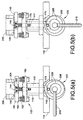
element 112 is used in a first step of cleaning an acoustic ink printhead, such as comprised of a plurality ofejectors 10 previously described. As shown in Figures 5(a)-(c), cappingelement 112 is moved into alignment with printhead array in a manner known within the art. Next, as shown, cappingelement 112 is engaged with printhead such as to form a seal. For the cleaning operation of the present invention, once the dirty printhead is capped, the ink pressure in the printhead is increased significantly to allow ink to escape through the orifices and completely fill asmall reservoir 142 inside the capped structure. It is to be appreciated that increasing ink pressure within the printhead is a known technique and accomplishable by one of skill in the art and understanding of acoustic ink printing. Once the pressure has been increased to move the ink through the orifice structures, the orifices may be allowed to soak for a predetermined time period in order to attempt to dissolve dried ink and loosen dust debris. After a predetermined time period, the vent valve is opened which allows the ink to drain out of the cap through thedrain port 150. While thedrain nozzle 150 is in an open position, the ink pressure inside the printhead is moved to an intermediate high level. This pressure prevents the ink still remaining inside each orifice from reentering the printhead. Following this operation, the outside surface of the orifice plate may be cleaned off by wiping with thewiper blades - Referring now to Figure 6, an alternative embodiment is shown whereby the vent valve is replaced with a dual purpose vent valve and wiper blade. As shown, the valve/
wiper blade 242 is provided to thecapping element 240 within the boundary of the sealingelement 248. It is to be appreciated that when desired, the valve/wiper blade is simply opened or extended toward the printhead so that it engages the surface of the printhead to wipe excess ink therefrom. When wiping is not desired, the valve/wiper blade is retracted to a "valve open" or "valve closed" state depending on the stage of the capping and filling procedure being implemented. - As shown in Figure 7, a
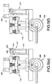
capping element 240 is disposed in abase portion 260 that accommodates other similar capping elements. Further, thewiper blade 242 extends across the full length of the recess of thecapping element 240 within the boundaries of the sealingelement 248. Also shown in Figure 7 isprinthead 300 havingemitter element arrays 302 disposed therein. Of course, these arrays ultimately align with the cappingelements 240 during the capping and filling procedure.
Claims (3)
- A method for filling an acoustic ink printhead with ink at a capping and filling station comprising at least one capping element having a chamber defined therein and a sealing element disposed around a periphery of the reservoir, the method comprising steps of:aligning the printhead with the capping element;moving the sealing element of the capping element into engagement with the printhead such that the sealing element touches the printhead but transmits substantially no force on the printhead;exerting a force on the sealing element to seal the reservoir such that the force is transmitted to the printhead through the sealing element;establishing ink flow in the printhead;removing the force on the capping element to remove the force on the printhead; and,moving the sealing element out of engagement with the printhead.
- The method as set forth in claim 1 wherein exerting the force generates an air cushion within the chamber thereby facilitating establishing the ink flow.
- A capping and filling apparatus useful in connection with printheads employed in acoustic ink printers, the apparatus comprising:a plurality of capping elements, each capping element comprisinga first body portion having a chamber defined therein, a valve disposed in the reservoir and a shoulder portion positioned on a periphery of the reservoir,a sealing element positioned on the shoulder,a second body portion upon which the first body portion is gimbal mounted, anda third body portion comprising a first shaft within a second hollow shaft extending from the second body portion;a base element having a plurality of shaft apertures defined therein and a corresponding plurality of collar elements circumferentially extending from the apertures and sized to receive the third body portions; and,a drive mechanism operatively engaged to the third body portions.
Applications Claiming Priority (2)
| Application Number | Priority Date | Filing Date | Title |
|---|---|---|---|
| US340938 | 1982-01-20 | ||
| US09/340,938 US6595618B1 (en) | 1999-06-28 | 1999-06-28 | Method and apparatus for filling and capping an acoustic ink printhead |
Publications (3)
| Publication Number | Publication Date |
|---|---|
| EP1065060A2 true EP1065060A2 (en) | 2001-01-03 |
| EP1065060A3 EP1065060A3 (en) | 2001-05-02 |
| EP1065060B1 EP1065060B1 (en) | 2008-09-03 |
Family
ID=23335572
Family Applications (1)
| Application Number | Title | Priority Date | Filing Date |
|---|---|---|---|
| EP00113589A Expired - Lifetime EP1065060B1 (en) | 1999-06-28 | 2000-06-27 | A method and apparatus for filling and capping an acoustic ink printhead |
Country Status (4)
| Country | Link |
|---|---|
| US (1) | US6595618B1 (en) |
| EP (1) | EP1065060B1 (en) |
| JP (1) | JP4651158B2 (en) |
| DE (1) | DE60040120D1 (en) |
Cited By (1)
| Publication number | Priority date | Publication date | Assignee | Title |
|---|---|---|---|---|
| EP1386478A1 (en) * | 2002-03-28 | 2004-02-04 | Brother Kogyo Kabushiki Kaisha | Printing device |
Families Citing this family (6)
| Publication number | Priority date | Publication date | Assignee | Title |
|---|---|---|---|---|
| KR100608060B1 (en) * | 2004-07-01 | 2006-08-02 | 삼성전자주식회사 | Inkjet printer |
| US7637588B2 (en) * | 2005-10-11 | 2009-12-29 | Silverbrook Research Pty Ltd | Printhead maintenance assembly comprising maintenance roller and cleaning mechanism |
| EP2114685A1 (en) | 2007-03-02 | 2009-11-11 | Marvell International Ltd. | Device and method for servicing an inkjet print head on a hand held printer |
| JP4311472B2 (en) * | 2007-04-26 | 2009-08-12 | セイコーエプソン株式会社 | Fluid ejecting apparatus and method for controlling the apparatus |
| EP2232572A4 (en) * | 2007-12-07 | 2012-10-17 | Alion Inc | Focused acoustic printing of patterned photovoltaic materials |
| US20100184244A1 (en) * | 2009-01-20 | 2010-07-22 | SunPrint, Inc. | Systems and methods for depositing patterned materials for solar panel production |
Citations (5)
| Publication number | Priority date | Publication date | Assignee | Title |
|---|---|---|---|---|
| US4967207A (en) * | 1989-07-26 | 1990-10-30 | Hewlett-Packard Company | Ink jet printer with self-regulating refilling system |
| EP0541519A2 (en) * | 1988-09-07 | 1993-05-12 | Seiko Epson Corporation | Ink jet printer sealing method and apparatus |
| EP0676289A2 (en) * | 1994-04-08 | 1995-10-11 | Hewlett-Packard Company | Wet-wiping technique for inkjet printhead |
| US5801735A (en) * | 1995-09-05 | 1998-09-01 | Xerox Corporation | Automated system for refilling ink jet cartridges |
| EP0872346A1 (en) * | 1997-04-14 | 1998-10-21 | Brother Kogyo Kabushiki Kaisha | Ink jet recorder |
Family Cites Families (22)
| Publication number | Priority date | Publication date | Assignee | Title |
|---|---|---|---|---|
| JPS609018Y2 (en) * | 1977-12-30 | 1985-04-01 | 東レ株式会社 | Inkjet head drying prevention device |
| US4308547A (en) | 1978-04-13 | 1981-12-29 | Recognition Equipment Incorporated | Liquid drop emitter |
| US4697195A (en) | 1985-09-16 | 1987-09-29 | Xerox Corporation | Nozzleless liquid droplet ejectors |
| US4751530A (en) | 1986-12-19 | 1988-06-14 | Xerox Corporation | Acoustic lens arrays for ink printing |
| US4751534A (en) | 1986-12-19 | 1988-06-14 | Xerox Corporation | Planarized printheads for acoustic printing |
| US5028937A (en) | 1989-05-30 | 1991-07-02 | Xerox Corporation | Perforated membranes for liquid contronlin acoustic ink printing |
| US5027134A (en) | 1989-09-01 | 1991-06-25 | Hewlett-Packard Company | Non-clogging cap and service station for ink-jet printheads |
| US5041849A (en) | 1989-12-26 | 1991-08-20 | Xerox Corporation | Multi-discrete-phase Fresnel acoustic lenses and their application to acoustic ink printing |
| US5471230A (en) * | 1990-02-13 | 1995-11-28 | Canon Kabushiki Kaisha | Capping means and ink jet recording apparatus using the same |
| US5701146A (en) * | 1991-10-18 | 1997-12-23 | Canon Kabushiki Kaisha | Ink head recovery method and apparatus |
| US5644347A (en) | 1992-09-21 | 1997-07-01 | Hewlett-Packard Company | Inkjet printer with variable wiping capabilities for multiple printheads |
| US5638099A (en) * | 1992-09-30 | 1997-06-10 | Hewlett-Packard Company | Removable service station sled for inkjet printer |
| JP3097718B2 (en) * | 1992-11-06 | 2000-10-10 | セイコーエプソン株式会社 | Ink jet recording apparatus and ink supply method |
| JPH06191055A (en) * | 1992-12-25 | 1994-07-12 | Canon Inc | Ink re-filling device of ink jet recording apparatus |
| JPH06320744A (en) | 1993-04-19 | 1994-11-22 | Xerox Corp | Wet wiping maintenance device for full-width ink jet printer |
| US5565113A (en) | 1994-05-18 | 1996-10-15 | Xerox Corporation | Lithographically defined ejection units |
| JP3317020B2 (en) | 1994-05-24 | 2002-08-19 | 富士ゼロックス株式会社 | Ink jet recording device |
| JP2888511B2 (en) | 1995-07-25 | 1999-05-10 | 富士ゼロックス株式会社 | Inkjet head cleaning method and cleaning cartridge therefor |
| JPH0976493A (en) * | 1995-09-12 | 1997-03-25 | Toshiba Corp | Ink jet recording device |
| JP3414605B2 (en) * | 1995-12-25 | 2003-06-09 | セイコーエプソン株式会社 | Ink jet recording apparatus and maintenance method |
| US6010203A (en) * | 1996-07-09 | 2000-01-04 | Brother Kogyo Kabushiki Kaisha | Apparatus for recovering an ink jet head and ink jet recorder including the same |
| DE69716772T2 (en) * | 1996-12-24 | 2003-07-03 | Seiko Epson Corp | Ink jet recording apparatus |
-
1999
- 1999-06-28 US US09/340,938 patent/US6595618B1/en not_active Expired - Lifetime
-
2000
- 2000-06-22 JP JP2000187212A patent/JP4651158B2/en not_active Expired - Fee Related
- 2000-06-27 DE DE60040120T patent/DE60040120D1/en not_active Expired - Lifetime
- 2000-06-27 EP EP00113589A patent/EP1065060B1/en not_active Expired - Lifetime
Patent Citations (5)
| Publication number | Priority date | Publication date | Assignee | Title |
|---|---|---|---|---|
| EP0541519A2 (en) * | 1988-09-07 | 1993-05-12 | Seiko Epson Corporation | Ink jet printer sealing method and apparatus |
| US4967207A (en) * | 1989-07-26 | 1990-10-30 | Hewlett-Packard Company | Ink jet printer with self-regulating refilling system |
| EP0676289A2 (en) * | 1994-04-08 | 1995-10-11 | Hewlett-Packard Company | Wet-wiping technique for inkjet printhead |
| US5801735A (en) * | 1995-09-05 | 1998-09-01 | Xerox Corporation | Automated system for refilling ink jet cartridges |
| EP0872346A1 (en) * | 1997-04-14 | 1998-10-21 | Brother Kogyo Kabushiki Kaisha | Ink jet recorder |
Cited By (3)
| Publication number | Priority date | Publication date | Assignee | Title |
|---|---|---|---|---|
| EP1386478A1 (en) * | 2002-03-28 | 2004-02-04 | Brother Kogyo Kabushiki Kaisha | Printing device |
| EP1386478A4 (en) * | 2002-03-28 | 2005-01-05 | Brother Ind Ltd | Printing device |
| EP1681846A1 (en) * | 2002-03-28 | 2006-07-19 | Brother Kogyo Kabushiki Kaisha | Printing device |
Also Published As
| Publication number | Publication date |
|---|---|
| JP4651158B2 (en) | 2011-03-16 |
| JP2001026114A (en) | 2001-01-30 |
| EP1065060A3 (en) | 2001-05-02 |
| EP1065060B1 (en) | 2008-09-03 |
| US6595618B1 (en) | 2003-07-22 |
| DE60040120D1 (en) | 2008-10-16 |
Similar Documents
| Publication | Publication Date | Title |
|---|---|---|
| KR100408354B1 (en) | Inkjet printhead inspection service method and inkjet printhead inspection service station for repair | |
| US5065170A (en) | Ink jet printer having a staggered array printhead | |
| US7740335B2 (en) | Liquid ejection apparatus and maintenance method of liquid ejection head | |
| US5790146A (en) | Fluid applicator for maintenance of liquid ink printers | |
| KR100799005B1 (en) | Liquid ejection apparatus with liquid wiper device | |
| US6336699B1 (en) | Self-cleaning wet wipe method and apparatus for cleaning orifices in an AIP type printhead | |
| EP3231613B1 (en) | Cleaning device of liquid ejection head and liquid ejection device | |
| JP2011161687A (en) | Cleaning method and fluid jetting apparatus | |
| EP1065060B1 (en) | A method and apparatus for filling and capping an acoustic ink printhead | |
| JPH04284256A (en) | Ink-jet printing device | |
| JPH0985959A (en) | Ink-jet recording apparatus | |
| JP3555347B2 (en) | Ink-jet type image forming apparatus | |
| US9421778B2 (en) | Liquid discharge apparatus | |
| JPWO2010070975A1 (en) | Liquid jet head, liquid jet recording apparatus, and liquid filling method for liquid jet head | |
| US6517187B1 (en) | Method and apparatus for cleaning residual ink from printhead nozzle faces | |
| JP4506390B2 (en) | Liquid ejecting apparatus and liquid sucking apparatus for liquid ejecting head | |
| JP3520463B2 (en) | Ink jet recording device | |
| JP2005231307A (en) | Liquid injection device, liquid suction apparatus for liquid injection head | |
| JP2007076004A (en) | Recovery device for recording head, and inkjet recording apparatus | |
| JP3138655B2 (en) | Cap mechanism of inkjet recording device | |
| JP2005342991A (en) | Liquid jet device and liquid absorption device of liquid jet head | |
| JP3557805B2 (en) | Ink jet type image forming apparatus and ink suction pump used for the same | |
| JP3596587B2 (en) | Ink jet recording device | |
| JP3175610B2 (en) | Ink jet type image forming apparatus and ink suction pump used for the same | |
| JP2002019139A (en) | Ink jet head recovering apparatus |
Legal Events
| Date | Code | Title | Description |
|---|---|---|---|
| PUAI | Public reference made under article 153(3) epc to a published international application that has entered the european phase |
Free format text: ORIGINAL CODE: 0009012 |
|
| AK | Designated contracting states |
Kind code of ref document: A2 Designated state(s): DE FR GB |
|
| AX | Request for extension of the european patent |
Free format text: AL;LT;LV;MK;RO;SI |
|
| PUAL | Search report despatched |
Free format text: ORIGINAL CODE: 0009013 |
|
| AK | Designated contracting states |
Kind code of ref document: A3 Designated state(s): AT BE CH CY DE DK ES FI FR GB GR IE IT LI LU MC NL PT SE |
|
| AX | Request for extension of the european patent |
Free format text: AL;LT;LV;MK;RO;SI |
|
| 17P | Request for examination filed |
Effective date: 20011102 |
|
| AKX | Designation fees paid |
Free format text: DE FR GB |
|
| 17Q | First examination report despatched |
Effective date: 20050207 |
|
| 17Q | First examination report despatched |
Effective date: 20050207 |
|
| GRAP | Despatch of communication of intention to grant a patent |
Free format text: ORIGINAL CODE: EPIDOSNIGR1 |
|
| GRAS | Grant fee paid |
Free format text: ORIGINAL CODE: EPIDOSNIGR3 |
|
| GRAA | (expected) grant |
Free format text: ORIGINAL CODE: 0009210 |
|
| AK | Designated contracting states |
Kind code of ref document: B1 Designated state(s): DE FR GB |
|
| REG | Reference to a national code |
Ref country code: GB Ref legal event code: FG4D |
|
| REF | Corresponds to: |
Ref document number: 60040120 Country of ref document: DE Date of ref document: 20081016 Kind code of ref document: P |
|
| PLBE | No opposition filed within time limit |
Free format text: ORIGINAL CODE: 0009261 |
|
| STAA | Information on the status of an ep patent application or granted ep patent |
Free format text: STATUS: NO OPPOSITION FILED WITHIN TIME LIMIT |
|
| 26N | No opposition filed |
Effective date: 20090604 |
|
| REG | Reference to a national code |
Ref country code: FR Ref legal event code: PLFP Year of fee payment: 17 |
|
| REG | Reference to a national code |
Ref country code: FR Ref legal event code: PLFP Year of fee payment: 18 |
|
| PGFP | Annual fee paid to national office [announced via postgrant information from national office to epo] |
Ref country code: FR Payment date: 20170523 Year of fee payment: 18 Ref country code: GB Payment date: 20170526 Year of fee payment: 18 Ref country code: DE Payment date: 20170522 Year of fee payment: 18 |
|
| REG | Reference to a national code |
Ref country code: DE Ref legal event code: R119 Ref document number: 60040120 Country of ref document: DE |
|
| GBPC | Gb: european patent ceased through non-payment of renewal fee |
Effective date: 20180627 |
|
| PG25 | Lapsed in a contracting state [announced via postgrant information from national office to epo] |
Ref country code: GB Free format text: LAPSE BECAUSE OF NON-PAYMENT OF DUE FEES Effective date: 20180627 Ref country code: FR Free format text: LAPSE BECAUSE OF NON-PAYMENT OF DUE FEES Effective date: 20180630 Ref country code: DE Free format text: LAPSE BECAUSE OF NON-PAYMENT OF DUE FEES Effective date: 20190101 |