EP1065156A1 - Double pressurized container for charging undercup and double pressurized products using the container - Google Patents
Double pressurized container for charging undercup and double pressurized products using the container Download PDFInfo
- Publication number
- EP1065156A1 EP1065156A1 EP98945574A EP98945574A EP1065156A1 EP 1065156 A1 EP1065156 A1 EP 1065156A1 EP 98945574 A EP98945574 A EP 98945574A EP 98945574 A EP98945574 A EP 98945574A EP 1065156 A1 EP1065156 A1 EP 1065156A1
- Authority
- EP
- European Patent Office
- Prior art keywords
- inner bag
- main body
- flange
- container main
- double pressurized
- Prior art date
- Legal status (The legal status is an assumption and is not a legal conclusion. Google has not performed a legal analysis and makes no representation as to the accuracy of the status listed.)
- Granted
Links
Images


Classifications
-
- B—PERFORMING OPERATIONS; TRANSPORTING
- B65—CONVEYING; PACKING; STORING; HANDLING THIN OR FILAMENTARY MATERIAL
- B65D—CONTAINERS FOR STORAGE OR TRANSPORT OF ARTICLES OR MATERIALS, e.g. BAGS, BARRELS, BOTTLES, BOXES, CANS, CARTONS, CRATES, DRUMS, JARS, TANKS, HOPPERS, FORWARDING CONTAINERS; ACCESSORIES, CLOSURES, OR FITTINGS THEREFOR; PACKAGING ELEMENTS; PACKAGES
- B65D83/00—Containers or packages with special means for dispensing contents
- B65D83/14—Containers or packages with special means for dispensing contents for delivery of liquid or semi-liquid contents by internal gaseous pressure, i.e. aerosol containers comprising propellant for a product delivered by a propellant
- B65D83/38—Details of the container body
-
- B—PERFORMING OPERATIONS; TRANSPORTING
- B65—CONVEYING; PACKING; STORING; HANDLING THIN OR FILAMENTARY MATERIAL
- B65D—CONTAINERS FOR STORAGE OR TRANSPORT OF ARTICLES OR MATERIALS, e.g. BAGS, BARRELS, BOTTLES, BOXES, CANS, CARTONS, CRATES, DRUMS, JARS, TANKS, HOPPERS, FORWARDING CONTAINERS; ACCESSORIES, CLOSURES, OR FITTINGS THEREFOR; PACKAGING ELEMENTS; PACKAGES
- B65D83/00—Containers or packages with special means for dispensing contents
- B65D83/14—Containers or packages with special means for dispensing contents for delivery of liquid or semi-liquid contents by internal gaseous pressure, i.e. aerosol containers comprising propellant for a product delivered by a propellant
- B65D83/60—Contents and propellant separated
- B65D83/62—Contents and propellant separated by membrane, bag, or the like
-
- B—PERFORMING OPERATIONS; TRANSPORTING
- B65—CONVEYING; PACKING; STORING; HANDLING THIN OR FILAMENTARY MATERIAL
- B65B—MACHINES, APPARATUS OR DEVICES FOR, OR METHODS OF, PACKAGING ARTICLES OR MATERIALS; UNPACKING
- B65B31/00—Packaging articles or materials under special atmospheric or gaseous conditions; Adding propellants to aerosol containers
- B65B31/003—Adding propellants in fluid form to aerosol containers
Definitions
- the invention relates to a double pressurized container for under-cup charging and a double pressurized product using the same. More specifically, the present invention relates to improvements for facilitating under-cup charging in a double pressurized product which is equipped with a container main body with an opening at its upper end, an attached mounting cup for closing the opening, and an inner bag which has flexibility and which is interposed between the container main body and the mounting cup.
- a double pressurized product as a dispenser or aerosol product, which houses a flexible inner bag in its container main body and also which charges the inner bag with a content, i.e. concentrate to be discharged and also charges such a propellant as a pressurized gas between the inner bag and the container main body.
- the content housed in such a double pressurized product can be directly charged into the inner bag via an ejecting valve or through an opening in the inner bag.
- the propellant on the other hand, is charged by either of two methods of charging it through a charging valve independently disposed at a bottom of the container main body or charged through a gap between a flange portion of a mounting cup and a bead portion of the container main body directly before the ejecting valve is crimped to the opening in the container main body using the mounting cup, which is so-called an under-cup charging method.
- a double pressurized product equipped with a charging valve needs additional machining of its container main body and mounting of an independent charging valve, thus increasing its manufacturing cost. Therefore, an under-cup charging method has been proposed so far.
- This under-cup charging method needs to charge a propellant through a gap between its inner bag and a container main body to be sealed in an air-tight manner finally.
- the inner bag needs various devices such as having vertical ribs for securing a passage for the passage (see, for example, Japanese Patent Application Laid-Open Nos. Sho-56-84270 and Sho-57-104571).
- a propellant since a propellant is charged with a high pressure of 0.3-5.0 Mpa, it may enter the inner bag at a gap between the inner bag (its flange portion) and the mounting cup (its curved flange portion) through between the neck portion of the inner bag and the rising wall of the mounting cup. Also, as mentioned above, the propellant (particularly in the case of a nitrogen gas, which has a lower solubility into the concentrate) is charged with a high pressure, part of the propellant which penetrated into the inner bag through the gap may cause a burst of the inner bag, which is a problem.
- the above-mentioned Japanese Patent Application Laid-Open Nos. Sho-56-84270 and Sho-57-104571 suggest that an adhesive agent or a sealant should be interposed between the inner bag and the mounting cup in order to prevent such penetration.
- Japanese Patent Application Laid-Open No. Hei-9-2551 suggests such a method for manufacturing a double pressurized product that a propellant should be charged between the container main body and the inner bag beforehand and then part of the propellant leaked into the inner bag should be discharged by, for example, vacuum suction and then a content should be charged into the inner bag. With this method, no propellant may enter the inner bag. With this method, moreover, the inner bag, when empty, is engaged with and held at a bead portion of the main body, so that the engagement need not to be heavy, thus making it possible to disengage it easily. Also, Japanese Utility model Publication No. Hei-3-4373, though not relating to under-cup charging, discloses a method of folding back the flange portion of the inner bag 2-ply, to omit a gasket.
- the above-mentioned method of interposing an adhesive agent or a sealant between the inner bag and the mounting cup is difficult to put into practice in the present-day assembly-line mass-production step portions whereby the inner bag and the mounting cup are manufactured independently of each other and then mounted at a charging step portion.
- the method by the above-mentioned Japanese Patent Application Laid-Open No. Hei-9-2551 of under-cup-charging a propellant beforehand and removing part of the propellant entered into the inner bag and then charging the inner bag with a content needs to charge the content against an inner pressure, thus being undesirable because of its double-step portion operations.
- the present invention attempts technologically to minimize as much as possible the penetration of a propellant into an inner bag without changing the conventional under-cup charging method as much as possible.
- a rubber-made ring-shaped gasket 104 for sealing a gap between the curved flange portion and a bead portion 103 of a container main body. Then, as shown in Fig. 19b, after assembly, the gasket 104 is abutted against the bead portion 103 directly in order to provide a secure sealing function, so that an outer diameter of a flange portion 106 of an inner bag 105 is made a little smaller than that of the gasket 104.
- the Inventor has devised the present invention, considering that the above-mentioned problem of penetration of a propellant at the time of under-cup charging can be prevented significantly by enhancing a degree of contact between the inner bag and the mounting cup and also by employing a sealing structure between the mounting-cup and the container main body basically providing no gasket or, even if a gasket is provided, by employing such a sealing structure as not to give rise to the above-mentioned problem.
- a double pressurized container for under-cup charging comprises a container main body equipped with an opening at its upper end, a mounting cup attached for closing the opening, and an inner bag which has flexibility and also which is interposed between the container main body and the mounting cup, wherein the above-mentioned inner bag is equipped with a neck portion which is in close contact with an outer periphery of a rising wall of the mounting cup and also which abuts against that periphery with predetermined fitting strength.
- the above-mentioned container main body is equipped at its opening with a bead portion, which is covered by a curved flange equipped to the mounting cup, and the inner bag, on the other hand, is equipped at its upper end with a flange portion which is engaged with the bead portion, which flange portion is given such defined shape, elasticity, or flexibility that it exhibits a sealing function when it is pushed against an inner surface of the curved flange with a charging pressure at the time of the under-cup charging.
- the double pressurized container for the inner bag has, for example, a lip shape such that it exhibits a sealing function when pushed against the inner surface of the curved flange with a charging pressure at the time of the under-cup charging.
- the above-mentioned inner bag flange portion has defined thickness and elasticity such that it exhibits a sealing function onto the container main body and the inner bag when it is clamped between the curved flange and the bead portion.
- the flange, the container main body bead portion, and/or the mounting-cup curved flange are integrated into a line-sealing structure.
- Such a line-sealing structure can be realized by forming a continuous-annular irregular strip which meshes the inner-bag flange portion at a site where an outer surface of the container main-body bead portion and an inner surface of the mounting-cup curved flange, in which case when the flange portion is clamped between the bead portion and the curved flange, a line sealing structure is formed between the irregular strip and the flange portion.
- the flange portion of the inner bag may have an annular step portion or thick portion, in which case that step portion or thick portion constitutes a line sealing structure when the flange portion is clamped between the bead portion and the curved flange.
- a gasket having a smaller outer periphery than an outer periphery of the inner-bag flange portion may be interposed, if desired, between the inner-bag flange portion and the mounting-cup curved flange.
- the above-mentioned mounting cup comprises a plug inserted into an inner surface of the container main body with the inner bag therebetween and a cup-shaped cover made of a metal sheet which covers the plug and which is crimped at its periphery against the outer periphery of the container main body, wherein the fitting size of the plug and that of the inner bag are such that the inner bag may be fit as being expanded slightly.
- the container main body comprises a cylindrical portion at its upper part and an annular protrusion which protrudes inward at the lower part of the cylindrical portion, wherein the inner bag has another cylindrical portion which is fit to the cylindrical portion of the container main body and also the inner bag is sealed when clamped between the side-wall step portion of the mounting cup and the annular protrusion.
- the double pressurized container equipped with the above-mentioned plug and the mounting cup it has a flange portion which covers the entire container main body and the upper end of the inner bag.
- a gasket is interposed between the plug and the inner bag in order to seal them tightly.
- the inner bag may have a height enough to be supported at its bottom by an inner bottom of the container at the time of under-cup charging.
- a double pressurized product according to the present invention comprises any of the above-mentioned pressurized containers, a concentrate charged in the inner bag of the pressurized container, and a propellant charged in a gap between the inner bag and the container main body.
- a tandem-type double pressurized product according to the present invention features coupling the above-mentioned double pressurized products two at a time.
- the neck portion of the inner bag is in close contact with the outer peripheral surface of the rising wall of the mounting cup and also abuts against that surface, so that air-tightness is improved so as to prevent a propellant from entering the inner bag through the gap at the time of under-cup charging.
- size, elasticity and flexibility of the flange portion of the inner bag are predefined so that a sealing function may be exhibited when the flange portion is pushed against the inner surface of the curved flange with a charging pressure. Therefore, a tip of the flange is not easily lifted up, thus suppressing a propellant from entering through the lifted portion.
- a small amount of the propellant, even if entered, does not give rise to such a pressure as to expand a sealed portion because the neck portion of the inner bag strongly abuts against the outer peripheral surface of the rising wall of the mounting cup. With this, the propellant can be prevented from entering the inner bag.
- the outer periphery of the flange portion of the inner bag has a lip shape so that a sealing function may be exhibited when the outer periphery of the flange portion of the inner bag is pushed against the inner surface of the curved flange with a charging pressure at the time of under-cup charging. Therefore, at the time of under-cup charging, the outer periphery of the flange comes in close contact with the inner surface of the curved flange in order to be pushed against the inner surface of the curved flange more strongly with the increasing charging pressure, thus further suppressing leakage into the inner bag.
- the inner bag flange portion has predefined thickness and elasticity such that a sealing function may be exhibited between the container main body and the inner bag when the flange portion is, after assembly, clamped between the curved flange and the bead portion.
- the inner bag operates in place of a conventional gasket, thus eliminating the necessity of the gasket. This bring about even easier close contact between the inner bag flange portion and the mounting cup curved flange inner surface, thus further improving a sealing function at the time of the under-cup charging. With this, a smaller number of parts are required, thus facilitating assembly.
- the flange portion, the container main body bead portion, and/or the mounting cup curved flange are integrated into a line sealing structure.
- such a line sealing structure is given by forming a continuous annular irregular strip which meshes with the flange portion of the inner bag, at such a site where the outer surface of the container main body bead portion and the inner surface of the mounting cup curved flange correspond to each other.
- the inner bag flange portion is equipped with an annular step portion or a thick portion, so that when the flange is clamped between the bead portion and the curved flange, that step portion or thick portion may be clamped particularly strongly. This provides a line sealing structure with an even higher sealing effect.
- a gasket with a smaller outer periphery than an outer periphery of the inner bag flange portion is interposed between the inner bag flange portion and the mounting cup curved flange.
- the mounting cup comprises a plug inserted into the inner surface of the container main body with the inner bag therebetween and a cup-shaped cover made of a metal sheet which covers the plug and also which has its periphery crimped to the outer periphery of the container main body, in such a configuration that the plug may be fitted, in size, to the inner bag while expanding the inner bag slightly.
- the container main body comprises a cylindrical portion at its top and an annular protrusion at the bottom of the cylindrical portion which protrude inward, in such a configuration that the inner bag has a cylindrical portion fitted to the cylindrical portion of the container main body and also the inner bag is sealed when it is clamped between the mounting cup side step portion and the annular protrusion. Therefore, the inner bag may be sealed sufficiently.
- the above-mentioned plug is equipped with a flange portion which covers the container main body and the upper end of the inner bag. With this, the inner bag and the container main body upper end are sufficiently protected by the flange portion.
- a gasket is interposed between the above-mentioned plug and the container main body upper end. With this, the inside of the container main body is sufficiently sealed from the outside.
- a gasket is interposed between the plug and the inner bag for sealing. With this, the above-mentioned gasket acts to provide a tight sealing function between the plug and the inner bag, thus sufficiently sealing the inside of the inner bag.
- the inner bottom of the container main body supports the inner bag charged with a content at the time of under-cup charging. With this, it is not necessary to hold the inner bag when a propellant is charged and, also, the fitting between the inner bag neck portion and the plug is not shifted by a weight of the content.
- the double pressurized product according to the present invention has the above-mentioned pressurized container charged with a concentrate and a propellant, so that little amount of the propellant enters the inner bag.
- a tandem-type double pressurized product according to the present invention employs the above-mentioned type of the double pressurized product, so that each of the product may exhibit all the above-mentioned functions and effects. Also, it is possible to reserve two kinds of agents separately to eject them at the same time and mix them directly before use.
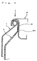
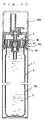
- a double pressurized container A shown in Fig. 1 comprises a container main body 1, an inner bag 2 housed in the container main body 1, and a valve assembly 3 for closing an upper opening in the container main body.
- the container main body 1 having a conventionally known form, is made by forming a metal sheet into a bottomed-cylinder equipped with a barrel portion 4 and a bottom (not shown) and continuously attaching a conical shoulder portion 5 to the upper end of the barrel portion and then providing a bead portion 6 at the cylinder portion upward extending from that upper end by performing outward curling.
- the metal sheet aluminum or tinned steel sheet is used.
- the container main body 1 is shown as formed of one sheet of metal sheet in Fig. 1, as described later, the barrel portion 4 may be wind-formed and, at its upper end, separately formed shoulder portion or dome may be fixed by double-wind-tightening (see Figs. 10-11).
- the above-mentioned inner bag 2 comprises a cylindrical barrel portion 8, a conical shoulder portion 9 continuously extending from an upper end thereof, a cylindrical neck portion 10 upward extending from an upper end thereof, and a flange portion 11 outward expanding an upper end thereof.
- the flange portion 11 extends approximately to an outer periphery of the bead portion 6 in a plane roughly perpendicular to an axis of the neck portion 10. From an upper part of the neck portion 10 to the flange portion 11, a curved portion 12 is disposed in contact with the bead portion 6 of the container main body 1.
- a recess groove 13 is disposed which provides a passage for a propellant at the time of under-cup charging.
- the recess groove 13 is arranged two or more for example in a radial manner.
- the inner bag 2 is formed by performing, for example, blow-molding on synthetic resin with gas-barrier nature.
- the possible materials of the inner bag may include a single-layer or stack-layer sheet made of straight-chain low-density polyethylene (LLDPE), low-density polyethylene (LDTE), high-density polyethylene (HDPE), polypropylene (PP), polyethylene telephtalate (PET), polybutylene telephtalate (PBT), polyethylene naphthalate (PEN), polyacrylonitrile (PAN), ethylene vinyl alcohol copolymer (EVOH), and nylon (NY).
- LLDPE straight-chain low-density polyethylene
- LDTE low-density polyethylene
- HDPE high-density polyethylene
- PP polypropylene
- PET polyethylene telephtalate
- PBT polybutylene telephtalate
- PEN polyethylene naphthalate
- PAN polyacrylonitrile
- EVOH ethylene
- the thickness of the inner bag 2 is 0.1-2.0 mm, preferably 0.3-0.8 mm approximately.
- the inner bag 2 may be made by blow-molding from the above-mentioned single-layer or stack-layer sheet or folding the sheet in a bag and then bonding its circumference. In the latter case, it may also be made from a stack-layer sheet including a metal foil sheet such as an aluminum foil.
- the valve assembly 3 is a known element which comprises a bottomed-cylindrical housing 15, a stem 16 housed movable up and down in the housing, a spring 17 for urging the stem always upward, a mounting cup 18 covering the upper end of the housing 15 and extending to a circumference. At the lower end of the housing 15, an upper end of a dip tube 19 is fitted.
- the dip tube 19 need not always be provided.
- the mounting cup 18 is a known element made of a metal sheet which comprises a housing holding portion 18a for enclosing and holding the upper part of the housing 15, a bottom plate 18b extending outward from around the lower end thereof, a cylindrical rising wall 18c rising from a periphery of the bottom plate, and a curved flange 18d capped onto the bead portion 6 of the container main body 1.
- This embodiment does not employ the conventionally used gasket in the curved flange.
- a conventional pressurized container employs an annular gasket made of elastomeric material such as soft synthetic resin, natural rubber, synthetic rubber such as acrylonitrile butadiene rubber (NBR), stylene butadiene rubber (SBR), butadiene rubber (BR), butyle rubber (IIR), isoprene rubber (IR), chloroprene rubber (CR), ethylene propylene rubber (EPT, EPDM), fluorine rubber, silicone rubber, to seal a gap between the mounting cup curved flange and the bead portion.
- NBR acrylonitrile butadiene rubber
- SBR stylene butadiene rubber
- BR butadiene rubber
- IIR isoprene rubber
- CR chloroprene rubber
- EPT ethylene propylene rubber
- fluorine rubber silicone rubber
- the gasket is omitted, and the inner bag 2 flange portion 11 is provided to seal the gap between the mounting cup 18 and the bead portion 6, and also the flange 11 is provided to extend at its outer periphery close to an outer periphery of the bead portion 6.
- the inner bag 2 is assembled as follows. First, as shown in Fig. 1, the inner bag 2 is inserted into the container main body 1. Since the inner bag 2 has flexibility, it can be inserted into the container main body 1 through a small opening in its upper end. In this state, i.e. with the valve assembly 3 not being disposed at the upper part of the container main body 1, a concentrate to be ejected is charged into the inner bag 2.
- the valve assembly 3 is disposed at the upper part of the container main body 1 and then lowered so that, as shown in Fig. 2, the rising wall 18c of the mounting cup 18 may be inserted into the neck portion 10 of the inner bag 2.
- the outer diameter of the rising wall 18c and the inner diameter of the neck portion 10 are predetermined so as to provide rather tight fitting between them.
- the neck portion 10 of the inner bag 2 is therefore securely fit to the rising wall 18c of the mounting cup 18 with a predetermined fitting strength (loosening strength).
- the inner bag 2 charged with the concentrate is also lifted up together with the valve assembly, since the fitting strength is high. With this, there is given a gap G between the bead portion 6 and the lower end of the outer wall 18e of the curved flange 18d. In this case, however, the bottom of the inner bag 2 is supported by the inner bottom of the container main body, the inner bag need not be lifted up.
- the inner bag 2 flange portion 11 may extend in a plane as indicated by an imaginary line in Fig. 3 or may curve along an inner surface of the curved flange 18d as indicated by a solid line.
- the flange portion 11 When extending in a plane, the flange portion 11, at its outer side, comes in close contact with the inner surface of the outer wall 18e of the curved flange 18d. Though the area from the inner peripheral surface of the bead portion 6 of the container main body 1 through its lower surface abuts against the neck portion 10 and the outer surface of the shoulder portion 11 of the inner bag 2, the gap G becomes in mutual communication with the inside of the container main body 1 through a recess groove 13. With this, a conventionally known charging device is used to charge with a high pressure a propellant via the gap G and the recess groove 13 into a space S between the container main body 1 and the inner bag 2.
- the charging device (not shown) charges the propellant through respective gaps between two ring-shaped members each provided with a seal ring with fitting those two members in a sealing state against the outer surface of the barrel portion 4 of the container main body 1 and the outer surface of the outer wall 18e of the curved flange 18d of the mounting cup 18 respectively to which these two members are fit in a sealing state.
- the flange portion of the inner bag 2 is strongly pressed with the propellant's pressure to the inner surface of the curved flange 18d, thus exhibiting a sealing function. That is, it exhibits the same function as a "lip" of a lip-type seal ring does, thus preventing the propellant from entering the inner bag 2 through the gap between the inner bag 2 and the curved flange 18d. In such a way, the propellant is charged under a high pressure through the recess groove 13 into the space S between the container main body 1 and the inner bag 2.
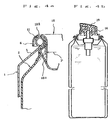
- valve assembly 3 is lowered to securely sandwich, as shown in Fig. 4a, the inner bag 2 flange portion 11 between the curved flange 18d and the bead portion 6, thus exhibiting a sealing function. Then, using claws of a crimping device to push the rising wall 18c of the mounting cup 18 outward partially (see an arrow P), to cause that portion to abut against the inner surface of the shoulder portion 5 of the container main body 1, thus crimping the valve assembly 3 to the container main body 1. Then, as shown in Fig. 4b, a push button 19 is mounted to the stem 16 or, as shown in Fig. 12, a one-touch cap 20 and a cover cap 20a are mounted, to complete assembling of the double pressurized products B and B3.
- the gasket in the curved flange 18d is omitted, to permit the flange portion 11 in the inner bag 2 to seal the gap between the mounting cup 18 and the container main body 1, so that the outer periphery of the flange portion 11 can be extended to the outer periphery of the bead portion 6, thus coming in close contact with the inner surface of the curved flange 18d at the time of under-cup charging.
- the propellant does not enter the inner bag 2 through the gap between the flange portion 11 and the curved flange 18d. Therefore, reaction can be avoided between the concentrate and the propellant, and the inner bag can be prevented from bursting. Also, there is no additional need to release the propellant after under-cup charging and then charge a new propellant.
- the flange portion 11 is clamped with an annular portion with a predetermined width between the upper part inner surface of the curved flange 18d and the top of the bead portion, so that care must be taken sufficiently in, for example, centering between the bead portion 6 and the curved flange 18d.
- the flange portion 11 should preferably be thicker than the other sites, e.g., 0.2-3.0 mm and preferably 0.3-2.0 mm.
- an annular irregular portion i.e. protruding or recessing portion, should preferably be formed on at least one of the curved flange 18d and the bead portion 6, to mesh with the flange portion 11, thus constituting a so-called line-sealing state. In this case, the pressing pressure is high locally, thus further improving the sealing function.
- a continuous annular protrusion strip 21 protruding toward the inner surface (lower side) is formed near the top of the curved flange 18d.
- a continuous annular protrusion strip 22 protruding outward is formed.
- annular protrusion strip 21 As the above-mentioned one is formed near the top of the curved flange 18d, and near the top of the bead portion 6, a continuous annular recess groove (V groove) 23 is formed.
- This annular recess groove 23 can also be formed by performing for example coining machining on a blank material before curl-forming. Then, the annular protrusion strip 21 is combined with the annular recess groove 23 as being fit therein, thus clamping therebetween the flange portion 11 of the inner bag 2. This also meshes with the flange portion 11 securely, thus providing a line sealing structure.
- the annular protrusion strip may be formed on the side of the bead portion 6, and a continuous annular recess groove may be formed on the curved flange 18d side.
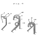
- Figure 6 shows another embodiment for obtaining a line-sealing structure.
- the inner bag 2 is provided at its flange portion 11 with an annular step portion 24, and the flange portion 11 is clamped between the bead portion 6 and the flange 18d.
- annular step portion on the inner bag 2 to be blow-molded, as shown in the leftmost step of Fig. 6, it can be blow-molded into a shape of the step flange 11 and then its ends which provide a periphery of the flange portion 11 can be cut as shown by arrows K and K.
- the inner bag 2 shown in Fig. 7a is formed into such a shape that the flange portion 11 has a moderate S-shaped cross section and the outer peripheral part is curved upward and cut at its upper end.
- this flange portion 11 is inserted into the curved flange 18d as shown in Fig. 7b, the upward curving outer peripheral portion turns downward, coming in close contact with the inner surface of the curved flange 18d. Moreover, it still has upward elastic force always. With this, there is provided strong sealing force between the flange portion 11 and the curved flange 18d, thus preventing a propellant from entering the inner bag through the gap therebetween at the time of under-cup charging.
- the inner bag 2 shown in Figs. 7a and 7b does not employ the thinning recess groove 13 shown in Fig. 1 but instead has an protrusion strip 26 having an upward curving and protruding cross section formed from the neck portion 10 to the shoulder portion 9.
- This protrusion strip 26 is preferably provided two or more in a radial manner.
- Such protrusion strips 26 abut against the inner surface of the shoulder portion of the container main body 1 at the time of under-cup charging, to exhibit such a function as to preserve a passage for the propellant between the protrusion strips 26.
- the protrusion strips 26 may have such a cross-sectional shape as curving and protruding downward.
- the double pressurized container shown in Fig. 8 uses a gasket 27 which has a relatively small width and also which has its outer periphery extending only close to the top of the bead portion 6. The gasket 27 is interposed between the inner bag 2 flange portion 11 and the mounting cup 18 curved flange 18d.
- the gasket 27 may be made of a conventional material.
- the material may an elastomeric material which includes, for example, acrylonitrile butadiene rubber (NBR), stylene butadiene rubber (SBR), butadiene rubber (BR), butyl rubber (IIR), isoprene rubber (IR), chloroprene rubber (CR), ethylene propylene rubber (EPT, EPDM), fluorine rubber, silicone rubber, and other synthetic rubber, natural rubber, soft synthetic resin, and the like.
- NBR acrylonitrile butadiene rubber
- SBR stylene butadiene rubber
- BR butadiene rubber
- IIR isoprene rubber
- CR chloroprene rubber
- EPT ethylene propylene rubber
- fluorine rubber silicone rubber, and other synthetic rubber, natural rubber, soft synthetic resin, and the like.
- the sealing function by means of the inner bag 2 flange portion 11 is not deteriorated at the time of under-cup charging, thus preventing the propellant from entering the inner bag 2.
- the elasticity of the gasket 27 as well as the synergism between the flange portion 11 and the gasket 27 further improve a sealing function between the curved flange 18d and the inner bags 2 and a sealing function between the inner bag 2 and the bead portion 6.
- the sealing force is not deteriorated, thus beneficially maintaining a sealing function for a long time.
- a mounting cup 18 is made of a laminated sheet 28 which comprises a metal sheet 28a and an underlying (inner side of the container) synthetic resin film 28b or sheet which is made of polyethylene, polypropylene, polyethylene telephtalate, ethylene-vinyl alcohol copolymer, and nylon.
- the film can be use not only with single layer but also with laminated layers. To assemble this, therefore, a sealing function between the inner bag 2 and the mounting cup 18 becomes large, further preventing the propellant from entering the inner bag 2. Moreover, the sealing function after the assembly of the pressurized product can be enlarged.
- a synthetic resin film 29 or sheet made of the above-mentioned materials is laminated on the container main body 1, particularly on the inner surface of the bead portion 6 also. Therefore, the sealing function becomes large between the container main body 1 bead portion 6 and the inner bag 2 flange portion 11 as well as between the bead portion 6 and the curved flange 18d, thus surely preventing leakage of the propellant or concentrate even without a gasket.
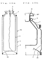
- the above-mentioned pressurized containers all have the shoulder portion 5 integrally formed at the upper end of the barrel portion 4 of the container main body 1, as shown in Figs. 10A and 10B, at the upper end of the barrel portion 4 made of a cylindrical metal sheet such as tinned steel sheet (tin plate) is double-wind-tightened and fixed a dome 7 formed from a tinned steel sheet so that the bead portion 6 disposed at the upper end opening of the dome 7 is covered and mounted with the curved flange 18d of the mounting cup 18.
- the bottom portion 4a is likewise double-wind-tightened and fixed to the lower end of the barrel portion 4, thus overall providing a so-called a three-piece can. Even such a double pressurized container A2 exhibits the same functions and effects as mentioned above at the time of under-cup charging.
- Figure 11 shows a double pressurized product B2 in which the inner bag 2 of the pressurized container shown in Fig. 10 is charged with a concentrate G and a gap space between the inner bag 2 and the container main body 1 is charged with a propellant PR and then a one-touch cap 39 equipped with a spout 38 is mounted.
- the one-touch cap 39 is mounted to the curved flange 18d of the mounting cap 18, it may be mounted to the double-wind-tightened portions 40 of the dome 7 and the barrel portion 4.
- the propellant used may include compressed gas such as nitrogen, carbon dioxide gas, dinitrogen monoxide, compressed air, argon gas, and liquefied gas such as petroleum gas (LPG), dimethyl ether (DEM), fleon gas, etc. and mixtures thereof.
- compressed gas such as nitrogen, carbon dioxide gas, dinitrogen monoxide, compressed air, argon gas, and liquefied gas such as petroleum gas (LPG), dimethyl ether (DEM), fleon gas, etc. and mixtures thereof.
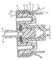
- the double pressurized product B3 shown in Fig. 12 is equipped with the container main body 1 with a relatively small, preferably 15-35-mm diameter, at the upper end of which is provided with no bead portion, instead, an upper portion 31 is cylindrically extending from the shoulder portion 30. As shown in Fig. 13, at the lower part of the cylindrical portion 31 is provided an annular protrusion 32 which protrudes inward.
- the container main body 1 and other components are essentially the same as those of the above-mentioned container main body 1 of the pressurized container A.
- the inner bag 2 is formed from synthetic resin etc. like in the above-mentioned case.
- the inner bag 2 is, as shown in Fig. 13, equipped continuously with a fitting portion (corresponding to the neck portion) 33 which is inscribed with a cylindrical portion 31 of the container main body 1, a portion 33a having a slightly smaller diameter below the fitting portion 33, and a barrel portion 8 having a slightly larger diameter below that portion 33a.
- the fitting portion 33 and the smaller-diameter portion 33a are coupled with an inclined surface 33b engaged with the upper surface of the annular protrusion 32 of the container main body.
- the lower end 34 of the inner bag 2 is, in a normal state, sharp-edged like a cone as shown in Fig.
- the inner bag 2 is charged with the concentrate G, and the space between the container main body 1 and the inner bag 2 is charged with the propellant PR.
- the barrel portion or the opening of the inner bag 2 may partially be formed in bellows. In this case, it can easily be pressed downward and compressed and also restored.
- the mounting cup 18 of the valve assembly 3 comprises a plug 35 fit via the inner bag 2 to the cylindrical portion 31 of the container main body 1 and a cover 36 with which the plug is mounted to the container main body.
- the plug 35 is equipped with a cylindrical peripheral portion 37 at which it is mounted to the container main body 1 and a cylindrical bottomed housing retainer portion 38 which is turned upside-down for holding the housing 15. Both of these are continuous at the lower part 39, between which is formed an annular groove 40 open upward.
- the plug 35 is usually made of polyethylene, polypropylene, nylon, polyacetal, juracon, or other synthetic resin, but may be made of other materials.
- a radial flange portion 41 which is engaged with the upper end of the cylindrical portion 31 of the container main body 1, the lower part of which provides a rising wall 42 which is closely fitted to the fitting portion 33 of the inner bag 2.
- the rising wall 42 has a diameter slightly larger than the inner diameter of the fitting portion 33 of the inner bag 2 in a normal state, thus securing a sufficient sealing nature due to the fitting between them.
- the rising wall 42 has also at its lower part a step 44 which is engaged through the inclined surface 33b of the inner bag 2 with the annular protrusion 32 of the container main body 1. No gasket is interposed between the inner bag 2 and the container main body 1 nor between the container main body and the plug 35 of the mounting cup 3. No gasket is interposed between the plug 35 and the container main body 1 either.
- an engaging protrusion 46 for engagement with a engaging step portion 15a of the upper part of the housing 15.
- the housing 15, the stem 16 so housed therein as to be movable vertically, the spring 17 for urging the stem vertically, and the valve rubber 45 are essentially the same as those with the valve assembly 3 in Fig. 1.
- the cover 36 is a cup-shaped product of a thin metal sheet and its upper bottom surface is covered over the housing retainer portion 38 and the peripheral portion 37.
- the upper bottom surface is also provided with a fitting portion 36a which abuts against the inner surface of the annular groove portion 40.
- the peripheral portion 36b of the cover 36 is fit to the outer surface of the cylindrical portion 31 of the container main body 1 and its roughly lower end is crimped into a groove formed on the side of the outer surface of the annular protrusion 32 of the container main body.
- valve mounting step S2 the valve assembly 3 is mounted at the upper end of the inner bag 2 (valve mounting step S2).
- the inner surface of the fitting portion 33 of the inner bag 2 abuts closely against the rising wall 42 of the plug 35, thus exhibiting a sealing function.
- a propellant charging head 51 is covered around the valve assembly 3 and the container main body 1, to charge through a gap between the mounting cup 18 and the container main body 1 (propellant charging step S3).
- the propellant enters a space S between the inner bag 2 and the container main body 1 through a gap between the cylindrical portion 31 of the container main body and the small-diameter portion 33a of the inner bag.
- the propellant used here may be the above-mentioned compressed gas or liquefied gas.
- the fitting portion 33 of the inner bag 2 strongly abuts against the rising wall 42 of the plug 35 and, also, comes in close contact with it because of the high pressure, the propellant does not enter the inner bag 2 through the gap therebetween.
- valve assembly 3 When charging is completed, the valve assembly 3 is fit to the upper end of the container main body 1 and crimped at the surrounding (valve crimping step S4). In this state, a bottom portion 34 of the inner bag 2 is pressed against the inner bottom surface of the container main body 1 and deformed to some extent. Thus, the valve assembly 3 is mounted to the container main body 1 and the spout fitted one-touch cap 20 and the cover cap 20a are mounted, thereby obtaining a double pressurized product B3 shown in Fig. 12.
- Figure 16 shows a state where in the pressurized product shown in Fig. 13, a ring-shaped gasket 60 is interposed between the upper end of the cylindrical portion 31 of the container main body 1 and the flange 41 of the plug 35 of the mounting cup 3.
- the lower part of the gasket 60 is sandwiched between the rising wall (side wall) 42 of the plug 35 and the inner surface of the container main body 1, thus exhibiting a sealing function.
- the gasket 60 does not abut against the upper end of the cylindrical fitting portion 33 of the inner bag 2.
- the gasket 60 may be made of a conventional material.
- the material may include acrylonitrile butadiene rubber (NBR), stylene butadiene rubber (SBR), butadiene rubber (BR), butyle rubber (IIR), isoprene rubber (IR), chroloprene rubber (CR), ethylene propyrene rubber (EPT, EPDM), fluorine rubber, silicone rubber, and other synthetic rubber, natural rubber, and soft synthetic resin and other elastomers.
- NBR acrylonitrile butadiene rubber
- SBR stylene butadiene rubber
- BR butadiene rubber
- IIR isoprene rubber
- IR chroloprene rubber
- EPT ethylene propyrene rubber
- fluorine rubber silicone rubber, and other synthetic rubber, natural rubber, and soft synthetic resin and other elastomers.
- the gasket 60 is interposed between the plug 35 and the container main body 1, so that after assembly, the inside of the container main body 1 is securely sealed against the outside environment. With this, even if a sealing function is not sufficient between the inner bag 2 and the container main body 1, the gas leaks little.
- the inclined surface 33b of the inner bag 2 is strongly sandwiched between the corner portion of the step portion 44 of the side wall, of the plug 35 and the upper surface of the annular protrusion 32 of the container main body 1. With this, the inside of the inner bag 2 can enjoy a high sealing function for a long period of time. Therefore, there is little risk of the propellant entering the inner bag 2.
- the upper end of the inner bag 2 extends upward so as to securely abut against the above-mentioned gasket 60 after assembly. Therefore, the inside of the inner bag 2 is further securely sealed for a long time.
- the other components are the same as those of the pressurized container shown in Fig. 16.
- Figure 18 shows a two-liquid-mixing type pressurized product B4 using a double pressurized container according to the present invention.
- This product comprises a first pressurized container 55 and a second pressurized container 56 which are the same as the pressurized container of the pressurized product B3 shown in Fig. 12, and a two-liquid-mixing type push button 57 attached to the stems of these containers.
- the inner bag of the first pressurized container 55 is charged with a first agent containing for example oxidation dye
- the inner bag of the second pressurized container 56 is charged with a second agent containing an oxidizer.
- the push button 57 has a first spout 58 in communication with a first aerosol container stem and a second spout 59 in communication with a second pressurized container 56 stem.
- the first spout 58 and the second spout 59 extend parallel to each other and have their own openings adjacent to each other.
- the first agent is ejected from the first pressurized container 55 and the second agent, from the second pressurized container 56 simultaneously. These, therefore, may be appropriately used as a two-concentrate type hair dye.
- the concentrate charged into the inner bag of a double pressurized product according to the present invention is not in particular restricted but may include medicines, quasi-drug ingredients, cosmetics, miscellaneous agents, etc.
- the above-mentioned medicines may include antiphlogistic antalgesia, nasal spray, eye drop, hurt medicine etc.
- the quasi-drug ingredients may include hair dye, oral-refreshment, anti-tragomaschalia, anti-perspirant, hair restoration tonic, permanent-wave agent, bathing agent, medical cosmetics, medical tooth paste, evasive agent, insecticide, etc.
- the cosmetics may include hair cream, hair spray, hair foam, hair tonic, hair dye, and other hair-use cosmetics, after-shave lotion, general cosmetic lotion, eau de Cologne, sunscreen lotion, other cosmetic lotions, cleansing cream, shaving cream, latex, cold cream, hand cream, other creams, baby oil, and other cosmetic oils, packing cosmetics, etc.
- the miscellaneous agents may include industrial products, automobile products, deodorants, glass cleaners, and other domestic products.
- the above-mentioned product pressure is 0.3-1.0 MPa at 20°C when a compressed gas is used as the propellant and at most 0.8 MPa at 35°C when a liquefied gas is used as the propellant.
- the agent type of the above-mentioned products is not limited to the above-mentioned, and a liquid, cream, pate, gel, or foam state can be employed, but may preferably be a cream, pate, or gel state because these highly viscous contents are meritorious for effectuating the properties of the double pressurized container. Also, such material solutions, e.g. hair dye, as those which are liable to corrode metal in contact with themselves.
- the above-mentioned hair dye disclosed in Japanese Patent Application Laid-Open Nos. Hei-8-231345, Hei-8-230959, Hei-7-258045, Hei-8-301740, and Hei-26943 contains aqueous hydrogen peroxide has poor container stability and hates contact with metal, thus being preferably used in a double pressurized container according to the present invention. That is, aqueous hydrogen peroxide itself is very liable to decompose and react with metal to give oxygen, thus sometimes producing an abnormal rise in the inner pressure. To guard against this, as described in the present invention, it should preferably be charged in an inner bag, to which is then applied a pressure of the propellant from the surrounding.
- the above-mentioned tandem-type double pressurized container shown in Fig. 18 may appropriately be used.
- That oxidizing dye consists of dye intermediate products (dye precursors) and couplers providing a variety of color tones given by combinations with the dye intermediate products.
- the dye intermediate is made of para components including, e.g., p-phenylene diamine and p-amino phenol, ortho components including o-phenylene diamine and o-amino phenol, comprising their derivatives.
- the coupler is made of meta-site phenylene diamine, amino phenol, polyhydric phenol, and the like.
- the alkali agent is blended to enhance dying effects and give a light color tone by permitting concurrent proceeding of oxidized decomposition of melanin grains in the hair. Also, it acts to keep the oxidizing dye in an alkali state so as to suppress coloring in storage.
- the alkali agent may include ammonium water, ammonium hydrogen carbonate, and mono-ethanol amine.
- the first agent may be a blend of resorcinol, used as the oxidizing dye, oreic acid and other fat-and-oil phase bases, polyoxyethylene (10) orein alcohol ether and other surfactant, isopropyl alcohol and other solubilizing agents, carboxyvinyl polymer and other thickeners, and purified water for increasing quantity, antioxidants, and the like.
- the pH index of the first agent is typically 8-13 and preferably 9-11 particularly.
- the second agent uses for example aqueous 30% hydrogen peroxide as the oxidant, and a purified water, a stabilizer etc. are mixed therewith.
- the pH index of the second agent is typically 2-5, preferably 2-4.
- the first and second agents should contain a thickener to adjust their viscosity. They may also be foamed. Even with this, the ejected liquid would never drop immediately.
- the container shown in Fig. 13 was prepared two, and each inner bag of these two containers are charged with the first and second agents of the two-liquid hair dye and then charged with a nitrogen gas through a gap between the inner bag and the opening in the container according to a method shown in Fig. 14 and then had the valve crimped.
- the product pressure was 0.7Mpa at 20°C , and by ejecting them, the same amount of contents in a gel state can be ejected.
Abstract
Description
- The invention relates to a double pressurized container for under-cup charging and a double pressurized product using the same. More specifically, the present invention relates to improvements for facilitating under-cup charging in a double pressurized product which is equipped with a container main body with an opening at its upper end, an attached mounting cup for closing the opening, and an inner bag which has flexibility and which is interposed between the container main body and the mounting cup.
- There has been known such a double pressurized product as a dispenser or aerosol product, which houses a flexible inner bag in its container main body and also which charges the inner bag with a content, i.e. concentrate to be discharged and also charges such a propellant as a pressurized gas between the inner bag and the container main body. The content housed in such a double pressurized product can be directly charged into the inner bag via an ejecting valve or through an opening in the inner bag. The propellant, on the other hand, is charged by either of two methods of charging it through a charging valve independently disposed at a bottom of the container main body or charged through a gap between a flange portion of a mounting cup and a bead portion of the container main body directly before the ejecting valve is crimped to the opening in the container main body using the mounting cup, which is so-called an under-cup charging method.
- A double pressurized product equipped with a charging valve needs additional machining of its container main body and mounting of an independent charging valve, thus increasing its manufacturing cost. Therefore, an under-cup charging method has been proposed so far. This under-cup charging method, however, needs to charge a propellant through a gap between its inner bag and a container main body to be sealed in an air-tight manner finally. With this, in particular, in such a type of a double pressurized container that a flange portion of the inner bag is hung at bead portion disposed in an opening in the container main body, the inner bag needs various devices such as having vertical ribs for securing a passage for the passage (see, for example, Japanese Patent Application Laid-Open Nos. Sho-56-84270 and Sho-57-104571).
- Also, since a propellant is charged with a high pressure of 0.3-5.0 Mpa, it may enter the inner bag at a gap between the inner bag (its flange portion) and the mounting cup (its curved flange portion) through between the neck portion of the inner bag and the rising wall of the mounting cup. Also, as mentioned above, the propellant (particularly in the case of a nitrogen gas, which has a lower solubility into the concentrate) is charged with a high pressure, part of the propellant which penetrated into the inner bag through the gap may cause a burst of the inner bag, which is a problem. The above-mentioned Japanese Patent Application Laid-Open Nos. Sho-56-84270 and Sho-57-104571 suggest that an adhesive agent or a sealant should be interposed between the inner bag and the mounting cup in order to prevent such penetration.
- Japanese Patent Application Laid-Open No. Hei-9-2551, on the other hand, suggests such a method for manufacturing a double pressurized product that a propellant should be charged between the container main body and the inner bag beforehand and then part of the propellant leaked into the inner bag should be discharged by, for example, vacuum suction and then a content should be charged into the inner bag. With this method, no propellant may enter the inner bag. With this method, moreover, the inner bag, when empty, is engaged with and held at a bead portion of the main body, so that the engagement need not to be heavy, thus making it possible to disengage it easily. Also, Japanese Utility model Publication No. Hei-3-4373, though not relating to under-cup charging, discloses a method of folding back the flange portion of the inner bag 2-ply, to omit a gasket.
- The above-mentioned method of interposing an adhesive agent or a sealant between the inner bag and the mounting cup is difficult to put into practice in the present-day assembly-line mass-production step portions whereby the inner bag and the mounting cup are manufactured independently of each other and then mounted at a charging step portion. In addition, the method by the above-mentioned Japanese Patent Application Laid-Open No. Hei-9-2551 of under-cup-charging a propellant beforehand and removing part of the propellant entered into the inner bag and then charging the inner bag with a content needs to charge the content against an inner pressure, thus being undesirable because of its double-step portion operations.
- The present invention attempts technologically to minimize as much as possible the penetration of a propellant into an inner bag without changing the conventional under-cup charging method as much as possible.
- It has been found that such penetration of a propellant through a gap can be reduced to some extent by enhancing the strength of sealing between the inner bag and the mounting cup. The inner bag, however, has a flexibility and the flange portion of the inner bag cannot be prevented from being lifted, so that it is impossible to prevent penetration sufficiently. With this, the Inventor has analyzed and discussed about a mechanism of penetration into the inner bag at the time of under-cup charging with a conventional double pressurized product. As a result, the Inventor has found that in the case of a double pressurized container using a container main body having a bead portion, a gasket placed inside the curved flange portion of the mounting cup has a significant function on the penetration of a propellant into the inner bag.
- That is, in such a double pressurized product, as shown in Fig. 19a, in a
curved flange portion 102 of amounting cup 101 is housed a rubber-made ring-shapedgasket 104 for sealing a gap between the curved flange portion and abead portion 103 of a container main body. Then, as shown in Fig. 19b, after assembly, thegasket 104 is abutted against thebead portion 103 directly in order to provide a secure sealing function, so that an outer diameter of aflange portion 106 of aninner bag 105 is made a little smaller than that of thegasket 104. - Therefore, when, during assembly, a valve assembly is once mounted on the upper part of the container main body and then lifted up for under-cup charging, as shown in Fig. 20, the
gasket 104 is in close contact with the curved flange portion therein and, on the other hand, an outer periphery of theflange portion 106 of the inner bag is separate from the surface of thegasket 104 or only a slightly abutted against it. Therefore, it is considered that at the time of under-cup-charging, the outer periphery of theflange portion 106 is lifted up, thus permitting a propellant to enter the inner bag through agap 107. - With this, the Inventor has devised the present invention, considering that the above-mentioned problem of penetration of a propellant at the time of under-cup charging can be prevented significantly by enhancing a degree of contact between the inner bag and the mounting cup and also by employing a sealing structure between the mounting-cup and the container main body basically providing no gasket or, even if a gasket is provided, by employing such a sealing structure as not to give rise to the above-mentioned problem.
- From the viewpoint of the above, a double pressurized container for under-cup charging according to the present invention comprises a container main body equipped with an opening at its upper end, a mounting cup attached for closing the opening, and an inner bag which has flexibility and also which is interposed between the container main body and the mounting cup, wherein the above-mentioned inner bag is equipped with a neck portion which is in close contact with an outer periphery of a rising wall of the mounting cup and also which abuts against that periphery with predetermined fitting strength.
- In a preferred aspect of the above-mentioned double pressurized container, the above-mentioned container main body is equipped at its opening with a bead portion, which is covered by a curved flange equipped to the mounting cup, and the inner bag, on the other hand, is equipped at its upper end with a flange portion which is engaged with the bead portion, which flange portion is given such defined shape, elasticity, or flexibility that it exhibits a sealing function when it is pushed against an inner surface of the curved flange with a charging pressure at the time of the under-cup charging. In another aspect of the above-mentioned double pressurized container for the inner bag, it has, for example, a lip shape such that it exhibits a sealing function when pushed against the inner surface of the curved flange with a charging pressure at the time of the under-cup charging.
- In still another aspect of the double pressurized container, the above-mentioned inner bag flange portion has defined thickness and elasticity such that it exhibits a sealing function onto the container main body and the inner bag when it is clamped between the curved flange and the bead portion. Still another aspect of the double pressurized container, the flange, the container main body bead portion, and/or the mounting-cup curved flange are integrated into a line-sealing structure. Such a line-sealing structure can be realized by forming a continuous-annular irregular strip which meshes the inner-bag flange portion at a site where an outer surface of the container main-body bead portion and an inner surface of the mounting-cup curved flange, in which case when the flange portion is clamped between the bead portion and the curved flange, a line sealing structure is formed between the irregular strip and the flange portion. Also, the flange portion of the inner bag may have an annular step portion or thick portion, in which case that step portion or thick portion constitutes a line sealing structure when the flange portion is clamped between the bead portion and the curved flange.
- Although none of the above-mentioned aspects usually employs a conventional gasket, a gasket having a smaller outer periphery than an outer periphery of the inner-bag flange portion may be interposed, if desired, between the inner-bag flange portion and the mounting-cup curved flange.
- In still another aspect of the double pressurized container according to the present invention, the above-mentioned mounting cup comprises a plug inserted into an inner surface of the container main body with the inner bag therebetween and a cup-shaped cover made of a metal sheet which covers the plug and which is crimped at its periphery against the outer periphery of the container main body, wherein the fitting size of the plug and that of the inner bag are such that the inner bag may be fit as being expanded slightly. In this preferred aspect of the double pressurized container, the container main body comprises a cylindrical portion at its upper part and an annular protrusion which protrudes inward at the lower part of the cylindrical portion, wherein the inner bag has another cylindrical portion which is fit to the cylindrical portion of the container main body and also the inner bag is sealed when clamped between the side-wall step portion of the mounting cup and the annular protrusion. In still another aspect of the double pressurized container equipped with the above-mentioned plug and the mounting cup, it has a flange portion which covers the entire container main body and the upper end of the inner bag. In still another aspect, a gasket is interposed between the plug and the inner bag in order to seal them tightly.
- In any of the above-mentioned double pressurized container, the inner bag may have a height enough to be supported at its bottom by an inner bottom of the container at the time of under-cup charging.
- A double pressurized product according to the present invention comprises any of the above-mentioned pressurized containers, a concentrate charged in the inner bag of the pressurized container, and a propellant charged in a gap between the inner bag and the container main body.
- A tandem-type double pressurized product according to the present invention features coupling the above-mentioned double pressurized products two at a time.
- In the above-mentioned double pressurized container according to the present invention, the neck portion of the inner bag is in close contact with the outer peripheral surface of the rising wall of the mounting cup and also abuts against that surface, so that air-tightness is improved so as to prevent a propellant from entering the inner bag through the gap at the time of under-cup charging.
- In still another aspect of the double pressurized container, size, elasticity and flexibility of the flange portion of the inner bag are predefined so that a sealing function may be exhibited when the flange portion is pushed against the inner surface of the curved flange with a charging pressure. Therefore, a tip of the flange is not easily lifted up, thus suppressing a propellant from entering through the lifted portion. A small amount of the propellant, even if entered, does not give rise to such a pressure as to expand a sealed portion because the neck portion of the inner bag strongly abuts against the outer peripheral surface of the rising wall of the mounting cup. With this, the propellant can be prevented from entering the inner bag.
- In still another aspect of the double pressurized container, the outer periphery of the flange portion of the inner bag has a lip shape so that a sealing function may be exhibited when the outer periphery of the flange portion of the inner bag is pushed against the inner surface of the curved flange with a charging pressure at the time of under-cup charging. Therefore, at the time of under-cup charging, the outer periphery of the flange comes in close contact with the inner surface of the curved flange in order to be pushed against the inner surface of the curved flange more strongly with the increasing charging pressure, thus further suppressing leakage into the inner bag.
- In still another aspect of the double pressurized container, the inner bag flange portion has predefined thickness and elasticity such that a sealing function may be exhibited between the container main body and the inner bag when the flange portion is, after assembly, clamped between the curved flange and the bead portion. With this, the inner bag operates in place of a conventional gasket, thus eliminating the necessity of the gasket. This bring about even easier close contact between the inner bag flange portion and the mounting cup curved flange inner surface, thus further improving a sealing function at the time of the under-cup charging. With this, a smaller number of parts are required, thus facilitating assembly.
- In still another aspect of the double pressurized container, the flange portion, the container main body bead portion, and/or the mounting cup curved flange are integrated into a line sealing structure. With this, after assembly, the force clamping the flange portion upward and downward is concentrated at one position on the line sealing portion, thus improving the sealing function as a pressurized product.
- In still another aspect of the double pressurized container, such a line sealing structure is given by forming a continuous annular irregular strip which meshes with the flange portion of the inner bag, at such a site where the outer surface of the container main body bead portion and the inner surface of the mounting cup curved flange correspond to each other. With this, after assembly, the inner bag flange portion meshes with the bead portion at the irregular strip, thus obtaining a line sealing structure with a higher sealing function at that annular irregular strip. This effectively suppresses gas leakage after assembly.
- In still another aspect of the double pressurized container, the inner bag flange portion is equipped with an annular step portion or a thick portion, so that when the flange is clamped between the bead portion and the curved flange, that step portion or thick portion may be clamped particularly strongly. This provides a line sealing structure with an even higher sealing effect.
- In still another aspect of the double pressurized container, a gasket with a smaller outer periphery than an outer periphery of the inner bag flange portion is interposed between the inner bag flange portion and the mounting cup curved flange. With this, the relevant gasket backs up the flange, to enhance the sealing function after assembly. Moreover, deterioration in elasticity caused by relaxation of the flange portion can be compensated. Therefore, long-term sealing is secured advantageously.
- In still another aspect of the double pressurized container, the mounting cup comprises a plug inserted into the inner surface of the container main body with the inner bag therebetween and a cup-shaped cover made of a metal sheet which covers the plug and also which has its periphery crimped to the outer periphery of the container main body, in such a configuration that the plug may be fitted, in size, to the inner bag while expanding the inner bag slightly. With this, there is given even stronger fitting between the mounting cup plug and the inner bag, thus further preventing a propellant from entering the inner bag at the gap at the time of under-cup charging. In this preferred aspect of the double pressurized container, the container main body comprises a cylindrical portion at its top and an annular protrusion at the bottom of the cylindrical portion which protrude inward, in such a configuration that the inner bag has a cylindrical portion fitted to the cylindrical portion of the container main body and also the inner bag is sealed when it is clamped between the mounting cup side step portion and the annular protrusion. Therefore, the inner bag may be sealed sufficiently.
- In still another preferred aspect, the above-mentioned plug is equipped with a flange portion which covers the container main body and the upper end of the inner bag. With this, the inner bag and the container main body upper end are sufficiently protected by the flange portion. In still another preferred aspect, a gasket is interposed between the above-mentioned plug and the container main body upper end. With this, the inside of the container main body is sufficiently sealed from the outside. In still another preferred aspect, a gasket is interposed between the plug and the inner bag for sealing. With this, the above-mentioned gasket acts to provide a tight sealing function between the plug and the inner bag, thus sufficiently sealing the inside of the inner bag.
- In still another preferred aspect of the double pressurized container according to the present invention, the inner bottom of the container main body supports the inner bag charged with a content at the time of under-cup charging. With this, it is not necessary to hold the inner bag when a propellant is charged and, also, the fitting between the inner bag neck portion and the plug is not shifted by a weight of the content.
- The double pressurized product according to the present invention has the above-mentioned pressurized container charged with a concentrate and a propellant, so that little amount of the propellant enters the inner bag.
- A tandem-type double pressurized product according to the present invention employs the above-mentioned type of the double pressurized product, so that each of the product may exhibit all the above-mentioned functions and effects. Also, it is possible to reserve two kinds of agents separately to eject them at the same time and mix them directly before use.
-
- Figure 1 is a cross-sectional view showing an important part of a pre-assembly double pressurized container according to one embodiment of the present invention;
- Fig. 2 is a cross-sectional view showing the important part in process of assembly;
- Fig. 3 is a cross-sectional view showing the important part at the time of under-cup charging;
- Figs. 4a and 4b are cross-sectional views respectively showing the important part and the entire product after assembly;
- Figs. 5a and 5b are cross-sectional views showing other respective embodiments of the double pressurized container according to the present invention;
- Fig. 6 is a cross-sectional step view showing a procedure for assembling a double pressurized container according to still another embodiment of the present invention;
- Figs. 7a and 7b are cross-sectional views showing the important part of the double pressurized container according to a still another embodiment of the present invention;
- Figs. 8 and 9 are cross-sectional views showing the important part of the double pressurized container according to a still another embodiment of the present invention;
- Fig. 10a is a vertical cross-sectional view showing the double pressurized container according to a still another embodiment and Fig. 10b is an expanded cross-sectional view showing the important part;
- Fig. 11 is a partial cross-sectional side view showing an important part of a pressurized product employing that double pressurized container according to one embodiment of the present invention;
- Fig. 12 is a vertical cross-sectional view showing the double pressurized product according to a still another embodiment of the present invention and Fig. 13 is an expanded cross-sectional view showing the important part thereof;
- Fig. 14 is a flow diagram showing steps for assembling that double pressurized product;
- Fig. 15 is an expanded cross-sectional view showing an important part of that double pressurized product at the time of under-cup charging;
- Fig. 16 is a cross-sectional view showing an important part of the double pressurized product according to a still another embodiment of the present invention;
- Fig. 17 is a cross-sectional view showing an important part of a double pressurized product according to an embodiment of the present invention;
- Fig. 18 is a cross-sectional view showing a part of the tandem-type double pressurized product according to an embodiment of the present invention;
- Fig. 19a is a cross-sectional view showing an important part of an example of a conventional double pressurized container and Fig. 19b is a cross-sectional view showing an important part of that container after assembled; and
- Fig. 20 is a cross-sectional view showing the important part of the double pressurized container of Fig. 19a at the time of under-cup charging.
-
- A double pressurized container A shown in Fig. 1 comprises a container
main body 1, aninner bag 2 housed in the containermain body 1, and avalve assembly 3 for closing an upper opening in the container main body. The containermain body 1, having a conventionally known form, is made by forming a metal sheet into a bottomed-cylinder equipped with abarrel portion 4 and a bottom (not shown) and continuously attaching aconical shoulder portion 5 to the upper end of the barrel portion and then providing abead portion 6 at the cylinder portion upward extending from that upper end by performing outward curling. As the metal sheet, aluminum or tinned steel sheet is used. Although the containermain body 1 is shown as formed of one sheet of metal sheet in Fig. 1, as described later, thebarrel portion 4 may be wind-formed and, at its upper end, separately formed shoulder portion or dome may be fixed by double-wind-tightening (see Figs. 10-11). - The above-mentioned
inner bag 2 comprises acylindrical barrel portion 8, aconical shoulder portion 9 continuously extending from an upper end thereof, acylindrical neck portion 10 upward extending from an upper end thereof, and aflange portion 11 outward expanding an upper end thereof. In this embodiment, theflange portion 11 extends approximately to an outer periphery of thebead portion 6 in a plane roughly perpendicular to an axis of theneck portion 10. From an upper part of theneck portion 10 to theflange portion 11, acurved portion 12 is disposed in contact with thebead portion 6 of the containermain body 1. Also, from a lower half of theneck portion 10 to theshoulder portion 9, arecess groove 13 is disposed which provides a passage for a propellant at the time of under-cup charging. Preferably, therecess groove 13 is arranged two or more for example in a radial manner. - The
inner bag 2 is formed by performing, for example, blow-molding on synthetic resin with gas-barrier nature. The possible materials of the inner bag may include a single-layer or stack-layer sheet made of straight-chain low-density polyethylene (LLDPE), low-density polyethylene (LDTE), high-density polyethylene (HDPE), polypropylene (PP), polyethylene telephtalate (PET), polybutylene telephtalate (PBT), polyethylene naphthalate (PEN), polyacrylonitrile (PAN), ethylene vinyl alcohol copolymer (EVOH), and nylon (NY). For example, a three-layer stack film may be used which is made of three layers of LDPE/EVOH/LDPE. The thickness of theinner bag 2 is 0.1-2.0 mm, preferably 0.3-0.8 mm approximately. Theinner bag 2 may be made by blow-molding from the above-mentioned single-layer or stack-layer sheet or folding the sheet in a bag and then bonding its circumference. In the latter case, it may also be made from a stack-layer sheet including a metal foil sheet such as an aluminum foil. - The
valve assembly 3 is a known element which comprises a bottomed-cylindrical housing 15, astem 16 housed movable up and down in the housing, aspring 17 for urging the stem always upward, a mountingcup 18 covering the upper end of thehousing 15 and extending to a circumference. At the lower end of thehousing 15, an upper end of adip tube 19 is fitted. Thedip tube 19 need not always be provided. The mountingcup 18 is a known element made of a metal sheet which comprises a housing holding portion 18a for enclosing and holding the upper part of thehousing 15, a bottom plate 18b extending outward from around the lower end thereof, a cylindrical rising wall 18c rising from a periphery of the bottom plate, and acurved flange 18d capped onto thebead portion 6 of the containermain body 1. This embodiment, however, does not employ the conventionally used gasket in the curved flange. - That is, a conventional pressurized container, no matter whether it is of a usual type or a double pressurized type, employs an annular gasket made of elastomeric material such as soft synthetic resin, natural rubber, synthetic rubber such as acrylonitrile butadiene rubber (NBR), stylene butadiene rubber (SBR), butadiene rubber (BR), butyle rubber (IIR), isoprene rubber (IR), chloroprene rubber (CR), ethylene propylene rubber (EPT, EPDM), fluorine rubber, silicone rubber, to seal a gap between the mounting cup curved flange and the bead portion. In the double pressurized container, the inner bag flange portion sandwiched between these two portions extends only to the upper end of the bead portion in order not to prevent abutting between the gasket and the bead portion.
- In this embodiment, however, the gasket is omitted, and the
inner bag 2flange portion 11 is provided to seal the gap between the mountingcup 18 and thebead portion 6, and also theflange 11 is provided to extend at its outer periphery close to an outer periphery of thebead portion 6. - Thus configured container
main body 1, theinner bag 2, and thevalve assembly 3 are assembled as follows. First, as shown in Fig. 1, theinner bag 2 is inserted into the containermain body 1. Since theinner bag 2 has flexibility, it can be inserted into the containermain body 1 through a small opening in its upper end. In this state, i.e. with thevalve assembly 3 not being disposed at the upper part of the containermain body 1, a concentrate to be ejected is charged into theinner bag 2. - Next, as shown in Fig. 1 again, the
valve assembly 3 is disposed at the upper part of the containermain body 1 and then lowered so that, as shown in Fig. 2, the rising wall 18c of the mountingcup 18 may be inserted into theneck portion 10 of theinner bag 2. The outer diameter of the rising wall 18c and the inner diameter of theneck portion 10 are predetermined so as to provide rather tight fitting between them. Theneck portion 10 of theinner bag 2 is therefore securely fit to the rising wall 18c of the mountingcup 18 with a predetermined fitting strength (loosening strength). - In this state, when the
valve assembly 3 is lifted up with a gas charging pressure or by use of an auxiliary-use vacuum device, as shown in Fig. 3, theinner bag 2 charged with the concentrate is also lifted up together with the valve assembly, since the fitting strength is high. With this, there is given a gap G between thebead portion 6 and the lower end of the outer wall 18e of thecurved flange 18d. In this case, however, the bottom of theinner bag 2 is supported by the inner bottom of the container main body, the inner bag need not be lifted up. Theinner bag 2flange portion 11 may extend in a plane as indicated by an imaginary line in Fig. 3 or may curve along an inner surface of thecurved flange 18d as indicated by a solid line. When extending in a plane, theflange portion 11, at its outer side, comes in close contact with the inner surface of the outer wall 18e of thecurved flange 18d. Though the area from the inner peripheral surface of thebead portion 6 of the containermain body 1 through its lower surface abuts against theneck portion 10 and the outer surface of theshoulder portion 11 of theinner bag 2, the gap G becomes in mutual communication with the inside of the containermain body 1 through arecess groove 13. With this, a conventionally known charging device is used to charge with a high pressure a propellant via the gap G and therecess groove 13 into a space S between the containermain body 1 and theinner bag 2. Specifically, the charging device (not shown) charges the propellant through respective gaps between two ring-shaped members each provided with a seal ring with fitting those two members in a sealing state against the outer surface of thebarrel portion 4 of the containermain body 1 and the outer surface of the outer wall 18e of thecurved flange 18d of the mountingcup 18 respectively to which these two members are fit in a sealing state. - In this case, the flange portion of the
inner bag 2 is strongly pressed with the propellant's pressure to the inner surface of thecurved flange 18d, thus exhibiting a sealing function. That is, it exhibits the same function as a "lip" of a lip-type seal ring does, thus preventing the propellant from entering theinner bag 2 through the gap between theinner bag 2 and thecurved flange 18d. In such a way, the propellant is charged under a high pressure through therecess groove 13 into the space S between the containermain body 1 and theinner bag 2. - Afterward, like in the case of conventional methods, the
valve assembly 3 is lowered to securely sandwich, as shown in Fig. 4a, theinner bag 2flange portion 11 between thecurved flange 18d and thebead portion 6, thus exhibiting a sealing function. Then, using claws of a crimping device to push the rising wall 18c of the mountingcup 18 outward partially (see an arrow P), to cause that portion to abut against the inner surface of theshoulder portion 5 of the containermain body 1, thus crimping thevalve assembly 3 to the containermain body 1. Then, as shown in Fig. 4b, apush button 19 is mounted to thestem 16 or, as shown in Fig. 12, a one-touch cap 20 and acover cap 20a are mounted, to complete assembling of the double pressurized products B and B3. - As mentioned above, in this double pressurized container A, the gasket in the
curved flange 18d is omitted, to permit theflange portion 11 in theinner bag 2 to seal the gap between the mountingcup 18 and the containermain body 1, so that the outer periphery of theflange portion 11 can be extended to the outer periphery of thebead portion 6, thus coming in close contact with the inner surface of thecurved flange 18d at the time of under-cup charging. With this, the propellant does not enter theinner bag 2 through the gap between theflange portion 11 and thecurved flange 18d. Therefore, reaction can be avoided between the concentrate and the propellant, and the inner bag can be prevented from bursting. Also, there is no additional need to release the propellant after under-cup charging and then charge a new propellant. - As in the case of the above-mentioned double pressurized container A, only by clamping the
inner bag 2flange 11 between the mountingcup 18curved flange 18d and the containermain body 1bead portion 6, a sufficient sealing function can be obtained. In this case, specifically, theflange portion 11 is clamped with an annular portion with a predetermined width between the upper part inner surface of thecurved flange 18d and the top of the bead portion, so that care must be taken sufficiently in, for example, centering between thebead portion 6 and thecurved flange 18d. Also, if the inner bag is made of soft synthetic resin, there is provided a lower elastic deformation degree than with a rubber-made gasket, so that sealing leakage may occur at such a site as having a lower clamping pressure. Therefore, theflange portion 11 should preferably be thicker than the other sites, e.g., 0.2-3.0 mm and preferably 0.3-2.0 mm. As shown in Figs. 5a and 5b, on the other hand, an annular irregular portion, i.e. protruding or recessing portion, should preferably be formed on at least one of thecurved flange 18d and thebead portion 6, to mesh with theflange portion 11, thus constituting a so-called line-sealing state. In this case, the pressing pressure is high locally, thus further improving the sealing function. - On the double pressurized container shown in Fig. 5a, a continuous
annular protrusion strip 21 protruding toward the inner surface (lower side) is formed near the top of thecurved flange 18d. Near the top of thebead portion 6 also, a continuous annular protrusion strip 22 protruding outward is formed. These annular protrusion strips 21 and 22 can both be formed by performing for example coining machining on a blank material before being curl-formed. By using these annular protrusion strips 21 and 22 to cause the flange portion to mesh at both its top and back surfaces, a line-sealing structure can be obtained, thus improving the sealing function. With this, even if relaxation occurs, the sealing function is not lost. - In the double pressurized container shown in Fig. 5b, almost the same
annular protrusion strip 21 as the above-mentioned one is formed near the top of thecurved flange 18d, and near the top of thebead portion 6, a continuous annular recess groove (V groove) 23 is formed. Thisannular recess groove 23 can also be formed by performing for example coining machining on a blank material before curl-forming. Then, theannular protrusion strip 21 is combined with theannular recess groove 23 as being fit therein, thus clamping therebetween theflange portion 11 of theinner bag 2. This also meshes with theflange portion 11 securely, thus providing a line sealing structure. Also, the annular protrusion strip may be formed on the side of thebead portion 6, and a continuous annular recess groove may be formed on thecurved flange 18d side. - Figure 6 shows another embodiment for obtaining a line-sealing structure. In this embodiment, the
inner bag 2 is provided at itsflange portion 11 with anannular step portion 24, and theflange portion 11 is clamped between thebead portion 6 and theflange 18d. With this, there is provided such a state that, as shown in the rightward step in Fig. 6, only the site of theannular step 24 is made thick, to support the pushing pressure of the two parties. This leads to a higher sealing pressure, to improve the sealing function. - To form the annular step portion on the
inner bag 2 to be blow-molded, as shown in the leftmost step of Fig. 6, it can be blow-molded into a shape of thestep flange 11 and then its ends which provide a periphery of theflange portion 11 can be cut as shown by arrows K and K. - The
inner bag 2 shown in Fig. 7a is formed into such a shape that theflange portion 11 has a moderate S-shaped cross section and the outer peripheral part is curved upward and cut at its upper end. When thisflange portion 11 is inserted into thecurved flange 18d as shown in Fig. 7b, the upward curving outer peripheral portion turns downward, coming in close contact with the inner surface of thecurved flange 18d. Moreover, it still has upward elastic force always. With this, there is provided strong sealing force between theflange portion 11 and thecurved flange 18d, thus preventing a propellant from entering the inner bag through the gap therebetween at the time of under-cup charging. - The
inner bag 2 shown in Figs. 7a and 7b, does not employ the thinningrecess groove 13 shown in Fig. 1 but instead has anprotrusion strip 26 having an upward curving and protruding cross section formed from theneck portion 10 to theshoulder portion 9. Thisprotrusion strip 26 is preferably provided two or more in a radial manner. Such protrusion strips 26 abut against the inner surface of the shoulder portion of the containermain body 1 at the time of under-cup charging, to exhibit such a function as to preserve a passage for the propellant between the protrusion strips 26. The protrusion strips 26 may have such a cross-sectional shape as curving and protruding downward. - All the above-mentioned embodiments use the inner bag flange portion to exhibit a sealing function between the bead portion and the curved flange and do not employ a
gasket 104 such as provided to the double pressurized container shown in Fig. 19. The gasket, however, may be employed unless it prevents a sealing function by the inner bag flange portion between the bead portion and the curved flange. The double pressurized container shown in Fig. 8 uses agasket 27 which has a relatively small width and also which has its outer periphery extending only close to the top of thebead portion 6. Thegasket 27 is interposed between theinner bag 2flange portion 11 and the mountingcup 18curved flange 18d. Thegasket 27 may be made of a conventional material. The material may an elastomeric material which includes, for example, acrylonitrile butadiene rubber (NBR), stylene butadiene rubber (SBR), butadiene rubber (BR), butyl rubber (IIR), isoprene rubber (IR), chloroprene rubber (CR), ethylene propylene rubber (EPT, EPDM), fluorine rubber, silicone rubber, and other synthetic rubber, natural rubber, soft synthetic resin, and the like. - When such a
gasket 27 is employed, the sealing function by means of theinner bag 2flange portion 11 is not deteriorated at the time of under-cup charging, thus preventing the propellant from entering theinner bag 2. Moreover, after assembly, the elasticity of thegasket 27 as well as the synergism between theflange portion 11 and thegasket 27 further improve a sealing function between thecurved flange 18d and theinner bags 2 and a sealing function between theinner bag 2 and thebead portion 6. Moreover, if relaxation may occur at theinner bag 2flange portion 11, the sealing force is not deteriorated, thus beneficially maintaining a sealing function for a long time. - In the pressurized container shown in Fig. 9, a mounting
cup 18 is made of alaminated sheet 28 which comprises ametal sheet 28a and an underlying (inner side of the container)synthetic resin film 28b or sheet which is made of polyethylene, polypropylene, polyethylene telephtalate, ethylene-vinyl alcohol copolymer, and nylon. The film can be use not only with single layer but also with laminated layers. To assemble this, therefore, a sealing function between theinner bag 2 and the mountingcup 18 becomes large, further preventing the propellant from entering theinner bag 2. Moreover, the sealing function after the assembly of the pressurized product can be enlarged. In the pressurized container shown in Fig. 9, on the containermain body 1, particularly on the inner surface of thebead portion 6 also, asynthetic resin film 29 or sheet made of the above-mentioned materials is laminated. Therefore, the sealing function becomes large between the containermain body 1bead portion 6 and theinner bag 2flange portion 11 as well as between thebead portion 6 and thecurved flange 18d, thus surely preventing leakage of the propellant or concentrate even without a gasket. - Although the above-mentioned pressurized containers all have the
shoulder portion 5 integrally formed at the upper end of thebarrel portion 4 of the containermain body 1, as shown in Figs. 10A and 10B, at the upper end of thebarrel portion 4 made of a cylindrical metal sheet such as tinned steel sheet (tin plate) is double-wind-tightened and fixed adome 7 formed from a tinned steel sheet so that thebead portion 6 disposed at the upper end opening of thedome 7 is covered and mounted with thecurved flange 18d of the mountingcup 18. In this pressurized container A2, thebottom portion 4a is likewise double-wind-tightened and fixed to the lower end of thebarrel portion 4, thus overall providing a so-called a three-piece can. Even such a double pressurized container A2 exhibits the same functions and effects as mentioned above at the time of under-cup charging. - Figure 11 shows a double pressurized product B2 in which the
inner bag 2 of the pressurized container shown in Fig. 10 is charged with a concentrate G and a gap space between theinner bag 2 and the containermain body 1 is charged with a propellant PR and then a one-touch cap 39 equipped with aspout 38 is mounted. Although, in this embodiment, the one-touch cap 39 is mounted to thecurved flange 18d of the mountingcap 18, it may be mounted to the double-wind-tightenedportions 40 of thedome 7 and thebarrel portion 4. - The propellant used may include compressed gas such as nitrogen, carbon dioxide gas, dinitrogen monoxide, compressed air, argon gas, and liquefied gas such as petroleum gas (LPG), dimethyl ether (DEM), fleon gas, etc. and mixtures thereof.
- The double pressurized product B3 shown in Fig. 12 is equipped with the container
main body 1 with a relatively small, preferably 15-35-mm diameter, at the upper end of which is provided with no bead portion, instead, anupper portion 31 is cylindrically extending from theshoulder portion 30. As shown in Fig. 13, at the lower part of thecylindrical portion 31 is provided anannular protrusion 32 which protrudes inward. The containermain body 1 and other components are essentially the same as those of the above-mentioned containermain body 1 of the pressurized container A. - The
inner bag 2 is formed from synthetic resin etc. like in the above-mentioned case. Theinner bag 2 is, as shown in Fig. 13, equipped continuously with a fitting portion (corresponding to the neck portion) 33 which is inscribed with acylindrical portion 31 of the containermain body 1, aportion 33a having a slightly smaller diameter below thefitting portion 33, and abarrel portion 8 having a slightly larger diameter below thatportion 33a. Thefitting portion 33 and the smaller-diameter portion 33a are coupled with aninclined surface 33b engaged with the upper surface of theannular protrusion 32 of the container main body. Thelower end 34 of theinner bag 2 is, in a normal state, sharp-edged like a cone as shown in Fig. 14 and, in an assembled state, is supported as pushed against the inner bottom surface of the containermain body 1. With this also, theinner bag 2 is charged with the concentrate G, and the space between the containermain body 1 and theinner bag 2 is charged with the propellant PR. The barrel portion or the opening of theinner bag 2 may partially be formed in bellows. In this case, it can easily be pressed downward and compressed and also restored. - In this embodiment, as shown in Fig. 13, the mounting
cup 18 of thevalve assembly 3 comprises aplug 35 fit via theinner bag 2 to thecylindrical portion 31 of the containermain body 1 and acover 36 with which the plug is mounted to the container main body. Theplug 35 is equipped with a cylindricalperipheral portion 37 at which it is mounted to the containermain body 1 and a cylindrical bottomedhousing retainer portion 38 which is turned upside-down for holding thehousing 15. Both of these are continuous at thelower part 39, between which is formed anannular groove 40 open upward. Theplug 35 is usually made of polyethylene, polypropylene, nylon, polyacetal, juracon, or other synthetic resin, but may be made of other materials. - At the upper end of the
peripheral portion 37 is disposed outward aradial flange portion 41 which is engaged with the upper end of thecylindrical portion 31 of the containermain body 1, the lower part of which provides a risingwall 42 which is closely fitted to thefitting portion 33 of theinner bag 2. The risingwall 42 has a diameter slightly larger than the inner diameter of thefitting portion 33 of theinner bag 2 in a normal state, thus securing a sufficient sealing nature due to the fitting between them. The risingwall 42 has also at its lower part astep 44 which is engaged through theinclined surface 33b of theinner bag 2 with theannular protrusion 32 of the containermain body 1. No gasket is interposed between theinner bag 2 and the containermain body 1 nor between the container main body and theplug 35 of the mountingcup 3. No gasket is interposed between theplug 35 and the containermain body 1 either. - On the inner surface of the
housing retainer portion 38 is disposed an engagingprotrusion 46 for engagement with a engagingstep portion 15a of the upper part of thehousing 15. Thehousing 15, thestem 16 so housed therein as to be movable vertically, thespring 17 for urging the stem vertically, and thevalve rubber 45 are essentially the same as those with thevalve assembly 3 in Fig. 1. - The
cover 36 is a cup-shaped product of a thin metal sheet and its upper bottom surface is covered over thehousing retainer portion 38 and theperipheral portion 37. The upper bottom surface is also provided with afitting portion 36a which abuts against the inner surface of theannular groove portion 40. Theperipheral portion 36b of thecover 36 is fit to the outer surface of thecylindrical portion 31 of the containermain body 1 and its roughly lower end is crimped into a groove formed on the side of the outer surface of theannular protrusion 32 of the container main body. - Next, a procedure for charging this double pressurized product B3 with a content is described with reference to Fig. 14. First, at the leftmost concentrate charging step S1 in Fig. 14, the
inner bag 2 is put into the containermain body 1. In this state, thelower end 34 of theinner bag 2 abuts against the inner bottom surface of the container main body. In this state also, a concentrate is charged through aconcentrate charging nozzle 50. - Next, the
valve assembly 3 is mounted at the upper end of the inner bag 2 (valve mounting step S2). In this state, as mentioned above, the inner surface of thefitting portion 33 of theinner bag 2 abuts closely against the risingwall 42 of theplug 35, thus exhibiting a sealing function. Then, apropellant charging head 51 is covered around thevalve assembly 3 and the containermain body 1, to charge through a gap between the mountingcup 18 and the container main body 1 (propellant charging step S3). In this state, as shown by an arrow Q in Fig. 15, the propellant enters a space S between theinner bag 2 and the containermain body 1 through a gap between thecylindrical portion 31 of the container main body and the small-diameter portion 33a of the inner bag. The propellant used here may be the above-mentioned compressed gas or liquefied gas. - Although the propellant is compressed with a high pressure, the
fitting portion 33 of theinner bag 2 strongly abuts against the risingwall 42 of theplug 35 and, also, comes in close contact with it because of the high pressure, the propellant does not enter theinner bag 2 through the gap therebetween. - When charging is completed, the
valve assembly 3 is fit to the upper end of the containermain body 1 and crimped at the surrounding (valve crimping step S4). In this state, abottom portion 34 of theinner bag 2 is pressed against the inner bottom surface of the containermain body 1 and deformed to some extent. Thus, thevalve assembly 3 is mounted to the containermain body 1 and the spout fitted one-touch cap 20 and thecover cap 20a are mounted, thereby obtaining a double pressurized product B3 shown in Fig. 12. - Figure 16 shows a state where in the pressurized product shown in Fig. 13, a ring-shaped
gasket 60 is interposed between the upper end of thecylindrical portion 31 of the containermain body 1 and theflange 41 of theplug 35 of the mountingcup 3. The lower part of thegasket 60 is sandwiched between the rising wall (side wall) 42 of theplug 35 and the inner surface of the containermain body 1, thus exhibiting a sealing function. In this embodiment, thegasket 60 does not abut against the upper end of the cylindricalfitting portion 33 of theinner bag 2. Thegasket 60 may be made of a conventional material. The material may include acrylonitrile butadiene rubber (NBR), stylene butadiene rubber (SBR), butadiene rubber (BR), butyle rubber (IIR), isoprene rubber (IR), chroloprene rubber (CR), ethylene propyrene rubber (EPT, EPDM), fluorine rubber, silicone rubber, and other synthetic rubber, natural rubber, and soft synthetic resin and other elastomers. - In this embodiment, the
gasket 60 is interposed between theplug 35 and the containermain body 1, so that after assembly, the inside of the containermain body 1 is securely sealed against the outside environment. With this, even if a sealing function is not sufficient between theinner bag 2 and the containermain body 1, the gas leaks little. Note here that theinclined surface 33b of theinner bag 2 is strongly sandwiched between the corner portion of thestep portion 44 of the side wall, of theplug 35 and the upper surface of theannular protrusion 32 of the containermain body 1. With this, the inside of theinner bag 2 can enjoy a high sealing function for a long period of time. Therefore, there is little risk of the propellant entering theinner bag 2. - In a pressurized product shown in Fig. 17, the upper end of the
inner bag 2 extends upward so as to securely abut against the above-mentionedgasket 60 after assembly. Therefore, the inside of theinner bag 2 is further securely sealed for a long time. The other components are the same as those of the pressurized container shown in Fig. 16. - Figure 18 shows a two-liquid-mixing type pressurized product B4 using a double pressurized container according to the present invention. This product comprises a first
pressurized container 55 and a secondpressurized container 56 which are the same as the pressurized container of the pressurized product B3 shown in Fig. 12, and a two-liquid-mixingtype push button 57 attached to the stems of these containers. The inner bag of the firstpressurized container 55 is charged with a first agent containing for example oxidation dye, and the inner bag of the secondpressurized container 56 is charged with a second agent containing an oxidizer. Thepush button 57 has afirst spout 58 in communication with a first aerosol container stem and asecond spout 59 in communication with a secondpressurized container 56 stem. Thefirst spout 58 and thesecond spout 59 extend parallel to each other and have their own openings adjacent to each other. - When this
push button 57 of the pressurized product B4 is pressed, the first agent is ejected from the firstpressurized container 55 and the second agent, from the secondpressurized container 56 simultaneously. These, therefore, may be appropriately used as a two-concentrate type hair dye. - The concentrate charged into the inner bag of a double pressurized product according to the present invention is not in particular restricted but may include medicines, quasi-drug ingredients, cosmetics, miscellaneous agents, etc. The above-mentioned medicines may include antiphlogistic antalgesia, nasal spray, eye drop, hurt medicine etc.; and the quasi-drug ingredients may include hair dye, oral-refreshment, anti-tragomaschalia, anti-perspirant, hair restoration tonic, permanent-wave agent, bathing agent, medical cosmetics, medical tooth paste, evasive agent, insecticide, etc. The cosmetics may include hair cream, hair spray, hair foam, hair tonic, hair dye, and other hair-use cosmetics, after-shave lotion, general cosmetic lotion, eau de Cologne, sunscreen lotion, other cosmetic lotions, cleansing cream, shaving cream, latex, cold cream, hand cream, other creams, baby oil, and other cosmetic oils, packing cosmetics, etc. The miscellaneous agents may include industrial products, automobile products, deodorants, glass cleaners, and other domestic products.
- Preferably, the above-mentioned product pressure is 0.3-1.0 MPa at 20°C when a compressed gas is used as the propellant and at most 0.8 MPa at 35°C when a liquefied gas is used as the propellant.
- The agent type of the above-mentioned products is not limited to the above-mentioned, and a liquid, cream, pate, gel, or foam state can be employed, but may preferably be a cream, pate, or gel state because these highly viscous contents are meritorious for effectuating the properties of the double pressurized container. Also, such material solutions, e.g. hair dye, as those which are liable to corrode metal in contact with themselves.
- The above-mentioned hair dye disclosed in Japanese Patent Application Laid-Open Nos. Hei-8-231345, Hei-8-230959, Hei-7-258045, Hei-8-301740, and Hei-26943 contains aqueous hydrogen peroxide has poor container stability and hates contact with metal, thus being preferably used in a double pressurized container according to the present invention. That is, aqueous hydrogen peroxide itself is very liable to decompose and react with metal to give oxygen, thus sometimes producing an abnormal rise in the inner pressure. To guard against this, as described in the present invention, it should preferably be charged in an inner bag, to which is then applied a pressure of the propellant from the surrounding.
- Particularly as for a two-liquid-reactive hair dye, the above-mentioned tandem-type double pressurized container shown in Fig. 18 may appropriately be used.
- As the first agent, for example, a blend of an oxidizing dye, alkali agent, surfuctant, etc. is used, and as the second agent, an agent containing an oxidizer for oxidizing that oxidizing dye is used. That oxidizing dye consists of dye intermediate products (dye precursors) and couplers providing a variety of color tones given by combinations with the dye intermediate products. The dye intermediate is made of para components including, e.g., p-phenylene diamine and p-amino phenol, ortho components including o-phenylene diamine and o-amino phenol, comprising their derivatives. The coupler is made of meta-site phenylene diamine, amino phenol, polyhydric phenol, and the like.
- The alkali agent is blended to enhance dying effects and give a light color tone by permitting concurrent proceeding of oxidized decomposition of melanin grains in the hair. Also, it acts to keep the oxidizing dye in an alkali state so as to suppress coloring in storage. The alkali agent may include ammonium water, ammonium hydrogen carbonate, and mono-ethanol amine. Besides the above-mentioned ones, the first agent may be a blend of resorcinol, used as the oxidizing dye, oreic acid and other fat-and-oil phase bases, polyoxyethylene (10) orein alcohol ether and other surfactant, isopropyl alcohol and other solubilizing agents, carboxyvinyl polymer and other thickeners, and purified water for increasing quantity, antioxidants, and the like. The pH index of the first agent is typically 8-13 and preferably 9-11 particularly.
- The second agent, on the other hand, uses for example aqueous 30% hydrogen peroxide as the oxidant, and a purified water, a stabilizer etc. are mixed therewith. The pH index of the second agent is typically 2-5, preferably 2-4. Also, preferably, the first and second agents should contain a thickener to adjust their viscosity. They may also be foamed. Even with this, the ejected liquid would never drop immediately.
- The container shown in Fig. 13 was prepared two, and each inner bag of these two containers are charged with the first and second agents of the two-liquid hair dye and then charged with a nitrogen gas through a gap between the inner bag and the opening in the container according to a method shown in Fig. 14 and then had the valve crimped. The product pressure was 0.7Mpa at 20°C , and by ejecting them, the same amount of contents in a gel state can be ejected.
Claims (16)
- A double pressurized container for under-cup charging comprising a container main body having an opening at an upper end, a mounting cup so mounted as to close said opening, and a flexible inner bag interposed between said container main body and said mounting cup, wherein said inner bag has a neck portion which abuts closely against an outer peripheral surface of a rising wall of said mounting cup with predetermined fitting strength.
- The double pressurized container according to claim 1, wherein said container main body is provided with a bead portion at said opening; said mounting cup is equipped with a curved flange to cover said bead portion; the inner bag is provided at an upper end with a flange portion which engages with said bead portion; said flange portion has such a shape and elasticity or flexibility as to exhibit a sealing function when pressed against an inner surface of said curved flange with a fitting pressure at time of under-cup charging.
- The double pressurized container according to claim 2, wherein an outer periphery of said flange portion of said inner bag is such a shape as to exhibit a sealing function when pressed against an inner surface of said curved flange with a fitting pressure at time of under-cup charging.
- The double pressurized container according to claim 2, wherein said flange portion of said inner bag has such predetermined thickness and elasticity as to exhibit a sealing function onto said container main body and said inner bag when said flange portion is clamped between said curved flange and said bead portion.
- The double pressurized container according to claim 4, wherein said flange portion, said bead portion of said container main body, and/or said curved flange of said mounting cup are configured to constitute a line-sealing structure after assembly.
- The double pressurized container according to claim 5, wherein at a site where an outer surface of said bead portion of said container main body and an inner surface of said curved flange of said mounting cup correspond to each other, a continuous annular irregular strip is formed which meshes with said flange portion of said inner bag, so that when said flange portion is clamped between said bead portion and said curved flange, a line-sealing structure is formed between said irregular strip and said flange portion.
- The double pressurized container according to claim 5, wherein said flange portion of said inner bag is provided with an annular step portion and thick portion, so that when said flange is clamped between said bead portion and said curved flange, said step or thick portion may constitute a line-sealing structure.
- The double pressurized container according to claim 2, 3, 4, 5, 6, or 7, wherein between said flange portion of said inner bag and said curved flange of said mounting cup, a gasket is interposed which has an outer periphery smaller than an outer periphery of said flange portion.
- The double pressurized container according to claim 1, wherein said mounting cup is equipped with a plug inserted into an inner surface of said container main body with an inner bag therebetween and a cup-shaped cover made of a metal sheet which covers said plug and also a periphery of which is crimped to an outer periphery of said container main body; and a size of fitting said plug to said inner bag is such that said inner bag is slightly expanded when said plug is fitted thereto.
- The double pressurized container according to claim 9, wherein said container main body is equipped with a cylindrical portion at an upper part and an annular protrusion which protrudes toward an inner side of said cylindrical portion, said inner bag has a cylindrical portion which is fit to said cylindrical portion of said container main body, and said inner bag is sealed, being clamped between said side step portion and said annular protrusion of said mounting cup.
- The double pressurized container according to claim 9, wherein said plug is equipped with a flange portion which covers said container main body and an upper end of said inner bag.
- The double pressurized container according to claim 9, wherein a gasket is interposed between said plug and said upper part of said container main body in order to seal tightly.
- The double pressurized container according to claim 9, wherein a gasket is interposed between said plug and said inner bag in order to seal tightly.
- The double pressurized container according to any one of the preceding claims, wherein said inner bag has a height such that a bottom of said inner bag may be supported by an inner bottom surface of said container at time of under-cup charging.
- A double pressurized product comprising the double pressurized container according to any one of the preceding claims, a concentrate charged in said inner bag, and a propellant charged in a gap between said inner bag and said container main body.
- A double pressurized product which couples two pieces of the double pressurized product according to claim 15.
Priority Applications (1)
| Application Number | Priority Date | Filing Date | Title |
|---|---|---|---|
| EP11181216A EP2524877A1 (en) | 1997-10-01 | 1998-10-01 | Double pressurized container for charging undercup and double pressurized products using the container |
Applications Claiming Priority (3)
| Application Number | Priority Date | Filing Date | Title |
|---|---|---|---|
| JP28598797 | 1997-10-01 | ||
| JP28598797 | 1997-10-01 | ||
| PCT/JP1998/004446 WO1999016684A1 (en) | 1997-10-01 | 1998-10-01 | Double pressurized container for charging undercup and double pressurized products using the container |
Related Child Applications (1)
| Application Number | Title | Priority Date | Filing Date |
|---|---|---|---|
| EP11181216A Division-Into EP2524877A1 (en) | 1997-10-01 | 1998-10-01 | Double pressurized container for charging undercup and double pressurized products using the container |
Publications (3)
| Publication Number | Publication Date |
|---|---|
| EP1065156A1 true EP1065156A1 (en) | 2001-01-03 |
| EP1065156A4 EP1065156A4 (en) | 2008-07-16 |
| EP1065156B1 EP1065156B1 (en) | 2015-03-25 |
Family
ID=17698555
Family Applications (2)
| Application Number | Title | Priority Date | Filing Date |
|---|---|---|---|
| EP11181216A Withdrawn EP2524877A1 (en) | 1997-10-01 | 1998-10-01 | Double pressurized container for charging undercup and double pressurized products using the container |
| EP98945574.6A Expired - Lifetime EP1065156B1 (en) | 1997-10-01 | 1998-10-01 | Double pressurized container for charging undercup and double pressurized products using the container |
Family Applications Before (1)
| Application Number | Title | Priority Date | Filing Date |
|---|---|---|---|
| EP11181216A Withdrawn EP2524877A1 (en) | 1997-10-01 | 1998-10-01 | Double pressurized container for charging undercup and double pressurized products using the container |
Country Status (6)
| Country | Link |
|---|---|
| US (2) | US6401979B1 (en) |
| EP (2) | EP2524877A1 (en) |
| JP (1) | JP4194752B2 (en) |
| CN (2) | CN1255309C (en) |
| AU (1) | AU751330B2 (en) |
| WO (1) | WO1999016684A1 (en) |
Cited By (7)
| Publication number | Priority date | Publication date | Assignee | Title |
|---|---|---|---|---|
| WO2002056949A1 (en) * | 2001-01-17 | 2002-07-25 | 3M Innovative Properties Company | Medicinal aerosols |
| FR2825351A1 (en) * | 2001-05-31 | 2002-12-06 | Hilti Ag | DEVICE FOR THE STORAGE AND CONTROLLED DELIVERY OF A PRESSURIZED PRODUCT |
| EP1876113A3 (en) * | 2006-07-05 | 2008-07-02 | Ewald Euscher GmbH & Co. KG | Valve disc for a spray can |
| WO2008089875A1 (en) * | 2007-01-23 | 2008-07-31 | Unilever Plc | Small aerosol products |
| EP2739550A2 (en) * | 2011-08-02 | 2014-06-11 | Crown Packaging Technology, Inc. | Aerosol can |
| US9475636B2 (en) | 2010-12-22 | 2016-10-25 | Daizo Corporation | Valve assembly and aerosol container equipped with the same, and aerosol product and process for production thereof |
| WO2017194887A1 (en) | 2016-05-13 | 2017-11-16 | Aptar France Sas | Ring for fluid product dispensing device |
Families Citing this family (44)
| Publication number | Priority date | Publication date | Assignee | Title |
|---|---|---|---|---|
| AU751330B2 (en) * | 1997-10-01 | 2002-08-15 | Daizo Co., Ltd. | Double pressurized container for charging undercup and double pressurized products using the container |
| FR2804665B1 (en) | 2000-02-07 | 2002-06-14 | Oreal | POCKET AEROSOL WITH IMPROVED SEALING |
| JP2001286794A (en) * | 2000-04-05 | 2001-10-16 | Toichi Kojima | Chemiluminescent liquid-containing aerosol product |
| AU2003256255A1 (en) * | 2002-05-21 | 2003-12-12 | Seaquist Perfect Dispensing Foreign, Inc. | Aerosol dispenser for mixing and dispensing multiple fluid products |
| US7357158B2 (en) * | 2002-05-21 | 2008-04-15 | Seaquist Perfect Dispensing Foreign | Aerosol dispenser for mixing and dispensing multiple fluid products |
| GB2391862C (en) * | 2002-08-13 | 2007-01-11 | Shield Medicare Ltd | Spray dispenser assembly and vessel therefor |
| US20080220107A1 (en) * | 2002-09-03 | 2008-09-11 | Pharmacure Health Care Ab | Nasal spray apparatus |
| US7967220B2 (en) * | 2002-09-13 | 2011-06-28 | Bissell Homecare, Inc. | Manual sprayer with dual bag-on-valve assembly |
| US7906473B2 (en) | 2002-09-13 | 2011-03-15 | Bissell Homecare, Inc. | Manual spray cleaner |
| DE50303569D1 (en) * | 2003-04-28 | 2006-07-06 | Coster Tecnologie Speciali Spa | Assembly consisting of dispensing valve and a fluid-tight connected with this bag |
| US7575133B2 (en) * | 2003-10-06 | 2009-08-18 | Crown Cork & Seal Technologies Corporation | Bi-can having internal bag |
| EP1848541A4 (en) | 2005-02-07 | 2013-01-16 | Pharmalight Inc | Method and device for ophthalmic administration of active pharmaceutical ingredients |
| ATE401259T1 (en) * | 2005-02-15 | 2008-08-15 | Goemar Lab Sa | DEVICE FOR DISPENSING FLUIDS, PARTICULARLY MEDICINAL FLUIDS UNDER PRESSURE |
| US8505774B2 (en) * | 2005-02-15 | 2013-08-13 | Power Container Corp. | Fluid delivery device |
| AU2005332124A1 (en) * | 2005-05-27 | 2006-11-30 | Yong-Soo Kim | Dispenser |
| CA2651761A1 (en) * | 2006-05-11 | 2007-11-22 | Eran Eilat | Eye medicament dispenser |
| JP2008110807A (en) * | 2006-10-31 | 2008-05-15 | Daizo:Kk | Inner bag for double-wall aerosol container, double-wall aerosol container, and method for manufacturing double-wall aerosol product |
| DE102007036469A1 (en) * | 2007-01-25 | 2008-07-31 | SCHäFER WERKE GMBH | Beverage dispensing device as a disposable container |
| GB2458222A (en) * | 2008-03-14 | 2009-09-16 | Bissell Homecare Inc | Aerosol dispenser with pouch containing cleaning fluid |
| US20100001020A1 (en) * | 2008-07-02 | 2010-01-07 | Ashley Louis S | method of attaching a soft plastic bag in an aerosol can, and other cans such as flat top cans |
| KR20130000431A (en) * | 2009-07-09 | 2013-01-02 | 어드밴스드 테크놀러지 머티리얼즈, 인코포레이티드 | Substantially rigid collapsible liner and flexible gusseted or non-gusseted liners and methods of manufacturing the same and methods for limiting choke-off in liners |
| US8844584B1 (en) * | 2010-02-05 | 2014-09-30 | Bissell Homecare, Inc. | Apparatus and method for a pressurized dispenser refill system |
| CA2804790A1 (en) * | 2010-07-08 | 2012-01-12 | The Procter & Gamble Company | Device for dispensing material |
| US9637300B2 (en) | 2010-11-23 | 2017-05-02 | Entegris, Inc. | Liner-based dispenser |
| PT2647587T (en) * | 2010-12-02 | 2016-12-20 | Toyo Aerosol Ind Co | Multiple liquid dispensing aerosol device |
| JP5965590B2 (en) * | 2011-06-06 | 2016-08-10 | 株式会社ダイゾー | Double aerosol container and manufacturing method thereof |
| KR20140008418A (en) | 2011-03-01 | 2014-01-21 | 어드밴스드 테크놀러지 머티리얼즈, 인코포레이티드 | Nested blow molded liner and overpack and methods of making same |
| US8631632B2 (en) * | 2011-05-16 | 2014-01-21 | The Gillette Company | Container pressurizing and sealing apparatus and methods of pressurizing containers |
| FR2981054B1 (en) * | 2011-10-05 | 2015-01-16 | Valois Sas | FIXING ELEMENT OF A DISTRIBUTION MEMBER ON THE COLLAR OF A CONTAINER AND DEVICE FOR DISPENSING FLUID PRODUCT COMPRISING SUCH A FIXING MEMBER. |
| EP2817243B1 (en) | 2012-02-24 | 2019-05-01 | Crown Packaging Technology, Inc. | Aerosol container |
| EP2644296B1 (en) * | 2012-03-26 | 2016-03-23 | Ardagh MP Group Netherlands B.V. | End panel, and a container body or container with a double seam with such end panel |
| CN104203773B (en) * | 2012-03-30 | 2017-07-25 | 株式会社大造 | The manufacture method of aerosol product |
| USD720613S1 (en) | 2013-09-09 | 2015-01-06 | Kraft Foods Group Brands Llc | Container |
| CA3135204C (en) | 2013-09-09 | 2023-09-19 | Kraft Foods Group Brands Llc | Container and lid |
| WO2017055786A1 (en) * | 2015-10-01 | 2017-04-06 | Presspart Manufacturing Limited | Metered dose inhaler canister and shroud |
| CN106750634A (en) * | 2016-12-30 | 2017-05-31 | 安徽京鸿密封件技术有限公司 | A kind of wear-resistant anti-aging oil sealing rubber resistant to chemical etching and preparation method thereof |
| JP7260973B2 (en) * | 2018-07-31 | 2023-04-19 | 株式会社ダイゾー | Pressurized product manufacturing method and pressurizing agent filling device |
| USD948331S1 (en) | 2018-07-31 | 2022-04-12 | Kraft Foods Group Brands Llc | Container |
| USD967702S1 (en) | 2018-10-02 | 2022-10-25 | Kraft Foods Group Brands Llc | Container |
| USD918033S1 (en) | 2018-10-02 | 2021-05-04 | Kraft Foods Group Brands Llc | Container |
| USD910435S1 (en) | 2019-03-13 | 2021-02-16 | Kraft Foods Group Brands Llc | Container |
| US11447326B2 (en) | 2019-12-19 | 2022-09-20 | Thomas M. Risch | System and method for a reusable dispensing container |
| US10961043B1 (en) * | 2020-03-05 | 2021-03-30 | The Procter & Gamble Company | Aerosol container with spaced sealing beads |
| CN114620351A (en) * | 2022-03-22 | 2022-06-14 | 台州市祥珑食品容器科技股份有限公司 | Packing container with replaceable inner bag |
Citations (4)
| Publication number | Priority date | Publication date | Assignee | Title |
|---|---|---|---|---|
| GB1528141A (en) * | 1975-09-19 | 1978-10-11 | Burger N | Aerosol dispenser |
| GB1602293A (en) * | 1977-09-13 | 1981-11-11 | Metal Box Co Ltd | Method of closing a bag-in-can aerosol |
| US4446991A (en) * | 1978-04-24 | 1984-05-08 | Thompson Kenneth W | Self-contained fluid dispenser |
| US5265765A (en) * | 1990-06-09 | 1993-11-30 | Hildegard Hirsch Geb. Bauerle | Container made of flexible plastic for attaching to an inflexible top and method for attaching same |
Family Cites Families (31)
| Publication number | Priority date | Publication date | Assignee | Title |
|---|---|---|---|---|
| US3938708A (en) * | 1974-08-15 | 1976-02-17 | Norman D. Burger | Aerosol dispensing system |
| US4117951A (en) * | 1975-05-07 | 1978-10-03 | Cebal | Aerosol dispenser liner |
| GB1587731A (en) * | 1976-08-20 | 1981-04-08 | Metal Box Co Ltd | Aerosol containers |
| US4150522A (en) * | 1977-03-07 | 1979-04-24 | Nicholas A. Mardesich | Method for undercap filling of a barrier pack aerosol container |
| US4293353A (en) * | 1978-11-03 | 1981-10-06 | The Continental Group, Inc. | Sealing-attaching system for bag type aerosol containers |
| US4346743A (en) * | 1980-12-19 | 1982-08-31 | The Continental Group, Inc. | Product bag for aerosol container and method of utilizing the same to facilitate filling with propellant |
| US4964540A (en) * | 1984-10-17 | 1990-10-23 | Exxel Container, Inc. | Pressurized fluid dispenser and method of making the same |
| US5123560A (en) * | 1989-01-31 | 1992-06-23 | Alusuisse-Lonza Services Ltd. | Two-chamber dispenser for a gas-pressurized or non-pressurized package |
| JP2965079B2 (en) * | 1989-02-17 | 1999-10-18 | 武内プレス工業株式会社 | Outer clinch type double aerosol container |
| JPH0532221Y2 (en) * | 1989-03-09 | 1993-08-18 | ||
| JPH0632863Y2 (en) * | 1989-03-17 | 1994-08-31 | 武内プレス工業株式会社 | Outer clinch type double aerosol container |
| JP2872285B2 (en) | 1989-08-02 | 1999-03-17 | キヤノン株式会社 | Image processing apparatus and image processing method |
| JPH0384786A (en) * | 1989-08-28 | 1991-04-10 | Konica Corp | Disk container case |
| JP2716813B2 (en) * | 1989-09-26 | 1998-02-18 | 大日本印刷株式会社 | Fluid discharge container |
| DE59004681D1 (en) * | 1989-12-08 | 1994-03-31 | Freudenberg Carl Fa | Pressure pack. |
| JPH0384786U (en) * | 1989-12-14 | 1991-08-28 | ||
| US5007556A (en) * | 1990-04-18 | 1991-04-16 | Block Drug Company, Inc. | Metering dispenser |
| JPH0453690A (en) | 1990-06-21 | 1992-02-21 | Mitsubishi Electric Corp | Robot device |
| US5115944A (en) * | 1990-08-14 | 1992-05-26 | Illinois Tool Works Inc. | Fluid dispenser having a collapsible inner bag |
| JP2523181Y2 (en) * | 1990-09-11 | 1997-01-22 | 株式会社吉野工業所 | Aerosol two-part mixing container |
| US5248063A (en) * | 1990-12-05 | 1993-09-28 | Abbott Joe L | Barrier pack container with inner laminated tube |
| US5277336A (en) * | 1990-12-31 | 1994-01-11 | L'oreal | Device for the pressurized dispensing of a product, especially a foaming product, and processes for filling a container for a device of this kind |
| EP0687640B1 (en) * | 1994-06-15 | 2001-09-05 | Präzisions-Werkzeuge AG | Perforated dip tube for double walled pressurized containers |
| JP3441202B2 (en) * | 1994-11-14 | 2003-08-25 | 株式会社ダイゾー | Double aerosol container |
| JPH08168409A (en) * | 1994-12-19 | 1996-07-02 | Hoyu Co Ltd | Hair coloring appliance |
| JP3543862B2 (en) * | 1994-12-21 | 2004-07-21 | 東洋エアゾール工業株式会社 | Double aerosol container |
| JP4114725B2 (en) * | 1995-08-21 | 2008-07-09 | 株式会社ダイゾー | Manufacturing method of double aerosol device and double aerosol container |
| JP2931248B2 (en) * | 1996-03-11 | 1999-08-09 | 武内プレス工業株式会社 | Manufacturing method of double structure aerosol container |
| JPH1015632A (en) * | 1996-07-05 | 1998-01-20 | Takeuchi Press Ind Co Ltd | Production of aerosol can |
| JP3764226B2 (en) * | 1996-11-13 | 2006-04-05 | 株式会社ダイゾー | Pressure vessel lid structure |
| AU751330B2 (en) * | 1997-10-01 | 2002-08-15 | Daizo Co., Ltd. | Double pressurized container for charging undercup and double pressurized products using the container |
-
1998
- 1998-10-01 AU AU92817/98A patent/AU751330B2/en not_active Ceased
- 1998-10-01 CN CN03154323.5A patent/CN1255309C/en not_active Expired - Fee Related
- 1998-10-01 CN CNB988111020A patent/CN1141232C/en not_active Expired - Fee Related
- 1998-10-01 WO PCT/JP1998/004446 patent/WO1999016684A1/en active Search and Examination
- 1998-10-01 US US09/509,896 patent/US6401979B1/en not_active Expired - Lifetime
- 1998-10-01 EP EP11181216A patent/EP2524877A1/en not_active Withdrawn
- 1998-10-01 EP EP98945574.6A patent/EP1065156B1/en not_active Expired - Lifetime
- 1998-10-01 JP JP2000513778A patent/JP4194752B2/en not_active Expired - Lifetime
-
2002
- 2002-04-02 US US10/112,778 patent/US6651847B2/en not_active Expired - Fee Related
Patent Citations (4)
| Publication number | Priority date | Publication date | Assignee | Title |
|---|---|---|---|---|
| GB1528141A (en) * | 1975-09-19 | 1978-10-11 | Burger N | Aerosol dispenser |
| GB1602293A (en) * | 1977-09-13 | 1981-11-11 | Metal Box Co Ltd | Method of closing a bag-in-can aerosol |
| US4446991A (en) * | 1978-04-24 | 1984-05-08 | Thompson Kenneth W | Self-contained fluid dispenser |
| US5265765A (en) * | 1990-06-09 | 1993-11-30 | Hildegard Hirsch Geb. Bauerle | Container made of flexible plastic for attaching to an inflexible top and method for attaching same |
Non-Patent Citations (1)
| Title |
|---|
| See also references of WO9916684A1 * |
Cited By (12)
| Publication number | Priority date | Publication date | Assignee | Title |
|---|---|---|---|---|
| WO2002056949A1 (en) * | 2001-01-17 | 2002-07-25 | 3M Innovative Properties Company | Medicinal aerosols |
| FR2825351A1 (en) * | 2001-05-31 | 2002-12-06 | Hilti Ag | DEVICE FOR THE STORAGE AND CONTROLLED DELIVERY OF A PRESSURIZED PRODUCT |
| EP1876113A3 (en) * | 2006-07-05 | 2008-07-02 | Ewald Euscher GmbH & Co. KG | Valve disc for a spray can |
| WO2008089875A1 (en) * | 2007-01-23 | 2008-07-31 | Unilever Plc | Small aerosol products |
| US9475636B2 (en) | 2010-12-22 | 2016-10-25 | Daizo Corporation | Valve assembly and aerosol container equipped with the same, and aerosol product and process for production thereof |
| EP2657151A4 (en) * | 2010-12-22 | 2017-11-08 | Daizo Corporation | Valve assembly and aerosol container equipped with same, and aerosol product and process for production thereof |
| US9926130B2 (en) | 2010-12-22 | 2018-03-27 | Daizo Corporation | Valve assembly and aerosol container equipped with the same, and aerosol product and process for production thereof |
| EP2739550A2 (en) * | 2011-08-02 | 2014-06-11 | Crown Packaging Technology, Inc. | Aerosol can |
| US9902552B2 (en) | 2011-08-02 | 2018-02-27 | Crown Packaging Technology, Inc. | Aerosol can |
| WO2017194887A1 (en) | 2016-05-13 | 2017-11-16 | Aptar France Sas | Ring for fluid product dispensing device |
| FR3051180A1 (en) * | 2016-05-13 | 2017-11-17 | Aptar France Sas | RING FOR DEVICE FOR DISPENSING FLUID. |
| US10934082B2 (en) | 2016-05-13 | 2021-03-02 | Aptar France Sas | Ring for fluid product dispensing device |
Also Published As
| Publication number | Publication date |
|---|---|
| EP1065156B1 (en) | 2015-03-25 |
| WO1999016684A1 (en) | 1999-04-08 |
| EP1065156A4 (en) | 2008-07-16 |
| JP4194752B2 (en) | 2008-12-10 |
| CN1495111A (en) | 2004-05-12 |
| CN1278775A (en) | 2001-01-03 |
| CN1255309C (en) | 2006-05-10 |
| CN1141232C (en) | 2004-03-10 |
| AU751330B2 (en) | 2002-08-15 |
| US6651847B2 (en) | 2003-11-25 |
| US20020121528A1 (en) | 2002-09-05 |
| EP2524877A1 (en) | 2012-11-21 |
| US6401979B1 (en) | 2002-06-11 |
| AU9281798A (en) | 1999-04-23 |
Similar Documents
| Publication | Publication Date | Title |
|---|---|---|
| US6401979B1 (en) | Double pressurized container for charging undercup and double pressurized products using the container | |
| US9446895B2 (en) | Two liquid dispenser | |
| JP5952739B2 (en) | Multi-liquid discharge aerosol container, multi-liquid discharge aerosol product and internal container used therefor | |
| US9475636B2 (en) | Valve assembly and aerosol container equipped with the same, and aerosol product and process for production thereof | |
| EP0718213B1 (en) | Double-wall aerosol container | |
| JP6236247B2 (en) | Discharge container | |
| JP3992256B2 (en) | Double aerosol container and manufacturing method thereof | |
| US10934080B2 (en) | Fluid medium dispensing system and a method of assembling a dispensing system for a fluid medium | |
| EP1256526B1 (en) | Apparatus for storing two products separately and dispensing them under pressure either separately or mixed | |
| JP5960223B2 (en) | Aerosol product and injection member used therefor | |
| JP2008110807A (en) | Inner bag for double-wall aerosol container, double-wall aerosol container, and method for manufacturing double-wall aerosol product | |
| JP5560035B2 (en) | Inner bag and double aerosol product using the same | |
| JP3951038B2 (en) | Lid fixing structure and pressure dispenser product | |
| JP3764226B2 (en) | Pressure vessel lid structure | |
| JP3441202B2 (en) | Double aerosol container | |
| CN217375557U (en) | Spraying tank, pressure compensating tank and spraying device | |
| CN218840464U (en) | Capsule holder, device for discharging an output medium and system comprising a device | |
| CN216685709U (en) | PU valve for binary packaging, PU valve component and binary packaging gas cylinder | |
| EP1013566A1 (en) | Method for producing a double aerosol device and container therefor | |
| JP4755358B2 (en) | Pressurized container | |
| JPH05254575A (en) | Double aerosol container | |
| JPH0634847Y2 (en) | Aerosol container | |
| JPH1086983A (en) | Two-part mixing type aerosol device | |
| JP2018062376A (en) | Discharge container |
Legal Events
| Date | Code | Title | Description |
|---|---|---|---|
| PUAI | Public reference made under article 153(3) epc to a published international application that has entered the european phase |
Free format text: ORIGINAL CODE: 0009012 |
|
| 17P | Request for examination filed |
Effective date: 20000421 |
|
| AK | Designated contracting states |
Kind code of ref document: A1 Designated state(s): AT BE CH CY DE DK ES FI FR GB GR IE IT LI LU MC NL PT SE |
|
| A4 | Supplementary search report drawn up and despatched |
Effective date: 20080616 |
|
| RAP1 | Party data changed (applicant data changed or rights of an application transferred) |
Owner name: DAIZO CORPORATION |
|
| 17Q | First examination report despatched |
Effective date: 20090914 |
|
| GRAP | Despatch of communication of intention to grant a patent |
Free format text: ORIGINAL CODE: EPIDOSNIGR1 |
|
| RAP1 | Party data changed (applicant data changed or rights of an application transferred) |
Owner name: THAI DAIZO AEROSOL CO., LTD. |
|
| INTG | Intention to grant announced |
Effective date: 20141023 |
|
| GRAS | Grant fee paid |
Free format text: ORIGINAL CODE: EPIDOSNIGR3 |
|
| GRAA | (expected) grant |
Free format text: ORIGINAL CODE: 0009210 |
|
| AK | Designated contracting states |
Kind code of ref document: B1 Designated state(s): AT BE CH CY DE DK ES FI FR GB GR IE IT LI LU MC NL PT SE |
|
| REG | Reference to a national code |
Ref country code: GB Ref legal event code: FG4D |
|
| REG | Reference to a national code |
Ref country code: CH Ref legal event code: EP |
|
| REG | Reference to a national code |
Ref country code: IE Ref legal event code: FG4D |
|
| REG | Reference to a national code |
Ref country code: DE Ref legal event code: R096 Ref document number: 69843377 Country of ref document: DE Effective date: 20150507 |
|
| REG | Reference to a national code |
Ref country code: AT Ref legal event code: REF Ref document number: 717740 Country of ref document: AT Kind code of ref document: T Effective date: 20150515 |
|
| PG25 | Lapsed in a contracting state [announced via postgrant information from national office to epo] |
Ref country code: FI Free format text: LAPSE BECAUSE OF FAILURE TO SUBMIT A TRANSLATION OF THE DESCRIPTION OR TO PAY THE FEE WITHIN THE PRESCRIBED TIME-LIMIT Effective date: 20150325 Ref country code: SE Free format text: LAPSE BECAUSE OF FAILURE TO SUBMIT A TRANSLATION OF THE DESCRIPTION OR TO PAY THE FEE WITHIN THE PRESCRIBED TIME-LIMIT Effective date: 20150325 |
|
| REG | Reference to a national code |
Ref country code: AT Ref legal event code: MK05 Ref document number: 717740 Country of ref document: AT Kind code of ref document: T Effective date: 20150325 |
|
| PG25 | Lapsed in a contracting state [announced via postgrant information from national office to epo] |
Ref country code: GR Free format text: LAPSE BECAUSE OF FAILURE TO SUBMIT A TRANSLATION OF THE DESCRIPTION OR TO PAY THE FEE WITHIN THE PRESCRIBED TIME-LIMIT Effective date: 20150626 |
|
| PG25 | Lapsed in a contracting state [announced via postgrant information from national office to epo] |
Ref country code: NL Free format text: LAPSE BECAUSE OF FAILURE TO SUBMIT A TRANSLATION OF THE DESCRIPTION OR TO PAY THE FEE WITHIN THE PRESCRIBED TIME-LIMIT Effective date: 20150325 |
|
| REG | Reference to a national code |
Ref country code: FR Ref legal event code: PLFP Year of fee payment: 18 |
|
| PG25 | Lapsed in a contracting state [announced via postgrant information from national office to epo] |
Ref country code: PT Free format text: LAPSE BECAUSE OF FAILURE TO SUBMIT A TRANSLATION OF THE DESCRIPTION OR TO PAY THE FEE WITHIN THE PRESCRIBED TIME-LIMIT Effective date: 20150727 Ref country code: ES Free format text: LAPSE BECAUSE OF FAILURE TO SUBMIT A TRANSLATION OF THE DESCRIPTION OR TO PAY THE FEE WITHIN THE PRESCRIBED TIME-LIMIT Effective date: 20150325 |
|
| PG25 | Lapsed in a contracting state [announced via postgrant information from national office to epo] |
Ref country code: AT Free format text: LAPSE BECAUSE OF FAILURE TO SUBMIT A TRANSLATION OF THE DESCRIPTION OR TO PAY THE FEE WITHIN THE PRESCRIBED TIME-LIMIT Effective date: 20150325 |
|
| REG | Reference to a national code |
Ref country code: DE Ref legal event code: R097 Ref document number: 69843377 Country of ref document: DE |
|
| PG25 | Lapsed in a contracting state [announced via postgrant information from national office to epo] |
Ref country code: DK Free format text: LAPSE BECAUSE OF FAILURE TO SUBMIT A TRANSLATION OF THE DESCRIPTION OR TO PAY THE FEE WITHIN THE PRESCRIBED TIME-LIMIT Effective date: 20150325 |
|
| PLBE | No opposition filed within time limit |
Free format text: ORIGINAL CODE: 0009261 |
|
| STAA | Information on the status of an ep patent application or granted ep patent |
Free format text: STATUS: NO OPPOSITION FILED WITHIN TIME LIMIT |
|
| 26N | No opposition filed |
Effective date: 20160105 |
|
| PG25 | Lapsed in a contracting state [announced via postgrant information from national office to epo] |
Ref country code: IT Free format text: LAPSE BECAUSE OF FAILURE TO SUBMIT A TRANSLATION OF THE DESCRIPTION OR TO PAY THE FEE WITHIN THE PRESCRIBED TIME-LIMIT Effective date: 20150325 |
|
| PG25 | Lapsed in a contracting state [announced via postgrant information from national office to epo] |
Ref country code: LU Free format text: LAPSE BECAUSE OF FAILURE TO SUBMIT A TRANSLATION OF THE DESCRIPTION OR TO PAY THE FEE WITHIN THE PRESCRIBED TIME-LIMIT Effective date: 20151001 |
|
| REG | Reference to a national code |
Ref country code: CH Ref legal event code: PL |
|
| PG25 | Lapsed in a contracting state [announced via postgrant information from national office to epo] |
Ref country code: MC Free format text: LAPSE BECAUSE OF FAILURE TO SUBMIT A TRANSLATION OF THE DESCRIPTION OR TO PAY THE FEE WITHIN THE PRESCRIBED TIME-LIMIT Effective date: 20150325 |
|
| REG | Reference to a national code |
Ref country code: IE Ref legal event code: MM4A |
|
| PG25 | Lapsed in a contracting state [announced via postgrant information from national office to epo] |
Ref country code: CH Free format text: LAPSE BECAUSE OF NON-PAYMENT OF DUE FEES Effective date: 20151031 Ref country code: LI Free format text: LAPSE BECAUSE OF NON-PAYMENT OF DUE FEES Effective date: 20151031 |
|
| PG25 | Lapsed in a contracting state [announced via postgrant information from national office to epo] |
Ref country code: BE Free format text: LAPSE BECAUSE OF FAILURE TO SUBMIT A TRANSLATION OF THE DESCRIPTION OR TO PAY THE FEE WITHIN THE PRESCRIBED TIME-LIMIT Effective date: 20150325 |
|
| REG | Reference to a national code |
Ref country code: FR Ref legal event code: PLFP Year of fee payment: 19 |
|
| PG25 | Lapsed in a contracting state [announced via postgrant information from national office to epo] |
Ref country code: IE Free format text: LAPSE BECAUSE OF NON-PAYMENT OF DUE FEES Effective date: 20151001 |
|
| PGFP | Annual fee paid to national office [announced via postgrant information from national office to epo] |
Ref country code: DE Payment date: 20161027 Year of fee payment: 19 |
|
| PG25 | Lapsed in a contracting state [announced via postgrant information from national office to epo] |
Ref country code: CY Free format text: LAPSE BECAUSE OF FAILURE TO SUBMIT A TRANSLATION OF THE DESCRIPTION OR TO PAY THE FEE WITHIN THE PRESCRIBED TIME-LIMIT Effective date: 20150325 |
|
| REG | Reference to a national code |
Ref country code: FR Ref legal event code: PLFP Year of fee payment: 20 |
|
| PGFP | Annual fee paid to national office [announced via postgrant information from national office to epo] |
Ref country code: GB Payment date: 20170915 Year of fee payment: 20 |
|
| PGFP | Annual fee paid to national office [announced via postgrant information from national office to epo] |
Ref country code: FR Payment date: 20171025 Year of fee payment: 20 |
|
| REG | Reference to a national code |
Ref country code: DE Ref legal event code: R119 Ref document number: 69843377 Country of ref document: DE |
|
| PG25 | Lapsed in a contracting state [announced via postgrant information from national office to epo] |
Ref country code: DE Free format text: LAPSE BECAUSE OF NON-PAYMENT OF DUE FEES Effective date: 20180501 |
|
| REG | Reference to a national code |
Ref country code: GB Ref legal event code: PE20 Expiry date: 20180930 |
|
| PG25 | Lapsed in a contracting state [announced via postgrant information from national office to epo] |
Ref country code: GB Free format text: LAPSE BECAUSE OF EXPIRATION OF PROTECTION Effective date: 20180930 |